EP2524953A1 - Anisotropic electrically-conductive adhesive agent - Google Patents
Anisotropic electrically-conductive adhesive agent Download PDFInfo
- Publication number
- EP2524953A1 EP2524953A1 EP10843039A EP10843039A EP2524953A1 EP 2524953 A1 EP2524953 A1 EP 2524953A1 EP 10843039 A EP10843039 A EP 10843039A EP 10843039 A EP10843039 A EP 10843039A EP 2524953 A1 EP2524953 A1 EP 2524953A1
- Authority
- EP
- European Patent Office
- Prior art keywords
- anisotropic conductive
- δem
- conductive adhesive
- parts
- mass
- Prior art date
- Legal status (The legal status is an assumption and is not a legal conclusion. Google has not performed a legal analysis and makes no representation as to the accuracy of the status listed.)
- Withdrawn
Links
Images

Classifications
-
- H—ELECTRICITY
- H01—ELECTRIC ELEMENTS
- H01B—CABLES; CONDUCTORS; INSULATORS; SELECTION OF MATERIALS FOR THEIR CONDUCTIVE, INSULATING OR DIELECTRIC PROPERTIES
- H01B1/00—Conductors or conductive bodies characterised by the conductive materials; Selection of materials as conductors
- H01B1/20—Conductive material dispersed in non-conductive organic material
-
- C—CHEMISTRY; METALLURGY
- C08—ORGANIC MACROMOLECULAR COMPOUNDS; THEIR PREPARATION OR CHEMICAL WORKING-UP; COMPOSITIONS BASED THEREON
- C08L—COMPOSITIONS OF MACROMOLECULAR COMPOUNDS
- C08L63/00—Compositions of epoxy resins; Compositions of derivatives of epoxy resins
-
- C—CHEMISTRY; METALLURGY
- C09—DYES; PAINTS; POLISHES; NATURAL RESINS; ADHESIVES; COMPOSITIONS NOT OTHERWISE PROVIDED FOR; APPLICATIONS OF MATERIALS NOT OTHERWISE PROVIDED FOR
- C09J—ADHESIVES; NON-MECHANICAL ASPECTS OF ADHESIVE PROCESSES IN GENERAL; ADHESIVE PROCESSES NOT PROVIDED FOR ELSEWHERE; USE OF MATERIALS AS ADHESIVES
- C09J11/00—Features of adhesives not provided for in group C09J9/00, e.g. additives
- C09J11/02—Non-macromolecular additives
- C09J11/04—Non-macromolecular additives inorganic
-
- C—CHEMISTRY; METALLURGY
- C09—DYES; PAINTS; POLISHES; NATURAL RESINS; ADHESIVES; COMPOSITIONS NOT OTHERWISE PROVIDED FOR; APPLICATIONS OF MATERIALS NOT OTHERWISE PROVIDED FOR
- C09J—ADHESIVES; NON-MECHANICAL ASPECTS OF ADHESIVE PROCESSES IN GENERAL; ADHESIVE PROCESSES NOT PROVIDED FOR ELSEWHERE; USE OF MATERIALS AS ADHESIVES
- C09J163/00—Adhesives based on epoxy resins; Adhesives based on derivatives of epoxy resins
-
- C—CHEMISTRY; METALLURGY
- C09—DYES; PAINTS; POLISHES; NATURAL RESINS; ADHESIVES; COMPOSITIONS NOT OTHERWISE PROVIDED FOR; APPLICATIONS OF MATERIALS NOT OTHERWISE PROVIDED FOR
- C09J—ADHESIVES; NON-MECHANICAL ASPECTS OF ADHESIVE PROCESSES IN GENERAL; ADHESIVE PROCESSES NOT PROVIDED FOR ELSEWHERE; USE OF MATERIALS AS ADHESIVES
- C09J9/00—Adhesives characterised by their physical nature or the effects produced, e.g. glue sticks
- C09J9/02—Electrically-conducting adhesives
-
- H—ELECTRICITY
- H01—ELECTRIC ELEMENTS
- H01B—CABLES; CONDUCTORS; INSULATORS; SELECTION OF MATERIALS FOR THEIR CONDUCTIVE, INSULATING OR DIELECTRIC PROPERTIES
- H01B1/00—Conductors or conductive bodies characterised by the conductive materials; Selection of materials as conductors
- H01B1/20—Conductive material dispersed in non-conductive organic material
- H01B1/22—Conductive material dispersed in non-conductive organic material the conductive material comprising metals or alloys
-
- H—ELECTRICITY
- H01—ELECTRIC ELEMENTS
- H01R—ELECTRICALLY-CONDUCTIVE CONNECTIONS; STRUCTURAL ASSOCIATIONS OF A PLURALITY OF MUTUALLY-INSULATED ELECTRICAL CONNECTING ELEMENTS; COUPLING DEVICES; CURRENT COLLECTORS
- H01R4/00—Electrically-conductive connections between two or more conductive members in direct contact, i.e. touching one another; Means for effecting or maintaining such contact; Electrically-conductive connections having two or more spaced connecting locations for conductors and using contact members penetrating insulation
- H01R4/04—Electrically-conductive connections between two or more conductive members in direct contact, i.e. touching one another; Means for effecting or maintaining such contact; Electrically-conductive connections having two or more spaced connecting locations for conductors and using contact members penetrating insulation using electrically conductive adhesives
-
- H—ELECTRICITY
- H05—ELECTRIC TECHNIQUES NOT OTHERWISE PROVIDED FOR
- H05K—PRINTED CIRCUITS; CASINGS OR CONSTRUCTIONAL DETAILS OF ELECTRIC APPARATUS; MANUFACTURE OF ASSEMBLAGES OF ELECTRICAL COMPONENTS
- H05K3/00—Apparatus or processes for manufacturing printed circuits
- H05K3/30—Assembling printed circuits with electric components, e.g. with resistors
- H05K3/32—Assembling printed circuits with electric components, e.g. with resistors electrically connecting electric components or wires to printed circuits
- H05K3/321—Assembling printed circuits with electric components, e.g. with resistors electrically connecting electric components or wires to printed circuits by conductive adhesives
-
- C—CHEMISTRY; METALLURGY
- C08—ORGANIC MACROMOLECULAR COMPOUNDS; THEIR PREPARATION OR CHEMICAL WORKING-UP; COMPOSITIONS BASED THEREON
- C08K—Use of inorganic or non-macromolecular organic substances as compounding ingredients
- C08K5/00—Use of organic ingredients
- C08K5/04—Oxygen-containing compounds
- C08K5/15—Heterocyclic compounds having oxygen in the ring
- C08K5/151—Heterocyclic compounds having oxygen in the ring having one oxygen atom in the ring
- C08K5/1515—Three-membered rings
-
- C—CHEMISTRY; METALLURGY
- C08—ORGANIC MACROMOLECULAR COMPOUNDS; THEIR PREPARATION OR CHEMICAL WORKING-UP; COMPOSITIONS BASED THEREON
- C08K—Use of inorganic or non-macromolecular organic substances as compounding ingredients
- C08K5/00—Use of organic ingredients
- C08K5/04—Oxygen-containing compounds
- C08K5/15—Heterocyclic compounds having oxygen in the ring
- C08K5/151—Heterocyclic compounds having oxygen in the ring having one oxygen atom in the ring
- C08K5/1535—Five-membered rings
- C08K5/1539—Cyclic anhydrides
-
- H—ELECTRICITY
- H05—ELECTRIC TECHNIQUES NOT OTHERWISE PROVIDED FOR
- H05K—PRINTED CIRCUITS; CASINGS OR CONSTRUCTIONAL DETAILS OF ELECTRIC APPARATUS; MANUFACTURE OF ASSEMBLAGES OF ELECTRICAL COMPONENTS
- H05K1/00—Printed circuits
- H05K1/18—Printed circuits structurally associated with non-printed electric components
- H05K1/189—Printed circuits structurally associated with non-printed electric components characterised by the use of flexible or folded printed circuits
-
- H—ELECTRICITY
- H05—ELECTRIC TECHNIQUES NOT OTHERWISE PROVIDED FOR
- H05K—PRINTED CIRCUITS; CASINGS OR CONSTRUCTIONAL DETAILS OF ELECTRIC APPARATUS; MANUFACTURE OF ASSEMBLAGES OF ELECTRICAL COMPONENTS
- H05K2201/00—Indexing scheme relating to printed circuits covered by H05K1/00
- H05K2201/10—Details of components or other objects attached to or integrated in a printed circuit board
- H05K2201/10007—Types of components
- H05K2201/10106—Light emitting diode [LED]
-
- H—ELECTRICITY
- H05—ELECTRIC TECHNIQUES NOT OTHERWISE PROVIDED FOR
- H05K—PRINTED CIRCUITS; CASINGS OR CONSTRUCTIONAL DETAILS OF ELECTRIC APPARATUS; MANUFACTURE OF ASSEMBLAGES OF ELECTRICAL COMPONENTS
- H05K2201/00—Indexing scheme relating to printed circuits covered by H05K1/00
- H05K2201/10—Details of components or other objects attached to or integrated in a printed circuit board
- H05K2201/10613—Details of electrical connections of non-printed components, e.g. special leads
- H05K2201/10621—Components characterised by their electrical contacts
- H05K2201/10674—Flip chip
Definitions
- the present invention relates to an anisotropic conductive adhesive.
- the chip component is flip-chip mounted on the circuit board using an anisotropic conductive film prepared by forming an epoxy-based adhesive containing conductive particles dispersed therein into a film shape (Patent Literature 1).
- an anisotropic conductive film prepared by forming an epoxy-based adhesive containing conductive particles dispersed therein into a film shape
- Patent Literature 1 electric connection between the chip component and the circuit board is established through the conductive particles in the anisotropic conductive film, and simultaneously the chip component is secured to the circuit board through the epoxy-based adhesive. Therefore, the connection process is short, and high production efficiency can be achieved.
- Patent Literature 1 Japanese Patent No. 3342703
- a chip-mounted product is produced by mounting a chip component on a circuit board using an anisotropic conductive film that uses an epoxy-based adhesive and the obtained chip-mounted product is subjected to a reliability test such as a reflow test that supports lead-free solder, a thermal shock test (TCT), a high-temperature high-humidity test, or a pressure cooker test (PCT), internal stress due to the difference in thermal expansion coefficient between the circuit board and the chip is generated.
- TCT thermal shock test
- PCT pressure cooker test
- LED devices are recently receiving attention as energy-saving lighting devices but are no exception to these problems.
- the present invention has been made to solve the forgoing problems in the conventional technology, and it is an object of the present invention to maintain high conduction reliability between a circuit board and a chip component mounted on the circuit board using an anisotropic conductive adhesive even after the chip-mounted product is subjected to a reliability test involving heating of the chip-mounted product, such as a reflow test that supports lead-free solder, a thermal shock test (TCT), a high-temperature high-humidity test, or a pressure cooker test (PCT). It is also an object to maintain the adhesion between the cured anisotropic conductive adhesive and the circuit board and between the cured adhesive and the chip component in a good condition even after the reliability test.
- a reliability test involving heating of the chip-mounted product
- TCT thermal shock test
- PCT pressure cooker test
- the present inventors have tried to use an anisotropic conductive adhesive that gives a cured product with a reduced elastic modulus, in order to relax internal stress generated in the circuit board, the chip component, and the cured product of the anisotropic conductive adhesive during a reliability test involving heating such as a solder reflow test.
- the inventors have found that simply reducing the elastic modulus is effective to relax the internal stress but causes a problem in that conduction reliability is significantly reduced.
- an elastic modulus profile pattern of a curve obtained by plotting the elastic modulus versus temperature is closely related to the results of evaluation of the reliability of anisotropic conductive adhesives and that the relation can be represented by several relational expressions.
- the present invention has been completed.
- the present invention is an anisotropic conductive adhesive including: an epoxy-based adhesive containing an epoxy compound and a curing agent; and conductive particles dispersed in the epoxy-based adhesive, wherein the following expressions (1) to (5) are satisfied.
- EM 35 , EM 55 , EM 95 , and EM 150 are values of the elastic modulus of the cured product at 35°C, 55°C, 95°C, and 150°C, respectively
- ⁇ EM 55-95 is the rate of change in the elastic modulus between 55°C and 95°C
- ⁇ EM 95-150 is the rate of change in the elastic modulus between 95°C and 150°C.
- the rate of change in the elastic modulus ⁇ EM 55-95 and the rate of change in the elastic modulus ⁇ EM 95-150 are defined by the following expressions (6) and (7), respectively.
- the elastic modulus is a value measured according to JIS K7244-4. More specifically, the elastic modulus is measured using a dynamic viscoelasticity measuring apparatus (for example, DDV-01FP-W, A&D Company, Limited) in a tension mode under the conditions of a frequency of 11 Hz and a rate of temperature rise of 5°C/min.
- a dynamic viscoelasticity measuring apparatus for example, DDV-01FP-W, A&D Company, Limited
- the present invention also provides a connection structure produced by flip-chip mounting a chip component on a circuit board using the above-described anisotropic conductive adhesive.
- the cured product of the anisotropic conductive adhesive of the present invention has an elastic modulus satisfying the expressions (1) to (5). Therefore, even after a chip-mounted product produced by mounting a chip component on a circuit board using the anisotropic conductive adhesive of the present invention is subjected to a reliability test involving heating of the chip-mounted product, such as a reflow test that supports lead-free solder, a thermal shock test (TCT), a high-temperature high-humidity test, or a pressure cooker test (PCT), high conduction reliability can be maintained between the circuit board and the chip component.
- a reliability test involving heating of the chip-mounted product
- TCT thermal shock test
- PCT pressure cooker test
- the adhesion between the circuit board and the cured anisotropic conductive adhesive and between the chip component and the cured adhesive can be maintained in a good condition even after the reliability test.
- FIG. 1 is a diagram showing the profile of the elastic modulus of the cured product of an anisotropic conductive adhesive of the present invention versus temperature.
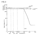
- FIG. 2 is a diagram showing the profile of the elastic modulus of the cured product of a conventional anisotropic conductive adhesive versus temperature.
- the anisotropic conductive adhesive of the present invention contains conductive particles dispersed in an epoxy-based adhesive containing an epoxy compound and a curing agent.
- EM 35 , EM 55 , EM 95 , and EM 150 are values of the elastic modulus of the cured product at 35°C, 55°C, 95°C, and 150°C, respectively
- ⁇ EM 55-95 is the rate of change in the elastic modulus between 55°C and 95°C
- ⁇ EM 95-150 is the rate of change in the elastic modulus between 95°C and 150°C
- FIG. 1 shows an example of the profile of the elastic modulus satisfying the expressions (1) to (5) (the vertical axis represents the elastic modulus, and the horizontal axis represents temperature).
- FIG. 2 shows an example of the profile of the elastic modulus of a conventional anisotropic conductive adhesive.
- the conventional anisotropic conductive adhesive in FIG. 2 contains no prescribed polymer compound. Therefore, the elastic modulus is almost unchanged even when the temperature is increased to some extent. However, the elastic modulus tends to sharply decrease to a large extent when the temperature exceeds a certain temperature higher than the glass transition temperature.
- the expression (1) represents that the elastic modulus at 35°C of the cured product of the anisotropic conductive adhesive falls within the range of 700 MPa to 3,000 MPa.
- the reason that the temperature "35°C" is employed is that the change in the elastic modulus of the cured product of an epoxy resin is generally relatively small at temperatures lower than 35°C and is negligible. This is the meaning to the reference temperature set to 35°C. If the elastic modulus at 35°C EM 35 is less than 700 MPa, a problem with the initial conduction reliability occurs. If the elastic modulus at 35°C EM 35 is larger than 3,000 MPa, a problem with the conduction reliability after a moisture absorption reflow test is more likely to occur.
- the expression (2) represents that the elastic modulus of the cured product of the anisotropic conductive adhesive decreases as the temperature increases from 35°C to 55°C, 95°C, and 150°C. If the elastic modulus does not decrease as the temperature increases, the internal stress in the adhesive (cured product) increases as the temperature increases. Therefore, a problem with a reduction in adhesion strength and a reduction in conduction reliability is more likely to occur.
- the temperature of 150°C has significance in that it corresponds not only to the temperature at which an LED device emits light but also to the temperature at which the anisotropic conductive adhesive is heated during solder reflowing.
- the reason that the elastic modulus is measured at two points of 55°C and 95°C between 35°C and 150°C is that, with attention being given to the relation between the effects of the present invention and the rate of reduction in elastic modulus, the use of the values of the elastic modulus measured at two points of 55°C and 95°C has been found to be experimentally appropriate.
- the expression (3) represents that the rate of change in elastic modulus ⁇ EM 95-150 between 95°C and 150°C is larger than the rate of change in elastic modulus ⁇ EM 55-95 between 55°C and 95°C. If these values are the same, the internal stress is not sufficiently relaxed. If this relation is reversed, the conduction reliability is less likely to be maintained.
- the expression (4) represents that the rate of change in elastic modulus ⁇ EM 55-95 between 55°C and 95°C is equal to or larger than 20%. If the change is less than 20%, the conduction reliability is less likely to be maintained.
- the expression (5) represents that the rate of change in elastic modulus ⁇ EM 95-150 between 95°C and 150°C is equal to or larger than 40%. If the change is less than 40%, the conduction reliability is less likely to be maintained.
- Preferred ranges of ⁇ EM 55-95 and ⁇ EM 95-150 are represented by the following expressions (4') and (5').
- the anisotropic conductive adhesive of the present invention includes conductive particles dispersed in an epoxy-based adhesive containing an epoxy compound and a curing agent.
- Preferred examples of the epoxy compound may include compounds and resins having at least two epoxy groups in their molecules. These may be a liquid form or a solid form. Specific examples may include well-known epoxy resins such as: glycidyl ethers obtained by reacting epichlorohydrin with a polyphenol such as bisphenol A, bisphenol F, bisphenol S, hexahydrobisphenol A, tetramethylbisphenol A, diarylbisphenol A, hydroquinone, catechol, resorcin, cresol, tetrabromobisphenol A, trihydroxybiphenyl, benzophenone, bisresorcinol, bisphenolhexafluoroacetone, tetramethylbisphenol A, tetramethylbisphenol F, tris(hydroxyphenyl)methane, bixylenol, phenol-novolac, and cresol novolac; polyglycidyl ethers obtained by reacting epichlorohydrin with an aliphatic polyalcohol such
- alicyclic epoxy compounds can be preferably used because the cured product can have light transmittance suitable for a mounted LED element and the like.
- Specific examples of the alicyclic epoxy compounds may include a hydrogenated product of glycidylbisphenol A (glycidyl hexahydrobisphenol A), 3,4-epoxycyclohexenylmethyl-3',4'-epoxycyclohexene carboxylate, and tris(2,3-epoxypropyl)isocyanurate (TEPIC).
- glycidylbisphenol A glycidyl hexahydrobisphenol A
- TEPIC tris(2,3-epoxypropyl)isocyanurate
- any known curing agent for epoxy compounds may be used as the above curing agent, and the curing agent used may be a latent curing agent.
- any of acid anhydride-based curing agents, amine-based curing agents, imidazole-based curing agents, and the like may be used.
- alicyclic acid anhydride-based curing agents may be preferably used because the cured product can have light transmittance suitable for a mounted LED element and the like.
- Specific examples of the alicyclic acid anhydride-based curing agents include methylhexahydrophthalic anhydride.
- the curing agent is used in an amount of preferably 80 to 120 parts by mass based on 100 parts by mass of the epoxy compound, and more preferably 95 to 105 parts by mass.
- the epoxy-based adhesive should contain, in addition to the epoxy compound and the curing agent, a polymer compound, for the purpose of relaxing the internal stress.
- a polymer compound having a weight average molecular weight of preferably 5,000 to 200,000, more preferably 10,000 to 100,000, is used.
- a polymer compound having a glass transition temperature of preferably 50°C or lower, more preferably -30 to 10°C is used.
- such a polymer compound may include acrylic resins, rubbers (NBR, SBR, NR, SIS, and hydrogenated products thereof), and olefin resins.
- the polymer compound has a functional group such as a glycidyl group or an amino group.
- Preferred examples of the polymer compound may include acrylic resins because they can provide good heat resistant properties.
- Specific examples of the acrylic resins may include copolymers of alkyl esters having 2 to 8 carbon atoms, preferably alkyl esters having 4 to 8 carbon atoms, of (meth)acrylic acid with glycidyl (meth)acrylate or dialkylaminoalkyl (meth)acrylate.
- Preferred examples of the alkyl esters having 2 to 8 carbon atoms of (meth)acrylic acid may include ethyl acrylate, butyl acrylate, and 2-ethylhexyl acrylate.
- Preferred examples of the glycidyl (meth)acrylate may include glycidyl methacrylate, and preferred examples of the dialkylaminoalkyl (meth)acrylate may include diethylaminoethyl acrylate.
- the acrylic resin composed of the above-described components may include an acrylic resin prepared by copolymerization of 100 parts by mass of ethyl acrylate, butyl acrylate, or 2-ethylhexyl acrylate with 10 to 100 parts by mass, preferably 10 to 40 parts by mass, of glycidyl methacrylate or diethylaminoethyl acrylate.
- an acrylic resin prepared by copolymerization of 100 parts by mass of butyl acrylate with 10 to 100 parts by mass, preferably 10 to 40 parts by mass, of glycidyl methacrylate is preferred because this acrylic resin has an advantage in that it is less likely to cause corrosion of silver wiring lines and silver electrodes.
- the amount used of such a polymer compound in the epoxy-based adhesive is preferably 10 to 50 parts by mass based on 100 parts by mass of the total amount of the epoxy compound, the curing agent, and the polymer compound, and more preferably 10 to 30 parts by mass.
- an imidazole compound used as a curing promoter may be added to the epoxy-based adhesive.
- Specific examples of the imidazole compound include 2-methyl-4-ethyl imidazole. If the amount used of the imidazole compound is too small, the amount of uncured component increases. If the amount used is too large, the excess curing promoter tends to facilitate the corrosion of an adhesion target. Therefore, the amount used of the imidazole compound is preferably 0.01 to 10 parts by mass based on 100 parts by mass of the curing agent and more preferably 0.1 to 5 parts by mass.
- Conductive particles conventionally used for anisotropic conductive adhesives can be used as the conductive particles constituting the epoxy-based adhesive.
- metal particles such as gold, nickel, and solder particles, resin particles plated with a metal, particles produced by coating any of the above particles with an insulating thin film, and the like may be appropriately used.
- the conductive particles, as in conventional conductive particles have a diameter of generally 3 to 10 ⁇ m.
- the amount used of the conductive particles is preferably 1 to 100 parts by mass based on 100 parts by mass of the epoxy-based adhesive and more preferably 10 to 50 parts by mass.
- any of various additives used for conventional anisotropic conductive adhesives may be added to the anisotropic conductive adhesive of the present invention.
- a silane coupling agent, a filler, a UV absorber, an antioxidant, and the like may be added.
- the anisotropic conductive adhesive of the present invention can be produced by uniformly dispersing the conductive particles in the epoxy-based adhesive using a common method.
- the anisotropic conductive adhesive may be processed into a desired form such as a paste form, a film form, or a highly viscous liquid form using a common method.
- the anisotropic conductive adhesive is of the thermosetting type and can be cured by heating to generally 150 to 250°C.
- the anisotropic conductive adhesive of the present invention can be preferably used to connect a chip component and various modules to a circuit board.
- a connection structure produced by flip-chip mounting a chip component such as an IC chip or an LED element on a circuit board using the anisotropic conductive adhesive of the present invention high conduction reliability can be maintained between the circuit board and the chip component even after the chip-mounted product is subjected to a reliability test involving heating of the chip-mounted product such as a reflow test that supports lead-free solder, a thermal shock test (TCT), a high-temperature high-humidity test, or a pressure cooker test (PCT).
- TCT thermal shock test
- PCT pressure cooker test
- the adhesion between the circuit board and the cured anisotropic conductive adhesive and between the chip component and the cured adhesive can be maintained in a good condition even after the reliability test. Examples
- a four-necked flask equipped with a stirrer and a condenser tube was charged with 100 g of butyl acrylate (BA), 10 g of glycidyl methacrylate (GMA), 0.2 g of azobisbutyronitrile, 300 g of ethyl acetate, and 5 g of acetone.
- the mixture was subjected to a polymerization reaction at 70°C for 8 hours under stirring. Then precipitated particles were collected by filtration, washed with ethanol, and dried to obtain acrylic resin C.
- the weight average molecular weight of the obtained acrylic resin C was 80,000, and its glass transition temperature was -70°C.
- a four-necked flask equipped with a stirrer and a condenser tube was charged with 100 g of 2-ethylhexyl acrylate (2EHA), 10 g of glycidyl methacrylate (GMA), 0.2 g of azobisbutyronitrile, 300 g of ethyl acetate, and 5 g of acetone.
- the mixture was subjected to a polymerization reaction at 70°C for 8 hours under stirring. Then precipitated particles were collected by filtration, washed with ethanol, and dried to obtain acrylic resin D.
- the weight average molecular weight of the obtained acrylic resin D was 80,000, and its glass transition temperature was -69°C.
- Anisotropic conductive adhesives were prepared by uniformly mixing components in compounding ratios shown in Table 1 using a planetary mixer.
- a glass epoxy circuit board having Cu traces flash-plated with Au was coated with one of the paste-like anisotropic conductive adhesives to a thickness (dry thickness) of 25 ⁇ m.
- a 1.5-mm square IC chip was placed on the applied adhesive and heated at 180°C for 30 seconds using a flip chip bonder to thermocompression-bond the IC chip, and a connection structure was thereby obtained.
- the adhesion strength (N/chip) of the IC chip in the connection structure was measured using a die shear tester (bond tester RTR-1100, RHESCA Co., Ltd.) immediately after the thermocompression-bonding (initial), after reflowing (260°C), and after the connection structure was left to stand at 150°C for 100 hours.
- the results obtained are shown in Table 1.
- the adhesion as measured under the conditions of the above adhesion test is practically preferably 50 N/chip.
- One of the anisotropic conductive adhesives was applied to release-treated PET to a dry thickness of 80 ⁇ m and placed in a furnace at 150°C to cure the adhesive. Then the cured product was peeled off the release-treated PET and cut into strips (specimens) of a length of 3.5 cm and a width of 0.4 cm.
- the values of the elastic modulus of the specimens at 35°C, 55°C, 95°C, and 150°C (EM 35 , EM 55 , EM 95 , and EM 150 ) were measured using a dynamic viscoelasticity measuring apparatus (DDV-01FP-W, A&D Company, Limited, tension mode, frequency: 11 Hz, rate of temperature rise: 5°C/min).
- the rates of change in the elastic modulus ( ⁇ EM 55-95 and ⁇ EM 95-150 ) were computed from the obtained results using the expressions (6) and (7). The results obtained are shown in Table 1.
- a glass epoxy circuit board having Cu traces flash-plated with Au was coated with one of the paste-like anisotropic conductive adhesives to a thickness (dry thickness) of 25 ⁇ m.
- a 6.3-mm square IC chip was placed on the applied adhesive and heated at 180°C for 30 seconds using a flip chip bonder to thermocompression-bond the IC chip.
- the conduction resistance of the connection structure immediately after thermocompression bonding was measured by the four-terminal method.
- connection structure was subjected to a level 4 moisture absorption reflow test (moisture absorption conditions: the connection structure was left to stand in an environment of 30°C and 60%RH for 96 hours; reflow conditions: 260°C (reflow peak temperature)) or a level 2 moisture absorption reflow test (moisture absorption conditions: the connection structure was left to stand in an environment of 85°C and 60%RH for 168 hours; reflow conditions: reflow peak temperature of 260°C), and then the conduction resistance was measured.
- moisture absorption conditions the connection structure was left to stand in an environment of 30°C and 60%RH for 96 hours; reflow conditions: 260°C (reflow peak temperature)
- a level 2 moisture absorption reflow test moisture absorption conditions: the connection structure was left to stand in an environment of 85°C and 60%RH for 168 hours; reflow conditions: reflow peak temperature of 260°C
- connection structure was subjected to a thermal shock test (TCT: -55°C for 0.5 hr ⁇ 125°C for 0.5 hr, 500 cycles), and the conduction resistance was again measured.
- TCT thermal shock test
- the connection structure was evaluated as "good (G)" when the conduction resistance was less than 1 ⁇ and as “not good (NG)” when the conduction resistance was 1 ⁇ or larger.
- the results obtained are shown in Table 1.
- the anisotropic conductive adhesive in Example 5 prepared using a polymer compound obtained by reacting acrylic resin C with glycidyl methacrylate could prevent corrosion of silver wiring lines and silver electrodes in anisotropic conduction connection portions more effectively than the anisotropic conductive adhesives in other Examples.
- the anisotropic conductive adhesive of the present invention yields a cured product having an elastic modulus that satisfies the expressions (1) to (5). Therefore, even after a chip-mounted product produced by mounting a chip component on a circuit board using the anisotropic conductive adhesive of the present invention is subjected to a reliability test involving heating of the chip-mounted product, such as a reflow test that supports lead-free solder, a thermal shock test (TCT), a high-temperature high-humidity test, or a pressure cooker test (PCT), high conduction reliability is maintained between the circuit board and the chip component.
- a reliability test involving heating of the chip-mounted product, such as a reflow test that supports lead-free solder, a thermal shock test (TCT), a high-temperature high-humidity test, or a pressure cooker test (PCT)
- the anisotropic conductive adhesive of the present invention is useful for connection of a circuit board to electronic components such as various chip components, modules, and flexible circuit boards.
Landscapes
- Chemical & Material Sciences (AREA)
- Organic Chemistry (AREA)
- Physics & Mathematics (AREA)
- Dispersion Chemistry (AREA)
- Spectroscopy & Molecular Physics (AREA)
- Engineering & Computer Science (AREA)
- Manufacturing & Machinery (AREA)
- Microelectronics & Electronic Packaging (AREA)
- Health & Medical Sciences (AREA)
- Chemical Kinetics & Catalysis (AREA)
- Medicinal Chemistry (AREA)
- Polymers & Plastics (AREA)
- Inorganic Chemistry (AREA)
- Adhesives Or Adhesive Processes (AREA)
- Conductive Materials (AREA)
- Non-Insulated Conductors (AREA)
Abstract




Description
- The present invention relates to an anisotropic conductive adhesive.
- In one widely used method of mounting a chip component such as a driver IC or an LED element on a circuit board, the chip component is flip-chip mounted on the circuit board using an anisotropic conductive film prepared by forming an epoxy-based adhesive containing conductive particles dispersed therein into a film shape (Patent Literature 1). In this method, electric connection between the chip component and the circuit board is established through the conductive particles in the anisotropic conductive film, and simultaneously the chip component is secured to the circuit board through the epoxy-based adhesive. Therefore, the connection process is short, and high production efficiency can be achieved.
- [Patent Literature 1] Japanese Patent No.
3342703 - However, when a chip-mounted product is produced by mounting a chip component on a circuit board using an anisotropic conductive film that uses an epoxy-based adhesive and the obtained chip-mounted product is subjected to a reliability test such as a reflow test that supports lead-free solder, a thermal shock test (TCT), a high-temperature high-humidity test, or a pressure cooker test (PCT), internal stress due to the difference in thermal expansion coefficient between the circuit board and the chip is generated. This may increase the possibility of generating problems in that the conduction resistance between the chip and the circuit will increase and that the chip component will peel off the circuit board. LED devices are recently receiving attention as energy-saving lighting devices but are no exception to these problems.
- The present invention has been made to solve the forgoing problems in the conventional technology, and it is an object of the present invention to maintain high conduction reliability between a circuit board and a chip component mounted on the circuit board using an anisotropic conductive adhesive even after the chip-mounted product is subjected to a reliability test involving heating of the chip-mounted product, such as a reflow test that supports lead-free solder, a thermal shock test (TCT), a high-temperature high-humidity test, or a pressure cooker test (PCT). It is also an object to maintain the adhesion between the cured anisotropic conductive adhesive and the circuit board and between the cured adhesive and the chip component in a good condition even after the reliability test.
- The present inventors have tried to use an anisotropic conductive adhesive that gives a cured product with a reduced elastic modulus, in order to relax internal stress generated in the circuit board, the chip component, and the cured product of the anisotropic conductive adhesive during a reliability test involving heating such as a solder reflow test. The inventors have found that simply reducing the elastic modulus is effective to relax the internal stress but causes a problem in that conduction reliability is significantly reduced. However, the inventors have unexpectedly found that an elastic modulus profile pattern of a curve obtained by plotting the elastic modulus versus temperature is closely related to the results of evaluation of the reliability of anisotropic conductive adhesives and that the relation can be represented by several relational expressions. Thus, the present invention has been completed.
- Accordingly, the present invention is an anisotropic conductive adhesive including: an epoxy-based adhesive containing an epoxy compound and a curing agent; and conductive particles dispersed in the epoxy-based adhesive, wherein the following expressions (1) to (5) are satisfied. In the expressions (1) to (5), EM35, EM55, EM95, and EM150 are values of the elastic modulus of the cured product at 35°C, 55°C, 95°C, and 150°C, respectively, ΔEM55-95 is the rate of change in the elastic modulus between 55°C and 95°C, and ΔEM95-150 is the rate of change in the elastic modulus between 95°C and 150°C. The rate of change in the elastic modulus ΔEM55-95 and the rate of change in the elastic modulus ΔEM95-150 are defined by the following expressions (6) and (7), respectively.
- In the present invention, the elastic modulus is a value measured according to JIS K7244-4. More specifically, the elastic modulus is measured using a dynamic viscoelasticity measuring apparatus (for example, DDV-01FP-W, A&D Company, Limited) in a tension mode under the conditions of a frequency of 11 Hz and a rate of temperature rise of 5°C/min.
-


-


- The present invention also provides a connection structure produced by flip-chip mounting a chip component on a circuit board using the above-described anisotropic conductive adhesive.
- The cured product of the anisotropic conductive adhesive of the present invention has an elastic modulus satisfying the expressions (1) to (5). Therefore, even after a chip-mounted product produced by mounting a chip component on a circuit board using the anisotropic conductive adhesive of the present invention is subjected to a reliability test involving heating of the chip-mounted product, such as a reflow test that supports lead-free solder, a thermal shock test (TCT), a high-temperature high-humidity test, or a pressure cooker test (PCT), high conduction reliability can be maintained between the circuit board and the chip component. In addition, the adhesion between the circuit board and the cured anisotropic conductive adhesive and between the chip component and the cured adhesive can be maintained in a good condition even after the reliability test. Brief Description of Drawings
-
FIG. 1 is a diagram showing the profile of the elastic modulus of the cured product of an anisotropic conductive adhesive of the present invention versus temperature.
FIG. 2 is a diagram showing the profile of the elastic modulus of the cured product of a conventional anisotropic conductive adhesive versus temperature. - The anisotropic conductive adhesive of the present invention contains conductive particles dispersed in an epoxy-based adhesive containing an epoxy compound and a curing agent. When EM35, EM55, EM95, and EM150 are values of the elastic modulus of the cured product at 35°C, 55°C, 95°C, and 150°C, respectively, ΔEM55-95 is the rate of change in the elastic modulus between 55°C and 95°C, and ΔEM95-150 is the rate of change in the elastic modulus between 95°C and 150°C, the foregoing expressions (1) to (5) are satisfied.
-
FIG. 1 shows an example of the profile of the elastic modulus satisfying the expressions (1) to (5) (the vertical axis represents the elastic modulus, and the horizontal axis represents temperature).FIG. 2 shows an example of the profile of the elastic modulus of a conventional anisotropic conductive adhesive. The conventional anisotropic conductive adhesive inFIG. 2 contains no prescribed polymer compound. Therefore, the elastic modulus is almost unchanged even when the temperature is increased to some extent. However, the elastic modulus tends to sharply decrease to a large extent when the temperature exceeds a certain temperature higher than the glass transition temperature. - The meanings of the above expressions (1) to (5) that define the anisotropic conductive adhesive of the present invention will next be described in detail.
- The expression (1) represents that the elastic modulus at 35°C of the cured product of the anisotropic conductive adhesive falls within the range of 700 MPa to 3,000 MPa. The reason that the temperature "35°C" is employed is that the change in the elastic modulus of the cured product of an epoxy resin is generally relatively small at temperatures lower than 35°C and is negligible. This is the meaning to the reference temperature set to 35°C. If the elastic modulus at 35°C EM35 is less than 700 MPa, a problem with the initial conduction reliability occurs. If the elastic modulus at 35°C EM35 is larger than 3,000 MPa, a problem with the conduction reliability after a moisture absorption reflow test is more likely to occur.
- The expression (2) represents that the elastic modulus of the cured product of the anisotropic conductive adhesive decreases as the temperature increases from 35°C to 55°C, 95°C, and 150°C. If the elastic modulus does not decrease as the temperature increases, the internal stress in the adhesive (cured product) increases as the temperature increases. Therefore, a problem with a reduction in adhesion strength and a reduction in conduction reliability is more likely to occur. The temperature of 150°C has significance in that it corresponds not only to the temperature at which an LED device emits light but also to the temperature at which the anisotropic conductive adhesive is heated during solder reflowing. The reason that the elastic modulus is measured at two points of 55°C and 95°C between 35°C and 150°C is that, with attention being given to the relation between the effects of the present invention and the rate of reduction in elastic modulus, the use of the values of the elastic modulus measured at two points of 55°C and 95°C has been found to be experimentally appropriate.
- The expression (3) represents that the rate of change in elastic modulus ΔEM95-150 between 95°C and 150°C is larger than the rate of change in elastic modulus ΔEM55-95 between 55°C and 95°C. If these values are the same, the internal stress is not sufficiently relaxed. If this relation is reversed, the conduction reliability is less likely to be maintained.
- The expression (4) represents that the rate of change in elastic modulus ΔEM55-95 between 55°C and 95°C is equal to or larger than 20%. If the change is less than 20%, the conduction reliability is less likely to be maintained. The expression (5) represents that the rate of change in elastic modulus ΔEM95-150 between 95°C and 150°C is equal to or larger than 40%. If the change is less than 40%, the conduction reliability is less likely to be maintained. Preferred ranges of ΔEM55-95 and ΔEM95-150 are represented by the following expressions (4') and (5').
-


- The specific components of the anisotropic conductive adhesive of the present invention that gives a cured product having an elastic modulus with the above-described characteristics will next be described. As described above, the anisotropic conductive adhesive of the present invention includes conductive particles dispersed in an epoxy-based adhesive containing an epoxy compound and a curing agent.
- Preferred examples of the epoxy compound may include compounds and resins having at least two epoxy groups in their molecules. These may be a liquid form or a solid form. Specific examples may include well-known epoxy resins such as: glycidyl ethers obtained by reacting epichlorohydrin with a polyphenol such as bisphenol A, bisphenol F, bisphenol S, hexahydrobisphenol A, tetramethylbisphenol A, diarylbisphenol A, hydroquinone, catechol, resorcin, cresol, tetrabromobisphenol A, trihydroxybiphenyl, benzophenone, bisresorcinol, bisphenolhexafluoroacetone, tetramethylbisphenol A, tetramethylbisphenol F, tris(hydroxyphenyl)methane, bixylenol, phenol-novolac, and cresol novolac; polyglycidyl ethers obtained by reacting epichlorohydrin with an aliphatic polyalcohol such as glycerin, neopentyl glycol, ethylene glycol, propylene glycol, butylene glycol, hexylene glycol, polyethylene glycol, and polypropylene glycol; glycidyl ether esters obtained by reacting epichlorohydrin with a hydroxy carboxylic acid such as p-oxybenzoic acid and β-oxynaphthoic acid; polyglycidyl esters obtained from polycarboxylic acids such as phthalic acid, methylphthalic acid, isophthalic acid, terephthalic acid, tetrahydrophthalic acid, hexahydrophthalic acid, endomethylenetetrahydrophthalic acid, endomethylenehexahydrophthalic acid, trimellitic acid, and polymerized fatty acids; glycidylaminoglycidyl ethers obtained from aminophenol and aminoalkylphenols; glycidylaminoglycidyl esters obtained from aminobenzoic acid; glycidylamines obtained from aniline, toluidine, tribromoaniline, xylylenediamine, diaminocyclohexane, bisaminomethylcyclohexane, 4,4'-diaminodiphenyl methane, 4,4'-diaminodiphenyl sulfone, and the like; and epoxidized polyolefins.
- Of these, alicyclic epoxy compounds can be preferably used because the cured product can have light transmittance suitable for a mounted LED element and the like. Specific examples of the alicyclic epoxy compounds may include a hydrogenated product of glycidylbisphenol A (glycidyl hexahydrobisphenol A), 3,4-epoxycyclohexenylmethyl-3',4'-epoxycyclohexene carboxylate, and tris(2,3-epoxypropyl)isocyanurate (TEPIC).
- Any known curing agent for epoxy compounds may be used as the above curing agent, and the curing agent used may be a latent curing agent. For example, any of acid anhydride-based curing agents, amine-based curing agents, imidazole-based curing agents, and the like may be used. Of these, alicyclic acid anhydride-based curing agents may be preferably used because the cured product can have light transmittance suitable for a mounted LED element and the like. Specific examples of the alicyclic acid anhydride-based curing agents include methylhexahydrophthalic anhydride.
- With regard to the amounts used of the epoxy compound and curing agent in the epoxy-based adhesive, if the amount used of the curing agent is too small, the amount of uncured epoxy compound becomes large. If the amount used is too large, the excess curing agent tends to facilitate the corrosion of an adhesion target. Therefore, the curing agent is used in an amount of preferably 80 to 120 parts by mass based on 100 parts by mass of the epoxy compound, and more preferably 95 to 105 parts by mass.
- In the present invention, it is preferable that the epoxy-based adhesive should contain, in addition to the epoxy compound and the curing agent, a polymer compound, for the purpose of relaxing the internal stress. The effect of relaxing the internal stress is small when the weight average molecular weight of the polymer compound is too small or too large. Therefore, a polymer compound having a weight average molecular weight of preferably 5,000 to 200,000, more preferably 10,000 to 100,000, is used. In addition, since the effect of relaxing the internal stress is small when the glass transition temperature of the polymer compound is too high, a polymer compound having a glass transition temperature of preferably 50°C or lower, more preferably -30 to 10°C, is used.
- Specific examples of such a polymer compound may include acrylic resins, rubbers (NBR, SBR, NR, SIS, and hydrogenated products thereof), and olefin resins. Preferably, the polymer compound has a functional group such as a glycidyl group or an amino group. Preferred examples of the polymer compound may include acrylic resins because they can provide good heat resistant properties. Specific examples of the acrylic resins may include copolymers of alkyl esters having 2 to 8 carbon atoms, preferably alkyl esters having 4 to 8 carbon atoms, of (meth)acrylic acid with glycidyl (meth)acrylate or dialkylaminoalkyl (meth)acrylate. Preferred examples of the alkyl esters having 2 to 8 carbon atoms of (meth)acrylic acid may include ethyl acrylate, butyl acrylate, and 2-ethylhexyl acrylate. Preferred examples of the glycidyl (meth)acrylate may include glycidyl methacrylate, and preferred examples of the dialkylaminoalkyl (meth)acrylate may include diethylaminoethyl acrylate.
- Particularly preferred examples of the acrylic resin composed of the above-described components may include an acrylic resin prepared by copolymerization of 100 parts by mass of ethyl acrylate, butyl acrylate, or 2-ethylhexyl acrylate with 10 to 100 parts by mass, preferably 10 to 40 parts by mass, of glycidyl methacrylate or diethylaminoethyl acrylate. Particularly, an acrylic resin prepared by copolymerization of 100 parts by mass of butyl acrylate with 10 to 100 parts by mass, preferably 10 to 40 parts by mass, of glycidyl methacrylate is preferred because this acrylic resin has an advantage in that it is less likely to cause corrosion of silver wiring lines and silver electrodes.
- If the amount used of such a polymer compound in the epoxy-based adhesive is too small, the effect of relaxing the internal stress becomes low. If the amount used is too large, it tends to be difficult to maintain the conduction reliability. Therefore, the amount used of the polymer compound is preferably 10 to 50 parts by mass based on 100 parts by mass of the total amount of the epoxy compound, the curing agent, and the polymer compound, and more preferably 10 to 30 parts by mass.
- If necessary, an imidazole compound used as a curing promoter may be added to the epoxy-based adhesive. Specific examples of the imidazole compound include 2-methyl-4-ethyl imidazole. If the amount used of the imidazole compound is too small, the amount of uncured component increases. If the amount used is too large, the excess curing promoter tends to facilitate the corrosion of an adhesion target. Therefore, the amount used of the imidazole compound is preferably 0.01 to 10 parts by mass based on 100 parts by mass of the curing agent and more preferably 0.1 to 5 parts by mass.
- Conductive particles conventionally used for anisotropic conductive adhesives can be used as the conductive particles constituting the epoxy-based adhesive. For example, metal particles such as gold, nickel, and solder particles, resin particles plated with a metal, particles produced by coating any of the above particles with an insulating thin film, and the like may be appropriately used. The conductive particles, as in conventional conductive particles, have a diameter of generally 3 to 10 µm. To ensure good anisotropic conduction properties and conduction reliability, the amount used of the conductive particles is preferably 1 to 100 parts by mass based on 100 parts by mass of the epoxy-based adhesive and more preferably 10 to 50 parts by mass.
- If necessary, any of various additives used for conventional anisotropic conductive adhesives may be added to the anisotropic conductive adhesive of the present invention. For example, a silane coupling agent, a filler, a UV absorber, an antioxidant, and the like may be added.
- The anisotropic conductive adhesive of the present invention can be produced by uniformly dispersing the conductive particles in the epoxy-based adhesive using a common method. The anisotropic conductive adhesive may be processed into a desired form such as a paste form, a film form, or a highly viscous liquid form using a common method. The anisotropic conductive adhesive is of the thermosetting type and can be cured by heating to generally 150 to 250°C.
- The anisotropic conductive adhesive of the present invention can be preferably used to connect a chip component and various modules to a circuit board. Particularly, in a connection structure produced by flip-chip mounting a chip component such as an IC chip or an LED element on a circuit board using the anisotropic conductive adhesive of the present invention, high conduction reliability can be maintained between the circuit board and the chip component even after the chip-mounted product is subjected to a reliability test involving heating of the chip-mounted product such as a reflow test that supports lead-free solder, a thermal shock test (TCT), a high-temperature high-humidity test, or a pressure cooker test (PCT). In addition, the adhesion between the circuit board and the cured anisotropic conductive adhesive and between the chip component and the cured adhesive can be maintained in a good condition even after the reliability test. Examples
- The present invention will next be specifically described by way of Examples.
- A four-necked flask equipped with a stirrer and a condenser tube was charged with 100 g of ethyl acrylate (EA), 10 g of glycidyl methacrylate (GMA), 0.2 g of azobisbutyronitrile, 300 g of ethyl acetate, and 5 g of acetone. The mixture was subjected to a polymerization reaction at 70°C for 8 hours under stirring. Then precipitated particles were collected by filtration, washed with ethanol, and dried to obtain acrylic resin A. The weight average molecular weight of the obtained acrylic resin A was 80,000, and its glass transition temperature was -40°C.
- A four-necked flask equipped with a stirrer and a condenser tube was charged with 100 g of ethyl acrylate (EA), 10 g of dimethylaminoethyl acrylate (DMAEA), 0.2 g of azobisbutyronitrile, 300 g of ethyl acetate, and 5 g of acetone. The mixture was subjected to a polymerization reaction at 70°C for 8 hours under stirring. Then precipitated particles were collected by filtration, washed with ethanol, and dried to obtain acrylic resin B. The weight average molecular weight of the obtained acrylic resin B was 80,000, and its glass transition temperature was 18°C.
- A four-necked flask equipped with a stirrer and a condenser tube was charged with 100 g of butyl acrylate (BA), 10 g of glycidyl methacrylate (GMA), 0.2 g of azobisbutyronitrile, 300 g of ethyl acetate, and 5 g of acetone. The mixture was subjected to a polymerization reaction at 70°C for 8 hours under stirring. Then precipitated particles were collected by filtration, washed with ethanol, and dried to obtain acrylic resin C. The weight average molecular weight of the obtained acrylic resin C was 80,000, and its glass transition temperature was -70°C.
- A four-necked flask equipped with a stirrer and a condenser tube was charged with 100 g of 2-ethylhexyl acrylate (2EHA), 10 g of glycidyl methacrylate (GMA), 0.2 g of azobisbutyronitrile, 300 g of ethyl acetate, and 5 g of acetone. The mixture was subjected to a polymerization reaction at 70°C for 8 hours under stirring. Then precipitated particles were collected by filtration, washed with ethanol, and dried to obtain acrylic resin D. The weight average molecular weight of the obtained acrylic resin D was 80,000, and its glass transition temperature was -69°C.
- Anisotropic conductive adhesives were prepared by uniformly mixing components in compounding ratios shown in Table 1 using a planetary mixer.
- The adhesion, elastic modulus, and conduction reliability of each of the paste-like anisotropic conductive adhesives obtained in Examples 1 to 6 and Comparative Examples 1 to 5 were measured as described below.
- A glass epoxy circuit board having Cu traces flash-plated with Au was coated with one of the paste-like anisotropic conductive adhesives to a thickness (dry thickness) of 25 µm. A 1.5-mm square IC chip was placed on the applied adhesive and heated at 180°C for 30 seconds using a flip chip bonder to thermocompression-bond the IC chip, and a connection structure was thereby obtained. The adhesion strength (N/chip) of the IC chip in the connection structure was measured using a die shear tester (bond tester RTR-1100, RHESCA Co., Ltd.) immediately after the thermocompression-bonding (initial), after reflowing (260°C), and after the connection structure was left to stand at 150°C for 100 hours. The results obtained are shown in Table 1. The adhesion as measured under the conditions of the above adhesion test is practically preferably 50 N/chip.
- One of the anisotropic conductive adhesives was applied to release-treated PET to a dry thickness of 80 µm and placed in a furnace at 150°C to cure the adhesive. Then the cured product was peeled off the release-treated PET and cut into strips (specimens) of a length of 3.5 cm and a width of 0.4 cm. The values of the elastic modulus of the specimens at 35°C, 55°C, 95°C, and 150°C (EM35, EM55, EM95, and EM150) were measured using a dynamic viscoelasticity measuring apparatus (DDV-01FP-W, A&D Company, Limited, tension mode, frequency: 11 Hz, rate of temperature rise: 5°C/min). The rates of change in the elastic modulus (ΔEM55-95 and ΔEM95-150) were computed from the obtained results using the expressions (6) and (7). The results obtained are shown in Table 1.
- A glass epoxy circuit board having Cu traces flash-plated with Au was coated with one of the paste-like anisotropic conductive adhesives to a thickness (dry thickness) of 25 µm. A 6.3-mm square IC chip was placed on the applied adhesive and heated at 180°C for 30 seconds using a flip chip bonder to thermocompression-bond the IC chip. The conduction resistance of the connection structure immediately after thermocompression bonding was measured by the four-terminal method. Then the connection structure was subjected to a level 4 moisture absorption reflow test (moisture absorption conditions: the connection structure was left to stand in an environment of 30°C and 60%RH for 96 hours; reflow conditions: 260°C (reflow peak temperature)) or a level 2 moisture absorption reflow test (moisture absorption conditions: the connection structure was left to stand in an environment of 85°C and 60%RH for 168 hours; reflow conditions: reflow peak temperature of 260°C), and then the conduction resistance was measured. After the measurement, the connection structure was subjected to a thermal shock test (TCT: -55°C for 0.5 hr ←→ 125°C for 0.5 hr, 500 cycles), and the conduction resistance was again measured. The connection structure was evaluated as "good (G)" when the conduction resistance was less than 1Ω and as "not good (NG)" when the conduction resistance was 1Ω or larger. The results obtained are shown in Table 1.
-
[Table 1] Example Comparative Example Component Name (Parts By Mass) 1 2 3 4 5 6 1 2 3 4 5 Alicyclic Epoxy Compound *1 50 39 28 50 39 39 50 22 90 50 42 Acrylic Resin A *2 10 30 50 - - - - 60 - - 2 Acrylic Resin B *3 - - - 30 - - - - - - - Acrylic Resin C *4 - - - - 30 - - - - - - Acrylic Resin D *5 - - - - - 30 - - - - - Phenoxy Resin *6 - - - - - - 10 - 10 10 - Curing Agent *7 40 31 22 40 31 31 40 18 - 40 56 Curing Promoter *8 1 1 1 1 1 1 - 1 10 1 1 Conductive Particles *9 30 30 30 30 30 30 30 30 30 30 30 Adhesion (N/Chip) Initial 98.0 107.8 127.4 98.0 90.0 85.0 39.2 127.4 49.0 49.0 49.0 After Reflowing 98.0 107.4 117.6 98.0 90.0 85.0 19.6 107.4 39.2 39.2 39.2 150°C 100h 78.4 88.2 98.0 88.2 75.0 65.0 9.8 39.2 19.6 19.6 29.4 Elastic Modulus (Mpa) EM35 2600 1400 900 1600 2000 2100 3200 600 1900 1700 2100 EM55 2200 1100 700 1200 1800 1800 2900 400 1700 1700 1900 EM95 1500 830 500 800 1200 1500 2600 300 1500 1600 1500 EM150 800 270 200 400 380 680 2500 100 46 1300 1000 Rate of Change in Elastic Modulus (%) ΔEM55-95 32 25 29 33 33 25 10 25 12 6 21 ΔEM95-150 47 67 60 50 67 55 4 67 97 19 33 Conduction Reliability Initial G G G G G G G NG G G G After Level 4 Moisture Reflowing G G G G G G G - G G G After Level 2 Moisture Absorption Reflowing G G G G G G NG - NG NG NG After 500 TCT Cycles G G G G G G - - - - - *1 GLYCIDYL HEXAHYDROBISPHENOLA (YX8000, JER CO., LTD.)
*2 REFERENCE EXAMPLE 1
*3 REFERENCE EXAMPLE 2
*4 REFERENCE EXAMPLE 3
*5 REFERENCE EXAMPLE 4
*6 WEIGHT AVERAGE MOLECULAR WEIGHT: 3700, GLASS TRANSITION TEMPERATURE: 70°C (YP70, TOHTO KASEI CO., LTD.)
*7 METHYLHEXAHYDROPHTHALIC ANHYDRIDE
*8 2-ETHYL-4-METHYLIMIDAZOLE(SHIKOKU CHEMICALS CORPORATION)
*9 Particles prepared by plating surface of cross-linked polystyrene particles of 5 µm diameter with Ni/Au - As can be seen from the results in Table 1, in the anisotropic conductive adhesives in Examples 1 to 6 having an elastic modulus satisfying the expressions (1) to (5) below, their initial adhesion, adhesion after reflowing, and adhesion after 100 hours at 150°C were good. As also can be seen from the results, the initial conduction reliability, conduction reliability after the level 4 moisture absorption reflowing, conduction reliability after the level 2 moisture absorption reflowing, and conduction reliability after 500 thermal shock cycles were good. The anisotropic conductive adhesive in Example 5 prepared using a polymer compound obtained by reacting acrylic resin C with glycidyl methacrylate could prevent corrosion of silver wiring lines and silver electrodes in anisotropic conduction connection portions more effectively than the anisotropic conductive adhesives in other Examples.
-


- However, in Comparative Example 1, since EM35 is higher than 3,000 MPa, the expression (1) is not satisfied, and also the expressions (3) to (5) are not satisfied. Therefore, not only the desired adhesion, but also the desired conduction reliability were not achieved after the moisture absorption reflow test performed under severer conditions.
- In Comparative Example 2, since EM35 is less than 700 MPa, the expression (1) is not satisfied. Therefore, the desired adhesion characteristics were not obtained after the connection structure was left to stand at 150°C for 100 hours. In addition, the desired conduction reliability was not obtained even immediately after the production of the connection structure.
- In Comparative Example 3, since the rate of change in elastic modulus ΔEM55-95 is less than 20%, the expression (4) is not satisfied. Therefore, the desired adhesion characteristics were not obtained after reflowing and after the connection structure was left to stand at 150°C for 100 hours. The desired conduction reliability was not achieved after the moisture absorption reflow test performed under severer conditions.
- In Comparative Example 4, since the rate of change in elastic modulus ΔEM55-95 is less than 20% and also ΔEM95- 150 is less than 40%, the expressions (4) and (5) are not satisfied. Therefore, the desired adhesion characteristics were not obtained after reflowing and after the connection structure was left to stand at 150°C for 100 hours. The desired conduction reliability was not achieved after the moisture absorption reflow test performed under severer conditions.
- In Comparative Example 5, since the rate of change in elastic modulus ΔEM95-150 is less than 40, the expression (5) is not satisfied. Therefore, the desired adhesion characteristics were not obtained after reflowing and after the connection structure was left to stand at 150°C for 100 hours. The desired conduction reliability was not achieved after the moisture absorption reflow test performed under severer conditions.
- The anisotropic conductive adhesive of the present invention yields a cured product having an elastic modulus that satisfies the expressions (1) to (5). Therefore, even after a chip-mounted product produced by mounting a chip component on a circuit board using the anisotropic conductive adhesive of the present invention is subjected to a reliability test involving heating of the chip-mounted product, such as a reflow test that supports lead-free solder, a thermal shock test (TCT), a high-temperature high-humidity test, or a pressure cooker test (PCT), high conduction reliability is maintained between the circuit board and the chip component. In addition, the adhesion between the circuit board and the cured anisotropic conductive adhesive and between the chip component and the cured adhesive can be maintained in a good condition even after the reliability test. Therefore, the anisotropic conductive adhesive of the present invention is useful for connection of a circuit board to electronic components such as various chip components, modules, and flexible circuit boards.
Claims (14)
- An anisotropic conductive adhesive comprising: an epoxy-based adhesive containing an epoxy compound and a curing agent; and conductive particles dispersed in the epoxy-based adhesive, wherein the following expressions (1) to (5) are satisfied, in which EM35, EM55, EM95, and EM150 are values of an elastic modulus of a cured product of the adhesive at 35°C, 55°C, 95°C°C, and 150°C, respectively, ΔEM55-95 is a rate of change in the elastic modulus between 55°C and 95°C, and ΔEM95-150 is a rate of change in the elastic modulus between 95°C and 150°C,



- The anisotropic conductive adhesive according to claim 1, wherein the rates of change in the elastic modulus ΔEM55-95 and ΔEM95-150 satisfy the respective expressions (4') and (5'),


- The anisotropic conductive adhesive according to claim 1 or 2, wherein the epoxy-based adhesive contains the curing agent in an amount of 80 to 120 parts by mass based on 100 parts by mass of the epoxy compound.
- The anisotropic conductive adhesive according to any of claims 1 to 3, wherein the epoxy-based adhesive contains, in addition to the epoxy compound, a polymer compound having a weight average molecular weight of 5,000 to 200,000 and a glass transition temperature of 50°C or lower.
- The anisotropic conductive adhesive according to claim 4, wherein the polymer compound is a copolymer of an alkyl ester having 2 to 8 carbon atoms of (meth)acrylic acid with glycidyl (meth)acrylate or dialkylaminoalkyl (meth)acrylate.
- The anisotropic conductive adhesive according to claim 4, wherein the polymer compound is an acrylic resin prepared by copolymerization of 100 parts by mass of ethyl acrylate, butyl acrylate, or 2-ethylhexyl acrylate with 10 to 100 parts by mass of glycidyl methacrylate or diethylaminoethyl acrylate.
- The anisotropic conductive adhesive according to claim 4, wherein the polymer compound is an acrylic resin prepared by copolymerization of 100 parts by mass of butyl acrylate with 10 to 100 parts by mass of glycidyl methacrylate.
- The anisotropic conductive adhesive according to any of claims 4 to 7, wherein an amount used of the polymer compound in the epoxy-based adhesive is 10 to 50 parts by mass based on 100 parts by mass of a total amount of the epoxy compound, the curing agent, and the polymer compound.
- The anisotropic conductive adhesive according to any of claims 1 to 8, wherein the epoxy compound is an alicyclic epoxy compound and the curing agent is an alicyclic acid anhydride-based curing agent.
- The anisotropic conductive adhesive according to claim 9, wherein the alicyclic epoxy compound is a hydrogenated product of glycidylbisphenol A or 3,4-epoxycyclohexenylmethyl-3',4'-epoxycyclohexene carboxylate, and the alicyclic acid anhydride-based curing agent is methylhexahydrophthalic anhydride.
- The anisotropic conductive adhesive according to any of claims 1 to 10, further comprising 2-methyl-4-ethyl imidazole as a curing promoter in an amount of 0.01 to 10 parts by mass based on 100 parts by mass of the curing agent.
- The anisotropic conductive adhesive according to any of claims 1 to 11, wherein an amount used of the conductive particles is 1 to 100 parts by mass based on 100 parts by mass of the epoxy-based adhesive.
- A connection structure produced by flip-chip mounting a chip component on a circuit board using the anisotropic conductive adhesive according to any of claims 1 to 12.
- The connection structure according to claim 13, wherein the chip component is an LED element.
Applications Claiming Priority (1)
| Application Number | Priority Date | Filing Date | Title |
|---|---|---|---|
| PCT/JP2010/050370 WO2011086680A1 (en) | 2010-01-15 | 2010-01-15 | Anisotropic electrically-conductive adhesive agent |
Publications (2)
| Publication Number | Publication Date |
|---|---|
| EP2524953A1 true EP2524953A1 (en) | 2012-11-21 |
| EP2524953A4 EP2524953A4 (en) | 2015-08-12 |
Family
ID=44303984
Family Applications (1)
| Application Number | Title | Priority Date | Filing Date |
|---|---|---|---|
| EP10843039.8A Withdrawn EP2524953A4 (en) | 2010-01-15 | 2010-01-15 | Anisotropic electrically-conductive adhesive agent |
Country Status (7)
| Country | Link |
|---|---|
| US (1) | US8790547B2 (en) |
| EP (1) | EP2524953A4 (en) |
| JP (1) | JPWO2011086680A1 (en) |
| KR (1) | KR101553436B1 (en) |
| CN (1) | CN102695768B (en) |
| TW (1) | TWI476267B (en) |
| WO (1) | WO2011086680A1 (en) |
Families Citing this family (4)
| Publication number | Priority date | Publication date | Assignee | Title |
|---|---|---|---|---|
| JP5986679B2 (en) * | 2013-03-29 | 2016-09-06 | トッパン・フォームズ株式会社 | Laminated body |
| KR101629100B1 (en) * | 2014-11-26 | 2016-06-09 | 롯데케미칼 주식회사 | Bumper system for vehicles |
| KR20170116624A (en) * | 2016-04-11 | 2017-10-20 | 주식회사 잉크테크 | Conductive Paste Composition and method for Bonding Structures Using the same |
| CN108956438B (en) * | 2018-07-23 | 2020-12-15 | 长安大学 | Ultraviolet radiation-oxygen-temperature-humidity coupled asphalt aging test device and method |
Family Cites Families (20)
| Publication number | Priority date | Publication date | Assignee | Title |
|---|---|---|---|---|
| JPH0520918A (en) * | 1991-07-14 | 1993-01-29 | Sony Chem Corp | Conductive paste |
| TW505686B (en) * | 1996-07-15 | 2002-10-11 | Hitachi Chemical Ltd | Film-like adhesive for connecting circuit and circuit board |
| JPH10259227A (en) * | 1997-03-19 | 1998-09-29 | Dainippon Ink & Chem Inc | New epoxy resin and epoxy resin composition |
| JPH11335641A (en) * | 1998-05-26 | 1999-12-07 | Sekisui Chem Co Ltd | Anisotropic conductive photo-curing paste and bonding method using the same |
| AU8648598A (en) * | 1998-08-13 | 2000-03-06 | Hitachi Chemical Company, Ltd. | Adhesive for bonding circuit members, circuit board, and method of producing thesame |
| WO2000060614A1 (en) * | 1999-04-01 | 2000-10-12 | Mitsui Chemicals, Inc. | Anisotropically conductive paste |
| JP3904798B2 (en) * | 1999-04-01 | 2007-04-11 | 三井化学株式会社 | Anisotropic conductive paste |
| EP1586615B1 (en) * | 1999-06-18 | 2007-08-15 | Hitachi Chemical Company, Ltd. | Adhesive, adhesive member, interconnecting substrate for semiconductor mounting having adhesive member, and semiconductor device containing the same |
| JP2001115127A (en) * | 1999-10-19 | 2001-04-24 | Hitachi Chem Co Ltd | Electrically conductive adhesive and wiring board using the same |
| JP3491595B2 (en) * | 2000-02-25 | 2004-01-26 | ソニーケミカル株式会社 | Anisotropic conductive adhesive film |
| JP2002201450A (en) | 2000-12-28 | 2002-07-19 | Hitachi Chem Co Ltd | Adhesive composition, circuit terminal connection method using the same, and circuit terminal connection structure |
| JP2003147306A (en) | 2001-11-09 | 2003-05-21 | Fujitsu Ltd | Conductive adhesive |
| JP2004039983A (en) * | 2002-07-05 | 2004-02-05 | Rohm Co Ltd | Semiconductor light emitting device |
| JP2005050773A (en) * | 2003-07-31 | 2005-02-24 | Asahi Glass Co Ltd | Organic LED element |
| DE10342615A1 (en) | 2003-09-12 | 2005-05-19 | Basf Ag | Epoxy adhesive with increased elasticity |
| JP4576966B2 (en) | 2004-09-29 | 2010-11-10 | 東亞合成株式会社 | Adhesive composition containing epoxy resin |
| JP2006104273A (en) | 2004-10-04 | 2006-04-20 | Toppan Printing Co Ltd | Conductive adhesive, conductive film, and printed wiring board using the same |
| JP2007112949A (en) | 2005-10-24 | 2007-05-10 | Sumitomo Electric Ind Ltd | Anisotropic conductive adhesive |
| JP5499448B2 (en) * | 2008-07-16 | 2014-05-21 | デクセリアルズ株式会社 | Anisotropic conductive adhesive |
| JP2011100927A (en) | 2009-11-09 | 2011-05-19 | Sony Chemical & Information Device Corp | Bonding agent composition |
-
2010
- 2010-01-15 WO PCT/JP2010/050370 patent/WO2011086680A1/en not_active Ceased
- 2010-01-15 CN CN201080061381.4A patent/CN102695768B/en not_active Expired - Fee Related
- 2010-01-15 KR KR1020127018322A patent/KR101553436B1/en not_active Expired - Fee Related
- 2010-01-15 EP EP10843039.8A patent/EP2524953A4/en not_active Withdrawn
- 2010-01-15 US US13/517,492 patent/US8790547B2/en not_active Expired - Fee Related
- 2010-01-15 JP JP2011549816A patent/JPWO2011086680A1/en active Pending
- 2010-08-23 TW TW099128067A patent/TWI476267B/en not_active IP Right Cessation
Non-Patent Citations (1)
| Title |
|---|
| See references of WO2011086680A1 * |
Also Published As
| Publication number | Publication date |
|---|---|
| CN102695768A (en) | 2012-09-26 |
| KR20120123329A (en) | 2012-11-08 |
| EP2524953A4 (en) | 2015-08-12 |
| TW201124504A (en) | 2011-07-16 |
| CN102695768B (en) | 2015-04-29 |
| JPWO2011086680A1 (en) | 2013-05-16 |
| HK1172638A1 (en) | 2013-04-26 |
| TWI476267B (en) | 2015-03-11 |
| KR101553436B1 (en) | 2015-09-15 |
| WO2011086680A1 (en) | 2011-07-21 |
| US20120262931A1 (en) | 2012-10-18 |
| US8790547B2 (en) | 2014-07-29 |
Similar Documents
| Publication | Publication Date | Title |
|---|---|---|
| US8636924B2 (en) | Anisotropic conductive adhesive | |
| JP5619466B2 (en) | Curable resin composition, adhesive epoxy resin paste, die bond agent, non-conductive paste, adhesive epoxy resin film, non-conductive epoxy resin film, anisotropic conductive paste and anisotropic conductive film | |
| US20120168814A1 (en) | Adhesive composition | |
| US8790547B2 (en) | Anisotropic conductive adhesive | |
| JP5556488B2 (en) | Adhesive for connecting counter electrode | |
| JP5742991B2 (en) | Anisotropic conductive adhesive | |
| JP6048524B2 (en) | Adhesive composition | |
| JP5983694B2 (en) | Anisotropic conductive adhesive | |
| TWI814761B (en) | adhesive film | |
| HK1172638B (en) | Anisotropic electrically-conductive adhestive agent | |
| HK1155194B (en) | Anisotropic conductive adhesive | |
| HK1191665A (en) | Anisotropic conductive adhesive | |
| JP4826359B2 (en) | Liquid resin composition and semiconductor device produced using liquid resin composition |
Legal Events
| Date | Code | Title | Description |
|---|---|---|---|
| PUAI | Public reference made under article 153(3) epc to a published international application that has entered the european phase |
Free format text: ORIGINAL CODE: 0009012 |
|
| 17P | Request for examination filed |
Effective date: 20120712 |
|
| AK | Designated contracting states |
Kind code of ref document: A1 Designated state(s): AT BE BG CH CY CZ DE DK EE ES FI FR GB GR HR HU IE IS IT LI LT LU LV MC MK MT NL NO PL PT RO SE SI SK SM TR |
|
| DAX | Request for extension of the european patent (deleted) | ||
| RAP1 | Party data changed (applicant data changed or rights of an application transferred) |
Owner name: DEXERIALS CORPORATION |
|
| RA4 | Supplementary search report drawn up and despatched (corrected) |
Effective date: 20150714 |
|
| RIC1 | Information provided on ipc code assigned before grant |
Ipc: H01R 11/01 20060101ALI20150708BHEP Ipc: C09J 163/00 20060101AFI20150708BHEP Ipc: H05K 1/09 20060101ALI20150708BHEP Ipc: C09J 11/06 20060101ALI20150708BHEP Ipc: C09J 11/04 20060101ALI20150708BHEP Ipc: H01B 1/22 20060101ALI20150708BHEP Ipc: H05K 3/22 20060101ALI20150708BHEP Ipc: C09J 9/02 20060101ALI20150708BHEP |
|
| STAA | Information on the status of an ep patent application or granted ep patent |
Free format text: STATUS: THE APPLICATION IS DEEMED TO BE WITHDRAWN |
|
| 18D | Application deemed to be withdrawn |
Effective date: 20160211 |