EP2524835A1 - Electrically driven vehicle - Google Patents
Electrically driven vehicle Download PDFInfo
- Publication number
- EP2524835A1 EP2524835A1 EP10843040A EP10843040A EP2524835A1 EP 2524835 A1 EP2524835 A1 EP 2524835A1 EP 10843040 A EP10843040 A EP 10843040A EP 10843040 A EP10843040 A EP 10843040A EP 2524835 A1 EP2524835 A1 EP 2524835A1
- Authority
- EP
- European Patent Office
- Prior art keywords
- battery
- generator unit
- amount
- charge
- vehicle
- Prior art date
- Legal status (The legal status is an assumption and is not a legal conclusion. Google has not performed a legal analysis and makes no representation as to the accuracy of the status listed.)
- Granted
Links
Images


Classifications
-
- B—PERFORMING OPERATIONS; TRANSPORTING
- B60—VEHICLES IN GENERAL
- B60L—PROPULSION OF ELECTRICALLY-PROPELLED VEHICLES; SUPPLYING ELECTRIC POWER FOR AUXILIARY EQUIPMENT OF ELECTRICALLY-PROPELLED VEHICLES; ELECTRODYNAMIC BRAKE SYSTEMS FOR VEHICLES IN GENERAL; MAGNETIC SUSPENSION OR LEVITATION FOR VEHICLES; MONITORING OPERATING VARIABLES OF ELECTRICALLY-PROPELLED VEHICLES; ELECTRIC SAFETY DEVICES FOR ELECTRICALLY-PROPELLED VEHICLES
- B60L58/00—Methods or circuit arrangements for monitoring or controlling batteries or fuel cells, specially adapted for electric vehicles
- B60L58/10—Methods or circuit arrangements for monitoring or controlling batteries or fuel cells, specially adapted for electric vehicles for monitoring or controlling batteries
- B60L58/12—Methods or circuit arrangements for monitoring or controlling batteries or fuel cells, specially adapted for electric vehicles for monitoring or controlling batteries responding to state of charge [SoC]
-
- B—PERFORMING OPERATIONS; TRANSPORTING
- B60—VEHICLES IN GENERAL
- B60L—PROPULSION OF ELECTRICALLY-PROPELLED VEHICLES; SUPPLYING ELECTRIC POWER FOR AUXILIARY EQUIPMENT OF ELECTRICALLY-PROPELLED VEHICLES; ELECTRODYNAMIC BRAKE SYSTEMS FOR VEHICLES IN GENERAL; MAGNETIC SUSPENSION OR LEVITATION FOR VEHICLES; MONITORING OPERATING VARIABLES OF ELECTRICALLY-PROPELLED VEHICLES; ELECTRIC SAFETY DEVICES FOR ELECTRICALLY-PROPELLED VEHICLES
- B60L50/00—Electric propulsion with power supplied within the vehicle
- B60L50/50—Electric propulsion with power supplied within the vehicle using propulsion power supplied by batteries or fuel cells
- B60L50/60—Electric propulsion with power supplied within the vehicle using propulsion power supplied by batteries or fuel cells using power supplied by batteries
- B60L50/61—Electric propulsion with power supplied within the vehicle using propulsion power supplied by batteries or fuel cells using power supplied by batteries by batteries charged by engine-driven generators, e.g. series hybrid electric vehicles
- B60L50/62—Electric propulsion with power supplied within the vehicle using propulsion power supplied by batteries or fuel cells using power supplied by batteries by batteries charged by engine-driven generators, e.g. series hybrid electric vehicles charged by low-power generators primarily intended to support the batteries, e.g. range extenders
-
- Y—GENERAL TAGGING OF NEW TECHNOLOGICAL DEVELOPMENTS; GENERAL TAGGING OF CROSS-SECTIONAL TECHNOLOGIES SPANNING OVER SEVERAL SECTIONS OF THE IPC; TECHNICAL SUBJECTS COVERED BY FORMER USPC CROSS-REFERENCE ART COLLECTIONS [XRACs] AND DIGESTS
- Y02—TECHNOLOGIES OR APPLICATIONS FOR MITIGATION OR ADAPTATION AGAINST CLIMATE CHANGE
- Y02T—CLIMATE CHANGE MITIGATION TECHNOLOGIES RELATED TO TRANSPORTATION
- Y02T10/00—Road transport of goods or passengers
- Y02T10/60—Other road transportation technologies with climate change mitigation effect
- Y02T10/62—Hybrid vehicles
-
- Y—GENERAL TAGGING OF NEW TECHNOLOGICAL DEVELOPMENTS; GENERAL TAGGING OF CROSS-SECTIONAL TECHNOLOGIES SPANNING OVER SEVERAL SECTIONS OF THE IPC; TECHNICAL SUBJECTS COVERED BY FORMER USPC CROSS-REFERENCE ART COLLECTIONS [XRACs] AND DIGESTS
- Y02—TECHNOLOGIES OR APPLICATIONS FOR MITIGATION OR ADAPTATION AGAINST CLIMATE CHANGE
- Y02T—CLIMATE CHANGE MITIGATION TECHNOLOGIES RELATED TO TRANSPORTATION
- Y02T10/00—Road transport of goods or passengers
- Y02T10/60—Other road transportation technologies with climate change mitigation effect
- Y02T10/70—Energy storage systems for electromobility, e.g. batteries
-
- Y—GENERAL TAGGING OF NEW TECHNOLOGICAL DEVELOPMENTS; GENERAL TAGGING OF CROSS-SECTIONAL TECHNOLOGIES SPANNING OVER SEVERAL SECTIONS OF THE IPC; TECHNICAL SUBJECTS COVERED BY FORMER USPC CROSS-REFERENCE ART COLLECTIONS [XRACs] AND DIGESTS
- Y02—TECHNOLOGIES OR APPLICATIONS FOR MITIGATION OR ADAPTATION AGAINST CLIMATE CHANGE
- Y02T—CLIMATE CHANGE MITIGATION TECHNOLOGIES RELATED TO TRANSPORTATION
- Y02T10/00—Road transport of goods or passengers
- Y02T10/60—Other road transportation technologies with climate change mitigation effect
- Y02T10/7072—Electromobility specific charging systems or methods for batteries, ultracapacitors, supercapacitors or double-layer capacitors
Definitions
- the present invention relates to electrically driven vehicles, and more particularly, to an electrically driven vehicle in which a generator unit that charges a battery usable for running is detachably mounted.
- Patent Document 1 discloses an electric vehicle in which a first battery is mounted and a generator unit or a second battery is detachably mounted.
- the electric vehicle disclosed in Patent Document 1 is configured to mount the second battery when the electric vehicle is driven around a charge station or home, and to mount the generator unit when the electric vehicle is driven a long ways.
- Patent Document 2 discloses an art that is considered as being relative to the present invention regarding mounting of a generator capable of charging a battery mounted in a vehicle.
- Patent Documents 3 through 5 disclose arts that are considered as being relative to the present invention in terms of mounting of more than one battery.
- the amount of charge of the battery may be managed to output an alarm for urging the user to charge the battery when the amount of charge of the battery reduces.
- a generator unit is detachably mounted in the electrically driven vehicle
- the case where the generator unit has been mounted does not always need to secure a certain amount of charge of the battery that is estimated to be feasible for retreat running or running up to a charge station.
- the operation start timing of the generator unit may affect the appropriate use of the battery. That is, if the operation of the generator unit is started relatively early with respect to the remaining amount of charge of the battery, the battery will not be efficiently utilized accordingly. In contrast, if the operation of the generator unit is started relatively late, the battery will be worked hard accordingly.
- the electric vehicle disclosed in Patent Document 1 configured to detachably mount the generator unit does not have a specific consideration about the management of the amount of charge of the first battery between the case where the generator unit has been mounted and the case where the generator unit has not been mounted. Therefore, the electric vehicle disclosed in Patent Document 1 has a problem because the first battery may not be always utilized appropriately.
- the present invention was made in view of the above problem and aims to provide an electrically driven vehicle capable of ensuring proper use of a battery when a generator unit is detachably mounted.
- the present invention for solving the above problem is an electrically driven vehicle comprising: a vehicle body; a first battery mounted in the vehicle body and usable for running; a generator unit that is detachably mounted in the vehicle body and charges the first battery; diagnosis means for diagnosing whether the generator unit is capable of generating power; and management means for managing an amount of charge of the first battery according to a diagnostic result of the diagnosis means.
- the present invention is preferably configured so that a lower usage limit is provided for the amount of charge of the first battery; and when the diagnosis means determines that the generator unit is capable of generating power, the management means changes, as a management of the amount of charge of the first battery, the lower usage limit to a level lower than that used when the generator unit is not capable of generating power.
- the present invention is preferably configured so that a second battery usable for running is detachably mounted in the vehicle body; and the diagnosis means diagnoses whether the second battery is usable, and when the diagnosis means determines that the generator unit is capable of generating power, the management means changes, as the management of the amount of charge of the first battery, the lower usage limit to a level lower than that used when the second battery is not usable.
- the present invention is preferably configured so that a lower usage limit is provided for the amount of charge of the first battery; and when the diagnosis means determines that the generator unit is capable of generating power, the management means changes, as a management of the amount of charge of the first battery, the lower usage limit to a level higher than that used when the generator unit is not capable of generating power.
- the present invention is preferably configured so that a second battery usable for running is detachably mounted in the vehicle body; and the diagnosis means diagnoses whether the second battery is usable, and when the diagnosis means determines that the generator unit is capable of generating power, the management means changes, as the management of the amount of charge of the first battery, the lower usage limit to a level higher than that used when the second battery is not usable.
- the present invention is preferably configured so that the diagnosis means diagnoses a generating feasible power amount of the generator unit in a process of diagnosing whether the generator unit is capable of generating power; and the management means further amend the management of the amount of charge of the first battery according to the generating feasible power amount.
- an electrically driven vehicle 1A has a vehicle body 10 in which a generator unit 11, a battery 12, and an electric motor 13 are mounted.
- the electrically driven vehicle 1A is configured so that the generator unit 11 is detachably mounted.
- the electrically driven vehicle 1A capable of detachably installing the generator unit 11 can be operated in a state in which the generator unit 11 is not mounted and is electrically disconnected.
- the generator unit 11 is an engine driven type of generator unit, and is equipped, as illustrated in FIG. 2 , with an engine 111, a generator 112,a generator-unit-side ECU 113, and a generator-unit-side fuel tank 114.
- the engine 111 drives the generator 112, which generates alternating current. Then, the alternating current thus generated is converted to direct current by a not-illustrated rectifying circuit before being charged in the battery 12.
- the generator-unit-side ECU 113 is provided for primarily controlling the engine 111.
- the battery 12 is a direct current battery, and is electrically and detachably connected to the generator unit 11 via high-voltage system wires that are power-system wires. Energy generated by the generator unit 11 is stored in the battery 12 via the high-voltage system wires.
- the battery 12 may be configured to have multiple batteries having a rated DC voltage of 12 V connected in series, for example.
- the electric motor 13 is a source for running, and is a DC motor. The electric motor 13 is supplied with energy from the battery 12, and rotates an output shaft 14. Then, the rotary output is transmitted, via a transmission 15, to a pair of right and left rear wheels 2, which are driving wheels, so that the rear wheels 2 can be driven.
- the electrically driven vehicle 1A is a series hybrid type of electrically driven vehicle.
- the electrically driven vehicle 1A is equipped, in addition to the pair of right and left rear wheels 2 of the driving wheels, with a pair of right and left front wheels 3 that are steering wheels, a handle 4 for manually steering the front wheels 3, an acceleration pedal 5 for changing the number of revolutions of the electric motor 13, a brake pedal 6 and a brake unit 7 for braking the vehicle, and drum brakes 8 coupled with the brake pedal 6 by wires, joined to the brake unit 7 and provided to the front wheels 3 and the rear wheels 2.
- the acceleration pedal 5 is provided with an acceleration position sensor 26 that senses the amount of depression of the acceleration pedal 5, and the brake pedal 6 is provided with a brake switch 62 that senses whether the brake pedal 6 is depressed or not.
- the electrically driven vehicle 1A is further provided with a key switch 21, and a generation switch 22.
- the key switch 21 and the generation switch 22 are switches that enable selective switching operation between ON and OFF.
- the key switch 21 is operation means for making an operation request to the electric motor 13. Specifically, when the key switch 21 is ON, the operation request to the electric motor 13 is made. When the key switch 21 is OFF, the operation request to the electric motor 13 is not made.
- the generation switch 22 is operation means for making a request to the generator unit 11. Specifically, when the generation switch 22 is ON, the operation request to the generator unit 11 is made. When the generation switch 22 is OFF, the operation request to the generator unit 11 is not made.
- the key switch 21 and the generation switch 22 are provided on a not-illustrated instrument panel.
- the electrically driven vehicle 1A is equipped with a vehicle-side ECU 50A, which is a first control unit.
- the vehicle-side ECU 50A is equipped with a microcomputer composed of a CPU, a ROM, a RAM and so on, and an input/output circuit, which are not illustrated.
- the generator-unit-side ECU 113 which is a second control unit, is configured similarly.
- the generator unit 11 (more specifically, the generator-unit-side ECU 113) is electrically and detachably connected to the vehicle-side ECU 50A.
- the vehicle-side ECU 50A and the generator unit 11 are connected together via low-voltage system wires, which are control-system wires.
- Various objects to be controlled such as the electric motor 13 are electrically connected to the vehicle-side ECU 50A, and further, various sensors and switches such as the key switch 21, the acceleration position sensor 61, the brake switch 62, and a first mount sensor 63 that is a state sensing means capable of detecting whether the generator unit 11 is mounted or not are electrically connected thereto.
- a first battery 12 is electrically connected to the vehicle-side ECU 50A in order to detect the amount of charge of the battery.
- the electrically driven vehicle 1A has a lower usage limit to the amount of charge of the first battery 12.
- the ROM is configured to store a program in which various processes executed by the CPU are described and to store map data.
- the CPU executes the processes on the basis of the program stored in the ROM while using a temporary memory area ensured in the RAM as necessary, so that various control means, determination means, detection means and calculation means can be functionally realized in the ECU 50A on the vehicle side and the ECU 113 on the generator unit side.
- the vehicle-side ECU 50A functionally realizes diagnosis means for diagnosing whether the generator unit 11 can generate power.
- the diagnosis means is realized to diagnose the generating feasible state of the generator unit 11.
- the diagnosis means may be realized to diagnose the generating feasible state of the generator unit 11 by determining whether the generator unit 11 has been mounted.
- the diagnosis means may be realized to diagnose the generating feasible state of the generator unit 11 by determining whether a not-illustrated interlock device provided for detecting whether the mounted state of the generator unit 11 has a regular state (for example, a fixing confirmation device of the generator unit 11, or a lock confirmation device of a door for a storage space for the generator unit 11), or determining whether the electrically connected state of the generator unit 11 has any abnormality, or by determining whether the mechanically connected state of the generator unit 11 has any abnormality, or determining whether the generator unit 11 has any abnormality such as failure, or a combination of the above determinations. [0024] Specifically, the diagnosis means is realized to diagnose the generating feasible state of the generator unit 11 by using a combination of determinations.
- the diagnosis means is realized to determine that the generator unit 11 is capable of generating power when the diagnostic results show that the generator unit 11 has been mounted and the interlock device detects the regular state and that the amount of fuel for the generator unit 11 is equal to or larger than a predetermined level and the electric and mechanical connections of the generator unit 11 have no abnormality, and show that the generator unit 11 has no abnormality.
- the diagnosis means may be realized to include, as a basic determination, at least the step of determining whether the generator unit 11 has been mounted.
- the diagnosis is not limited to the above, but may include, as a basic determination, the step of determining whether the electric and mechanical connections of the generator unit 11 have any abnormality, whereby the determination as to whether the generator unit 11 has been mounted may be made indirectly.
- the vehicle-side ECU 50A functionally realizes management means for performing a management of the amount of charge of the first battery 12 according to the diagnostic results of the diagnosis means, for example.
- the management means is realized to change the lower usage limit as a management of the amount of charge of the first battery 12 when the diagnosis means determines that the generator unit 11 is capable of generating power.
- the predetermined lower usage limit (hereinafter, referred to as preset lower usage limit) is defined for a case where the generator unit 11 is not capable of generating power. More specifically, the preset lower usage limit is the amount of charge stored in the battery that is estimated to be feasible for retreat running or running up to a charge station.
- the management means may be realized to set the lower usage limit to a level lower than that for the case where the generator unit 11 is not capable of generating power. Also, the management means may be realized to set the lower usage limit to a level higher than that for the case where the generator unit 11 is not capable of generating power.
- the vehicle-side ECU 50A functionally realizes alarm control means that outputs an alarm when the amount of charge of the first battery 12 becomes lower than the lower usage limit.
- the alarm control means is realized to output the alarm that notifies the user that the amount of charge of the first battery 12 becomes lower than the lower usage limit when the generator unit 11 is not capable of generating power and the amount of charge of the first battery 12 becomes lower than the lower usage limit.
- the lower usage limit in this case is the preset lower usage limit.
- the vehicle-side ECU 50A functionally realizes output control means for outputting an operation request to the generator unit 11 when the generator unit 11 is capable of generating power and the amount of charge of the battery becomes lower than the lower use limit.
- the lower usage limit is a changed lower usage limit.
- the vehicle-side ECU 50A diagnoses the generating feasible state of the generator unit 11 (step S1), and determines whether the generator unit 11 is capable of generating power (step S2). When a negative determination is made, the vehicle-side ECU 50A determines whether the generator unit 11 has not been mounted (step S4). When a positive determination is made, the flow process is ended. In this case, an alarm that indicates an abnormality of the generator unit 11 may be output. In contrast, a negative determination is made in step S4, the vehicle-side ECU 50A determines whether the amount of charge of the battery becomes the lower usage limit (step S21).
- step S21 is repeatedly performed until a positive determination is made.
- the vehicle-side ECU 50A outputs an alarm showing that the amount of charge of the battery becomes lower than the lower usage limit (step S22).
- step S2 when a positive determination is made in step S2, the vehicle-side ECU 50A changes the lower usage limit (step S3). Subsequently, the vehicle-side ECU 50A determines whether the amount of charge of the battery becomes lower than the changed lower usage limit (step S11A). When a negative decision is made, step S11A is repeatedly performed until a positive determination is made. In contrast, when a positive determination is made in step S11A, the vehicle-side ECU 50A outputs the operation request to the generator unit 11 (step S12). Thus, the generator unit 11 starts generating power.
- the electrically driven vehicle 1A diagnoses whether the generator unit 11 is capable of generating power, and performs the management of the amount of charge of the first battery 12 according to the diagnostic results.
- the electrically driven vehicle 1A is capable of changing the lower usage limit to a level lower than that used when the generator unit 11 is not capable of generating power.
- the electrically driven vehicle 1A utilizes the first battery 12 until the amount of charge of the battery becomes lower than the lower usage limit that has been changed to the lower level. Therefore, the operation start timing of the generator unit 11 can be delayed, as compared with the case where the lower usage limit is the preset lower usage limit.
- the first battery 12 can be used more efficiently. Since the first battery 12 can be used more efficiently, the vehicle cruising range can be increased substantially.
- the electrically driven vehicle 1A may change the lower usage limit to a level higher than that used when the generator unit 11 is not capable of generating power.
- the first battery 12 is utilized until the amount of charge of the battery becomes lower than the lower usage limit that has been changed to the higher level. Therefore, the operation start timing of the generator unit 11 can be made earlier, as compared with the case where the lower usage limit is the preset lower usage limit. Therefore, in this case, the usage of the first battery 12 is further restricted. Since the usage of the first batters 12 is further restricted, hard working of the first battery 12 can be suppressed and the deterioration of the life of the first battery 12 can be suppressed.
- the electrically driven vehicle 1A is capable of ensuring the appropriate use of the first battery 12 when the generator unit 11 is detachably mounted.
- the electrically driven vehicle 1A diagnoses the generating feasible state of the generator unit 11 by making a determination based on the combination of multiple determinations. It is thus possible to appropriately prevent the lower usage limit from being changed although the generator unit 11 is not really capable of generating power, as compared with the case where only the determination as to whether the generator unit 11 has been mounted is made. Since the electrically driven vehicle 1A is capable of preventing the lower usage limit from being changed inappropriately, the first battery 12 can be used appropriately.
- the lower usage limit after it is changed may be predetermined according to a required performance of the electrically driven vehicle 1A, which may give priority to the cruising range of the vehicle or the life of the first battery 12 or may optimize the balance between these items.
- the lower usage limit after it is changed may be determined by providing recording means for recording the usage history of the vehicle and referring to the usage history of the vehicle recorded by recording means. This case is preferable because more appropriate effects based on the usage tendency of the vehicle are obtained.
- the initial value of the lower usage limited after it is changed may be predetermined according to the required performance of the electrically driven vehicle 1A, or may be predetermined to the preset lower usage limit taking into consideration the fact that the usage history is not present initially.
- the lower usage limit after it is changed may be determined by providing operation means capable of adjusting or stepwisely selecting the lower usage limit after it is changed and referring to an operation applied to the operation means. This case is preferable because effects that the user wishes are obtained.
- an electrically driven vehicle 1B in accordance with the present embodiment is substantially the same as the electrically driven vehicle 1A except that a second battery 30 usable for running is further mounted in the vehicle body 10 detachably, and a second mount sensor 64 is further provided and that a vehicle-side ECU 50B is substituted for the vehicle-side ECU 50A.
- the second battery 30 is configured to be mounted so as to be interchangeable with the generator unit 11.
- the second battery 30 is detachably mounted in the same position in the vehicle body 10 as that of the generator unit 11.
- the second mount sensor 64 is provided in the vehicle body 10 as state sensing means capable of detecting the mounting/not-mounting of the second battery 30 by sensing the mounted state of the second battery 30.
- the first mount sensor 63 is provided so as not to detect the mounting/not-mounting of the second battery 30, and the second mount sensor 64 is provided so as not to detect the mounting/not-mounting of the generator unit 11.
- the vehicle-side ECU 50B is substantially the same as the vehicle-side ECU 50A except that diagnosis means and management means are realized as described below, and power supply switch means is functionally realized further and that the second battery 30 is electrically connected for the purpose of detecting the amount of charge of the battery and the second mount sensor 64 is electrically connected further.
- the vehicle-side ECU 50B is realized so that the diagnosis means diagnoses whether the second battery 30 is usable.
- the diagnosis means is realized to diagnose the usable state of the second battery 30.
- the diagnosis means may be realized to diagnose the usable state of the second battery 30 by determining whether the second battery 30 has been mounted.
- the diagnosis means may be realized to diagnose the state of power generation of the generator unit 11 by determining whether a not-illustrated interlock device provided for detecting whether the mounted state of the generator unit 11 has a regular state (for example, a fixing confirmation device of the second battery 30, or a lock confirmation device of a door for a storage space for the second battery 30), or determining whether the amount of charge of the second battery 30 is sufficient (equal to or larger than a predetermined volume), or determining whether the electrically connected state of the second battery 30 has any abnormality, or by determining whether the mechanically connected state of the second battery 30 has any abnormality, or determining whether the second battery 30 has any abnormality such as failure, or a combination of the above determinations.
- a not-illustrated interlock device provided for detecting whether the mounted state of the generator unit 11 has a regular state (for example, a fixing confirmation device of the second battery 30, or a lock confirmation device of a door for a storage space for the second battery 30), or determining whether the amount of charge of the second
- the diagnosis means is realized to diagnose the usable state of the second battery 30 by using a combination of determinations. More specifically, the diagnosis means is realized to determine that the second battery 30 is usable when the diagnostic results show that the second battery 30 has been mounted and the interlock device detects the regular state and that the amount of charge of the second battery 30 is equal to or larger than the predetermined level and the electric connection of the second battery 30 has no abnormality, and show that the second battery 30 is usable.
- the diagnosis means may be realized to include, as a basic determination, at least the step of determining whether the second battery 30 has been mounted.
- the diagnosis is not limited to the above, but may include, as a basic determination, the step of determining whether the electric connection of the second battery 30 has any abnormality, whereby the determination as to whether the second battery 30 has been mounted may be made indirectly.
- the vehicle-side ECU 50B functionally realizes management means for performing a management of the amount of charge of the first battery 12 according to the diagnostic results of the second battery 30.
- the management means is realized to change the lower usage limit as a management of the amount of charge of the first battery 12 when the diagnosis means determines that the second battery 30 is usable.
- the present lower usage limit is the lower usage limit defined when the generator unit 11 is not capable of generating power and the second battery 30 is not usable.
- the management means may be realized to set the lower usage limit to a level lower than that for the case where the second battery 30 is not usable.
- the management means may be realized to set the lower usage limit to a level higher than that for the case where the second battery 30 is not usable.
- the power supply switch means is realized to perform a control of switching the power supply from the first battery 12 to the second battery 30 when the second battery 30 is usable and the amount of charge of the first battery 12 becomes lower than the lower usable limit.
- the lower usable limit is that after it is changed.
- step S4 the vehicle-side ECU 50B diagnoses the usable state of the second battery 30 (step S5), and determines whether the second battery 30 is usable or not (step S6).
- step S6 the vehicle-side ECU 50B determines whether the second battery 30 is not mounted (step S8).
- step S8 the process proceeds to step S21.
- step S6 when a positive determination is made in step S6, the vehicle-side ECU 50B changes the lower usage limit (step S7). Subsequently, the vehicle-side ECU 50B determines whether the amount of charge of the first battery 12 becomes lower than the lower usage limit (step S31). When a negative determination is made, step S31 is repeatedly performed until a position determination is made. In contrast, when a positive determination is made in step S31, the vehicle-side ECU 50B switches the power supply from the first battery 12 to the second battery 30 (step S32).
- the electrically driven vehicle 1B is configured to detachably mount the second battery 30 usable for running in addition to the generator unit 11.
- the electrically driven vehicle 1B is capable of improving the convenience because a shortage of charge of the first battery 12 may be compensated for by not only the generator unit 11 but also the second battery 30.
- the electrically driven vehicle 1B is configured to detachably mount the second battery 30 so as to be interchangeable with the generator unit 11.
- the second battery 30 can be detachably mounted in the vehicle body 10 without a great change of the vehicle body, whereby the electrically driven vehicle 1B has a cost advantage.
- the usable state of the second battery 30 is diagnosed and the amount of charge of the first battery 12 is managed.
- the lower usable limit can be changed to a level lower than that used when the second battery 30 is not usable.
- the usage start timing of the second battery 30 can be delayed, as compared with the case where the usage lower limit is the preset lower usage limit.
- the first battery 12 is used more efficiently, and the vehicle cruising range can be increased substantially.
- the lower usable limit can be changed to a higher lower than that used when the second battery 30 is not usable.
- the operation start timing of the generator unit 11 can be made earlier.
- the usage of the first battery 12 can be restricted more strongly, so that the hard working of the first battery 12 can be suppressed and the deterioration of the life of the first battery 12 can be suppressed.
- the electrically driven vehicle 1B is capable of ensuring the appropriate use of the first battery 12 although the second battery is detachably mounted further, as compared with the electrically driven vehicle 1A.
- the electrically driven vehicle 1B diagnoses the usable state of the second battery 30 by the combination of multiple determinations. Thus, it is thus possible to appropriately prevent the lower usage limit from being changed although the second battery 30 is not really usable, as compared with the case where only the determination as to whether the second battery 30 has been mounted is made, for example. Since the electrically driven vehicle 1B is capable of preventing the lower usage limit from being changed inappropriately, the first battery 12 can be used appropriately. In the electrically driven vehicle 1B, the lower usage limit after it is changed may be set in a manner similar to that for the electrically driven vehicle 1A.
- An electrically driven vehicle 1C in accordance with the present embodiment is substantially the same as the electrically driven vehicle 1A except that a vehicle-side ECU 50C is substituted for the vehicle-side ECU 50A.
- the vehicle-side ECU 50C is substantially the same as the vehicle-side ECU 50A except that diagnosis means and management means are realized as described below. Therefore, an illustration of the electrically driven vehicle 1C is omitted. A similar change may be applied to the electrically driven vehicle 1B previously described in Embodiment 2.
- the vehicle-side ECU 50C is realized to further diagnose the generating feasible power amount of the generator unit 11.
- the diagnosis means may be realized to diagnose the generating feasible power amount of the generator unit 11 on the basis of the remaining amount of fuel of the generator unit 11, the type of fuel, or operation conditions of the generator unit 11 such as conditions with the rated power or conditions with the maximum power.
- the diagnosis means is realized to diagnose the generating feasible power amount of the generator unit 11 when diagnosing that the generator unit 11 is capable of generating power.
- the management means is realized o further amend the management of the amount of charge of the first battery 12 according to the generating feasible power amount.
- the management means is realized to amend the management of the amount of charge of the first battery 12 by amending the lower usage limit according to the generating feasible power amount.
- the lower usage limit is that after it is changed.
- the management means may be realized to amend the lower usage limit in such a manner that the lower usage limit becomes smaller as the generating feasible power amount becomes large.
- the management mans may be realized to amend the lower usage limit in such a manner that the lower usage limit becomes larger as the generating feasible power amount becomes large.
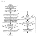
- step S3 the vehicle-side ECU 50C diagnoses the generating feasible power amount (step S9), and amends the lower usage limit according to the generating feasible power amount (step S 10). Subsequently, the vehicle-side ECU 50C determines whether the amount of charge of battery becomes lower than the lower usage limit after it is changed (step S11B). When a negative determination is made, step S11B is repeatedly performed until a positive determination is made. When a position determination is made in step S11B, the flow control proceeds to step S12.
- the electrically driven vehicle 1C diagnoses the generating feasible power amount of the generator unit 11 and amends the lower usage limit according to the generating feasible power amount, as compared with the electrically driven vehicle 1A.
- the lower usage limit may be amended to become smaller as the generating feasible power amount becomes larger.
- the usage start timing of the second battery 30 may be delayed, as compared with the case where the lower usage limit is that before it is amended (that is, the lower usage limit after it is changed).
- the vehicle cruising range can be substantially increased as compared with the electrically driven vehicle 1A because the first battery 12 can be used more efficiently.
- the lower usage limit may be amended to become larger as the generating feasible power amount becomes large.
- the usage start timing of the generator unit 11 may be made earlier, as compared with the case where the usage lower limit is that before it is amended (that is, the usage lower limit after it is changed).
- the usage of the first battery 12 since the usage of the first battery 12 is further restricted, the hard work of the first battery 12 can be further suppressed. As a result, the deterioration of the life of the first battery 12 can be suppressed, as compared with the electrically driven vehicle 1A.
- the electrically driven vehicle 1C is capable of ensuring the appropriate use of the first battery 12 because the first battery 12 can be used appropriately according to the amount of energy capable of really compensating for a shortage of charge of the first battery 12, as compared with the electrically driven vehicle 1A.
- the above-described embodiments are exemplary preferred embodiments of the invention.
- the present invention is not limited to these embodiments but may be carried out with various variations.
- the amount of charge of the first battery 12 is managed by changing the lower usage limit.
- the present invention is not necessarily limited to this, but the management means may manage the amount of charge of the first battery by setting the upper charge limit on the first battery and changing the upper charge limit. In this case, by changing the upper charge limit to a relatively lower level, the occasion for utilizing the generator unit may be increased, so that the deterioration of the life of the first battery can be suppressed. Further, by changing the upper charge limit to a relatively higher level, the first battery can be utilized more efficiently.
- the diagnosis means diagnoses the generating feasible power amount and amends the management of the amount of charge of the first battery according to the generating feasible power amount.
- the diagnosis means further diagnoses the amount of charge of the second battery and the management means may amend the management of the amount of charge of the first battery according to the amount of charge of the second battery.
- the management means may amend the lower usage limit so as to be smaller as the amount of charge of the second battery is larger, or may amend the lower usage limit as the amount of charge of the second battery is larger.
- the second battery 30 is detachably mounted in the vehicle body 10 so as to be interchangeable with the generator unit 11.
- the electrically driven vehicle may be configured to detachably mount both the generator unit and the second battery in parallel.
- the electrically driven vehicle may be configured to detachably mount at least either more than one generator unit or more than one second battery in parallel.
- the diagnosis means may wholly diagnose whether more than one generator unit is capable of generating power or whether more than one second battery can be used.
- the management means may manage the amount of charge of the first battery according to the multiple diagnostic results.
- power supply may be carried out by generating power by a certain generator unit out of among the generator units when the amount of charge of the first battery becomes lower than the lower usage limit.
- the generator unit fails to generate power any more (or when a certain second battery among the second batteries is used and fails to be used any more)
- power supply may be carried out by sequentially another generator unit to generate power or utilizing another second battery.
- the first battery can be utilized appropriately, as compared with the case where the amount of charge of the first battery is managed by the diagnostic result of only one of the generator units and the second batteries.
- the lower usage limit is further amended according to the generating feasible power amount of each of the generator units and the amount of charge of each of the second batteries, whereby the first battery can be utilized more appropriately.
- the various means functionally realized by the vehicle-side ECUs 50A, 50B and 50C may be realized by hardware such as another electronic control device or a dedicated electronic circuit, or a combination thereof.
Abstract
Description
- The present invention relates to electrically driven vehicles, and more particularly, to an electrically driven vehicle in which a generator unit that charges a battery usable for running is detachably mounted.
- Conventionally, there is known an electrically driven vehicle equipped with a battery usable for running. Such an electrically driven vehicle has a limited cruising range that depends on the amount of charge of the battery.
In this regard,Patent Document 1 discloses an electric vehicle in which a first battery is mounted and a generator unit or a second battery is detachably mounted. The electric vehicle disclosed inPatent Document 1 is configured to mount the second battery when the electric vehicle is driven around a charge station or home, and to mount the generator unit when the electric vehicle is driven a long ways.
Patent Document 2 discloses an art that is considered as being relative to the present invention regarding mounting of a generator capable of charging a battery mounted in a vehicle.Patent Documents 3 through 5 disclose arts that are considered as being relative to the present invention in terms of mounting of more than one battery. -
- Patent Document 1: Japanese Patent Application Publication No.
10-117404 - Patent Document 2: Japanese Patent Application Publication No.
2001-211504 - Patent Document 3: Japanese Patent Application Publication No.
2005-237064 - Patent Document 4: Japanese Patent Application Publication No.
11-191902 - Patent Document 5: Japanese Patent Application Publication No.
11-69512 - In the electric vehicle equipped with the battery for running, generally, the amount of charge of the battery may be managed to output an alarm for urging the user to charge the battery when the amount of charge of the battery reduces.
In this regard, in a case where a generator unit is detachably mounted in the electrically driven vehicle, it is conceivable to charge the battery by using the generator unit rather than the outputting of the alarm that urges the user to charge the battery when the electrically driven vehicle has a reduced amount of charge of the battery with the generator unit being really mounted therein. That is, it is conceivable that similar setting values are used for management of the amount of charge of the battery in a case where the generator unit has been mounted and in another case where the generator unit has not been mounted.
However, the case where the generator unit has been mounted does not always need to secure a certain amount of charge of the battery that is estimated to be feasible for retreat running or running up to a charge station.
Further, in the case where the battery is charged by using the generator unit, the operation start timing of the generator unit may affect the appropriate use of the battery. That is, if the operation of the generator unit is started relatively early with respect to the remaining amount of charge of the battery, the battery will not be efficiently utilized accordingly. In contrast, if the operation of the generator unit is started relatively late, the battery will be worked hard accordingly. - In this regard, the electric vehicle disclosed in
Patent Document 1. configured to detachably mount the generator unit does not have a specific consideration about the management of the amount of charge of the first battery between the case where the generator unit has been mounted and the case where the generator unit has not been mounted. Therefore, the electric vehicle disclosed inPatent Document 1 has a problem because the first battery may not be always utilized appropriately. - The present invention was made in view of the above problem and aims to provide an electrically driven vehicle capable of ensuring proper use of a battery when a generator unit is detachably mounted.
- The present invention for solving the above problem is an electrically driven vehicle comprising: a vehicle body; a first battery mounted in the vehicle body and usable for running; a generator unit that is detachably mounted in the vehicle body and charges the first battery; diagnosis means for diagnosing whether the generator unit is capable of generating power; and management means for managing an amount of charge of the first battery according to a diagnostic result of the diagnosis means.
- The present invention is preferably configured so that a lower usage limit is provided for the amount of charge of the first battery; and when the diagnosis means determines that the generator unit is capable of generating power, the management means changes, as a management of the amount of charge of the first battery, the lower usage limit to a level lower than that used when the generator unit is not capable of generating power.
- The present invention is preferably configured so that a second battery usable for running is detachably mounted in the vehicle body; and the diagnosis means diagnoses whether the second battery is usable, and when the diagnosis means determines that the generator unit is capable of generating power, the management means changes, as the management of the amount of charge of the first battery, the lower usage limit to a level lower than that used when the second battery is not usable.
- The present invention is preferably configured so that a lower usage limit is provided for the amount of charge of the first battery; and when the diagnosis means determines that the generator unit is capable of generating power, the management means changes, as a management of the amount of charge of the first battery, the lower usage limit to a level higher than that used when the generator unit is not capable of generating power.
- The present invention is preferably configured so that a second battery usable for running is detachably mounted in the vehicle body; and the diagnosis means diagnoses whether the second battery is usable, and when the diagnosis means determines that the generator unit is capable of generating power, the management means changes, as the management of the amount of charge of the first battery, the lower usage limit to a level higher than that used when the second battery is not usable.
- The present invention is preferably configured so that the diagnosis means diagnoses a generating feasible power amount of the generator unit in a process of diagnosing whether the generator unit is capable of generating power; and the management means further amend the management of the amount of charge of the first battery according to the generating feasible power amount.
- According to the present invention, it is possible to ensure proper use of the battery when the generator unit is detachably mounted.
-
-
FIG. 1 is a diagram of a schematic structure of an electrically driven vehicle in accordance with a first embodiment; -
FIG. 2 is a diagram of a generator unit in accordance with the first embodiment; -
FIG. 3 is a flowchart of an operation of a vehicle-side ECU (Electric Control Unit) in accordance withEmbodiment 1; -
FIG. 4 is a diagram of a schematic structure of an electrically driven vehicle in accordance with a second embodiment; -
FIG. 5 is a flowchart of an operation of a vehicle-side ECU in accordance withEmbodiment 2; and -
FIG. 6 is a flowchart of an operation of a vehicle-side ECU in accordance withEmbodiment 3. - Now, a description is given of modes for carrying out the invention in conjunction with the drawings.
- As illustrated in
FIG. 1 , an electrically driven vehicle 1A has avehicle body 10 in which agenerator unit 11, abattery 12, and anelectric motor 13 are mounted. The electrically driven vehicle 1A is configured so that thegenerator unit 11 is detachably mounted. The electrically driven vehicle 1A capable of detachably installing thegenerator unit 11 can be operated in a state in which thegenerator unit 11 is not mounted and is electrically disconnected. - The
generator unit 11 is an engine driven type of generator unit, and is equipped, as illustrated inFIG. 2 , with anengine 111, agenerator 112,a generator-unit-side ECU 113, and a generator-unit-side fuel tank 114. Theengine 111 drives thegenerator 112, which generates alternating current. Then, the alternating current thus generated is converted to direct current by a not-illustrated rectifying circuit before being charged in thebattery 12. The generator-unit-side ECU 113 is provided for primarily controlling theengine 111. - As illustrated in
FIG. 1 , thebattery 12 is a direct current battery, and is electrically and detachably connected to thegenerator unit 11 via high-voltage system wires that are power-system wires. Energy generated by thegenerator unit 11 is stored in thebattery 12 via the high-voltage system wires. Thebattery 12 may be configured to have multiple batteries having a rated DC voltage of 12 V connected in series, for example. Theelectric motor 13 is a source for running, and is a DC motor. Theelectric motor 13 is supplied with energy from thebattery 12, and rotates anoutput shaft 14. Then, the rotary output is transmitted, via atransmission 15, to a pair of right and leftrear wheels 2, which are driving wheels, so that therear wheels 2 can be driven. As described above, the electrically driven vehicle 1A is a series hybrid type of electrically driven vehicle. - The electrically driven vehicle 1A is equipped, in addition to the pair of right and left
rear wheels 2 of the driving wheels, with a pair of right and leftfront wheels 3 that are steering wheels, ahandle 4 for manually steering thefront wheels 3, anacceleration pedal 5 for changing the number of revolutions of theelectric motor 13, a brake pedal 6 and abrake unit 7 for braking the vehicle, anddrum brakes 8 coupled with the brake pedal 6 by wires, joined to thebrake unit 7 and provided to thefront wheels 3 and therear wheels 2. Theacceleration pedal 5 is provided with an acceleration position sensor 26 that senses the amount of depression of theacceleration pedal 5, and the brake pedal 6 is provided with abrake switch 62 that senses whether the brake pedal 6 is depressed or not. - The electrically driven vehicle 1A is further provided with a
key switch 21, and ageneration switch 22. Thekey switch 21 and thegeneration switch 22 are switches that enable selective switching operation between ON and OFF. Thekey switch 21 is operation means for making an operation request to theelectric motor 13. Specifically, when thekey switch 21 is ON, the operation request to theelectric motor 13 is made. When thekey switch 21 is OFF, the operation request to theelectric motor 13 is not made. Thegeneration switch 22 is operation means for making a request to thegenerator unit 11. Specifically, when thegeneration switch 22 is ON, the operation request to thegenerator unit 11 is made. When thegeneration switch 22 is OFF, the operation request to thegenerator unit 11 is not made. Thekey switch 21 and thegeneration switch 22 are provided on a not-illustrated instrument panel. - As illustrated in
FIG. 1 , the electrically driven vehicle 1A is equipped with a vehicle-side ECU 50A, which is a first control unit. The vehicle-side ECU 50A is equipped with a microcomputer composed of a CPU, a ROM, a RAM and so on, and an input/output circuit, which are not illustrated. The generator-unit-side ECU 113, which is a second control unit, is configured similarly. The generator unit 11 (more specifically, the generator-unit-side ECU 113) is electrically and detachably connected to the vehicle-side ECU 50A. In this regard, the vehicle-side ECU 50A and thegenerator unit 11 are connected together via low-voltage system wires, which are control-system wires.
Various objects to be controlled such as theelectric motor 13 are electrically connected to the vehicle-side ECU 50A, and further, various sensors and switches such as thekey switch 21, theacceleration position sensor 61, thebrake switch 62, and afirst mount sensor 63 that is a state sensing means capable of detecting whether thegenerator unit 11 is mounted or not are electrically connected thereto.
Afirst battery 12 is electrically connected to the vehicle-side ECU 50A in order to detect the amount of charge of the battery. The electrically driven vehicle 1A has a lower usage limit to the amount of charge of thefirst battery 12. - The ROM is configured to store a program in which various processes executed by the CPU are described and to store map data. The CPU executes the processes on the basis of the program stored in the ROM while using a temporary memory area ensured in the RAM as necessary, so that various control means, determination means, detection means and calculation means can be functionally realized in the
ECU 50A on the vehicle side and theECU 113 on the generator unit side. - The vehicle-
side ECU 50A functionally realizes diagnosis means for diagnosing whether thegenerator unit 11 can generate power.
In the step of diagnosing whether thegenerator unit 11 can generate power, the diagnosis means is realized to diagnose the generating feasible state of thegenerator unit 11.
Specifically, the diagnosis means may be realized to diagnose the generating feasible state of thegenerator unit 11 by determining whether thegenerator unit 11 has been mounted.
The diagnosis means may be realized to diagnose the generating feasible state of thegenerator unit 11 by determining whether a not-illustrated interlock device provided for detecting whether the mounted state of thegenerator unit 11 has a regular state (for example, a fixing confirmation device of thegenerator unit 11, or a lock confirmation device of a door for a storage space for the generator unit 11), or determining whether the electrically connected state of thegenerator unit 11 has any abnormality, or by determining whether the mechanically connected state of thegenerator unit 11 has any abnormality, or determining whether thegenerator unit 11 has any abnormality such as failure, or a combination of the above determinations. [0024] Specifically, the diagnosis means is realized to diagnose the generating feasible state of thegenerator unit 11 by using a combination of determinations.
More specifically, the diagnosis means is realized to determine that thegenerator unit 11 is capable of generating power when the diagnostic results show that thegenerator unit 11 has been mounted and the interlock device detects the regular state and that the amount of fuel for thegenerator unit 11 is equal to or larger than a predetermined level and the electric and mechanical connections of thegenerator unit 11 have no abnormality, and show that thegenerator unit 11 has no abnormality. - In the step of diagnosing the generation feasible state of the
generator unit 11. the diagnosis means may be realized to include, as a basic determination, at least the step of determining whether thegenerator unit 11 has been mounted. However, the diagnosis is not limited to the above, but may include, as a basic determination, the step of determining whether the electric and mechanical connections of thegenerator unit 11 have any abnormality, whereby the determination as to whether thegenerator unit 11 has been mounted may be made indirectly. - The vehicle-
side ECU 50A functionally realizes management means for performing a management of the amount of charge of thefirst battery 12 according to the diagnostic results of the diagnosis means, for example.
Specifically, the management means is realized to change the lower usage limit as a management of the amount of charge of thefirst battery 12 when the diagnosis means determines that thegenerator unit 11 is capable of generating power. Specifically, the predetermined lower usage limit (hereinafter, referred to as preset lower usage limit) is defined for a case where thegenerator unit 11 is not capable of generating power. More specifically, the preset lower usage limit is the amount of charge stored in the battery that is estimated to be feasible for retreat running or running up to a charge station.
In the process of changing the lower usage limit, specifically, the management means may be realized to set the lower usage limit to a level lower than that for the case where thegenerator unit 11 is not capable of generating power. Also, the management means may be realized to set the lower usage limit to a level higher than that for the case where thegenerator unit 11 is not capable of generating power. - The vehicle-
side ECU 50A functionally realizes alarm control means that outputs an alarm when the amount of charge of thefirst battery 12 becomes lower than the lower usage limit. Specifically, the alarm control means is realized to output the alarm that notifies the user that the amount of charge of thefirst battery 12 becomes lower than the lower usage limit when thegenerator unit 11 is not capable of generating power and the amount of charge of thefirst battery 12 becomes lower than the lower usage limit. Specifically, the lower usage limit in this case is the preset lower usage limit.
The vehicle-side ECU 50A functionally realizes output control means for outputting an operation request to thegenerator unit 11 when thegenerator unit 11 is capable of generating power and the amount of charge of the battery becomes lower than the lower use limit. In this case, the lower usage limit is a changed lower usage limit. - A description is now given of an operation of the vehicle-
side ECU 50A in conjunction with a flowchart ofFIG. 3 . The vehicle-side ECU 50A diagnoses the generating feasible state of the generator unit 11 (step S1), and determines whether thegenerator unit 11 is capable of generating power (step S2). When a negative determination is made, the vehicle-side ECU 50A determines whether thegenerator unit 11 has not been mounted (step S4). When a positive determination is made, the flow process is ended. In this case, an alarm that indicates an abnormality of thegenerator unit 11 may be output. In contrast, a negative determination is made in step S4, the vehicle-side ECU 50A determines whether the amount of charge of the battery becomes the lower usage limit (step S21). When a negative determination is made, step S21 is repeatedly performed until a positive determination is made. When a positive determination is made in step S21, the vehicle-side ECU 50A outputs an alarm showing that the amount of charge of the battery becomes lower than the lower usage limit (step S22). - In contrast, when a positive determination is made in step S2, the vehicle-
side ECU 50A changes the lower usage limit (step S3). Subsequently, the vehicle-side ECU 50A determines whether the amount of charge of the battery becomes lower than the changed lower usage limit (step S11A). When a negative decision is made, step S11A is repeatedly performed until a positive determination is made. In contrast, when a positive determination is made in step S11A, the vehicle-side ECU 50A outputs the operation request to the generator unit 11 (step S12). Thus, thegenerator unit 11 starts generating power. - A description is now given of functions and effects of the electrically driven vehicle 1A. The electrically driven vehicle 1A diagnoses whether the
generator unit 11 is capable of generating power, and performs the management of the amount of charge of thefirst battery 12 according to the diagnostic results.
When it is determined that thegenerator unit 11 is capable of generating power, the electrically driven vehicle 1A is capable of changing the lower usage limit to a level lower than that used when thegenerator unit 11 is not capable of generating power. In this case, the electrically driven vehicle 1A utilizes thefirst battery 12 until the amount of charge of the battery becomes lower than the lower usage limit that has been changed to the lower level. Therefore, the operation start timing of thegenerator unit 11 can be delayed, as compared with the case where the lower usage limit is the preset lower usage limit. Thus, thefirst battery 12 can be used more efficiently. Since thefirst battery 12 can be used more efficiently, the vehicle cruising range can be increased substantially. - When it is determined that the
generator unit 11 is capable of generating power, the electrically driven vehicle 1A may change the lower usage limit to a level higher than that used when thegenerator unit 11 is not capable of generating power. In this case, thefirst battery 12 is utilized until the amount of charge of the battery becomes lower than the lower usage limit that has been changed to the higher level. Therefore, the operation start timing of thegenerator unit 11 can be made earlier, as compared with the case where the lower usage limit is the preset lower usage limit. Therefore, in this case, the usage of thefirst battery 12 is further restricted. Since the usage of thefirst batters 12 is further restricted, hard working of thefirst battery 12 can be suppressed and the deterioration of the life of thefirst battery 12 can be suppressed.
Thus, the electrically driven vehicle 1A is capable of ensuring the appropriate use of thefirst battery 12 when thegenerator unit 11 is detachably mounted. - The electrically driven vehicle 1A diagnoses the generating feasible state of the
generator unit 11 by making a determination based on the combination of multiple determinations. It is thus possible to appropriately prevent the lower usage limit from being changed although thegenerator unit 11 is not really capable of generating power, as compared with the case where only the determination as to whether thegenerator unit 11 has been mounted is made.
Since the electrically driven vehicle 1A is capable of preventing the lower usage limit from being changed inappropriately, thefirst battery 12 can be used appropriately. - The lower usage limit after it is changed may be predetermined according to a required performance of the electrically driven vehicle 1A, which may give priority to the cruising range of the vehicle or the life of the
first battery 12 or may optimize the balance between these items.
The lower usage limit after it is changed may be determined by providing recording means for recording the usage history of the vehicle and referring to the usage history of the vehicle recorded by recording means. This case is preferable because more appropriate effects based on the usage tendency of the vehicle are obtained. In this case, the initial value of the lower usage limited after it is changed may be predetermined according to the required performance of the electrically driven vehicle 1A, or may be predetermined to the preset lower usage limit taking into consideration the fact that the usage history is not present initially.
The lower usage limit after it is changed may be determined by providing operation means capable of adjusting or stepwisely selecting the lower usage limit after it is changed and referring to an operation applied to the operation means. This case is preferable because effects that the user wishes are obtained. - As illustrated in
FIG. 4 , an electrically driven vehicle 1B in accordance with the present embodiment is substantially the same as the electrically driven vehicle 1A except that asecond battery 30 usable for running is further mounted in thevehicle body 10 detachably, and asecond mount sensor 64 is further provided and that a vehicle-side ECU 50B is substituted for the vehicle-side ECU 50A. - The
second battery 30 is configured to be mounted so as to be interchangeable with thegenerator unit 11. Thus, specifically, thesecond battery 30 is detachably mounted in the same position in thevehicle body 10 as that of thegenerator unit 11.
Thesecond mount sensor 64 is provided in thevehicle body 10 as state sensing means capable of detecting the mounting/not-mounting of thesecond battery 30 by sensing the mounted state of thesecond battery 30. Thefirst mount sensor 63 is provided so as not to detect the mounting/not-mounting of thesecond battery 30, and thesecond mount sensor 64 is provided so as not to detect the mounting/not-mounting of thegenerator unit 11.
The vehicle-side ECU 50B is substantially the same as the vehicle-side ECU 50A except that diagnosis means and management means are realized as described below, and power supply switch means is functionally realized further and that thesecond battery 30 is electrically connected for the purpose of detecting the amount of charge of the battery and thesecond mount sensor 64 is electrically connected further. - The vehicle-
side ECU 50B is realized so that the diagnosis means diagnoses whether thesecond battery 30 is usable.
In the process of diagnosing whether thesecond battery 30 is usable, the diagnosis means is realized to diagnose the usable state of thesecond battery 30.
In this regard, the diagnosis means may be realized to diagnose the usable state of thesecond battery 30 by determining whether thesecond battery 30 has been mounted.
The diagnosis means may be realized to diagnose the state of power generation of thegenerator unit 11 by determining whether a not-illustrated interlock device provided for detecting whether the mounted state of thegenerator unit 11 has a regular state (for example, a fixing confirmation device of thesecond battery 30, or a lock confirmation device of a door for a storage space for the second battery 30), or determining whether the amount of charge of thesecond battery 30 is sufficient (equal to or larger than a predetermined volume), or determining whether the electrically connected state of thesecond battery 30 has any abnormality, or by determining whether the mechanically connected state of thesecond battery 30 has any abnormality, or determining whether thesecond battery 30 has any abnormality such as failure, or a combination of the above determinations. - Specifically, the diagnosis means is realized to diagnose the usable state of the
second battery 30 by using a combination of determinations.
More specifically, the diagnosis means is realized to determine that thesecond battery 30 is usable when the diagnostic results show that thesecond battery 30 has been mounted and the interlock device detects the regular state and that the amount of charge of thesecond battery 30 is equal to or larger than the predetermined level and the electric connection of thesecond battery 30 has no abnormality, and show that thesecond battery 30 is usable. - In the process of diagnosing the generating feasible state of the
second battery 30, the diagnosis means may be realized to include, as a basic determination, at least the step of determining whether thesecond battery 30 has been mounted. However, the diagnosis is not limited to the above, but may include, as a basic determination, the step of determining whether the electric connection of thesecond battery 30 has any abnormality, whereby the determination as to whether thesecond battery 30 has been mounted may be made indirectly. - The vehicle-
side ECU 50B functionally realizes management means for performing a management of the amount of charge of thefirst battery 12 according to the diagnostic results of thesecond battery 30.
Specifically, the management means is realized to change the lower usage limit as a management of the amount of charge of thefirst battery 12 when the diagnosis means determines that thesecond battery 30 is usable. In the electrically driven vehicle 1B, the present lower usage limit is the lower usage limit defined when thegenerator unit 11 is not capable of generating power and thesecond battery 30 is not usable.
In the process of changing the lower usage limit, specifically, the management means may be realized to set the lower usage limit to a level lower than that for the case where thesecond battery 30 is not usable. Also, the management means may be realized to set the lower usage limit to a level higher than that for the case where thesecond battery 30 is not usable.
The power supply switch means is realized to perform a control of switching the power supply from thefirst battery 12 to thesecond battery 30 when thesecond battery 30 is usable and the amount of charge of thefirst battery 12 becomes lower than the lower usable limit. In this case, the lower usable limit is that after it is changed. - A description is now given of an operation of the vehicle-
side ECU 50B in conjunction with a flowchart ofFIG. 5 . The present flowchart is the same as that ofFIG. 3 except that steps S5 through S8 and steps S31 and 32 are added. Therefore, these steps are specifically described. Subsequent to a positive determination in step S4, the vehicle-side ECU 50B diagnoses the usable state of the second battery 30 (step S5), and determines whether thesecond battery 30 is usable or not (step S6). When a negative determination is made in step S6, the vehicle-side ECU 50B determines whether thesecond battery 30 is not mounted (step S8). When a positive determination is made, the flow process is ended. In this case, an alarm that notifies the user of an abnormality of thesecond battery 30 may be output. In contrast, when a negative determination is made in step S8, the process proceeds to step S21. - In contrast, when a positive determination is made in step S6, the vehicle-
side ECU 50B changes the lower usage limit (step S7). Subsequently, the vehicle-side ECU 50B determines whether the amount of charge of thefirst battery 12 becomes lower than the lower usage limit (step S31). When a negative determination is made, step S31 is repeatedly performed until a position determination is made. In contrast, when a positive determination is made in step S31, the vehicle-side ECU 50B switches the power supply from thefirst battery 12 to the second battery 30 (step S32). - A description is now given of functions and effects of the electrically driven vehicle 1B. The electrically driven vehicle 1B is configured to detachably mount the
second battery 30 usable for running in addition to thegenerator unit 11. Thus, the electrically driven vehicle 1B is capable of improving the convenience because a shortage of charge of thefirst battery 12 may be compensated for by not only thegenerator unit 11 but also thesecond battery 30.
In addition to thegenerator unit 11, the electrically driven vehicle 1B is configured to detachably mount thesecond battery 30 so as to be interchangeable with thegenerator unit 11. Thus, thesecond battery 30 can be detachably mounted in thevehicle body 10 without a great change of the vehicle body, whereby the electrically driven vehicle 1B has a cost advantage. - In the electrically driven vehicle 1B configured to detachably mount the
second battery 30 in addition to thegenerator unit 11, in order to ensure the appropriate use of thefirst battery 12, the usable state of thesecond battery 30 is diagnosed and the amount of charge of thefirst battery 12 is managed.
When it is determined that thesecond battery 30 is usable, the lower usable limit can be changed to a level lower than that used when thesecond battery 30 is not usable. In this case, the usage start timing of thesecond battery 30 can be delayed, as compared with the case where the usage lower limit is the preset lower usage limit. Thus, thefirst battery 12 is used more efficiently, and the vehicle cruising range can be increased substantially. - When it is determined that the
second battery 30 is usable, the lower usable limit can be changed to a higher lower than that used when thesecond battery 30 is not usable. In this case, the operation start timing of thegenerator unit 11 can be made earlier. Thus, the usage of thefirst battery 12 can be restricted more strongly, so that the hard working of thefirst battery 12 can be suppressed and the deterioration of the life of thefirst battery 12 can be suppressed.
Thus, the electrically driven vehicle 1B is capable of ensuring the appropriate use of thefirst battery 12 although the second battery is detachably mounted further, as compared with the electrically driven vehicle 1A. - The electrically driven vehicle 1B diagnoses the usable state of the
second battery 30 by the combination of multiple determinations. Thus, it is thus possible to appropriately prevent the lower usage limit from being changed although thesecond battery 30 is not really usable, as compared with the case where only the determination as to whether thesecond battery 30 has been mounted is made, for example.
Since the electrically driven vehicle 1B is capable of preventing the lower usage limit from being changed inappropriately, thefirst battery 12 can be used appropriately.
In the electrically driven vehicle 1B, the lower usage limit after it is changed may be set in a manner similar to that for the electrically driven vehicle 1A. - An electrically driven vehicle 1C in accordance with the present embodiment is substantially the same as the electrically driven vehicle 1A except that a vehicle-side ECU 50C is substituted for the vehicle-
side ECU 50A. The vehicle-side ECU 50C is substantially the same as the vehicle-side ECU 50A except that diagnosis means and management means are realized as described below. Therefore, an illustration of the electrically driven vehicle 1C is omitted. A similar change may be applied to the electrically driven vehicle 1B previously described inEmbodiment 2. - The vehicle-side ECU 50C is realized to further diagnose the generating feasible power amount of the
generator unit 11.
Specifically, the diagnosis means may be realized to diagnose the generating feasible power amount of thegenerator unit 11 on the basis of the remaining amount of fuel of thegenerator unit 11, the type of fuel, or operation conditions of thegenerator unit 11 such as conditions with the rated power or conditions with the maximum power.
The diagnosis means is realized to diagnose the generating feasible power amount of thegenerator unit 11 when diagnosing that thegenerator unit 11 is capable of generating power. - In the vehicle-side ECU 50C, when the diagnosis means determines that the
generator unit 11 can generate power and diagnoses the generating feasible power amount, the management means is realized o further amend the management of the amount of charge of thefirst battery 12 according to the generating feasible power amount.
Specifically, the management means is realized to amend the management of the amount of charge of thefirst battery 12 by amending the lower usage limit according to the generating feasible power amount. In this case, specifically, the lower usage limit is that after it is changed.
In the change of the lower usage limit, the management means may be realized to amend the lower usage limit in such a manner that the lower usage limit becomes smaller as the generating feasible power amount becomes large. The management mans may be realized to amend the lower usage limit in such a manner that the lower usage limit becomes larger as the generating feasible power amount becomes large. - An operation of the electrically driven vehicle 1C is described in conjunction with a flowchart of
FIG. 6 . The present flowchart is the same as the flowchart ofFIG. 3 except that steps S9 and S10 are added, and step S11B is substituted for step S11A. Therefore, these steps are specifically described here. Subsequent to step S3, the vehicle-side ECU 50C diagnoses the generating feasible power amount (step S9), and amends the lower usage limit according to the generating feasible power amount (step S 10). Subsequently, the vehicle-side ECU 50C determines whether the amount of charge of battery becomes lower than the lower usage limit after it is changed (step S11B). When a negative determination is made, step S11B is repeatedly performed until a positive determination is made. When a position determination is made in step S11B, the flow control proceeds to step S12. - A description is now given of functions and effects of the electrically driven vehicle 1C. The electrically driven vehicle 1C diagnoses the generating feasible power amount of the
generator unit 11 and amends the lower usage limit according to the generating feasible power amount, as compared with the electrically driven vehicle 1A.
In the electrically driven vehicle I C, the lower usage limit may be amended to become smaller as the generating feasible power amount becomes larger. In this case, the usage start timing of thesecond battery 30 may be delayed, as compared with the case where the lower usage limit is that before it is amended (that is, the lower usage limit after it is changed). Thus, the vehicle cruising range can be substantially increased as compared with the electrically driven vehicle 1A because thefirst battery 12 can be used more efficiently. - In the electrically driven vehicle 1C, the lower usage limit may be amended to become larger as the generating feasible power amount becomes large. In this case, the usage start timing of the
generator unit 11 may be made earlier, as compared with the case where the usage lower limit is that before it is amended (that is, the usage lower limit after it is changed). In this case, since the usage of thefirst battery 12 is further restricted, the hard work of thefirst battery 12 can be further suppressed. As a result, the deterioration of the life of thefirst battery 12 can be suppressed, as compared with the electrically driven vehicle 1A.
Thus, the electrically driven vehicle 1C is capable of ensuring the appropriate use of thefirst battery 12 because thefirst battery 12 can be used appropriately according to the amount of energy capable of really compensating for a shortage of charge of thefirst battery 12, as compared with the electrically driven vehicle 1A. - The above-described embodiments are exemplary preferred embodiments of the invention. However, the present invention is not limited to these embodiments but may be carried out with various variations.
For example, in the above-described embodiments, the amount of charge of thefirst battery 12 is managed by changing the lower usage limit.
However, the present invention is not necessarily limited to this, but the management means may manage the amount of charge of the first battery by setting the upper charge limit on the first battery and changing the upper charge limit.
In this case, by changing the upper charge limit to a relatively lower level, the occasion for utilizing the generator unit may be increased, so that the deterioration of the life of the first battery can be suppressed. Further, by changing the upper charge limit to a relatively higher level, the first battery can be utilized more efficiently. - In the above-described
Embodiment 3, the diagnosis means diagnoses the generating feasible power amount and amends the management of the amount of charge of the first battery according to the generating feasible power amount. However, the present invention is not necessarily limited to this, but the diagnosis means further diagnoses the amount of charge of the second battery and the management means may amend the management of the amount of charge of the first battery according to the amount of charge of the second battery.
In this case, the management means may amend the lower usage limit so as to be smaller as the amount of charge of the second battery is larger, or may amend the lower usage limit as the amount of charge of the second battery is larger. - In the above-described
Embodiment 2, thesecond battery 30 is detachably mounted in thevehicle body 10 so as to be interchangeable with thegenerator unit 11.
However, the present invention is not limited to this, but the electrically driven vehicle may be configured to detachably mount both the generator unit and the second battery in parallel. The electrically driven vehicle may be configured to detachably mount at least either more than one generator unit or more than one second battery in parallel.
In this case, the diagnosis means may wholly diagnose whether more than one generator unit is capable of generating power or whether more than one second battery can be used. The management means may manage the amount of charge of the first battery according to the multiple diagnostic results. - In this case, power supply may be carried out by generating power by a certain generator unit out of among the generator units when the amount of charge of the first battery becomes lower than the lower usage limit. After that, when the generator unit fails to generate power any more (or when a certain second battery among the second batteries is used and fails to be used any more), power supply may be carried out by sequentially another generator unit to generate power or utilizing another second battery.
Thus, the first battery can be utilized appropriately, as compared with the case where the amount of charge of the first battery is managed by the diagnostic result of only one of the generator units and the second batteries. In this case, the lower usage limit is further amended according to the generating feasible power amount of each of the generator units and the amount of charge of each of the second batteries, whereby the first battery can be utilized more appropriately. - In the above-described embodiments, the various means functionally realized by the vehicle-
side ECUs -
- 1A, 1B, 1C
- electrically driven vehicle
- 10
- vehicle body
- 11
- generator unit
- 111
- engine
- 12
- first battery
- 30
- second battery
- 50A, 50B, 50C
- vehicle-side ECU
Claims (6)
- An electrically driven vehicle comprising:a vehicle body;a first battery mounted in the vehicle body and usable for running;a generator unit that is detachably mounted in the vehicle body and charges the first battery;diagnosis means for diagnosing whether the generator unit is capable of generating power; andmanagement means for performing a management of an amount of charge of the first battery according to a diagnostic result of the diagnosis means.
- The electrically driven vehicle according to claim 1, wherein:a lower usage limit is provided for the amount of charge of the first battery; andwhen the diagnosis means determines that the generator unit is capable of generating power, the management means changes, as the management of the amount of charge of the first battery, the lower usage limit to a level lower than that used when the generator unit is not capable of generating power.
- The electrically driven vehicle according to claim 2, wherein:a second battery usable for running is detachably mounted in the vehicle body; andthe diagnosis means diagnoses whether the second battery is usable, and when the diagnosis means determines that the generator unit is capable of generating power, the management means changes, as the management of the amount of charge of the first battery, the lower usage limit to a level lower than that used when the second battery is not usable.
- The electrically driven vehicle according to claim 1, wherein:a lower usage limit is provided for the amount of charge of the first battery; andwhen the diagnosis means determines that the generator unit is capable of generating power, the management means changes, as the management of the amount of charge of the first battery, the lower usage limit to a level higher than that used when the generator unit is not capable of generating power.
- The electrically driven vehicle according to claim 4, wherein:a second battery usable for running is detachably mounted in the vehicle body; andthe diagnosis means diagnoses whether the second battery is usable, and when the diagnosis means determines that the generator unit is capable of generating power, the management means changes, as the management of the amount of charge of the first battery, the lower usage limit to a level higher than that used when the second battery is not usable.
- The electrically driven vehicle according to any one of claims 1 through 5, wherein:the diagnosis means diagnoses a generating feasible power amount of the generator unit in a process of diagnosing whether the generator unit is capable of generating power; andthe management means further amend the management of the amount of charge of the first battery according to the generating feasible power amount.
Applications Claiming Priority (1)
| Application Number | Priority Date | Filing Date | Title |
|---|---|---|---|
| PCT/JP2010/050393 WO2011086681A1 (en) | 2010-01-15 | 2010-01-15 | Electrically driven vehicle |
Publications (3)
| Publication Number | Publication Date |
|---|---|
| EP2524835A1 true EP2524835A1 (en) | 2012-11-21 |
| EP2524835A4 EP2524835A4 (en) | 2015-07-08 |
| EP2524835B1 EP2524835B1 (en) | 2016-11-16 |
Family
ID=44303985
Family Applications (1)
| Application Number | Title | Priority Date | Filing Date |
|---|---|---|---|
| EP10843040.6A Not-in-force EP2524835B1 (en) | 2010-01-15 | 2010-01-15 | Electrically driven vehicle |
Country Status (5)
| Country | Link |
|---|---|
| US (1) | US8892282B2 (en) |
| EP (1) | EP2524835B1 (en) |
| JP (1) | JP5316652B2 (en) |
| CN (1) | CN102695627B (en) |
| WO (1) | WO2011086681A1 (en) |
Families Citing this family (6)
| Publication number | Priority date | Publication date | Assignee | Title |
|---|---|---|---|---|
| JP5606488B2 (en) * | 2012-04-19 | 2014-10-15 | 三菱電機株式会社 | In-vehicle power supply |
| CN103901825A (en) * | 2012-12-27 | 2014-07-02 | 博世汽车部件(苏州)有限公司 | Electronic control unit of electric scooter and electric scooter using the electronic control unit |
| DE102018102211B3 (en) * | 2018-02-01 | 2019-09-19 | Dr. Ing. H.C. F. Porsche Aktiengesellschaft | Battery system for a battery powered electric vehicle and method for utilizing a remaining range thereof |
| US11641572B2 (en) * | 2019-06-07 | 2023-05-02 | Anthony Macaluso | Systems and methods for managing a vehicle's energy via a wireless network |
| JP7276113B2 (en) | 2019-12-19 | 2023-05-18 | トヨタ自動車株式会社 | vehicle, vehicle control system |
| JP7272258B2 (en) | 2019-12-19 | 2023-05-12 | トヨタ自動車株式会社 | vehicle |
Family Cites Families (20)
| Publication number | Priority date | Publication date | Assignee | Title |
|---|---|---|---|---|
| JP3050073B2 (en) * | 1994-12-22 | 2000-06-05 | トヨタ自動車株式会社 | Power generation control device for hybrid electric vehicles |
| JPH10117404A (en) * | 1996-10-11 | 1998-05-06 | Nippon Fuaiaa Utsudo Kk | Electric vehicle provided with generator |
| JPH1169512A (en) | 1997-06-12 | 1999-03-09 | Shigeo Tanahashi | Electric car |
| JPH11191902A (en) | 1997-10-24 | 1999-07-13 | Shigeo Tanahashi | Electric vehicle |
| JPH11341608A (en) * | 1998-05-29 | 1999-12-10 | Honda Motor Co Ltd | Electric vehicle |
| JP2001211504A (en) * | 2000-01-26 | 2001-08-03 | Shigeo Tanahashi | Electric vehicle |
| JP2002017001A (en) * | 2000-06-30 | 2002-01-18 | Okamura Kenkyusho:Kk | Charging and controlling method by electricity storing device in hybrid electric vehicle |
| JP2003286000A (en) * | 2002-03-29 | 2003-10-07 | Aichi Corp | Battery type working vehicle |
| JP3587254B2 (en) * | 2002-07-08 | 2004-11-10 | トヨタ自動車株式会社 | Vehicle control device |
| JP2005151721A (en) * | 2003-11-17 | 2005-06-09 | Nissan Motor Co Ltd | Controller of vehicle |
| JPWO2005068245A1 (en) * | 2004-01-16 | 2007-12-27 | ヤマハ発動機株式会社 | Hybrid vehicle |
| JP2005237064A (en) * | 2004-02-18 | 2005-09-02 | Autech Japan Inc | Vehicle controller |
| GB2422717B (en) | 2005-02-01 | 2007-11-14 | Intelligent Energy Ltd | Detachable fuel cell power unit for vehicle applications |
| JP2007043881A (en) * | 2005-08-03 | 2007-02-15 | Shinichi Shioda | Electric vehicle (ev) provided with generator particularly for charging on the same axle on which motor is mounted |
| JP4877625B2 (en) | 2005-11-07 | 2012-02-15 | 義明 小宮山 | In-vehicle power generation and storage equipment for automobiles |
| JP2008029071A (en) * | 2006-07-19 | 2008-02-07 | Honda Motor Co Ltd | Motor-driven vehicle |
| US7659698B2 (en) * | 2006-10-02 | 2010-02-09 | Ford Global Technologies, Llc | System and method for controlling a state of charge of an energy storage system |
| JP2008296669A (en) * | 2007-05-30 | 2008-12-11 | Daihatsu Motor Co Ltd | Charging apparatus for hybrid automobile |
| TWI445240B (en) * | 2007-08-30 | 2014-07-11 | Yamaha Motor Co Ltd | Fuel cell system and control method therefor |
| JP4577413B2 (en) * | 2008-06-20 | 2010-11-10 | トヨタ自動車株式会社 | vehicle |
-
2010
- 2010-01-15 WO PCT/JP2010/050393 patent/WO2011086681A1/en active Application Filing
- 2010-01-15 US US13/520,951 patent/US8892282B2/en not_active Expired - Fee Related
- 2010-01-15 EP EP10843040.6A patent/EP2524835B1/en not_active Not-in-force
- 2010-01-15 JP JP2011549817A patent/JP5316652B2/en not_active Expired - Fee Related
- 2010-01-15 CN CN201080060745.7A patent/CN102695627B/en not_active Expired - Fee Related
Non-Patent Citations (1)
| Title |
|---|
| See references of WO2011086681A1 * |
Also Published As
| Publication number | Publication date |
|---|---|
| WO2011086681A1 (en) | 2011-07-21 |
| US20120330486A1 (en) | 2012-12-27 |
| EP2524835A4 (en) | 2015-07-08 |
| JP5316652B2 (en) | 2013-10-16 |
| CN102695627B (en) | 2014-10-22 |
| US8892282B2 (en) | 2014-11-18 |
| EP2524835B1 (en) | 2016-11-16 |
| CN102695627A (en) | 2012-09-26 |
| JPWO2011086681A1 (en) | 2013-05-16 |
Similar Documents
| Publication | Publication Date | Title |
|---|---|---|
| KR100792893B1 (en) | Method for control power generating point for hev | |
| KR101558363B1 (en) | Method and system for controlling charging and discharging of battery | |
| EP2524835B1 (en) | Electrically driven vehicle | |
| JP5966376B2 (en) | Control device for hybrid vehicle | |
| KR101761539B1 (en) | Hybrid vehicle | |
| US7617895B2 (en) | Method of determination of driving mode of hybrid vehicle | |
| CN107852002B (en) | Method and system for balancing battery pack | |
| CN103998312A (en) | Method and device for power management of an electrical drive for a hybrid vehicle | |
| CN110316176A (en) | Control device | |
| EP2402204B1 (en) | Electrically driven vehicle | |
| US9868434B2 (en) | Vehicle and control method for vehicle | |
| JP2013060056A (en) | Control device for hybrid vehicle | |
| JP5411237B2 (en) | Control device for hybrid vehicle | |
| KR100906872B1 (en) | Method for battery performance improvement and SOC reset of HEV | |
| US11198368B2 (en) | Vehicular charging control system | |
| JP5293160B2 (en) | Vehicle control device | |
| JP5267882B2 (en) | Power generation control device | |
| JP5672251B2 (en) | Vehicle power supply control device | |
| EP2500204B1 (en) | Electrically driven vehicle | |
| JP2021059171A (en) | Electric vehicle control device | |
| JP3175431B2 (en) | Power generation control device for hybrid electric vehicle | |
| US20220290645A1 (en) | Engine start control device | |
| JP6958458B2 (en) | Electric car | |
| JP5365492B2 (en) | Abnormality diagnosis device for power generation device and electrically driven vehicle | |
| JP2011223671A (en) | Hybrid vehicle circuit system |
Legal Events
| Date | Code | Title | Description |
|---|---|---|---|
| PUAI | Public reference made under article 153(3) epc to a published international application that has entered the european phase |
Free format text: ORIGINAL CODE: 0009012 |
|
| 17P | Request for examination filed |
Effective date: 20120706 |
|
| AK | Designated contracting states |
Kind code of ref document: A1 Designated state(s): AT BE BG CH CY CZ DE DK EE ES FI FR GB GR HR HU IE IS IT LI LT LU LV MC MK MT NL NO PL PT RO SE SI SK SM TR |
|
| RAP1 | Party data changed (applicant data changed or rights of an application transferred) |
Owner name: TOYOTA JIDOSHA KABUSHIKI KAISHA |
|
| DAX | Request for extension of the european patent (deleted) | ||
| RA4 | Supplementary search report drawn up and despatched (corrected) |
Effective date: 20150609 |
|
| RIC1 | Information provided on ipc code assigned before grant |
Ipc: B60L 11/18 20060101ALI20150602BHEP Ipc: B60L 11/12 20060101AFI20150602BHEP |
|
| GRAP | Despatch of communication of intention to grant a patent |
Free format text: ORIGINAL CODE: EPIDOSNIGR1 |
|
| INTG | Intention to grant announced |
Effective date: 20160603 |
|
| GRAS | Grant fee paid |
Free format text: ORIGINAL CODE: EPIDOSNIGR3 |
|
| GRAA | (expected) grant |
Free format text: ORIGINAL CODE: 0009210 |
|
| RIN1 | Information on inventor provided before grant (corrected) |
Inventor name: JINGU, NOBUHISA |
|
| AK | Designated contracting states |
Kind code of ref document: B1 Designated state(s): AT BE BG CH CY CZ DE DK EE ES FI FR GB GR HR HU IE IS IT LI LT LU LV MC MK MT NL NO PL PT RO SE SI SK SM TR |
|
| REG | Reference to a national code |
Ref country code: GB Ref legal event code: FG4D |
|
| REG | Reference to a national code |
Ref country code: CH Ref legal event code: EP |
|
| REG | Reference to a national code |
Ref country code: IE Ref legal event code: FG4D |
|
| REG | Reference to a national code |
Ref country code: AT Ref legal event code: REF Ref document number: 845559 Country of ref document: AT Kind code of ref document: T Effective date: 20161215 |
|
| REG | Reference to a national code |
Ref country code: DE Ref legal event code: R096 Ref document number: 602010038137 Country of ref document: DE |
|
| REG | Reference to a national code |
Ref country code: FR Ref legal event code: PLFP Year of fee payment: 8 |
|
| PG25 | Lapsed in a contracting state [announced via postgrant information from national office to epo] |
Ref country code: LV Free format text: LAPSE BECAUSE OF FAILURE TO SUBMIT A TRANSLATION OF THE DESCRIPTION OR TO PAY THE FEE WITHIN THE PRESCRIBED TIME-LIMIT Effective date: 20161116 |
|
| REG | Reference to a national code |
Ref country code: NL Ref legal event code: MP Effective date: 20161116 |
|
| REG | Reference to a national code |
Ref country code: LT Ref legal event code: MG4D |
|
| REG | Reference to a national code |
Ref country code: AT Ref legal event code: MK05 Ref document number: 845559 Country of ref document: AT Kind code of ref document: T Effective date: 20161116 |
|
| PG25 | Lapsed in a contracting state [announced via postgrant information from national office to epo] |
Ref country code: GR Free format text: LAPSE BECAUSE OF FAILURE TO SUBMIT A TRANSLATION OF THE DESCRIPTION OR TO PAY THE FEE WITHIN THE PRESCRIBED TIME-LIMIT Effective date: 20170217 Ref country code: NO Free format text: LAPSE BECAUSE OF FAILURE TO SUBMIT A TRANSLATION OF THE DESCRIPTION OR TO PAY THE FEE WITHIN THE PRESCRIBED TIME-LIMIT Effective date: 20170216 Ref country code: SE Free format text: LAPSE BECAUSE OF FAILURE TO SUBMIT A TRANSLATION OF THE DESCRIPTION OR TO PAY THE FEE WITHIN THE PRESCRIBED TIME-LIMIT Effective date: 20161116 Ref country code: NL Free format text: LAPSE BECAUSE OF FAILURE TO SUBMIT A TRANSLATION OF THE DESCRIPTION OR TO PAY THE FEE WITHIN THE PRESCRIBED TIME-LIMIT Effective date: 20161116 Ref country code: LT Free format text: LAPSE BECAUSE OF FAILURE TO SUBMIT A TRANSLATION OF THE DESCRIPTION OR TO PAY THE FEE WITHIN THE PRESCRIBED TIME-LIMIT Effective date: 20161116 |
|
| PG25 | Lapsed in a contracting state [announced via postgrant information from national office to epo] |
Ref country code: PT Free format text: LAPSE BECAUSE OF FAILURE TO SUBMIT A TRANSLATION OF THE DESCRIPTION OR TO PAY THE FEE WITHIN THE PRESCRIBED TIME-LIMIT Effective date: 20170316 Ref country code: HR Free format text: LAPSE BECAUSE OF FAILURE TO SUBMIT A TRANSLATION OF THE DESCRIPTION OR TO PAY THE FEE WITHIN THE PRESCRIBED TIME-LIMIT Effective date: 20161116 Ref country code: PL Free format text: LAPSE BECAUSE OF FAILURE TO SUBMIT A TRANSLATION OF THE DESCRIPTION OR TO PAY THE FEE WITHIN THE PRESCRIBED TIME-LIMIT Effective date: 20161116 Ref country code: ES Free format text: LAPSE BECAUSE OF FAILURE TO SUBMIT A TRANSLATION OF THE DESCRIPTION OR TO PAY THE FEE WITHIN THE PRESCRIBED TIME-LIMIT Effective date: 20161116 Ref country code: FI Free format text: LAPSE BECAUSE OF FAILURE TO SUBMIT A TRANSLATION OF THE DESCRIPTION OR TO PAY THE FEE WITHIN THE PRESCRIBED TIME-LIMIT Effective date: 20161116 Ref country code: AT Free format text: LAPSE BECAUSE OF FAILURE TO SUBMIT A TRANSLATION OF THE DESCRIPTION OR TO PAY THE FEE WITHIN THE PRESCRIBED TIME-LIMIT Effective date: 20161116 Ref country code: BE Free format text: LAPSE BECAUSE OF NON-PAYMENT OF DUE FEES Effective date: 20170131 |
|
| PG25 | Lapsed in a contracting state [announced via postgrant information from national office to epo] |
Ref country code: CZ Free format text: LAPSE BECAUSE OF FAILURE TO SUBMIT A TRANSLATION OF THE DESCRIPTION OR TO PAY THE FEE WITHIN THE PRESCRIBED TIME-LIMIT Effective date: 20161116 Ref country code: EE Free format text: LAPSE BECAUSE OF FAILURE TO SUBMIT A TRANSLATION OF THE DESCRIPTION OR TO PAY THE FEE WITHIN THE PRESCRIBED TIME-LIMIT Effective date: 20161116 Ref country code: RO Free format text: LAPSE BECAUSE OF FAILURE TO SUBMIT A TRANSLATION OF THE DESCRIPTION OR TO PAY THE FEE WITHIN THE PRESCRIBED TIME-LIMIT Effective date: 20161116 Ref country code: SK Free format text: LAPSE BECAUSE OF FAILURE TO SUBMIT A TRANSLATION OF THE DESCRIPTION OR TO PAY THE FEE WITHIN THE PRESCRIBED TIME-LIMIT Effective date: 20161116 Ref country code: DK Free format text: LAPSE BECAUSE OF FAILURE TO SUBMIT A TRANSLATION OF THE DESCRIPTION OR TO PAY THE FEE WITHIN THE PRESCRIBED TIME-LIMIT Effective date: 20161116 |
|
| REG | Reference to a national code |
Ref country code: DE Ref legal event code: R097 Ref document number: 602010038137 Country of ref document: DE |
|
| PG25 | Lapsed in a contracting state [announced via postgrant information from national office to epo] |
Ref country code: BE Free format text: LAPSE BECAUSE OF FAILURE TO SUBMIT A TRANSLATION OF THE DESCRIPTION OR TO PAY THE FEE WITHIN THE PRESCRIBED TIME-LIMIT Effective date: 20161116 Ref country code: BG Free format text: LAPSE BECAUSE OF FAILURE TO SUBMIT A TRANSLATION OF THE DESCRIPTION OR TO PAY THE FEE WITHIN THE PRESCRIBED TIME-LIMIT Effective date: 20170216 Ref country code: IT Free format text: LAPSE BECAUSE OF FAILURE TO SUBMIT A TRANSLATION OF THE DESCRIPTION OR TO PAY THE FEE WITHIN THE PRESCRIBED TIME-LIMIT Effective date: 20161116 Ref country code: SM Free format text: LAPSE BECAUSE OF FAILURE TO SUBMIT A TRANSLATION OF THE DESCRIPTION OR TO PAY THE FEE WITHIN THE PRESCRIBED TIME-LIMIT Effective date: 20161116 |
|
| REG | Reference to a national code |
Ref country code: CH Ref legal event code: PL |
|
| PLBE | No opposition filed within time limit |
Free format text: ORIGINAL CODE: 0009261 |
|
| STAA | Information on the status of an ep patent application or granted ep patent |
Free format text: STATUS: NO OPPOSITION FILED WITHIN TIME LIMIT |
|
| PG25 | Lapsed in a contracting state [announced via postgrant information from national office to epo] |
Ref country code: MC Free format text: LAPSE BECAUSE OF FAILURE TO SUBMIT A TRANSLATION OF THE DESCRIPTION OR TO PAY THE FEE WITHIN THE PRESCRIBED TIME-LIMIT Effective date: 20161116 |
|
| 26N | No opposition filed |
Effective date: 20170817 |
|
| REG | Reference to a national code |
Ref country code: DE Ref legal event code: R084 Ref document number: 602010038137 Country of ref document: DE |
|
| PG25 | Lapsed in a contracting state [announced via postgrant information from national office to epo] |
Ref country code: CH Free format text: LAPSE BECAUSE OF NON-PAYMENT OF DUE FEES Effective date: 20170131 Ref country code: LI Free format text: LAPSE BECAUSE OF NON-PAYMENT OF DUE FEES Effective date: 20170131 |
|
| REG | Reference to a national code |
Ref country code: IE Ref legal event code: MM4A |
|
| REG | Reference to a national code |
Ref country code: GB Ref legal event code: 746 Effective date: 20171024 |
|
| PG25 | Lapsed in a contracting state [announced via postgrant information from national office to epo] |
Ref country code: LU Free format text: LAPSE BECAUSE OF NON-PAYMENT OF DUE FEES Effective date: 20170115 Ref country code: SI Free format text: LAPSE BECAUSE OF FAILURE TO SUBMIT A TRANSLATION OF THE DESCRIPTION OR TO PAY THE FEE WITHIN THE PRESCRIBED TIME-LIMIT Effective date: 20161116 |
|
| REG | Reference to a national code |
Ref country code: FR Ref legal event code: PLFP Year of fee payment: 9 |
|
| PG25 | Lapsed in a contracting state [announced via postgrant information from national office to epo] |
Ref country code: IE Free format text: LAPSE BECAUSE OF NON-PAYMENT OF DUE FEES Effective date: 20170115 |
|
| PG25 | Lapsed in a contracting state [announced via postgrant information from national office to epo] |
Ref country code: MT Free format text: LAPSE BECAUSE OF NON-PAYMENT OF DUE FEES Effective date: 20170115 |
|
| PGFP | Annual fee paid to national office [announced via postgrant information from national office to epo] |
Ref country code: FR Payment date: 20181213 Year of fee payment: 10 |
|
| PGFP | Annual fee paid to national office [announced via postgrant information from national office to epo] |
Ref country code: DE Payment date: 20190102 Year of fee payment: 10 Ref country code: GB Payment date: 20190109 Year of fee payment: 10 |
|
| PG25 | Lapsed in a contracting state [announced via postgrant information from national office to epo] |
Ref country code: HU Free format text: LAPSE BECAUSE OF FAILURE TO SUBMIT A TRANSLATION OF THE DESCRIPTION OR TO PAY THE FEE WITHIN THE PRESCRIBED TIME-LIMIT; INVALID AB INITIO Effective date: 20100115 |
|
| PG25 | Lapsed in a contracting state [announced via postgrant information from national office to epo] |
Ref country code: CY Free format text: LAPSE BECAUSE OF NON-PAYMENT OF DUE FEES Effective date: 20161116 |
|
| PG25 | Lapsed in a contracting state [announced via postgrant information from national office to epo] |
Ref country code: MK Free format text: LAPSE BECAUSE OF FAILURE TO SUBMIT A TRANSLATION OF THE DESCRIPTION OR TO PAY THE FEE WITHIN THE PRESCRIBED TIME-LIMIT Effective date: 20161116 |
|
| PG25 | Lapsed in a contracting state [announced via postgrant information from national office to epo] |
Ref country code: TR Free format text: LAPSE BECAUSE OF FAILURE TO SUBMIT A TRANSLATION OF THE DESCRIPTION OR TO PAY THE FEE WITHIN THE PRESCRIBED TIME-LIMIT Effective date: 20161116 |
|
| PG25 | Lapsed in a contracting state [announced via postgrant information from national office to epo] |
Ref country code: IS Free format text: LAPSE BECAUSE OF FAILURE TO SUBMIT A TRANSLATION OF THE DESCRIPTION OR TO PAY THE FEE WITHIN THE PRESCRIBED TIME-LIMIT Effective date: 20170316 |
|
| REG | Reference to a national code |
Ref country code: DE Ref legal event code: R119 Ref document number: 602010038137 Country of ref document: DE |
|
| GBPC | Gb: european patent ceased through non-payment of renewal fee |
Effective date: 20200115 |
|
| PG25 | Lapsed in a contracting state [announced via postgrant information from national office to epo] |
Ref country code: DE Free format text: LAPSE BECAUSE OF NON-PAYMENT OF DUE FEES Effective date: 20200801 Ref country code: FR Free format text: LAPSE BECAUSE OF NON-PAYMENT OF DUE FEES Effective date: 20200131 Ref country code: GB Free format text: LAPSE BECAUSE OF NON-PAYMENT OF DUE FEES Effective date: 20200115 |