EP2524757A1 - A panel saw machine - Google Patents
A panel saw machine Download PDFInfo
- Publication number
- EP2524757A1 EP2524757A1 EP12168188A EP12168188A EP2524757A1 EP 2524757 A1 EP2524757 A1 EP 2524757A1 EP 12168188 A EP12168188 A EP 12168188A EP 12168188 A EP12168188 A EP 12168188A EP 2524757 A1 EP2524757 A1 EP 2524757A1
- Authority
- EP
- European Patent Office
- Prior art keywords
- unit
- cutting
- energy
- drive means
- moving
- Prior art date
- Legal status (The legal status is an assumption and is not a legal conclusion. Google has not performed a legal analysis and makes no representation as to the accuracy of the status listed.)
- Granted
Links
Images

Classifications
-
- B—PERFORMING OPERATIONS; TRANSPORTING
- B23—MACHINE TOOLS; METAL-WORKING NOT OTHERWISE PROVIDED FOR
- B23D—PLANING; SLOTTING; SHEARING; BROACHING; SAWING; FILING; SCRAPING; LIKE OPERATIONS FOR WORKING METAL BY REMOVING MATERIAL, NOT OTHERWISE PROVIDED FOR
- B23D47/00—Sawing machines or sawing devices working with circular saw blades, characterised only by constructional features of particular parts
-
- B—PERFORMING OPERATIONS; TRANSPORTING
- B23—MACHINE TOOLS; METAL-WORKING NOT OTHERWISE PROVIDED FOR
- B23Q—DETAILS, COMPONENTS, OR ACCESSORIES FOR MACHINE TOOLS, e.g. ARRANGEMENTS FOR COPYING OR CONTROLLING; MACHINE TOOLS IN GENERAL CHARACTERISED BY THE CONSTRUCTION OF PARTICULAR DETAILS OR COMPONENTS; COMBINATIONS OR ASSOCIATIONS OF METAL-WORKING MACHINES, NOT DIRECTED TO A PARTICULAR RESULT
- B23Q5/00—Driving or feeding mechanisms; Control arrangements therefor
- B23Q5/02—Driving main working members
- B23Q5/04—Driving main working members rotary shafts, e.g. working-spindles
- B23Q5/10—Driving main working members rotary shafts, e.g. working-spindles driven essentially by electrical means
-
- B—PERFORMING OPERATIONS; TRANSPORTING
- B27—WORKING OR PRESERVING WOOD OR SIMILAR MATERIAL; NAILING OR STAPLING MACHINES IN GENERAL
- B27B—SAWS FOR WOOD OR SIMILAR MATERIAL; COMPONENTS OR ACCESSORIES THEREFOR
- B27B5/00—Sawing machines working with circular or cylindrical saw blades; Components or equipment therefor
- B27B5/02—Sawing machines working with circular or cylindrical saw blades; Components or equipment therefor characterised by a special purpose only
- B27B5/06—Sawing machines working with circular or cylindrical saw blades; Components or equipment therefor characterised by a special purpose only for dividing plates in parts of determined size, e.g. panels
- B27B5/065—Sawing machines working with circular or cylindrical saw blades; Components or equipment therefor characterised by a special purpose only for dividing plates in parts of determined size, e.g. panels with feedable saw blades, e.g. arranged on a carriage
-
- Y—GENERAL TAGGING OF NEW TECHNOLOGICAL DEVELOPMENTS; GENERAL TAGGING OF CROSS-SECTIONAL TECHNOLOGIES SPANNING OVER SEVERAL SECTIONS OF THE IPC; TECHNICAL SUBJECTS COVERED BY FORMER USPC CROSS-REFERENCE ART COLLECTIONS [XRACs] AND DIGESTS
- Y02—TECHNOLOGIES OR APPLICATIONS FOR MITIGATION OR ADAPTATION AGAINST CLIMATE CHANGE
- Y02P—CLIMATE CHANGE MITIGATION TECHNOLOGIES IN THE PRODUCTION OR PROCESSING OF GOODS
- Y02P70/00—Climate change mitigation technologies in the production process for final industrial or consumer products
- Y02P70/10—Greenhouse gas [GHG] capture, material saving, heat recovery or other energy efficient measures, e.g. motor control, characterised by manufacturing processes, e.g. for rolling metal or metal working
Definitions
- This invention relates to a panel saw machine for wooden panels or the like, such as, for example, slabs of plastic materials, slabs of non-ferrous metal, or slabs of cement or plasterboard.
- Panel saw machines of known type are used to cut panels of various sizes, usually placed one over the other in stacks of predetermined height.
- These panel saw machines essentially comprise a horizontal work table to support the stacks of panels to be cut; a panel movement unit or pusher, movable along a horizontal direction X, for moving the panels along the work table; and a rotary blade cutting device or unit for cutting the panel or the stack of panels movable along a cutting direction Y transversal to the direction X.
- the cutting unit comprises a carriage, movable along the direction Y, fitted with an electric motor for driving the blades.
- the panel saw machines comprise electric motors for driving the cutting unit and the movement unit for moving them forward, respectively, along the directions X and Y.
- the respective drive comprises, for example, a brushless electric motor which is part of an electric drive unit by which the work cycles for the panel saw machine are set up.
- the cutting unit performs, along the direction Y, at least one forward stroke, for cutting, and a return stroke by which it prepares for a new cutting action.
- the cutting unit At the end of every stroke, the cutting unit must be stopped before reversing the motion for the next stroke and the braking action is generally controlled by the electric drive unit without the intervention of mechanical bakes.
- the electric drive unit is associated with one or more braking resistors, generally in banks, because, when the electric motor for moving the cutting unit is braking, it acts like an electricity generator driven by the kinetic energy stored by the cutting unit itself, providing energy to the electric drive unit.
- the energy produced is absorbed by the braking resistor and converted into heat which is dissipated into the environment.
- the kinetic energy accumulated by the cutting unit in its strokes is due, mainly, to the weight of the cutting unit, determined, schematically, by the weight of the carriage, the cutting blade, the cutter (if any), the systems for moving the blades relative to the carriage and, mainly, the motor for driving the blades, that is to say, the weight of the carriage and of all the mechanical components mounted on it.
- the known panel saw machines therefore have several disadvantages.
- the heat produced in braking is lost in the environment with consequent heating of the environment.
- the positioning of the braking resistors may be problematic due also to the current workplace regulations.
- the main purpose of this invention is to provide a panel saw machine that is free of the above mentioned disadvantages.
- One aim of this invention is to provide a panel saw machine where the energy consumption is generally reduced and the efficiency is optimised with a consequent cost saving.
- Another aim of the invention is to provide a panel saw machine which performs better than the prior art solutions in terms of acceleration and speed of the moving parts.
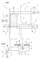
- the numeral 1 denotes a panel saw machine or cutting machine for panels 2 according to this invention.
- the panel saw machine 1 will be described in detail below solely for the parts necessary for the understanding of this invention.
- the panel saw machine 1 comprises a work table 3 for supporting the panels 2, a unit 4 for moving the panels which is movable, for moving the panels 2 on the work table 3, between a first operating position and a second operating position along a feed direction (X).
- the movement unit 4 is equipped with grippers 4a for picking up the panels 2.
- the panel saw machine 1 also comprises a rotary blade cutting unit 5, for cutting the panels 2, which is movable between a first operating position, shown by a dashed line in Figure 1 , and a second operating position along a cutting direction (Y) transversal to the feed direction (X) so as to form a cutting line 6.
- the panel saw machine 1 comprises drive means 7 for moving the cutting unit 5 and the movement unit 4 between the respective first and second operating positions.
- the cutting unit having defined a working cycle for the panel saw machine 1, makes, in use, a plurality of forward strokes in a direction V1 and return strokes in a direction V2 along the cutting line 6.
- a forward stroke is preferably defined by the passage of the cutting unit 5 from the first operating position to the second operating position whilst a return stroke is defined by the return from the second operating position to the first operating position.
- the first and the second operating positions are located at the opposite ends of the cutting line 6.
- the cutting unit 5 At the end of each forward and return stroke the cutting unit 5 is subjected to a braking phase for bringing the speed to 0 so that it is able to restart the next stroke in the opposite direction.
- the braking phases are generally controlled and managed by controlling the feeding of the units in movement, both as regards the cutting unit 5 and the unit 4 for moving the panels.
- the cutting unit 5 schematically illustrated by way of an example in Figure 2 , comprises a carriage 8 movable along the direction Y, a rotary blade 9 supported by the carriage 8, a second blade or cutter 9b not described in more detail, an electric motor M for driving the blade 9, for example by a transmission 9a.
- the panel saw machine 1, and in particular the above-mentioned drive means 7, comprise an electrical machine 10 designed, preferably and in a substantially known manner, for moving the carriage along the axis Y.
- the electrical machine 10 is of the rotary type, such as a brushless motor or a DC motor; in other example embodiments the electrical machine of the linear type 10.
- means 7 for driving the cutting unit 5 comprise a closed-loop belt 10a for pulling the carriage 8 and a transmission belt 10b operating between the electrical machine 10, of the rotary type, and the belt 10a.
- the above-mentioned drive means 7 comprise an electric drive unit 11 for moving and activating the cutting unit 5.
- the drive unit 11 comprises the electrical machine 10 and a static converter 12 for supplying the electrical machine 10.
- the static converter 12 of substantially known type, comprises a rectifier stage 13 connectable to a supply network 14 and a modulation stage 15, supplied by the rectifier stage 13 and connected at the input to the electrical machine 10 for supplying the electrical machine.
- the drive unit 11 comprises a first control stage 16, schematically represented by a corresponding block and not described further since it is of known type, which supervises the operation of the converter 12 and therefore the operation, in the specific case of the example, of the cutting unit 5.
- the static converter 12 supervises the operation of the drive unit 11 and in particular causes and makes the above-mentioned forward and reverse strokes and the braking phases which are, as mentioned above, also obtained by the drive and not by mechanical brakes.
- the above-mentioned drive means 7 comprise energy recovery means 18 for recovering the energy produced by the drive means 7 in the above-mentioned braking phases.
- the energy recovery means 18 are defined by a bank 19 of capacitors 19a.
- the capacitors 19a recover the electricity, storing it in a substantially known manner.
- the recovery means 18 store the energy recovered for subsequently returning it to the panel saw machine 1 as described in more detail below.
- the capacitors 19a are connected to the converter 12 in the intermediate stage 17.
- the converter 12 is of the two-way type, that is, it allows a flow of energy from the supply network 14 towards the load, formed in this case by the cutting unit 5, and a flow of energy from the load, that is, the cutting unit 5, to the supply network 14.
- this allows the capacitors 19a to store energy during the above-mentioned braking phases of the cutting unit 5, when the energy flows from the load to the network, and to return it, at another time, to the supply network.
- the energy stored is returned to the converter 12 when the cutting unit 5 restarts at the end of each stroke.
- the electricity network 14 forms a primary power supply source and, in the forward and return strokes of the cutting unit 5, the energy flows from the source 14, through the converter 12, to the electrical machine 10 and then to the cutting unit 5.
- the electrical machine 10 acts as a motor.
- the electrical machine 10 acts as an electricity generator, that is, it receives mechanical energy, in the form of kinetic energy, from the cutting unit 5, and transforms it into available electricity, in practice, to the terminals of the electrical machine 10.
- This available energy at the terminals of the electrical machine 10 is, at the end of the braking phases, stored in the bank of capacitors 19.
- the bank of capacitors 19 is in communication with the drive means 7 for supplying the drive means 7 with at least part of the energy recovered.
- the energy stored in the capacitors 19a is made available to the drive unit and in particular to the electrical machine 10, for the forward or return stroke, after the braking in which the energy has been stored.
- the energy contribution made available by the bank of capacitors 19 is subtracted from the energy absorbed by the supply network 14.
- the total power supplied to the drive unit 11 is given by a contribution absorbed by the supply network 14 and by a contribution due to the bank of capacitors 19.
- the panel saw machine 1 comprises a circuit 20 for pre-loading the capacitors 19a acting between the bank 19 and a power supply source.
- the pre-loading circuit 20 is directly supplied from the converter 12, as schematically illustrated in Figure 3 .
- the circuit 20 allows the capacitors to be preloaded before they are put into service for the energy recovery.
- the circuit 20 After pre-loading, the circuit 20 separates the capacitors 19a from the selected source, for example by actuating a remote control switch not illustrated.
- the means 7 for driving the panel saw machine 1 preferably comprise a braking resistor 21 supplied by the converter 12.
- the thresholds for intervention of the resistor 21 are selected as a function of the thresholds for intervention of the bank of capacitors 19.
- the resistor 21 allows any energy produced in the braking phase and not stored by the capacitors 19a to be discharged, for example in the case of a fault of the capacitors.
- the panel saw machine 1 comprises a safety system 22 for discharging the voltage if the energy stored is not reabsorbed by the electrical machine 10.
- the capacitors 19a are discharged by the safety system 22 when the machine stops when the last braking is not followed by a subsequent forward stroke which would absorb the energy stored.
- the energy stored in the capacitors 19a is dissipated by the safety system 22 if it is not reabsorbed by the converter.
- the energy recovery means 18 are operatively connected to the unit 4 for moving the panels 2.
- the drive means 7 comprise at least one second electric drive unit 111 for moving the unit 4 for moving the panels 2.
- the second electric drive unit 111 comprises a second static converter, not illustrated, similar to the converter 12 and suitably dimensioned, and at least one second electrical machine, not illustrated, which move the movement unit 4 forwards towards the cutting line 6 and backwards to a retracted position, according to substantially known work cycles and methods.
- the movement unit 4 is therefore also subject to an alternating movement where a forward stroke is followed by a return stroke and vice versa.
- the forward and return steps of the movement unit 4 are separated from each other by corresponding braking phases during which the electrical machine, as explained above with reference to the cutting unit 5, acts as an electricity generator, making a quantity of electricity available at its terminals.
- the energy recovery means 18 comprise a second bank of capacitors, not illustrated, connected to the second converter 111 in the intermediate stage of the converter for storing the energy produced in the braking phase, where the kinetic energy of the movement unit 4 actuates the second electrical machine which acts as an electricity generator, and transfers it to the same electrical machine for the following acceleration, whether it is for a forward or return stroke.
- a process for controlling the panel saw machine 1 therefore comprises the steps of supplying electricity drawn from a supply network 14 to the drive means 7 to advance the cutting unit 5 and/or the movement unit 4 for execution of a respective forward or return stroke of the cutting unit 5 and/or the movement unit 4 between the respective first and second operating positions or vice versa.
- the controlling comprises a step of braking the cutting unit 5 and/or the movement unit 4 at the end of each stroke.
- the electrical machine 10 With reference for the sake of simplicity only to the cutting unit 5, the controlling therefore comprises a step of recovering the electricity produced by the electrical machine 10 during the braking.
- the process for controlling the panel saw machine 1 comprises the work table 3 for supporting the panels 2, the unit 4 for moving the panels 2 on the work table 3, movable between the first operating position and the second operating position along the feed direction X, the cutting unit 5 movable, for cutting the panels 2, between the first operating position and the second operating position along the cutting direction Y transversal to the feed direction X, the drive means 7 for moving the cutting unit 5 between the respective first and second operating positions and for moving the movement unit 4 between the respective first and second operating positions, comprising a step of supplying electricity drawn from a supply network 14 to the drive means 7 to advance the cutting unit 5 and/or the movement unit 4 for execution of a stroke of the cutting unit 5 and/or the movement unit 4 between the respective first and second operating positions or vice versa; a step of braking the cutting unit 5 and/or the movement unit 4 at the end of the above-mentioned stroke; a step of recovering the energy produced by the drive means 7 in the braking phase.
- the energy recovered is stored in the capacitors 19a and, preferably, made available for the stroke of the relative unit following the braking.
- the controlling process therefore comprises a step of supplying the drive means 7 for the panel saw machine 1.
- the process comprises a step of supplying the cutting unit 5 with the contribution of the energy stored in the capacitors 19.
- the energy used by the drive means 7 is defined by a component absorbed by the network and by the contribution released by the capacitors 19a.
- the controlling comprises a step for implementing safety with the discharging of the accumulated energy by the safety system 20.
- the electrical machines used may be, as already indicated, of any substantially known type, rotary or linear, with or without brushes, suitably equipped with adequate systems for transmitting the motion, if necessary, to the unit moved.
- the energy produced in the braking phases, of the cutting unit and/or the movement unit, which is normally dissipated in heat, is regenerated as electricity thus allowing an improvement of the performance of the machine in acceleration.
- the braking resistors can be reduced and resized, thus implying the dispersion of a smaller quantity of heat compared to prior art solutions.
- the energy recovery implies a reduction in the so-called Carbon Footprint, that is, the emission of CO2, which is the measurement of the impact which human activities have on the environment in terms of increasing the greenhouse gases produced, measured in units of carbon dioxide.
Abstract
Description
- This invention relates to a panel saw machine for wooden panels or the like, such as, for example, slabs of plastic materials, slabs of non-ferrous metal, or slabs of cement or plasterboard.
- Panel saw machines of known type are used to cut panels of various sizes, usually placed one over the other in stacks of predetermined height.
- These panel saw machines essentially comprise a horizontal work table to support the stacks of panels to be cut; a panel movement unit or pusher, movable along a horizontal direction X, for moving the panels along the work table; and a rotary blade cutting device or unit for cutting the panel or the stack of panels movable along a cutting direction Y transversal to the direction X.
- The cutting unit comprises a carriage, movable along the direction Y, fitted with an electric motor for driving the blades.
- The panel saw machines comprise electric motors for driving the cutting unit and the movement unit for moving them forward, respectively, along the directions X and Y.
- With particular reference to the cutting unit, the respective drive comprises, for example, a brushless electric motor which is part of an electric drive unit by which the work cycles for the panel saw machine are set up.
- In general, the cutting unit performs, along the direction Y, at least one forward stroke, for cutting, and a return stroke by which it prepares for a new cutting action.
- At the end of every stroke, the cutting unit must be stopped before reversing the motion for the next stroke and the braking action is generally controlled by the electric drive unit without the intervention of mechanical bakes.
- As is known, the electric drive unit is associated with one or more braking resistors, generally in banks, because, when the electric motor for moving the cutting unit is braking, it acts like an electricity generator driven by the kinetic energy stored by the cutting unit itself, providing energy to the electric drive unit.
- After exceeding a predetermined voltage value the energy produced is absorbed by the braking resistor and converted into heat which is dissipated into the environment.
- The kinetic energy accumulated by the cutting unit in its strokes is due, mainly, to the weight of the cutting unit, determined, schematically, by the weight of the carriage, the cutting blade, the cutter (if any), the systems for moving the blades relative to the carriage and, mainly, the motor for driving the blades, that is to say, the weight of the carriage and of all the mechanical components mounted on it.
- The known panel saw machines therefore have several disadvantages.
- Under normal operating conditions a significant quantity of energy is dissipated and lost.
- The heat produced in braking is lost in the environment with consequent heating of the environment.
- The positioning of the braking resistors may be problematic due also to the current workplace regulations.
- In this context, the main purpose of this invention is to provide a panel saw machine that is free of the above mentioned disadvantages.
- One aim of this invention is to provide a panel saw machine where the energy consumption is generally reduced and the efficiency is optimised with a consequent cost saving.
- Another aim of the invention is to provide a panel saw machine which performs better than the prior art solutions in terms of acceleration and speed of the moving parts.
- The technical purpose indicated and the aims specified are substantially achieved by a panel saw machine according to
claim 1. - Further features and advantages of the invention are more apparent in the approximate and hence nonlimiting description of a preferred, non-exclusive embodiment of a panel saw machine, illustrated in the accompanying drawings in which:
-
Figure 1 is a schematic plan view from above of a panel saw machine according to this invention, partly in blocks, with some parts cut away; -
Figure 2 illustrates a detail of the panel saw machine ofFigure 1 in a schematic front view, partly in blocks, with some parts cut away in order to better illustrate others; -
Figure 3 is a diagram of an electric drive unit forming part of the panel saw machine according to this invention. - With reference to the accompanying drawings, in particular
Figure 1 , thenumeral 1 denotes a panel saw machine or cutting machine forpanels 2 according to this invention. - The
panel saw machine 1 will be described in detail below solely for the parts necessary for the understanding of this invention. - The
panel saw machine 1 comprises a work table 3 for supporting thepanels 2, aunit 4 for moving the panels which is movable, for moving thepanels 2 on the work table 3, between a first operating position and a second operating position along a feed direction (X). - In the configuration illustrated, the
movement unit 4 is equipped withgrippers 4a for picking up thepanels 2. - The
panel saw machine 1 also comprises a rotaryblade cutting unit 5, for cutting thepanels 2, which is movable between a first operating position, shown by a dashed line inFigure 1 , and a second operating position along a cutting direction (Y) transversal to the feed direction (X) so as to form a cutting line 6. - The
panel saw machine 1 comprises drive means 7 for moving thecutting unit 5 and themovement unit 4 between the respective first and second operating positions. - With particular reference to the
cutting unit 5, it should be noted that the cutting unit, having defined a working cycle for thepanel saw machine 1, makes, in use, a plurality of forward strokes in a direction V1 and return strokes in a direction V2 along the cutting line 6. - A forward stroke is preferably defined by the passage of the
cutting unit 5 from the first operating position to the second operating position whilst a return stroke is defined by the return from the second operating position to the first operating position. - Advantageously, the first and the second operating positions are located at the opposite ends of the cutting line 6.
- During the forward stroke a cutting action is performed on the
panels 2 whilst with the return stroke thecutting unit 5 is repositioned for a subsequent cutting action. - At the end of each forward and return stroke the
cutting unit 5 is subjected to a braking phase for bringing the speed to 0 so that it is able to restart the next stroke in the opposite direction. As will become clearer as this description continues, the braking phases are generally controlled and managed by controlling the feeding of the units in movement, both as regards thecutting unit 5 and theunit 4 for moving the panels. - The
cutting unit 5, schematically illustrated by way of an example inFigure 2 , comprises acarriage 8 movable along the direction Y, arotary blade 9 supported by thecarriage 8, a second blade orcutter 9b not described in more detail, an electric motor M for driving theblade 9, for example by atransmission 9a. - The
panel saw machine 1, and in particular the above-mentioned drive means 7, comprise anelectrical machine 10 designed, preferably and in a substantially known manner, for moving the carriage along the axis Y. - In one example embodiment, the
electrical machine 10 is of the rotary type, such as a brushless motor or a DC motor; in other example embodiments the electrical machine of thelinear type 10. - In the example illustrated, means 7 for driving the
cutting unit 5 comprise a closed-loop belt 10a for pulling thecarriage 8 and atransmission belt 10b operating between theelectrical machine 10, of the rotary type, and thebelt 10a. - With reference in particular to
Figure 3 , it should be noted that the above-mentioned drive means 7 comprise anelectric drive unit 11 for moving and activating thecutting unit 5. - The
drive unit 11 comprises theelectrical machine 10 and astatic converter 12 for supplying theelectrical machine 10. - Schematically, the
static converter 12, of substantially known type, comprises arectifier stage 13 connectable to asupply network 14 and amodulation stage 15, supplied by therectifier stage 13 and connected at the input to theelectrical machine 10 for supplying the electrical machine. - As is known, the
drive unit 11 comprises afirst control stage 16, schematically represented by a corresponding block and not described further since it is of known type, which supervises the operation of theconverter 12 and therefore the operation, in the specific case of the example, of thecutting unit 5. - Between the
rectifier stage 13 and themodulation stage 15 there is anintermediate DC stage 17. - The
static converter 12 supervises the operation of thedrive unit 11 and in particular causes and makes the above-mentioned forward and reverse strokes and the braking phases which are, as mentioned above, also obtained by the drive and not by mechanical brakes. - According to this invention, the above-mentioned drive means 7 comprise energy recovery means 18 for recovering the energy produced by the drive means 7 in the above-mentioned braking phases.
- In the embodiment illustrated, the energy recovery means 18 are defined by a
bank 19 ofcapacitors 19a. - The
capacitors 19a recover the electricity, storing it in a substantially known manner. - In practice, in the preferred embodiment, the recovery means 18 store the energy recovered for subsequently returning it to the
panel saw machine 1 as described in more detail below. - The
capacitors 19a are connected to theconverter 12 in theintermediate stage 17. - Advantageously, the
converter 12 is of the two-way type, that is, it allows a flow of energy from thesupply network 14 towards the load, formed in this case by thecutting unit 5, and a flow of energy from the load, that is, thecutting unit 5, to thesupply network 14. - In practice, this allows the
capacitors 19a to store energy during the above-mentioned braking phases of thecutting unit 5, when the energy flows from the load to the network, and to return it, at another time, to the supply network. - Preferably, the energy stored is returned to the
converter 12 when thecutting unit 5 restarts at the end of each stroke. - In other words, the
electricity network 14 forms a primary power supply source and, in the forward and return strokes of thecutting unit 5, the energy flows from thesource 14, through theconverter 12, to theelectrical machine 10 and then to thecutting unit 5. - In these circumstances, the
electrical machine 10 acts as a motor. - In the braking phase, the
electrical machine 10 acts as an electricity generator, that is, it receives mechanical energy, in the form of kinetic energy, from thecutting unit 5, and transforms it into available electricity, in practice, to the terminals of theelectrical machine 10. - This available energy at the terminals of the
electrical machine 10 is, at the end of the braking phases, stored in the bank ofcapacitors 19. - The bank of
capacitors 19 is in communication with the drive means 7 for supplying the drive means 7 with at least part of the energy recovered. - Advantageously, the energy stored in the
capacitors 19a is made available to the drive unit and in particular to theelectrical machine 10, for the forward or return stroke, after the braking in which the energy has been stored. - The energy contribution made available by the bank of
capacitors 19 is subtracted from the energy absorbed by thesupply network 14. - In other words, the total power supplied to the
drive unit 11 is given by a contribution absorbed by thesupply network 14 and by a contribution due to the bank ofcapacitors 19. - In this way, the absorption of energy from the
network 14 for moving thecutting unit 5 is considerably reduced with a consequent saving in and reduction of operating costs. - To optimise the storage of energy in the capacitors, the
panel saw machine 1 comprises acircuit 20 for pre-loading thecapacitors 19a acting between thebank 19 and a power supply source. - In the preferred embodiment, the
pre-loading circuit 20 is directly supplied from theconverter 12, as schematically illustrated inFigure 3 . - The
circuit 20 allows the capacitors to be preloaded before they are put into service for the energy recovery. - After pre-loading, the
circuit 20 separates thecapacitors 19a from the selected source, for example by actuating a remote control switch not illustrated. - As schematically illustrated in
Figure 3 , themeans 7 for driving the panel sawmachine 1 preferably comprise abraking resistor 21 supplied by theconverter 12. - The thresholds for intervention of the
resistor 21 are selected as a function of the thresholds for intervention of the bank ofcapacitors 19. - The
resistor 21 allows any energy produced in the braking phase and not stored by thecapacitors 19a to be discharged, for example in the case of a fault of the capacitors. - Given the high voltages which may be measured at the terminals of the bank of
capacitors 19 at the end of the braking phases, in the order of hundreds of volts for thepanel saw machines 1 of the most common size, the panel sawmachine 1 comprises a safety system 22 for discharging the voltage if the energy stored is not reabsorbed by theelectrical machine 10. - For example, the
capacitors 19a are discharged by the safety system 22 when the machine stops when the last braking is not followed by a subsequent forward stroke which would absorb the energy stored. - In practice, when the panel saw
machine 1 stops or to avoid risks for persons, the energy stored in thecapacitors 19a is dissipated by the safety system 22 if it is not reabsorbed by the converter. In an embodiment illustrated schematically inFigure 1 and also referable to the diagram ofFigure 3 , the energy recovery means 18 are operatively connected to theunit 4 for moving thepanels 2. - In more detail, the drive means 7 comprise at least one second
electric drive unit 111 for moving theunit 4 for moving thepanels 2. - The second
electric drive unit 111 comprises a second static converter, not illustrated, similar to theconverter 12 and suitably dimensioned, and at least one second electrical machine, not illustrated, which move themovement unit 4 forwards towards the cutting line 6 and backwards to a retracted position, according to substantially known work cycles and methods. - The
movement unit 4 is therefore also subject to an alternating movement where a forward stroke is followed by a return stroke and vice versa. - The forward and return steps of the
movement unit 4 are separated from each other by corresponding braking phases during which the electrical machine, as explained above with reference to thecutting unit 5, acts as an electricity generator, making a quantity of electricity available at its terminals. In this embodiment, the energy recovery means 18 comprise a second bank of capacitors, not illustrated, connected to thesecond converter 111 in the intermediate stage of the converter for storing the energy produced in the braking phase, where the kinetic energy of themovement unit 4 actuates the second electrical machine which acts as an electricity generator, and transfers it to the same electrical machine for the following acceleration, whether it is for a forward or return stroke. - In use, a process for controlling the panel saw
machine 1 therefore comprises the steps of supplying electricity drawn from asupply network 14 to the drive means 7 to advance thecutting unit 5 and/or themovement unit 4 for execution of a respective forward or return stroke of thecutting unit 5 and/or themovement unit 4 between the respective first and second operating positions or vice versa. - The controlling comprises a step of braking the
cutting unit 5 and/or themovement unit 4 at the end of each stroke. - As mentioned above, during the braking the
electrical machine 10 with reference to thecutting unit 5 or its corresponding one in theunit 4 for moving thepanels 2, acts as a generator and produces electricity available at its terminals. With reference for the sake of simplicity only to thecutting unit 5, the controlling therefore comprises a step of recovering the electricity produced by theelectrical machine 10 during the braking. - According to this invention, the process for controlling the panel saw
machine 1 comprises the work table 3 for supporting thepanels 2, theunit 4 for moving thepanels 2 on the work table 3, movable between the first operating position and the second operating position along the feed direction X, thecutting unit 5 movable, for cutting thepanels 2, between the first operating position and the second operating position along the cutting direction Y transversal to the feed direction X, the drive means 7 for moving thecutting unit 5 between the respective first and second operating positions and for moving themovement unit 4 between the respective first and second operating positions, comprising a step of supplying electricity drawn from asupply network 14 to the drive means 7 to advance thecutting unit 5 and/or themovement unit 4 for execution of a stroke of thecutting unit 5 and/or themovement unit 4 between the respective first and second operating positions or vice versa; a step of braking thecutting unit 5 and/or themovement unit 4 at the end of the above-mentioned stroke; a step of recovering the energy produced by the drive means 7 in the braking phase. - According to what has been indicated, the energy recovered is stored in the
capacitors 19a and, preferably, made available for the stroke of the relative unit following the braking. - It should be noted that the insertion, loading and unloading of the
capacitors 19a towards the actuation supply line, in particular towards theDC stage 17, occurs in a substantially known manner, as a function of the voltages at the terminals of thebank 19. - The controlling process therefore comprises a step of supplying the drive means 7 for the panel saw
machine 1. - More in detail, the process comprises a step of supplying the
cutting unit 5 with the contribution of the energy stored in thecapacitors 19. - In practice, for each stroke of the
cutting unit 5 following a braking phase the energy used by the drive means 7 is defined by a component absorbed by the network and by the contribution released by thecapacitors 19a. - As mentioned above, for the purposes of safety, if the energy stored in the
capacitors 19a is not absorbed by the drive means 7, the controlling comprises a step for implementing safety with the discharging of the accumulated energy by thesafety system 20. - It should be noted that this basic and operational layout is independent of the type of electrical machine used for moving forward the cutting unit and/or the panel movement unit.
- The electrical machines used may be, as already indicated, of any substantially known type, rotary or linear, with or without brushes, suitably equipped with adequate systems for transmitting the motion, if necessary, to the unit moved.
- The invention as described achieves significant advantages.
- The use of a system for recovering energy, the kinetic energy of the cutting unit and/or of the panel movement unit, which is then supplied to the respective drive units for the strokes immediately following the braking, allows a saving of the energy absorbed by the network.
- In the panel saw machine according to this invention, the energy produced in the braking phases, of the cutting unit and/or the movement unit, which is normally dissipated in heat, is regenerated as electricity thus allowing an improvement of the performance of the machine in acceleration.
- The braking resistors can be reduced and resized, thus implying the dispersion of a smaller quantity of heat compared to prior art solutions.
- The adoption in the panel saw machine of the bank of capacitors for the energy recovery therefore allows an energy saving, an improvement in the efficiency of the entire system as well as an environmental advantage.
- In effect, the energy recovery implies a reduction in the so-called Carbon Footprint, that is, the emission of CO2, which is the measurement of the impact which human activities have on the environment in terms of increasing the greenhouse gases produced, measured in units of carbon dioxide.
Claims (10)
- A panel saw machine for panels (2) comprising a work table (3) for supporting the panels (2), a panel (2) movement unit (4), for moving the panels (2) on the work table (3), movable between a first operating position and a second operating position along a feed direction (X), a cutting unit (5) for cutting the panels (2), movable between a first operating position and a second operating position along a cutting direction (Y) transversal to the feed direction (X), drive means (7) for moving the cutting unit (5) between the respective first and second operating positions and for moving the movement unit (4) between the respective first and second operating positions, the panel saw machine being characterised in that the drive means (7) comprise energy recovery means (18) for recovering the energy produced by the drive means (7) during a braking phase of the cutting unit (5) and/or the movement unit (4), the recovery means (18) comprising a plurality of capacitors (19a) for storing the energy produced in the braking phase.
- The machine according to claim 1, where the energy recovery means (18) are in communication with the drive means (7) for supplying the drive means (7) with at least part of the energy recovered by the recovery means (18).
- The panel saw machine according to claim 1 or 2, where the drive means (7) comprise a first electric drive unit (11) for moving the cutting unit (5), the first electric drive unit (11) comprising a first static converter (12) and a first electrical machine (10), the recovery means (18) being in communication with the first electric drive unit (11) for receiving the energy produced by the first electrical machine (10) on braking of the cutting unit (5) during which the electrical machine (10) constitutes an electricity generator.
- The panel saw machine according to any of the foregoing claims, where the drive means (7) comprise at least one braking resistor (21) for discharging the energy produced in the braking phase and not recovered.
- The panel saw machine according to any of the foregoing claims, where the recovery means (18) comprise a safety system (21) for dissipating, on stopping the panel saw machine, at least partly the energy accumulated in the braking phase.
- The panel saw machine according to any of the foregoing claims, where the drive means (7) comprise at least a second electric drive unit (111) for moving the movement unit (4), the second electric drive unit (111) comprising a second static converter and a second electrical machine, the recovery means (18) being in communication with the second electric drive unit (111) for receiving the energy produced by the second electrical machine on braking of the movement unit (4) during which the second electrical machine constitutes an electricity generator.
- A process for controlling a panel saw machine (1) comprising a work table (3) for supporting the panels (2), a unit (4) for moving the panels (2) on the work table (3), movable between a first operating position and a second operating position along a feed direction (X), a cutting unit (5) for cutting the panels (2), movable between a first operating position and a second operating position along a cutting direction (Y) transversal to the feed direction (X), drive means (7) for moving the cutting unit (5) between the respective first and second operating positions and for moving the movement unit (4) between the respective first and second operating positions, the process comprising the steps of:supplying electricity drawn from a supply network (14) to the drive means (7) to advance the cutting unit (5) and/or the movement unit (4) for execution of a stroke of the cutting unit (5) and/or the movement unit (4) between the respective first and second operating positions or vice versa;braking of the cutting unit (5) and/or the movement unit (4) at the end of the stroke;the process being characterised in that it comprises a step for recovering energy produced by the drive means (7) during the braking step, the energy produced in the braking phase being regenerated as electricity.
- A process according to claim 7, where the recovery step comprises a step for storing energy produced by the drive means (7).
- A process according to claim 8, comprising a step for supplying the drive means (7) with the stored energy.
- A process according to claim 7 or 8, comprising a step for dissipating the stored energy by means of a safety system (21).
Applications Claiming Priority (1)
| Application Number | Priority Date | Filing Date | Title |
|---|---|---|---|
| IT000274A ITBO20110274A1 (en) | 2011-05-16 | 2011-05-16 | CUTTING MACHINE |
Publications (2)
| Publication Number | Publication Date |
|---|---|
| EP2524757A1 true EP2524757A1 (en) | 2012-11-21 |
| EP2524757B1 EP2524757B1 (en) | 2014-02-12 |
Family
ID=44554724
Family Applications (1)
| Application Number | Title | Priority Date | Filing Date |
|---|---|---|---|
| EP12168188.6A Not-in-force EP2524757B1 (en) | 2011-05-16 | 2012-05-16 | A panel saw machine |
Country Status (2)
| Country | Link |
|---|---|
| EP (1) | EP2524757B1 (en) |
| IT (1) | ITBO20110274A1 (en) |
Cited By (2)
| Publication number | Priority date | Publication date | Assignee | Title |
|---|---|---|---|---|
| WO2020239275A1 (en) * | 2019-05-27 | 2020-12-03 | Siempelkamp Maschinen- Und Anlagenbau Gmbh | Device and method for assembling material panels |
| CN113510815A (en) * | 2021-03-04 | 2021-10-19 | 象乐宝(福建)新材料科技有限公司 | Clean manufacturing system of timber apron environmental protection |
Citations (6)
| Publication number | Priority date | Publication date | Assignee | Title |
|---|---|---|---|---|
| DE496358C (en) * | 1927-06-09 | 1930-04-22 | Siemens Schuckertwerke Akt Ges | Procedure for the recovery of braking energy in machines and devices with slow working stroke and fast return |
| FR915364A (en) * | 1945-05-15 | 1946-11-05 | Regenerative brake for reciprocating machine tools | |
| US5828554A (en) * | 1996-05-02 | 1998-10-27 | Chrysler Corporation | Integrated chassis, enclosure and cage |
| WO2005042215A1 (en) * | 2003-10-31 | 2005-05-12 | Giben International S.P.A. | A panel turning device |
| WO2009013583A1 (en) * | 2007-07-23 | 2009-01-29 | Giben International S.P.A. | A panel saw machine |
| EP2233236A1 (en) * | 2009-03-23 | 2010-09-29 | BIESSE S.p.A. | Method and machine for cutting wood panels or the like |
-
2011
- 2011-05-16 IT IT000274A patent/ITBO20110274A1/en unknown
-
2012
- 2012-05-16 EP EP12168188.6A patent/EP2524757B1/en not_active Not-in-force
Patent Citations (6)
| Publication number | Priority date | Publication date | Assignee | Title |
|---|---|---|---|---|
| DE496358C (en) * | 1927-06-09 | 1930-04-22 | Siemens Schuckertwerke Akt Ges | Procedure for the recovery of braking energy in machines and devices with slow working stroke and fast return |
| FR915364A (en) * | 1945-05-15 | 1946-11-05 | Regenerative brake for reciprocating machine tools | |
| US5828554A (en) * | 1996-05-02 | 1998-10-27 | Chrysler Corporation | Integrated chassis, enclosure and cage |
| WO2005042215A1 (en) * | 2003-10-31 | 2005-05-12 | Giben International S.P.A. | A panel turning device |
| WO2009013583A1 (en) * | 2007-07-23 | 2009-01-29 | Giben International S.P.A. | A panel saw machine |
| EP2233236A1 (en) * | 2009-03-23 | 2010-09-29 | BIESSE S.p.A. | Method and machine for cutting wood panels or the like |
Cited By (3)
| Publication number | Priority date | Publication date | Assignee | Title |
|---|---|---|---|---|
| WO2020239275A1 (en) * | 2019-05-27 | 2020-12-03 | Siempelkamp Maschinen- Und Anlagenbau Gmbh | Device and method for assembling material panels |
| CN113510815A (en) * | 2021-03-04 | 2021-10-19 | 象乐宝(福建)新材料科技有限公司 | Clean manufacturing system of timber apron environmental protection |
| CN113510815B (en) * | 2021-03-04 | 2023-12-22 | 象乐宝(福建)新材料科技有限公司 | Environment-friendly clean manufacturing system for wood floor |
Also Published As
| Publication number | Publication date |
|---|---|
| ITBO20110274A1 (en) | 2012-11-17 |
| EP2524757B1 (en) | 2014-02-12 |
Similar Documents
| Publication | Publication Date | Title |
|---|---|---|
| EP2639958A3 (en) | Apparatus and method for energy efficient motor drive standby operation | |
| RU2016139010A (en) | ARCHITECTURE OF THE POWER SYSTEM OF THE MULTI-MOTOR HELICOPTER AND THE RELATED HELICOPTER | |
| AU2014314196B2 (en) | Method and device for supplying auxiliary air to a rail vehicle | |
| US10780898B2 (en) | Track maintenance machine with an autonomous and redundant power supply and method for operating an energy supply system of a track maintenance machine | |
| EP2524757B1 (en) | A panel saw machine | |
| JP2014147226A (en) | Motor controller including power storage device and resistance discharge device | |
| JP2009023817A (en) | Crane device | |
| EP0938255A3 (en) | Electric-component supplying method and apparatus | |
| CN201238046Y (en) | Inlet/outlet apparatus | |
| CN201322541Y (en) | Automatic charging machine | |
| CN107949535A (en) | the crane driver of motor operation | |
| CN104014901B (en) | Multistation automatic welding machine for circular seam and its welding method | |
| CN108819719A (en) | A kind of charging method and device of motor controller of new energy automobile | |
| CN203485257U (en) | Full-automatic plate trimming machine | |
| CN206011306U (en) | A kind of sawing sheet saws feeder | |
| CN203806816U (en) | Automatic cloth collecting machine for cut dust-free cloth sheets | |
| CN103662946A (en) | Novel rewinder | |
| CN102335918A (en) | Automatic feeding and blanking manipulator | |
| WO2008031608A1 (en) | Method and apparatus for minimizing the electrical energy drawn by an industrial installation | |
| CN105817772A (en) | Rotary dual-workbench cantilever type laser cutting machine | |
| CN104400773B (en) | Sheet frame storing unit and working method thereof | |
| CN101666334B (en) | Press traverse table pump station pressure supplementing device and pressure supplementing method thereof | |
| CN217578074U (en) | Protection device of crane | |
| CN101116885A (en) | Fin high-speed punch press aluminum foil storing device and storing method thereof | |
| CN109571787A (en) | Degumming separation method after tooling transmitting device, degumming machine system and silicon rod cutting |
Legal Events
| Date | Code | Title | Description |
|---|---|---|---|
| PUAI | Public reference made under article 153(3) epc to a published international application that has entered the european phase |
Free format text: ORIGINAL CODE: 0009012 |
|
| AK | Designated contracting states |
Kind code of ref document: A1 Designated state(s): AL AT BE BG CH CY CZ DE DK EE ES FI FR GB GR HR HU IE IS IT LI LT LU LV MC MK MT NL NO PL PT RO RS SE SI SK SM TR |
|
| AX | Request for extension of the european patent |
Extension state: BA ME |
|
| RAP1 | Party data changed (applicant data changed or rights of an application transferred) |
Owner name: GIBEN INTERNATIONAL S.P.A. Owner name: POLITECNICO DI MILANO |
|
| RIN1 | Information on inventor provided before grant (corrected) |
Inventor name: MAPELLI, FERDINANDO LUIGI Inventor name: BENUZZI, PIERGIORGIO Inventor name: TARSITANO, DAVIDE |
|
| 17P | Request for examination filed |
Effective date: 20130806 |
|
| RBV | Designated contracting states (corrected) |
Designated state(s): AL AT BE BG CH CY CZ DE DK EE ES FI FR GB GR HR HU IE IS IT LI LT LU LV MC MK MT NL NO PL PT RO RS SE SI SK SM TR |
|
| RIN1 | Information on inventor provided before grant (corrected) |
Inventor name: BENUZZI, PIERGIORGIO Inventor name: TARSITANO, DAVIDE Inventor name: MAPELLI, FERDINANDO LUIGI |
|
| GRAP | Despatch of communication of intention to grant a patent |
Free format text: ORIGINAL CODE: EPIDOSNIGR1 |
|
| RIC1 | Information provided on ipc code assigned before grant |
Ipc: B23Q 5/04 20060101ALI20130920BHEP Ipc: B23D 47/00 20060101AFI20130920BHEP Ipc: B27B 5/065 20060101ALI20130920BHEP Ipc: B23Q 5/10 20060101ALI20130920BHEP |
|
| INTG | Intention to grant announced |
Effective date: 20131010 |
|
| GRAS | Grant fee paid |
Free format text: ORIGINAL CODE: EPIDOSNIGR3 |
|
| GRAA | (expected) grant |
Free format text: ORIGINAL CODE: 0009210 |
|
| AK | Designated contracting states |
Kind code of ref document: B1 Designated state(s): AL AT BE BG CH CY CZ DE DK EE ES FI FR GB GR HR HU IE IS IT LI LT LU LV MC MK MT NL NO PL PT RO RS SE SI SK SM TR |
|
| REG | Reference to a national code |
Ref country code: GB Ref legal event code: FG4D |
|
| REG | Reference to a national code |
Ref country code: CH Ref legal event code: EP |
|
| REG | Reference to a national code |
Ref country code: AT Ref legal event code: REF Ref document number: 651910 Country of ref document: AT Kind code of ref document: T Effective date: 20140215 |
|
| REG | Reference to a national code |
Ref country code: IE Ref legal event code: FG4D |
|
| REG | Reference to a national code |
Ref country code: DE Ref legal event code: R096 Ref document number: 602012000893 Country of ref document: DE Effective date: 20140327 |
|
| REG | Reference to a national code |
Ref country code: NL Ref legal event code: VDEP Effective date: 20140212 |
|
| REG | Reference to a national code |
Ref country code: LT Ref legal event code: MG4D |
|
| PG25 | Lapsed in a contracting state [announced via postgrant information from national office to epo] |
Ref country code: IS Free format text: LAPSE BECAUSE OF FAILURE TO SUBMIT A TRANSLATION OF THE DESCRIPTION OR TO PAY THE FEE WITHIN THE PRESCRIBED TIME-LIMIT Effective date: 20140612 Ref country code: NO Free format text: LAPSE BECAUSE OF FAILURE TO SUBMIT A TRANSLATION OF THE DESCRIPTION OR TO PAY THE FEE WITHIN THE PRESCRIBED TIME-LIMIT Effective date: 20140512 Ref country code: LT Free format text: LAPSE BECAUSE OF FAILURE TO SUBMIT A TRANSLATION OF THE DESCRIPTION OR TO PAY THE FEE WITHIN THE PRESCRIBED TIME-LIMIT Effective date: 20140212 |
|
| PG25 | Lapsed in a contracting state [announced via postgrant information from national office to epo] |
Ref country code: FI Free format text: LAPSE BECAUSE OF FAILURE TO SUBMIT A TRANSLATION OF THE DESCRIPTION OR TO PAY THE FEE WITHIN THE PRESCRIBED TIME-LIMIT Effective date: 20140212 Ref country code: ES Free format text: LAPSE BECAUSE OF FAILURE TO SUBMIT A TRANSLATION OF THE DESCRIPTION OR TO PAY THE FEE WITHIN THE PRESCRIBED TIME-LIMIT Effective date: 20140212 Ref country code: SE Free format text: LAPSE BECAUSE OF FAILURE TO SUBMIT A TRANSLATION OF THE DESCRIPTION OR TO PAY THE FEE WITHIN THE PRESCRIBED TIME-LIMIT Effective date: 20140212 Ref country code: PT Free format text: LAPSE BECAUSE OF FAILURE TO SUBMIT A TRANSLATION OF THE DESCRIPTION OR TO PAY THE FEE WITHIN THE PRESCRIBED TIME-LIMIT Effective date: 20140612 Ref country code: NL Free format text: LAPSE BECAUSE OF FAILURE TO SUBMIT A TRANSLATION OF THE DESCRIPTION OR TO PAY THE FEE WITHIN THE PRESCRIBED TIME-LIMIT Effective date: 20140212 Ref country code: CY Free format text: LAPSE BECAUSE OF FAILURE TO SUBMIT A TRANSLATION OF THE DESCRIPTION OR TO PAY THE FEE WITHIN THE PRESCRIBED TIME-LIMIT Effective date: 20140212 |
|
| PG25 | Lapsed in a contracting state [announced via postgrant information from national office to epo] |
Ref country code: BE Free format text: LAPSE BECAUSE OF FAILURE TO SUBMIT A TRANSLATION OF THE DESCRIPTION OR TO PAY THE FEE WITHIN THE PRESCRIBED TIME-LIMIT Effective date: 20140212 Ref country code: LV Free format text: LAPSE BECAUSE OF FAILURE TO SUBMIT A TRANSLATION OF THE DESCRIPTION OR TO PAY THE FEE WITHIN THE PRESCRIBED TIME-LIMIT Effective date: 20140212 Ref country code: RS Free format text: LAPSE BECAUSE OF FAILURE TO SUBMIT A TRANSLATION OF THE DESCRIPTION OR TO PAY THE FEE WITHIN THE PRESCRIBED TIME-LIMIT Effective date: 20140212 Ref country code: HR Free format text: LAPSE BECAUSE OF FAILURE TO SUBMIT A TRANSLATION OF THE DESCRIPTION OR TO PAY THE FEE WITHIN THE PRESCRIBED TIME-LIMIT Effective date: 20140212 |
|
| PG25 | Lapsed in a contracting state [announced via postgrant information from national office to epo] |
Ref country code: EE Free format text: LAPSE BECAUSE OF FAILURE TO SUBMIT A TRANSLATION OF THE DESCRIPTION OR TO PAY THE FEE WITHIN THE PRESCRIBED TIME-LIMIT Effective date: 20140212 Ref country code: DK Free format text: LAPSE BECAUSE OF FAILURE TO SUBMIT A TRANSLATION OF THE DESCRIPTION OR TO PAY THE FEE WITHIN THE PRESCRIBED TIME-LIMIT Effective date: 20140212 Ref country code: RO Free format text: LAPSE BECAUSE OF FAILURE TO SUBMIT A TRANSLATION OF THE DESCRIPTION OR TO PAY THE FEE WITHIN THE PRESCRIBED TIME-LIMIT Effective date: 20140212 Ref country code: CZ Free format text: LAPSE BECAUSE OF FAILURE TO SUBMIT A TRANSLATION OF THE DESCRIPTION OR TO PAY THE FEE WITHIN THE PRESCRIBED TIME-LIMIT Effective date: 20140212 |
|
| REG | Reference to a national code |
Ref country code: DE Ref legal event code: R097 Ref document number: 602012000893 Country of ref document: DE |
|
| PG25 | Lapsed in a contracting state [announced via postgrant information from national office to epo] |
Ref country code: PL Free format text: LAPSE BECAUSE OF FAILURE TO SUBMIT A TRANSLATION OF THE DESCRIPTION OR TO PAY THE FEE WITHIN THE PRESCRIBED TIME-LIMIT Effective date: 20140212 Ref country code: SK Free format text: LAPSE BECAUSE OF FAILURE TO SUBMIT A TRANSLATION OF THE DESCRIPTION OR TO PAY THE FEE WITHIN THE PRESCRIBED TIME-LIMIT Effective date: 20140212 |
|
| PLBE | No opposition filed within time limit |
Free format text: ORIGINAL CODE: 0009261 |
|
| STAA | Information on the status of an ep patent application or granted ep patent |
Free format text: STATUS: NO OPPOSITION FILED WITHIN TIME LIMIT |
|
| PG25 | Lapsed in a contracting state [announced via postgrant information from national office to epo] |
Ref country code: LU Free format text: LAPSE BECAUSE OF FAILURE TO SUBMIT A TRANSLATION OF THE DESCRIPTION OR TO PAY THE FEE WITHIN THE PRESCRIBED TIME-LIMIT Effective date: 20140516 |
|
| 26N | No opposition filed |
Effective date: 20141113 |
|
| PG25 | Lapsed in a contracting state [announced via postgrant information from national office to epo] |
Ref country code: MC Free format text: LAPSE BECAUSE OF FAILURE TO SUBMIT A TRANSLATION OF THE DESCRIPTION OR TO PAY THE FEE WITHIN THE PRESCRIBED TIME-LIMIT Effective date: 20140212 |
|
| REG | Reference to a national code |
Ref country code: IE Ref legal event code: MM4A |
|
| REG | Reference to a national code |
Ref country code: DE Ref legal event code: R097 Ref document number: 602012000893 Country of ref document: DE Effective date: 20141113 |
|
| REG | Reference to a national code |
Ref country code: FR Ref legal event code: ST Effective date: 20150130 |
|
| PG25 | Lapsed in a contracting state [announced via postgrant information from national office to epo] |
Ref country code: IE Free format text: LAPSE BECAUSE OF NON-PAYMENT OF DUE FEES Effective date: 20140516 |
|
| PG25 | Lapsed in a contracting state [announced via postgrant information from national office to epo] |
Ref country code: FR Free format text: LAPSE BECAUSE OF NON-PAYMENT OF DUE FEES Effective date: 20140602 Ref country code: SI Free format text: LAPSE BECAUSE OF FAILURE TO SUBMIT A TRANSLATION OF THE DESCRIPTION OR TO PAY THE FEE WITHIN THE PRESCRIBED TIME-LIMIT Effective date: 20140212 |
|
| REG | Reference to a national code |
Ref country code: CH Ref legal event code: PL |
|
| PG25 | Lapsed in a contracting state [announced via postgrant information from national office to epo] |
Ref country code: CH Free format text: LAPSE BECAUSE OF NON-PAYMENT OF DUE FEES Effective date: 20150531 Ref country code: LI Free format text: LAPSE BECAUSE OF NON-PAYMENT OF DUE FEES Effective date: 20150531 |
|
| PG25 | Lapsed in a contracting state [announced via postgrant information from national office to epo] |
Ref country code: MT Free format text: LAPSE BECAUSE OF FAILURE TO SUBMIT A TRANSLATION OF THE DESCRIPTION OR TO PAY THE FEE WITHIN THE PRESCRIBED TIME-LIMIT Effective date: 20140212 |
|
| PG25 | Lapsed in a contracting state [announced via postgrant information from national office to epo] |
Ref country code: SM Free format text: LAPSE BECAUSE OF FAILURE TO SUBMIT A TRANSLATION OF THE DESCRIPTION OR TO PAY THE FEE WITHIN THE PRESCRIBED TIME-LIMIT Effective date: 20140212 |
|
| PG25 | Lapsed in a contracting state [announced via postgrant information from national office to epo] |
Ref country code: GR Free format text: LAPSE BECAUSE OF FAILURE TO SUBMIT A TRANSLATION OF THE DESCRIPTION OR TO PAY THE FEE WITHIN THE PRESCRIBED TIME-LIMIT Effective date: 20140513 Ref country code: BG Free format text: LAPSE BECAUSE OF FAILURE TO SUBMIT A TRANSLATION OF THE DESCRIPTION OR TO PAY THE FEE WITHIN THE PRESCRIBED TIME-LIMIT Effective date: 20140212 |
|
| PG25 | Lapsed in a contracting state [announced via postgrant information from national office to epo] |
Ref country code: TR Free format text: LAPSE BECAUSE OF FAILURE TO SUBMIT A TRANSLATION OF THE DESCRIPTION OR TO PAY THE FEE WITHIN THE PRESCRIBED TIME-LIMIT Effective date: 20140212 Ref country code: HU Free format text: LAPSE BECAUSE OF FAILURE TO SUBMIT A TRANSLATION OF THE DESCRIPTION OR TO PAY THE FEE WITHIN THE PRESCRIBED TIME-LIMIT; INVALID AB INITIO Effective date: 20120516 |
|
| GBPC | Gb: european patent ceased through non-payment of renewal fee |
Effective date: 20160516 |
|
| PG25 | Lapsed in a contracting state [announced via postgrant information from national office to epo] |
Ref country code: GB Free format text: LAPSE BECAUSE OF NON-PAYMENT OF DUE FEES Effective date: 20160516 |
|
| REG | Reference to a national code |
Ref country code: DE Ref legal event code: R082 Ref document number: 602012000893 Country of ref document: DE Representative=s name: FARAGO PATENTANWALTSGESELLSCHAFT MBH, DE Ref country code: DE Ref legal event code: R082 Ref document number: 602012000893 Country of ref document: DE Representative=s name: FARAGO PATENTANWAELTE, DE Ref country code: DE Ref legal event code: R082 Ref document number: 602012000893 Country of ref document: DE Representative=s name: SCHIEBER FARAGO PATENTANWAELTE, DE Ref country code: DE Ref legal event code: R082 Ref document number: 602012000893 Country of ref document: DE Representative=s name: FARAGO PATENTANWALTS- UND RECHTSANWALTSGESELLS, DE |
|
| REG | Reference to a national code |
Ref country code: DE Ref legal event code: R082 Ref document number: 602012000893 Country of ref document: DE Representative=s name: FARAGO PATENTANWALTSGESELLSCHAFT MBH, DE Ref country code: DE Ref legal event code: R082 Ref document number: 602012000893 Country of ref document: DE Representative=s name: SCHIEBER FARAGO PATENTANWAELTE, DE Ref country code: DE Ref legal event code: R082 Ref document number: 602012000893 Country of ref document: DE Representative=s name: FARAGO PATENTANWALTS- UND RECHTSANWALTSGESELLS, DE Ref country code: DE Ref legal event code: R082 Ref document number: 602012000893 Country of ref document: DE Representative=s name: FARAGO PATENTANWAELTE, DE |
|
| REG | Reference to a national code |
Ref country code: DE Ref legal event code: R082 Ref document number: 602012000893 Country of ref document: DE Representative=s name: SCHIEBER - FARAGO PATENTANWAELTE, DE Ref country code: DE Ref legal event code: R082 Ref document number: 602012000893 Country of ref document: DE Representative=s name: FARAGO PATENTANWALTSGESELLSCHAFT MBH, DE Ref country code: DE Ref legal event code: R082 Ref document number: 602012000893 Country of ref document: DE Representative=s name: FARAGO PATENTANWALTS- UND RECHTSANWALTSGESELLS, DE Ref country code: DE Ref legal event code: R082 Ref document number: 602012000893 Country of ref document: DE Representative=s name: FARAGO PATENTANWAELTE, DE |
|
| PG25 | Lapsed in a contracting state [announced via postgrant information from national office to epo] |
Ref country code: MK Free format text: LAPSE BECAUSE OF FAILURE TO SUBMIT A TRANSLATION OF THE DESCRIPTION OR TO PAY THE FEE WITHIN THE PRESCRIBED TIME-LIMIT Effective date: 20140212 |
|
| PG25 | Lapsed in a contracting state [announced via postgrant information from national office to epo] |
Ref country code: AL Free format text: LAPSE BECAUSE OF FAILURE TO SUBMIT A TRANSLATION OF THE DESCRIPTION OR TO PAY THE FEE WITHIN THE PRESCRIBED TIME-LIMIT Effective date: 20140212 |
|
| PGFP | Annual fee paid to national office [announced via postgrant information from national office to epo] |
Ref country code: AT Payment date: 20191202 Year of fee payment: 8 |
|
| REG | Reference to a national code |
Ref country code: AT Ref legal event code: MM01 Ref document number: 651910 Country of ref document: AT Kind code of ref document: T Effective date: 20200516 |
|
| PG25 | Lapsed in a contracting state [announced via postgrant information from national office to epo] |
Ref country code: AT Free format text: LAPSE BECAUSE OF NON-PAYMENT OF DUE FEES Effective date: 20200516 |
|
| PGFP | Annual fee paid to national office [announced via postgrant information from national office to epo] |
Ref country code: DE Payment date: 20210505 Year of fee payment: 10 Ref country code: IT Payment date: 20210511 Year of fee payment: 10 |
|
| REG | Reference to a national code |
Ref country code: DE Ref legal event code: R082 Ref document number: 602012000893 Country of ref document: DE Representative=s name: SCHIEBER - FARAGO PATENTANWAELTE, DE Ref country code: DE Ref legal event code: R082 Ref document number: 602012000893 Country of ref document: DE Representative=s name: FARAGO PATENTANWALTSGESELLSCHAFT MBH, DE |
|
| REG | Reference to a national code |
Ref country code: DE Ref legal event code: R082 Ref document number: 602012000893 Country of ref document: DE Representative=s name: SCHIEBER - FARAGO PATENTANWAELTE, DE |
|
| REG | Reference to a national code |
Ref country code: DE Ref legal event code: R119 Ref document number: 602012000893 Country of ref document: DE |
|
| PG25 | Lapsed in a contracting state [announced via postgrant information from national office to epo] |
Ref country code: DE Free format text: LAPSE BECAUSE OF NON-PAYMENT OF DUE FEES Effective date: 20221201 |
|
| PG25 | Lapsed in a contracting state [announced via postgrant information from national office to epo] |
Ref country code: IT Free format text: LAPSE BECAUSE OF NON-PAYMENT OF DUE FEES Effective date: 20220516 |