EP2524262B1 - Cell counting slide with lateral reservoir for promoting uniform cell distribution - Google Patents
Cell counting slide with lateral reservoir for promoting uniform cell distribution Download PDFInfo
- Publication number
- EP2524262B1 EP2524262B1 EP11733236.1A EP11733236A EP2524262B1 EP 2524262 B1 EP2524262 B1 EP 2524262B1 EP 11733236 A EP11733236 A EP 11733236A EP 2524262 B1 EP2524262 B1 EP 2524262B1
- Authority
- EP
- European Patent Office
- Prior art keywords
- reservoir
- cell counting
- slide
- counting section
- cell
- Prior art date
- Legal status (The legal status is an assumption and is not a legal conclusion. Google has not performed a legal analysis and makes no representation as to the accuracy of the status listed.)
- Active
Links
Images
Classifications
-
- G—PHYSICS
- G02—OPTICS
- G02B—OPTICAL ELEMENTS, SYSTEMS OR APPARATUS
- G02B21/00—Microscopes
- G02B21/34—Microscope slides, e.g. mounting specimens on microscope slides
-
- Y—GENERAL TAGGING OF NEW TECHNOLOGICAL DEVELOPMENTS; GENERAL TAGGING OF CROSS-SECTIONAL TECHNOLOGIES SPANNING OVER SEVERAL SECTIONS OF THE IPC; TECHNICAL SUBJECTS COVERED BY FORMER USPC CROSS-REFERENCE ART COLLECTIONS [XRACs] AND DIGESTS
- Y10—TECHNICAL SUBJECTS COVERED BY FORMER USPC
- Y10S—TECHNICAL SUBJECTS COVERED BY FORMER USPC CROSS-REFERENCE ART COLLECTIONS [XRACs] AND DIGESTS
- Y10S435/00—Chemistry: molecular biology and microbiology
- Y10S435/97—Test strip or test slide
-
- Y—GENERAL TAGGING OF NEW TECHNOLOGICAL DEVELOPMENTS; GENERAL TAGGING OF CROSS-SECTIONAL TECHNOLOGIES SPANNING OVER SEVERAL SECTIONS OF THE IPC; TECHNICAL SUBJECTS COVERED BY FORMER USPC CROSS-REFERENCE ART COLLECTIONS [XRACs] AND DIGESTS
- Y10—TECHNICAL SUBJECTS COVERED BY FORMER USPC
- Y10T—TECHNICAL SUBJECTS COVERED BY FORMER US CLASSIFICATION
- Y10T436/00—Chemistry: analytical and immunological testing
- Y10T436/11—Automated chemical analysis
- Y10T436/112499—Automated chemical analysis with sample on test slide
Definitions
- This invention resides in the field of laboratory apparatus for biological and biochemical laboratories, and particularly to apparatus for cell counting.
- Cell counting in suspensions of blood cells, bacteria, and biological cells in general is a procedure commonly used in clinical and research laboratories. Measurement of the number of cells per unit volume of the suspension by cell counting is valuable in assessing such qualities as biological function and activity as well as cell viability and growth.
- Cell counting is commonly performed on a hemocytometer, which utilizes a microscope slide to hold the suspension and a microscopic viewer to allow viewer observation of the slide for manual counting, either directly or from an image of the slide.
- a drop of the suspension is placed in the slide and covered by a second slide or any thin transparent cover slip.
- the gap also referred to as the "chamber” between the slide and the cover slip is typically on the order of 100 ⁇ m (microns).
- a grid on the underside of the cover slip delineates an area for counting, and knowledge of both the area and the depth of the gap allows the viewer to determine the cell count per unit volume.
- the grid enables the viewer to select a portion of the grid whose area is small relative to the dimensions of the slide, thereby enabling the user to count cells with relative ease and quickness and with minimal risk of error.
- a critical feature of the slide and cover slip combination is therefore the distance between them, and another is the evenness of the distribution of the cells across the width of the slide. If the distance is not uniform or the cells are not distributed evenly, the concentration calculated from the selected area can differ from the concentration in the suspension as a whole.
- the present invention resides in a cell counting slide that contains a counting chamber and one or more reservoirs along the periphery of the counting chamber.
- the counting chamber is also referred to herein as a cell counting section, and it and the reservoir(s) together form a cavity in the interior of the cell counting slide.
- the slide in many cases is a combination of two plates, one forming the base and the other taking the place of the cover slip in conventional cell counting slides.
- the two plates can be individual components that are stacked together for use, or they can be fused together for sale, shipment, or use as a unit. Alternatively, they can be formed (cast or machined) as a single (unitary) piece of material.
- the depth (or height) of the cell counting section which defines the depth of the cell suspension during counting, is set by the floor and ceiling of the section, which are two opposing and parallel flat surfaces.
- the upper plate is transparent to allow counting from above, and in many embodiments, the entire slide is transparent.
- the cell counting slide further comprises a dam within said reservoir arranged to slow down flow of a cell suspension from said reservoir to said cell counting section.
- the reservoir preferably extends the full length of a side of the chamber.
- the chamber is rectangular in shape and the reservoir extends the full length of one of the shorter (lateral) sides of the rectangle, and in many of these cases, two reservoirs are included, one on each of two opposing sides of the rectangle. In either case, the reservoir extends below the floor of the cell counting section and is deeper than the gap between the floor and ceiling of the cell counting section, preferably by a factor of at least two.
- the suspension can be fed to the reservoir through a port in the upper plate of the slide, such as by a pipette. When a suspension is added in this manner, the reservoir fills with the suspension before the suspension enters the counting chamber. Only after the reservoir is filled does the suspension enter the cell counting section, and when the reservoir extends the full length of one side the passage of the cells into the cell counting section occurs substantially evenly along the length of that side.
- the depths of both the counting chamber and the reservoir(s) can vary. For a cell counting section that is 100 ⁇ m (microns) in depth, for example, best results in most cases will be obtained with a reservoir that is 300 ⁇ m (microns) to 1 mm (1,000 microns), or most preferably about 500 ⁇ m (microns), in depth.
- the reservoir does not require a uniform depth.
- reservoirs extending the lengths of each of two opposing sides of the rectangle are useful, allowing the user a choice between the two reservoirs.
- the suspension can be added through a single reservoir, using the opposing reservoir as a vent for air to escape from the cell counting section.
- Each slide is constructed as two plates, a top plate and a bottom plate.
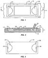
- the cell counting slide of the art is depicted in a top view of the stacked plates in FIG. 1 , a vertical cross section of the stacked plates in FIG. 2 taken along the line 2-2 of FIG. 1 , and a top view of the top plate in FIG. 3 .
- the bottom plate 12 serves as the floor of the cell counting section and the floors of the reservoirs
- the top plate 13 serves as the ceiling of the cell counting section.
- Cell counting is performed by taking an image of the cells in the cell counting section by direct visual observation through the top plate.
- the top plate 13 is transparent, and in preferred embodiments, both top and bottom plates 12, 13 are transparent.
- the bottom plate 12 is a plate with two parallel recessed rectangular sections 14, 15 separated by a platform 16 that forms the floor of the cell counting section.
- the height of the platform 16 is less than that of the periphery 17 of the plate surrounding the two recessed rectangular sections 14, 15 and the platform.
- the top plate 13 extends over and rests on the periphery 17 of the bottom plate, leaving a gap 18 between the platform 16 and the central portion of the upper part 13.
- the recessed rectangular sections 14, 15 thus form the reservoirs, and the gap 18 forms the cell counting section, the reservoirs and the cell counting section together constituting the cavity of the slide.
- FIG. 3 is a flat plate that is continuous except for two openings 21, 22 ( FIG. 1 ) that are generally U-shaped with outer edges 23, 24 aligned with the outer edges of the two reservoirs 14, 15 in the lower plate 12. These openings thus serve as ports for loading the slide.
- the cell suspension is applied by pipette 25 through one of the ports 22 to the underlying reservoir 15 to first fill the reservoir. Once the reservoir is filled, further suspension is supplied through the pipette and suspension from the reservoir flows over into the cell counting section 18.
- the platform 16 can be at the same height as the periphery 17 of the bottom plate 12, while the central section of the top plate 13 above the platform can be thinner than the remainder of the top plate, thereby forming a gap of the same width as in the structure shown in FIGS. 1, 2, and 3 .
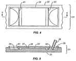
- the slide of the invention is shown in a top view in FIG. 4 , and in a vertical cross section in FIG. 5 taken along the line 5-5 of FIG. 4 .
- the slide 31 is shown in two parts -- a bottom plate 32 which serves as the floors of both the chamber (i.e., the cell counting section) and the reservoirs, and a top plate 33 which serves as the ceiling of the chamber and through which counting is performed.
- the slide 31 of FIGS. 4 and 5 contains two reservoirs 34, 35 with a platform 36 between them and a gap 37 between the platform 36 and the top plate 33 to serve as the chamber for cell counting.
- a pipette 38 is shown for use in the same manner as the pipette of FIG. 2 .
- the added feature in the embodiment of FIGS. 4 and 5 is a pair of dams 41, 42, one dam within each of the reservoirs 34, 35 along and parallel to the side of the reservoir closest to the platform, and extending the length of the reservoir.
- the dams 41, 42 serve to slow down the flow of the suspension toward the platform and improve the distribution of the suspension along the edges of the platform before passing over the edges into the cell counting section of the slide cavity.
- the dam thus produces a more even distribution of the cells in the cell counting area.
- a single reservoir can contain two or more dams, for example extending parallel to the edge of the platform 36.
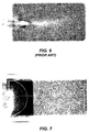
- FIG. 6 representing the prior art (lacking the reservoirs and the dams) and 7 representing the present invention (containing both the reservoirs and the dams).
- FIG. 6 representing the prior art (lacking the reservoirs and the dams)
- 7 representing the present invention (containing both the reservoirs and the dams).
- the images show that the cell slide of the prior art ( FIG. 6 ) has a lower concentration of cells at the center of the chamber, which thus appears lighter in contrast, while the cell slide of the invention ( FIG. 7 ) has an even distribution of cells across the length and width of the slide.
Landscapes
- Physics & Mathematics (AREA)
- Chemical & Material Sciences (AREA)
- Analytical Chemistry (AREA)
- General Physics & Mathematics (AREA)
- Optics & Photonics (AREA)
- Sampling And Sample Adjustment (AREA)
- Investigating Or Analysing Biological Materials (AREA)
- Microscoopes, Condenser (AREA)
- Apparatus Associated With Microorganisms And Enzymes (AREA)
Description
- This invention resides in the field of laboratory apparatus for biological and biochemical laboratories, and particularly to apparatus for cell counting.
- Cell counting in suspensions of blood cells, bacteria, and biological cells in general is a procedure commonly used in clinical and research laboratories. Measurement of the number of cells per unit volume of the suspension by cell counting is valuable in assessing such qualities as biological function and activity as well as cell viability and growth. Cell counting is commonly performed on a hemocytometer, which utilizes a microscope slide to hold the suspension and a microscopic viewer to allow viewer observation of the slide for manual counting, either directly or from an image of the slide. To count cells in a suspension, a drop of the suspension is placed in the slide and covered by a second slide or any thin transparent cover slip. The gap (also referred to as the "chamber") between the slide and the cover slip is typically on the order of 100 µm (microns). A grid on the underside of the cover slip delineates an area for counting, and knowledge of both the area and the depth of the gap allows the viewer to determine the cell count per unit volume. The grid enables the viewer to select a portion of the grid whose area is small relative to the dimensions of the slide, thereby enabling the user to count cells with relative ease and quickness and with minimal risk of error. A critical feature of the slide and cover slip combination is therefore the distance between them, and another is the evenness of the distribution of the cells across the width of the slide. If the distance is not uniform or the cells are not distributed evenly, the concentration calculated from the selected area can differ from the concentration in the suspension as a whole.
- Conventional means of placing the suspension in the chamber of a cell counting slide involve the use of a pipette to introduce the suspension to one side of the chamber through a notch or similar opening in the cover sheet. The suspension then flows from the notch into the chamber. Examples of disclosures of slides of this type and their use are found in
US Patent Nos. 4,171,866 and5,349,436 . Another convectional means of that type further comprises a reservoir at one side of the chamber and the suspension is introduced in the reservoir through an opening in the coversheet. Examples of disclosures of slides of this type and their use are found inGB-A-2127577 US 2004/180397 andJP H09 236756 - The present invention resides in a cell counting slide that contains a counting chamber and one or more reservoirs along the periphery of the counting chamber. The counting chamber is also referred to herein as a cell counting section, and it and the reservoir(s) together form a cavity in the interior of the cell counting slide. The slide in many cases is a combination of two plates, one forming the base and the other taking the place of the cover slip in conventional cell counting slides. The two plates can be individual components that are stacked together for use, or they can be fused together for sale, shipment, or use as a unit. Alternatively, they can be formed (cast or machined) as a single (unitary) piece of material. In all cases, the depth (or height) of the cell counting section, which defines the depth of the cell suspension during counting, is set by the floor and ceiling of the section, which are two opposing and parallel flat surfaces. The upper plate is transparent to allow counting from above, and in many embodiments, the entire slide is transparent. The cell counting slide further comprises a dam within said reservoir arranged to slow down flow of a cell suspension from said reservoir to said cell counting section.
- The reservoir preferably extends the full length of a side of the chamber. In many cases, the chamber is rectangular in shape and the reservoir extends the full length of one of the shorter (lateral) sides of the rectangle, and in many of these cases, two reservoirs are included, one on each of two opposing sides of the rectangle. In either case, the reservoir extends below the floor of the cell counting section and is deeper than the gap between the floor and ceiling of the cell counting section, preferably by a factor of at least two. The suspension can be fed to the reservoir through a port in the upper plate of the slide, such as by a pipette. When a suspension is added in this manner, the reservoir fills with the suspension before the suspension enters the counting chamber. Only after the reservoir is filled does the suspension enter the cell counting section, and when the reservoir extends the full length of one side the passage of the cells into the cell counting section occurs substantially evenly along the length of that side.
- The depths of both the counting chamber and the reservoir(s) can vary. For a cell counting section that is 100 µm (microns) in depth, for example, best results in most cases will be obtained with a reservoir that is 300 µm (microns) to 1 mm (1,000 microns), or most preferably about 500 µm (microns), in depth. The reservoir does not require a uniform depth. For a rectangular counting area, reservoirs extending the lengths of each of two opposing sides of the rectangle are useful, allowing the user a choice between the two reservoirs. The suspension can be added through a single reservoir, using the opposing reservoir as a vent for air to escape from the cell counting section.
-
-
FIG. 1 is a top view of a cell counting slide of the prior art. -
FIG. 2 is a cross section of the embodiment ofFIG. 1 , taken along the line 2-2 ofFIG. 1 . -
FIG. 3 is a copy view of the upper part of the embodiment ofFIG. 1 . -
FIG. 4 is a top view of a cell counting slide of the present invention. -
FIG. 5 is a cross section of the embodiment ofFIG. 4 , taken along the line 5-5 ofFIG. 4 . -
FIG. 6 is an image of cells in a cell counting slide of the prior art. -
FIG. 7 is an image of cells in a cell counting slide of the present invention. - The drawings attached further illustrate the invention. Each slide is constructed as two plates, a top plate and a bottom plate.
- The cell counting slide of the art is depicted in a top view of the stacked plates in
FIG. 1 , a vertical cross section of the stacked plates inFIG. 2 taken along the line 2-2 ofFIG. 1 , and a top view of the top plate inFIG. 3 . Of thestacked plates 11, thebottom plate 12 serves as the floor of the cell counting section and the floors of the reservoirs, and thetop plate 13 serves as the ceiling of the cell counting section. Cell counting is performed by taking an image of the cells in the cell counting section by direct visual observation through the top plate. As mentioned above, thetop plate 13 is transparent, and in preferred embodiments, both top andbottom plates - As seen in the cross section of
FIG. 2 , thebottom plate 12 is a plate with two parallel recessedrectangular sections periphery 17 of the plate surrounding the two recessedrectangular sections top plate 13 extends over and rests on theperiphery 17 of the bottom plate, leaving agap 18 between the platform 16 and the central portion of theupper part 13. The recessedrectangular sections gap 18 forms the cell counting section, the reservoirs and the cell counting section together constituting the cavity of the slide. Thetop plate 13, shown separately in a top view inFIG. 3 , is a flat plate that is continuous except for twoopenings 21, 22 (FIG. 1 ) that are generally U-shaped withouter edges reservoirs lower plate 12. These openings thus serve as ports for loading the slide. In use, the cell suspension is applied bypipette 25 through one of theports 22 to theunderlying reservoir 15 to first fill the reservoir. Once the reservoir is filled, further suspension is supplied through the pipette and suspension from the reservoir flows over into thecell counting section 18. - In an alternative structure, the platform 16 can be at the same height as the
periphery 17 of thebottom plate 12, while the central section of thetop plate 13 above the platform can be thinner than the remainder of the top plate, thereby forming a gap of the same width as in the structure shown inFIGS. 1, 2, and 3 . - The slide of the invention is shown in a top view in
FIG. 4 , and in a vertical cross section inFIG. 5 taken along the line 5-5 ofFIG. 4 . Here again, theslide 31 is shown in two parts -- abottom plate 32 which serves as the floors of both the chamber (i.e., the cell counting section) and the reservoirs, and atop plate 33 which serves as the ceiling of the chamber and through which counting is performed. Like the slide ofFIGS. 1, 2, and 3 , theslide 31 ofFIGS. 4 and 5 contains tworeservoirs platform 36 between them and agap 37 between theplatform 36 and thetop plate 33 to serve as the chamber for cell counting. Apipette 38 is shown for use in the same manner as the pipette ofFIG. 2 . The added feature in the embodiment ofFIGS. 4 and 5 is a pair ofdams reservoirs dams platform 36. - A comparison of cell distributions in slides of the present invention vs. those of the prior art is seen in
FIG. 6 representing the prior art (lacking the reservoirs and the dams) and 7 representing the present invention (containing both the reservoirs and the dams). The images show that the cell slide of the prior art (FIG. 6 ) has a lower concentration of cells at the center of the chamber, which thus appears lighter in contrast, while the cell slide of the invention (FIG. 7 ) has an even distribution of cells across the length and width of the slide. - In the claims appended hereto, the term "a" or "an" is intended to mean "one or more." The term "comprise" and variations thereof such as "comprises" and "comprising," when preceding the recitation of a step or an element, are intended to mean that the addition of further steps or elements is optional and not excluded.
Claims (12)
- A cell counting slide (31) comprising:a substantially flat enclosure with a cavity therein, said cavity comprising:a cell counting section bounded by a planar floor (36) and a transparent planar ceiling (33) parallel to said floor (36) and separated from said floor (36) by a gap (37) that accommodates a cell suspension and is sufficiently shallow to permit individual observation of all cells therein through said ceiling (33);a reservoir (34, 35) extending the length of an edge of said cell counting section and having a depth substantially exceeding said gap (37), said reservoir extending below said planar floor (36) and open to said cell counting section along said entire length; anda port (21, 22) in said ceiling (33) opening into said reservoir (34, 35),
characterized in thatthe cell counting slide (31) further comprises a dam (41, 42) within said reservoir (34, 35) arranged to slow down flow of a cell suspension from said reservoir to said cell counting section. - The cell counting slide (31) of claim 1 wherein said cavity comprises first and second said reservoirs (34, 35) extending along the lengths of opposing edges of said cell counting section, and first and second said ports (21, 22), one said port (21, 22) opening into each said reservoir (34, 35).
- The cell counting slide (31) of claim 1 wherein said gap (37) has a height and said reservoir (34, 35) has a depth at least twice said height.
- The cell counting slide (31) of claim 1 wherein said cell counting section is rectangular with two longitudinal edges and two lateral edges each shorter than said longitudinal edges, and said reservoir (34, 35) extends the length of one of said lateral edges.
- The cell counting slide (31) of claim 2 wherein said cell counting section is rectangular with two longitudinal edges and two lateral edges each shorter than said longitudinal edges, with one said reservoir extending the length of each of said lateral edges.
- The cell counting slide (31) of claim 1 wherein said enclosure consists of upper and lower plates (33, 32), said upper plate (33) forming said ceiling (33) and said lower plate (32) forming said floor (36) and said reservoir (34, 35) when said plates (33, 32) are stacked.
- The cell counting slide of claim 1 wherein said reservoir (34, 35) has a floor and said dam (41, 42) is a ridge in said reservoir floor parallel to and adjacent to said edge of said cell counting section.
- The cell counting slide of claim 2 further comprising a first dam (41) within said first reservoir (34) and a second dam (42) within said second reservoir (35), each said dam (41, 42) arranged parallel to and adjacent to one of said opposing edges of said cell counting section.
- A method for counting cells in a cell suspension, said method comprising:(a) placing said suspension in a cell counting slide (31) comprising:a substantially flat enclosure with a cavity therein, said cavity comprising:a cell counting section bounded by a planar floor (36) and a transparent planar ceiling (33) parallel to said floor (36) and separated from said floor (36) by a gap (37) that accommodates a cell suspension and is sufficiently shallow to permit individual observation of all cells therein through said ceiling (33);a reservoir (34, 35) extending the length of an edge of said cell counting section and having a depth substantially exceeding said gap (37), said reservoir extending below said planar floor (36) and open to said cell counting section along said entire length; anda port (21, 22) in said ceiling (33) opening into said reservoir (34, 35),by feeding said suspension to said reservoir (34, 35) through said port (21, 22) to fill said reservoir (34, 35) and to cause said suspension to overflow from said reservoir (34, 35) into said cell counting section; and(b) examining said cell counting section through said transparent planar ceiling (33) to count cells in at least a portion of said cell counting section,characterized in that
said cell counting slide (31) further comprises a dam (41, 42) within said reservoir (34, 35), and step (a) further comprises causing said suspension to flow over said dam (41, 42) to enter said cell counting section. - The method of claim 9 wherein:said cavity comprises first and second said reservoirs (34, 35) extending along the lengths of opposing edges of said cell counting section, and said dam (41) is within said first reservoir (34);said cell counting slide (31) comprises first and second said ports (21, 22), one said port (21, 22) opening into each said reservoir (34, 35); andstep (a) comprises feeding said suspension to said first reservoir (34) through said first port (21) while venting air from said cavity through said second port (22).
- The method of claim 9 wherein said cell counting section is rectangular with two longitudinal edges and two lateral edges each shorter than said longitudinal edges, and said reservoir (34, 35) extends the length of one of said lateral edges.
- The method of claim 10 wherein said cell counting section is rectangular with two longitudinal edges and two lateral edges each shorter than said longitudinal edges, said first reservoir (34) extends the length of one of said lateral edges, and second reservoir (35) extends the length of the other of said lateral edges.
Applications Claiming Priority (3)
| Application Number | Priority Date | Filing Date | Title |
|---|---|---|---|
| US29437310P | 2010-01-12 | 2010-01-12 | |
| US12/986,696 US8852524B2 (en) | 2010-01-12 | 2011-01-07 | Cell counting slide with lateral reservoir for promoting uniform cell distribution |
| PCT/US2011/020685 WO2011087988A1 (en) | 2010-01-12 | 2011-01-10 | Cell counting slide with lateral reservoir for promoting uniform cell distribution |
Publications (3)
| Publication Number | Publication Date |
|---|---|
| EP2524262A1 EP2524262A1 (en) | 2012-11-21 |
| EP2524262A4 EP2524262A4 (en) | 2013-11-27 |
| EP2524262B1 true EP2524262B1 (en) | 2016-04-06 |
Family
ID=44304596
Family Applications (1)
| Application Number | Title | Priority Date | Filing Date |
|---|---|---|---|
| EP11733236.1A Active EP2524262B1 (en) | 2010-01-12 | 2011-01-10 | Cell counting slide with lateral reservoir for promoting uniform cell distribution |
Country Status (5)
| Country | Link |
|---|---|
| US (1) | US8852524B2 (en) |
| EP (1) | EP2524262B1 (en) |
| JP (1) | JP5559361B2 (en) |
| CA (1) | CA2786432C (en) |
| WO (1) | WO2011087988A1 (en) |
Families Citing this family (10)
| Publication number | Priority date | Publication date | Assignee | Title |
|---|---|---|---|---|
| US9001200B2 (en) | 2010-01-12 | 2015-04-07 | Bio-Rad Laboratories, Inc. | Cell characterization using multiple focus planes |
| US10114020B2 (en) | 2010-10-11 | 2018-10-30 | Mbio Diagnostics, Inc. | System and device for analyzing a fluidic sample |
| US9354155B2 (en) | 2011-05-31 | 2016-05-31 | Bio-Rad Laboratories, Inc. | Cell counting systems and methods |
| WO2014070235A1 (en) | 2012-10-29 | 2014-05-08 | Mbio Diagnostics, Inc. | Biological particle identification system, cartridge and associated methods |
| DK2914251T3 (en) | 2012-11-05 | 2019-11-04 | Us Health | Ketone bodies to protect tissue from damage due to ionization radiation |
| KR101582412B1 (en) * | 2014-05-19 | 2016-01-06 | 인제대학교 산학협력단 | Biopsy stand |
| CN107805596A (en) * | 2016-09-09 | 2018-03-16 | 东北农业大学 | A kind of direct counting box of bacterium for simple glass slide |
| US10052754B1 (en) * | 2017-04-12 | 2018-08-21 | Ullman Devices Corporation | Magnetic tool holder |
| ES2863800T3 (en) * | 2017-12-22 | 2021-10-11 | Minitueb Gmbh | Procedure and devices for analyzing sperm samples |
| CN114561274A (en) * | 2021-07-15 | 2022-05-31 | 上海萌薇生物医疗科技有限公司 | Cell metering plate synthesized by ultrasonic welding process and use method thereof |
Family Cites Families (16)
| Publication number | Priority date | Publication date | Assignee | Title |
|---|---|---|---|---|
| US4171866A (en) | 1978-04-20 | 1979-10-23 | Tolles Walter E | Disposable volumetric slide |
| US4466289A (en) | 1982-03-17 | 1984-08-21 | Lam Calvin K | Capacitance manometer with digital output |
| GB2127577B (en) * | 1982-09-20 | 1985-12-11 | V Tech Inc | Wet-mount microscopic examination slide |
| JPS63105715A (en) | 1986-10-24 | 1988-05-11 | 松下電器産業株式会社 | Vacuum electric heat-insulating pot |
| JPH0227111U (en) * | 1988-08-09 | 1990-02-22 | ||
| US5349436A (en) | 1992-12-02 | 1994-09-20 | Harry Fisch | Biological assembly |
| US5306467A (en) | 1993-02-17 | 1994-04-26 | Hamilton-Thorn Research | Apparatus for measurement of cell concentration in a biological sample employing a magnetic slide loading apparatus |
| JPH09236756A (en) | 1996-02-29 | 1997-09-09 | Fukae Kasei Kk | Plastic slide for optical microscope |
| US6165739A (en) | 1996-03-13 | 2000-12-26 | Compucyte Corporation | Multiple simultaneous testing media |
| TW587694U (en) * | 2003-03-14 | 2004-05-11 | Mau-Guei Jang | Protruded platform type quantitative cell counter plate |
| US7718124B2 (en) * | 2005-06-02 | 2010-05-18 | Minitube Of America, Inc. | Counting, viability assessment, analysis and manipulation chamber |
| US8711474B2 (en) | 2009-06-26 | 2014-04-29 | Bio-Rad Laboratories, Inc. | Modular microscope construction |
| US8570370B2 (en) | 2009-08-31 | 2013-10-29 | Bio-Rad Laboratories, Inc. | Compact automated cell counter |
| US9001200B2 (en) | 2010-01-12 | 2015-04-07 | Bio-Rad Laboratories, Inc. | Cell characterization using multiple focus planes |
| US8609363B2 (en) | 2010-11-18 | 2013-12-17 | Bio-Rad Laboratories, Inc. | Viability cell counting by differential light absorption |
| US9354155B2 (en) | 2011-05-31 | 2016-05-31 | Bio-Rad Laboratories, Inc. | Cell counting systems and methods |
-
2011
- 2011-01-07 US US12/986,696 patent/US8852524B2/en active Active
- 2011-01-10 JP JP2012548990A patent/JP5559361B2/en not_active Expired - Fee Related
- 2011-01-10 EP EP11733236.1A patent/EP2524262B1/en active Active
- 2011-01-10 CA CA2786432A patent/CA2786432C/en active Active
- 2011-01-10 WO PCT/US2011/020685 patent/WO2011087988A1/en not_active Ceased
Also Published As
| Publication number | Publication date |
|---|---|
| US20120015392A1 (en) | 2012-01-19 |
| CA2786432C (en) | 2016-03-22 |
| EP2524262A4 (en) | 2013-11-27 |
| WO2011087988A1 (en) | 2011-07-21 |
| CA2786432A1 (en) | 2011-07-21 |
| JP2013517529A (en) | 2013-05-16 |
| EP2524262A1 (en) | 2012-11-21 |
| US8852524B2 (en) | 2014-10-07 |
| JP5559361B2 (en) | 2014-07-23 |
Similar Documents
| Publication | Publication Date | Title |
|---|---|---|
| EP2524262B1 (en) | Cell counting slide with lateral reservoir for promoting uniform cell distribution | |
| EP0800571B1 (en) | Biological analysis device having improved contamination prevention | |
| EP1949310B1 (en) | Method for performing counts within a biologic fluid sample | |
| EP3148700B1 (en) | Single column microplate system and carrier for analysis of biological samples | |
| JP3907624B2 (en) | Access hole for feeding multi-well filter plates | |
| US6819408B1 (en) | Method for obtaining a monolayer of desired particles in a liquid sample | |
| US7820451B2 (en) | Analytical test element | |
| EP0210071B1 (en) | Microscope inspection slide | |
| JP2009512859A5 (en) | ||
| US20060099570A1 (en) | Device and method for non-invasive measurement of the individual metabolic rate of a substantially spherical metabolizing particle | |
| EP2270573B1 (en) | Cover for a counting, viability assessment, analysis and manipulation chamber | |
| JP4077950B2 (en) | Container with lid | |
| USRE33826E (en) | Microscope inspection slide | |
| US7005008B2 (en) | Reaction vessel | |
| US20250019636A1 (en) | Device for separating motile cells | |
| CN215986705U (en) | Glass slide | |
| EP3919172A1 (en) | Microfluidic device | |
| JP2026027734A (en) | Auxiliary member and observation method | |
| US20020093735A1 (en) | Slide for the microscopic examination of biological fluids | |
| US20230003748A1 (en) | Device for Testing Blood Plasma | |
| US20250257301A1 (en) | Microfluidic apparatus | |
| JP2024541272A (en) | Well plate apparatus and method for filling same | |
| CN113946045A (en) | Glass slide and use method thereof |
Legal Events
| Date | Code | Title | Description |
|---|---|---|---|
| PUAI | Public reference made under article 153(3) epc to a published international application that has entered the european phase |
Free format text: ORIGINAL CODE: 0009012 |
|
| 17P | Request for examination filed |
Effective date: 20120705 |
|
| AK | Designated contracting states |
Kind code of ref document: A1 Designated state(s): AL AT BE BG CH CY CZ DE DK EE ES FI FR GB GR HR HU IE IS IT LI LT LU LV MC MK MT NL NO PL PT RO RS SE SI SK SM TR |
|
| DAX | Request for extension of the european patent (deleted) | ||
| A4 | Supplementary search report drawn up and despatched |
Effective date: 20131025 |
|
| RIC1 | Information provided on ipc code assigned before grant |
Ipc: G02B 21/34 20060101AFI20131021BHEP |
|
| GRAP | Despatch of communication of intention to grant a patent |
Free format text: ORIGINAL CODE: EPIDOSNIGR1 |
|
| INTG | Intention to grant announced |
Effective date: 20151009 |
|
| GRAS | Grant fee paid |
Free format text: ORIGINAL CODE: EPIDOSNIGR3 |
|
| GRAA | (expected) grant |
Free format text: ORIGINAL CODE: 0009210 |
|
| AK | Designated contracting states |
Kind code of ref document: B1 Designated state(s): AL AT BE BG CH CY CZ DE DK EE ES FI FR GB GR HR HU IE IS IT LI LT LU LV MC MK MT NL NO PL PT RO RS SE SI SK SM TR |
|
| REG | Reference to a national code |
Ref country code: GB Ref legal event code: FG4D |
|
| REG | Reference to a national code |
Ref country code: AT Ref legal event code: REF Ref document number: 788403 Country of ref document: AT Kind code of ref document: T Effective date: 20160415 Ref country code: CH Ref legal event code: EP |
|
| REG | Reference to a national code |
Ref country code: IE Ref legal event code: FG4D |
|
| REG | Reference to a national code |
Ref country code: DE Ref legal event code: R096 Ref document number: 602011024928 Country of ref document: DE |
|
| REG | Reference to a national code |
Ref country code: LT Ref legal event code: MG4D Ref country code: NL Ref legal event code: MP Effective date: 20160406 |
|
| REG | Reference to a national code |
Ref country code: AT Ref legal event code: MK05 Ref document number: 788403 Country of ref document: AT Kind code of ref document: T Effective date: 20160406 |
|
| PG25 | Lapsed in a contracting state [announced via postgrant information from national office to epo] |
Ref country code: NL Free format text: LAPSE BECAUSE OF FAILURE TO SUBMIT A TRANSLATION OF THE DESCRIPTION OR TO PAY THE FEE WITHIN THE PRESCRIBED TIME-LIMIT Effective date: 20160406 |
|
| PG25 | Lapsed in a contracting state [announced via postgrant information from national office to epo] |
Ref country code: IS Free format text: LAPSE BECAUSE OF FAILURE TO SUBMIT A TRANSLATION OF THE DESCRIPTION OR TO PAY THE FEE WITHIN THE PRESCRIBED TIME-LIMIT Effective date: 20160806 Ref country code: NO Free format text: LAPSE BECAUSE OF FAILURE TO SUBMIT A TRANSLATION OF THE DESCRIPTION OR TO PAY THE FEE WITHIN THE PRESCRIBED TIME-LIMIT Effective date: 20160706 Ref country code: LT Free format text: LAPSE BECAUSE OF FAILURE TO SUBMIT A TRANSLATION OF THE DESCRIPTION OR TO PAY THE FEE WITHIN THE PRESCRIBED TIME-LIMIT Effective date: 20160406 Ref country code: FI Free format text: LAPSE BECAUSE OF FAILURE TO SUBMIT A TRANSLATION OF THE DESCRIPTION OR TO PAY THE FEE WITHIN THE PRESCRIBED TIME-LIMIT Effective date: 20160406 Ref country code: PL Free format text: LAPSE BECAUSE OF FAILURE TO SUBMIT A TRANSLATION OF THE DESCRIPTION OR TO PAY THE FEE WITHIN THE PRESCRIBED TIME-LIMIT Effective date: 20160406 |
|
| PG25 | Lapsed in a contracting state [announced via postgrant information from national office to epo] |
Ref country code: PT Free format text: LAPSE BECAUSE OF FAILURE TO SUBMIT A TRANSLATION OF THE DESCRIPTION OR TO PAY THE FEE WITHIN THE PRESCRIBED TIME-LIMIT Effective date: 20160808 Ref country code: SE Free format text: LAPSE BECAUSE OF FAILURE TO SUBMIT A TRANSLATION OF THE DESCRIPTION OR TO PAY THE FEE WITHIN THE PRESCRIBED TIME-LIMIT Effective date: 20160406 Ref country code: LV Free format text: LAPSE BECAUSE OF FAILURE TO SUBMIT A TRANSLATION OF THE DESCRIPTION OR TO PAY THE FEE WITHIN THE PRESCRIBED TIME-LIMIT Effective date: 20160406 Ref country code: AT Free format text: LAPSE BECAUSE OF FAILURE TO SUBMIT A TRANSLATION OF THE DESCRIPTION OR TO PAY THE FEE WITHIN THE PRESCRIBED TIME-LIMIT Effective date: 20160406 Ref country code: RS Free format text: LAPSE BECAUSE OF FAILURE TO SUBMIT A TRANSLATION OF THE DESCRIPTION OR TO PAY THE FEE WITHIN THE PRESCRIBED TIME-LIMIT Effective date: 20160406 Ref country code: ES Free format text: LAPSE BECAUSE OF FAILURE TO SUBMIT A TRANSLATION OF THE DESCRIPTION OR TO PAY THE FEE WITHIN THE PRESCRIBED TIME-LIMIT Effective date: 20160406 Ref country code: GR Free format text: LAPSE BECAUSE OF FAILURE TO SUBMIT A TRANSLATION OF THE DESCRIPTION OR TO PAY THE FEE WITHIN THE PRESCRIBED TIME-LIMIT Effective date: 20160707 Ref country code: HR Free format text: LAPSE BECAUSE OF FAILURE TO SUBMIT A TRANSLATION OF THE DESCRIPTION OR TO PAY THE FEE WITHIN THE PRESCRIBED TIME-LIMIT Effective date: 20160406 |
|
| PG25 | Lapsed in a contracting state [announced via postgrant information from national office to epo] |
Ref country code: IT Free format text: LAPSE BECAUSE OF FAILURE TO SUBMIT A TRANSLATION OF THE DESCRIPTION OR TO PAY THE FEE WITHIN THE PRESCRIBED TIME-LIMIT Effective date: 20160406 Ref country code: BE Free format text: LAPSE BECAUSE OF FAILURE TO SUBMIT A TRANSLATION OF THE DESCRIPTION OR TO PAY THE FEE WITHIN THE PRESCRIBED TIME-LIMIT Effective date: 20160406 |
|
| REG | Reference to a national code |
Ref country code: DE Ref legal event code: R097 Ref document number: 602011024928 Country of ref document: DE |
|
| REG | Reference to a national code |
Ref country code: FR Ref legal event code: PLFP Year of fee payment: 7 |
|
| PG25 | Lapsed in a contracting state [announced via postgrant information from national office to epo] |
Ref country code: EE Free format text: LAPSE BECAUSE OF FAILURE TO SUBMIT A TRANSLATION OF THE DESCRIPTION OR TO PAY THE FEE WITHIN THE PRESCRIBED TIME-LIMIT Effective date: 20160406 Ref country code: DK Free format text: LAPSE BECAUSE OF FAILURE TO SUBMIT A TRANSLATION OF THE DESCRIPTION OR TO PAY THE FEE WITHIN THE PRESCRIBED TIME-LIMIT Effective date: 20160406 Ref country code: CZ Free format text: LAPSE BECAUSE OF FAILURE TO SUBMIT A TRANSLATION OF THE DESCRIPTION OR TO PAY THE FEE WITHIN THE PRESCRIBED TIME-LIMIT Effective date: 20160406 Ref country code: RO Free format text: LAPSE BECAUSE OF FAILURE TO SUBMIT A TRANSLATION OF THE DESCRIPTION OR TO PAY THE FEE WITHIN THE PRESCRIBED TIME-LIMIT Effective date: 20160406 Ref country code: SK Free format text: LAPSE BECAUSE OF FAILURE TO SUBMIT A TRANSLATION OF THE DESCRIPTION OR TO PAY THE FEE WITHIN THE PRESCRIBED TIME-LIMIT Effective date: 20160406 |
|
| PLBE | No opposition filed within time limit |
Free format text: ORIGINAL CODE: 0009261 |
|
| STAA | Information on the status of an ep patent application or granted ep patent |
Free format text: STATUS: NO OPPOSITION FILED WITHIN TIME LIMIT |
|
| PG25 | Lapsed in a contracting state [announced via postgrant information from national office to epo] |
Ref country code: SM Free format text: LAPSE BECAUSE OF FAILURE TO SUBMIT A TRANSLATION OF THE DESCRIPTION OR TO PAY THE FEE WITHIN THE PRESCRIBED TIME-LIMIT Effective date: 20160406 |
|
| 26N | No opposition filed |
Effective date: 20170110 |
|
| PG25 | Lapsed in a contracting state [announced via postgrant information from national office to epo] |
Ref country code: SI Free format text: LAPSE BECAUSE OF FAILURE TO SUBMIT A TRANSLATION OF THE DESCRIPTION OR TO PAY THE FEE WITHIN THE PRESCRIBED TIME-LIMIT Effective date: 20160406 |
|
| REG | Reference to a national code |
Ref country code: CH Ref legal event code: PL |
|
| PG25 | Lapsed in a contracting state [announced via postgrant information from national office to epo] |
Ref country code: MC Free format text: LAPSE BECAUSE OF FAILURE TO SUBMIT A TRANSLATION OF THE DESCRIPTION OR TO PAY THE FEE WITHIN THE PRESCRIBED TIME-LIMIT Effective date: 20160406 |
|
| PG25 | Lapsed in a contracting state [announced via postgrant information from national office to epo] |
Ref country code: LI Free format text: LAPSE BECAUSE OF NON-PAYMENT OF DUE FEES Effective date: 20170131 Ref country code: CH Free format text: LAPSE BECAUSE OF NON-PAYMENT OF DUE FEES Effective date: 20170131 |
|
| REG | Reference to a national code |
Ref country code: IE Ref legal event code: MM4A |
|
| PG25 | Lapsed in a contracting state [announced via postgrant information from national office to epo] |
Ref country code: LU Free format text: LAPSE BECAUSE OF NON-PAYMENT OF DUE FEES Effective date: 20170110 |
|
| REG | Reference to a national code |
Ref country code: FR Ref legal event code: PLFP Year of fee payment: 8 |
|
| PG25 | Lapsed in a contracting state [announced via postgrant information from national office to epo] |
Ref country code: IE Free format text: LAPSE BECAUSE OF NON-PAYMENT OF DUE FEES Effective date: 20170110 |
|
| PG25 | Lapsed in a contracting state [announced via postgrant information from national office to epo] |
Ref country code: MT Free format text: LAPSE BECAUSE OF NON-PAYMENT OF DUE FEES Effective date: 20170110 |
|
| PG25 | Lapsed in a contracting state [announced via postgrant information from national office to epo] |
Ref country code: AL Free format text: LAPSE BECAUSE OF FAILURE TO SUBMIT A TRANSLATION OF THE DESCRIPTION OR TO PAY THE FEE WITHIN THE PRESCRIBED TIME-LIMIT Effective date: 20160406 |
|
| PG25 | Lapsed in a contracting state [announced via postgrant information from national office to epo] |
Ref country code: HU Free format text: LAPSE BECAUSE OF FAILURE TO SUBMIT A TRANSLATION OF THE DESCRIPTION OR TO PAY THE FEE WITHIN THE PRESCRIBED TIME-LIMIT; INVALID AB INITIO Effective date: 20110110 |
|
| PG25 | Lapsed in a contracting state [announced via postgrant information from national office to epo] |
Ref country code: BG Free format text: LAPSE BECAUSE OF FAILURE TO SUBMIT A TRANSLATION OF THE DESCRIPTION OR TO PAY THE FEE WITHIN THE PRESCRIBED TIME-LIMIT Effective date: 20160406 |
|
| PG25 | Lapsed in a contracting state [announced via postgrant information from national office to epo] |
Ref country code: CY Free format text: LAPSE BECAUSE OF NON-PAYMENT OF DUE FEES Effective date: 20160406 |
|
| PG25 | Lapsed in a contracting state [announced via postgrant information from national office to epo] |
Ref country code: MK Free format text: LAPSE BECAUSE OF FAILURE TO SUBMIT A TRANSLATION OF THE DESCRIPTION OR TO PAY THE FEE WITHIN THE PRESCRIBED TIME-LIMIT Effective date: 20160406 |
|
| PG25 | Lapsed in a contracting state [announced via postgrant information from national office to epo] |
Ref country code: TR Free format text: LAPSE BECAUSE OF FAILURE TO SUBMIT A TRANSLATION OF THE DESCRIPTION OR TO PAY THE FEE WITHIN THE PRESCRIBED TIME-LIMIT Effective date: 20160406 |
|
| P01 | Opt-out of the competence of the unified patent court (upc) registered |
Effective date: 20230510 |
|
| PGFP | Annual fee paid to national office [announced via postgrant information from national office to epo] |
Ref country code: GB Payment date: 20260126 Year of fee payment: 16 |
|
| PGFP | Annual fee paid to national office [announced via postgrant information from national office to epo] |
Ref country code: DE Payment date: 20260127 Year of fee payment: 16 |
|
| PGFP | Annual fee paid to national office [announced via postgrant information from national office to epo] |
Ref country code: FR Payment date: 20260127 Year of fee payment: 16 |