EP2524262B1 - Zellzählungsschieber mit seitlicher kammer zur förderung einer gleichförmigen zellverteilung - Google Patents
Zellzählungsschieber mit seitlicher kammer zur förderung einer gleichförmigen zellverteilung Download PDFInfo
- Publication number
- EP2524262B1 EP2524262B1 EP11733236.1A EP11733236A EP2524262B1 EP 2524262 B1 EP2524262 B1 EP 2524262B1 EP 11733236 A EP11733236 A EP 11733236A EP 2524262 B1 EP2524262 B1 EP 2524262B1
- Authority
- EP
- European Patent Office
- Prior art keywords
- reservoir
- cell counting
- slide
- counting section
- cell
- Prior art date
- Legal status (The legal status is an assumption and is not a legal conclusion. Google has not performed a legal analysis and makes no representation as to the accuracy of the status listed.)
- Active
Links
Images
Classifications
-
- G—PHYSICS
- G02—OPTICS
- G02B—OPTICAL ELEMENTS, SYSTEMS OR APPARATUS
- G02B21/00—Microscopes
- G02B21/34—Microscope slides, e.g. mounting specimens on microscope slides
-
- Y—GENERAL TAGGING OF NEW TECHNOLOGICAL DEVELOPMENTS; GENERAL TAGGING OF CROSS-SECTIONAL TECHNOLOGIES SPANNING OVER SEVERAL SECTIONS OF THE IPC; TECHNICAL SUBJECTS COVERED BY FORMER USPC CROSS-REFERENCE ART COLLECTIONS [XRACs] AND DIGESTS
- Y10—TECHNICAL SUBJECTS COVERED BY FORMER USPC
- Y10S—TECHNICAL SUBJECTS COVERED BY FORMER USPC CROSS-REFERENCE ART COLLECTIONS [XRACs] AND DIGESTS
- Y10S435/00—Chemistry: molecular biology and microbiology
- Y10S435/97—Test strip or test slide
-
- Y—GENERAL TAGGING OF NEW TECHNOLOGICAL DEVELOPMENTS; GENERAL TAGGING OF CROSS-SECTIONAL TECHNOLOGIES SPANNING OVER SEVERAL SECTIONS OF THE IPC; TECHNICAL SUBJECTS COVERED BY FORMER USPC CROSS-REFERENCE ART COLLECTIONS [XRACs] AND DIGESTS
- Y10—TECHNICAL SUBJECTS COVERED BY FORMER USPC
- Y10T—TECHNICAL SUBJECTS COVERED BY FORMER US CLASSIFICATION
- Y10T436/00—Chemistry: analytical and immunological testing
- Y10T436/11—Automated chemical analysis
- Y10T436/112499—Automated chemical analysis with sample on test slide
Definitions
- This invention resides in the field of laboratory apparatus for biological and biochemical laboratories, and particularly to apparatus for cell counting.
- Cell counting in suspensions of blood cells, bacteria, and biological cells in general is a procedure commonly used in clinical and research laboratories. Measurement of the number of cells per unit volume of the suspension by cell counting is valuable in assessing such qualities as biological function and activity as well as cell viability and growth.
- Cell counting is commonly performed on a hemocytometer, which utilizes a microscope slide to hold the suspension and a microscopic viewer to allow viewer observation of the slide for manual counting, either directly or from an image of the slide.
- a drop of the suspension is placed in the slide and covered by a second slide or any thin transparent cover slip.
- the gap also referred to as the "chamber” between the slide and the cover slip is typically on the order of 100 ⁇ m (microns).
- a grid on the underside of the cover slip delineates an area for counting, and knowledge of both the area and the depth of the gap allows the viewer to determine the cell count per unit volume.
- the grid enables the viewer to select a portion of the grid whose area is small relative to the dimensions of the slide, thereby enabling the user to count cells with relative ease and quickness and with minimal risk of error.
- a critical feature of the slide and cover slip combination is therefore the distance between them, and another is the evenness of the distribution of the cells across the width of the slide. If the distance is not uniform or the cells are not distributed evenly, the concentration calculated from the selected area can differ from the concentration in the suspension as a whole.
- the present invention resides in a cell counting slide that contains a counting chamber and one or more reservoirs along the periphery of the counting chamber.
- the counting chamber is also referred to herein as a cell counting section, and it and the reservoir(s) together form a cavity in the interior of the cell counting slide.
- the slide in many cases is a combination of two plates, one forming the base and the other taking the place of the cover slip in conventional cell counting slides.
- the two plates can be individual components that are stacked together for use, or they can be fused together for sale, shipment, or use as a unit. Alternatively, they can be formed (cast or machined) as a single (unitary) piece of material.
- the depth (or height) of the cell counting section which defines the depth of the cell suspension during counting, is set by the floor and ceiling of the section, which are two opposing and parallel flat surfaces.
- the upper plate is transparent to allow counting from above, and in many embodiments, the entire slide is transparent.
- the cell counting slide further comprises a dam within said reservoir arranged to slow down flow of a cell suspension from said reservoir to said cell counting section.
- the reservoir preferably extends the full length of a side of the chamber.
- the chamber is rectangular in shape and the reservoir extends the full length of one of the shorter (lateral) sides of the rectangle, and in many of these cases, two reservoirs are included, one on each of two opposing sides of the rectangle. In either case, the reservoir extends below the floor of the cell counting section and is deeper than the gap between the floor and ceiling of the cell counting section, preferably by a factor of at least two.
- the suspension can be fed to the reservoir through a port in the upper plate of the slide, such as by a pipette. When a suspension is added in this manner, the reservoir fills with the suspension before the suspension enters the counting chamber. Only after the reservoir is filled does the suspension enter the cell counting section, and when the reservoir extends the full length of one side the passage of the cells into the cell counting section occurs substantially evenly along the length of that side.
- the depths of both the counting chamber and the reservoir(s) can vary. For a cell counting section that is 100 ⁇ m (microns) in depth, for example, best results in most cases will be obtained with a reservoir that is 300 ⁇ m (microns) to 1 mm (1,000 microns), or most preferably about 500 ⁇ m (microns), in depth.
- the reservoir does not require a uniform depth.
- reservoirs extending the lengths of each of two opposing sides of the rectangle are useful, allowing the user a choice between the two reservoirs.
- the suspension can be added through a single reservoir, using the opposing reservoir as a vent for air to escape from the cell counting section.
- Each slide is constructed as two plates, a top plate and a bottom plate.
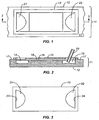
- the cell counting slide of the art is depicted in a top view of the stacked plates in FIG. 1 , a vertical cross section of the stacked plates in FIG. 2 taken along the line 2-2 of FIG. 1 , and a top view of the top plate in FIG. 3 .
- the bottom plate 12 serves as the floor of the cell counting section and the floors of the reservoirs
- the top plate 13 serves as the ceiling of the cell counting section.
- Cell counting is performed by taking an image of the cells in the cell counting section by direct visual observation through the top plate.
- the top plate 13 is transparent, and in preferred embodiments, both top and bottom plates 12, 13 are transparent.
- the bottom plate 12 is a plate with two parallel recessed rectangular sections 14, 15 separated by a platform 16 that forms the floor of the cell counting section.
- the height of the platform 16 is less than that of the periphery 17 of the plate surrounding the two recessed rectangular sections 14, 15 and the platform.
- the top plate 13 extends over and rests on the periphery 17 of the bottom plate, leaving a gap 18 between the platform 16 and the central portion of the upper part 13.
- the recessed rectangular sections 14, 15 thus form the reservoirs, and the gap 18 forms the cell counting section, the reservoirs and the cell counting section together constituting the cavity of the slide.
- FIG. 3 is a flat plate that is continuous except for two openings 21, 22 ( FIG. 1 ) that are generally U-shaped with outer edges 23, 24 aligned with the outer edges of the two reservoirs 14, 15 in the lower plate 12. These openings thus serve as ports for loading the slide.
- the cell suspension is applied by pipette 25 through one of the ports 22 to the underlying reservoir 15 to first fill the reservoir. Once the reservoir is filled, further suspension is supplied through the pipette and suspension from the reservoir flows over into the cell counting section 18.
- the platform 16 can be at the same height as the periphery 17 of the bottom plate 12, while the central section of the top plate 13 above the platform can be thinner than the remainder of the top plate, thereby forming a gap of the same width as in the structure shown in FIGS. 1, 2, and 3 .
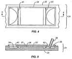
- the slide of the invention is shown in a top view in FIG. 4 , and in a vertical cross section in FIG. 5 taken along the line 5-5 of FIG. 4 .
- the slide 31 is shown in two parts -- a bottom plate 32 which serves as the floors of both the chamber (i.e., the cell counting section) and the reservoirs, and a top plate 33 which serves as the ceiling of the chamber and through which counting is performed.
- the slide 31 of FIGS. 4 and 5 contains two reservoirs 34, 35 with a platform 36 between them and a gap 37 between the platform 36 and the top plate 33 to serve as the chamber for cell counting.
- a pipette 38 is shown for use in the same manner as the pipette of FIG. 2 .
- the added feature in the embodiment of FIGS. 4 and 5 is a pair of dams 41, 42, one dam within each of the reservoirs 34, 35 along and parallel to the side of the reservoir closest to the platform, and extending the length of the reservoir.
- the dams 41, 42 serve to slow down the flow of the suspension toward the platform and improve the distribution of the suspension along the edges of the platform before passing over the edges into the cell counting section of the slide cavity.
- the dam thus produces a more even distribution of the cells in the cell counting area.
- a single reservoir can contain two or more dams, for example extending parallel to the edge of the platform 36.
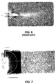
- FIG. 6 representing the prior art (lacking the reservoirs and the dams) and 7 representing the present invention (containing both the reservoirs and the dams).
- FIG. 6 representing the prior art (lacking the reservoirs and the dams)
- 7 representing the present invention (containing both the reservoirs and the dams).
- the images show that the cell slide of the prior art ( FIG. 6 ) has a lower concentration of cells at the center of the chamber, which thus appears lighter in contrast, while the cell slide of the invention ( FIG. 7 ) has an even distribution of cells across the length and width of the slide.
Landscapes
- Physics & Mathematics (AREA)
- Chemical & Material Sciences (AREA)
- Analytical Chemistry (AREA)
- General Physics & Mathematics (AREA)
- Optics & Photonics (AREA)
- Sampling And Sample Adjustment (AREA)
- Investigating Or Analysing Biological Materials (AREA)
- Microscoopes, Condenser (AREA)
- Apparatus Associated With Microorganisms And Enzymes (AREA)
Claims (12)
- Zellzähl-Objektträger (31), umfassend:eine im Wesentlichen flache Einschließung mit einem Hohlraum darin,wobei der Hohlraum umfasst:einen Zellzählabschnitt, der durch einen planaren Boden (36) und eine transparente planare Decke (33), die parallel zu dem Boden (36) ist und die durch eine Lücke (37) von dem Boden (36) getrennt ist, begrenzt ist, der eine Zellsuspension beherbergt und ausreichend dünn ist, um eine individuelle Beobachtung aller darin enthaltenen Zellen durch die Decke (33) hindurch zu ermöglichen;ein Reservoir (34, 35), das sich entlang der Länge einer Kante des Zellzählabschnitts erstreckt und eine Tiefe aufweist, die die Lücke (37) im Wesentlichen übertrifft, wobei sich das Reservoir unter dem planaren Boden (36) erstreckt und entlang der gesamten Länge zu dem Zellzählabschnitt hin offen ist; undeinen Anschluss (21, 22) in der Decke (33), der in das Reservoir (34, 35) einmündet;dadurch gekennzeichnet, dassder Zellzähl-Objektträger (31) weiterhin einen Damm (41, 42) innerhalb des Reservoirs (34, 35) umfasst, der so angeordnet ist, dass er den Fluss einer Zellsuspension aus dem Reservoir in den Zellzählabschnitt verlangsamt.
- Zellzähl-Objektträger (31) gemäß Anspruch 1, wobei der Hohlraum ein erstes und ein zweites Reservoir (34, 35), die sich entlang der Längen von einander gegenüberliegenden Kanten des Zellzählabschnitts erstrecken, sowie einen ersten und einen zweiten Anschluss (21, 22), wobei in jedes Reservoir (34, 35) einer der Anschlüsse (21, 22) einmündet, umfasst.
- Zellzähl-Objektträger (31) gemäß Anspruch 1, wobei die Lücke (37) eine Höhe aufweist und das Reservoir (34, 35) eine Tiefe aufweist, die wenigstens doppelt so groß wie die Höhe ist.
- Zellzähl-Objektträger (31) gemäß Anspruch 1, wobei der Zellzählabschnitt rechteckig mit zwei Längskanten und zwei seitlichen Kanten, die jeweils kürzer als die Längskanten sind, ist und sich das Reservoir (34, 35) entlang der Länge einer der seitlichen Kanten erstreckt.
- Zellzähl-Objektträger (31) gemäß Anspruch 2, wobei der Zellzählabschnitt rechteckig mit zwei Längskanten und zwei seitlichen Kanten, die jeweils kürzer als die Längskanten sind, ist, wobei sich entlang der Länge jeder der seitlichen Kanten eines der Reservoirs erstreckt.
- Zellzähl-Objektträger (31) gemäß Anspruch 1, wobei die Einschließung aus einer oberen und einer unteren Platte (33, 32) besteht, wobei die obere Platte (33) die Decke (33) bildet und die untere Platte (32) den Boden (36) und das Reservoir (34, 35) bildet, wenn die Platten (33, 32) aufeinander gelegt werden.
- Zellzähl-Objektträger gemäß Anspruch 1, wobei das Reservoir (34, 35) einen Boden hat und der Damm (41, 42) ein Grat in dem Reservoirboden parallel zu der Kante des Zellzählabschnitts und dieser benachbart ist.
- Zellzähl-Objektträger gemäß Anspruch 2, der weiterhin einen ersten Damm (41) innerhalb des ersten Reservoirs (34) und einen zweiten Damm (42) innerhalb des zweiten Reservoirs (35) umfasst, wobei jeder dieser Dämme (41, 42) parallel zu einem der einander gegenüberliegenden Kanten des Zellzählabschnitts und diesen benachbart angeordnet ist.
- Verfahren zum Zählen von Zellen in einer Zellsuspension, wobei das Verfahren umfasst:(a) Einbringen der Suspension in einen Zellzähl-Objektträger (31), umfassend:eine im Wesentlichen flache Einschließung mit einem Hohlraum darin, wobei der Hohlraum umfasst:einen Zellzählabschnitt, der durch einen planaren Boden (36) und eine transparente planare Decke (33), die parallel zu dem Boden (36) ist und die durch eine Lücke (37) von dem Boden (36) getrennt ist, begrenzt ist, der eine Zellsuspension beherbergt und ausreichend dünn ist, um eine individuelle Beobachtung aller darin enthaltenen Zellen durch die Decke (33) hindurch zu ermöglichen;ein Reservoir (34, 35), das sich entlang der Länge einer Kante des Zellzählabschnitts erstreckt und eine Tiefe aufweist, die die Lücke (37) im Wesentlichen übertrifft, wobei sich das Reservoir unter dem planaren Boden (36) erstreckt und entlang der gesamten Länge zu dem Zellzählabschnitt hin offen ist; undeinen Anschluss (21, 22) in der Decke (33), der in das Reservoir (34, 35) einmündet;dadurch, dass man die Suspension durch den Anschluss (21, 22) hindurch dem Reservoir (34, 35) so zuführt, dass das Reservoir (34, 35) gefüllt wird und bewirkt wird, dass die Suspension aus dem Reservoir (34, 35) in den Zellzählabschnitt überläuft; und(b) Untersuchen des Zellzählabschnitts durch die transparente planare Decke (33) hindurch, um Zellen in wenigstens einem Teil des Zellzählabschnitts zu zählen;dadurch gekennzeichnet, dass
der Zellzähl-Objektträger (31) weiterhin einen Damm (41, 42) innerhalb des Reservoirs (34, 35) umfasst und Schritt (a) weiterhin umfasst, dass man die Suspension über den Damm (41, 42) fließen lässt, damit sie in den Zellzählabschnitt eintritt. - Verfahren gemäß Anspruch 9, wobei:der Hohlraum ein erstes und ein zweites Reservoir (34, 35), die sich entlang der Längen von einander gegenüberliegenden Kanten des Zellzählabschnitts erstrecken, umfasst und sich der Damm (41) innerhalb des ersten Reservoirs (34) befindet;wobei der Zellzähl-Objektträger (31) einen ersten und einen zweiten Anschluss (21, 22), wobei in jedes Reservoir (34, 35) einer der Anschlüsse (21, 22) einmündet, umfasst; undSchritt (a) das Zuführen der Suspension durch den ersten Anschluss (21) in das erste Reservoir (34) umfasst, während durch den zweiten Anschluss (22) Luft aus dem Hohlraum abgelassen wird.
- Verfahren gemäß Anspruch 9, wobei der Zellzählabschnitt rechteckig mit zwei Längskanten und zwei seitlichen Kanten, die jeweils kürzer als die Längskanten sind, ist und sich das Reservoir (34, 35) entlang der Länge einer der seitlichen Kanten erstreckt.
- Verfahren gemäß Anspruch 10, wobei der Zellzählabschnitt rechteckig mit zwei Längskanten und zwei seitlichen Kanten, die jeweils kürzer als die Längskanten sind, ist, wobei sich das erste Reservoir (34) entlang der Länge einer der seitlichen Kanten erstreckt und sich das zweite Reservoir (35) entlang der Länge der anderen seitlichen Kante erstreckt.
Applications Claiming Priority (3)
| Application Number | Priority Date | Filing Date | Title |
|---|---|---|---|
| US29437310P | 2010-01-12 | 2010-01-12 | |
| US12/986,696 US8852524B2 (en) | 2010-01-12 | 2011-01-07 | Cell counting slide with lateral reservoir for promoting uniform cell distribution |
| PCT/US2011/020685 WO2011087988A1 (en) | 2010-01-12 | 2011-01-10 | Cell counting slide with lateral reservoir for promoting uniform cell distribution |
Publications (3)
| Publication Number | Publication Date |
|---|---|
| EP2524262A1 EP2524262A1 (de) | 2012-11-21 |
| EP2524262A4 EP2524262A4 (de) | 2013-11-27 |
| EP2524262B1 true EP2524262B1 (de) | 2016-04-06 |
Family
ID=44304596
Family Applications (1)
| Application Number | Title | Priority Date | Filing Date |
|---|---|---|---|
| EP11733236.1A Active EP2524262B1 (de) | 2010-01-12 | 2011-01-10 | Zellzählungsschieber mit seitlicher kammer zur förderung einer gleichförmigen zellverteilung |
Country Status (5)
| Country | Link |
|---|---|
| US (1) | US8852524B2 (de) |
| EP (1) | EP2524262B1 (de) |
| JP (1) | JP5559361B2 (de) |
| CA (1) | CA2786432C (de) |
| WO (1) | WO2011087988A1 (de) |
Families Citing this family (10)
| Publication number | Priority date | Publication date | Assignee | Title |
|---|---|---|---|---|
| US9001200B2 (en) | 2010-01-12 | 2015-04-07 | Bio-Rad Laboratories, Inc. | Cell characterization using multiple focus planes |
| US10114020B2 (en) | 2010-10-11 | 2018-10-30 | Mbio Diagnostics, Inc. | System and device for analyzing a fluidic sample |
| US9354155B2 (en) | 2011-05-31 | 2016-05-31 | Bio-Rad Laboratories, Inc. | Cell counting systems and methods |
| WO2014070235A1 (en) | 2012-10-29 | 2014-05-08 | Mbio Diagnostics, Inc. | Biological particle identification system, cartridge and associated methods |
| DK2914251T3 (da) | 2012-11-05 | 2019-11-04 | Us Health | Ketonlegemer til beskyttelse af væv mod beskadigelse som følge af ioniseringsstråling |
| KR101582412B1 (ko) * | 2014-05-19 | 2016-01-06 | 인제대학교 산학협력단 | 조직 검사대 |
| CN107805596A (zh) * | 2016-09-09 | 2018-03-16 | 东北农业大学 | 一种用于普通玻璃载玻片的细菌直接计数盒 |
| US10052754B1 (en) * | 2017-04-12 | 2018-08-21 | Ullman Devices Corporation | Magnetic tool holder |
| ES2863800T3 (es) * | 2017-12-22 | 2021-10-11 | Minitueb Gmbh | Procedimiento y dispositivos para analizar muestras de esperma |
| CN114561274A (zh) * | 2021-07-15 | 2022-05-31 | 上海萌薇生物医疗科技有限公司 | 一种由超声波焊接工艺合成的细胞计量板及其使用方法 |
Family Cites Families (16)
| Publication number | Priority date | Publication date | Assignee | Title |
|---|---|---|---|---|
| US4171866A (en) | 1978-04-20 | 1979-10-23 | Tolles Walter E | Disposable volumetric slide |
| US4466289A (en) | 1982-03-17 | 1984-08-21 | Lam Calvin K | Capacitance manometer with digital output |
| GB2127577B (en) * | 1982-09-20 | 1985-12-11 | V Tech Inc | Wet-mount microscopic examination slide |
| JPS63105715A (ja) | 1986-10-24 | 1988-05-11 | 松下電器産業株式会社 | 真空式電気保温ポツト |
| JPH0227111U (de) * | 1988-08-09 | 1990-02-22 | ||
| US5349436A (en) | 1992-12-02 | 1994-09-20 | Harry Fisch | Biological assembly |
| US5306467A (en) | 1993-02-17 | 1994-04-26 | Hamilton-Thorn Research | Apparatus for measurement of cell concentration in a biological sample employing a magnetic slide loading apparatus |
| JPH09236756A (ja) | 1996-02-29 | 1997-09-09 | Fukae Kasei Kk | 光学顕微鏡用プラスチック・スライド |
| US6165739A (en) | 1996-03-13 | 2000-12-26 | Compucyte Corporation | Multiple simultaneous testing media |
| TW587694U (en) * | 2003-03-14 | 2004-05-11 | Mau-Guei Jang | Protruded platform type quantitative cell counter plate |
| US7718124B2 (en) * | 2005-06-02 | 2010-05-18 | Minitube Of America, Inc. | Counting, viability assessment, analysis and manipulation chamber |
| US8711474B2 (en) | 2009-06-26 | 2014-04-29 | Bio-Rad Laboratories, Inc. | Modular microscope construction |
| US8570370B2 (en) | 2009-08-31 | 2013-10-29 | Bio-Rad Laboratories, Inc. | Compact automated cell counter |
| US9001200B2 (en) | 2010-01-12 | 2015-04-07 | Bio-Rad Laboratories, Inc. | Cell characterization using multiple focus planes |
| US8609363B2 (en) | 2010-11-18 | 2013-12-17 | Bio-Rad Laboratories, Inc. | Viability cell counting by differential light absorption |
| US9354155B2 (en) | 2011-05-31 | 2016-05-31 | Bio-Rad Laboratories, Inc. | Cell counting systems and methods |
-
2011
- 2011-01-07 US US12/986,696 patent/US8852524B2/en active Active
- 2011-01-10 JP JP2012548990A patent/JP5559361B2/ja not_active Expired - Fee Related
- 2011-01-10 EP EP11733236.1A patent/EP2524262B1/de active Active
- 2011-01-10 CA CA2786432A patent/CA2786432C/en active Active
- 2011-01-10 WO PCT/US2011/020685 patent/WO2011087988A1/en not_active Ceased
Also Published As
| Publication number | Publication date |
|---|---|
| US20120015392A1 (en) | 2012-01-19 |
| CA2786432C (en) | 2016-03-22 |
| EP2524262A4 (de) | 2013-11-27 |
| WO2011087988A1 (en) | 2011-07-21 |
| CA2786432A1 (en) | 2011-07-21 |
| JP2013517529A (ja) | 2013-05-16 |
| EP2524262A1 (de) | 2012-11-21 |
| US8852524B2 (en) | 2014-10-07 |
| JP5559361B2 (ja) | 2014-07-23 |
Similar Documents
| Publication | Publication Date | Title |
|---|---|---|
| EP2524262B1 (de) | Zellzählungsschieber mit seitlicher kammer zur förderung einer gleichförmigen zellverteilung | |
| EP0800571B1 (de) | Biologische analytische vorrichtung mit verbesserter verhinderung von kontamination | |
| EP1949310B1 (de) | Verfahren zum durchführen von zählungen in einer biologischen fluidprobe | |
| EP3148700B1 (de) | Einspaltiges mikroplattensystem und träger zur analyse biologischer proben | |
| JP3907624B2 (ja) | マルチウェルフィルタプレートに供給するためのアクセスホール | |
| US6819408B1 (en) | Method for obtaining a monolayer of desired particles in a liquid sample | |
| US7820451B2 (en) | Analytical test element | |
| EP0210071B1 (de) | Mikroskop-Objektträger | |
| JP2009512859A5 (de) | ||
| US20060099570A1 (en) | Device and method for non-invasive measurement of the individual metabolic rate of a substantially spherical metabolizing particle | |
| EP2270573B1 (de) | Deckel für Zählung, Beurteilung der Lebensfähigkeit, Analyse und Manipulation | |
| JP4077950B2 (ja) | 蓋付き容器 | |
| USRE33826E (en) | Microscope inspection slide | |
| US7005008B2 (en) | Reaction vessel | |
| US20250019636A1 (en) | Device for separating motile cells | |
| CN215986705U (zh) | 一种载玻片 | |
| EP3919172A1 (de) | Mikrofluidische vorrichtung | |
| JP2026027734A (ja) | 補助部材および観察方法 | |
| US20020093735A1 (en) | Slide for the microscopic examination of biological fluids | |
| US20230003748A1 (en) | Device for Testing Blood Plasma | |
| US20250257301A1 (en) | Microfluidic apparatus | |
| JP2024541272A (ja) | ウェルプレート装置及びその充填方法 | |
| CN113946045A (zh) | 一种载玻片及载玻片的使用方法 |
Legal Events
| Date | Code | Title | Description |
|---|---|---|---|
| PUAI | Public reference made under article 153(3) epc to a published international application that has entered the european phase |
Free format text: ORIGINAL CODE: 0009012 |
|
| 17P | Request for examination filed |
Effective date: 20120705 |
|
| AK | Designated contracting states |
Kind code of ref document: A1 Designated state(s): AL AT BE BG CH CY CZ DE DK EE ES FI FR GB GR HR HU IE IS IT LI LT LU LV MC MK MT NL NO PL PT RO RS SE SI SK SM TR |
|
| DAX | Request for extension of the european patent (deleted) | ||
| A4 | Supplementary search report drawn up and despatched |
Effective date: 20131025 |
|
| RIC1 | Information provided on ipc code assigned before grant |
Ipc: G02B 21/34 20060101AFI20131021BHEP |
|
| GRAP | Despatch of communication of intention to grant a patent |
Free format text: ORIGINAL CODE: EPIDOSNIGR1 |
|
| INTG | Intention to grant announced |
Effective date: 20151009 |
|
| GRAS | Grant fee paid |
Free format text: ORIGINAL CODE: EPIDOSNIGR3 |
|
| GRAA | (expected) grant |
Free format text: ORIGINAL CODE: 0009210 |
|
| AK | Designated contracting states |
Kind code of ref document: B1 Designated state(s): AL AT BE BG CH CY CZ DE DK EE ES FI FR GB GR HR HU IE IS IT LI LT LU LV MC MK MT NL NO PL PT RO RS SE SI SK SM TR |
|
| REG | Reference to a national code |
Ref country code: GB Ref legal event code: FG4D |
|
| REG | Reference to a national code |
Ref country code: AT Ref legal event code: REF Ref document number: 788403 Country of ref document: AT Kind code of ref document: T Effective date: 20160415 Ref country code: CH Ref legal event code: EP |
|
| REG | Reference to a national code |
Ref country code: IE Ref legal event code: FG4D |
|
| REG | Reference to a national code |
Ref country code: DE Ref legal event code: R096 Ref document number: 602011024928 Country of ref document: DE |
|
| REG | Reference to a national code |
Ref country code: LT Ref legal event code: MG4D Ref country code: NL Ref legal event code: MP Effective date: 20160406 |
|
| REG | Reference to a national code |
Ref country code: AT Ref legal event code: MK05 Ref document number: 788403 Country of ref document: AT Kind code of ref document: T Effective date: 20160406 |
|
| PG25 | Lapsed in a contracting state [announced via postgrant information from national office to epo] |
Ref country code: NL Free format text: LAPSE BECAUSE OF FAILURE TO SUBMIT A TRANSLATION OF THE DESCRIPTION OR TO PAY THE FEE WITHIN THE PRESCRIBED TIME-LIMIT Effective date: 20160406 |
|
| PG25 | Lapsed in a contracting state [announced via postgrant information from national office to epo] |
Ref country code: IS Free format text: LAPSE BECAUSE OF FAILURE TO SUBMIT A TRANSLATION OF THE DESCRIPTION OR TO PAY THE FEE WITHIN THE PRESCRIBED TIME-LIMIT Effective date: 20160806 Ref country code: NO Free format text: LAPSE BECAUSE OF FAILURE TO SUBMIT A TRANSLATION OF THE DESCRIPTION OR TO PAY THE FEE WITHIN THE PRESCRIBED TIME-LIMIT Effective date: 20160706 Ref country code: LT Free format text: LAPSE BECAUSE OF FAILURE TO SUBMIT A TRANSLATION OF THE DESCRIPTION OR TO PAY THE FEE WITHIN THE PRESCRIBED TIME-LIMIT Effective date: 20160406 Ref country code: FI Free format text: LAPSE BECAUSE OF FAILURE TO SUBMIT A TRANSLATION OF THE DESCRIPTION OR TO PAY THE FEE WITHIN THE PRESCRIBED TIME-LIMIT Effective date: 20160406 Ref country code: PL Free format text: LAPSE BECAUSE OF FAILURE TO SUBMIT A TRANSLATION OF THE DESCRIPTION OR TO PAY THE FEE WITHIN THE PRESCRIBED TIME-LIMIT Effective date: 20160406 |
|
| PG25 | Lapsed in a contracting state [announced via postgrant information from national office to epo] |
Ref country code: PT Free format text: LAPSE BECAUSE OF FAILURE TO SUBMIT A TRANSLATION OF THE DESCRIPTION OR TO PAY THE FEE WITHIN THE PRESCRIBED TIME-LIMIT Effective date: 20160808 Ref country code: SE Free format text: LAPSE BECAUSE OF FAILURE TO SUBMIT A TRANSLATION OF THE DESCRIPTION OR TO PAY THE FEE WITHIN THE PRESCRIBED TIME-LIMIT Effective date: 20160406 Ref country code: LV Free format text: LAPSE BECAUSE OF FAILURE TO SUBMIT A TRANSLATION OF THE DESCRIPTION OR TO PAY THE FEE WITHIN THE PRESCRIBED TIME-LIMIT Effective date: 20160406 Ref country code: AT Free format text: LAPSE BECAUSE OF FAILURE TO SUBMIT A TRANSLATION OF THE DESCRIPTION OR TO PAY THE FEE WITHIN THE PRESCRIBED TIME-LIMIT Effective date: 20160406 Ref country code: RS Free format text: LAPSE BECAUSE OF FAILURE TO SUBMIT A TRANSLATION OF THE DESCRIPTION OR TO PAY THE FEE WITHIN THE PRESCRIBED TIME-LIMIT Effective date: 20160406 Ref country code: ES Free format text: LAPSE BECAUSE OF FAILURE TO SUBMIT A TRANSLATION OF THE DESCRIPTION OR TO PAY THE FEE WITHIN THE PRESCRIBED TIME-LIMIT Effective date: 20160406 Ref country code: GR Free format text: LAPSE BECAUSE OF FAILURE TO SUBMIT A TRANSLATION OF THE DESCRIPTION OR TO PAY THE FEE WITHIN THE PRESCRIBED TIME-LIMIT Effective date: 20160707 Ref country code: HR Free format text: LAPSE BECAUSE OF FAILURE TO SUBMIT A TRANSLATION OF THE DESCRIPTION OR TO PAY THE FEE WITHIN THE PRESCRIBED TIME-LIMIT Effective date: 20160406 |
|
| PG25 | Lapsed in a contracting state [announced via postgrant information from national office to epo] |
Ref country code: IT Free format text: LAPSE BECAUSE OF FAILURE TO SUBMIT A TRANSLATION OF THE DESCRIPTION OR TO PAY THE FEE WITHIN THE PRESCRIBED TIME-LIMIT Effective date: 20160406 Ref country code: BE Free format text: LAPSE BECAUSE OF FAILURE TO SUBMIT A TRANSLATION OF THE DESCRIPTION OR TO PAY THE FEE WITHIN THE PRESCRIBED TIME-LIMIT Effective date: 20160406 |
|
| REG | Reference to a national code |
Ref country code: DE Ref legal event code: R097 Ref document number: 602011024928 Country of ref document: DE |
|
| REG | Reference to a national code |
Ref country code: FR Ref legal event code: PLFP Year of fee payment: 7 |
|
| PG25 | Lapsed in a contracting state [announced via postgrant information from national office to epo] |
Ref country code: EE Free format text: LAPSE BECAUSE OF FAILURE TO SUBMIT A TRANSLATION OF THE DESCRIPTION OR TO PAY THE FEE WITHIN THE PRESCRIBED TIME-LIMIT Effective date: 20160406 Ref country code: DK Free format text: LAPSE BECAUSE OF FAILURE TO SUBMIT A TRANSLATION OF THE DESCRIPTION OR TO PAY THE FEE WITHIN THE PRESCRIBED TIME-LIMIT Effective date: 20160406 Ref country code: CZ Free format text: LAPSE BECAUSE OF FAILURE TO SUBMIT A TRANSLATION OF THE DESCRIPTION OR TO PAY THE FEE WITHIN THE PRESCRIBED TIME-LIMIT Effective date: 20160406 Ref country code: RO Free format text: LAPSE BECAUSE OF FAILURE TO SUBMIT A TRANSLATION OF THE DESCRIPTION OR TO PAY THE FEE WITHIN THE PRESCRIBED TIME-LIMIT Effective date: 20160406 Ref country code: SK Free format text: LAPSE BECAUSE OF FAILURE TO SUBMIT A TRANSLATION OF THE DESCRIPTION OR TO PAY THE FEE WITHIN THE PRESCRIBED TIME-LIMIT Effective date: 20160406 |
|
| PLBE | No opposition filed within time limit |
Free format text: ORIGINAL CODE: 0009261 |
|
| STAA | Information on the status of an ep patent application or granted ep patent |
Free format text: STATUS: NO OPPOSITION FILED WITHIN TIME LIMIT |
|
| PG25 | Lapsed in a contracting state [announced via postgrant information from national office to epo] |
Ref country code: SM Free format text: LAPSE BECAUSE OF FAILURE TO SUBMIT A TRANSLATION OF THE DESCRIPTION OR TO PAY THE FEE WITHIN THE PRESCRIBED TIME-LIMIT Effective date: 20160406 |
|
| 26N | No opposition filed |
Effective date: 20170110 |
|
| PG25 | Lapsed in a contracting state [announced via postgrant information from national office to epo] |
Ref country code: SI Free format text: LAPSE BECAUSE OF FAILURE TO SUBMIT A TRANSLATION OF THE DESCRIPTION OR TO PAY THE FEE WITHIN THE PRESCRIBED TIME-LIMIT Effective date: 20160406 |
|
| REG | Reference to a national code |
Ref country code: CH Ref legal event code: PL |
|
| PG25 | Lapsed in a contracting state [announced via postgrant information from national office to epo] |
Ref country code: MC Free format text: LAPSE BECAUSE OF FAILURE TO SUBMIT A TRANSLATION OF THE DESCRIPTION OR TO PAY THE FEE WITHIN THE PRESCRIBED TIME-LIMIT Effective date: 20160406 |
|
| PG25 | Lapsed in a contracting state [announced via postgrant information from national office to epo] |
Ref country code: LI Free format text: LAPSE BECAUSE OF NON-PAYMENT OF DUE FEES Effective date: 20170131 Ref country code: CH Free format text: LAPSE BECAUSE OF NON-PAYMENT OF DUE FEES Effective date: 20170131 |
|
| REG | Reference to a national code |
Ref country code: IE Ref legal event code: MM4A |
|
| PG25 | Lapsed in a contracting state [announced via postgrant information from national office to epo] |
Ref country code: LU Free format text: LAPSE BECAUSE OF NON-PAYMENT OF DUE FEES Effective date: 20170110 |
|
| REG | Reference to a national code |
Ref country code: FR Ref legal event code: PLFP Year of fee payment: 8 |
|
| PG25 | Lapsed in a contracting state [announced via postgrant information from national office to epo] |
Ref country code: IE Free format text: LAPSE BECAUSE OF NON-PAYMENT OF DUE FEES Effective date: 20170110 |
|
| PG25 | Lapsed in a contracting state [announced via postgrant information from national office to epo] |
Ref country code: MT Free format text: LAPSE BECAUSE OF NON-PAYMENT OF DUE FEES Effective date: 20170110 |
|
| PG25 | Lapsed in a contracting state [announced via postgrant information from national office to epo] |
Ref country code: AL Free format text: LAPSE BECAUSE OF FAILURE TO SUBMIT A TRANSLATION OF THE DESCRIPTION OR TO PAY THE FEE WITHIN THE PRESCRIBED TIME-LIMIT Effective date: 20160406 |
|
| PG25 | Lapsed in a contracting state [announced via postgrant information from national office to epo] |
Ref country code: HU Free format text: LAPSE BECAUSE OF FAILURE TO SUBMIT A TRANSLATION OF THE DESCRIPTION OR TO PAY THE FEE WITHIN THE PRESCRIBED TIME-LIMIT; INVALID AB INITIO Effective date: 20110110 |
|
| PG25 | Lapsed in a contracting state [announced via postgrant information from national office to epo] |
Ref country code: BG Free format text: LAPSE BECAUSE OF FAILURE TO SUBMIT A TRANSLATION OF THE DESCRIPTION OR TO PAY THE FEE WITHIN THE PRESCRIBED TIME-LIMIT Effective date: 20160406 |
|
| PG25 | Lapsed in a contracting state [announced via postgrant information from national office to epo] |
Ref country code: CY Free format text: LAPSE BECAUSE OF NON-PAYMENT OF DUE FEES Effective date: 20160406 |
|
| PG25 | Lapsed in a contracting state [announced via postgrant information from national office to epo] |
Ref country code: MK Free format text: LAPSE BECAUSE OF FAILURE TO SUBMIT A TRANSLATION OF THE DESCRIPTION OR TO PAY THE FEE WITHIN THE PRESCRIBED TIME-LIMIT Effective date: 20160406 |
|
| PG25 | Lapsed in a contracting state [announced via postgrant information from national office to epo] |
Ref country code: TR Free format text: LAPSE BECAUSE OF FAILURE TO SUBMIT A TRANSLATION OF THE DESCRIPTION OR TO PAY THE FEE WITHIN THE PRESCRIBED TIME-LIMIT Effective date: 20160406 |
|
| P01 | Opt-out of the competence of the unified patent court (upc) registered |
Effective date: 20230510 |
|
| PGFP | Annual fee paid to national office [announced via postgrant information from national office to epo] |
Ref country code: GB Payment date: 20260126 Year of fee payment: 16 |
|
| PGFP | Annual fee paid to national office [announced via postgrant information from national office to epo] |
Ref country code: DE Payment date: 20260127 Year of fee payment: 16 |
|
| PGFP | Annual fee paid to national office [announced via postgrant information from national office to epo] |
Ref country code: FR Payment date: 20260127 Year of fee payment: 16 |