EP2523797B1 - Siebträgerelement für eine filtriereinrichtung mit wenigstens einer siebkavität - Google Patents
Siebträgerelement für eine filtriereinrichtung mit wenigstens einer siebkavität Download PDFInfo
- Publication number
- EP2523797B1 EP2523797B1 EP11701217.9A EP11701217A EP2523797B1 EP 2523797 B1 EP2523797 B1 EP 2523797B1 EP 11701217 A EP11701217 A EP 11701217A EP 2523797 B1 EP2523797 B1 EP 2523797B1
- Authority
- EP
- European Patent Office
- Prior art keywords
- screen
- carrier element
- supporting tube
- filter elements
- disc filter
- Prior art date
- Legal status (The legal status is an assumption and is not a legal conclusion. Google has not performed a legal analysis and makes no representation as to the accuracy of the status listed.)
- Active
Links
Images

Classifications
-
- B—PERFORMING OPERATIONS; TRANSPORTING
- B01—PHYSICAL OR CHEMICAL PROCESSES OR APPARATUS IN GENERAL
- B01D—SEPARATION
- B01D29/00—Filters with filtering elements stationary during filtration, e.g. pressure or suction filters, not covered by groups B01D24/00 - B01D27/00; Filtering elements therefor
- B01D29/39—Filters with filtering elements stationary during filtration, e.g. pressure or suction filters, not covered by groups B01D24/00 - B01D27/00; Filtering elements therefor with hollow discs side by side on, or around, one or more tubes, e.g. of the leaf type
- B01D29/41—Filters with filtering elements stationary during filtration, e.g. pressure or suction filters, not covered by groups B01D24/00 - B01D27/00; Filtering elements therefor with hollow discs side by side on, or around, one or more tubes, e.g. of the leaf type mounted transversely on the tube
-
- B—PERFORMING OPERATIONS; TRANSPORTING
- B29—WORKING OF PLASTICS; WORKING OF SUBSTANCES IN A PLASTIC STATE IN GENERAL
- B29C—SHAPING OR JOINING OF PLASTICS; SHAPING OF MATERIAL IN A PLASTIC STATE, NOT OTHERWISE PROVIDED FOR; AFTER-TREATMENT OF THE SHAPED PRODUCTS, e.g. REPAIRING
- B29C48/00—Extrusion moulding, i.e. expressing the moulding material through a die or nozzle which imparts the desired form; Apparatus therefor
- B29C48/25—Component parts, details or accessories; Auxiliary operations
- B29C48/36—Means for plasticising or homogenising the moulding material or forcing it through the nozzle or die
- B29C48/50—Details of extruders
- B29C48/69—Filters or screens for the moulding material
- B29C48/694—Cylindrical or conical filters
-
- B—PERFORMING OPERATIONS; TRANSPORTING
- B29—WORKING OF PLASTICS; WORKING OF SUBSTANCES IN A PLASTIC STATE IN GENERAL
- B29C—SHAPING OR JOINING OF PLASTICS; SHAPING OF MATERIAL IN A PLASTIC STATE, NOT OTHERWISE PROVIDED FOR; AFTER-TREATMENT OF THE SHAPED PRODUCTS, e.g. REPAIRING
- B29C48/00—Extrusion moulding, i.e. expressing the moulding material through a die or nozzle which imparts the desired form; Apparatus therefor
- B29C48/03—Extrusion moulding, i.e. expressing the moulding material through a die or nozzle which imparts the desired form; Apparatus therefor characterised by the shape of the extruded material at extrusion
-
- B—PERFORMING OPERATIONS; TRANSPORTING
- B29—WORKING OF PLASTICS; WORKING OF SUBSTANCES IN A PLASTIC STATE IN GENERAL
- B29C—SHAPING OR JOINING OF PLASTICS; SHAPING OF MATERIAL IN A PLASTIC STATE, NOT OTHERWISE PROVIDED FOR; AFTER-TREATMENT OF THE SHAPED PRODUCTS, e.g. REPAIRING
- B29C48/00—Extrusion moulding, i.e. expressing the moulding material through a die or nozzle which imparts the desired form; Apparatus therefor
- B29C48/25—Component parts, details or accessories; Auxiliary operations
- B29C48/36—Means for plasticising or homogenising the moulding material or forcing it through the nozzle or die
- B29C48/50—Details of extruders
- B29C48/69—Filters or screens for the moulding material
- B29C48/693—Substantially flat filters mounted at the end of an extruder screw perpendicular to the feed axis
Definitions
- the invention relates to a filter element for a filter device having at least one screen cavity, in which at least one filter unit is to be arranged, which comprises a support tube with recesses and a plurality of disc filter elements, wherein the disc filter elements each have at least one central hub, with which they are mounted on the support tube, and a surrounding the hub, semi-permeable filter medium, which is spanned into a three-dimensional structure, wherein in the hub member at least one flow channel from the spanned by the filter medium volume to the support tube and wherein the support tube opens into an outlet channel of the Siebryelements.
- the object of the invention is therefore to develop a Siebmelelement of the type mentioned so that the replacement of the filter units on the Siebongettin is facilitated.
- the support tube has a projecting below the disc filter elements projecting bearing portion which can be inserted from the Siebkavtician in the outlet channel and that the outlet channel is formed over at least a portion of its length as a tapered bore which opens in the direction of Siebkavtician, wherein the bearing portion of the support tube has at least one conical portion which engages in the at least one conical bore.
- the assembly is very simple, since the filter unit needs to be inserted only with the outstanding below from the package of disc filter elements bearing portion in the outlet channel.
- the at least one conical section at the lower part of the support tube is thereby inserted into the at least partially formed as a conical bore outlet channel.
- the support tube is axially fixed and at the same time a seal against the Siebangoelement is effected on the entire circumference of the conical portion.
- the melt pressure acts on the filter unit it becomes conical with the conical portion of the support tube Area of the outlet channel pressed without the application of a bias voltage is required.
- the plug-in assembly provided according to the invention results in a further advantage that the support tube is not loaded by torsion. While according to the prior art, the entire filter unit is to be screwed into the Siebaelement, wherein the support tube must transmit the tightening torque, eliminated in the Siebegaelement of the invention, such a heavy load on the support tube. Deformations of the support tube and consequent leaks in the filter unit used are avoided.
- the disassembly is significantly facilitated in the Siebaelement invention, characterized in that the entire filter unit can be pressed from the output side of the Siebaelements ago ago by looking from behind presses on the exposed there end portion of the support tube.
- a percussion tool which acts against the end face of the support tube or which is inserted into the central bore in the support tube and then acts from the inside against a tapered portion therein.
- At least one annular sealing surface is formed on at least one of the end faces of the hubs of the disc filter elements, which protrudes in the axial direction over the laterally attached to the remaining part of the hub filter medium.
- the annular sealing surfaces of the juxtaposed disc filter elements lie against each other.
- the sealing surfaces may be ground, for example, so that there is a high plane parallelism of adjacent sealing surfaces.
- metallic sealing rings are inserted between the annular sealing surfaces are, which may for example consist of a metal fiber fleece.
- the hubs of the disc filter elements are pressed against each other by means of a securing element that can be attached to the end of the support tube projecting into the screen cavity.
- a baffle plate can be provided, which is arranged in front of the disc filter element of the filter unit located at the top in the screen cavity. It guides the melt homogeneously into the annular gap which extends around the disc filter elements and ensures a uniform pressure distribution in the screen cavity.
- the baffle plate can be pressed by means of the securing element on the stacked disc filter elements.
- the baffle plate forms the uppermost element in the stack with the disc filter elements.
- the Siebmelelement is preferably formed as a round Siebpasbolzen which is part of a filtration device for filtering a fluid, primarily for the filtration of polymer melts.
- a housing at least one Siebforementionedbohrung is introduced, in which the Sieblicbolzen is slidably mounted.
- the Siebforementionedelement can also be a rectangular plate.
- the securing element has in particular a threaded shoulder which can be screwed into a threaded bore in the support tube.
- the threaded bore can be introduced within a Verdrängerkonus. This is arranged in the area within the support tube and has with its pointed end to the output side.
- the displacer cone prevents the formation of a dead water zone in the end region of the support tube and thereby prevents melt or other filtered material from depositing and decomposing in this region.
- the formation of the support tube can be round. Then flow paths must be created from the mouths of the flow channels on the inner circumference of the hubs to the recesses in the jacket of the support tube. This can be achieved by grooves applied to the outer jacket or grooves introduced into the outer circumference
- the support tube has a polygonal cross section.
- the hole in the hub should be cylindrical.
- the recess in the hub could be designed polygonal and the shell of the tube be cylindrical.
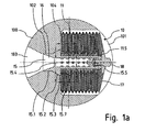
- FIG. 1a shows in a sectional view a Siebmbolzen 100, which has a Siebkavmaschine 101.
- the inner contour of the outlet channel 102 thus described corresponds to the outer contour at an end of a support tube 15 of a filter unit 10, which is designated here as a bearing section.
- the bearing section thus comprises two cylindrical sections 15.1, 15.3 and an intermediate conical section 15.2.
- the hollow support tube 15 widens at its end inside to a conical bore 16, wherein the cone angle of the bore 16 preferably also corresponds to the cone angle at the outlet opening 103, so that there is a stepless transition.
- the largest part of the filter unit 10 is arranged.
- a plurality of annular disc filter elements 11 are pushed with their respective central hub 11.5 on the support tube 15.
- the package of filter elements 11 is fixed axially to a shoulder 15.7 on the support tube 15.
- a baffle plate 17 is arranged, which covers the disc filter element 11 located at the top in the stack.
- a securing element 18 is screwed into the support tube 15 and thereby presses the baffle plate against the metallic hubs 11.5 of the disc filter elements 11 and the entire stack against the shoulder 15.7.
- the support tube 15 has in its jacket a plurality of recesses 15.4, which allow the passage of the melt from the interior of the respective disc filter elements 11 into the central bore in the support tube 15.
- a Verdrängerkonus 15.5 in the support tube 15 improves the flow behavior of the filtered medium in the end.
- FIG. 1b shows a taken from the Siebmixelement 100 filter unit 10 in a perspective view View of the bearing section of the support tube 15. Clearly visible here are the cylindrical sections 15.1, 15.3 and the intermediate conical section 15.2.
- a hole 15.6 is visible in the conical section 15.2 .
- Another bore is arranged diametrically opposite to the conical section 15.2.
- the holes 15.6 serve as mounting aid. It can be attached to a suitable key tool to counteract the torque that arises when tightening or loosening the fuse element.
- the securing element presses on the other end of the support tube to the disc filter elements. As a result, the filter unit need not be held with clamps on its bearing shoulder or even clamped in a vise, which could damage the conical sealing surface.
- a spacer 11.2 serves to allow the homogeneous flow of a thin, semi-permeable filter medium.
- the filter medium may be, for example, a woven fabric or a web of metal threads. Through the filter medium, a hollow body is clamped.
- the medium to be filtered passes through the filter medium into the main body of the respective disc filter element 11 and then through a flow channel 11.4 in the hub 11.5 and flows through the recesses 15.4 into the interior of the support tube 15th
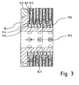
- FIG. 3 shows an enlargement of the in FIG. 1a with a dot-dash line framed part. This is the area in which the first four disc filter elements 11 are pressed against the shoulder 15.7 of the support tube 15.
- the annular hub 11.5 has two outside paragraphs with less axial extent than the paragraph inside.
- the outer heels serve to ensure that the filter medium 11.1 and / or the spacer 11.2 protrude in the axial direction beyond the sealing surfaces 11.8 on the hub 11.5, and a homogeneous distance between the individual filter elements, which is determined by the heel height and the thickness of the spacer. is available.
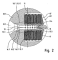
- FIG. 2 shows a further embodiment of a Siebyelements 100 'with a filter unit 10'.
- a Siebyelements 100 Different from the previously described embodiment of a Siebyelements 100 is only that an outlet channel 102 'is formed throughout as a tapered hole and that corresponding to the bearing portion of the support tube 15' only a continuous cone portion 15.1 'is formed.
- the support tube 15 Inside, the support tube 15 'at its output end two conical sections 16.1', 16.3 'and an intermediate cylindrical section 16.2' on.
- the remaining areas of the filter unit 10 'with the disc filter elements 11 are constructed in the same manner as described in the first embodiment.
Landscapes
- Engineering & Computer Science (AREA)
- Mechanical Engineering (AREA)
- Chemical & Material Sciences (AREA)
- Chemical Kinetics & Catalysis (AREA)
- Filtration Of Liquid (AREA)
- Filtering Materials (AREA)
- Extrusion Moulding Of Plastics Or The Like (AREA)
- Filtering Of Dispersed Particles In Gases (AREA)
Description
- Die Erfindung betrifft ein Siebträgerelement für eine Filtriereinrichtung mit wenigstens einer Siebkavität, in der wenigstens eine Filtereinheit anzuordnen ist, welche ein Stützrohr mit Ausnehmungen und mehrere Scheibenfilterelemente umfasst, wobei die Scheibenfilterelemente jeweils wenigstens eine zentrale Nabe aufweisen, mit welcher sie auf dem Stützrohr gelagert sind, und ein die Nabe umgebendes, halbdurchlässiges Filtermedium, das zu einem dreidimensionalen Gebilde aufgespannt ist, wobei sich in dem Nabenelement wenigstens ein Fließkanal von dem durch das Filtermedium umspannten Volumen bis zum Stützrohr erstreckt und wobei das Stützrohr in einem Austrittskanal des Siebträgerelements mündet.
- Ein solches Siebträgerelement ist in der
DE 10 2007 006 811 A1 beschrieben. Die aufeinander gestapelten Scheibenfilterelemente führen zu einer deutlichen Vergrößerung der Filterfläche, ohne dass die Siebkavität zur Aufnahme der Filtereinheit vergrößert zu werden braucht. - Bei dem bekannten Siebträgerelement ist das Stützrohr in eine Zwischenplatte eingeschraubt und es dient gleichzeitig dazu, gegeneinander geschichtete Scheibenträgerelemente gegen die Zwischenplatte zu pressen. Die Zwischenplatte ist in eine Ausnehmung am Grund der Siebkavität eingesetzt ist. Hieraus ergeben sich mehrere Nachteile:
- Die dicke Zwischenplatte nimmt eine Bauhöhe im Siebträgerelement ein, die etwa 3-4 übereinandergeschichteten Scheibenfilterelementen entspricht. Entsprechend ist die Zahl der Scheibenfilterelemente geringer als sie nach dem Volumen der Siebkavität sein könnte
- Das in die Zwischenplatte eingeschraubte Stützrohr wird bei einem Schmelzezufluss, der von außerhalb des Zentrums der Siebkavität und nicht orthogonal erfolgt, auf Biegung beansprucht. Kommt es dadurch zu Verformungen am Stützrohr, kann das zum Wechseln der Schadenfilterelemente erforderliche Herausschrauben erschwert oder verhindert werden.
- In jedem Fall nimmt die montageunfreundliche Schraubverbindung des Stützrohrs den Zeitvorteil, den wechselbare Siebträgerelemente in Filtereinrichtungen bringen.
- Die Zwischenplatte und der Boden der Aufnahme müssen eine hohe Planparallelität aufweisen, da ansonsten keine Dichtigkeit gewährleistet ist.
- Die Demontage der Filtereinheit ist erschwert, wenn die Zwischenplatte in der zylindrischen Vertiefung im Siebbolzen verkantet oder durch in den Spalt eingedrungene Kunststoffreste blockiert ist.
- Weitere Siebträgerelemente für eine Filtriereinrichtung sind aus der
EP 0 728 512 A2 und derDE 29 520 418 U1 bekannt. - Aufgabe der Erfindung ist es daher, ein Siebträgerelement der eingangs genannten Art so weiterzuentwickeln, dass der Austausch der Filtereinheiten an den Siebträgerelementen erleichtert ist.
- Diese Aufgabe wird gemäß der vorliegenden Erfindung dadurch gelöst, dass das Stützrohr einen unterhalb der Scheibenfilterelemente hervor ragenden Lagerabschnitt aufweist, der von der Siebkavität aus in den Austrittskanal einsteckbar ist und dass der Austrittskanal über wenigstens einen Teil seiner Länge als eine Kegelbohrung ausgebildet ist, welche sich in Richtung der Siebkavität öffnet, wobei der Lagerabschnitt des Stützrohrs wenigstens einen Kegelabschnitt aufweist, der in die wenigstens eine Kegelbohrung eingreift.
- Dadurch, dass das Stützrohr der Filtereinheit im Austrittskanal des Siebträgers gelagert ist, können Hebelkräfte aus dem Schmelzefluss abgefangen werden, wenn die Schmelze nicht zentral und orthogonal auf die Filtereinheit zugeleitet wird.
- Die Montage ist sehr einfach, da die Filtereinheit lediglich mit dem unten aus dem Paket von Scheibenfilterelementen herausragenden Lagerabschnitt in den Austrittskanal eingeschoben zu werden braucht.
- Der wenigstens eine Kegelabschnitt am unteren Teil des Stützrohrs wird dabei in den zumindest teilweise als Kegelbohrung ausgebildeten Austrittskanal eingeschoben. Dadurch wird das Stützrohr axial festgelegt und zugleich wird am gesamten Umfang des Kegelabschnitts eine Abdichtung gegenüber dem Siebträgerelement bewirkt. Sobald der Schmelzedruck auf die Filtereinheit wirkt, wird diese mit dem Kegelabschnitt des Stützrohrs in den kegelförmigen Bereich des Austrittskanals gepresst, ohne dass zuvor das Aufbringen einer Vorspannung erforderlich ist.
- Die Anordnung des Kegelabschnitts am Stützrohr kann in verschiedener Weise erfolgend:
- Der Lagerabschnitt des Stützrohrs kann ein zylindrisches Ende aufweisen und einen sich daran anschließenden Kegelabschnitt.
- Der Lagerabschnitt des Stützrohrs kann auch ein zylindrisches Ende aufweisen, einen sich daran anschließenden Kegelabschnitt und einen sich wiederum daran anschließenden, weiteren zylindrischen Abschnitt.
- Schließlich kann der Lagerabschnitt des Stützrohrs vollständig als Kegelabschnitt ausgebildet sein.
- Wesentlich ist nur, dass ein Kegelabschnitt vorhanden ist, der die Dichtung und axiale Festlegung bewirkt.
- Durch die nach der Erfindung vorgesehenen Steckmontage ergibt sich als weiterer Vorteil, dass das Stützrohr nicht durch Torsion belastet wird. Während gemäß dem Stand der Technik die gesamte Filtereinheit in das Siebträgerelement einzuschrauben ist, wobei das Stützrohr das Anzugsdrehmoment übertragen muss, entfällt bei dem Siebträgerelement der Erfindung eine solche starke Belastung des Stützrohrs. Verformungen des Stützrohrs und dadurch bedingte Undichtigkeiten der eingesetzten Filtereinheit werden vermieden.
- Die Demontage ist bei dem erfindungsgemäßen Siebträgerelement dadurch wesentlich erleichtert, dass die gesamte Filtereinheit von der Ausgangsseite des Siebträgerelements her heraus gedrückt werden kann, indem man von hinten auf den dort offen liegenden Endabschnitt des Stützrohrs drückt.
- Sollte die Filtereinheit einmal fest sitzen, kann von der Ausgangsseite des Siebträgerelements auch ein Schlagwerkzeug angesetzt werden, das gegen die Stirnfläche des Stützrohrs wirkt oder das in die zentrale Bohrung im Stützrohr gesteckt wird und dann von innen gegen einen sich verjüngenden Abschnitt darin wirkt.
- Es wird außerdem bei dem erfindungsgemäßen Siebträgerelement der sonst im Stand der Technik für die Stützplatte benötigte Bauraum eingespart, so dass weitere Scheibenfilterelemente in die Filtereinheit integriert werden können und die wirksame Filterfläche vergrößert wird.
- Weitere vorteilhafte Ausgestaltungen beziehen sich auf das Paket von Scheibenfilterelementen an der Filtereinheit.
- Vorzugsweise ist an wenigstens einer der Stirnseiten der Naben der Scheibenfilterelemente jeweils wenigstens eine ringförmige Dichtfläche ausgebildet, welche in axialer Richtung über das seitlich an den übrigen Teil der Nabe angebundene Filtermedium ragt. Dabei liegen die ringförmigen Dichtflächen der aneinander gereihten Scheibenfilterelemente voreinander. Die Dichtflächen können beispielsweise geschliffen sein, so dass eine hohe Planparallelität von aneinanderliegenden Dichtflächen besteht.
- Um Distanzen zwischen den Scheibenfilterelementen zu vergrößern, kann vorgesehen sein, dass zwischen den ringförmigen Dichtflächen metallische Dichtungsringe eingelegt sind, die beispielsweise aus einem Metallfaservlies bestehen können.
- Vorzugsweise werden die Naben der Scheibenfilterelemente mittels eines Sicherungselements, das an dem in die Siebkavität ragenden Ende des Stützrohrs anbringbar ist, aneinandergepresst.
- Somit wird sichergestellt, dass keine Schmelze in den Spalt zwischen aneinander liegenden Dichtflächen eindringt.
- Zur Strömungsoptimierung der Filtereinheit kann eine Prallplatte vorgesehen sein, die vor dem in der Siebkavität zuoberst liegenden Scheibenfilterelement der Filtereinheit angeordnet ist. Sie führt die Schmelze homogen in den Ringspalt, der sich um die Scheibenfilterelemente herum erstreckt, und sorgt für eine gleichmäßige Druckverteilung in der Siebkavität.
- Die Prallplatte kann mittels des Sicherungselements auf die aufeinander gestapelten Scheibenfilterelemente gepresst werden. Somit bildet die Prallplatte das oberste Element in dem Stapel mit den Scheibenfilterelementen.
- Das Siebträgerelement ist vorzugsweise als ein runder Siebträgerbolzen ausgebildet, der Teil einer Filtriereinrichtung zur Filtrierung eines Fluids, vornehmlich zur Filtration von Polymerschmelzen, ist. In einem Gehäuse ist wenigstens eine Siebträgerbohrung eingebracht, in der der Siebträgerbolzen verschiebbar gelagert ist.
- Das Siebträgerelement kann auch eine rechteckförmige Platte sein.
- Es können mehrere Siebkavitäten vorgesehen sind, die in Fließrichtung gesehen nebeneinander oder gegenüberliegend angeordnet sind. Bei gegenüberliegender Anordnung befinden sich zwei Siebkavitäten spiegelbildlich gegenüber liegend im Siebträgerelement. Die Abfuhr des zu filtrierenden Mediums erfolgt dann aus der Mitte zwischen den Siebträgerkavitäten heraus nach oben oder unten.
- Das Sicherungselement weist insbesondere einen Gewindeabsatz auf, der in eine Gewindebohrung im Stützrohr einschraubbar ist. Die Gewindebohrung kann innerhalb eines Verdrängerkonus eingebracht sein. Dieser wird im Bereich innerhalb des Stützrohrs angeordnet und weist mit seinem spitzen Ende zur Ausgangsseite. Der Verdrängerkonus verhindert die Bildung einer Totwasserzone im Endbereich des Stützrohrs und verhindert dadurch, dass sich Schmelze oder anderes filtriertes Material in diesem Bereich ablagert und dort zersetzt.
- Die Ausbildung des Stützrohrs kann rund sein. Dann müssen Fließwege von den Mündungen der Fließkanäle am Innenumfang der Naben zu den Ausnehmungen im Mantel des Stützrohrs geschaffen werden. Dies kann durch auf den Außenmantel ausgebrachte Stege oder in den Außenumfang eingebrachte Nuten erreicht werden
- Bevorzugt ist vorgesehen, dass das Stützrohr einen polygonalen Querschnitt aufweist. Dann sollte die Bohrung in der Nabe zylindrisch sein. Umgekehrt könnte auch die Ausnehmung in der Nabe polygonal gestaltet sein und der Mantel des Rohrs zylindrisch sein. Dadurch, dass die Formen von Stützrohraußenkontur und Nabeninnenkontur nicht übereinstimmen, entstehen dazwischen mehrere sich axial erstreckende Fließkanäle, die die Abfuhr des Mediums in das Innere des Stützrohrs erleichtern.
- Die Erfindung wird nachfolgend mit Bezug auf die Zeichnung näher erläutert. Die Figuren zeigen im Einzelnen:
- Fig. 1a
- ein Siebträgerelement gemäß einer ersten Ausführungsform im Schnitt;
- Fig. 1b
- die Filtereinheit des Siebträgerelements aus
Figur 1a in perspektivische Ansicht; - Fig. 2
- ein Siebträgerelement gemäß einer zweiten Ausführungsform im Schnitt; und
- Fig. 3
- ein Detail aus
Figur 1a in vergrößerter Darstellung. -
Figur 1a zeigt in einer Schnittdarstellung einen Siebträgerbolzen 100, der eine Siebkavität 101 aufweist. - Zwischen der Siebkavität 101 und einer Austrittsöffnung 103 am Außenumfang der Siebträgerbolzens 100 erstreckt sich ein Austrittskanal 102. Von der Siebkavität 101 aus gesehen besitzt der Austrittskanal 102 zunächst eine kurze zylindrische Kontur, dann einen Kegelabschnitt und zuletzt wieder einen Zylinderabschnitt, bevor er sich trichterförmig zu der Austrittsöffnung 103 weitet.
- Der so beschriebenen Innenkontur des Austrittskanals 102 entspricht die Außenkontur an einem hier als Lagerabschnitt bezeichneten Ende eines Stützrohrs 15 einer Filtereinheit 10.
- Der Lagerabschnitt umfasst also zwei zylindrische Abschnitte 15.1, 15.3 und einen dazwischen liegenden kegelförmigen Abschnitt 15.2.
- Das hohle Stützrohr 15 weitet sich an seinem Ende innen zu einer kegelförmigen Bohrung 16 auf, wobei der Kegelwinkel der Bohrung 16 vorzugsweise auch dem Kegelwinkel an der Austrittsöffnung 103 entspricht, so dass dort ein stufenloser Übergang gegeben ist.
- In der Siebkavität 101 ist der größte Teil der Filtereinheit 10 angeordnet. Mehrere ringförmige Scheibenfilterelemente 11 sind mit ihrer jeweiligen zentralen Nabe 11.5 auf das Stützrohr 15 geschoben. Das Paket von Filterelementen 11 wird an einem Absatz 15.7 am Stützrohr 15 axial festgelegt. An der anderen Seite des Pakets von Scheibenfilterelementen 11 ist eine Prallplatte 17 angeordnet, die das ganz oben im Stapel liegende Scheibenfilterelement 11 abdeckt. Ein Sicherungselement 18 ist in das Stützrohr 15 eingeschraubt und presst dadurch die Prallplatte gegen die metallischen Naben 11.5 der Scheibenfilterelemente 11 und den gesamten Stapel gegen den Absatz 15.7.
- Das Stützrohr 15 besitzt in seinem Mantel eine Vielzahl von Ausnehmungen 15.4, die den Übertritt der Schmelze vom Inneren der jeweiligen Scheibenfilterelemente 11 in die zentrale Bohrung im Stützrohr 15 ermöglichen.
- Ein Verdrängerkonus 15.5 im Stützrohr 15 verbessert das Fließverhalten des filtrierten Mediums im Endbereich.
-
Figur 1b zeigt eine aus dem Siebträgerelement 100 entnommene Filtereinheit 10 in perspektivischer Ansicht mit Blick auf den Lagerabschnitt des Stützrohrs 15. Deutlicher sichtbar sind hier die zylindrischen Abschnitte 15.1, 15.3 und der dazwischen liegende kegelförmige Abschnitt 15.2. - In dem kegelförmigen Abschnitt 15.2 ist eine Bohrung 15.6 erkennbar. Eine weitere Bohrung ist diametral gegenüberliegend an dem kegelförmigen Abschnitt 15.2 angeordnet. Die Bohrungen 15.6 dienen als Montagehilfe. Es kann daran ein geeignetes Schlüsselwerkzeug angesetzt werden, um dem Drehmoment entgegen wirken zu können, das beim Anziehen oder Lösen des Sicherungselements entsteht. Das Sicherungselement presst am anderen Ende des Stützrohrs die Scheibenfilterelemente an. Dadurch muss die Filtereinheit nicht mit Zangen an ihrem Lagerabsatz gehalten oder gar in einen Schraubstock eingespannt werden, wodurch die kegelförmige Dichtfläche beschädigt werden könnte.
- Gut erkennbar ist in
Figur 1b auch der an sich bekannte Aufbau der Scheibenfilterelemente 11 an der Filtereinheit 10. Ein Abstandhalter 11.2 dient dazu, die homogene Anströmung eines dünnen, halbdurchlässigen Filtermediums zu ermöglichen. Bei dem Filtermedium kann es sich beispielsweise um ein Gewebe oder ein Vlies aus Metallfäden handeln. Durch das Filtermedium wird ein hohler Grundkörper aufgespannt. - Das zu filtrierende Medium, insbesondere eine Kunststoffschmelze, tritt durch das Filtermedium in den Grundkörper des jeweiligen Scheibenfilterelements 11 und dann durch einen Fließkanal 11.4 in der Nabe 11.5 aus und fließt durch die Ausnehmungen 15.4 bis ins Innere des Stützrohrs 15.
- Die
Figur 3 zeigt eine Vergrößerung des inFigur 1a mit einer strichpunktierten Linie eingerahmten Teils. Hierbei handelt es sich um den Bereich, in dem die ersten vier Scheibenfilterelemente 11 an den Absatz 15.7 des Stützrohrs 15 angepresst werden. - In der vergrößerten Darstellung ist der Aufbau der Scheibenfilterelemente 11 erkennbar. Die ringförmige Nabe 11.5 besitzt außen zwei Absätze mit geringerer axialer Ausdehnung als der Absatz innen. Die äußeren Absätze dienen dazu, dass das Filtermedium 11.1 und/oder der Abstandshalter 11.2 in axialer Richtung über die Dichtflächen 11.8 an der Nabe 11.5 hervor stehen und ein homogener Abstand zwischen den einzelnen Filterelementen, der durch die Absatzhöhe und die Dicke des Abstandshalters vorgegeben wird, zur Verfügung steht.
-
Figur 2 zeigt eine weitere Ausführungsform eines Siebträgerelements 100' mit einer Filtereinheit 10'. Unterschiedlich zu der zuvor beschriebenen Ausführungsform eines Siebträgerelements 100 ist nur, dass ein Austrittskanal 102' durchgängig als Kegelbohrung ausgebildet ist und dass entsprechend am Lagerabschnitt des Stützrohrs 15' nur ein durchgängiger Kegelabschnitt 15.1' ausgebildet ist. - Im Inneren weist das Stützrohr 15' an seinem ausgangsseitigen Ende zwei Kegelabschnitte 16.1', 16.3' und einen dazwischen liegenden zylindrischen Abschnitt 16.2' auf. Die übrigen Bereiche der Filtereinheit 10' mit den Scheibenfilterelementen 11 sind in gleicher Weise aufgebaut wie bei dem ersten Ausführungsbeispiel beschrieben.
Claims (15)
- Siebträgerelement (100; 100') für eine Filtriereinrichtung
mit wenigstens einer Siebkavität (101), in der wenigstens eine Filtereinheit (10; 10') angeordnet ist, welche ein Stützrohr (15; 15') mit Ausnehmungen (15.4) und mehrere Scheibenfilterelemente (11) umfasst,
wobei die Scheibenfilterelemente (11) jeweils wenigstens eine zentrale Nabe (11.3) aufweisen, mit welcher sie auf dem Stützrohr (15; 15') gelagert sind, und ein die Nabe (11.5) umgebendes, halbdurchlässiges Filtermedium (11.1),
wobei sich in dem Nabenelement (11.5) wenigstens ein Fließkanal (11.4) von einem durch das Filtermedium (11.1) umspannten Grundkörper bis zum Stützrohr (15; 15') erstreckt
und wobei das Stützrohr (15; 15') in einem Austrittskanal (102; 102') des Siebträgerelements (100; 100') mündet,
dadurch gekennzeichnet, dass das Stützrohr (15; 15') einen unterhalb der Scheibenfilterelemente hervor ragenden Lagerabschnitt (15.1, 15.2; 15.1') aufweist, der von der Siebkavität (101) aus in den Austrittskanal (102) einsteckbar ist, und dass der Austrittskanal (102; 102') über wenigstens einen Teil seiner Länge als eine Kegelbohrung ausgebildet ist, welche sich in Richtung der Siebkavität (101) öffnet, wobei der Lagerabschnitt des Stützrohrs (15; 15') wenigstens einen Kegelabschnitt (15.2; 15.1') aufweist, der in die wenigstens eine Kegelbohrung eingreift. - Siebträgerelement (100; 100') nach Anspruch 1, dadurch gekennzeichnet, dass an den Stirnseiten der Naben (11.5) der Scheibenfilterelemente (11) jeweils wenigstens eine ringförmige Dichtfläche (11.8) ausgebildet ist, welche in axialer Richtung über das seitlich an den übrigen Teil der Nabe (11.5) angebundene Filtermedium (11.1) ragt, und dass bei aneinander gereihten Scheibenfilterelementen (11) die ringförmigen Dichtflächen (11.8) aneinander anliegen.
- Siebträgerelement (100; 100') nach Anspruch 2, dadurch gekennzeichnet, dass zwischen den ringförmigen Dichtflächen (11.8) metallische Dichtungsringe eingelegt sind.
- Siebträgerelement (100') nach Anspruch 2, dadurch gekennzeichnet, dass zwischen den ringförmigen Dichtflächen (11.8) Dichtungsringe aus einem Metallfaservlies eingelegt sind.
- Siebträgerelement (100; 100') nach einem der Ansprüche 1 bis 4, dadurch gekennzeichnet, dass die Naben (11.5) der Scheibenfilterelemente (11) mittels eines Sicherungselements (18), das an dem Stützrohr (15; 15') anbringbar ist, aneinandergepresst sind.
- Siebträgerelement (100; 100') nach Anspruch 5, dadurch gekennzeichnet, dass eine Prallplatte (17) mittels des Sicherungselements (18) auf die aufeinander gestapelten Scheibenfilterelemente (11) presst.
- Siebträgerelement (100; 100') nach Anspruch 5 oder 6, dadurch gekennzeichnet, dass das Sicherungselement (18) einen Gewindeabsatz aufweist, der in eine Gewindebohrung im Stützrohr (15; 15') einschraubbar ist.
- Siebträgerelement (100; 100') nach Anspruch 7, dadurch gekennzeichnet, dass die Gewindebohrung in einem Verdrängerkonus (15.5) angeordnet ist.
- Siebträgerelement nach wenigstens einem der vorhergehenden Ansprüche, dadurch gekennzeichnet, dass das Stützrohr einen runden Querschnitt aufweist.
- Siebträgerelement nach wenigstens einem der vorhergehenden Ansprüche, dadurch gekennzeichnet, dass das Stützrohr einen polygonalen Querschnitt aufweist.
- Siebträgerelement nach wenigstens einem der vorhergehenden Ansprüche, dadurch gekennzeichnet, dass mehrere Siebkavitäten vorgesehen sind, die in Fließrichtung gesehen nebeneinander angeordnet sind.
- Siebträgerelement nach wenigstens einem der vorhergehenden Ansprüche, dadurch gekennzeichnet, dass mehrere Siebkavitäten vorgesehen sind, die spiegelbildlich gegenüber liegend im Siebträgerelement angeordnet sind.
- Siebträgerelement (100; 100') nach wenigstens einem der vorhergehenden Ansprüche, dadurch gekennzeichnet, dass das Siebträgerelement (100; 100') als ein runder Siebträgerbolzen ausgebildet ist.
- Siebträgerelement nach wenigstens einem der vorhergehenden Ansprüche, dadurch gekennzeichnet, dass das Siebträgerelement eine rechteckförmige Platte ist.
- Filtriereinrichtung zur Filtrierung eines Fluids, vornehmlich zur Filtration von Polymerschmelzen die wenigstens ein Gehäuse mit einer Siebträgerbohrung und mindestens einem darin verschiebbar gelagerten Siebträgerelement nach wenigstens einem der vorgehenden Ansprüche 1 bis 14 umfasst.
Applications Claiming Priority (2)
| Application Number | Priority Date | Filing Date | Title |
|---|---|---|---|
| DE102010000925A DE102010000925B4 (de) | 2010-01-14 | 2010-01-14 | Siebträgerelement für eine Filtriereinrichtung mit wenigstens einer Siebkavität |
| PCT/EP2011/050492 WO2011086173A2 (de) | 2010-01-14 | 2011-01-14 | Siebträgerelement für eine filtriereinrichtung mit wenigstens einer siebkavität |
Publications (2)
| Publication Number | Publication Date |
|---|---|
| EP2523797A2 EP2523797A2 (de) | 2012-11-21 |
| EP2523797B1 true EP2523797B1 (de) | 2014-07-23 |
Family
ID=43896813
Family Applications (1)
| Application Number | Title | Priority Date | Filing Date |
|---|---|---|---|
| EP11701217.9A Active EP2523797B1 (de) | 2010-01-14 | 2011-01-14 | Siebträgerelement für eine filtriereinrichtung mit wenigstens einer siebkavität |
Country Status (5)
| Country | Link |
|---|---|
| US (1) | US9155984B2 (de) |
| EP (1) | EP2523797B1 (de) |
| JP (1) | JP6128852B2 (de) |
| DE (1) | DE102010000925B4 (de) |
| WO (1) | WO2011086173A2 (de) |
Families Citing this family (20)
| Publication number | Priority date | Publication date | Assignee | Title |
|---|---|---|---|---|
| DE102012100641A1 (de) * | 2011-07-29 | 2013-01-31 | Kreyenborg Verwaltungen Und Beteiligungen Gmbh & Co. Kg | Filtriervorrichtung zur Großflächenfiltration von Fluiden |
| CN104385557A (zh) * | 2014-11-03 | 2015-03-04 | 广东仕诚塑料机械有限公司 | 一种消除保护膜晶点的碟片式过滤器 |
| CN104494106B (zh) * | 2014-12-31 | 2016-09-21 | 常州市永明机械制造有限公司 | 挤出机上双滤芯长效换网安全防护装置 |
| EP3389985B1 (de) * | 2015-12-16 | 2022-02-16 | ExxonMobil Chemical Patents Inc. | Vorrichtung und darauf bezogenes verfahren zur verarbeitung von polymeren |
| RU2635802C1 (ru) * | 2016-05-31 | 2017-11-16 | Российская Федерация, от имени которой выступает Государственная корпорация по космической деятельности "РОСКОСМОС" | Фильтр |
| US10930709B2 (en) | 2017-10-03 | 2021-02-23 | Lockheed Martin Corporation | Stacked transparent pixel structures for image sensors |
| US10510812B2 (en) | 2017-11-09 | 2019-12-17 | Lockheed Martin Corporation | Display-integrated infrared emitter and sensor structures |
| US11616941B2 (en) | 2018-02-07 | 2023-03-28 | Lockheed Martin Corporation | Direct camera-to-display system |
| US10652529B2 (en) | 2018-02-07 | 2020-05-12 | Lockheed Martin Corporation | In-layer Signal processing |
| US10838250B2 (en) | 2018-02-07 | 2020-11-17 | Lockheed Martin Corporation | Display assemblies with electronically emulated transparency |
| US10690910B2 (en) | 2018-02-07 | 2020-06-23 | Lockheed Martin Corporation | Plenoptic cellular vision correction |
| US10979699B2 (en) | 2018-02-07 | 2021-04-13 | Lockheed Martin Corporation | Plenoptic cellular imaging system |
| US10129984B1 (en) | 2018-02-07 | 2018-11-13 | Lockheed Martin Corporation | Three-dimensional electronics distribution by geodesic faceting |
| US10594951B2 (en) | 2018-02-07 | 2020-03-17 | Lockheed Martin Corporation | Distributed multi-aperture camera array |
| US10951883B2 (en) | 2018-02-07 | 2021-03-16 | Lockheed Martin Corporation | Distributed multi-screen array for high density display |
| DE102018120445B3 (de) * | 2018-08-22 | 2020-01-02 | Gneuss Gmbh | Filtriervorrichtung für hochviskose Medien |
| US10866413B2 (en) | 2018-12-03 | 2020-12-15 | Lockheed Martin Corporation | Eccentric incident luminance pupil tracking |
| US10698201B1 (en) | 2019-04-02 | 2020-06-30 | Lockheed Martin Corporation | Plenoptic cellular axis redirection |
| EP3827963B1 (de) * | 2019-11-28 | 2025-12-31 | Nordson Corporation | Vorrichtung zum filtrieren eines fluids, insbesondere einer verunreinigungen aufweisenden kunststoff-schmelze, sowie ventilanordnung für ein solches fluid |
| KR102452070B1 (ko) * | 2020-08-26 | 2022-10-11 | 주식회사 퓨리파이드유 | 섬유 디스크 필터 장치 및 이를 이용한 액체 필터 시스템 |
Family Cites Families (14)
| Publication number | Priority date | Publication date | Assignee | Title |
|---|---|---|---|---|
| US3581902A (en) * | 1968-10-04 | 1971-06-01 | Minnesota Mining & Mfg | Filter made from powdered metal |
| WO1985002553A1 (fr) * | 1983-12-05 | 1985-06-20 | Keiichi Murakami | Dispositif de filtre pour polymeres |
| JPH0319928Y2 (de) | 1986-01-06 | 1991-04-26 | ||
| DE4212928A1 (de) | 1992-04-21 | 1993-10-28 | Gneuss Kunststofftechnik Gmbh | Filter für Kunststoffschmelzen |
| DE4240461C1 (de) | 1992-12-02 | 1993-12-09 | Gneuss Kunststofftechnik Gmbh | Schmelzefilter für die Reinigung von Kunststoffschmelzen |
| AU7256894A (en) | 1993-07-08 | 1995-02-06 | Hydro-Tek, Inc. | Method and apparatus for clarifying liquids |
| DE4343270A1 (de) * | 1993-12-17 | 1995-06-22 | Zimmer Ag | Spinnkopf mit Filterkerze |
| JP3670335B2 (ja) | 1995-02-21 | 2005-07-13 | 日本ジーイープラスチックス株式会社 | 高粘度流体用瀘過装置 |
| DE29520418U1 (de) | 1995-12-22 | 1996-02-08 | Filtrox Werk Ag | Vorrichtung zur Behandlung von Flüssigkeiten |
| DE19618090A1 (de) * | 1996-05-06 | 1997-11-13 | Hoechst Diafoil Gmbh | Filtervorrichtung zum gleichmäßigen Filtrieren von Kunststoffschmelzen |
| JPH1134144A (ja) | 1997-07-17 | 1999-02-09 | Fuji Photo Film Co Ltd | ポリエステルフィルムの製造方法 |
| JP2001009214A (ja) * | 1999-06-30 | 2001-01-16 | Teijin Ltd | ポリカーボネート用濾過装置およびポリカーボネート製造方法 |
| JP2002307529A (ja) | 2001-04-17 | 2002-10-23 | Toray Ind Inc | 溶融樹脂の濾過装置および樹脂成形体の製造方法 |
| DE102007006811A1 (de) | 2006-08-29 | 2008-03-06 | Maag Pump Systems Textron Gmbh | Vorrichtung zum Filtrieren einer thermoplastischen Kunststoffschmelze |
-
2010
- 2010-01-14 DE DE102010000925A patent/DE102010000925B4/de active Active
-
2011
- 2011-01-14 WO PCT/EP2011/050492 patent/WO2011086173A2/de not_active Ceased
- 2011-01-14 US US13/522,169 patent/US9155984B2/en active Active
- 2011-01-14 JP JP2012548451A patent/JP6128852B2/ja active Active
- 2011-01-14 EP EP11701217.9A patent/EP2523797B1/de active Active
Also Published As
| Publication number | Publication date |
|---|---|
| WO2011086173A3 (de) | 2011-11-10 |
| EP2523797A2 (de) | 2012-11-21 |
| DE102010000925A1 (de) | 2011-07-21 |
| US20130112609A1 (en) | 2013-05-09 |
| WO2011086173A2 (de) | 2011-07-21 |
| JP2013517118A (ja) | 2013-05-16 |
| DE102010000925B4 (de) | 2012-04-19 |
| US9155984B2 (en) | 2015-10-13 |
| JP6128852B2 (ja) | 2017-05-17 |
Similar Documents
| Publication | Publication Date | Title |
|---|---|---|
| DE102010000925B4 (de) | Siebträgerelement für eine Filtriereinrichtung mit wenigstens einer Siebkavität | |
| EP1918576B1 (de) | Kraftstofffilter | |
| DE3024108C2 (de) | ||
| EP2576180B1 (de) | Filtriervorrichtung für hochviskose medien | |
| EP2735353A1 (de) | Filterelement mit Stützrohr | |
| EP2632686B1 (de) | Vorrichtung zum filtrieren einer kunststoffschmelze | |
| AT517169A1 (de) | Lageranordnung | |
| DE3940334A1 (de) | Sieb fuer drucksortierer fuer fasersuspensionen | |
| EP2714229B1 (de) | Filtriervorrichtung für hochviskose fluide | |
| EP2046612B1 (de) | Hubeinrichtung | |
| DE102011001262B4 (de) | Filtriervorrichtung für hochviskose Fluide | |
| DE69713801T2 (de) | Filter für kernbrennstabbündel | |
| EP4098347B1 (de) | Filtervorrichtung | |
| WO2016000816A1 (de) | Vorrichtung zum filtern einer kunststoffschmelze | |
| DE202013003829U1 (de) | Filtervorrichtung zum Filtern von Fluid | |
| DE29717476U1 (de) | Hohlprofil-Befestigung | |
| DE202019104172U1 (de) | Bürste zur Verwendung mit einem rotierenden Elektrowerkzeug | |
| WO2002007915A1 (de) | Stranggiesskokille mit den giessquerschnitt umschliessenden kupferplatten | |
| AT509855B1 (de) | Sieb | |
| WO2008077754A1 (de) | Aggregat-anschlussvorrichtung für medienleitungen | |
| EP3827963B1 (de) | Vorrichtung zum filtrieren eines fluids, insbesondere einer verunreinigungen aufweisenden kunststoff-schmelze, sowie ventilanordnung für ein solches fluid | |
| EP3628387B1 (de) | Filteranlage | |
| DE102013210723A1 (de) | Sicherungsmutter | |
| DE102010062973B4 (de) | Spaltrohr und Verfahren zu dessen Herstellung | |
| EP3418640B1 (de) | Verteiler für einen plattenwärmeübertrager |
Legal Events
| Date | Code | Title | Description |
|---|---|---|---|
| PUAI | Public reference made under article 153(3) epc to a published international application that has entered the european phase |
Free format text: ORIGINAL CODE: 0009012 |
|
| 17P | Request for examination filed |
Effective date: 20120814 |
|
| AK | Designated contracting states |
Kind code of ref document: A2 Designated state(s): AL AT BE BG CH CY CZ DE DK EE ES FI FR GB GR HR HU IE IS IT LI LT LU LV MC MK MT NL NO PL PT RO RS SE SI SK SM TR |
|
| DAX | Request for extension of the european patent (deleted) | ||
| GRAP | Despatch of communication of intention to grant a patent |
Free format text: ORIGINAL CODE: EPIDOSNIGR1 |
|
| INTG | Intention to grant announced |
Effective date: 20131218 |
|
| GRAJ | Information related to disapproval of communication of intention to grant by the applicant or resumption of examination proceedings by the epo deleted |
Free format text: ORIGINAL CODE: EPIDOSDIGR1 |
|
| GRAP | Despatch of communication of intention to grant a patent |
Free format text: ORIGINAL CODE: EPIDOSNIGR1 |
|
| INTG | Intention to grant announced |
Effective date: 20140213 |
|
| GRAS | Grant fee paid |
Free format text: ORIGINAL CODE: EPIDOSNIGR3 |
|
| GRAA | (expected) grant |
Free format text: ORIGINAL CODE: 0009210 |
|
| AK | Designated contracting states |
Kind code of ref document: B1 Designated state(s): AL AT BE BG CH CY CZ DE DK EE ES FI FR GB GR HR HU IE IS IT LI LT LU LV MC MK MT NL NO PL PT RO RS SE SI SK SM TR |
|
| REG | Reference to a national code |
Ref country code: GB Ref legal event code: FG4D Free format text: NOT ENGLISH |
|
| REG | Reference to a national code |
Ref country code: CH Ref legal event code: EP |
|
| REG | Reference to a national code |
Ref country code: IE Ref legal event code: FG4D Free format text: LANGUAGE OF EP DOCUMENT: GERMAN |
|
| REG | Reference to a national code |
Ref country code: AT Ref legal event code: REF Ref document number: 678598 Country of ref document: AT Kind code of ref document: T Effective date: 20140815 |
|
| REG | Reference to a national code |
Ref country code: DE Ref legal event code: R096 Ref document number: 502011003823 Country of ref document: DE Effective date: 20140904 |
|
| RAP2 | Party data changed (patent owner data changed or rights of a patent transferred) |
Owner name: NORDSON HOLDINGS S.A R.L. & CO. KG Owner name: SEEBACH GMBH |
|
| REG | Reference to a national code |
Ref country code: SE Ref legal event code: TRGR |
|
| REG | Reference to a national code |
Ref country code: NL Ref legal event code: T3 |
|
| REG | Reference to a national code |
Ref country code: LT Ref legal event code: MG4D |
|
| PG25 | Lapsed in a contracting state [announced via postgrant information from national office to epo] |
Ref country code: NO Free format text: LAPSE BECAUSE OF FAILURE TO SUBMIT A TRANSLATION OF THE DESCRIPTION OR TO PAY THE FEE WITHIN THE PRESCRIBED TIME-LIMIT Effective date: 20141023 Ref country code: LT Free format text: LAPSE BECAUSE OF FAILURE TO SUBMIT A TRANSLATION OF THE DESCRIPTION OR TO PAY THE FEE WITHIN THE PRESCRIBED TIME-LIMIT Effective date: 20140723 Ref country code: FI Free format text: LAPSE BECAUSE OF FAILURE TO SUBMIT A TRANSLATION OF THE DESCRIPTION OR TO PAY THE FEE WITHIN THE PRESCRIBED TIME-LIMIT Effective date: 20140723 Ref country code: PT Free format text: LAPSE BECAUSE OF FAILURE TO SUBMIT A TRANSLATION OF THE DESCRIPTION OR TO PAY THE FEE WITHIN THE PRESCRIBED TIME-LIMIT Effective date: 20141124 Ref country code: ES Free format text: LAPSE BECAUSE OF FAILURE TO SUBMIT A TRANSLATION OF THE DESCRIPTION OR TO PAY THE FEE WITHIN THE PRESCRIBED TIME-LIMIT Effective date: 20140723 Ref country code: BG Free format text: LAPSE BECAUSE OF FAILURE TO SUBMIT A TRANSLATION OF THE DESCRIPTION OR TO PAY THE FEE WITHIN THE PRESCRIBED TIME-LIMIT Effective date: 20141023 Ref country code: GR Free format text: LAPSE BECAUSE OF FAILURE TO SUBMIT A TRANSLATION OF THE DESCRIPTION OR TO PAY THE FEE WITHIN THE PRESCRIBED TIME-LIMIT Effective date: 20141024 |
|
| PG25 | Lapsed in a contracting state [announced via postgrant information from national office to epo] |
Ref country code: LV Free format text: LAPSE BECAUSE OF FAILURE TO SUBMIT A TRANSLATION OF THE DESCRIPTION OR TO PAY THE FEE WITHIN THE PRESCRIBED TIME-LIMIT Effective date: 20140723 Ref country code: RS Free format text: LAPSE BECAUSE OF FAILURE TO SUBMIT A TRANSLATION OF THE DESCRIPTION OR TO PAY THE FEE WITHIN THE PRESCRIBED TIME-LIMIT Effective date: 20140723 Ref country code: IS Free format text: LAPSE BECAUSE OF FAILURE TO SUBMIT A TRANSLATION OF THE DESCRIPTION OR TO PAY THE FEE WITHIN THE PRESCRIBED TIME-LIMIT Effective date: 20141123 Ref country code: HR Free format text: LAPSE BECAUSE OF FAILURE TO SUBMIT A TRANSLATION OF THE DESCRIPTION OR TO PAY THE FEE WITHIN THE PRESCRIBED TIME-LIMIT Effective date: 20140723 Ref country code: PL Free format text: LAPSE BECAUSE OF FAILURE TO SUBMIT A TRANSLATION OF THE DESCRIPTION OR TO PAY THE FEE WITHIN THE PRESCRIBED TIME-LIMIT Effective date: 20140723 Ref country code: CY Free format text: LAPSE BECAUSE OF FAILURE TO SUBMIT A TRANSLATION OF THE DESCRIPTION OR TO PAY THE FEE WITHIN THE PRESCRIBED TIME-LIMIT Effective date: 20140723 |
|
| REG | Reference to a national code |
Ref country code: NL Ref legal event code: SD Effective date: 20150316 |
|
| REG | Reference to a national code |
Ref country code: DE Ref legal event code: R097 Ref document number: 502011003823 Country of ref document: DE |
|
| PG25 | Lapsed in a contracting state [announced via postgrant information from national office to epo] |
Ref country code: DK Free format text: LAPSE BECAUSE OF FAILURE TO SUBMIT A TRANSLATION OF THE DESCRIPTION OR TO PAY THE FEE WITHIN THE PRESCRIBED TIME-LIMIT Effective date: 20140723 Ref country code: CZ Free format text: LAPSE BECAUSE OF FAILURE TO SUBMIT A TRANSLATION OF THE DESCRIPTION OR TO PAY THE FEE WITHIN THE PRESCRIBED TIME-LIMIT Effective date: 20140723 Ref country code: SK Free format text: LAPSE BECAUSE OF FAILURE TO SUBMIT A TRANSLATION OF THE DESCRIPTION OR TO PAY THE FEE WITHIN THE PRESCRIBED TIME-LIMIT Effective date: 20140723 Ref country code: RO Free format text: LAPSE BECAUSE OF FAILURE TO SUBMIT A TRANSLATION OF THE DESCRIPTION OR TO PAY THE FEE WITHIN THE PRESCRIBED TIME-LIMIT Effective date: 20140723 Ref country code: EE Free format text: LAPSE BECAUSE OF FAILURE TO SUBMIT A TRANSLATION OF THE DESCRIPTION OR TO PAY THE FEE WITHIN THE PRESCRIBED TIME-LIMIT Effective date: 20140723 |
|
| PLBE | No opposition filed within time limit |
Free format text: ORIGINAL CODE: 0009261 |
|
| STAA | Information on the status of an ep patent application or granted ep patent |
Free format text: STATUS: NO OPPOSITION FILED WITHIN TIME LIMIT |
|
| 26N | No opposition filed |
Effective date: 20150424 |
|
| REG | Reference to a national code |
Ref country code: DE Ref legal event code: R082 Ref document number: 502011003823 Country of ref document: DE Representative=s name: TARVENKORN & WICKORD PATENTANWAELTE PARTG MBB, DE |
|
| PG25 | Lapsed in a contracting state [announced via postgrant information from national office to epo] |
Ref country code: LU Free format text: LAPSE BECAUSE OF FAILURE TO SUBMIT A TRANSLATION OF THE DESCRIPTION OR TO PAY THE FEE WITHIN THE PRESCRIBED TIME-LIMIT Effective date: 20150114 |
|
| GBPC | Gb: european patent ceased through non-payment of renewal fee |
Effective date: 20150114 |
|
| PG25 | Lapsed in a contracting state [announced via postgrant information from national office to epo] |
Ref country code: MC Free format text: LAPSE BECAUSE OF FAILURE TO SUBMIT A TRANSLATION OF THE DESCRIPTION OR TO PAY THE FEE WITHIN THE PRESCRIBED TIME-LIMIT Effective date: 20140723 |
|
| PG25 | Lapsed in a contracting state [announced via postgrant information from national office to epo] |
Ref country code: GB Free format text: LAPSE BECAUSE OF NON-PAYMENT OF DUE FEES Effective date: 20150114 |
|
| REG | Reference to a national code |
Ref country code: FR Ref legal event code: ST Effective date: 20150930 |
|
| REG | Reference to a national code |
Ref country code: IE Ref legal event code: MM4A |
|
| PG25 | Lapsed in a contracting state [announced via postgrant information from national office to epo] |
Ref country code: FR Free format text: LAPSE BECAUSE OF NON-PAYMENT OF DUE FEES Effective date: 20150202 Ref country code: SI Free format text: LAPSE BECAUSE OF FAILURE TO SUBMIT A TRANSLATION OF THE DESCRIPTION OR TO PAY THE FEE WITHIN THE PRESCRIBED TIME-LIMIT Effective date: 20140723 |
|
| PG25 | Lapsed in a contracting state [announced via postgrant information from national office to epo] |
Ref country code: IE Free format text: LAPSE BECAUSE OF NON-PAYMENT OF DUE FEES Effective date: 20150114 |
|
| REG | Reference to a national code |
Ref country code: AT Ref legal event code: PC Ref document number: 678598 Country of ref document: AT Kind code of ref document: T Owner name: SEEBACH GMBH, DE Effective date: 20160901 Ref country code: AT Ref legal event code: PC Ref document number: 678598 Country of ref document: AT Kind code of ref document: T Owner name: NORDSON HOLDINGS S.A R.L. & CO. KG, DE Effective date: 20160901 |
|
| PG25 | Lapsed in a contracting state [announced via postgrant information from national office to epo] |
Ref country code: MT Free format text: LAPSE BECAUSE OF FAILURE TO SUBMIT A TRANSLATION OF THE DESCRIPTION OR TO PAY THE FEE WITHIN THE PRESCRIBED TIME-LIMIT Effective date: 20140723 |
|
| PG25 | Lapsed in a contracting state [announced via postgrant information from national office to epo] |
Ref country code: HU Free format text: LAPSE BECAUSE OF FAILURE TO SUBMIT A TRANSLATION OF THE DESCRIPTION OR TO PAY THE FEE WITHIN THE PRESCRIBED TIME-LIMIT; INVALID AB INITIO Effective date: 20110114 Ref country code: SM Free format text: LAPSE BECAUSE OF FAILURE TO SUBMIT A TRANSLATION OF THE DESCRIPTION OR TO PAY THE FEE WITHIN THE PRESCRIBED TIME-LIMIT Effective date: 20140723 |
|
| PG25 | Lapsed in a contracting state [announced via postgrant information from national office to epo] |
Ref country code: TR Free format text: LAPSE BECAUSE OF FAILURE TO SUBMIT A TRANSLATION OF THE DESCRIPTION OR TO PAY THE FEE WITHIN THE PRESCRIBED TIME-LIMIT Effective date: 20140723 |
|
| PG25 | Lapsed in a contracting state [announced via postgrant information from national office to epo] |
Ref country code: MK Free format text: LAPSE BECAUSE OF FAILURE TO SUBMIT A TRANSLATION OF THE DESCRIPTION OR TO PAY THE FEE WITHIN THE PRESCRIBED TIME-LIMIT Effective date: 20140723 |
|
| PG25 | Lapsed in a contracting state [announced via postgrant information from national office to epo] |
Ref country code: AL Free format text: LAPSE BECAUSE OF FAILURE TO SUBMIT A TRANSLATION OF THE DESCRIPTION OR TO PAY THE FEE WITHIN THE PRESCRIBED TIME-LIMIT Effective date: 20140723 |
|
| REG | Reference to a national code |
Ref country code: DE Ref legal event code: R079 Ref document number: 502011003823 Country of ref document: DE Free format text: PREVIOUS MAIN CLASS: B29C0047680000 Ipc: B29C0048690000 |
|
| PGFP | Annual fee paid to national office [announced via postgrant information from national office to epo] |
Ref country code: SE Payment date: 20230119 Year of fee payment: 13 Ref country code: BE Payment date: 20230119 Year of fee payment: 13 |
|
| PGFP | Annual fee paid to national office [announced via postgrant information from national office to epo] |
Ref country code: NL Payment date: 20230119 Year of fee payment: 13 |
|
| REG | Reference to a national code |
Ref country code: DE Ref legal event code: R082 Ref document number: 502011003823 Country of ref document: DE Representative=s name: BOEHMERT & BOEHMERT ANWALTSPARTNERSCHAFT MBB -, DE |
|
| REG | Reference to a national code |
Ref country code: SE Ref legal event code: EUG |
|
| REG | Reference to a national code |
Ref country code: NL Ref legal event code: MM Effective date: 20240201 |
|
| PG25 | Lapsed in a contracting state [announced via postgrant information from national office to epo] |
Ref country code: BE Free format text: LAPSE BECAUSE OF NON-PAYMENT OF DUE FEES Effective date: 20240131 |
|
| PG25 | Lapsed in a contracting state [announced via postgrant information from national office to epo] |
Ref country code: NL Free format text: LAPSE BECAUSE OF NON-PAYMENT OF DUE FEES Effective date: 20240201 |
|
| PG25 | Lapsed in a contracting state [announced via postgrant information from national office to epo] |
Ref country code: NL Free format text: LAPSE BECAUSE OF NON-PAYMENT OF DUE FEES Effective date: 20240201 Ref country code: BE Free format text: LAPSE BECAUSE OF NON-PAYMENT OF DUE FEES Effective date: 20240131 |
|
| REG | Reference to a national code |
Ref country code: BE Ref legal event code: MM Effective date: 20240131 |
|
| PG25 | Lapsed in a contracting state [announced via postgrant information from national office to epo] |
Ref country code: SE Free format text: LAPSE BECAUSE OF NON-PAYMENT OF DUE FEES Effective date: 20240115 |
|
| REG | Reference to a national code |
Ref country code: CH Ref legal event code: U11 Free format text: ST27 STATUS EVENT CODE: U-0-0-U10-U11 (AS PROVIDED BY THE NATIONAL OFFICE) Effective date: 20260201 |
|
| PGFP | Annual fee paid to national office [announced via postgrant information from national office to epo] |
Ref country code: DE Payment date: 20260121 Year of fee payment: 16 |
|
| PGFP | Annual fee paid to national office [announced via postgrant information from national office to epo] |
Ref country code: AT Payment date: 20260122 Year of fee payment: 16 |
|
| PGFP | Annual fee paid to national office [announced via postgrant information from national office to epo] |
Ref country code: IT Payment date: 20260126 Year of fee payment: 16 |
|
| PGFP | Annual fee paid to national office [announced via postgrant information from national office to epo] |
Ref country code: CH Payment date: 20260201 Year of fee payment: 16 |