EP2523629B1 - Stabilisateur visuel sur les pieds d'ancrage de filtre de veine cave - Google Patents
Stabilisateur visuel sur les pieds d'ancrage de filtre de veine cave Download PDFInfo
- Publication number
- EP2523629B1 EP2523629B1 EP11701709.5A EP11701709A EP2523629B1 EP 2523629 B1 EP2523629 B1 EP 2523629B1 EP 11701709 A EP11701709 A EP 11701709A EP 2523629 B1 EP2523629 B1 EP 2523629B1
- Authority
- EP
- European Patent Office
- Prior art keywords
- filter
- strut
- stop member
- primary
- struts
- Prior art date
- Legal status (The legal status is an assumption and is not a legal conclusion. Google has not performed a legal analysis and makes no representation as to the accuracy of the status listed.)
- Active
Links
- 239000003381 stabilizer Substances 0.000 title description 2
- 230000000007 visual effect Effects 0.000 title 1
- 238000004873 anchoring Methods 0.000 claims description 126
- 230000035515 penetration Effects 0.000 claims description 27
- 239000000463 material Substances 0.000 claims description 21
- 210000004204 blood vessel Anatomy 0.000 claims description 20
- 238000012800 visualization Methods 0.000 claims description 7
- KDLHZDBZIXYQEI-UHFFFAOYSA-N Palladium Chemical compound [Pd] KDLHZDBZIXYQEI-UHFFFAOYSA-N 0.000 claims description 4
- BASFCYQUMIYNBI-UHFFFAOYSA-N platinum Chemical compound [Pt] BASFCYQUMIYNBI-UHFFFAOYSA-N 0.000 claims description 4
- 229910052763 palladium Inorganic materials 0.000 claims description 2
- 229910052697 platinum Inorganic materials 0.000 claims description 2
- 208000014674 injury Diseases 0.000 description 9
- 230000008733 trauma Effects 0.000 description 9
- 230000000149 penetrating effect Effects 0.000 description 8
- 238000002788 crimping Methods 0.000 description 6
- 229910001000 nickel titanium Inorganic materials 0.000 description 6
- 238000004026 adhesive bonding Methods 0.000 description 5
- 230000006835 compression Effects 0.000 description 5
- 238000007906 compression Methods 0.000 description 5
- 238000001914 filtration Methods 0.000 description 5
- HLXZNVUGXRDIFK-UHFFFAOYSA-N nickel titanium Chemical compound [Ti].[Ti].[Ti].[Ti].[Ti].[Ti].[Ti].[Ti].[Ti].[Ti].[Ti].[Ni].[Ni].[Ni].[Ni].[Ni].[Ni].[Ni].[Ni].[Ni].[Ni].[Ni].[Ni].[Ni].[Ni] HLXZNVUGXRDIFK-UHFFFAOYSA-N 0.000 description 5
- 238000005476 soldering Methods 0.000 description 5
- 230000007704 transition Effects 0.000 description 5
- 210000001631 vena cava inferior Anatomy 0.000 description 5
- 238000003466 welding Methods 0.000 description 5
- 229910045601 alloy Inorganic materials 0.000 description 4
- 239000000956 alloy Substances 0.000 description 4
- 230000036760 body temperature Effects 0.000 description 4
- 230000006870 function Effects 0.000 description 4
- 208000007536 Thrombosis Diseases 0.000 description 3
- 229910001566 austenite Inorganic materials 0.000 description 3
- 230000017531 blood circulation Effects 0.000 description 3
- 210000003111 iliac vein Anatomy 0.000 description 3
- 229910000734 martensite Inorganic materials 0.000 description 3
- 210000002796 renal vein Anatomy 0.000 description 3
- 229910001285 shape-memory alloy Inorganic materials 0.000 description 3
- 238000002604 ultrasonography Methods 0.000 description 3
- 229910000684 Cobalt-chrome Inorganic materials 0.000 description 2
- 229910000640 Fe alloy Inorganic materials 0.000 description 2
- 208000010378 Pulmonary Embolism Diseases 0.000 description 2
- 238000005275 alloying Methods 0.000 description 2
- 238000005452 bending Methods 0.000 description 2
- 230000008901 benefit Effects 0.000 description 2
- IUXLMVJVLRVTOH-UHFFFAOYSA-N chromium cobalt iron molybdenum nickel Chemical compound [Cr].[Fe].[Co].[Ni].[Mo] IUXLMVJVLRVTOH-UHFFFAOYSA-N 0.000 description 2
- 239000010952 cobalt-chrome Substances 0.000 description 2
- 230000001419 dependent effect Effects 0.000 description 2
- 210000003191 femoral vein Anatomy 0.000 description 2
- 210000004731 jugular vein Anatomy 0.000 description 2
- 238000003698 laser cutting Methods 0.000 description 2
- 230000005012 migration Effects 0.000 description 2
- 238000013508 migration Methods 0.000 description 2
- 230000002093 peripheral effect Effects 0.000 description 2
- 229910001220 stainless steel Inorganic materials 0.000 description 2
- 210000005166 vasculature Anatomy 0.000 description 2
- 208000005189 Embolism Diseases 0.000 description 1
- 208000012868 Overgrowth Diseases 0.000 description 1
- 240000007643 Phytolacca americana Species 0.000 description 1
- 235000009074 Phytolacca americana Nutrition 0.000 description 1
- 239000000654 additive Substances 0.000 description 1
- 210000003484 anatomy Anatomy 0.000 description 1
- 239000003146 anticoagulant agent Substances 0.000 description 1
- 229940127219 anticoagulant drug Drugs 0.000 description 1
- 239000008280 blood Substances 0.000 description 1
- 210000004369 blood Anatomy 0.000 description 1
- 230000007797 corrosion Effects 0.000 description 1
- 238000005260 corrosion Methods 0.000 description 1
- 230000000916 dilatatory effect Effects 0.000 description 1
- 238000009760 electrical discharge machining Methods 0.000 description 1
- 230000010102 embolization Effects 0.000 description 1
- KHYBPSFKEHXSLX-UHFFFAOYSA-N iminotitanium Chemical compound [Ti]=N KHYBPSFKEHXSLX-UHFFFAOYSA-N 0.000 description 1
- 239000007943 implant Substances 0.000 description 1
- 238000007373 indentation Methods 0.000 description 1
- 210000003734 kidney Anatomy 0.000 description 1
- 210000004072 lung Anatomy 0.000 description 1
- 230000002934 lysing effect Effects 0.000 description 1
- 230000007246 mechanism Effects 0.000 description 1
- 238000000034 method Methods 0.000 description 1
- 238000012986 modification Methods 0.000 description 1
- 230000004048 modification Effects 0.000 description 1
- 229910052759 nickel Inorganic materials 0.000 description 1
- 230000000399 orthopedic effect Effects 0.000 description 1
- 230000008569 process Effects 0.000 description 1
- 210000001147 pulmonary artery Anatomy 0.000 description 1
- 238000007790 scraping Methods 0.000 description 1
- 238000006748 scratching Methods 0.000 description 1
- 230000002393 scratching effect Effects 0.000 description 1
- 239000010935 stainless steel Substances 0.000 description 1
- 238000001356 surgical procedure Methods 0.000 description 1
- 238000002560 therapeutic procedure Methods 0.000 description 1
- 230000009466 transformation Effects 0.000 description 1
Images


Classifications
-
- A—HUMAN NECESSITIES
- A61—MEDICAL OR VETERINARY SCIENCE; HYGIENE
- A61F—FILTERS IMPLANTABLE INTO BLOOD VESSELS; PROSTHESES; DEVICES PROVIDING PATENCY TO, OR PREVENTING COLLAPSING OF, TUBULAR STRUCTURES OF THE BODY, e.g. STENTS; ORTHOPAEDIC, NURSING OR CONTRACEPTIVE DEVICES; FOMENTATION; TREATMENT OR PROTECTION OF EYES OR EARS; BANDAGES, DRESSINGS OR ABSORBENT PADS; FIRST-AID KITS
- A61F2/00—Filters implantable into blood vessels; Prostheses, i.e. artificial substitutes or replacements for parts of the body; Appliances for connecting them with the body; Devices providing patency to, or preventing collapsing of, tubular structures of the body, e.g. stents
- A61F2/01—Filters implantable into blood vessels
- A61F2/0105—Open ended, i.e. legs gathered only at one side
-
- A—HUMAN NECESSITIES
- A61—MEDICAL OR VETERINARY SCIENCE; HYGIENE
- A61F—FILTERS IMPLANTABLE INTO BLOOD VESSELS; PROSTHESES; DEVICES PROVIDING PATENCY TO, OR PREVENTING COLLAPSING OF, TUBULAR STRUCTURES OF THE BODY, e.g. STENTS; ORTHOPAEDIC, NURSING OR CONTRACEPTIVE DEVICES; FOMENTATION; TREATMENT OR PROTECTION OF EYES OR EARS; BANDAGES, DRESSINGS OR ABSORBENT PADS; FIRST-AID KITS
- A61F2/00—Filters implantable into blood vessels; Prostheses, i.e. artificial substitutes or replacements for parts of the body; Appliances for connecting them with the body; Devices providing patency to, or preventing collapsing of, tubular structures of the body, e.g. stents
- A61F2/01—Filters implantable into blood vessels
- A61F2002/016—Filters implantable into blood vessels made from wire-like elements
-
- A—HUMAN NECESSITIES
- A61—MEDICAL OR VETERINARY SCIENCE; HYGIENE
- A61F—FILTERS IMPLANTABLE INTO BLOOD VESSELS; PROSTHESES; DEVICES PROVIDING PATENCY TO, OR PREVENTING COLLAPSING OF, TUBULAR STRUCTURES OF THE BODY, e.g. STENTS; ORTHOPAEDIC, NURSING OR CONTRACEPTIVE DEVICES; FOMENTATION; TREATMENT OR PROTECTION OF EYES OR EARS; BANDAGES, DRESSINGS OR ABSORBENT PADS; FIRST-AID KITS
- A61F2/00—Filters implantable into blood vessels; Prostheses, i.e. artificial substitutes or replacements for parts of the body; Appliances for connecting them with the body; Devices providing patency to, or preventing collapsing of, tubular structures of the body, e.g. stents
- A61F2/02—Prostheses implantable into the body
- A61F2/30—Joints
- A61F2002/30001—Additional features of subject-matter classified in A61F2/28, A61F2/30 and subgroups thereof
- A61F2002/30316—The prosthesis having different structural features at different locations within the same prosthesis; Connections between prosthetic parts; Special structural features of bone or joint prostheses not otherwise provided for
- A61F2002/30317—The prosthesis having different structural features at different locations within the same prosthesis
- A61F2002/30322—The prosthesis having different structural features at different locations within the same prosthesis differing in surface structures
-
- A—HUMAN NECESSITIES
- A61—MEDICAL OR VETERINARY SCIENCE; HYGIENE
- A61F—FILTERS IMPLANTABLE INTO BLOOD VESSELS; PROSTHESES; DEVICES PROVIDING PATENCY TO, OR PREVENTING COLLAPSING OF, TUBULAR STRUCTURES OF THE BODY, e.g. STENTS; ORTHOPAEDIC, NURSING OR CONTRACEPTIVE DEVICES; FOMENTATION; TREATMENT OR PROTECTION OF EYES OR EARS; BANDAGES, DRESSINGS OR ABSORBENT PADS; FIRST-AID KITS
- A61F2210/00—Particular material properties of prostheses classified in groups A61F2/00 - A61F2/26 or A61F2/82 or A61F9/00 or A61F11/00 or subgroups thereof
- A61F2210/0014—Particular material properties of prostheses classified in groups A61F2/00 - A61F2/26 or A61F2/82 or A61F9/00 or A61F11/00 or subgroups thereof using shape memory or superelastic materials, e.g. nitinol
- A61F2210/0023—Particular material properties of prostheses classified in groups A61F2/00 - A61F2/26 or A61F2/82 or A61F9/00 or A61F11/00 or subgroups thereof using shape memory or superelastic materials, e.g. nitinol operated at different temperatures whilst inside or touching the human body, heated or cooled by external energy source or cold supply
-
- A—HUMAN NECESSITIES
- A61—MEDICAL OR VETERINARY SCIENCE; HYGIENE
- A61F—FILTERS IMPLANTABLE INTO BLOOD VESSELS; PROSTHESES; DEVICES PROVIDING PATENCY TO, OR PREVENTING COLLAPSING OF, TUBULAR STRUCTURES OF THE BODY, e.g. STENTS; ORTHOPAEDIC, NURSING OR CONTRACEPTIVE DEVICES; FOMENTATION; TREATMENT OR PROTECTION OF EYES OR EARS; BANDAGES, DRESSINGS OR ABSORBENT PADS; FIRST-AID KITS
- A61F2220/00—Fixations or connections for prostheses classified in groups A61F2/00 - A61F2/26 or A61F2/82 or A61F9/00 or A61F11/00 or subgroups thereof
- A61F2220/0008—Fixation appliances for connecting prostheses to the body
- A61F2220/0016—Fixation appliances for connecting prostheses to the body with sharp anchoring protrusions, e.g. barbs, pins, spikes
-
- A—HUMAN NECESSITIES
- A61—MEDICAL OR VETERINARY SCIENCE; HYGIENE
- A61F—FILTERS IMPLANTABLE INTO BLOOD VESSELS; PROSTHESES; DEVICES PROVIDING PATENCY TO, OR PREVENTING COLLAPSING OF, TUBULAR STRUCTURES OF THE BODY, e.g. STENTS; ORTHOPAEDIC, NURSING OR CONTRACEPTIVE DEVICES; FOMENTATION; TREATMENT OR PROTECTION OF EYES OR EARS; BANDAGES, DRESSINGS OR ABSORBENT PADS; FIRST-AID KITS
- A61F2220/00—Fixations or connections for prostheses classified in groups A61F2/00 - A61F2/26 or A61F2/82 or A61F9/00 or A61F11/00 or subgroups thereof
- A61F2220/0025—Connections or couplings between prosthetic parts, e.g. between modular parts; Connecting elements
- A61F2220/005—Connections or couplings between prosthetic parts, e.g. between modular parts; Connecting elements using adhesives
-
- A—HUMAN NECESSITIES
- A61—MEDICAL OR VETERINARY SCIENCE; HYGIENE
- A61F—FILTERS IMPLANTABLE INTO BLOOD VESSELS; PROSTHESES; DEVICES PROVIDING PATENCY TO, OR PREVENTING COLLAPSING OF, TUBULAR STRUCTURES OF THE BODY, e.g. STENTS; ORTHOPAEDIC, NURSING OR CONTRACEPTIVE DEVICES; FOMENTATION; TREATMENT OR PROTECTION OF EYES OR EARS; BANDAGES, DRESSINGS OR ABSORBENT PADS; FIRST-AID KITS
- A61F2220/00—Fixations or connections for prostheses classified in groups A61F2/00 - A61F2/26 or A61F2/82 or A61F9/00 or A61F11/00 or subgroups thereof
- A61F2220/0025—Connections or couplings between prosthetic parts, e.g. between modular parts; Connecting elements
- A61F2220/0058—Connections or couplings between prosthetic parts, e.g. between modular parts; Connecting elements soldered or brazed or welded
-
- A—HUMAN NECESSITIES
- A61—MEDICAL OR VETERINARY SCIENCE; HYGIENE
- A61F—FILTERS IMPLANTABLE INTO BLOOD VESSELS; PROSTHESES; DEVICES PROVIDING PATENCY TO, OR PREVENTING COLLAPSING OF, TUBULAR STRUCTURES OF THE BODY, e.g. STENTS; ORTHOPAEDIC, NURSING OR CONTRACEPTIVE DEVICES; FOMENTATION; TREATMENT OR PROTECTION OF EYES OR EARS; BANDAGES, DRESSINGS OR ABSORBENT PADS; FIRST-AID KITS
- A61F2230/00—Geometry of prostheses classified in groups A61F2/00 - A61F2/26 or A61F2/82 or A61F9/00 or A61F11/00 or subgroups thereof
- A61F2230/0002—Two-dimensional shapes, e.g. cross-sections
- A61F2230/0028—Shapes in the form of latin or greek characters
- A61F2230/005—Rosette-shaped, e.g. star-shaped
-
- A—HUMAN NECESSITIES
- A61—MEDICAL OR VETERINARY SCIENCE; HYGIENE
- A61F—FILTERS IMPLANTABLE INTO BLOOD VESSELS; PROSTHESES; DEVICES PROVIDING PATENCY TO, OR PREVENTING COLLAPSING OF, TUBULAR STRUCTURES OF THE BODY, e.g. STENTS; ORTHOPAEDIC, NURSING OR CONTRACEPTIVE DEVICES; FOMENTATION; TREATMENT OR PROTECTION OF EYES OR EARS; BANDAGES, DRESSINGS OR ABSORBENT PADS; FIRST-AID KITS
- A61F2230/00—Geometry of prostheses classified in groups A61F2/00 - A61F2/26 or A61F2/82 or A61F9/00 or A61F11/00 or subgroups thereof
- A61F2230/0063—Three-dimensional shapes
- A61F2230/0073—Quadric-shaped
- A61F2230/008—Quadric-shaped paraboloidal
-
- A—HUMAN NECESSITIES
- A61—MEDICAL OR VETERINARY SCIENCE; HYGIENE
- A61F—FILTERS IMPLANTABLE INTO BLOOD VESSELS; PROSTHESES; DEVICES PROVIDING PATENCY TO, OR PREVENTING COLLAPSING OF, TUBULAR STRUCTURES OF THE BODY, e.g. STENTS; ORTHOPAEDIC, NURSING OR CONTRACEPTIVE DEVICES; FOMENTATION; TREATMENT OR PROTECTION OF EYES OR EARS; BANDAGES, DRESSINGS OR ABSORBENT PADS; FIRST-AID KITS
- A61F2250/00—Special features of prostheses classified in groups A61F2/00 - A61F2/26 or A61F2/82 or A61F9/00 or A61F11/00 or subgroups thereof
- A61F2250/0014—Special features of prostheses classified in groups A61F2/00 - A61F2/26 or A61F2/82 or A61F9/00 or A61F11/00 or subgroups thereof having different values of a given property or geometrical feature, e.g. mechanical property or material property, at different locations within the same prosthesis
- A61F2250/0026—Special features of prostheses classified in groups A61F2/00 - A61F2/26 or A61F2/82 or A61F9/00 or A61F11/00 or subgroups thereof having different values of a given property or geometrical feature, e.g. mechanical property or material property, at different locations within the same prosthesis differing in surface structures
-
- A—HUMAN NECESSITIES
- A61—MEDICAL OR VETERINARY SCIENCE; HYGIENE
- A61F—FILTERS IMPLANTABLE INTO BLOOD VESSELS; PROSTHESES; DEVICES PROVIDING PATENCY TO, OR PREVENTING COLLAPSING OF, TUBULAR STRUCTURES OF THE BODY, e.g. STENTS; ORTHOPAEDIC, NURSING OR CONTRACEPTIVE DEVICES; FOMENTATION; TREATMENT OR PROTECTION OF EYES OR EARS; BANDAGES, DRESSINGS OR ABSORBENT PADS; FIRST-AID KITS
- A61F2250/00—Special features of prostheses classified in groups A61F2/00 - A61F2/26 or A61F2/82 or A61F9/00 or A61F11/00 or subgroups thereof
- A61F2250/0058—Additional features; Implant or prostheses properties not otherwise provided for
- A61F2250/0096—Markers and sensors for detecting a position or changes of a position of an implant, e.g. RF sensors, ultrasound markers
- A61F2250/0098—Markers and sensors for detecting a position or changes of a position of an implant, e.g. RF sensors, ultrasound markers radio-opaque, e.g. radio-opaque markers
Definitions
- the present invention relates to medical devices. More particularly, the invention relates to a removable vena cava filter that can be percutaneously placed in and removed from the vena cava of a patient with reduced trauma and enhanced visualization of anchoring hook placement relative to the vena cava wall.
- Filtering devices that are percutaneously placed in the vena cava have been available for over thirty years.
- a need for filtering devices arises in trauma patients, orthopedic surgery patients, neurosurgery patients, or in patients having medical conditions requiring bed rest or non-movement.
- the need for filtering devices arises due to the likelihood of thrombosis in the venous peripheral vasculature of patients wherein thrombi break away from the vessel wall, risking downstream embolism or embolization.
- thrombi pose a serious risk of pulmonary embolism wherein blood clots migrate from the peripheral vasculature through the heart and into the lungs.
- a filtering device can be deployed in the vena cava of a patient when, for example, anticoagulant therapy is contraindicated or has failed.
- filtering devices are permanent implants, each of which remains implanted in the patient for life, even though the condition or medical problem that required the device has passed.
- filters have been used or considered in preoperative patients and in patients predisposed to thrombosis which places the patient at risk for pulmonary embolism.
- vena cava filters generally have some type of anchoring member to anchor the filter to the vena cava wall. With such anchoring members, there is a risk of increased trauma to the vena cava wall should the filter be inadvertently and/or improperly moved, thus causing further penetration of the anchoring member into or through the vena cava wall.
- Prior art vena cava filters are disclosed in US2007/0167974 , over which claim 1 is characterised, US2005/055045 , WO96/12448 , WO00/56245 . WO2006/034233 and US2005/107822 .
- the present invention relates to a filter as claimed in claim 1. Further aspects are defined in the dependent claims.
- the removable filter includes a plurality of struts having a collapsed state for filter retrieval or delivery and an expanded state for engaging with a vessel wall of the blood vessel.
- Each strut extends from a first end to a second end. The first ends of the struts are attached together along a longitudinal axis of the filter.
- Each strut extends arcuately along the longitudinal axis and includes a proximal portion extending from the first end and a distal portion extending from the proximal portion to the second end.
- the distal portion of each strut includes an anchoring hook configured to penetrate the vessel wall and a stop member configured to engage the vessel wall to prevent further penetration of the anchoring hook into or through the vessel wall.
- the stop member is further configured to enhance visualization of the anchoring hook and its position relative to the vessel wall.
- the stop member is formed of radiopaque material separately from the strut and it is welded to the strut adjacent the anchoring hook such that the stop member extends distally from the anchoring hook. The second end of each strut thus terminates with the stop member.
- a vena cava filter found in the prior art is implanted in the vena cava 50 for the purpose of lysing or capturing thrombi carried by the blood flowing through the iliac veins 54, 56 toward the heart and into the pulmonary arteries.
- the iliac veins 54, 56 merge at juncture 58 into the vena cava 50.
- the renal veins 60 from the kidneys 62 join the vena cava 50 downstream of juncture 58.
- the portion of the vena cava 50 between the juncture 58 and the renal veins 60 defines the inferior vena cava 52 in which the vena cava filter 100 has been percutaneously deployed through one of the femoral veins or one of the jugular veins.
- the prior art filter 100 includes a plurality of primary struts 112 which terminate with an anchoring hook 126 for anchoring the filter 100 in the vena cava wall 51.
- FIG. 1a shows an anchoring hook 126 piercing the vena cava wall 51.
- the anchoring hook 126 anchors to the vena cava wall 51
- the anchoring hook 126 makes a small cut or pokes a small hole in the vena cava wall 51. Movement of the filter 100 can cause the anchoring hook 126 to penetrate further into and through the vena cava wall 51 via the small cut or hole, causing increased trauma to the vena cava wall 51.
- Embodiments of the present invention provide an improved filter having stop members configured to prevent excessive penetration of the anchoring hooks into and through the vena cava wall. Moreover, the stop members of the improved filter aid in visualization of filter placement and, specifically, identification of placement of the anchoring hooks relative to the vena cava wall.
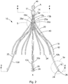
- FIG. 2 illustrates a vena cava filter 10 in accordance with the present invention.
- the filter 10 is in an expanded state and comprises four filter legs or primary struts 12a-d, each having first ends 14 that emanate from a hub 11.
- the hub 11 attaches by crimping the first ends 14 of the primary struts 12a-d together along a center point A in a compact bundle along a central or longitudinal axis X of the filter.
- the hub 11 has a minimal diameter for the size of wire used to form the primary struts 12a-d.
- the primary struts 12a-d are formed from a spring material or a superelastic material, including but not limited to stainless steel, cobalt-chromium-nickel-molybdenum-iron alloy, cobalt-chrome alloy, nitinol, or any other suitable material that will result in a self-opening or self-expanding filter.
- the primary struts 12a-d are preferably formed from wire having a round or near round cross-section with a diameter of at least about 0.381mm (0.015 inches).
- the primary struts 12a-d could take on any shape with rounded edges to maintain non-turbulent blood flow therethrough.
- each primary strut 12a-d extends from the first end 14 to a second end 15 and includes an arcuate segment 16 having a soft S-shape.
- Each arcuate segment 16 is formed with a first curved proximal portion 20 that is configured to softly bend away from the longitudinal axis X of the filter 10 and a second curved distal portion 23 that is configured to softly bend toward the longitudinal axis of the filter 10. Due to the soft bends of each arcuate segment 16, a prominence or a point of inflection on the primary strut 12a-d is substantially avoided to aid in non-traumatically engaging the vena cava or vessel wall 51. As explained in more detail below with reference to FIGS. 5 and 6 , the first curved proximal portion 20 of each primary strut 12a-d has an axial or circumferential bend 25a-d.
- each of the primary struts 12a-d is an anchor leg, including an anchoring hook 26 at the second end 15 that will anchor in the vessel wall 51 when the filter 10 is deployed at a delivery location in the blood vessel.
- the primary struts 12a-d are configured to move between the expanded state for engaging the anchoring hooks 26 with the blood vessel and the collapsed state for filter retrieval or delivery.
- each arcuate segment 16 extends arcuately along a longitudinal X (as shown in FIG. 2 ) and substantially linearly along a diametric plane (as shown in FIG. 6 ) to avoid entanglement with other primary struts 12a-d.
- each arcuate segment 16 allows each primary strut 12a-d to cross another primary strut 12a-d along the longitudinal axis X in the collapsed state such that each anchoring hook 26 faces the longitudinal axis X for filter retrieval or delivery.
- the anchoring hooks 26 at the second ends 15 of the primary struts 12a-d engage the inner wall 51 of the blood vessel 52 to define a first axial portion to secure the filter 10 in the blood vessel 52.
- the anchoring hooks 26 prevent the filter 10 from migrating from the delivery location in the blood vessel 52 where it has been deposited.
- the primary struts 12a-d are shaped and dimensioned such that, when the filter 10 is freely expanded, the filter 10 has a diameter of between about 25 mm and 45 mm and a length of between about 3 cm and 7cm.
- the filter 10 may have a diameter of about 35 mm and a length of about 5 cm.
- the primary struts 12a-d have sufficient spring strength that when the filter 10 is deployed the anchoring hooks 26 will anchor into the vessel wall 51.
- the second curved distal portion 23 of each of the primary struts 12a-d includes a stabilizer, or stop member, 24 in close proximity to the anchoring hook 26.
- the anchoring hooks 26 prevent migration of the filter 10 within the blood vessel.
- the anchoring hooks 26 accomplish this by piercing a small hole, or making a small cut, in the vessel wall 51 to penetrate the vessel wall 51.
- the stop members 24 are configured to prevent further, excessive penetration of the anchoring hook 26 through the hole or cut in the vessel wall 51.
- the stop members 24 provide enhanced visualization of the anchoring hooks 26 and their respective positions relative to the vessel wall 51.
- Each stop member 24 is disposed distally relative to the anchoring hook 26 such that the second end 15 of each primary strut 12a-d terminates with the stop member 24.
- Each stop member 24 is formed separately from each primary strut 12a-d and is attached to the second end 15 of each primary strut 12a-d at the curved portion of the anchoring hook 26. According to the invention, the stop member 24 is welded to each primary strut 12a-d, although the stop member 24 could be attached to the primary strut 12a-d by any other suitable attachment means, including but not limited to soldering or gluing.
- the length of the stop member 24 (i.e., the distance the stop member 24 extends from the anchoring hook 26) is between about 0.5 mm and about 10.0 mm.
- the diameter of the stop member 24 is preferably about the same diameter of the primary strut 12a-d, give or take about 0.2 mm.
- the distal tip 27 of the stop member 24 is rounded so that it is atraumatic to the vessel wall 51.
- each stop member 24 is configured to engage or abut the vessel wall 51 to prevent further penetration of the anchoring hooks 26.
- the stop member 24 is atraumatic and thus does not pierce the vessel wall 51. Rather, as shown in FIG. 4a , the stop member 24 pushes against the vessel wall 51, thereby preventing the anchoring hook 26 from further penetrating into the vessel wall 51. Accordingly, each stop member 24 is configured to reduce the likelihood of increased trauma to the vessel wall 51 caused by further penetration of the adjacent anchoring hook 26 into or through the vessel wall 51.
- stop members 24 provide physicians with the ability to identify placement of the anchoring hooks 26 relative to the vena cava wall 51.
- the stop members 24 are thus preferably formed from a different material than the primary struts 12a-d, most preferably a radiopaque material, such as platinum, palladium or any suitable radiopaque material known in the art.
- the stop members 24 may include a plurality of dimples 31 formed on an outer surface thereof to further enhance visualization of anchoring hook 26 placement, not only under x-ray examination, but under ultrasound examination as well.
- the dimples 31 provide the outer surface of the stop members 24 with the desired surface irregularities capable of reflecting ultrasound waves.
- the dimples 31 are small, circular indentations impressed upon the outer surface of the stop members 24 by any suitable means known in the art and have a diameter of approximately 0.1 mm and a depth of approximately 0.01 mm. They are preferably distributed over the entire outer surface of the stop members 24.
- the dimples 31 may be formed on the stop members 24 before or after attachment thereof to the primary struts 12.
- a plurality of dimples 31 to be formed on a portion of the outer surface of the primary struts 12 adjacent the anchoring hook 26, as shown in FIGS. 3a and 4a , to further enhance visualization of the filter 10 via ultrasound.
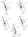
- FIGS. 3b and 4b depict an alternative embodiment of a primary strut 212 of a filter 210 not in accordance with the teachings of the present invention and having a description similar to that of FIGS. 3a and 4a , and in which similar components are denoted by similar reference numerals increased by 200.
- the stop member 224 is disposed proximally relative to the anchoring hook 226 such that the second end 215 terminates with the anchoring hook 226.
- the stop member 224 projects radially outward from the primary strut 212 to provide a portion of the primary strut 212 having an increased circumferential area.
- the stop member 224 is a conical annular band having an apex region 224a and a base 224b.
- the stop member 224 has an inner diameter sized and configured to receive the primary strut 212.
- the primary strut 212 has an outer diameter d 1
- the base 224b of the stop member 224 has an outer diameter d 2 greater than the outer diameter d 1 of the primary strut 212
- the apex region 224a of the stop member 224 has an outer diameter d 3 smaller than the outer diameter d 2 of the base 224b and slightly larger than outer diameter d 1 of the primary strut 212.
- the outer diameter of the conical annular stop member 224 tapers proximally from the base 224b to the apex region 224a.
- each stop member 224 provides a portion of each primary strut 212 with an increased circumferential area.
- the anchoring hook 226 is curved in a direction toward the hub and the stop member 224 extends in a direction away from the hub, i.e., the stop member 224 radially expands from the apex region 224a to the base 224b.
- each stop member 224 is formed separately from the primary strut 212 and is attached to the distal portion 223 of each primary strut 212 proximally relative to the anchoring hook 226.
- the annular stop member 224 may be slid over the second end 215 of the primary strut 212 prior to forming the anchoring hook 226 at the terminal end of the primary strut 212.
- the stop member 224 may be attached to the primary strut 212 by any suitable means known in the art, including but not limited to crimping, soldering, gluing, or laser welding.
- the anchoring hook 226 may be formed by curving the terminal end of the primary strut 212 in a direction toward the hub.
- the stop member 224 is disposed between about 2 mm and about 10 mm, and most preferably about 5 mm, from the anchoring hook 226.
- each primary strut 212 is configured to prevent further penetration of the anchoring hooks 226 into the vessel wall 51.
- the increased circumferential area of the primary strut 212 i.e., the stop member 224, is configured to engage or abut the vessel wall 51 to prevent further penetration of the anchoring hooks 226.
- the stop member 224 is configured to reduce the likelihood of increased trauma to the vessel wall 51 caused by further penetration of the anchoring hook 226 into the vessel wall 51.
- FIGS. 3c and 4c depict an alternative embodiment of a primary strut 312 of a filter 310 not in accordance with the teachings of the present invention and having a description similar to that of FIGS. 3a and 4a , and in which similar components are denoted by similar reference numerals increased by 300.
- the stop member 324 is disposed proximally relative to the anchoring hook 326 such that the second end 315 terminates with the anchoring hook 326.
- the stop member 324 projects radially outward from the primary strut 312 to provide a portion of the primary strut 312 with an increased circumferential area. As shown in FIGS.
- the stop member 324 is an annular band having a cylindrical ring portion 329 and a barb extension 328 formed unitarily therewith.
- the stop member 324 has an inner diameter sized and configured to receive the primary strut 312 and the barb extension 328 extends radially from the primary strut 312 in a direction away from the longitudinal axis X when the filter 310 is in the expanded state.
- the primary strut 312 has an outer diameter d 1 and the barb extension 328 extending radially from the primary strut 312 defines an outer diameter d 4 greater than the outer diameter d 1 .
- the stop member 324 includes a barb extension 328, which defines an increased outer diameter d 4 , and thus provides a portion of each primary strut 312 with an increased circumferential area.
- the anchoring hook 326 is curved in a direction toward the hub and the barb extension 328 extends in a direction away from the hub.
- each stop member 324 is preferably formed separately from the primary strut 312 and is attached to the distal portion 323 of each primary strut 312 proximally relative to the anchoring hook 326.
- the annular stop member 324 may be slid over the second end 315 of the primary strut 312 prior to forming the anchoring hook 326 at the terminal end of the primary strut 312.
- the stop member 324 may be attached to the primary strut 312 by any suitable means known in the art, including but not limited to crimping, soldering, gluing, or laser welding.
- the anchoring hook 326 may be formed by curving the terminal end of the primary strut 312 in a direction toward the hub.
- the stop member 324 is disposed between about 2 mm and about 10 mm, and most preferably about 5 mm, from the anchoring hook 326.
- each primary strut 312 is configured to prevent further penetration of the anchoring hooks 326 into the vessel wall.
- the increased circumferential area of the primary strut 312, i.e., the stop member 324 is configured to engage or abut the vessel wall 51 to prevent further penetration of the anchoring hooks 326.
- the barb extension 328 of the stop member 324 pushes against the vessel wall 51, thereby preventing the anchoring hook 326 from further penetrating into the vessel wall 51. Accordingly, the stop member 324 is configured to reduce the likelihood of increased trauma to the vessel wall 51 caused by further penetration of the anchoring hook 326 into the vessel wall 51.
- the barb extension 328 preferably has a sharpened tip which engages or anchors into the vessel wall 51 to prevent further penetration of the anchoring hook 326.
- the sharpened tip functions as an additional hooking member.
- the sharpened tip of the barb extension 328 is able to pierce the wall, thus providing a higher resistance against the vessel wall 51 to prevent the strut 312 from penetrating further.
- FIGS. 3d and 4d depict an alternative embodiment of a primary strut 412 of a filter 410 not in accordance with the teachings of the present invention and having a description similar to that of FIGS. 3a and 4a , and in which similar components are denoted by similar reference numerals increased by 400.
- the stop member 424 is disposed proximally relative to the anchoring hook 426 such that the second end 415 terminates with the anchoring hook 426.
- the stop member 424 projects radially outward from the primary strut 412 to provide a portion of the primary strut 412 with an increased circumferential area. As shown in FIGS.
- the stop member 424 is a bent or curved wire filament having a tangential portion 431 tangential to and attached to the primary strut 412 and a projecting portion 433 projecting radially outward from the primary strut 412, i.e., in a direction away from the longitudinal axis X, when the filter 410 is in the expanded state.
- the primary strut 412 has an outer diameter d 1 and the projecting portion 433 of the stop member 424 extending radially from the primary strut 412 defines an outer diameter d 5 greater than the outer diameter d 1 .
- the projecting portion 433 is bent at an angle of about 45 degrees with respect to an axis defined by the distal portion 423 of the primary strut 412, as illustrated in FIG. 3d .
- the difference between d 5 and d 1 is preferably about 1 mm, i.e., the projecting portion 433 projects about 1 mm from the primary strut 412.
- the stop member 424 defines an increased outer diameter d 5 , and thus provides a portion of each primary strut 412 with an increased circumferential area.
- the anchoring hook 426 is curved in a direction toward the hub and the projecting portion 433 of the stop member 424 extends in a direction away from the hub.
- each stop member 424 is formed separately from the primary strut 412 and is attached to the distal portion 423 of each primary strut 412 proximally relative to the anchoring hook 426.
- the tangential portion 431 of the stop member 424 is attached to the primary strut 412 by any suitable means known in the art, including but not limited to crimping, soldering, gluing, or laser welding.
- the stop member 424 is disposed between about 2 mm and about 10 mm, and most preferably about 5 mm, from the anchoring hook 426.
- the opposite orientation of the anchoring hook 426 and corresponding projecting portion 433 of the stop member 424 of each primary strut 412 is configured to prevent further penetration of the anchoring hooks 426 into the vessel wall.
- the increased circumferential area of the primary strut 412, i.e., the stop member 424, is configured to engage or abut the vessel wall 51 to prevent further penetration of the anchoring hooks 426.
- the stop member 424 is configured to reduce the likelihood of increased trauma to the vessel wall 51 caused by further penetration of the anchoring hook 426 into the vessel wall 51.
- the projecting portion 433 may have a sharpened tip which engages or anchors into the vessel wall 51 to prevent further penetration of the anchoring hook 426.
- the sharpened tip functions as an additional hooking member.
- the sharpened tip of the projecting portion 433 is able to pierce the wall, thus providing a higher resistance against the vessel wall 51 to prevent the strut 412 from penetrating further.
- FIGS. 3e and 4e depict an alternative embodiment of a primary strut 512 of a filter 510 not in accordance with the teachings of the present invention and having a description similar to that of FIGS. 3a and 4a , and in which similar components are denoted by similar reference numerals increased by 500.
- the stop member 524 is disposed proximally relative to the anchoring hook 526 such that the second end 515 terminates with the anchoring hook 526.
- the stop member 524 projects radially inward from the primary strut 512, as opposed to projecting radially outward in the embodiment of FIGS. 3d and 4d , to provide a portion of the primary strut 512 with an increased circumferential area. As shown in FIGS.
- the stop member 524 is a bent or curved wire filament having a tangential portion 531 tangential to and attached to the primary strut 512 and a projecting portion 533 projecting radially inward from the primary strut 412, i.e., in a direction toward the longitudinal axis X, when the filter 510 is in the expanded state.
- the primary strut 512 has an outer diameter d 1 and the projecting portion 533 of the stop member 524 extending radially from the primary strut 512 defines an outer diameter d 6 greater than the outer diameter d 1 .
- the projecting portion 533 is bent at an angle of about 45 degrees with respect to an axis defined by the distal portion 523 of the primary strut 512, as illustrated in FIG. 3e .
- the difference between d 6 and d 1 is preferably about 1 mm, i.e., the projecting portion 533 projects about 1 mm from the primary strut 512.
- the stop member 524 defines an increased outer diameter d 6 , and thus provides a portion of each primary strut 512 with an increased circumferential area.
- the anchoring hook 526 is curved in a direction toward the hub and the projecting portion 533 of the stop member 524 extends in a direction away from the hub.
- each stop member 524 is formed separately from the primary strut 512 and is attached to the distal portion 523 of each primary strut 512 proximally relative to the anchoring hook 526.
- the tangential portion 531 of the stop member 524 is attached to the primary strut 512 by any suitable means known in the art, including but not limited to crimping, soldering, gluing, or laser welding.
- the stop member 524 is disposed between about 2 mm and about 10 mm, and most preferably about 5 mm, from the anchoring hook 526.
- the opposite orientation of the anchoring hook 526 and corresponding projecting portion 533 of the stop member 524 of each primary strut 512 is configured to prevent further penetration of the anchoring hooks 526 into the vessel wall.
- the increased circumferential area of the primary strut 512, i.e., the stop member 524, is configured to engage or abut the vessel wall 51 to prevent further penetration of the anchoring hooks 526.
- the backside of the projecting portion 533 of the stop member 524 pushes against the vessel wall 51, thereby preventing the anchoring hook 526 from further penetrating into the vessel wall 51.
- the backside of the projecting portion 533 is substantially tangent to the vessel wall 51, i.e., substantially the entire length l of the projecting portion 533 abuts the vessel wall 51, providing a larger contact area configured to engage the vessel wall 51, and thus a higher resistance to prevent further penetration by the anchoring hooks 526.
- the stop member 524 is configured to reduce the likelihood of increased trauma to the vessel wall 51 caused by further penetration of the anchoring hook 526 into the vessel wall 51.
- stop members of FIGS. 3b-e are preferably a radiopaque material and formed separately from respective primary struts
- the stop members 424, 524 in FIGS. 3d and 3e may be formed integrally, i.e., unitarily, with respective primary struts 412, 512 by laser cutting a series of slits in the primary struts 412, 512 and bending the portion of the primary struts 412, 512 defined by the slits to resemble the projecting portion 433, 533 of the separate wire filament stop member 424, 524 discussed above.
- anchoring hooks and stop members shown and described with respect to FIGS. 3a-e may be incorporated with alternative filter designs, including but not limited to the filter described in U.S. Patent No. 5,133,733 to Rasmussen et al .
- each primary strut 12a-d preferably includes a distal bend 43 formed thereon and extending outwardly radially from the longitudinal axis X.
- the distal bend 43 may extend outwardly at an angle ⁇ between about 0.5 degree and 2 degrees, preferably 1 degree.
- the distal bend 43 may be situated at a distance from the anchoring hook 26, which is arranged at the end of a substantially straight strut segment.
- the distal bend 43 may have a length of between about 1 and 7 mm, preferably between about 2 and 4 mm. The distal bend 43 allows the filter 10 to filter thrombi effectively at a smaller inside diameter of a blood vessel than otherwise would be possible while maintaining the ability to collapse for delivery or retrieval.
- the distal bend 43 provides for a more firm engagement of the anchoring hook 26 at the vessel wall.
- the primary struts 12a-d will urge the vessel wall outwards, whereas the vessel wall will urge the primary struts 12a-d inwards toward the longitudinal axis X of the filter 10.
- the anchoring hooks 26 are angled by between about 50 and 80 degrees with respect to the last segment of the primary strut 12a-d, preferably between about 50 and 60 degrees.
- each primary strut 12a-d includes a respective axial bend 25a-d.
- each primary strut 12a-d includes a first end 14 which emanates from within the hub 11 and a section 13a-d which extends linearly along a diametric plane between the first end 14 and the axial bend 25a-d.
- the axial bends 25a-d of the respective primary struts 12a-d result in each primary strut 12a-d being angled by an angle ⁇ from a plane defined by the longitudinal axis X and a point along the section 13a-d of that particular primary strut 12a-d.
- the axial bend 25a of the primary strut 12a is angled from the plane P by an angle ⁇ .
- the plane P is defined by the longitudinal axis X and a point along the section 13a that extends between the first end 14 of the primary strut 12a and the axial bend 25a.
- Each proximal portion 20 of each primary strut 12a-d has an axial bend 25a-d formed thereon relative to the longitudinal axis X of the filter 10 and the first end 14, or any point along the section 13a-d, of the respective primary strut 12a-d such that the primary struts 12a-d maintain continuous consistent orientation together when moving between the opened and closed configurations.
- the primary struts 12a-d maintain a relatively uniform or relatively symmetrical arrangement relative to an end view of the filter.
- the axial bends 25a-d cause the primary struts 12a-d to close and open relatively consistently, lessening the chance of entanglement. For example (see end view in FIG. 6 ), the relative arrangement of the primary struts 12a-d is maintained, avoiding crossing over of primary struts 12a-d and thus lessening entanglement thereof.
- the primary struts 12a-d extend substantially linearly along a diametric plane.
- the axial bend 25a-d on the first curved proximal portion 20 of each primary strut 12a-d results in each primary strut 12a-d extending linearly along a diametric plane from the first end 14 to just before the axial bend 25a-d and from just after the axial bend 25a-d to the second end 15.
- the term “substantially linearly,” as opposed to merely “linearly,” takes into account this slight axial bend 25a-d on each of the respective primary struts 12a-d.
- a pair of opposed primary struts may be offset by bending the struts 12a and 12c by between about 0.5 degree and 2 degrees relative to plane P to allow the pair of struts 12a and 12c to cross each other relative to the longitudinal axis X.
- the opposed first ends 14 and sections 13a and 13c of respective primary struts 12a and 12c are arranged parallel to one another.
- the axial bends 25a, 25c are angled with respect to the same plane, plane P, defined by the longitudinal axis X and a point along the section 13a of primary strut 12a and a point along the section 13c of the primary strut 12c.
- the pair of opposed primary struts 12b and 12d As illustrated in FIGS. 5 and 6 , the opposed primary struts 12b and 12d are arranged parallel to one another. Accordingly, the axial bends 25b. 25d are angled with respect to the same plane, plane P', defined by the longitudinal axis X and a point along the section 13b of the primary strut 12b and a point along the section 13d of the primary strut 12d. By the offset, the portion of each primary strut 12a-d extending between the respective axial bend 25a-d and the second end of the strut 12a-d is substantially parallel to the corresponding portion of the opposed primary strut 12a-d.
- the axial bends 25a-d cause the primary struts 12a-d to be consistently oriented together relative to the longitudinal axis X in each occasion the filter 10 is collapsed in the closed state.
- the struts 12a-d expand consistently radially outwardly and remain in relatively the same orientation or arrangement together. As a result, the risk of entanglement of the struts is reduced.
- each axial bend 25a-d may range between about 0.5 and 5°.
- the second curved distal portions 23 move consistently radially, in a rotating fashion, from the longitudinal axis X toward the vessel wall. The rotating radial movement of the second curved distal portions 23 aid in reducing the risk of entanglement of the primary struts 12a-d,
- the filter 10 includes a plurality of secondary struts 30 having connected ends 32 attached that also emanate from hub 1 1.
- Hub 1 1 attaches by crimping the connected ends 32, along the center point A, of the secondary struts 30 together with the primary struts 12a-d.
- each primary strut 12a-d has two secondary struts 30 in side-by-side relationship with the primary strut 12a-d.
- the secondary struts 30 extend from the connected ends 32 to free ends 34 to centralize the filter 10 in the expanded state in the blood vessel.
- the secondary struts 30 terminate with the free end 34 and without an anchoring hook or a stop member.
- each secondary strut 30 extends arcuately along a longitudinal plane and linearly along a diametric plane (see end view in FIG. 6 ) from the connected end 32 to the free end 34, i.e., the secondary struts 30 do not extend helically.
- the secondary struts 30 may be made from the same type of material as the primary struts 12a-d. However, the secondary struts 30 may have a smaller diameter, e.g., at least about 0.305mm (0.012 inches), than the primary struts 12a-d.
- each of the secondary struts 30 is formed of a first arc 40 and a second arc 42. As shown in FIG. 2 , the first arc 40 extends from the connected end 32 away from the longitudinal axis X and the second arc 42 extends from the first arc 40 towards the longitudinal axis X.
- two secondary struts 30 are located on each side of one primary strut 12a-d to form a part of a netting configuration of the filter 10.
- the hub 11 is preferably made of the same material as the primary struts and secondary struts to minimize the possibility of galvanic corrosion or molecular changes in the material due to welding.
- FIG. 6 illustrates the netting pattern including primary struts 12a-d and secondary struts 30 independently spaced substantially equally at their respective planes.
- the secondary struts 30 may be spaced equally relative to the other secondary struts 30 and the primary struts 12a-d may be spaced equally relative to the other primary struts 12a-d.
- the netting pattern in this embodiment shown by the end view of the filter 10 in FIG. 2 (taken along line 6-6) will have uneven or unequal spacing between the primary struts 12a-d and secondary struts 30.
- the primary and secondary struts 12a-d and 30 may be arranged in any other suitable manner as desired.
- free ends 34 of the secondary struts 30 When freely expanded, free ends 34 of the secondary struts 30 will expand radially outwardly to a diameter of about 25 mm to 45 mm.
- the secondary struts 30 may expand radially outwardly to a diameter of between about 35 mm and 45 mm.
- the second arcs 42 of the free ends 34 engage the wall 51 of a blood vessel 52 to define a second axial plane where the vessel wall 51 is engaged.
- the secondary struts 30 function to stabilize the position of the filter 10 about the center of the blood vessel 52 in which it is deployed.
- the filter 10 has two layers or planes of struts longitudinally engaging the vessel wall 51 of the blood vessel 52.
- the length of the filter 10 is preferably defined by the length of a primary strut 12a-d.
- the diameter of the hub 11 is defined by the size of a bundle containing the primary struts 12a-d and secondary struts 30.
- the eight secondary struts 30 minimally add to the diameter of the hub 1 1 or the overall length of the filter 10, due to the reduced diameter of each secondary strut 30. This is accomplished while maintaining the filter 10 in a centered attitude relative to the vessel wall 51 and formed as a part of the netting configuration of the filter 10.
- removal hook 46 extends from hub 1 1 opposite primary and secondary struts 12a-d and 30.
- each arcuate segment 16 has a thickness of at least about 0.381mm (0.015 inch) and a tensile strength of between about 1,965,006kPA (285,000 pounds per square inch (psi)) and 2,275,270kPA (330,000 psi).
- Each anchoring hook 26 is integral with the arcuate segment 16 and has the thickness and the tensile strength of the arcuate segment.
- Each secondary strut 30 has a thickness of at least about 0.305mm (0.012) inch and a tensile strength of between about 1,965,006kPA and 2,275,270kPA (285,000 psi and 330,000 psi).
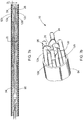
- FIG. 7a illustrates the filter 10 in a collapsed state disposed in a delivery/retrieval tube or sheath 94 for delivery or retrieval.
- the filter 10 has primary struts 12a-d, each of which is formed with an axial bend 25a-d for consistent orientation and shaped to cooperate with another primary strut 12a-d along the longitudinal axis X.
- the anchoring hooks 26 are configured to be inverted or be inwardly positioned along the longitudinal axis X away from the inner wall 95 of the delivery/retrieval sheath 94 and the blood vessel walls for retrieval/delivery of the filter 10.
- This inverted or inwardly facing configuration of the anchoring hooks 26 allows for simplified delivery and retrieval of filter 10
- a concern that the anchoring hooks 26 in the collapsed state may scrape, scratch, or tear the inner wall of a delivery/retrieval tube is eliminated, since the filter 10 of the present invention is shaped to have the anchoring hooks 26 inwardly face each other in the collapsed state.
- a set of inner and outer delivery/retrieval sheaths may be eliminated during the delivery or retrieval of the filter 10 through the jugular or femoral vein. Rather, merely one delivery/retrieval tube with a loop snare mechanism may be used to retrieve the filter 10 of the present invention.
- the anchoring hooks 226, 326, and 426 are oriented opposite of the respective stop members 224, 324, and 424 such that the anchoring hooks 226, 326, and 426 are curved in a direction toward the hub 1 1 and toward the respective stop members 224, 324, and 424, and the stop members 224 324 and 424 extend in a direction away from the hub 1 1 and toward the respective anchoring hooks 226, 326, and 426.
- the barb extension 328 of the stop member 324 in FIG. 3c and the projecting portion 433 of the stop member 424 in FIG. 3d are configured to be inverted or be inwardly positioned along the longitudinal axis X away from the inner wall 95 of the delivery/retrieval sheath 94 and the blood vessel walls for retrieval/delivery of the respective filters 310 and 410.
- each primary strut 12a-d is configured to cooperate with another primary strut 12a-d along the longitudinal axis X such that the arcuate segments 16, first curved proximal portions 20 or second curved distal portions 23, occupy a first diameter D1.
- the first diameter is greater than a second diameter D 2 occupied by the anchoring hooks 26 for filter retrieval or delivery. It has been found that the first diameter of the arcuate segments 16 serves to clear a path of retrieval, reducing radial force from the sheath or blood vessel on the anchoring hooks 26 during removal of the filter 10 from a patient. Reducing the radial force on the anchoring hooks 26 assists in preventing the anchoring hooks 26 from scraping, scratching, or tearing the inner wall of a sheath during removal of the filter 10 from a patient.
- the filter 10 may be delivered or retrieved by any suitable introducer (delivery or retrieval) sheath.
- the introducer sheath has an inside diameter of between about 4.5 French and 16 French, and more preferably between about 6.5 French and 14 French.
- FIG. 8 illustrates a cross-sectional view of the filter 10 of FIG. 2 at hub 11.
- the hub 11 houses a bundle of first ends 14 of the four primary struts 12a-d and connected ends 32 of secondary struts 30.
- FIG. 8 further depicts the configurations of the primary and secondary struts 12a-d and 30.
- the primary struts 12a-d are spaced between two secondary struts 30.
- the primary struts 12a-d may be spaced between any other suitably desired number of secondary struts 30 without falling beyond the scope or spirit of the present invention.
- FIG. 9 illustrates the filter 10 fully expanded after being deployed in a blood vessel, for example, the inferior vena cava 52.
- the inferior vena cava 52 has been broken away so that the filter 10 can be seen.
- the direction of the blood flow BF is indicated in FIG. 9 , by the arrow that is labeled BF.
- the anchoring hooks 26 at the ends of the primary struts 12a-d are shown as being anchored in the inner lining of the inferior vena cava 52.
- the anchoring hooks 26 include barbs 29 that, in one embodiment, project toward the hub 11 of the filter. The barbs 29 function to retain the filter 10 in the location of deployment.
- the spring biased configuration of the primary struts 12a-d further causes the anchoring hooks 26 to engage the vessel wall and anchor the filter at the location of deployment. After initial deployment, the pressure of the blood flow on the filter 10 contributes in maintaining the barbs 29 anchored in the inner lining of the inferior vena cava 52. As seen in FIG. 9 , the second arcs 42 of secondary struts 30 also have a spring biased configuration to engage with the vessel wall.
- the hub 11 and removal hook 46 are positioned downstream from the location at which the anchoring hooks 26 are anchored in the vessel.
- thrombi remains lodged in the filter.
- the filter 10 along with the thrombi may then be percutaneously removed from the vena cava.
- the removal hook 46 is preferably grasped by a retrieval instrument that is percutaneously introduced in the vena cava in the direction of removal hook 16 first.
- the primary struts may be overgrown by neovascular overgrowth of the intima layer of the vessel wall.
- the tendency of overgrowing of the struts is increased by the spring biased configuration of the struts and the radial outward orientation of the outer end of the struts in relation to the longitudinal axis. This results in the struts dilating the vessel wall along the contact surface of the struts with the vessel wall.
- the intima layer overgrowing the struts will increase the anchoring of the filter, so the struts will follow the movements of the wall, and migration of the filter is avoided.
- the filter may be removed without any substantial damage to the vessel wall.
- the intima layer that has overgrown the struts will restrict the pulling forces to act parallel to the wall and thereby pulling the struts out easily, instead of breaking the overgrown layer.
- Apart from a small cut caused by the hook there will not be any further damage and the cut will heal in relatively less time whereas tearing of the intima layer would otherwise take relatively more time to heal.
- the filter 10 may be comprised of any suitable material such as superelastic material or spring material, including but not limited to nitinol, stainless steel wire, cobalt-chromium-nickel-molybdenum-iron alloy, or cobalt-chrome alloy. It is understood that the filter 10 may be formed of any other suitable material that will result in a self-opening or self-expanding filter, such as shape memory alloys. Shape memory alloys have a property of becoming rigid, i.e., returning to a remembered state, when heated above a transition temperature.
- a shape memory alloy suitable for the present invention may comprise Ni-Ti available under the more commonly known name Nitinol.
- transition temperature is dependent on the relative proportions of the alloying elements Ni and Ti and the optional inclusion of alloying additives.
- the filter 10 may be made from Nitinol with a transition temperature that is slightly befow normal body temperature of humans, which is about 37°C (98.6°F).
- the alloy of the filter 10 when the filter 10 is deployed in a body vessel and exposed to normal body temperature, the alloy of the filter 10 will transform to austenite, that is, the remembered state, which for one embodiment of the present invention is the expanded configuration when the filter 10 is deployed in the body vessel.
- the filter 10 is cooled to transform the material to martensite which is more ductile than austenite, making the filter 10 more malleable. As such, the filter 10 can be more easily collapsed and pulled into a lumen of a catheter for removal.
- the filter 10 may be made from Nitinol with a transition temperature that is above normal body temperature of humans, which is about 37°C (98.6°F).
- a transition temperature that is above normal body temperature of humans, which is about 37°C (98.6°F).
- the filter 10 when the filter 10 is deployed in a body vessel and exposed to normal body temperature, the filter 10 is in the martensitic state so that the filter 10 is sufficiently ductile to bend or form into a desired shape, which for the present invention is an expanded configuration.
- the filter 10 is heated to transform the alloy to austenite so that the filter 10 becomes rigid and returns to a remembered state, which for the filter 10 in a collapsed configuration.
Claims (11)
- Filtre (10) pour capturer des thrombi dans un vaisseau sanguin (52), le filtre comprenant : une pluralité d'entretoises (12a, 12b, 12c, 12d) ayant un état replié pour la récupération ou l'implantation du filtre et un état déployé pour l'engagement avec une paroi de vaisseau (51) du vaisseau sanguin, chaque entretoise, dans l'état déployé, s'étendant depuis une première extrémité (14) jusqu'à une deuxième extrémité (15), les premières extrémités étant attachées ensemble le long d'un axe longitudinal (L) du filtre, ladite pluralité d'entretoises comprenant une pluralité d'entretoises primaires, chaque entretoise primaire s'étendant sous forme arquée le long de l'axe longitudinal et comportant une portion proximale (20) s'étendant depuis la première extrémité et une portion distale s'étendant depuis la portion proximale jusqu'à la deuxième extrémité, la portion distale de chaque entretoise comportant un crochet d'ancrage (26) configuré pour pénétrer à travers la paroi du vaisseau et un organe de butée (24) configuré pour venir en prise avec la paroi du vaisseau de manière à empêcher une pénétration supplémentaire du crochet d'ancrage dans la paroi du vaisseau, l'organe de butée étant formé d'un matériau radio-opaque pour améliorer la visualisation du crochet d'ancrage et sa position par rapport à la paroi du vaisseau, l'organe de butée (24) étant formé séparément de l'entretoise (12a, 12b, 12c, 12d) et étant soudé à l'entretoise à côté du crochet d'ancrage (26) de telle sorte que l'organe de butée s'étende distalement depuis le crochet d'ancrage, chaque deuxième extrémité d'entretoise (15) se terminant avec l'organe de butée (24).
- Filtre (10) selon la revendication 1, dans lequel l'organe de butée (24) est formé de l'un parmi : (i) du platine et (ii) du palladium.
- Filtre selon la revendication 1 ou 2, dans lequel l'organe de butée (24) s'étend dans la direction distale depuis le crochet d'ancrage (26) sur une distance dans une plage d'environ 0,5 mm à environ 10,0 mm.
- Filtre selon l'une quelconque des revendications précédentes, dans lequel chaque entretoise primaire s'étend substantiellement linéairement le long d'un plan diamétral.
- Filtre selon l'une quelconque des revendications précédentes, dans lequel chaque entretoise primaire ne s'étend pas suivant une forme hélicoïdale.
- Filtre selon l'une quelconque des revendications précédentes, dans lequel le crochet d'ancrage de chaque entretoise est courbé dans une direction vers la première extrémité de l'entretoise en question et dans lequel l'organe de butée est soudé à l'entretoise au niveau de la portion courbe du crochet d'ancrage.
- Filtre selon l'une quelconque des revendications précédentes, dans lequel ladite pluralité d'entretoises comprend en outre une pluralité d'entretoises secondaires qui, dans l'état déployé, centralisent le filtre dans le vaisseau sanguin ; et dans lequel chaque entretoise secondaire se termine sans crochet d'ancrage ou organe de butée.
- Filtre selon la revendication 7, dans lequel chaque entretoise secondaire s'étend sous forme arquée le long d'un plan longitudinal et linéairement le long d'un plan diamétral.
- Filtre selon l'une quelconque des revendications précédentes, dans lequel la portion distale de chaque entretoise primaire comporte une courbure distale formée sur celle-ci, qui s'étend vers l'extérieur radialement depuis l'axe longitudinal.
- Filtre selon la revendication 9, dans lequel chaque courbure distale est située à une distance du crochet d'ancrage correspondant qui est agencé à l'extrémité d'un segment d'entretoise sensiblement droit.
- Filtre selon l'une quelconque des revendications précédentes, dans lequel chaque crochet d'ancrage est incliné d'environ 50 à 80 degrés par rapport au dernier segment de l'entretoise primaire correspondante, de préférence d'environ 50 à 60 degrés.
Applications Claiming Priority (2)
| Application Number | Priority Date | Filing Date | Title |
|---|---|---|---|
| US29426910P | 2010-01-12 | 2010-01-12 | |
| PCT/US2011/020950 WO2011088090A1 (fr) | 2010-01-12 | 2011-01-12 | Stabilisateur visuel sur les pieds d'ancrage de filtre de veine cave |
Publications (2)
| Publication Number | Publication Date |
|---|---|
| EP2523629A1 EP2523629A1 (fr) | 2012-11-21 |
| EP2523629B1 true EP2523629B1 (fr) | 2021-04-14 |
Family
ID=43798262
Family Applications (1)
| Application Number | Title | Priority Date | Filing Date |
|---|---|---|---|
| EP11701709.5A Active EP2523629B1 (fr) | 2010-01-12 | 2011-01-12 | Stabilisateur visuel sur les pieds d'ancrage de filtre de veine cave |
Country Status (3)
| Country | Link |
|---|---|
| US (3) | US9308066B2 (fr) |
| EP (1) | EP2523629B1 (fr) |
| WO (1) | WO2011088090A1 (fr) |
Families Citing this family (8)
| Publication number | Priority date | Publication date | Assignee | Title |
|---|---|---|---|---|
| US8702747B2 (en) * | 2011-10-21 | 2014-04-22 | Cook Medical Technologies Llc | Femoral removal vena cava filter |
| US10004512B2 (en) * | 2014-01-29 | 2018-06-26 | Cook Biotech Incorporated | Occlusion device and method of use thereof |
| GB2527761A (en) * | 2014-06-30 | 2016-01-06 | Cook Medical Technologies Llc | Improved vascular filter and anchoring arrangement therefor |
| US10117736B2 (en) | 2014-08-06 | 2018-11-06 | Cook Medical Technologies Llc | Low radial force filter |
| US20180235741A1 (en) | 2017-02-22 | 2018-08-23 | Cook Medical Technologies Llc | Conical vein filter with improved balance |
| CN107374778A (zh) * | 2017-09-12 | 2017-11-24 | 浙江归创医疗器械有限公司 | 腔静脉滤器及其回收装置 |
| US11058411B2 (en) * | 2019-01-14 | 2021-07-13 | Valfix Medical Ltd. | Anchors and locks for percutaneous valve implants |
| CN115607330B (zh) * | 2022-12-16 | 2023-03-21 | 北京心祐医疗科技有限公司 | 腔静脉滤器 |
Citations (2)
| Publication number | Priority date | Publication date | Assignee | Title |
|---|---|---|---|---|
| US20040158274A1 (en) * | 2003-02-11 | 2004-08-12 | Scimed Life Systems, Inc. | Retrievable IVC filter |
| WO2006124405A2 (fr) * | 2005-05-12 | 2006-11-23 | C.R. Bard Inc. | Filtre amovible pour caillot sanguin ou embole |
Family Cites Families (38)
| Publication number | Priority date | Publication date | Assignee | Title |
|---|---|---|---|---|
| US5059205A (en) * | 1989-09-07 | 1991-10-22 | Boston Scientific Corporation | Percutaneous anti-migration vena cava filter |
| US5242462A (en) * | 1989-09-07 | 1993-09-07 | Boston Scientific Corp. | Percutaneous anti-migration vena cava filter |
| GB2238485B (en) | 1989-11-28 | 1993-07-14 | Cook William Europ | A collapsible filter for introduction in a blood vessel of a patient |
| US5601595A (en) * | 1994-10-25 | 1997-02-11 | Scimed Life Systems, Inc. | Remobable thrombus filter |
| US7314477B1 (en) * | 1998-09-25 | 2008-01-01 | C.R. Bard Inc. | Removable embolus blood clot filter and filter delivery unit |
| US6007558A (en) * | 1998-09-25 | 1999-12-28 | Nitinol Medical Technologies, Inc. | Removable embolus blood clot filter |
| US6231589B1 (en) * | 1999-03-22 | 2001-05-15 | Microvena Corporation | Body vessel filter |
| US6267776B1 (en) * | 1999-05-03 | 2001-07-31 | O'connell Paul T. | Vena cava filter and method for treating pulmonary embolism |
| US6217600B1 (en) * | 2000-01-26 | 2001-04-17 | Scimed Life Systems, Inc. | Thrombus filter with break-away anchor members |
| US6342063B1 (en) * | 2000-01-26 | 2002-01-29 | Scimed Life Systems, Inc. | Device and method for selectively removing a thrombus filter |
| US6540767B1 (en) * | 2000-02-08 | 2003-04-01 | Scimed Life Systems, Inc. | Recoilable thrombosis filtering device and method |
| WO2003075793A1 (fr) * | 2002-03-06 | 2003-09-18 | Boston Scientific Limited | Dispositif medical de retrait |
| US8361103B2 (en) * | 2003-02-07 | 2013-01-29 | Karla Weaver | Low profile IVC filter |
| US7763045B2 (en) * | 2003-02-11 | 2010-07-27 | Cook Incorporated | Removable vena cava filter |
| US20040186510A1 (en) * | 2003-03-18 | 2004-09-23 | Scimed Life Systems, Inc. | Embolic protection ivc filter |
| US20050055045A1 (en) * | 2003-09-10 | 2005-03-10 | Scimed Life Systems, Inc. | Composite medical devices |
| US6972025B2 (en) * | 2003-11-18 | 2005-12-06 | Scimed Life Systems, Inc. | Intravascular filter with bioabsorbable centering element |
| US8231649B2 (en) * | 2004-01-20 | 2012-07-31 | Boston Scientific Scimed, Inc. | Retrievable blood clot filter with retractable anchoring members |
| US7976562B2 (en) * | 2004-01-22 | 2011-07-12 | Rex Medical, L.P. | Method of removing a vein filter |
| US8500774B2 (en) * | 2004-01-22 | 2013-08-06 | Rex Medical, L.P. | Vein filter |
| US8062326B2 (en) * | 2004-01-22 | 2011-11-22 | Rex Medical, L.P. | Vein filter |
| AU2005234753B2 (en) * | 2004-04-16 | 2010-12-02 | Cook, Inc. | Removable vena cava filter having inwardly positioned anchoring hooks in collapsed configuration |
| EP1737385B1 (fr) * | 2004-04-16 | 2010-12-15 | Cook Incorporated | Filtre de veine cave amovible comprenant un element de fixation pour lesion reduite |
| AU2005234752B2 (en) * | 2004-04-16 | 2010-12-16 | Cook, Inc. | Removable vena cava filter having primary struts for enhanced retrieval and delivery |
| US7625390B2 (en) * | 2004-04-16 | 2009-12-01 | Cook Incorporated | Removable vena cava filter |
| US7699867B2 (en) * | 2004-04-16 | 2010-04-20 | Cook Incorporated | Removable vena cava filter for reduced trauma in collapsed configuration |
| US7544202B2 (en) * | 2004-06-25 | 2009-06-09 | Angiodynamics, Inc. | Retrievable blood clot filter |
| US20060015137A1 (en) * | 2004-07-19 | 2006-01-19 | Wasdyke Joel M | Retrievable intravascular filter with bendable anchoring members |
| US7704267B2 (en) * | 2004-08-04 | 2010-04-27 | C. R. Bard, Inc. | Non-entangling vena cava filter |
| ATE545385T1 (de) * | 2004-09-20 | 2012-03-15 | Cook Medical Technologies Llc | Antithrombus-filter mit verbesserten identifikationsmerkmalen |
| CN101031254B (zh) * | 2004-09-27 | 2010-10-27 | 库克公司 | 包括具有轴向弯曲部的支杆的可移除腔静脉过滤器 |
| US7959645B2 (en) * | 2004-11-03 | 2011-06-14 | Boston Scientific Scimed, Inc. | Retrievable vena cava filter |
| CA2586641A1 (fr) * | 2004-11-08 | 2006-05-18 | Cook, Inc. | Filtre de caillot sanguin concu pour un fil-guide |
| US9107733B2 (en) * | 2006-01-13 | 2015-08-18 | W. L. Gore & Associates, Inc. | Removable blood conduit filter |
| US8795351B2 (en) * | 2007-04-13 | 2014-08-05 | C.R. Bard, Inc. | Migration resistant embolic filter |
| US20110202086A1 (en) * | 2008-08-29 | 2011-08-18 | Bates Brian L | Vena cava filter having plurality of hooks |
| US8246648B2 (en) * | 2008-11-10 | 2012-08-21 | Cook Medical Technologies Llc | Removable vena cava filter with improved leg |
| CA2769208C (fr) * | 2009-07-29 | 2017-10-31 | C.R. Bard, Inc. | Filtre tubulaire |
-
2011
- 2011-01-12 EP EP11701709.5A patent/EP2523629B1/fr active Active
- 2011-01-12 WO PCT/US2011/020950 patent/WO2011088090A1/fr active Application Filing
- 2011-01-12 US US13/521,458 patent/US9308066B2/en active Active
-
2015
- 2015-11-19 US US14/945,725 patent/US9592107B2/en active Active
-
2017
- 2017-01-26 US US15/416,096 patent/US10258454B2/en active Active
Patent Citations (2)
| Publication number | Priority date | Publication date | Assignee | Title |
|---|---|---|---|---|
| US20040158274A1 (en) * | 2003-02-11 | 2004-08-12 | Scimed Life Systems, Inc. | Retrievable IVC filter |
| WO2006124405A2 (fr) * | 2005-05-12 | 2006-11-23 | C.R. Bard Inc. | Filtre amovible pour caillot sanguin ou embole |
Also Published As
| Publication number | Publication date |
|---|---|
| US9592107B2 (en) | 2017-03-14 |
| US9308066B2 (en) | 2016-04-12 |
| US20170128185A1 (en) | 2017-05-11 |
| US20130138137A1 (en) | 2013-05-30 |
| US20160067030A1 (en) | 2016-03-10 |
| US10258454B2 (en) | 2019-04-16 |
| EP2523629A1 (fr) | 2012-11-21 |
| WO2011088090A1 (fr) | 2011-07-21 |
Similar Documents
| Publication | Publication Date | Title |
|---|---|---|
| US10258454B2 (en) | Visual stabilizer on anchor legs of vena cava filter | |
| JP4918636B2 (ja) | 折畳み構成において損傷の少ない取出し可能な大静脈フィルタ | |
| CA2580786C (fr) | Filtre amovible pour veine cave comprenant des entretoises a lits axiaux | |
| JP4918637B2 (ja) | 折畳まれた形状において内方に位置決めされたアンカーフックを有する回収可能な大静脈フィルタ | |
| US7972353B2 (en) | Removable vena cava filter with anchoring feature for reduced trauma | |
| US8105349B2 (en) | Removable vena cava filter having primary struts for enhanced retrieval and delivery | |
| US7625390B2 (en) | Removable vena cava filter | |
| EP1971389B1 (fr) | Filtre de conduit sanguin amovible | |
| JP2007532267A5 (fr) | ||
| JP2007532272A5 (fr) | ||
| JP2007532270A5 (fr) | ||
| EP2331010B1 (fr) | Filtre pour veine cave muni d'une pluralité de crochets | |
| AU2005232367B2 (en) | A self centering vena cava filter | |
| AU2005235302B2 (en) | Removable vena cava filter |
Legal Events
| Date | Code | Title | Description |
|---|---|---|---|
| PUAI | Public reference made under article 153(3) epc to a published international application that has entered the european phase |
Free format text: ORIGINAL CODE: 0009012 |
|
| 17P | Request for examination filed |
Effective date: 20120720 |
|
| AK | Designated contracting states |
Kind code of ref document: A1 Designated state(s): AL AT BE BG CH CY CZ DE DK EE ES FI FR GB GR HR HU IE IS IT LI LT LU LV MC MK MT NL NO PL PT RO RS SE SI SK SM TR |
|
| DAX | Request for extension of the european patent (deleted) | ||
| STAA | Information on the status of an ep patent application or granted ep patent |
Free format text: STATUS: EXAMINATION IS IN PROGRESS |
|
| 17Q | First examination report despatched |
Effective date: 20170703 |
|
| GRAP | Despatch of communication of intention to grant a patent |
Free format text: ORIGINAL CODE: EPIDOSNIGR1 |
|
| STAA | Information on the status of an ep patent application or granted ep patent |
Free format text: STATUS: GRANT OF PATENT IS INTENDED |
|
| RIC1 | Information provided on ipc code assigned before grant |
Ipc: A61F 2/01 20060101AFI20200508BHEP |
|
| INTG | Intention to grant announced |
Effective date: 20200529 |
|
| RIN1 | Information on inventor provided before grant (corrected) |
Inventor name: CLAUSEN, JACOB, LUND Inventor name: MOLGAARD-NIELSEN, ARNE Inventor name: HENDRIKSEN, PER |
|
| GRAJ | Information related to disapproval of communication of intention to grant by the applicant or resumption of examination proceedings by the epo deleted |
Free format text: ORIGINAL CODE: EPIDOSDIGR1 |
|
| STAA | Information on the status of an ep patent application or granted ep patent |
Free format text: STATUS: EXAMINATION IS IN PROGRESS |
|
| INTC | Intention to grant announced (deleted) | ||
| GRAP | Despatch of communication of intention to grant a patent |
Free format text: ORIGINAL CODE: EPIDOSNIGR1 |
|
| STAA | Information on the status of an ep patent application or granted ep patent |
Free format text: STATUS: GRANT OF PATENT IS INTENDED |
|
| INTG | Intention to grant announced |
Effective date: 20201103 |
|
| GRAS | Grant fee paid |
Free format text: ORIGINAL CODE: EPIDOSNIGR3 |
|
| GRAA | (expected) grant |
Free format text: ORIGINAL CODE: 0009210 |
|
| STAA | Information on the status of an ep patent application or granted ep patent |
Free format text: STATUS: THE PATENT HAS BEEN GRANTED |
|
| AK | Designated contracting states |
Kind code of ref document: B1 Designated state(s): AL AT BE BG CH CY CZ DE DK EE ES FI FR GB GR HR HU IE IS IT LI LT LU LV MC MK MT NL NO PL PT RO RS SE SI SK SM TR |
|
| REG | Reference to a national code |
Ref country code: GB Ref legal event code: FG4D |
|
| REG | Reference to a national code |
Ref country code: CH Ref legal event code: EP |
|
| REG | Reference to a national code |
Ref country code: DE Ref legal event code: R096 Ref document number: 602011070677 Country of ref document: DE |
|
| REG | Reference to a national code |
Ref country code: IE Ref legal event code: FG4D |
|
| REG | Reference to a national code |
Ref country code: AT Ref legal event code: REF Ref document number: 1381615 Country of ref document: AT Kind code of ref document: T Effective date: 20210515 |
|
| REG | Reference to a national code |
Ref country code: LT Ref legal event code: MG9D |
|
| REG | Reference to a national code |
Ref country code: AT Ref legal event code: MK05 Ref document number: 1381615 Country of ref document: AT Kind code of ref document: T Effective date: 20210414 |
|
| REG | Reference to a national code |
Ref country code: NL Ref legal event code: MP Effective date: 20210414 |
|
| PG25 | Lapsed in a contracting state [announced via postgrant information from national office to epo] |
Ref country code: FI Free format text: LAPSE BECAUSE OF FAILURE TO SUBMIT A TRANSLATION OF THE DESCRIPTION OR TO PAY THE FEE WITHIN THE PRESCRIBED TIME-LIMIT Effective date: 20210414 Ref country code: NL Free format text: LAPSE BECAUSE OF FAILURE TO SUBMIT A TRANSLATION OF THE DESCRIPTION OR TO PAY THE FEE WITHIN THE PRESCRIBED TIME-LIMIT Effective date: 20210414 Ref country code: LT Free format text: LAPSE BECAUSE OF FAILURE TO SUBMIT A TRANSLATION OF THE DESCRIPTION OR TO PAY THE FEE WITHIN THE PRESCRIBED TIME-LIMIT Effective date: 20210414 Ref country code: BG Free format text: LAPSE BECAUSE OF FAILURE TO SUBMIT A TRANSLATION OF THE DESCRIPTION OR TO PAY THE FEE WITHIN THE PRESCRIBED TIME-LIMIT Effective date: 20210714 Ref country code: AT Free format text: LAPSE BECAUSE OF FAILURE TO SUBMIT A TRANSLATION OF THE DESCRIPTION OR TO PAY THE FEE WITHIN THE PRESCRIBED TIME-LIMIT Effective date: 20210414 Ref country code: HR Free format text: LAPSE BECAUSE OF FAILURE TO SUBMIT A TRANSLATION OF THE DESCRIPTION OR TO PAY THE FEE WITHIN THE PRESCRIBED TIME-LIMIT Effective date: 20210414 |
|
| PG25 | Lapsed in a contracting state [announced via postgrant information from national office to epo] |
Ref country code: PL Free format text: LAPSE BECAUSE OF FAILURE TO SUBMIT A TRANSLATION OF THE DESCRIPTION OR TO PAY THE FEE WITHIN THE PRESCRIBED TIME-LIMIT Effective date: 20210414 Ref country code: NO Free format text: LAPSE BECAUSE OF FAILURE TO SUBMIT A TRANSLATION OF THE DESCRIPTION OR TO PAY THE FEE WITHIN THE PRESCRIBED TIME-LIMIT Effective date: 20210714 Ref country code: PT Free format text: LAPSE BECAUSE OF FAILURE TO SUBMIT A TRANSLATION OF THE DESCRIPTION OR TO PAY THE FEE WITHIN THE PRESCRIBED TIME-LIMIT Effective date: 20210816 Ref country code: ES Free format text: LAPSE BECAUSE OF FAILURE TO SUBMIT A TRANSLATION OF THE DESCRIPTION OR TO PAY THE FEE WITHIN THE PRESCRIBED TIME-LIMIT Effective date: 20210414 Ref country code: LV Free format text: LAPSE BECAUSE OF FAILURE TO SUBMIT A TRANSLATION OF THE DESCRIPTION OR TO PAY THE FEE WITHIN THE PRESCRIBED TIME-LIMIT Effective date: 20210414 Ref country code: IS Free format text: LAPSE BECAUSE OF FAILURE TO SUBMIT A TRANSLATION OF THE DESCRIPTION OR TO PAY THE FEE WITHIN THE PRESCRIBED TIME-LIMIT Effective date: 20210814 Ref country code: GR Free format text: LAPSE BECAUSE OF FAILURE TO SUBMIT A TRANSLATION OF THE DESCRIPTION OR TO PAY THE FEE WITHIN THE PRESCRIBED TIME-LIMIT Effective date: 20210715 Ref country code: RS Free format text: LAPSE BECAUSE OF FAILURE TO SUBMIT A TRANSLATION OF THE DESCRIPTION OR TO PAY THE FEE WITHIN THE PRESCRIBED TIME-LIMIT Effective date: 20210414 Ref country code: SE Free format text: LAPSE BECAUSE OF FAILURE TO SUBMIT A TRANSLATION OF THE DESCRIPTION OR TO PAY THE FEE WITHIN THE PRESCRIBED TIME-LIMIT Effective date: 20210414 |
|
| REG | Reference to a national code |
Ref country code: DE Ref legal event code: R097 Ref document number: 602011070677 Country of ref document: DE |
|
| PG25 | Lapsed in a contracting state [announced via postgrant information from national office to epo] |
Ref country code: SK Free format text: LAPSE BECAUSE OF FAILURE TO SUBMIT A TRANSLATION OF THE DESCRIPTION OR TO PAY THE FEE WITHIN THE PRESCRIBED TIME-LIMIT Effective date: 20210414 Ref country code: SM Free format text: LAPSE BECAUSE OF FAILURE TO SUBMIT A TRANSLATION OF THE DESCRIPTION OR TO PAY THE FEE WITHIN THE PRESCRIBED TIME-LIMIT Effective date: 20210414 Ref country code: DK Free format text: LAPSE BECAUSE OF FAILURE TO SUBMIT A TRANSLATION OF THE DESCRIPTION OR TO PAY THE FEE WITHIN THE PRESCRIBED TIME-LIMIT Effective date: 20210414 Ref country code: CZ Free format text: LAPSE BECAUSE OF FAILURE TO SUBMIT A TRANSLATION OF THE DESCRIPTION OR TO PAY THE FEE WITHIN THE PRESCRIBED TIME-LIMIT Effective date: 20210414 Ref country code: EE Free format text: LAPSE BECAUSE OF FAILURE TO SUBMIT A TRANSLATION OF THE DESCRIPTION OR TO PAY THE FEE WITHIN THE PRESCRIBED TIME-LIMIT Effective date: 20210414 Ref country code: RO Free format text: LAPSE BECAUSE OF FAILURE TO SUBMIT A TRANSLATION OF THE DESCRIPTION OR TO PAY THE FEE WITHIN THE PRESCRIBED TIME-LIMIT Effective date: 20210414 |
|
| PLBE | No opposition filed within time limit |
Free format text: ORIGINAL CODE: 0009261 |
|
| STAA | Information on the status of an ep patent application or granted ep patent |
Free format text: STATUS: NO OPPOSITION FILED WITHIN TIME LIMIT |
|
| 26N | No opposition filed |
Effective date: 20220117 |
|
| PG25 | Lapsed in a contracting state [announced via postgrant information from national office to epo] |
Ref country code: IS Free format text: LAPSE BECAUSE OF FAILURE TO SUBMIT A TRANSLATION OF THE DESCRIPTION OR TO PAY THE FEE WITHIN THE PRESCRIBED TIME-LIMIT Effective date: 20210814 Ref country code: AL Free format text: LAPSE BECAUSE OF FAILURE TO SUBMIT A TRANSLATION OF THE DESCRIPTION OR TO PAY THE FEE WITHIN THE PRESCRIBED TIME-LIMIT Effective date: 20210414 |
|
| PG25 | Lapsed in a contracting state [announced via postgrant information from national office to epo] |
Ref country code: IT Free format text: LAPSE BECAUSE OF FAILURE TO SUBMIT A TRANSLATION OF THE DESCRIPTION OR TO PAY THE FEE WITHIN THE PRESCRIBED TIME-LIMIT Effective date: 20210414 |
|
| PG25 | Lapsed in a contracting state [announced via postgrant information from national office to epo] |
Ref country code: MC Free format text: LAPSE BECAUSE OF FAILURE TO SUBMIT A TRANSLATION OF THE DESCRIPTION OR TO PAY THE FEE WITHIN THE PRESCRIBED TIME-LIMIT Effective date: 20210414 |
|
| REG | Reference to a national code |
Ref country code: CH Ref legal event code: PL |
|
| REG | Reference to a national code |
Ref country code: BE Ref legal event code: MM Effective date: 20220131 |
|
| PG25 | Lapsed in a contracting state [announced via postgrant information from national office to epo] |
Ref country code: LU Free format text: LAPSE BECAUSE OF NON-PAYMENT OF DUE FEES Effective date: 20220112 |
|
| PG25 | Lapsed in a contracting state [announced via postgrant information from national office to epo] |
Ref country code: FR Free format text: LAPSE BECAUSE OF NON-PAYMENT OF DUE FEES Effective date: 20220131 Ref country code: BE Free format text: LAPSE BECAUSE OF NON-PAYMENT OF DUE FEES Effective date: 20220131 |
|
| PG25 | Lapsed in a contracting state [announced via postgrant information from national office to epo] |
Ref country code: LI Free format text: LAPSE BECAUSE OF NON-PAYMENT OF DUE FEES Effective date: 20220131 Ref country code: CH Free format text: LAPSE BECAUSE OF NON-PAYMENT OF DUE FEES Effective date: 20220131 |
|
| PGFP | Annual fee paid to national office [announced via postgrant information from national office to epo] |
Ref country code: DE Payment date: 20221215 Year of fee payment: 13 |
|
| P01 | Opt-out of the competence of the unified patent court (upc) registered |
Effective date: 20230602 |
|
| PGFP | Annual fee paid to national office [announced via postgrant information from national office to epo] |
Ref country code: GB Payment date: 20231218 Year of fee payment: 14 |
|
| PGFP | Annual fee paid to national office [announced via postgrant information from national office to epo] |
Ref country code: IE Payment date: 20231228 Year of fee payment: 14 |
|
| PG25 | Lapsed in a contracting state [announced via postgrant information from national office to epo] |
Ref country code: HU Free format text: LAPSE BECAUSE OF FAILURE TO SUBMIT A TRANSLATION OF THE DESCRIPTION OR TO PAY THE FEE WITHIN THE PRESCRIBED TIME-LIMIT; INVALID AB INITIO Effective date: 20110112 |