EP2523336A2 - Load resonant type power supply for ozonizer - Google Patents
Load resonant type power supply for ozonizer Download PDFInfo
- Publication number
- EP2523336A2 EP2523336A2 EP12174905A EP12174905A EP2523336A2 EP 2523336 A2 EP2523336 A2 EP 2523336A2 EP 12174905 A EP12174905 A EP 12174905A EP 12174905 A EP12174905 A EP 12174905A EP 2523336 A2 EP2523336 A2 EP 2523336A2
- Authority
- EP
- European Patent Office
- Prior art keywords
- voltage
- resonant circuit
- resonant
- power source
- power supply
- Prior art date
- Legal status (The legal status is an assumption and is not a legal conclusion. Google has not performed a legal analysis and makes no representation as to the accuracy of the status listed.)
- Granted
Links
Images




Classifications
-
- C—CHEMISTRY; METALLURGY
- C01—INORGANIC CHEMISTRY
- C01B—NON-METALLIC ELEMENTS; COMPOUNDS THEREOF; METALLOIDS OR COMPOUNDS THEREOF NOT COVERED BY SUBCLASS C01C
- C01B13/00—Oxygen; Ozone; Oxides or hydroxides in general
- C01B13/10—Preparation of ozone
- C01B13/11—Preparation of ozone by electric discharge
- C01B13/115—Preparation of ozone by electric discharge characterised by the electrical circuits producing the electrical discharge
-
- C—CHEMISTRY; METALLURGY
- C01—INORGANIC CHEMISTRY
- C01B—NON-METALLIC ELEMENTS; COMPOUNDS THEREOF; METALLOIDS OR COMPOUNDS THEREOF NOT COVERED BY SUBCLASS C01C
- C01B13/00—Oxygen; Ozone; Oxides or hydroxides in general
- C01B13/10—Preparation of ozone
- C01B13/11—Preparation of ozone by electric discharge
-
- B—PERFORMING OPERATIONS; TRANSPORTING
- B01—PHYSICAL OR CHEMICAL PROCESSES OR APPARATUS IN GENERAL
- B01J—CHEMICAL OR PHYSICAL PROCESSES, e.g. CATALYSIS OR COLLOID CHEMISTRY; THEIR RELEVANT APPARATUS
- B01J19/00—Chemical, physical or physico-chemical processes in general; Their relevant apparatus
- B01J19/08—Processes employing the direct application of electric or wave energy, or particle radiation; Apparatus therefor
- B01J19/087—Processes employing the direct application of electric or wave energy, or particle radiation; Apparatus therefor employing electric or magnetic energy
-
- H—ELECTRICITY
- H02—GENERATION; CONVERSION OR DISTRIBUTION OF ELECTRIC POWER
- H02M—APPARATUS FOR CONVERSION BETWEEN AC AND AC, BETWEEN AC AND DC, OR BETWEEN DC AND DC, AND FOR USE WITH MAINS OR SIMILAR POWER SUPPLY SYSTEMS; CONVERSION OF DC OR AC INPUT POWER INTO SURGE OUTPUT POWER; CONTROL OR REGULATION THEREOF
- H02M5/00—Conversion of AC power input into AC power output, e.g. for change of voltage, for change of frequency, for change of number of phases
- H02M5/40—Conversion of AC power input into AC power output, e.g. for change of voltage, for change of frequency, for change of number of phases with intermediate conversion into DC
- H02M5/42—Conversion of AC power input into AC power output, e.g. for change of voltage, for change of frequency, for change of number of phases with intermediate conversion into DC by static converters
- H02M5/44—Conversion of AC power input into AC power output, e.g. for change of voltage, for change of frequency, for change of number of phases with intermediate conversion into DC by static converters using discharge tubes or semiconductor devices to convert the intermediate DC into AC
- H02M5/453—Conversion of AC power input into AC power output, e.g. for change of voltage, for change of frequency, for change of number of phases with intermediate conversion into DC by static converters using discharge tubes or semiconductor devices to convert the intermediate DC into AC using devices of a triode or transistor type requiring continuous application of a control signal
- H02M5/458—Conversion of AC power input into AC power output, e.g. for change of voltage, for change of frequency, for change of number of phases with intermediate conversion into DC by static converters using discharge tubes or semiconductor devices to convert the intermediate DC into AC using devices of a triode or transistor type requiring continuous application of a control signal using semiconductor devices only
- H02M5/4585—Conversion of AC power input into AC power output, e.g. for change of voltage, for change of frequency, for change of number of phases with intermediate conversion into DC by static converters using discharge tubes or semiconductor devices to convert the intermediate DC into AC using devices of a triode or transistor type requiring continuous application of a control signal using semiconductor devices only having a rectifier with controlled elements
-
- H—ELECTRICITY
- H02—GENERATION; CONVERSION OR DISTRIBUTION OF ELECTRIC POWER
- H02M—APPARATUS FOR CONVERSION BETWEEN AC AND AC, BETWEEN AC AND DC, OR BETWEEN DC AND DC, AND FOR USE WITH MAINS OR SIMILAR POWER SUPPLY SYSTEMS; CONVERSION OF DC OR AC INPUT POWER INTO SURGE OUTPUT POWER; CONTROL OR REGULATION THEREOF
- H02M7/00—Conversion of AC power input into DC power output; Conversion of DC power input into AC power output
- H02M7/42—Conversion of DC power input into AC power output without possibility of reversal
- H02M7/44—Conversion of DC power input into AC power output without possibility of reversal by static converters
- H02M7/48—Conversion of DC power input into AC power output without possibility of reversal by static converters using discharge tubes with control electrode or semiconductor devices with control electrode
- H02M7/53—Conversion of DC power input into AC power output without possibility of reversal by static converters using discharge tubes with control electrode or semiconductor devices with control electrode using devices of a triode or transistor type requiring continuous application of a control signal
- H02M7/537—Conversion of DC power input into AC power output without possibility of reversal by static converters using discharge tubes with control electrode or semiconductor devices with control electrode using devices of a triode or transistor type requiring continuous application of a control signal using semiconductor devices only, e.g. single switched pulse inverters
-
- Y—GENERAL TAGGING OF NEW TECHNOLOGICAL DEVELOPMENTS; GENERAL TAGGING OF CROSS-SECTIONAL TECHNOLOGIES SPANNING OVER SEVERAL SECTIONS OF THE IPC; TECHNICAL SUBJECTS COVERED BY FORMER USPC CROSS-REFERENCE ART COLLECTIONS [XRACs] AND DIGESTS
- Y02—TECHNOLOGIES OR APPLICATIONS FOR MITIGATION OR ADAPTATION AGAINST CLIMATE CHANGE
- Y02B—CLIMATE CHANGE MITIGATION TECHNOLOGIES RELATED TO BUILDINGS, e.g. HOUSING, HOUSE APPLIANCES OR RELATED END-USER APPLICATIONS
- Y02B70/00—Technologies for an efficient end-user side electric power management and consumption
- Y02B70/10—Technologies improving the efficiency by using switched-mode power supplies [SMPS], i.e. efficient power electronics conversion e.g. power factor correction or reduction of losses in power supplies or efficient standby modes
-
- Y—GENERAL TAGGING OF NEW TECHNOLOGICAL DEVELOPMENTS; GENERAL TAGGING OF CROSS-SECTIONAL TECHNOLOGIES SPANNING OVER SEVERAL SECTIONS OF THE IPC; TECHNICAL SUBJECTS COVERED BY FORMER USPC CROSS-REFERENCE ART COLLECTIONS [XRACs] AND DIGESTS
- Y02—TECHNOLOGIES OR APPLICATIONS FOR MITIGATION OR ADAPTATION AGAINST CLIMATE CHANGE
- Y02P—CLIMATE CHANGE MITIGATION TECHNOLOGIES IN THE PRODUCTION OR PROCESSING OF GOODS
- Y02P20/00—Technologies relating to chemical industry
- Y02P20/10—Process efficiency
Definitions
- Ozone is useful for numerous applications that require a high level of oxidation.
- ozone is useful for disinfection of drinking water and has been used for water treatment since the early 1900s. More recently, ozone has been used for semiconductor device processing.
- One application for ozone in semiconductor device processing is forming insulating layers on semiconductor wafers by growing insulating films or by oxidizing thin films on the wafer. For example, high deposition rate chemical vapor deposition of high quality SiO 2 can be accomplished by using a TEOS/ozone process.
- Ozone is particularly useful for removing hydrocarbons from the surface of semiconductor wafers or from processing chambers.
- Using ozone for cleaning is advantageous because it avoids the use of dangerous chemicals which require costly disposal.
- ozone does not present a toxic waste disposal problem because ozone decays to oxygen without residues.
- Ozone can be generated from oxygen according to a so-called "silent discharge principle.” For instance, ozone can be generated by exposing high purity oxygen to an electrical discharge or an electrical flux. The discharge or flux excites the oxygen molecules, breaking them into their atomic state. The atoms then recombine into a mixture of ozone (O 3 ) and oxygen (O 2 ).
- Ozone O 3
- O 3 Ozone
- the electrical discharge or electrical flux needed for ozone generation is produced by applying a high voltage AC power across opposing plates of the ozone cell.
- the high voltage AC power is produced from transformer-based power oscillators.
- Disadvantages of a transformer-based power supply typically include high cost, limited reliability, and limited range of operation.
- the high cost is typically due to the high-voltage transformer with multiple windings and special potting requirements for cooling and insulation.
- Limited reliability is typically due to the topology of the self-oscillator, high voltage corona caused by the dependence of the potting quality, and use of single source unique parts.
- Limited range of operation with respect to the regulated output voltage is typically due to the self-oscillator topology and use of transformer feedback for the transistor's gate drive.
- the present invention is directed to a method and apparatus for supplying power using a power supply including transformer-less high voltage power oscillators for ozone generation.
- Embodiments of the present invention can reduce cost, increase reliability and operation range of ozone generators.
- One embodiment includes a power supply having a power source and a resonant circuit coupled to the power source, the power source providing a first AC voltage to the resonant circuit, the resonant circuit providing a second AC voltage for use by an ozone generating unit, the second AC voltage being greater than the first AC voltage.
- the resonant circuit can apply a substantially resonant voltage to the ozone generating unit in response to the first AC voltage having a frequency substantially close to the resonant frequency of the resonant circuit.
- the resonant circuit can be a series resonant circuit including a resonant inductor coupled in series with a resonant capacitor.
- the resonant capacitor can be an individual capacitor, a natural capacitance of the ozone generating unit, or a combination of both an individual capacitor and natural capacitance of the ozone generating unit.
- the resonant circuit has a q-factor greater than or equal to 10.
- the resonant circuit can be a parallel resonant circuit including a resonant inductor coupled in parallel with a resonant capacitor.
- the resonant capacitor can be an individual capacitor, a natural capacitance of the ozone generating unit, or a combination of both an individual capacitor and natural capacitance of the ozone generating unit.
- the power source can be a half bridge inverter, a full bridge inverter, and/or a switching power source.
- the switching elements can be MOSFETs, BJTs, IGBTs, and/or any other type of switching elements.
- the power supply can further include a controller providing signals to the power source that cause the power source to modulate the first AC voltage, resulting in the second AC voltage having a desired voltage magnitude.
- the first AC voltage can be modulated using pulse width modulation and/or frequency modulation.
- the controller can provide signals to the power source that allows the resonant circuit to operate at its maximum operating resonant frequency.
- the controller can tune to the maximum operating frequency of the resonant circuit by comparing a sensed input DC current to a set point input current.
- the controller can control a resonant voltage of the ozone generating unit during self-tuning to the maximum operating frequency of the resonant circuit by comparing a sensed resonant current to a set point resonant current.
- Embodiments of the invention also include a power supply for ozone generation.
- Other embodiments of the invention may be applied for supplying power for generation of any reactive gases.
- Advantages of the embodiments of the invention include reduced cost and increased reliability and operation range of ozone generators by eliminating the need for a transformer.
- a high Q resonant circuit (Q ⁇ 10 typically for an ozone generator) instead of a transformer implies that the circuit resonant frequency peak is narrow. Since its center frequency depends on circuit elements with tolerances often wider than the resonance peak width, control of such a circuit can be a problem.
- a circuit to control high Q resonant circuits allows realization of the advantages above in both ozone generators and in resonant power supplies for other applications.
- FIG. 1 is a diagram illustrating a typical ozone generator 100.
- the ozone generator 100 includes a bank of ozone generating units, referred to herein as ozone cells 110a...110n.
- Oxygen (O 2 ) is supplied to each ozone cell 110 through an oxygen inlet 120 for conversion into a mixture of ozone (O 3 ) and oxygen (O 2 ).
- the resulting ozone mixture flows out of the ozone generator 100 through an ozone outlet 130.
- Components of the ozone cell 110 typically include opposing electrode plates (not shown) and a dielectric barrier (not shown).
- the dielectric barrier is positioned against one of the electrode plates, forming a channel between the dielectric barrier and the opposing electrode plate.
- oxygen (O 2 ) passing through the channel is acted upon by an electrical discharge causing the dissolution and recombination of the oxygen atoms into ozone molecules.
- high voltage AC power is applied across the opposing electrode plates of each ozone cell 110.
- the high voltage AC power is provided by a bank of power oscillators 140a...140n with each oscillator 140 supplying power to a respective ozone cell 110.
- the power oscillators 140 are coupled to a common DC power supply 150 that can convert single-phase or three-phase AC line voltage 152 into a regulated DC voltage (Vdc).
- Vdc regulated DC voltage
- Each oscillator 140 converts the regulated DC voltage (Vdc) into high voltage AC power that is supplied to a corresponding/respective ozone cell 110, resulting in the electrical discharge or electrical flux needed for ozone generation.
- An exemplary embodiment of the ozone cell 110 can be found in U.S. Patent 5,932,180 , the entire contents of which are incorporated herein by reference.
- FIG. 2 is a diagram that illustrates a transformer-based power supply 200 used in an ozone generator according to the prior art.
- the illustrated power supply 200 consists of a DC power supply 210 and two additional stages: (1) a buck converter 220 for regulation of output power and (2) a self oscillating push-pull converter 230 that includes a transformer 232 to generate the high voltage AC power across the ozone cell 110.
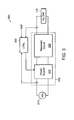
- FIG. 3 is a diagram illustrating a power supply 300 having a transformer-less power oscillator 310 for ozone generation in a single ozone cell 110 according to one embodiment.
- the power oscillator 310 includes a power source 320 coupled to a resonant circuit 330.
- the resonant circuit 330 is coupled, in turn, to the ozone cell 110.
- the power source 320 can be a switching power source.
- the power source 320 converts a regulated DC voltage (Vdc) from a DC voltage source 210 into a first AC voltage that is supplied to the resonant circuit 330.
- the first AC voltage from the power source 320 has a frequency substantially close to the resonant frequency of the resonant circuit 330.
- the resonant circuit 330 applies a substantially resonant second AC voltage to the ozone cell 110 causing an electrical discharge or flux within the ozone cell 110.
- the power supply 300 is able to provide high voltage AC power (a second AC voltage) needed for ozone generation in the ozone cell 110 without the use of a transformer.
- a controller 340 provides control signals to the power source 320 that cause the power source 320 to modulate the frequency and/or duty cycle of the first AC voltage resulting in the resonant circuit 330 providing a substantially second AC resonant voltage having a desired magnitude to the ozone cell 110.
- the second resonant AC voltage can be 4.5 kVpk at 30 kHz.
- the controller 340 compares a reference current REF with a sensed input current at the power source 320 and sends control signals (gate control signals) to the power source 320 to make adjustments to the operating frequency or duty cycle of the power source 320 to obtain the desired magnitude.
- the first AC voltage can be modulated by the controller 340 using pulse-width modulation and/or frequency modulation.
- the controller 340 can be configured to sense voltage, current, or a combination thereof to determine and control the desired resonant voltage.
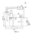
- FIG. 4 is a diagram illustrating a power supply 400 having a transformer-less power oscillator 404 for ozone generation in a single ozone cell 110 according to a particular embodiment.
- the resonant circuit 420 is a series resonant circuit including a resonant inductor 422 coupled in series with a resonant capacitor 424
- the ozone cell 110 is coupled in parallel with the resonant capacitor 424.
- the resonant capacitor 424 can be a separate individual capacitor, the natural capacitance of the ozone cell 110, or a combination thereof.
- the power source 410 is a half bridge inverter including two switching elements 412a, 412b connected in series.
- the switching elements 412a, 412b can be MOSFETs, BJTs, IGBTs and/or any other type switching elements known in the art.
- the electrical connection between the switching elements 412a, 412b is connected to the resonant circuit 420.
- the power source 410 can also be a full bridge inverter as shown in FIGS. 8A and 8B .
- a DC power supply 210 supplies a regulated DC voltage (Vdc) to the power source/half bridge inverter 410.
- Control signals from the controller 340 are provided to a gate driver 540 ( FIGS. 5A and 5B ) that causes the switches 412a, 412b to turn on and off resulting in the half bridge inverter 410 supplying the first AC voltage having a frequency substantially close to the resonant frequency of the series resonant circuit 420.
- the first AC voltage applied to the resonant circuit 420 can be square wave pulses with a controlled duty cycle.
- the control signals can also change the duty cycle of the half bridge inverter 410 to alter the magnitude of the second resonant AC voltage applied to the ozone cell 110.
- the series resonant circuit 420 In response to receiving the first AC voltage from the half bridge inverter 410, the series resonant circuit 420 provides a resonant or substantially second resonant AC voltage across the ozone cell 110 such that an electrical discharge or flux is provided within the cell to effect conversion of oxygen (O 2 ) to ozone (O 3 ). Particularly, the resonant circuit 420 converts the applied square wave pulses with a controlled duty cycle to a high voltage sine wave of controlled amplitude. According to one embodiment, the frequency and magnitude of the second resonant AC voltage is approximately 4.5 kVpk at 30 kHz.
- the ratio of ozone (O 3 ) to oxygen (O 2 ) depends on the amount of power supplied to the ozone cells 110.
- the power applied to the ozone cell 110 increases in proportion to the voltage applied to the ozone cell 110 and is regulated by the controller 340 in accordance with the reference signal REF as described above.
- the controller 340 can alter the concentration of ozone.
- the resonant frequency changes with even a small variation in inductance and capacitance.
- the resonant circuit 420 should have a high Q factor (greater than or equal to 10) to eliminate the need for transformer. Therefore, the controller 340 should be independent of the resonant component variation.
- FIGS. 5A and 5B show a detailed schematic of embodiments of a controller 500.
- the major components of the controller 500 include a pulse-width modulated integrated circuit (PWM IC) 510, a first operational/error amplifier 520, a second operational/error amplifier 530, a gate driver circuit 540, a first resistor 550, and a second resistor 560.
- PWM IC pulse-width modulated integrated circuit
- FIG. 5A shows one embodiment of a frequency modulated controller 500'.
- the operational amplifier/error amplifier 520 compares the sensed DC input current 522 with the set point DC current 524.
- the resistors 550, 560 control the frequency of the PWM IC 510.
- the output of the error amplifier 520 controls the current flowing through the resistor 550 by pulling it up or down and thus controls the frequency of the controller 510.
- the controller 500' includes an auto tuning circuit that ensures the initial frequency generated by the error amplifier 520 is the maximum operating frequency of the resonant circuit 420 ( FIG. 4 ).
- the tuning circuit includes a resistor 526, a capacitor 528, and a small offset voltage at the sensed input of the error amplifier 520.
- the DC current set point 524 slowly increases from zero to its set point through a delay created by the resistor 526 and capacitor 528.
- the offset voltage at the error amplifier 520 ensures that the frequency generated by the error amplifier is the maximum operating frequency of the circuit.
- the maximum resonant frequency is determined by considering the maximum tolerance on the resonant circuit elements and the capacity of the switching devices.
- FIG. 6 shows a graph showing the relationship between the set point power and the resonant frequency. As shown, as the set point power increases, the pulse-width modulation frequency starts reducing from its maximum value toward maximum power. That is, pulse-width modulation frequency walks over the resonant curve to achieve the maximum power.
- the controller 500' includes a second operational amplifier/error amplifier 530.
- the error amplifier 530 controls the resonant voltage of the ozone cell 110 by comparing the sensed resonant current 532 to the set point resonant current 534.
- FIG. 5B shows one embodiment of a pulse-width modulation controller 500".
- the operation of the pulse-width modulation controller 500" is similar to the operation with respect to the frequency modulated controller 500' as described above.
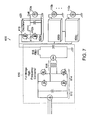
- FIG. 7 is a diagram illustrating a power supply 600 having multiple transformer-less power oscillators 404a...404n for ozone generation across multiple ozone cells 110a...110n according to one embodiment.
- the regulated DC voltage (Vdc) (e.g, approximately 400V) is provided by a known full bridge high frequency converter 610.
- the high frequency converter 610 includes a rectifier stage 612, a full bridge switching stage 614, a transformer stage 616, and a filter stage 618.
- Other circuits known to those skilled in the art can also be implemented to provide the regulated DC voltage.
- the power oscillators 404a...404n are coupled to a corresponding/respective ozone cell 110a...110n to provide the high voltage AC power.
- Each oscillator 404 includes a power source 410 coupled to a resonant circuit 420.
- the power sources 410 are half bridge inverters implemented using MOSFET switching devices 412a, 412b. Other switching devices known to those skilled in the art may also be utilized. Also, mixed implementations of half-bridge oscillators, full-bridge oscillators, and other known devices may be employed. The operation of the illustrated embodiment is similar to the operation described with respect to FIGS. 1 and 4 .
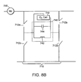
- FIGS. 8A and 8B are diagrams illustrating a power supply 700 having a transformer-less power oscillator for ozone generation in a single ozone cell 110 according to other particular embodiments.
- the power source 710 is implemented as a full bridge converter with four switching elements 712a, 712b, 712c, 712d coupled as shown.
- a voltage supply 210 supplies regulated DC voltage (Vdc) to the full bridge converter 710.
- Vdc regulated DC voltage
- the full bridge converter 710 is coupled to a series resonant circuit 720 having a resonant inductor 722 coupled in series with a resonant capacitor 724.
- the resonant circuit 720 is coupled, in turn, to an ozone cell 110 as shown.
- a current supply 730 supplies a regulated DC current (Idc) to the full bridge converter 710.
- the full bridge converter 710 is coupled to a parallel resonant circuit 740 having a resonant inductor 742 coupled in parallel to a resonant capacitor 744.
- the resonant circuit 740 is coupled, in turn, to an ozone cell 110 as shown.
- the resonant capacitor can be a separate individual capacitor or can be the natural capacitance of the ozone cell 110 or combination of both an individual capacitor and natural capacitance of the cell.
Landscapes
- Chemical & Material Sciences (AREA)
- Organic Chemistry (AREA)
- Engineering & Computer Science (AREA)
- Power Engineering (AREA)
- Inorganic Chemistry (AREA)
- General Health & Medical Sciences (AREA)
- Health & Medical Sciences (AREA)
- Toxicology (AREA)
- Chemical Kinetics & Catalysis (AREA)
- Oxygen, Ozone, And Oxides In General (AREA)
- Inverter Devices (AREA)
- Dc-Dc Converters (AREA)
- Generation Of Surge Voltage And Current (AREA)
Abstract
Description
- Ozone is useful for numerous applications that require a high level of oxidation. For example, ozone is useful for disinfection of drinking water and has been used for water treatment since the early 1900s. More recently, ozone has been used for semiconductor device processing. One application for ozone in semiconductor device processing is forming insulating layers on semiconductor wafers by growing insulating films or by oxidizing thin films on the wafer. For example, high deposition rate chemical vapor deposition of high quality SiO2 can be accomplished by using a TEOS/ozone process.
- Another application for ozone in semiconductor device processing is for cleaning semiconductor wafers and the processing chambers of semiconductor processing equipment. Ozone is particularly useful for removing hydrocarbons from the surface of semiconductor wafers or from processing chambers. Using ozone for cleaning is advantageous because it avoids the use of dangerous chemicals which require costly disposal. In contrast, ozone does not present a toxic waste disposal problem because ozone decays to oxygen without residues.
- Ozone can be generated from oxygen according to a so-called "silent discharge principle." For instance, ozone can be generated by exposing high purity oxygen to an electrical discharge or an electrical flux. The discharge or flux excites the oxygen molecules, breaking them into their atomic state. The atoms then recombine into a mixture of ozone (O3) and oxygen (O2).
- Ozone (O3) is typically produced by passing oxygen through an ozone cell where it is acted upon by an electrical discharge causing the dissolution and recombination of the oxygen atoms into ozone molecules. The electrical discharge or electrical flux needed for ozone generation is produced by applying a high voltage AC power across opposing plates of the ozone cell. The high voltage AC power is produced from transformer-based power oscillators.
- Disadvantages of a transformer-based power supply (an oscillator) typically include high cost, limited reliability, and limited range of operation. For example, the high cost is typically due to the high-voltage transformer with multiple windings and special potting requirements for cooling and insulation. Limited reliability is typically due to the topology of the self-oscillator, high voltage corona caused by the dependence of the potting quality, and use of single source unique parts. Limited range of operation with respect to the regulated output voltage is typically due to the self-oscillator topology and use of transformer feedback for the transistor's gate drive.
- The present invention is directed to a method and apparatus for supplying power using a power supply including transformer-less high voltage power oscillators for ozone generation. Embodiments of the present invention can reduce cost, increase reliability and operation range of ozone generators.
- One embodiment includes a power supply having a power source and a resonant circuit coupled to the power source, the power source providing a first AC voltage to the resonant circuit, the resonant circuit providing a second AC voltage for use by an ozone generating unit, the second AC voltage being greater than the first AC voltage. The resonant circuit can apply a substantially resonant voltage to the ozone generating unit in response to the first AC voltage having a frequency substantially close to the resonant frequency of the resonant circuit.
- In some embodiments, the resonant circuit can be a series resonant circuit including a resonant inductor coupled in series with a resonant capacitor. The resonant capacitor can be an individual capacitor, a natural capacitance of the ozone generating unit, or a combination of both an individual capacitor and natural capacitance of the ozone generating unit. The resonant circuit has a q-factor greater than or equal to 10. In other embodiments, the resonant circuit can be a parallel resonant circuit including a resonant inductor coupled in parallel with a resonant capacitor. The resonant capacitor can be an individual capacitor, a natural capacitance of the ozone generating unit, or a combination of both an individual capacitor and natural capacitance of the ozone generating unit.
- The power source can be a half bridge inverter, a full bridge inverter, and/or a switching power source. The switching elements can be MOSFETs, BJTs, IGBTs, and/or any other type of switching elements.
- The power supply can further include a controller providing signals to the power source that cause the power source to modulate the first AC voltage, resulting in the second AC voltage having a desired voltage magnitude. The first AC voltage can be modulated using pulse width modulation and/or frequency modulation. The controller can provide signals to the power source that allows the resonant circuit to operate at its maximum operating resonant frequency. The controller can tune to the maximum operating frequency of the resonant circuit by comparing a sensed input DC current to a set point input current. The controller can control a resonant voltage of the ozone generating unit during self-tuning to the maximum operating frequency of the resonant circuit by comparing a sensed resonant current to a set point resonant current.
- Embodiments of the invention also include a power supply for ozone generation. Other embodiments of the invention may be applied for supplying power for generation of any reactive gases.
- Advantages of the embodiments of the invention include reduced cost and increased reliability and operation range of ozone generators by eliminating the need for a transformer.
- Using a high Q resonant circuit (Q≥10 typically for an ozone generator) instead of a transformer implies that the circuit resonant frequency peak is narrow. Since its center frequency depends on circuit elements with tolerances often wider than the resonance peak width, control of such a circuit can be a problem. A circuit to control high Q resonant circuits allows realization of the advantages above in both ozone generators and in resonant power supplies for other applications.
- The foregoing and other objects, features and advantages of the invention will be apparent from the following more particular description of preferred embodiments of the invention. The drawings are not necessarily to scale, emphasis instead being placed upon illustrating the principles of the invention.
-
FIG. 1 is a diagram illustrating a typical ozone generator; -
FIG. 2 is a diagram that illustrates a transformer-based power supply used in an ozone generator according to the prior art; -
FIG. 3 is a diagram illustrating a power supply having a transformer-less power oscillator for ozone generation in a single ozone cell according to one embodiment; -
FIG. 4 is a diagram illustrating a power supply having a transformer-less power oscillator for ozone generation in a single ozone cell according to a particular embodiment; -
FIG. 5A shows a detailed schematic of one embodiment of a frequency modulation controller; -
FIG. 5B shows a detailed schematic of one embodiment of a pulse-width modulation controller; -
FIG. 6 shows a graph showing the relationship between set point power and resonant frequency; -
FIG. 7 is a diagram illustrating a power supply having multiple transformer-less power oscillators for ozone generation across multiple ozone cells according to one embodiment; and -
FIGS. 8A and8B are diagrams illustrating a power supply having a transformer-less power oscillator for ozone generation in a single ozone cell according to other particular embodiments. -
FIG. 1 is a diagram illustrating atypical ozone generator 100. Theozone generator 100 includes a bank of ozone generating units, referred to herein asozone cells 110a...110n. Oxygen (O2) is supplied to eachozone cell 110 through anoxygen inlet 120 for conversion into a mixture of ozone (O3) and oxygen (O2). The resulting ozone mixture flows out of theozone generator 100 through anozone outlet 130. - Components of the
ozone cell 110 typically include opposing electrode plates (not shown) and a dielectric barrier (not shown). The dielectric barrier is positioned against one of the electrode plates, forming a channel between the dielectric barrier and the opposing electrode plate. In operation, oxygen (O2) passing through the channel is acted upon by an electrical discharge causing the dissolution and recombination of the oxygen atoms into ozone molecules. To cause the electrical discharge or flux, high voltage AC power is applied across the opposing electrode plates of eachozone cell 110. - The high voltage AC power is provided by a bank of
power oscillators 140a...140n with each oscillator 140 supplying power to arespective ozone cell 110. The power oscillators 140 are coupled to a commonDC power supply 150 that can convert single-phase or three-phaseAC line voltage 152 into a regulated DC voltage (Vdc). Each oscillator 140, in turn, converts the regulated DC voltage (Vdc) into high voltage AC power that is supplied to a corresponding/respective ozone cell 110, resulting in the electrical discharge or electrical flux needed for ozone generation. An exemplary embodiment of theozone cell 110 can be found inU.S. Patent 5,932,180 , the entire contents of which are incorporated herein by reference. - Generally, the power oscillators 140 are implemented using transformers to generate high voltage AC power.
FIG. 2 is a diagram that illustrates a transformer-basedpower supply 200 used in an ozone generator according to the prior art. The illustratedpower supply 200 consists of aDC power supply 210 and two additional stages: (1) abuck converter 220 for regulation of output power and (2) a self oscillating push-pull converter 230 that includes atransformer 232 to generate the high voltage AC power across theozone cell 110. -
FIG. 3 is a diagram illustrating apower supply 300 having atransformer-less power oscillator 310 for ozone generation in asingle ozone cell 110 according to one embodiment. Thepower oscillator 310 includes apower source 320 coupled to aresonant circuit 330. Theresonant circuit 330 is coupled, in turn, to theozone cell 110. Thepower source 320 can be a switching power source. - In operation, the
power source 320 converts a regulated DC voltage (Vdc) from aDC voltage source 210 into a first AC voltage that is supplied to theresonant circuit 330. Preferably, the first AC voltage from thepower source 320 has a frequency substantially close to the resonant frequency of theresonant circuit 330. In response, theresonant circuit 330 applies a substantially resonant second AC voltage to theozone cell 110 causing an electrical discharge or flux within theozone cell 110. Thus, by coupling theresonant circuit 330 to thepower source 320, thepower supply 300 is able to provide high voltage AC power (a second AC voltage) needed for ozone generation in theozone cell 110 without the use of a transformer. - With reference to
FIG. 3 , acontroller 340 provides control signals to thepower source 320 that cause thepower source 320 to modulate the frequency and/or duty cycle of the first AC voltage resulting in theresonant circuit 330 providing a substantially second AC resonant voltage having a desired magnitude to theozone cell 110. In some embodiments the second resonant AC voltage can be 4.5 kVpk at 30 kHz. - In operation, the
controller 340 compares a reference current REF with a sensed input current at thepower source 320 and sends control signals (gate control signals) to thepower source 320 to make adjustments to the operating frequency or duty cycle of thepower source 320 to obtain the desired magnitude. The first AC voltage can be modulated by thecontroller 340 using pulse-width modulation and/or frequency modulation. In some embodiments, thecontroller 340 can be configured to sense voltage, current, or a combination thereof to determine and control the desired resonant voltage. -
FIG. 4 is a diagram illustrating apower supply 400 having atransformer-less power oscillator 404 for ozone generation in asingle ozone cell 110 according to a particular embodiment. In the illustrated embodiment, theresonant circuit 420 is a series resonant circuit including aresonant inductor 422 coupled in series with aresonant capacitor 424 Theozone cell 110 is coupled in parallel with theresonant capacitor 424. Theresonant capacitor 424 can be a separate individual capacitor, the natural capacitance of theozone cell 110, or a combination thereof. In the illustrated embodiment, thepower source 410 is a half bridge inverter including two switchingelements switching elements elements resonant circuit 420. Thepower source 410 can also be a full bridge inverter as shown inFIGS. 8A and8B . - In operation, a
DC power supply 210 supplies a regulated DC voltage (Vdc) to the power source/half bridge inverter 410. Control signals from thecontroller 340 are provided to a gate driver 540 (FIGS. 5A and5B ) that causes theswitches half bridge inverter 410 supplying the first AC voltage having a frequency substantially close to the resonant frequency of the seriesresonant circuit 420. Particularly, the first AC voltage applied to theresonant circuit 420 can be square wave pulses with a controlled duty cycle. The control signals can also change the duty cycle of thehalf bridge inverter 410 to alter the magnitude of the second resonant AC voltage applied to theozone cell 110. In response to receiving the first AC voltage from thehalf bridge inverter 410, the seriesresonant circuit 420 provides a resonant or substantially second resonant AC voltage across theozone cell 110 such that an electrical discharge or flux is provided within the cell to effect conversion of oxygen (O2) to ozone (O3). Particularly, theresonant circuit 420 converts the applied square wave pulses with a controlled duty cycle to a high voltage sine wave of controlled amplitude. According to one embodiment, the frequency and magnitude of the second resonant AC voltage is approximately 4.5 kVpk at 30 kHz. - The ratio of ozone (O3) to oxygen (O2) depends on the amount of power supplied to the
ozone cells 110. The power applied to theozone cell 110 increases in proportion to the voltage applied to theozone cell 110 and is regulated by thecontroller 340 in accordance with the reference signal REF as described above. Thus, by changing the operating frequency or duty cycle of thehalf bridge inverter 410, thecontroller 340 can alter the concentration of ozone. Further, the resonant frequency changes with even a small variation in inductance and capacitance. Thus, theresonant circuit 420 should have a high Q factor (greater than or equal to 10) to eliminate the need for transformer. Therefore, thecontroller 340 should be independent of the resonant component variation. -
FIGS. 5A and5B show a detailed schematic of embodiments of acontroller 500. The major components of thecontroller 500 include a pulse-width modulated integrated circuit (PWM IC) 510, a first operational/error amplifier 520, a second operational/error amplifier 530, agate driver circuit 540, afirst resistor 550, and asecond resistor 560. -
FIG. 5A shows one embodiment of a frequency modulated controller 500'. In operation, the operational amplifier/error amplifier 520 compares the sensed DC input current 522 with the set point DC current 524. Theresistors PWM IC 510. The output of theerror amplifier 520 controls the current flowing through theresistor 550 by pulling it up or down and thus controls the frequency of thecontroller 510. The controller 500' includes an auto tuning circuit that ensures the initial frequency generated by theerror amplifier 520 is the maximum operating frequency of the resonant circuit 420 (FIG. 4 ). - The tuning circuit includes a
resistor 526, acapacitor 528, and a small offset voltage at the sensed input of theerror amplifier 520. In operation, when the tuning circuit powers up, the DCcurrent set point 524 slowly increases from zero to its set point through a delay created by theresistor 526 andcapacitor 528. In that time, the offset voltage at theerror amplifier 520 ensures that the frequency generated by the error amplifier is the maximum operating frequency of the circuit. The maximum resonant frequency is determined by considering the maximum tolerance on the resonant circuit elements and the capacity of the switching devices. -
FIG. 6 shows a graph showing the relationship between the set point power and the resonant frequency. As shown, as the set point power increases, the pulse-width modulation frequency starts reducing from its maximum value toward maximum power. That is, pulse-width modulation frequency walks over the resonant curve to achieve the maximum power. - It is important to control the
ozone cell 110 voltage because theozone cell 110 voltage can rise to a very high voltage during auto-tuning of the frequency for maximum power. Thus, the controller 500' includes a second operational amplifier/error amplifier 530. Theerror amplifier 530 controls the resonant voltage of theozone cell 110 by comparing the sensed resonant current 532 to the set point resonant current 534. - The resonant current can also be controlled by using pulse-width modulation.
FIG. 5B shows one embodiment of a pulse-width modulation controller 500". The operation of the pulse-width modulation controller 500" is similar to the operation with respect to the frequency modulated controller 500' as described above. -
FIG. 7 is a diagram illustrating apower supply 600 having multipletransformer-less power oscillators 404a...404n for ozone generation acrossmultiple ozone cells 110a...110n according to one embodiment. In the illustrated embodiment, the regulated DC voltage (Vdc) (e.g, approximately 400V) is provided by a known full bridgehigh frequency converter 610. Thehigh frequency converter 610 includes arectifier stage 612, a fullbridge switching stage 614, atransformer stage 616, and afilter stage 618. Other circuits known to those skilled in the art can also be implemented to provide the regulated DC voltage. Thepower oscillators 404a...404n are coupled to a corresponding/respective ozone cell 110a...110n to provide the high voltage AC power. Eachoscillator 404 includes apower source 410 coupled to aresonant circuit 420. In the illustrated embodiment, thepower sources 410 are half bridge inverters implemented usingMOSFET switching devices FIGS. 1 and4 . -
FIGS. 8A and8B are diagrams illustrating apower supply 700 having a transformer-less power oscillator for ozone generation in asingle ozone cell 110 according to other particular embodiments. In both embodiments, thepower source 710 is implemented as a full bridge converter with fourswitching elements - As shown in
FIG. 8A , avoltage supply 210 supplies regulated DC voltage (Vdc) to thefull bridge converter 710. Thefull bridge converter 710 is coupled to a seriesresonant circuit 720 having aresonant inductor 722 coupled in series with aresonant capacitor 724. Theresonant circuit 720 is coupled, in turn, to anozone cell 110 as shown. - As shown in
FIG. 8B , acurrent supply 730 supplies a regulated DC current (Idc) to thefull bridge converter 710. Thefull bridge converter 710 is coupled to a parallelresonant circuit 740 having aresonant inductor 742 coupled in parallel to aresonant capacitor 744. Theresonant circuit 740 is coupled, in turn, to anozone cell 110 as shown. - In either embodiment, the resonant capacitor can be a separate individual capacitor or can be the natural capacitance of the
ozone cell 110 or combination of both an individual capacitor and natural capacitance of the cell. - While this invention has been particularly shown and described with references to preferred embodiments thereof, it will be understood by those skilled in the art that various changes in form and details may be made therein without departing from the scope of the invention encompassed by the appended claims.
- Although the invention can be defined as stated in the attached claims, it is to be understood that the present invention can alternatively also be defined as stated in the following embodiments:
- 1. A power supply, comprising:
- a power source; and
- a resonant circuit coupled to the power source;
- the power source providing a first AC voltage to the resonant circuit, the resonant circuit providing a second AC voltage for use by an ozone generating unit, the second
- AC voltage being greater than the first AC voltage.
- 2. The power supply of embodiment 1, wherein the resonant circuit applies a substantially
resonant voltage to the ozone generating unit in response to the first AC voltage having a frequency substantially close to the resonant frequency of the resonant circuit. - 3. The power supply of embodiment 1, wherein the resonant circuit is a series resonant circuit including a resonant inductor coupled in series with a resonant capacitor.
- 4. The power supply of embodiment 3, wherein the resonant capacitor is an individual capacitor, a natural capacitance of the ozone generating unit, or a combination of both an individual capacitor and natural capacitance of the ozone generating unit.
- 5. The power supply of embodiment 3, wherein the resonant circuit has a q-factor greater than or equal to 10.
- 6. The power supply of embodiment 1, wherein the resonant circuit is a parallel resonant circuit including a resonant inductor coupled in parallel with a resonant capacitor.
- 7. The power supply of embodiment 6, wherein the resonant capacitor is an individual capacitor, a natural capacitance of the ozone generating unit, or a combination of both an individual capacitor and natural capacitance of the ozone generating unit.
- 8. The power supply of embodiment 1, wherein the power source is a half bridge inverter.
- 9. The power supply of embodiment 1, wherein the power source is a full bridge inverter.
- 10. The power supply of embodiment 1, wherein the power source is a switching power source.
- 11. The power supply of
embodiment 10, wherein the switching elements are MOSFETs, BJTs, or IGBTs. - 12. The power supply of embodiment 1, further comprising:
- a controller providing signals to the power source that cause the power source to modulate the first AC voltage, resulting in the second AC voltage having a desired
- voltage magnitude.
- 13. The power supply of embodiment 12, wherein the first AC voltage is modulated using pulse width modulation.
- 14. The power supply of embodiment 12, wherein the first AC voltage is modulated using
frequency modulation. - 15. The power supply of embodiment 12, wherein the controller provides signals to the power source that allows the resonant circuit to operate at or near its resonant frequency.
- 16. The power supply of
embodiment 15, wherein the controller tunes to the maximum operating frequency of the resonant circuit and approaches the resonant frequency of the circuit to obtain the desired operating level, by comparing a sensed input DC current to a set point input current. - 17. The power supply of
embodiment 16, wherein the controller controls a resonant voltage of the ozone generating unit during self-tuning to the maximum operating frequency of the resonant circuit and approaches the resonant frequency of the circuit by comparing a sensed resonant current to a set point resonant current. - 18. A method of supplying power for ozone generation, comprising:
- coupling a resonant circuit between a power source and an ozone generating unit; providing a first AC voltage from the power source to the resonant circuit; and
- providing a second AC voltage from the resonant circuit to the ozone generating unit, the second AC voltage being greater than the first AC voltage.
- 19. The method of embodiment 18, further comprising:
- providing a substantially resonant voltage from the resonant circuit to the ozone generating unit in response to the first AC voltage having a frequency substantially close to the resonant frequency of the resonant circuit.
- 20. The method of embodiment 18, further comprising:
- forming a series resonant circuit by coupling a resonant inductor in series with a resonant capacitor.
- 21. The method of
embodiment 20, wherein the resonant capacitor is an individual capacitor, a natural capacitance of the ozone generating unit, or a combination of both an individual capacitor and natural capacitance of the ozone generating unit. - 22. The method of
embodiment 20, wherein the resonant circuit has a q-factor greater than or equal to 10. - 23. The method of embodiment 18, further comprising:
- forming a parallel resonant circuit by coupling a resonant inductor in parallel with a resonant capacitor.
- 24. The method of embodiment 23, wherein the resonant capacitor is an individual capacitor, a natural capacitance of the ozone generating unit, or a combination of both an individual capacitor and natural capacitance of the ozone generating unit.
- 25. The method of embodiment 18, wherein the power source is a half bridge inverter.
- 26. The method of embodiment 18, wherein the power source is a full bridge inverter.
- 27. The method of embodiment 18, wherein the power source is a switching power source.
- 28. The method of embodiment 27, wherein the switching elements are MOSFETs, BJTs, or IGBTs.
- 29. The method of embodiment 18, further comprising:
- providing signals to the power source;
- in response to the signals, modulating the first AC voltage,
- resulting in the
- second AC voltage having a desired voltage magnitude.
- 30. The method of embodiment 29, wherein modulating the first AC voltage comprises:
- modulating pulse width of the first AC voltage.
- 31. The method of embodiment 29, wherein modulating the first AC voltage comprises:
- modulating frequency of the first AC voltage.
- 32. The method of embodiment 29, wherein the provided signals to the power source allow the resonant circuit to operate at or near its resonant frequency.
- 33. The method of embodiment 32, further comprising tuning to the maximum operating frequency of the resonant circuit and approaching the resonant frequency of the circuit to obtain the desired operating level, by comparing a sensed input DC current to a set point input current.
- 34. The method of embodiment 33, further comprising:
- controlling a resonant voltage of the ozone generating unit during tuning to the maximum operating frequency of the resonant circuit; and
- approaching the resonant frequency of the circuit by comparing a sensed resonant current to a set point resonant current.
- 35. A method for supplying power for ozone generation, comprising:
- coupling a plurality of resonant circuits between a plurality of power sources and a plurality of ozone generating units;
- providing a first AC voltage from each of the plurality of power sources to a respective resonant circuit; and providing a second AC voltage from each respective resonant circuit to a respective ozone generating unit, the second AC voltage being greater than the first AC voltage.
- 36. A power supply for ozone generation, comprising:
- a plurality of power sources;
- a plurality of resonant circuits coupled between the plurality sources and a
- plurality ozone generating units; and
- each of the plurality of power sources providing a first AC voltage to a respective resonant circuit, the respective resonant circuit providing a second AC voltage to a respective ozone generating unit, the second AC voltage being greater than the first AC voltage.
- 37. A method of supplying power for ozone generation, comprising:
- means for coupling a resonant circuit between a power source and an ozone
- generating unit;
- means for providing a first AC voltage from the power source .to the resonant circuit; and
- means for providing a second AC voltage from the resonant circuit to the ozone generating unit, the second AC voltage being greater than the first AC voltage.
- 38. A power supply, comprising:
- a power source; and
- a resonant circuit coupled to the power source; and
- an ozone generator coupled to the resonant circuit.
- 39. A switch-mode power supply, comprising:
- a high Q resonant circuit; and
- a controller coupled to the high Q resonant circuit, wherein the controller
- modulates the frequency by (i) starting from an extreme high or low value, (ii)
- approaching the resonant frequency of the high Q resonant circuit to obtain a desired level of output, and (iii) providing for a wide tolerance in the resonant component values.
Claims (19)
- A power supply, comprising:a transformer-less oscillator comprising a power source and a resonant circuit; and,the resonant circuit having a q-factor and being directly coupled between the power source and an ozone generating unit, where the q-factor is greater than or equal to 10,the power source being configured to providing a first AC voltage to the resonant circuit, and the resonant circuit being configured to providing a second AC voltage for to the ozone generating unit, the second AC voltage being greater than the first AC voltage and sufficient to power the ozone generating unit.
- The power supply of claim 1, wherein the resonant circuit applies a substantially resonant voltage to the ozone generating unit in response to the first AC voltage having a frequency substantially close to the resonant frequency of the resonant circuit.
- The power supply of claim 1, wherein the resonant capacitor is an individual capacitor, a natural capacitance of the ozone generating unit, or a combination of both an individual capacitor and natural capacitance of the ozone generating unit.
- The power supply of claim 1, wherein the resonant circuit is a parallel resonant circuit including a resonant inductor coupled in parallel with a resonant capacitor.
- The power supply of claim 4, wherein the resonant capacitor is an individual capacitor, a natural capacitance of the ozone generating unit, or a combination of both an individual capacitor and natural capacitance of the ozone generating unit.
- The power supply of claim 1, wherein the power source is a half bridge inverter.
- The power supply of claim 1, wherein the power source is a full bridge inverter.
- The power supply of claim 1, wherein the power source is a switching power source.
- The power supply of claim 8, wherein the switching elements are MOSFETs, BJTs, or IGBTs.
- The power supply of claim 1, further comprising:a controller providing signals to the power source that cause the power source to modulate the first AC voltage, resulting in the second AC voltage having a desired voltage magnitude.
- The power supply of claim 10, wherein the first AC voltage is modulated using pulse width modulation.
- The power supply of claim 10, wherein the first AC voltage is modulated using frequency modulation.
- The power supply of claim 10, wherein the controller provides signals to the power source that allows the resonant circuit to operate at or near its resonant frequency.
- The power supply of claim 13, wherein the controller tunes to the maximum operating frequency of the resonant circuit and approaches the resonant frequency of the circuit to obtain the desired operating level, by comparing a sensed input DC current to a set point input current.
- The power supply of claim 14, wherein the controller controls a resonant voltage of the ozone generating unit during self-tuning to the maximum operating frequency of the resonant circuit and approaches the resonant frequency of the circuit by comparing a sensed resonant current to a set point resonant current.
- The power supply of claim 1 for ozone generation, comprising:a plurality of transformer-less oscillators, each comprising a power source and a resonant circuit;each resonant circuit having a q-factor, and being directly coupled between a respective power source and one of a plurality of ozone generating units, such that each power source and ozone generating unit are coupled to only one resonant circuit where the q-factor is greater than or equal to 10; andeach power source being configured to providing a first AC voltage to a respective resonant circuit the respective resonant circuit being configured to providing a second AC voltage to a respective ozone generating unit the second AC voltage being greater than the first AC voltage and sufficient to power said respective ozone generating unit.
- The power supply of claim 1, wherein the power supply comprises a switch-mode power supply, wherein the power source comprises a switching power source, comprising:a high Q resonant circuit; anda controller coupled to the high Q resonant circuit, wherein the controller is configured to modulate the frequency by(i) starting from an extreme high or low value,(ii) approaching the resonant frequency of the high Q resonant circuit to obtain a desired level of output, and(iii) providing for a wide tolerance in the resonant component values.
- A method for supplying power for ozone generation, comprising:providing a transformer-less oscillator, comprising a power source and a resonant circuit;directly coupling the resonant circuit, the resonant circuit having a q-factor, between a respective power source and an ozone generating unit, such that the power source and ozone generating unit are coupled to the resonant circuit, where the q-factor is greater than or equal to 10;providing a first AC voltage from the power source to the resonant circuit; andproviding a second AC voltage from the resonant circuit to the ozone generating unit, the second AC voltage being greater than the first AC voltage and sufficient to power said ozone generating unit.
- The method of claim 18, comprising:providing a plurality of transformer-less oscillators, each comprising a power source and a resonant circuit;directly coupling each resonant circuit, each resonant circuit having a q-factor, between a respective power source and one of a plurality of ozone generating units, such that each power source and ozone generating unit are coupled to only one resonant circuit, where the q-factor is greater than or equal to 10;providing a first AC voltage from each power source to a respective resonant circuit; andproviding a second AC voltage from each respective resonant circuit to a respective ozone generating unit, the second AC voltage being greater than the first AC voltage and sufficient to power said respective ozone generating unit.
Applications Claiming Priority (3)
| Application Number | Priority Date | Filing Date | Title |
|---|---|---|---|
| US70844505P | 2005-08-16 | 2005-08-16 | |
| PCT/US2006/031664 WO2007035216A1 (en) | 2005-08-16 | 2006-08-14 | Load resonant type power supply for ozonizer |
| EP06836103.9A EP1929615B1 (en) | 2005-08-16 | 2006-08-14 | Load resonant type power supply for ozonizer |
Related Parent Applications (3)
| Application Number | Title | Priority Date | Filing Date |
|---|---|---|---|
| EP06836103.9 Division | 2006-08-14 | ||
| EP06836103.9A Division-Into EP1929615B1 (en) | 2005-08-16 | 2006-08-14 | Load resonant type power supply for ozonizer |
| EP06836103.9A Division EP1929615B1 (en) | 2005-08-16 | 2006-08-14 | Load resonant type power supply for ozonizer |
Publications (3)
| Publication Number | Publication Date |
|---|---|
| EP2523336A2 true EP2523336A2 (en) | 2012-11-14 |
| EP2523336A3 EP2523336A3 (en) | 2013-05-29 |
| EP2523336B1 EP2523336B1 (en) | 2020-10-07 |
Family
ID=37719271
Family Applications (2)
| Application Number | Title | Priority Date | Filing Date |
|---|---|---|---|
| EP12174905.5A Not-in-force EP2523336B1 (en) | 2005-08-16 | 2006-08-14 | Load resonant type power supply for ozonizer |
| EP06836103.9A Not-in-force EP1929615B1 (en) | 2005-08-16 | 2006-08-14 | Load resonant type power supply for ozonizer |
Family Applications After (1)
| Application Number | Title | Priority Date | Filing Date |
|---|---|---|---|
| EP06836103.9A Not-in-force EP1929615B1 (en) | 2005-08-16 | 2006-08-14 | Load resonant type power supply for ozonizer |
Country Status (7)
| Country | Link |
|---|---|
| US (2) | US8226900B2 (en) |
| EP (2) | EP2523336B1 (en) |
| JP (2) | JP5355085B2 (en) |
| KR (1) | KR101323046B1 (en) |
| CN (2) | CN102664536B (en) |
| TW (1) | TWI393338B (en) |
| WO (1) | WO2007035216A1 (en) |
Families Citing this family (22)
| Publication number | Priority date | Publication date | Assignee | Title |
|---|---|---|---|---|
| GB2466664B (en) | 2009-01-06 | 2015-04-01 | Perlemax Ltd | Plasma microreactor apparatus, sterilisation unit and analyser |
| JP2011006284A (en) * | 2009-06-25 | 2011-01-13 | Toyota Motor Corp | Ozonizer |
| US20100329941A1 (en) * | 2009-06-30 | 2010-12-30 | Mark Edward Moore | Output control for ozone generators |
| SG178251A1 (en) * | 2009-08-11 | 2012-03-29 | Oxion Pte Ltd | Air ionizer electrode drive circuit and method |
| JP5461155B2 (en) * | 2009-11-24 | 2014-04-02 | 澤藤電機株式会社 | High voltage application device using pulse voltage and high voltage application method |
| CN105939030B (en) * | 2010-01-25 | 2019-06-18 | 飞利浦知识产权企业有限公司 | System and method for detecting data communications over a wireless power link |
| WO2011120586A1 (en) * | 2010-04-01 | 2011-10-06 | Telefonaktiebolaget L M Ericsson (Publ) | Switch control for a power converter |
| US8680777B2 (en) * | 2012-03-27 | 2014-03-25 | Mks Instruments, Inc. | Versatile zero-voltage switch resonant inverter for industrial dielectric barrier discharge generator applications |
| US9302912B2 (en) * | 2012-03-28 | 2016-04-05 | Mks Instruments, Inc. | Compact, configurable power supply for energizing ozone-producing cells |
| US20140008211A1 (en) | 2012-07-06 | 2014-01-09 | Pacific Ozone Technology, Inc. | Ozone cell power supply apparatus and method |
| CA2879543C (en) * | 2012-08-27 | 2017-09-12 | Bombardier Transportation Gmbh | Adaptive soft switching control for power converter |
| ES2934683T3 (en) * | 2012-10-05 | 2023-02-24 | De Nora Holdings Us Inc | Transformerless on-site generation |
| TWI491858B (en) * | 2013-03-15 | 2015-07-11 | Richtek Technology Corp | Temperature determination circuit and method thereof |
| CN106549590A (en) * | 2015-09-16 | 2017-03-29 | 台达电子工业股份有限公司 | Embedded power conversion device and power supply system applicable to same |
| TWI603177B (en) * | 2015-09-16 | 2017-10-21 | 台達電子工業股份有限公司 | Buried power conversion device and its suitable power conversion system |
| CN105892550B (en) * | 2016-06-06 | 2017-07-04 | 北方工业大学 | Method and device for adjusting output power of ozone generator |
| KR101909789B1 (en) * | 2016-11-24 | 2018-10-18 | 인하대학교 산학협력단 | Driving Circuit using the Series Resonance Method |
| KR101732531B1 (en) * | 2016-12-29 | 2017-05-08 | 주식회사 삼도환경 | Plasma generator for agriculture and agriculture using resonant power driver |
| JP2018164391A (en) * | 2017-03-24 | 2018-10-18 | 株式会社デンソー | Resonant inverter |
| CN110734041B (en) * | 2019-10-30 | 2021-08-10 | 福建龙净脱硫脱硝工程有限公司 | Control system and control method for power supply of high-power ozone generator |
| US11159124B2 (en) * | 2020-03-09 | 2021-10-26 | Biosense Webster (Israel) Ltd. | Sine-wave generation using pulsed D-class amplifier |
| CN113684491A (en) * | 2021-09-07 | 2021-11-23 | 柳大海 | Water capacitor high-frequency decomposition system |
Citations (1)
| Publication number | Priority date | Publication date | Assignee | Title |
|---|---|---|---|---|
| US5932180A (en) | 1994-08-31 | 1999-08-03 | Applied Science And Technology, Inc. | Ozone and other reactive gas generator cell and system |
Family Cites Families (19)
| Publication number | Priority date | Publication date | Assignee | Title |
|---|---|---|---|---|
| JP2532355B2 (en) * | 1981-03-19 | 1996-09-11 | 松下電器産業株式会社 | Inverter device |
| CH664952A5 (en) * | 1985-06-21 | 1988-04-15 | Bbc Brown Boveri & Cie | DEVICE FOR OZONE PRODUCTION AND METHOD FOR THE OPERATION THEREOF. |
| US5135725A (en) * | 1989-08-14 | 1992-08-04 | Infilco Degremont Inc. | Ozone generator equipment and methods |
| JP2940064B2 (en) * | 1990-04-24 | 1999-08-25 | 神鋼電機株式会社 | Inverter power supply for induction heating |
| WO1994025150A1 (en) * | 1991-04-15 | 1994-11-10 | Rez-Tek International, Inc. | Ozonation system for treatment of cooling tower water |
| US5285372A (en) * | 1991-10-23 | 1994-02-08 | Henkel Corporation | Power supply for an ozone generator with a bridge inverter |
| JPH092806A (en) * | 1995-06-20 | 1997-01-07 | Meidensha Corp | Ozonizer |
| JP3868624B2 (en) * | 1998-03-31 | 2007-01-17 | 三菱電機株式会社 | Power supply for plasma generation |
| US7555263B1 (en) | 1999-10-21 | 2009-06-30 | Broadcom Corporation | Adaptive radio transceiver |
| JP3540227B2 (en) * | 1999-12-17 | 2004-07-07 | 株式会社東芝 | Power converter |
| US6181079B1 (en) | 1999-12-20 | 2001-01-30 | Philips Electronics North America Corporation | High power electronic ballast with an integrated magnetic component |
| JP2001268910A (en) * | 2000-03-21 | 2001-09-28 | Sansha Electric Mfg Co Ltd | Power supply |
| JP2002171765A (en) * | 2000-11-30 | 2002-06-14 | Fuji Electric Co Ltd | Fuse blowing method for capacitive load and driving device for capacitive load using the same |
| TW494636B (en) | 2001-02-26 | 2002-07-11 | Realtek Semiconductor Co Ltd | Spread spectrum phase-locked loop circuit with adjustable spread bandwidth |
| JP2002271193A (en) | 2001-03-06 | 2002-09-20 | Fujitsu Ltd | Phase locked oscillator and communication device |
| JP2003125586A (en) * | 2001-10-15 | 2003-04-25 | Amada Eng Center Co Ltd | Power unit for plasma generation |
| FR2834392A1 (en) | 2001-12-28 | 2003-07-04 | St Microelectronics Sa | HIGH VOLTAGE OSCILLATOR HAVING FAST REACTION TIME |
| JP2003230280A (en) * | 2002-01-30 | 2003-08-15 | Toshiba Corp | Power converter |
| JP4220164B2 (en) | 2002-02-06 | 2009-02-04 | 東洋紡績株式会社 | Nucleic acid purification method, nucleic acid extraction solution used in the method, and nucleic acid purification reagent kit |
-
2006
- 2006-08-14 EP EP12174905.5A patent/EP2523336B1/en not_active Not-in-force
- 2006-08-14 KR KR1020087004458A patent/KR101323046B1/en active Active
- 2006-08-14 US US11/503,662 patent/US8226900B2/en active Active
- 2006-08-14 CN CN201210137285.4A patent/CN102664536B/en active Active
- 2006-08-14 CN CN2006800346516A patent/CN101288219B/en active Active
- 2006-08-14 EP EP06836103.9A patent/EP1929615B1/en not_active Not-in-force
- 2006-08-14 WO PCT/US2006/031664 patent/WO2007035216A1/en not_active Ceased
- 2006-08-14 JP JP2008527033A patent/JP5355085B2/en active Active
- 2006-08-16 TW TW095130091A patent/TWI393338B/en active
-
2012
- 2012-06-20 US US13/528,580 patent/US8641978B2/en active Active
-
2013
- 2013-02-01 JP JP2013018441A patent/JP2013085475A/en active Pending
Patent Citations (1)
| Publication number | Priority date | Publication date | Assignee | Title |
|---|---|---|---|---|
| US5932180A (en) | 1994-08-31 | 1999-08-03 | Applied Science And Technology, Inc. | Ozone and other reactive gas generator cell and system |
Also Published As
| Publication number | Publication date |
|---|---|
| JP2013085475A (en) | 2013-05-09 |
| CN101288219B (en) | 2013-04-03 |
| CN102664536B (en) | 2016-03-02 |
| KR20080034481A (en) | 2008-04-21 |
| US20130156648A1 (en) | 2013-06-20 |
| US8641978B2 (en) | 2014-02-04 |
| EP1929615B1 (en) | 2018-11-14 |
| US20070108040A1 (en) | 2007-05-17 |
| US8226900B2 (en) | 2012-07-24 |
| CN102664536A (en) | 2012-09-12 |
| KR101323046B1 (en) | 2013-10-29 |
| TWI393338B (en) | 2013-04-11 |
| CN101288219A (en) | 2008-10-15 |
| EP2523336B1 (en) | 2020-10-07 |
| EP1929615A1 (en) | 2008-06-11 |
| JP5355085B2 (en) | 2013-11-27 |
| TW200723659A (en) | 2007-06-16 |
| JP2009505626A (en) | 2009-02-05 |
| EP2523336A3 (en) | 2013-05-29 |
| WO2007035216A1 (en) | 2007-03-29 |
Similar Documents
| Publication | Publication Date | Title |
|---|---|---|
| US8641978B2 (en) | Power supply including transformer-less high voltage power oscillators for ozone generation | |
| CN104321273B (en) | Compact, configurable power supply for powering ozone production units | |
| US7353771B2 (en) | Method and apparatus of providing power to ignite and sustain a plasma in a reactive gas generator | |
| US5140510A (en) | Constant frequency power converter | |
| US4692851A (en) | Harmonic-resonant power supply | |
| CN112787536B (en) | High frequency power supply | |
| WO2003088466A1 (en) | Inverter for producing a true sine wave | |
| JPH03293974A (en) | Resonance type power conversion device | |
| CN101242144B (en) | Method for controlling DC-DC converter | |
| US6028777A (en) | High frequency power supply generator | |
| JP2017085793A (en) | Power supply apparatus and plasma processing apparatus | |
| US6816394B2 (en) | Approximated sinusoidal waveform inverter | |
| Moriarty et al. | Electronic ballast chip set with integral power FETs | |
| WO2005101639A1 (en) | Approximated sinusoidal waveform inverter |
Legal Events
| Date | Code | Title | Description |
|---|---|---|---|
| PUAI | Public reference made under article 153(3) epc to a published international application that has entered the european phase |
Free format text: ORIGINAL CODE: 0009012 |
|
| 17P | Request for examination filed |
Effective date: 20120704 |
|
| AC | Divisional application: reference to earlier application |
Ref document number: 1929615 Country of ref document: EP Kind code of ref document: P |
|
| AK | Designated contracting states |
Kind code of ref document: A2 Designated state(s): AT BE BG CH CY CZ DE DK EE ES FI FR GB GR HU IE IS IT LI LT LU LV MC NL PL PT RO SE SI SK TR |
|
| PUAL | Search report despatched |
Free format text: ORIGINAL CODE: 0009013 |
|
| AK | Designated contracting states |
Kind code of ref document: A3 Designated state(s): AT BE BG CH CY CZ DE DK EE ES FI FR GB GR HU IE IS IT LI LT LU LV MC NL PL PT RO SE SI SK TR |
|
| RIC1 | Information provided on ipc code assigned before grant |
Ipc: H02M 5/458 20060101AFI20130423BHEP Ipc: C01B 13/11 20060101ALI20130423BHEP Ipc: H02M 7/537 20060101ALI20130423BHEP |
|
| 17Q | First examination report despatched |
Effective date: 20160803 |
|
| STAA | Information on the status of an ep patent application or granted ep patent |
Free format text: STATUS: EXAMINATION IS IN PROGRESS |
|
| GRAP | Despatch of communication of intention to grant a patent |
Free format text: ORIGINAL CODE: EPIDOSNIGR1 |
|
| STAA | Information on the status of an ep patent application or granted ep patent |
Free format text: STATUS: GRANT OF PATENT IS INTENDED |
|
| INTG | Intention to grant announced |
Effective date: 20200414 |
|
| GRAS | Grant fee paid |
Free format text: ORIGINAL CODE: EPIDOSNIGR3 |
|
| GRAA | (expected) grant |
Free format text: ORIGINAL CODE: 0009210 |
|
| STAA | Information on the status of an ep patent application or granted ep patent |
Free format text: STATUS: THE PATENT HAS BEEN GRANTED |
|
| AC | Divisional application: reference to earlier application |
Ref document number: 1929615 Country of ref document: EP Kind code of ref document: P |
|
| AK | Designated contracting states |
Kind code of ref document: B1 Designated state(s): AT BE BG CH CY CZ DE DK EE ES FI FR GB GR HU IE IS IT LI LT LU LV MC NL PL PT RO SE SI SK TR |
|
| REG | Reference to a national code |
Ref country code: GB Ref legal event code: FG4D |
|
| REG | Reference to a national code |
Ref country code: FI Ref legal event code: FGE |
|
| REG | Reference to a national code |
Ref country code: AT Ref legal event code: REF Ref document number: 1322226 Country of ref document: AT Kind code of ref document: T Effective date: 20201015 Ref country code: CH Ref legal event code: EP |
|
| REG | Reference to a national code |
Ref country code: IE Ref legal event code: FG4D |
|
| REG | Reference to a national code |
Ref country code: DE Ref legal event code: R096 Ref document number: 602006059726 Country of ref document: DE |
|
| REG | Reference to a national code |
Ref country code: NL Ref legal event code: FP |
|
| PG25 | Lapsed in a contracting state [announced via postgrant information from national office to epo] |
Ref country code: GR Free format text: LAPSE BECAUSE OF FAILURE TO SUBMIT A TRANSLATION OF THE DESCRIPTION OR TO PAY THE FEE WITHIN THE PRESCRIBED TIME-LIMIT Effective date: 20210108 Ref country code: PT Free format text: LAPSE BECAUSE OF FAILURE TO SUBMIT A TRANSLATION OF THE DESCRIPTION OR TO PAY THE FEE WITHIN THE PRESCRIBED TIME-LIMIT Effective date: 20210208 |
|
| REG | Reference to a national code |
Ref country code: LT Ref legal event code: MG4D |
|
| PG25 | Lapsed in a contracting state [announced via postgrant information from national office to epo] |
Ref country code: PL Free format text: LAPSE BECAUSE OF FAILURE TO SUBMIT A TRANSLATION OF THE DESCRIPTION OR TO PAY THE FEE WITHIN THE PRESCRIBED TIME-LIMIT Effective date: 20201007 Ref country code: SE Free format text: LAPSE BECAUSE OF FAILURE TO SUBMIT A TRANSLATION OF THE DESCRIPTION OR TO PAY THE FEE WITHIN THE PRESCRIBED TIME-LIMIT Effective date: 20201007 Ref country code: LV Free format text: LAPSE BECAUSE OF FAILURE TO SUBMIT A TRANSLATION OF THE DESCRIPTION OR TO PAY THE FEE WITHIN THE PRESCRIBED TIME-LIMIT Effective date: 20201007 Ref country code: BG Free format text: LAPSE BECAUSE OF FAILURE TO SUBMIT A TRANSLATION OF THE DESCRIPTION OR TO PAY THE FEE WITHIN THE PRESCRIBED TIME-LIMIT Effective date: 20210107 Ref country code: IS Free format text: LAPSE BECAUSE OF FAILURE TO SUBMIT A TRANSLATION OF THE DESCRIPTION OR TO PAY THE FEE WITHIN THE PRESCRIBED TIME-LIMIT Effective date: 20210207 Ref country code: ES Free format text: LAPSE BECAUSE OF FAILURE TO SUBMIT A TRANSLATION OF THE DESCRIPTION OR TO PAY THE FEE WITHIN THE PRESCRIBED TIME-LIMIT Effective date: 20201007 |
|
| REG | Reference to a national code |
Ref country code: DE Ref legal event code: R097 Ref document number: 602006059726 Country of ref document: DE |
|
| PG25 | Lapsed in a contracting state [announced via postgrant information from national office to epo] |
Ref country code: LT Free format text: LAPSE BECAUSE OF FAILURE TO SUBMIT A TRANSLATION OF THE DESCRIPTION OR TO PAY THE FEE WITHIN THE PRESCRIBED TIME-LIMIT Effective date: 20201007 Ref country code: RO Free format text: LAPSE BECAUSE OF FAILURE TO SUBMIT A TRANSLATION OF THE DESCRIPTION OR TO PAY THE FEE WITHIN THE PRESCRIBED TIME-LIMIT Effective date: 20201007 Ref country code: SK Free format text: LAPSE BECAUSE OF FAILURE TO SUBMIT A TRANSLATION OF THE DESCRIPTION OR TO PAY THE FEE WITHIN THE PRESCRIBED TIME-LIMIT Effective date: 20201007 Ref country code: CZ Free format text: LAPSE BECAUSE OF FAILURE TO SUBMIT A TRANSLATION OF THE DESCRIPTION OR TO PAY THE FEE WITHIN THE PRESCRIBED TIME-LIMIT Effective date: 20201007 Ref country code: EE Free format text: LAPSE BECAUSE OF FAILURE TO SUBMIT A TRANSLATION OF THE DESCRIPTION OR TO PAY THE FEE WITHIN THE PRESCRIBED TIME-LIMIT Effective date: 20201007 |
|
| PLBE | No opposition filed within time limit |
Free format text: ORIGINAL CODE: 0009261 |
|
| STAA | Information on the status of an ep patent application or granted ep patent |
Free format text: STATUS: NO OPPOSITION FILED WITHIN TIME LIMIT |
|
| PG25 | Lapsed in a contracting state [announced via postgrant information from national office to epo] |
Ref country code: DK Free format text: LAPSE BECAUSE OF FAILURE TO SUBMIT A TRANSLATION OF THE DESCRIPTION OR TO PAY THE FEE WITHIN THE PRESCRIBED TIME-LIMIT Effective date: 20201007 |
|
| 26N | No opposition filed |
Effective date: 20210708 |
|
| PG25 | Lapsed in a contracting state [announced via postgrant information from national office to epo] |
Ref country code: IT Free format text: LAPSE BECAUSE OF FAILURE TO SUBMIT A TRANSLATION OF THE DESCRIPTION OR TO PAY THE FEE WITHIN THE PRESCRIBED TIME-LIMIT Effective date: 20201007 |
|
| PG25 | Lapsed in a contracting state [announced via postgrant information from national office to epo] |
Ref country code: SI Free format text: LAPSE BECAUSE OF FAILURE TO SUBMIT A TRANSLATION OF THE DESCRIPTION OR TO PAY THE FEE WITHIN THE PRESCRIBED TIME-LIMIT Effective date: 20201007 |
|
| REG | Reference to a national code |
Ref country code: CH Ref legal event code: PL |
|
| PG25 | Lapsed in a contracting state [announced via postgrant information from national office to epo] |
Ref country code: MC Free format text: LAPSE BECAUSE OF FAILURE TO SUBMIT A TRANSLATION OF THE DESCRIPTION OR TO PAY THE FEE WITHIN THE PRESCRIBED TIME-LIMIT Effective date: 20201007 |
|
| REG | Reference to a national code |
Ref country code: AT Ref legal event code: UEP Ref document number: 1322226 Country of ref document: AT Kind code of ref document: T Effective date: 20201007 |
|
| PG25 | Lapsed in a contracting state [announced via postgrant information from national office to epo] |
Ref country code: LI Free format text: LAPSE BECAUSE OF NON-PAYMENT OF DUE FEES Effective date: 20210831 Ref country code: CH Free format text: LAPSE BECAUSE OF NON-PAYMENT OF DUE FEES Effective date: 20210831 |
|
| PG25 | Lapsed in a contracting state [announced via postgrant information from national office to epo] |
Ref country code: IS Free format text: LAPSE BECAUSE OF FAILURE TO SUBMIT A TRANSLATION OF THE DESCRIPTION OR TO PAY THE FEE WITHIN THE PRESCRIBED TIME-LIMIT Effective date: 20210207 Ref country code: LU Free format text: LAPSE BECAUSE OF NON-PAYMENT OF DUE FEES Effective date: 20210814 |
|
| PG25 | Lapsed in a contracting state [announced via postgrant information from national office to epo] |
Ref country code: IE Free format text: LAPSE BECAUSE OF NON-PAYMENT OF DUE FEES Effective date: 20210814 |
|
| PG25 | Lapsed in a contracting state [announced via postgrant information from national office to epo] |
Ref country code: HU Free format text: LAPSE BECAUSE OF FAILURE TO SUBMIT A TRANSLATION OF THE DESCRIPTION OR TO PAY THE FEE WITHIN THE PRESCRIBED TIME-LIMIT; INVALID AB INITIO Effective date: 20060814 Ref country code: CY Free format text: LAPSE BECAUSE OF FAILURE TO SUBMIT A TRANSLATION OF THE DESCRIPTION OR TO PAY THE FEE WITHIN THE PRESCRIBED TIME-LIMIT Effective date: 20201007 |
|
| PGFP | Annual fee paid to national office [announced via postgrant information from national office to epo] |
Ref country code: NL Payment date: 20230826 Year of fee payment: 18 |
|
| PGFP | Annual fee paid to national office [announced via postgrant information from national office to epo] |
Ref country code: GB Payment date: 20230828 Year of fee payment: 18 Ref country code: FI Payment date: 20230825 Year of fee payment: 18 Ref country code: AT Payment date: 20230719 Year of fee payment: 18 |
|
| PGFP | Annual fee paid to national office [announced via postgrant information from national office to epo] |
Ref country code: FR Payment date: 20230825 Year of fee payment: 18 Ref country code: DE Payment date: 20230829 Year of fee payment: 18 Ref country code: BE Payment date: 20230828 Year of fee payment: 18 |
|
| PG25 | Lapsed in a contracting state [announced via postgrant information from national office to epo] |
Ref country code: TR Free format text: LAPSE BECAUSE OF FAILURE TO SUBMIT A TRANSLATION OF THE DESCRIPTION OR TO PAY THE FEE WITHIN THE PRESCRIBED TIME-LIMIT Effective date: 20201007 |
|
| REG | Reference to a national code |
Ref country code: DE Ref legal event code: R119 Ref document number: 602006059726 Country of ref document: DE |
|
| REG | Reference to a national code |
Ref country code: NL Ref legal event code: MM Effective date: 20240901 |
|
| PG25 | Lapsed in a contracting state [announced via postgrant information from national office to epo] |
Ref country code: FI Free format text: LAPSE BECAUSE OF NON-PAYMENT OF DUE FEES Effective date: 20240814 |
|
| REG | Reference to a national code |
Ref country code: AT Ref legal event code: MM01 Ref document number: 1322226 Country of ref document: AT Kind code of ref document: T Effective date: 20240814 |
|
| GBPC | Gb: european patent ceased through non-payment of renewal fee |
Effective date: 20240814 |
|
| PG25 | Lapsed in a contracting state [announced via postgrant information from national office to epo] |
Ref country code: AT Free format text: LAPSE BECAUSE OF NON-PAYMENT OF DUE FEES Effective date: 20240814 |
|
| PG25 | Lapsed in a contracting state [announced via postgrant information from national office to epo] |
Ref country code: NL Free format text: LAPSE BECAUSE OF NON-PAYMENT OF DUE FEES Effective date: 20240901 |
|
| REG | Reference to a national code |
Ref country code: BE Ref legal event code: MM Effective date: 20240831 |
|
| PG25 | Lapsed in a contracting state [announced via postgrant information from national office to epo] |
Ref country code: DE Free format text: LAPSE BECAUSE OF NON-PAYMENT OF DUE FEES Effective date: 20250301 |
|
| PG25 | Lapsed in a contracting state [announced via postgrant information from national office to epo] |
Ref country code: GB Free format text: LAPSE BECAUSE OF NON-PAYMENT OF DUE FEES Effective date: 20240814 |
|
| PG25 | Lapsed in a contracting state [announced via postgrant information from national office to epo] |
Ref country code: BE Free format text: LAPSE BECAUSE OF NON-PAYMENT OF DUE FEES Effective date: 20240831 |
|
| PG25 | Lapsed in a contracting state [announced via postgrant information from national office to epo] |
Ref country code: FR Free format text: LAPSE BECAUSE OF NON-PAYMENT OF DUE FEES Effective date: 20240831 |