EP2523318A2 - Générateur à vitesse variable - Google Patents
Générateur à vitesse variable Download PDFInfo
- Publication number
- EP2523318A2 EP2523318A2 EP12164543A EP12164543A EP2523318A2 EP 2523318 A2 EP2523318 A2 EP 2523318A2 EP 12164543 A EP12164543 A EP 12164543A EP 12164543 A EP12164543 A EP 12164543A EP 2523318 A2 EP2523318 A2 EP 2523318A2
- Authority
- EP
- European Patent Office
- Prior art keywords
- current
- winding
- pole
- field winding
- variable speed
- Prior art date
- Legal status (The legal status is an assumption and is not a legal conclusion. Google has not performed a legal analysis and makes no representation as to the accuracy of the status listed.)
- Granted
Links
- 238000004804 winding Methods 0.000 claims abstract description 127
- 230000004044 response Effects 0.000 claims abstract description 10
- 230000009471 action Effects 0.000 claims abstract description 9
- 230000003213 activating effect Effects 0.000 claims abstract description 4
- 230000015572 biosynthetic process Effects 0.000 claims description 17
- 238000005755 formation reaction Methods 0.000 claims description 17
- 239000007858 starting material Substances 0.000 claims description 10
- 230000005669 field effect Effects 0.000 claims description 5
- 230000008859 change Effects 0.000 claims description 3
- 238000010586 diagram Methods 0.000 description 6
- 230000004907 flux Effects 0.000 description 5
- XEEYBQQBJWHFJM-UHFFFAOYSA-N Iron Chemical group [Fe] XEEYBQQBJWHFJM-UHFFFAOYSA-N 0.000 description 3
- 238000002485 combustion reaction Methods 0.000 description 3
- 230000001965 increasing effect Effects 0.000 description 3
- 230000001939 inductive effect Effects 0.000 description 3
- 230000001141 propulsive effect Effects 0.000 description 3
- 239000011162 core material Substances 0.000 description 2
- 239000000446 fuel Substances 0.000 description 2
- 239000004065 semiconductor Substances 0.000 description 2
- 230000005540 biological transmission Effects 0.000 description 1
- 230000006835 compression Effects 0.000 description 1
- 238000007906 compression Methods 0.000 description 1
- 230000008878 coupling Effects 0.000 description 1
- 238000010168 coupling process Methods 0.000 description 1
- 238000005859 coupling reaction Methods 0.000 description 1
- 230000006698 induction Effects 0.000 description 1
- 238000012423 maintenance Methods 0.000 description 1
- 239000000203 mixture Substances 0.000 description 1
- 238000012986 modification Methods 0.000 description 1
- 230000004048 modification Effects 0.000 description 1
- 230000001360 synchronised effect Effects 0.000 description 1
Images


Classifications
-
- H—ELECTRICITY
- H02—GENERATION; CONVERSION OR DISTRIBUTION OF ELECTRIC POWER
- H02P—CONTROL OR REGULATION OF ELECTRIC MOTORS, ELECTRIC GENERATORS OR DYNAMO-ELECTRIC CONVERTERS; CONTROLLING TRANSFORMERS, REACTORS OR CHOKE COILS
- H02P9/00—Arrangements for controlling electric generators for the purpose of obtaining a desired output
- H02P9/48—Arrangements for obtaining a constant output value at varying speed of the generator, e.g. on vehicle
-
- H—ELECTRICITY
- H02—GENERATION; CONVERSION OR DISTRIBUTION OF ELECTRIC POWER
- H02K—DYNAMO-ELECTRIC MACHINES
- H02K19/00—Synchronous motors or generators
- H02K19/16—Synchronous generators
- H02K19/26—Synchronous generators characterised by the arrangement of exciting windings
- H02K19/32—Synchronous generators characterised by the arrangement of exciting windings for pole-changing
-
- H—ELECTRICITY
- H02—GENERATION; CONVERSION OR DISTRIBUTION OF ELECTRIC POWER
- H02K—DYNAMO-ELECTRIC MACHINES
- H02K7/00—Arrangements for handling mechanical energy structurally associated with dynamo-electric machines, e.g. structural association with mechanical driving motors or auxiliary dynamo-electric machines
- H02K7/18—Structural association of electric generators with mechanical driving motors, e.g. with turbines
- H02K7/1807—Rotary generators
- H02K7/1823—Rotary generators structurally associated with turbines or similar engines
Definitions
- the present invention relates to a variable speed generator for producing AC electrical power, and particularly, but not exclusively, to an aircraft variable frequency starter generator.
- a ducted fan gas turbine engine generally indicated at 10 has a principal and rotational axis X-X.
- the engine comprises, in axial flow series, an air intake 11, a propulsive fan 12, an intermediate-pressure compressor 13, a high-pressure compressor 14, combustion equipment 15, a high-pressure turbine 16, and intermediate-pressure turbine 17, a low-pressure turbine 18 and a core engine exhaust nozzle 19.
- a nacelle 21 generally surrounds the engine 10 and defines the intake 11, a bypass duct 22 and a bypass exhaust nozzle 23.
- the gas turbine engine 10 works in a conventional manner so that air entering the intake 11 is accelerated by the fan 12 to produce two air flows: a first air flow A into the intermediate-pressure compressor 13 and a second air flow B which passes through the bypass duct 22 to provide propulsive thrust.
- the intermediate-pressure compressor 13 compresses the air flow A directed into it before delivering that air to the high pressure compressor 14 where further compression takes place.
- the compressed air exhausted from the high-pressure compressor 14 is directed into the combustion equipment 15 where it is mixed with fuel and the mixture combusted.
- the resultant hot combustion products then expand through, and thereby drive the high, intermediate and low-pressure turbines 16, 17, 18 before being exhausted through the nozzle 19 to provide additional propulsive thrust.
- the high, intermediate and low-pressure turbines respectively drive the high and intermediate-pressure compressors 14, 13 and the fan 12 by suitable interconnecting shafts.
- Electrical power is usually extracted from such an engine for use within the aircraft by a wound-field synchronous generator.
- the generator can be mechanically connected to either the high-pressure shaft or to the intermediate-pressure shaft, via a transmission drive and accessory gearbox.
- DC current is applied to the rotor of the generator in the field winding.
- the frequency of the current produced in the generator stator winding is thus directly proportional to the speed of the shaft to which the generator is connected, the gear ratio between the engine shaft and the generator, and the number of pole pairs in the generator.
- the output frequency range of the generator typically varies over a frequency range of 400 to 800 Hz; the exact numbers depending upon the platform, and corresponding directly to an acceptable speed range for the shaft to which the generator is connected.
- the generator frequency range is provided to the suppliers of electrical equipment within the aircraft, so that their equipment can be configured to receive voltage in this frequency range.
- FIG. 2 shows a schematic diagram of a VFSG, which includes a permanent magnet alternator (PMA) 30, main exciter 31 and main generator 32.
- PMA permanent magnet alternator
- main exciter 31 main exciter
- main generator 32 main generator
- the rotating parts of the PMA, exciter and generator are physically all mounted on the same shaft 33 and rotate at the same speed.
- the DC current injected into the field winding of the main generator comes from a rotating diode rectifier which is powered from the main exciter, which in turn is powered from the PMA.
- the PMA 30 has permanent magnets mounted on its rotor 34. As the rotor spins, an AC main exciter voltage is induced across the stationary armature winding 35 of the PMA. This winding is connected to a voltage regulator circuit 36 which rectifies a controlled amount of AC current from the PMA stator winding and injects DC current into the stationary field winding 37 of the exciter 31. This in turn induces an AC voltage across the rotating armature winding 38 of the exciter (the exciter is referred to as inside out, with a stationary field winding and a rotating armature winding). A rotating diode rectifier circuit 39, producing a DC current, is connected to the armature winding of the exciter.
- This rotating rectifier is then connected to the rotating field winding 40 of the main generator 32, inducing a controlled, AC voltage across the generator's stationary armature winding 41. Due to the high speed of rotation of the shaft 33 in aerospace generators, a brushed system for applying field current to the rotor of the main generator is not desirable.
- the voltage regulator circuit 36 responds to changes in the load on the generator to maintain its output voltage at the required magnitude. It does not affect the generator output frequency. In some arrangements, for example during starting, the PMA 30 may not be used and electrical power can be provided directly to the exciter 31 from an alternative source.
- VFSG VFSG and direct mechanical coupling between the engine shaft and the generator means that a restriction on the frequency range of the generator electrical output maps directly to a speed range restriction on the engine shaft.
- the ratio of maximum to minimum speed is typically around 2.2:1 (producing a frequency range of e.g. 800Hz to 360Hz).
- the minimum frequency condition effectively imposes a minimum speed and therefore a minimum thrust condition on the engine.
- the engine should produce as little thrust as possible, in order to save fuel.
- the idle thrust of the engine may have to be set artificially high. Therefore it is desirable to have some degree of freedom between the electrical frequency and the mechanical speed.
- variable speed generator for producing AC electrical power
- variable speed generator including:
- the frequency can be changed independently of the speed of the rotational action, such that the allowable rotational speed range can be increased.
- the variable speed generator can be implemented without using brushes and slip rings.
- the generator may have any one or, to the extent that they are compatible, any combination of the following optional features.
- the pole configurations of the second armature are reconfigurable to match the number of poles in the second field winding, e.g. to make the number of poles on the second armature the same as the number of poles on the second field winding.
- the control arrangement can activate reconfiguration of the second armature at the same time as activating the selected pole configuration of the second field winding.
- the alternator has a rotor carrying one or more field magnets, and a stator carrying an alternator armature in which the first AC current is generated.
- the main exciter has a stator carrying the first field winding, and a rotor carrying the first armature.
- the main generator has a rotor carrying the second field winding, and a stator carrying the second armature.
- the main exciter and main generator are powered by the same rotational action as the alternator.
- the rotors of the alternator, main exciter and main generator may be coaxially mounted in the variable speed generator, and, in use, rotate at the same speed. For example, they may be mounted on the same rotatable shaft.
- the second rectifier is a diode rectifier.
- Such rectifiers are passive and generally reliable, particularly at the high rotational speeds which the rectifier may experience.
- the first rectifier is a voltage regulator circuit.
- the second field winding may include a plurality of pole windings, the selectively activatable pole configurations being produced by switching on or off and/or reversing the polarities of selected of the pole windings.
- the control arrangement can include:
- the second field winding may include first and second independently activatable winding formations, the first winding formation providing a pole configuration having a first number of poles, and the second winding formation providing a pole configuration having a different second number of poles, such that the frequency of the output AC current can be varied by switching between the first and second winding formations.
- the variable speed generator can further include:
- variable speed generator can be a variable frequency starter generator. More particularly, the variable speed generator can be an aircraft engine variable frequency starter generator, the alternator being powerable by rotational action extracted from the aircraft engine, and the output current being for use within the aircraft.
- FIG 3 shows a schematic diagram of a VFSG according to a first embodiment of the present invention.
- the VFSG of the first embodiment includes a PMA 50, a main exciter 51 and a main generator 52.
- the rotating parts of the PMA, main exciter and main generator are all mounted on the same shaft 53 and rotate at the same speed.
- the PMA has permanent magnets mounted on its rotor 54. As the rotor spins, an AC main exciter voltage is induced across the stationary armature winding 55 of the PMA. This winding is connected to a voltage regulator circuit 56 which rectifies a controlled amount of AC current from the PMA stator winding and injects DC current into the stationary field winding 57 of the main exciter.
- a rotating diode rectifier circuit 59 producing a DC current, is connected to the armature winding of the exciter.
- the output of this rotating rectifier is then connected via a control arrangement (discussed below) to the rotating field winding 60 of the main generator, inducing an output AC voltage across the generator's stationary armature winding 61.
- the field winding 60 is configured to provide a plurality of selectively activatable pole configurations which differ in the number of their poles, such that the frequency of the output AC current can be varied by switching between the pole configurations.
- the rotating field winding 60 are directly supplied by the DC current from the rectifier circuit 59.
- the number of poles on the rotating field winding 60 can be varied without the use of brushes and slip rings, which would be undesirable due to the speed of rotation of the shaft 53.
- the field winding 60 has individual pole windings, and the number of poles on the field winding can be varied by switching on or off selected of the pole windings, or reversing their polarities.
- the rotating field winding 60 can be of round rotor design or salient pole design.
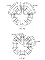
- Figure 4(a) shows, for example, a salient 8-pole rotor configuration for the winding.
- Each saliency comprises an iron core and a pole winding, which produces a magnetic field when direct current is injected into the pole winding.
- the poles will be either North (N) or South (S) polarity.
- the poles will be arranged in alternating polarities to give an even distribution of flux.
- Switching to a 4-pole configuration can be achieved by switching off half the pole windings and reversing the polarity on 2 of the remaining poles, as shown in Figure 4(b) .
- the amount of field current in the rotating field winding 60 can be increased, increasing the flux density in the iron cores of the active poles.
- the size of the poles is determined by the configuration with the lowest number of poles as the maximum allowable flux density is limited by the iron core material.
- the poles on the stationary armature winding 61 can be reconfigured by switching armature winding connectors to match the number of poles on the field winding 60.
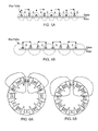
- Figures 5(a) and (b) show respectively 8-pole and 4-pole configurations of the armature winding achieved by switching the polarity of every second pole winding.
- the armature is represented as a linear armature and the pole windings are represented by single coils.
- the North (N) and South (S) poles are shown between the flux paths.
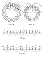
- Figure 6(a) shows a 6-pole configuration on such a 12 saliency pole rotor.
- Figure 7(a) shows an alternative 6-pole configuration on a 12 saliency pole rotor.
- FIG. 7(b) To switch to a 4-pole configuration, the polarities of six pole winding can be reversed, as shown in Figure 7(b) .
- this configuration uses all the available saliencies to form the poles.
- Figures 8(a) and (b) show respectively the corresponding 6-pole and 4-pole configurations of the stationary armature winding 61 achieved by placing, at the ends of the windings, switches or contactors that connect different wires within the armature together, to give the desired pole configuration.
- the rotating diode rectifier circuit 59 which produces a DC current, is connected via a control arrangement to the rotating field winding 60 of the main generator 52.
- the control arrangement includes a secondary exciter 62, a passive (e.g. diode-based) rectifier circuit 65, and a rotating switching circuit 66, which are all located on the shaft 53 between the main exciter 51 and the main generator.
- the secondary exciter is an inside-out machine, similar to the main exciter, in which the field winding 63 is located on the stator and the armature winding 64 on the rotor.
- the secondary exciter typically provides either single phase or 3-phase AC current on the rotor, which is rectified to DC by the rectifier circuit 65.
- the DC current is then fed to the switching circuit, which switches on or off and/or reverses the polarities of selected of the pole windings of the rotating field winding 60 to activate a different pole configuration in the main generator 52.
- the switching circuit 66 contains an arrangement of semiconductor-based switches.
- the conducting channels of the switches receive the output of the rotating rectifier 59.
- the secondary exciter 62 provides a gate current to the switches.
- Each switch either switches on or off individual pole windings of the field winding 60 or reverses the polarity of the pole windings, to give a desired new pole configuration on the rotor of the main generator 52.
- the switches are typically required to carry approximately 10 - 100A, they are generally high-powered devices such as power MOSFETs (metal-oxide-semiconductor field-effect transistors). Both depletion mode and enhancement mode MOSFETs can be used to switch from one pole configuration to another.
- the depletion mode MOSFETs conduct when there is no gate current and open when gate current is applied, while the enhancement mode MOSFETs open when there is no gate current and conduct when gate current is applied.
- D depletion mode
- E enhancement
- the depletion mode switches will conduct and the enhancement switches will open when no gate current is applied, i.e. the secondary exciter 62 is not providing power. When the secondary exciter is switched on it provides gate current, opening the depletion mode switches and closing the enhancement mode switches and thus reversing the polarity of the winding.
- This secondary exciter 62 generally has a lower rating than the main exciter 51, as it only needs to provide gate current to the switches.
- the control arrangement also includes a switch 67 which determines whether or not the field current provided by the voltage regulator circuit 56 is sent to the secondary exciter 62.
- the switch 67 is closed, the secondary exciter 62 is activated and gate current flows to the switches of the switching circuit 66.
- the switch 67 is open, the secondary exciter 62 is disabled and no gate current flows.
- the switch 67 can also be operatively connected (dashed line) to the the stationary armature winding 61 so that its poles are reconfigured to match the number of poles on the field winding 60 when the switch 67 is operated.
- the VFSG can switch poles on the main generator 52 during operation thus providing a wider rotational speed range or the shaft 53 while remaining within a predetermined electrical frequency range of the output AC current.
- the VFSG can provide and control its own reactive power and terminal voltage. As it does not require brushes and slip rings, it is suitable for high-speed applications and should not require high levels of maintenance.
- FIG 10 shows a schematic diagram of a VFSG according to a second embodiment of the present invention.
- the VFSG of the second embodiment includes a PMA 50, a main exciter 51 and a main generator 152.
- an alternative arrangement used by the second embodiment for changing the poles on the rotor of the main generator 152 without the use of brushes and slip rings is to have a second main exciter 151 operating at the same power level as the first main exciter 51, along with a second rotating diode rectifier 159 for the second main exciter.
- first and second winding formations can be provided by respectively a first set and a second set of pole windings on each saliency of the rotor of the main generator.
- control arrangement is simply a switch 167 which switches the output of the voltage regulator circuit 56 from one main exciter to the other.
- the switch 167 can also be operatively connected to the the stationary armature winding 161 so that its poles are reconfigured to match the number of poles on the field winding 160 when the switch 167 is operated.
- a drawback of this the second embodiment is that it tends to increase the overall size of the VFSG. Additionally, as there are two separate winding formations on the rotating field winding 160, undesirable voltage may be induced in the inactive formation.
- variable speed generator may also find use in other applications, particularly where it is desired to extend the rotational speed range of the shaft and to avoid the use of brushes and slip rings.
Landscapes
- Engineering & Computer Science (AREA)
- Power Engineering (AREA)
- Control Of Eletrric Generators (AREA)
Applications Claiming Priority (1)
| Application Number | Priority Date | Filing Date | Title |
|---|---|---|---|
| GBGB1107833.4A GB201107833D0 (en) | 2011-05-11 | 2011-05-11 | Variable speed generator |
Publications (3)
| Publication Number | Publication Date |
|---|---|
| EP2523318A2 true EP2523318A2 (fr) | 2012-11-14 |
| EP2523318A3 EP2523318A3 (fr) | 2018-02-07 |
| EP2523318B1 EP2523318B1 (fr) | 2018-12-26 |
Family
ID=44243917
Family Applications (1)
| Application Number | Title | Priority Date | Filing Date |
|---|---|---|---|
| EP12164543.6A Active EP2523318B1 (fr) | 2011-05-11 | 2012-04-18 | Générateur à vitesse variable |
Country Status (3)
| Country | Link |
|---|---|
| US (2) | US20120286516A1 (fr) |
| EP (1) | EP2523318B1 (fr) |
| GB (1) | GB201107833D0 (fr) |
Cited By (5)
| Publication number | Priority date | Publication date | Assignee | Title |
|---|---|---|---|---|
| CN103683474A (zh) * | 2013-12-13 | 2014-03-26 | 大唐黄岛发电有限责任公司 | 一种励磁功率柜冷却电源控制系统 |
| WO2014196981A1 (fr) | 2013-06-07 | 2014-12-11 | Ge Aviation Systems Llc | Réacteur à double flux équipé d'un générateur |
| EP3004565A4 (fr) * | 2013-06-06 | 2017-03-22 | GE Aviation Systems LLC | Ensemble moteur à réaction et procédé de génération d'électricité |
| FR3105885A1 (fr) * | 2019-12-26 | 2021-07-02 | Thales | Système d'entraînement électrique à deux étages |
| EP4117154A1 (fr) * | 2021-07-08 | 2023-01-11 | Hamilton Sundstrand Corporation | Enroulements d'excitateur pour un fonctionnement à grande vitesse |
Families Citing this family (19)
| Publication number | Priority date | Publication date | Assignee | Title |
|---|---|---|---|---|
| IL218451A0 (en) * | 2012-03-01 | 2012-04-30 | Birarov Ofer | Wind turbine |
| US9041232B2 (en) * | 2013-10-11 | 2015-05-26 | General Electric Company | Electric generator system |
| US9527600B2 (en) * | 2014-05-17 | 2016-12-27 | Hamilton Sundstrand Corporation | Ram air turbine generator assemblies |
| US9917490B2 (en) * | 2014-11-21 | 2018-03-13 | Hamilton Sundstrand Corporation | Tail cone generator with integral speed increasing gearbox |
| EP3035504B1 (fr) * | 2014-12-18 | 2017-07-26 | Rolls-Royce plc | Machines électriques |
| EP3104519B1 (fr) | 2015-06-11 | 2021-08-04 | Rolls-Royce North American Technologies, Inc. | Variation des quantités de pôles de moteur pour la réduction du bruit |
| US9548691B1 (en) * | 2015-06-24 | 2017-01-17 | Hamilton Sundstrand Corporation | Variable speed constant frequency power generator including permanent magnet exciter |
| US10186939B2 (en) * | 2016-03-01 | 2019-01-22 | Ford Global Technologies, Llc | Alternator with front end accessory drive |
| US11022004B2 (en) * | 2017-03-31 | 2021-06-01 | The Boeing Company | Engine shaft integrated motor |
| US10811936B2 (en) * | 2019-01-08 | 2020-10-20 | Hamilton Sundstrand Corporation | Generator systems |
| US10934880B1 (en) | 2019-09-04 | 2021-03-02 | The Boeing Company | Electrical generation from turbine engines |
| US11362567B2 (en) | 2020-01-16 | 2022-06-14 | The Boeing Company | Electrical power generation from turbine engines |
| US11193426B2 (en) | 2020-04-16 | 2021-12-07 | The Boeing Company | Electrically geared turbofan |
| US11325714B2 (en) | 2020-07-09 | 2022-05-10 | General Electric Company | Electric power system for a vehicle |
| US11444462B2 (en) | 2021-02-04 | 2022-09-13 | Honeywell International Inc. | Power generation system for wide speed range applications |
| US11845388B2 (en) | 2021-05-20 | 2023-12-19 | General Electric Company | AC electrical power system for a vehicle |
| US11750114B2 (en) | 2021-10-22 | 2023-09-05 | General Electric Company | Reduction of common mode emission of an electrical power converter |
| US11840148B2 (en) | 2022-02-15 | 2023-12-12 | Rolls-Royce Corporation/Rolls-Royce Singapore Pte. Ltd. | Hybrid aircraft having rectifier with integrated protection |
| US12095405B2 (en) * | 2022-02-15 | 2024-09-17 | Rolls-Royce Corporation | Fault tolerant turbo-generator system |
Family Cites Families (15)
| Publication number | Priority date | Publication date | Assignee | Title |
|---|---|---|---|---|
| US3200324A (en) * | 1960-02-29 | 1965-08-10 | Dudley W Wagner | Rotating electrical machine with multiple rotors in paired relation |
| AT332485B (de) | 1974-01-14 | 1976-09-27 | Siemens Ag | Bezuglich der betriebsfrequenz von 50 auf 60 hz umstellbare elektrische synchronmaschine |
| US4168459A (en) * | 1977-10-25 | 1979-09-18 | Precise Power Corporation | Non-interruptible power supply systems |
| US4467267A (en) | 1983-01-28 | 1984-08-21 | Sundstrand Corporation | Alternator excitation system |
| GB8316283D0 (en) | 1983-06-15 | 1983-07-20 | Ass Elect Ind | Multipolar excitation systems |
| US4663536A (en) * | 1985-03-04 | 1987-05-05 | Precise Power Corporation | A.C. motor-generator |
| JPH09149613A (ja) | 1995-11-24 | 1997-06-06 | Sawafuji Electric Co Ltd | エンジン発電機 |
| JP3775189B2 (ja) | 1999-12-28 | 2006-05-17 | 国産電機株式会社 | 内燃機関用スタータジェネレータ |
| US6906479B2 (en) * | 2002-08-06 | 2005-06-14 | Honeywell International, Inc. | Gas turbine engine starter generator with multiple windings on each exciter stator pole |
| US20040183308A1 (en) | 2003-03-17 | 2004-09-23 | Mingzhou Xu | Gas turbine engine starter generator that selectively changes the number of rotor poles |
| US7078826B2 (en) | 2004-08-17 | 2006-07-18 | Honeywell International, Inc. | Hybrid gas turbine engine starter-generator |
| US7388300B2 (en) * | 2006-09-20 | 2008-06-17 | Honeywell International, Inc. | Starter-generator operable with multiple variable frequencies and voltages |
| US8319481B2 (en) * | 2006-12-26 | 2012-11-27 | Hamilton Sundstrand Corporation | Pole shifting generator |
| US7969122B2 (en) * | 2007-11-14 | 2011-06-28 | Hamilton Sundstrand Corporation | Pole count changing generator |
| FR2952130B1 (fr) * | 2009-10-30 | 2018-09-07 | Safran Electrical & Power | Demarreur-generateur de turbomachine et procede pour sa commande. |
-
2011
- 2011-05-11 GB GBGB1107833.4A patent/GB201107833D0/en not_active Ceased
-
2012
- 2012-04-18 EP EP12164543.6A patent/EP2523318B1/fr active Active
- 2012-04-18 US US13/450,047 patent/US20120286516A1/en not_active Abandoned
-
2015
- 2015-08-20 US US14/831,433 patent/US9621090B2/en active Active
Non-Patent Citations (1)
| Title |
|---|
| None |
Cited By (8)
| Publication number | Priority date | Publication date | Assignee | Title |
|---|---|---|---|---|
| EP3004565A4 (fr) * | 2013-06-06 | 2017-03-22 | GE Aviation Systems LLC | Ensemble moteur à réaction et procédé de génération d'électricité |
| US10830085B2 (en) | 2013-06-06 | 2020-11-10 | Ge Aviation Systems Llc | Jet engine assembly and method for generating electricity |
| WO2014196981A1 (fr) | 2013-06-07 | 2014-12-11 | Ge Aviation Systems Llc | Réacteur à double flux équipé d'un générateur |
| EP3004564A4 (fr) * | 2013-06-07 | 2016-11-23 | Ge Aviat Systems Llc | Réacteur à double flux équipé d'un générateur |
| CN103683474A (zh) * | 2013-12-13 | 2014-03-26 | 大唐黄岛发电有限责任公司 | 一种励磁功率柜冷却电源控制系统 |
| FR3105885A1 (fr) * | 2019-12-26 | 2021-07-02 | Thales | Système d'entraînement électrique à deux étages |
| EP4117154A1 (fr) * | 2021-07-08 | 2023-01-11 | Hamilton Sundstrand Corporation | Enroulements d'excitateur pour un fonctionnement à grande vitesse |
| US11936252B2 (en) | 2021-07-08 | 2024-03-19 | Hamilton Sundstrand Corporation (HSC) | Exciter windings for wide speed operation |
Also Published As
| Publication number | Publication date |
|---|---|
| US20120286516A1 (en) | 2012-11-15 |
| EP2523318A3 (fr) | 2018-02-07 |
| EP2523318B1 (fr) | 2018-12-26 |
| US9621090B2 (en) | 2017-04-11 |
| GB201107833D0 (en) | 2011-06-22 |
| US20160079899A1 (en) | 2016-03-17 |
Similar Documents
| Publication | Publication Date | Title |
|---|---|---|
| US9621090B2 (en) | Variable speed generator having multiple exciter windings and selectable, independently activatable pole configurations | |
| US6906479B2 (en) | Gas turbine engine starter generator with multiple windings on each exciter stator pole | |
| US7880355B2 (en) | Electromagnetic variable transmission | |
| US6768278B2 (en) | Gas turbine engine starter generator with switchable exciter stator windings | |
| US4093869A (en) | Quadrature axis field brushless exciter | |
| KR940002926B1 (ko) | 시동 발전기 시스템 | |
| US8085004B2 (en) | Generator with quadrature AC excitation | |
| EP2654185B1 (fr) | Générateur à rotors multiples | |
| US7915869B2 (en) | Single stage starter/generator with rotor quadrature AC excitation | |
| US10830085B2 (en) | Jet engine assembly and method for generating electricity | |
| US8198872B2 (en) | Starter-generator with improved excitation | |
| US20080157622A1 (en) | Fault-tolerant permanent magnet machine | |
| CN108964532A (zh) | 三级式无刷同步电机分阶段式起动控制系统及方法 | |
| US7990115B2 (en) | High frequency generator without rotating diode rectifier | |
| CN108880363A (zh) | 三级式无刷同步电机异步起动控制方法及系统 | |
| CN202889138U (zh) | 一种并列式混合励磁无刷直流电机 | |
| CN102005875A (zh) | 并列结构的无刷无附加气隙混合励磁同步发电机 | |
| RU2356154C1 (ru) | Электрическая машина с двухпакетным индуктором (варианты) | |
| CN107565788A (zh) | 一种变极永磁直流起动发电机 | |
| Kamiev et al. | Feasibility of different excitation methods of synchronous generators in island operation | |
| CN113991895B (zh) | 一种分裂齿集成绕组起动发电机 |
Legal Events
| Date | Code | Title | Description |
|---|---|---|---|
| PUAI | Public reference made under article 153(3) epc to a published international application that has entered the european phase |
Free format text: ORIGINAL CODE: 0009012 |
|
| AK | Designated contracting states |
Kind code of ref document: A2 Designated state(s): AL AT BE BG CH CY CZ DE DK EE ES FI FR GB GR HR HU IE IS IT LI LT LU LV MC MK MT NL NO PL PT RO RS SE SI SK SM TR |
|
| AX | Request for extension of the european patent |
Extension state: BA ME |
|
| RAP1 | Party data changed (applicant data changed or rights of an application transferred) |
Owner name: ROLLS-ROYCE PLC |
|
| REG | Reference to a national code |
Ref country code: DE Ref legal event code: R079 Ref document number: 602012055036 Country of ref document: DE Free format text: PREVIOUS MAIN CLASS: H02K0019320000 Ipc: H02P0009480000 |
|
| PUAL | Search report despatched |
Free format text: ORIGINAL CODE: 0009013 |
|
| AK | Designated contracting states |
Kind code of ref document: A3 Designated state(s): AL AT BE BG CH CY CZ DE DK EE ES FI FR GB GR HR HU IE IS IT LI LT LU LV MC MK MT NL NO PL PT RO RS SE SI SK SM TR |
|
| AX | Request for extension of the european patent |
Extension state: BA ME |
|
| RIC1 | Information provided on ipc code assigned before grant |
Ipc: H02K 19/32 20060101ALI20180104BHEP Ipc: H02P 9/48 20060101AFI20180104BHEP Ipc: H02K 7/18 20060101ALI20180104BHEP |
|
| STAA | Information on the status of an ep patent application or granted ep patent |
Free format text: STATUS: REQUEST FOR EXAMINATION WAS MADE |
|
| 17P | Request for examination filed |
Effective date: 20180801 |
|
| RBV | Designated contracting states (corrected) |
Designated state(s): AL AT BE BG CH CY CZ DE DK EE ES FI FR GB GR HR HU IE IS IT LI LT LU LV MC MK MT NL NO PL PT RO RS SE SI SK SM TR |
|
| GRAP | Despatch of communication of intention to grant a patent |
Free format text: ORIGINAL CODE: EPIDOSNIGR1 |
|
| STAA | Information on the status of an ep patent application or granted ep patent |
Free format text: STATUS: GRANT OF PATENT IS INTENDED |
|
| INTG | Intention to grant announced |
Effective date: 20181008 |
|
| GRAS | Grant fee paid |
Free format text: ORIGINAL CODE: EPIDOSNIGR3 |
|
| GRAA | (expected) grant |
Free format text: ORIGINAL CODE: 0009210 |
|
| STAA | Information on the status of an ep patent application or granted ep patent |
Free format text: STATUS: THE PATENT HAS BEEN GRANTED |
|
| AK | Designated contracting states |
Kind code of ref document: B1 Designated state(s): AL AT BE BG CH CY CZ DE DK EE ES FI FR GB GR HR HU IE IS IT LI LT LU LV MC MK MT NL NO PL PT RO RS SE SI SK SM TR |
|
| REG | Reference to a national code |
Ref country code: GB Ref legal event code: FG4D |
|
| REG | Reference to a national code |
Ref country code: CH Ref legal event code: EP |
|
| REG | Reference to a national code |
Ref country code: AT Ref legal event code: REF Ref document number: 1082807 Country of ref document: AT Kind code of ref document: T Effective date: 20190115 |
|
| REG | Reference to a national code |
Ref country code: IE Ref legal event code: FG4D |
|
| REG | Reference to a national code |
Ref country code: DE Ref legal event code: R096 Ref document number: 602012055036 Country of ref document: DE |
|
| PG25 | Lapsed in a contracting state [announced via postgrant information from national office to epo] |
Ref country code: LT Free format text: LAPSE BECAUSE OF FAILURE TO SUBMIT A TRANSLATION OF THE DESCRIPTION OR TO PAY THE FEE WITHIN THE PRESCRIBED TIME-LIMIT Effective date: 20181226 Ref country code: HR Free format text: LAPSE BECAUSE OF FAILURE TO SUBMIT A TRANSLATION OF THE DESCRIPTION OR TO PAY THE FEE WITHIN THE PRESCRIBED TIME-LIMIT Effective date: 20181226 Ref country code: NO Free format text: LAPSE BECAUSE OF FAILURE TO SUBMIT A TRANSLATION OF THE DESCRIPTION OR TO PAY THE FEE WITHIN THE PRESCRIBED TIME-LIMIT Effective date: 20190326 Ref country code: LV Free format text: LAPSE BECAUSE OF FAILURE TO SUBMIT A TRANSLATION OF THE DESCRIPTION OR TO PAY THE FEE WITHIN THE PRESCRIBED TIME-LIMIT Effective date: 20181226 Ref country code: BG Free format text: LAPSE BECAUSE OF FAILURE TO SUBMIT A TRANSLATION OF THE DESCRIPTION OR TO PAY THE FEE WITHIN THE PRESCRIBED TIME-LIMIT Effective date: 20190326 Ref country code: FI Free format text: LAPSE BECAUSE OF FAILURE TO SUBMIT A TRANSLATION OF THE DESCRIPTION OR TO PAY THE FEE WITHIN THE PRESCRIBED TIME-LIMIT Effective date: 20181226 |
|
| REG | Reference to a national code |
Ref country code: NL Ref legal event code: MP Effective date: 20181226 |
|
| REG | Reference to a national code |
Ref country code: LT Ref legal event code: MG4D |
|
| PG25 | Lapsed in a contracting state [announced via postgrant information from national office to epo] |
Ref country code: GR Free format text: LAPSE BECAUSE OF FAILURE TO SUBMIT A TRANSLATION OF THE DESCRIPTION OR TO PAY THE FEE WITHIN THE PRESCRIBED TIME-LIMIT Effective date: 20190327 Ref country code: RS Free format text: LAPSE BECAUSE OF FAILURE TO SUBMIT A TRANSLATION OF THE DESCRIPTION OR TO PAY THE FEE WITHIN THE PRESCRIBED TIME-LIMIT Effective date: 20181226 Ref country code: SE Free format text: LAPSE BECAUSE OF FAILURE TO SUBMIT A TRANSLATION OF THE DESCRIPTION OR TO PAY THE FEE WITHIN THE PRESCRIBED TIME-LIMIT Effective date: 20181226 Ref country code: AL Free format text: LAPSE BECAUSE OF FAILURE TO SUBMIT A TRANSLATION OF THE DESCRIPTION OR TO PAY THE FEE WITHIN THE PRESCRIBED TIME-LIMIT Effective date: 20181226 |
|
| REG | Reference to a national code |
Ref country code: AT Ref legal event code: MK05 Ref document number: 1082807 Country of ref document: AT Kind code of ref document: T Effective date: 20181226 |
|
| PG25 | Lapsed in a contracting state [announced via postgrant information from national office to epo] |
Ref country code: NL Free format text: LAPSE BECAUSE OF FAILURE TO SUBMIT A TRANSLATION OF THE DESCRIPTION OR TO PAY THE FEE WITHIN THE PRESCRIBED TIME-LIMIT Effective date: 20181226 |
|
| PG25 | Lapsed in a contracting state [announced via postgrant information from national office to epo] |
Ref country code: PL Free format text: LAPSE BECAUSE OF FAILURE TO SUBMIT A TRANSLATION OF THE DESCRIPTION OR TO PAY THE FEE WITHIN THE PRESCRIBED TIME-LIMIT Effective date: 20181226 Ref country code: IT Free format text: LAPSE BECAUSE OF FAILURE TO SUBMIT A TRANSLATION OF THE DESCRIPTION OR TO PAY THE FEE WITHIN THE PRESCRIBED TIME-LIMIT Effective date: 20181226 Ref country code: PT Free format text: LAPSE BECAUSE OF FAILURE TO SUBMIT A TRANSLATION OF THE DESCRIPTION OR TO PAY THE FEE WITHIN THE PRESCRIBED TIME-LIMIT Effective date: 20190426 Ref country code: CZ Free format text: LAPSE BECAUSE OF FAILURE TO SUBMIT A TRANSLATION OF THE DESCRIPTION OR TO PAY THE FEE WITHIN THE PRESCRIBED TIME-LIMIT Effective date: 20181226 Ref country code: ES Free format text: LAPSE BECAUSE OF FAILURE TO SUBMIT A TRANSLATION OF THE DESCRIPTION OR TO PAY THE FEE WITHIN THE PRESCRIBED TIME-LIMIT Effective date: 20181226 |
|
| PG25 | Lapsed in a contracting state [announced via postgrant information from national office to epo] |
Ref country code: SM Free format text: LAPSE BECAUSE OF FAILURE TO SUBMIT A TRANSLATION OF THE DESCRIPTION OR TO PAY THE FEE WITHIN THE PRESCRIBED TIME-LIMIT Effective date: 20181226 Ref country code: EE Free format text: LAPSE BECAUSE OF FAILURE TO SUBMIT A TRANSLATION OF THE DESCRIPTION OR TO PAY THE FEE WITHIN THE PRESCRIBED TIME-LIMIT Effective date: 20181226 Ref country code: SK Free format text: LAPSE BECAUSE OF FAILURE TO SUBMIT A TRANSLATION OF THE DESCRIPTION OR TO PAY THE FEE WITHIN THE PRESCRIBED TIME-LIMIT Effective date: 20181226 Ref country code: RO Free format text: LAPSE BECAUSE OF FAILURE TO SUBMIT A TRANSLATION OF THE DESCRIPTION OR TO PAY THE FEE WITHIN THE PRESCRIBED TIME-LIMIT Effective date: 20181226 Ref country code: IS Free format text: LAPSE BECAUSE OF FAILURE TO SUBMIT A TRANSLATION OF THE DESCRIPTION OR TO PAY THE FEE WITHIN THE PRESCRIBED TIME-LIMIT Effective date: 20190426 |
|
| REG | Reference to a national code |
Ref country code: DE Ref legal event code: R097 Ref document number: 602012055036 Country of ref document: DE |
|
| PG25 | Lapsed in a contracting state [announced via postgrant information from national office to epo] |
Ref country code: DK Free format text: LAPSE BECAUSE OF FAILURE TO SUBMIT A TRANSLATION OF THE DESCRIPTION OR TO PAY THE FEE WITHIN THE PRESCRIBED TIME-LIMIT Effective date: 20181226 Ref country code: AT Free format text: LAPSE BECAUSE OF FAILURE TO SUBMIT A TRANSLATION OF THE DESCRIPTION OR TO PAY THE FEE WITHIN THE PRESCRIBED TIME-LIMIT Effective date: 20181226 |
|
| PLBE | No opposition filed within time limit |
Free format text: ORIGINAL CODE: 0009261 |
|
| STAA | Information on the status of an ep patent application or granted ep patent |
Free format text: STATUS: NO OPPOSITION FILED WITHIN TIME LIMIT |
|
| REG | Reference to a national code |
Ref country code: CH Ref legal event code: PL |
|
| 26N | No opposition filed |
Effective date: 20190927 |
|
| REG | Reference to a national code |
Ref country code: BE Ref legal event code: MM Effective date: 20190430 |
|
| PG25 | Lapsed in a contracting state [announced via postgrant information from national office to epo] |
Ref country code: LU Free format text: LAPSE BECAUSE OF NON-PAYMENT OF DUE FEES Effective date: 20190418 Ref country code: MC Free format text: LAPSE BECAUSE OF FAILURE TO SUBMIT A TRANSLATION OF THE DESCRIPTION OR TO PAY THE FEE WITHIN THE PRESCRIBED TIME-LIMIT Effective date: 20181226 |
|
| PG25 | Lapsed in a contracting state [announced via postgrant information from national office to epo] |
Ref country code: LI Free format text: LAPSE BECAUSE OF NON-PAYMENT OF DUE FEES Effective date: 20190430 Ref country code: CH Free format text: LAPSE BECAUSE OF NON-PAYMENT OF DUE FEES Effective date: 20190430 |
|
| PG25 | Lapsed in a contracting state [announced via postgrant information from national office to epo] |
Ref country code: SI Free format text: LAPSE BECAUSE OF FAILURE TO SUBMIT A TRANSLATION OF THE DESCRIPTION OR TO PAY THE FEE WITHIN THE PRESCRIBED TIME-LIMIT Effective date: 20181226 Ref country code: BE Free format text: LAPSE BECAUSE OF NON-PAYMENT OF DUE FEES Effective date: 20190430 |
|
| PG25 | Lapsed in a contracting state [announced via postgrant information from national office to epo] |
Ref country code: TR Free format text: LAPSE BECAUSE OF FAILURE TO SUBMIT A TRANSLATION OF THE DESCRIPTION OR TO PAY THE FEE WITHIN THE PRESCRIBED TIME-LIMIT Effective date: 20181226 |
|
| PG25 | Lapsed in a contracting state [announced via postgrant information from national office to epo] |
Ref country code: IE Free format text: LAPSE BECAUSE OF NON-PAYMENT OF DUE FEES Effective date: 20190418 |
|
| PG25 | Lapsed in a contracting state [announced via postgrant information from national office to epo] |
Ref country code: CY Free format text: LAPSE BECAUSE OF FAILURE TO SUBMIT A TRANSLATION OF THE DESCRIPTION OR TO PAY THE FEE WITHIN THE PRESCRIBED TIME-LIMIT Effective date: 20181226 |
|
| PG25 | Lapsed in a contracting state [announced via postgrant information from national office to epo] |
Ref country code: MT Free format text: LAPSE BECAUSE OF FAILURE TO SUBMIT A TRANSLATION OF THE DESCRIPTION OR TO PAY THE FEE WITHIN THE PRESCRIBED TIME-LIMIT Effective date: 20181226 Ref country code: HU Free format text: LAPSE BECAUSE OF FAILURE TO SUBMIT A TRANSLATION OF THE DESCRIPTION OR TO PAY THE FEE WITHIN THE PRESCRIBED TIME-LIMIT; INVALID AB INITIO Effective date: 20120418 |
|
| PG25 | Lapsed in a contracting state [announced via postgrant information from national office to epo] |
Ref country code: MK Free format text: LAPSE BECAUSE OF FAILURE TO SUBMIT A TRANSLATION OF THE DESCRIPTION OR TO PAY THE FEE WITHIN THE PRESCRIBED TIME-LIMIT Effective date: 20181226 |
|
| P01 | Opt-out of the competence of the unified patent court (upc) registered |
Effective date: 20230528 |
|
| PGFP | Annual fee paid to national office [announced via postgrant information from national office to epo] |
Ref country code: GB Payment date: 20240423 Year of fee payment: 13 |
|
| PGFP | Annual fee paid to national office [announced via postgrant information from national office to epo] |
Ref country code: DE Payment date: 20240429 Year of fee payment: 13 |
|
| PGFP | Annual fee paid to national office [announced via postgrant information from national office to epo] |
Ref country code: FR Payment date: 20240430 Year of fee payment: 13 |