EP2523011B1 - Phased array MR RF coil which is not visible in X-ray image - Google Patents
Phased array MR RF coil which is not visible in X-ray image Download PDFInfo
- Publication number
- EP2523011B1 EP2523011B1 EP12167077.2A EP12167077A EP2523011B1 EP 2523011 B1 EP2523011 B1 EP 2523011B1 EP 12167077 A EP12167077 A EP 12167077A EP 2523011 B1 EP2523011 B1 EP 2523011B1
- Authority
- EP
- European Patent Office
- Prior art keywords
- coil
- support
- attenuation
- radiation
- loops
- Prior art date
- Legal status (The legal status is an assumption and is not a legal conclusion. Google has not performed a legal analysis and makes no representation as to the accuracy of the status listed.)
- Active
Links
Images



Classifications
-
- G—PHYSICS
- G01—MEASURING; TESTING
- G01R—MEASURING ELECTRIC VARIABLES; MEASURING MAGNETIC VARIABLES
- G01R33/00—Arrangements or instruments for measuring magnetic variables
- G01R33/20—Arrangements or instruments for measuring magnetic variables involving magnetic resonance
- G01R33/28—Details of apparatus provided for in groups G01R33/44 - G01R33/64
- G01R33/32—Excitation or detection systems, e.g. using radio frequency signals
- G01R33/34—Constructional details, e.g. resonators, specially adapted to MR
- G01R33/341—Constructional details, e.g. resonators, specially adapted to MR comprising surface coils
- G01R33/3415—Constructional details, e.g. resonators, specially adapted to MR comprising surface coils comprising arrays of sub-coils, i.e. phased-array coils with flexible receiver channels
-
- A—HUMAN NECESSITIES
- A61—MEDICAL OR VETERINARY SCIENCE; HYGIENE
- A61B—DIAGNOSIS; SURGERY; IDENTIFICATION
- A61B5/00—Measuring for diagnostic purposes; Identification of persons
- A61B5/05—Detecting, measuring or recording for diagnosis by means of electric currents or magnetic fields; Measuring using microwaves or radio waves
- A61B5/055—Detecting, measuring or recording for diagnosis by means of electric currents or magnetic fields; Measuring using microwaves or radio waves involving electronic [EMR] or nuclear [NMR] magnetic resonance, e.g. magnetic resonance imaging
-
- A—HUMAN NECESSITIES
- A61—MEDICAL OR VETERINARY SCIENCE; HYGIENE
- A61B—DIAGNOSIS; SURGERY; IDENTIFICATION
- A61B5/00—Measuring for diagnostic purposes; Identification of persons
- A61B5/70—Means for positioning the patient in relation to the detecting, measuring or recording means
- A61B5/704—Tables
-
- A—HUMAN NECESSITIES
- A61—MEDICAL OR VETERINARY SCIENCE; HYGIENE
- A61B—DIAGNOSIS; SURGERY; IDENTIFICATION
- A61B6/00—Apparatus or devices for radiation diagnosis; Apparatus or devices for radiation diagnosis combined with radiation therapy equipment
- A61B6/04—Positioning of patients; Tiltable beds or the like
- A61B6/0407—Supports, e.g. tables or beds, for the body or parts of the body
-
- A—HUMAN NECESSITIES
- A61—MEDICAL OR VETERINARY SCIENCE; HYGIENE
- A61B—DIAGNOSIS; SURGERY; IDENTIFICATION
- A61B6/00—Apparatus or devices for radiation diagnosis; Apparatus or devices for radiation diagnosis combined with radiation therapy equipment
- A61B6/44—Constructional features of apparatus for radiation diagnosis
- A61B6/4417—Constructional features of apparatus for radiation diagnosis related to combined acquisition of different diagnostic modalities
-
- A—HUMAN NECESSITIES
- A61—MEDICAL OR VETERINARY SCIENCE; HYGIENE
- A61B—DIAGNOSIS; SURGERY; IDENTIFICATION
- A61B5/00—Measuring for diagnostic purposes; Identification of persons
- A61B5/0033—Features or image-related aspects of imaging apparatus, e.g. for MRI, optical tomography or impedance tomography apparatus; Arrangements of imaging apparatus in a room
- A61B5/0035—Features or image-related aspects of imaging apparatus, e.g. for MRI, optical tomography or impedance tomography apparatus; Arrangements of imaging apparatus in a room adapted for acquisition of images from more than one imaging mode, e.g. combining MRI and optical tomography
-
- A—HUMAN NECESSITIES
- A61—MEDICAL OR VETERINARY SCIENCE; HYGIENE
- A61B—DIAGNOSIS; SURGERY; IDENTIFICATION
- A61B6/00—Apparatus or devices for radiation diagnosis; Apparatus or devices for radiation diagnosis combined with radiation therapy equipment
- A61B6/52—Devices using data or image processing specially adapted for radiation diagnosis
- A61B6/5211—Devices using data or image processing specially adapted for radiation diagnosis involving processing of medical diagnostic data
- A61B6/5229—Devices using data or image processing specially adapted for radiation diagnosis involving processing of medical diagnostic data combining image data of a patient, e.g. combining a functional image with an anatomical image
- A61B6/5247—Devices using data or image processing specially adapted for radiation diagnosis involving processing of medical diagnostic data combining image data of a patient, e.g. combining a functional image with an anatomical image combining images from an ionising-radiation diagnostic technique and a non-ionising radiation diagnostic technique, e.g. X-ray and ultrasound
-
- A—HUMAN NECESSITIES
- A61—MEDICAL OR VETERINARY SCIENCE; HYGIENE
- A61N—ELECTROTHERAPY; MAGNETOTHERAPY; RADIATION THERAPY; ULTRASOUND THERAPY
- A61N5/00—Radiation therapy
- A61N5/10—X-ray therapy; Gamma-ray therapy; Particle-irradiation therapy
- A61N5/1048—Monitoring, verifying, controlling systems and methods
- A61N5/1049—Monitoring, verifying, controlling systems and methods for verifying the position of the patient with respect to the radiation beam
- A61N2005/1055—Monitoring, verifying, controlling systems and methods for verifying the position of the patient with respect to the radiation beam using magnetic resonance imaging [MRI]
-
- G—PHYSICS
- G01—MEASURING; TESTING
- G01R—MEASURING ELECTRIC VARIABLES; MEASURING MAGNETIC VARIABLES
- G01R33/00—Arrangements or instruments for measuring magnetic variables
- G01R33/20—Arrangements or instruments for measuring magnetic variables involving magnetic resonance
- G01R33/28—Details of apparatus provided for in groups G01R33/44 - G01R33/64
- G01R33/32—Excitation or detection systems, e.g. using radio frequency signals
- G01R33/36—Electrical details, e.g. matching or coupling of the coil to the receiver
- G01R33/3642—Mutual coupling or decoupling of multiple coils, e.g. decoupling of a receive coil from a transmission coil, or intentional coupling of RF coils, e.g. for RF magnetic field amplification
- G01R33/365—Decoupling of multiple RF coils wherein the multiple RF coils have the same function in MR, e.g. decoupling of a receive coil from another receive coil in a receive coil array, decoupling of a transmission coil from another transmission coil in a transmission coil array
-
- G—PHYSICS
- G01—MEASURING; TESTING
- G01R—MEASURING ELECTRIC VARIABLES; MEASURING MAGNETIC VARIABLES
- G01R33/00—Arrangements or instruments for measuring magnetic variables
- G01R33/20—Arrangements or instruments for measuring magnetic variables involving magnetic resonance
- G01R33/44—Arrangements or instruments for measuring magnetic variables involving magnetic resonance using nuclear magnetic resonance [NMR]
- G01R33/48—NMR imaging systems
- G01R33/4808—Multimodal MR, e.g. MR combined with positron emission tomography [PET], MR combined with ultrasound or MR combined with computed tomography [CT]
- G01R33/4812—MR combined with X-ray or computed tomography [CT]
Definitions
- This invention relates to a phased array RF coil formed of a series of separate coil elements or individual loops for use in magnetic resonance imaging which can be used to obtain MR images of a body part of a patient and can remain in place during electromagnetic radiation imaging of the body part without interfering with the radiation image.
- the coil array can be used for receive functions, transmit functions or can carry out both functions.
- Magnetic resonance imaging is commonly employed for medical imaging.
- MRI Magnetic resonance imaging
- X-Ray radiation
- radiation imaging have both been used in a number of prior situations.
- Such systems provide significant advantages compared to single modality systems for obtaining information of the patient.
- the patient may need to be moved or transferred from one system to another system. Such transfers can be difficult and time-consuming, and they can compromise results by complicating image registration.
- the MRI in combination with a radiotherapy accelerator has been used.
- the X-Rays must be transmitted through the RF coil of the MR imaging system which remains in place during the radiotherapy.
- the RF coils of the MRI system are in the radiation path, they do not cause enough absorption to significantly degrade therapy or require a higher dose for imaging.
- the RF coils may have an equivalent AI thickness of about 2.3 mm, which is sufficiently low for the therapy to be carried out without interference from the coil and low enough not to affect the optimal dose of X-Ray radiation.
- MRI magnetic resonance imaging
- X-Ray imaging causes unique problems. Specifically, if a conventional surface MRI Receive Coil is placed in the imaging path of a X-Ray system, the coil will be visible in the image and will cause artifacts or edges or components of the receive coil may cover important features in the X-Ray image which are required to be seen by the surgeon. For this reason, when MRI is performed in combination with radiation imaging, all coils of the MRI system, including the RF coils, are typically disposed out of or removed from the radiation path so as to be outside the field of view.
- MRI performance can be undesirably degraded by a requirement to place the MRI RF coils outside the field of view of a radiation imaging system.
- surface RF coils are often placed directly on a subject being imaged for maximum MRI image quality.
- Such a surface coil is in the field of view of any radiation imaging system that is directed to the same part of the subject as the MRI system.
- conventional combined MRI and radiation imaging can require an undesirable choice among accepting reduced MRI image quality by placing the RF coils out of the radiation system field of view, accepting RF coil artifacts in the radiation images by placing the RF coils in the radiation system field of view, or by moving the MRI RF coils to one position for MRI imaging and to another position out of the field of view for radiation imaging.
- US patent 7,394,254 issued July 1st 2008 discloses using aluminum for the RF coils to render them "transparent" to X-Ray. More particularly, the patent discloses an arrangement in which improved compatibility of MRI with radiation imaging is provided by MRI RF coils having transmissive coil sections.
- the transmissive coil sections are substantially transparent to the penetrating radiation employed by the radiation imaging system.
- the transmissive coil sections can be disposed in a field of view of the radiation imaging system without introducing artifacts into the radiation images.
- Transparency to penetrating radiation can be achieved by substantially including only low atomic number (i.e., Z ⁇ 29) elements in the transmissive coil sections.
- the transmissive coil sections are fabricated substantially from aluminum.
- US patent application 5 491 415 A discloses an RF phased array coil according to the preamble of claim 1.
- an RF phased array coil for use in an MR imaging system for generating an MR image of a subject for use in a radiation imaging system for generating a radiation image of said subject using penetrating electromagnetic radiation
- the phased array coil comprising conductive traces; a support defined by at least one substrate sheet;and a plurality of coil loops formed by said conductive traces mounted on said support; one of said coil loops overlapping another one of the coil loops so that a leg of said one coil loop lies adjacent to a leg of said other coil loop with two sections at opposite ends of the leg of said one coil loop crossing two corresponding sections at opposite ends of the leg of said other coil loop;
- each of the coil loops has a thickness along the full length thereof, with the exception of crossing sections and corresponding sections, which is constant.
- said one of said coil loops is arranged on a first surface of the substrate sheet and said other of the coil loops is arranged on a second opposed surface of the substrate sheet.
- the support comprises first and second overlying laminated substrate sheets and wherein said one of said coil loops is arranged on a first surface of the first substrate sheet and said other of the coil loops is arranged on a second opposed surface of the first substrate sheet so as to be located between the first and second substrate sheets.
- a third of the coil loops which is located on a second opposed surface of the second substrate sheet and wherein the third coil loop is overlapped with said one and said other of the individual coil loops.
- the support is formed from common material.
- the support is formed from a base material and an additional material different from the base material is added to the support where the base material and the additional material are preferably laminated to form a common structure.
- the support is flexible.
- the conductive traces are formed of copper.
- the conductive traces are preferably formed of aluminum to reduce the attenuation but the same concepts can be used where the conductive traces are formed of copper.
- the support substrate sheet is formed of fiber reinforced resin such as FR-4.
- the trace is reduced in thickness to approximately one-half the metal thickness giving a uniform x-ray aluminum equivalence across the region.
- the technique can be applied to any material with an atomic number less than 30.
- the coils traces are also interleaved from the front and the back of the substrate to maintain the same X-ray aluminum equivalency.
- the non-conductive material of the support board is arranged relative to the conductive traces such that the attenuation of the penetrating electromagnetic radiation of substantially the whole of the RF coil located within the field of view is substantially constant throughout the field of view.
- the attenuation may however be points or areas where the attenuation is different and an alternative system is used to remove these points or areas from the image. It will be appreciated that such attenuation is not invisible in the image but is instead visible in the sense that it is sufficient to affect the image so that its presence can be determined.
- the intention is that the attenuation is constant or homogeneous so that there is no visible artefact within the image and the presence of the RF coil within the image does not affect the changes of image intensity at the various locations within the image which are caused by the differences in attenuation caused by the part being imaged.
- the support board is formed from common material and wherein the thickness of the common material is varied so that the attenuation of the penetrating electromagnetic radiation of substantially the whole of the RF coil located within the field of view is substantially constant throughout the field of view.
- the support board is formed from a base material and an additional material different from the base material is added to the support board.
- the material can be machined to provide the required thicknesses as determined by analyzing the difference in attenuation caused by the materials themselves relative to the copper traces and calculating the required thickness.
- Materials can be selected for the additional material or for the board itself which have a very high attenuation so that the thickness of the material is not significantly different from the copper traces.
- the support board Conventional techniques and materials for manufacturing the support board can be used including printing the traces or etching the traces as required.
- traces is not intended to limit the conductors to any particular method of formation of the conductors on the support board.
- the base material and the additional material are laminated to form a common structure.
- the conductive traces are continuous throughout the field of view so as to have a constant thickness and therefore attenuation.
- Many techniques are available for forming such continuous traces with out the necessity for joints which may double the thickness at certain locations or may require connecting material such as solder.
- the conductive traces include no solder within the field of view.
- connector wires from the conductive traces within the field of view so that the connector wires such as coaxial connectors, wires and rods which connect from the traces to the pre-amplifier or other location are located outside the field of view.
- the tuning capacitors required for such a coil In many cases it is necessary to locate the tuning capacitors required for such a coil to be located within the field of view and preferably it is arranged such that the capacitor has an attenuation of the penetrating electromagnetic radiation which is substantially equal to the attenuation of the conductive traces.
- the capacitor is formed from conductive traces with a dielectric material between the traces to define the required capacitance.
- the fuse is formed from conductive traces.
- the support board includes no mechanical mounting and support structures within the field of view.
- the support board may be flexible.
- the location of the diode in the field of view is arranged to be constant and the image of the diode or other element in the radiation image is removed by software image analysis.
- the conductive traces are formed of copper but other similarly conductive materials can be used instead of aluminum which is effectively transparent to the X-Rays but is generally unsuitable for RF coil manufacture.
- the support board can be formed of any suitable non-conductive material which is MR compatible and has an attenuation to X-Rays which is less than or around that of copper such as FR-4 fibreglass circuit board.
- Figure 1 an arrangement for carrying out Magnetic Resonance Imaging and X-Ray imaging of a patient while the patient remains stationary on a patient support table.
- the arrangement provides a room 1 in which is mounted a patient support table 10 with doors 2 at one side of the room for entry into the room of the magnet 3 of an MR imaging system from a magnet bay 1A.
- the room contains an X-Ray imaging system 4 mounted on rails 5 and includes an X-Ray transmitter 6 and receiver 7 mounted on a C-shaped support 8.
- the X-Ray system is of a conventional construction commercially available from a manufacturer such as Siemens.
- the table 10 described and illustrated herein is used in an arrangement where the patient remains in position on the table while imaging is effected using MRI and X-Ray.
- the X-Ray system 4 which co-operates with the moving magnet described above such that the patient can be imaged by either modality on the same table.
- the patient does not move and at least one of the RF coils remains in place.
- the MR is a high-field (e.g. 1.5T or 3T or more) magnet that moves on overhead rails between the two or more rooms as described above.
- one or more of these rooms contains an X-Ray system, either a single-plane or a biplane.
- the examination room functions as a conventional X-Ray lab and can be used with conventional equipment. In particular, X-Ray guided interventions may be performed.
- the arrangement may be used in a typical three room configuration with the Angiography Room (AR) on the left, a Diagnostic Room (DR) in the middle, and an Operating Room on the right.
- AR Angiography Room
- DR Diagnostic Room
- Operating Room on the right.
- the magnet moves on overhead rails between the rooms and can image in each.
- the X-Ray equipment When MR imaging is required, the X-Ray equipment is safely stowed, the doors open, and the magnet is brought into the room over the patient on the table.
- the RF shield encompasses the AR so all the equipment in the X-Ray examination room is made RF-quiet. MR imaging can then be performed. Afterwards, the magnet is removed from the room, the doors closed, and the X-Ray equipment is returned to its working position.
- the MR scanner is used to provide information complementary to that obtained using X-Ray. It can be used, for example, to perform a baseline assessment prior to intervention as well as to perform a post-intervention assessment. Such an assessment may include perfusion and viability studies of, for example, the heart or of the brain.
- a floor-mounted C-arm stand may be moved on floor rails, floor turntable, or a boom mounted on the floor or wall.
- a ceiling-mounted C-arm stand may be moved using extended rails to park it at the foot end of the table, by mounting the stand rails on a platform suspended from the movable magnet rails, or by fixing the stand rails on a platform with a telescopic arm to move them laterally.
- Using a solution to move a floor-mounted stand together with a mover for a ceiling mounted stand provides a mechanism to move a biplane system.
- the mover can provide a mounting position of the single plane or biplane at some non-zero angle to the MR rails, e.g., 90 degrees.
- the Patient Handling System or support table is shown in Figure 2 as indicated generally at 10.
- the patient support table includes a base 11 of a conventional construction which allows the base to move a patient support portion 12 to required locations in height and in orientation. Suitable drive mechanisms and couplings are known in the art and thus are not required to be described herein.
- the patient support portion At the top of the base 11 is mounted the patient support portion in the form of a generally planar body 12 formed of a fiber reinforced plastics material so as to define a surface area sufficient for supporting the patient while lying on the patient support portion.
- an anterior chest coil 31 is arranged to be placed on top of the chest of the patient when in place for imaging on the mattress and also the posterior coil 32 is arranged to be place behind the patient.
- the posterior coil 32 is arranged to be place behind the patient.
- coils are placed above and below the head of the patient.
- the imaging system may be a simple linear X-Ray system or more preferably is a bi-planar rotating system of the type illustrated which takes multiple images around the patient.
- the apparatus for use in imaging of a part of a patient as shown in Figure 1 includes the radiation imaging system 4 for generating a radiation image of a subject in the field of view using penetrating electromagnetic radiation and the magnetic resonance imaging system for generating an image of the subject including the magnet 3 and the RF coils 31, 32.
- FIG. 3 and 4 A schematic illustration of the RF coil 32 is shown in Figures 3 and 4 and is arranged to remain in place during the radiation imaging using the X-Ray transmitter 50 and receiver 51 shown only schematically.
- the RF coil includes a support board 33 having side edges 34 and the imaging system 4 defines a field of view 35 within the area of the board which can be seen in the X-Ray image with portions of the board outside the field of view being outside the image.
- the circuitry of the coil includes conductive traces 36, capacitors 37, a fuse 41, a diode 38, a connecting wire 39, and a pre-amplifier 40. All of these elements are conventional in general construction and are well known to persons skilled in the art of coil design so that detailed explanation is not required here.
- the conductive traces of the RF coil are arranged of a conductive material and typically copper which has a thickness T3 of at least 0.0018 cm (0.0007 inch) and preferably in the range 0.0036 cm to 0.0107 cm (0.0014 inch to 0.0042 inch) which is effective to receive the RF signals from the MR imaging system.
- Such traces typically cause an attenuation of the penetrating electromagnetic radiation which is clearly visible in the radiation image as compared with a uniform thickness support board material.
- the support board is formed of a non-conductive material in the field of view which has a thickness T1 at locations on the board spaced from the traces selected such that an attenuation of the penetrating electromagnetic radiation at those locations is substantially equal to the attenuation at the conductive traces.
- the attenuation of the board material at thickness T1 is arranged so that it is equal to the sum of the attenuation caused by the thickness T3 of the trace and thickness T2 of the board at the trace. In this way the attenuation of the penetrating electromagnetic radiation of substantially the whole of the RF coil located within the field of view is substantially constant throughout the field of view.
- the traces are shown in Figure 4 recessed into shallow areas of the board, the traces can be applied on top of the flat board and the variable thickness of the board applied at the rear.
- the board may be flat by filling recesses with a material which is transparent to X-Ray and thus does not affect the attenuation.
- Figure 5 is shown an alternative arrangement in which the board is formed of a base material 33A and an additional material 33B is added to the support board at areas separate from the traces, which material is non-conductive and has an attenuation factor that is it is not transparent to X-Ray and is different from the base material 33A.
- the base material and the additional material are laminated to form a common structure and the recesses may be filled by additional transparent material.
- the conductive traces are arranged to be continuous throughout the field of view so as to have a constant attenuation. That is the conductive traces include no joints and therefore no solder within the field of view. Instead the traces are printed or otherwise applied as a constant continuous strip. Alternatively the traces are formed by etching away unwanted material from a continuous layer on the board leaving traces which are continuous and without joints.
- the capacitors 37 and the fuse 41 for the coil are in most cases necessarily located within the field of view 35 and these are therefore arranged so that the attenuation of the penetrating electromagnetic radiation is substantially equal to the attenuation of the board at the conductive traces.
- the capacitor and the fuse is itself formed from conductive traces which are designed and laid out on the board with the required amount of conductive material and the dielectric material to provide the required characteristics and values. The design of such components from conductive traces is known and within the skill of a person skilled in this art.
- the support board includes mechanical mounting and support structures 42 for connection of the board to necessary elements but these are designed and arranged so that they are outside the field of view so that the board is generally constant and continuous and there are no mechanical structures within the field of view.
- the necessary diode 38 is designed and arranged on the traces so that it is located outside field of view.
- the diode or other necessary element is located within the field of view where the element has an attenuation different from the conductive traces and of a construction and high attenuation factor such that it cannot reasonably be compensated for by building the remainder of the board up to this high attenuation factor.
- the location of the element in the field of view is constant and the image of the element in the radiation image is removed by software image analysis at the X-Ray receiver system 51.
- the RF phased array coil shown in Figure 6 includes a support 60 defined by a single substrate sheet or as shown in Figure 7 two substrate sheets S1 and S2.
- the individual coil loops 61 and 62 are overlapped with each other so that a leg 62A of loop 62 lies adjacent to a leg 61A of loop 61 with two sections 62B and 62C at ends of the leg 62A of loop 62 crossing two corresponding sections 61 B and 61C at ends of the leg 61A of coil loop 61.
- the width of the trace is reduced from a width W1 at the remainder of the trace to a width W2 at the crossing. This is a known technique to reduce capacitive coupling between the loops for purposes of assisting in de-coupling the loops.
- loop 63 overlaps in symmetrical manner loops 61 and 62 to form leg 63D1 which lies alongside leg 61 D and leg 63D2 which lies alongside leg 62D.
- Each leg has crossing points at its ends.
- the legs 63D1 and 63D2 cross leg 62A at crossing 63D4 and leg 61A at crossing 63D5 forming a short section 63D3 between the crossings.
- the crossing section 63D4 crosses a corresponding section 62A4 of the leg 61.
- a symmetrical arrangement is made between coils 63, 64 and 65.
- each of the corresponding sections 62A4 and 61A4 has a thickness T2 in a direction at right angles to the substrate S1, S2 which is less than the thickness T1 of the legs 63D1, 63D2, 63D3, 62A and 61A.
- each of the crossing sections and each of the corresponding sections has the thickness T2 equal to one half of thickness T1 and each of the individual coil loops 61, 62 and 63 has the constant thickness T1 along the full length thereof, with the exception of crossing sections and corresponding sections.
- individual coil loop 62 is arranged or printed on the first or top (in the orientation shown) surface S1T of the substrate sheet S1 and the individual coil loop 63 is arranged on a second opposed surface S1 B of the substrate sheet S1.
- the substrate is formed by only the single sheet S1.
- the second sheet S2 is provided on the bottom of the loop 63 so that its top surface S2T engages the loop 63 with the loop 62 on the bottom surface S2B of the sheet S2.
- the conductive traces 61, 62 and 63 of the RF coil arranged of a conductive material have a thickness such that the traces cause an attenuation of the penetrating electromagnetic radiation which is visible in the radiation image and, as explained above in relation to the cited prior application, the support substrate includes non-conductive material in the field of view which has a thickness selected such that an attenuation of the penetrating electromagnetic radiation at locations on the substrate sheet spaced from the traces is substantially equal to the attenuation at locations on the substrate sheet at the conductive traces.
- the overlapping sections are arranged with the thickness T2 over a length which matches almost so that the summation of the thickness of the loops measured over the whole coil surface is T!.
- this can be matched with a thickness of the substrate or a material applied to eh substrate to provide a constant aluminum equivalent value over the whole coil structure within the intended field of view of the X-ray system.
- the support substrate sheet can be formed of a single material of different thicknesses.
- the support can be formed from a base material and an additional material different from the base material is added to the support substrate sheet so that the attenuation of the penetrating electromagnetic radiation of substantially the whole of the RF coil located within the field of view is substantially constant throughout the field of view.
- the support formed by substrate sheets S1 and S2 is preferably flexible but this is not essential.
- the conductive traces can be formed of copper or aluminum or other suitable materials well known to a person skilled in this art.
- the support substrate sheets S1 and S2 are formed of fiber reinforced resin such as FR-4.
Landscapes
- Health & Medical Sciences (AREA)
- Life Sciences & Earth Sciences (AREA)
- Physics & Mathematics (AREA)
- Engineering & Computer Science (AREA)
- Medical Informatics (AREA)
- Surgery (AREA)
- Veterinary Medicine (AREA)
- Heart & Thoracic Surgery (AREA)
- Pathology (AREA)
- Molecular Biology (AREA)
- Biophysics (AREA)
- Animal Behavior & Ethology (AREA)
- General Health & Medical Sciences (AREA)
- Public Health (AREA)
- Biomedical Technology (AREA)
- Nuclear Medicine, Radiotherapy & Molecular Imaging (AREA)
- High Energy & Nuclear Physics (AREA)
- Radiology & Medical Imaging (AREA)
- Optics & Photonics (AREA)
- Condensed Matter Physics & Semiconductors (AREA)
- General Physics & Mathematics (AREA)
- Magnetic Resonance Imaging Apparatus (AREA)
- Apparatus For Radiation Diagnosis (AREA)
Description
- This invention relates to a phased array RF coil formed of a series of separate coil elements or individual loops for use in magnetic resonance imaging which can be used to obtain MR images of a body part of a patient and can remain in place during electromagnetic radiation imaging of the body part without interfering with the radiation image. The coil array can be used for receive functions, transmit functions or can carry out both functions.
- Magnetic resonance imaging (MRI) is commonly employed for medical imaging. In addition, combined use of MRI with radiation (X-Ray) therapy and with radiation imaging have both been used in a number of prior situations. Such systems provide significant advantages compared to single modality systems for obtaining information of the patient. However in such prior dual imaging systems, the patient may need to be moved or transferred from one system to another system. Such transfers can be difficult and time-consuming, and they can compromise results by complicating image registration.
- MRI in combination with a radiotherapy accelerator has been used. Thus the X-Rays must be transmitted through the RF coil of the MR imaging system which remains in place during the radiotherapy. Although the RF coils of the MRI system are in the radiation path, they do not cause enough absorption to significantly degrade therapy or require a higher dose for imaging. For example the RF coils may have an equivalent AI thickness of about 2.3 mm, which is sufficiently low for the therapy to be carried out without interference from the coil and low enough not to affect the optimal dose of X-Ray radiation.
- The combination of MRI with radiation imaging or more specifically X-Ray imaging causes unique problems. Specifically, if a conventional surface MRI Receive Coil is placed in the imaging path of a X-Ray system, the coil will be visible in the image and will cause artifacts or edges or components of the receive coil may cover important features in the X-Ray image which are required to be seen by the surgeon. For this reason, when MRI is performed in combination with radiation imaging, all coils of the MRI system, including the RF coils, are typically disposed out of or removed from the radiation path so as to be outside the field of view.
- For example,
US patent No. 6,925,319 (McKinnon) issued August 2, 2005 considers a split magnet MRI system having all MRI coils disposed out of the radiation path of an X-Ray system. - Unfortunately, MRI performance can be undesirably degraded by a requirement to place the MRI RF coils outside the field of view of a radiation imaging system. For example, surface RF coils are often placed directly on a subject being imaged for maximum MRI image quality. Such a surface coil is in the field of view of any radiation imaging system that is directed to the same part of the subject as the MRI system. Thus conventional combined MRI and radiation imaging can require an undesirable choice among accepting reduced MRI image quality by placing the RF coils out of the radiation system field of view, accepting RF coil artifacts in the radiation images by placing the RF coils in the radiation system field of view, or by moving the MRI RF coils to one position for MRI imaging and to another position out of the field of view for radiation imaging.
-
US patent 7,394,254 (Rieke ) issued July 1st 2008 discloses using aluminum for the RF coils to render them "transparent" to X-Ray. More particularly, the patent discloses an arrangement in which improved compatibility of MRI with radiation imaging is provided by MRI RF coils having transmissive coil sections. The transmissive coil sections are substantially transparent to the penetrating radiation employed by the radiation imaging system. Thus the transmissive coil sections can be disposed in a field of view of the radiation imaging system without introducing artifacts into the radiation images. Transparency to penetrating radiation can be achieved by substantially including only low atomic number (i.e., Z<29) elements in the transmissive coil sections. Preferably, the transmissive coil sections are fabricated substantially from aluminum. - However it is accepted that the use of aluminum for the traces of an RF coil leads to a degradation in the MR imaging relative to the use of copper. However copper cannot be used in a trace which is sufficiently thin to generate the "transmissive" coil sections of Rieke.
- Related disclosures are made in published
PCT Applications WO 2009/146521 and2009/146522 both filed May 25 2009 and published December 10 2009 by the present Applicants/Assignees. InPCT Application WO 2011/000085 filed June 29 2010 and published 6 January 2011 by the present Applicants/Assignees is disclosed an RF coil where the conductive traces of the RF coil are arranged of a conductive material which has a thickness such that the traces cause an attenuation of the penetrating electromagnetic radiation which is visible in the radiation image and the support board includes non-conductive material in the field of view which has a thickness selected such that an attenuation of the penetrating electromagnetic radiation at locations on the board spaced from the traces is substantially equal to the attenuation at locations on the board at the conductive traces. However this arrangement does not disclose how to provide a phased array coil of this type where the attenuation is constant which has individual loops which, as is previously known, must overlap for decoupling mutual inductance between the coil loops. - In
PCT Application WO 2011/022896 published 3 March 2011 by the present assignees is disclosed an RF coil loop including arrangements for decoupling and pre-amplification. -
US patent application 5 491 415 A discloses an RF phased array coil according to the preamble ofclaim 1. - It is one object of the present invention to provide an phased array RF coil suitable for use in a dual imaging system using MRI and penetrating electromagnetic radiation such as X-Rays.
- According to the invention there is provided an RF phased array coil for use in an MR imaging system for generating an MR image of a subject for use in a radiation imaging system for generating a radiation image of said subject using penetrating electromagnetic radiation, the phased array coil comprising conductive traces; a support defined by at least one substrate sheet;and a plurality of coil loops formed by said conductive traces mounted on said support; one of said coil loops overlapping another one of the coil loops so that a leg of said one coil loop lies adjacent to a leg of said other coil loop with two sections at opposite ends of the leg of said one coil loop crossing two corresponding sections at opposite ends of the leg of said other coil loop; wherein
- (i) each of the crossing sections and each of the corresponding sections has a thickness in a direction at right angles to the support which is less than that of the legs; and
- (ii) wherein the support is formed of non-conductive material which has a thickness selected such that an attenuation of the penetrating electromagnetic radiation at locations on the support spaced from the traces is substantially equal to the attenuation at locations on the support at the conductive traces;
- Preferably each of the coil loops has a thickness along the full length thereof, with the exception of crossing sections and corresponding sections, which is constant.
- Preferably said one of said coil loops is arranged on a first surface of the substrate sheet and said other of the coil loops is arranged on a second opposed surface of the substrate sheet.
- Preferably the support comprises first and second overlying laminated substrate sheets and wherein said one of said coil loops is arranged on a first surface of the first substrate sheet and said other of the coil loops is arranged on a second opposed surface of the first substrate sheet so as to be located between the first and second substrate sheets.
- Preferably there is provided a third of the coil loops which is located on a second opposed surface of the second substrate sheet and wherein the third coil loop is overlapped with said one and said other of the individual coil loops.
- In one arrangement the support is formed from common material.
- In another arrangement the support is formed from a base material and an additional material different from the base material is added to the support where the base material and the additional material are preferably laminated to form a common structure.
- Preferably the support is flexible.
- Preferably the conductive traces are formed of copper.
- The conductive traces are preferably formed of aluminum to reduce the attenuation but the same concepts can be used where the conductive traces are formed of copper.
- Preferably the support substrate sheet is formed of fiber reinforced resin such as FR-4.
- While taking X-ray images, if a coil is present then the components and conductive traces are visible in the X-Ray Image. For a MR phased coil array, the conductive elements or loops must be overlapped to provide decoupling of adjacent elements. Where the traces overlap, the x-ray sees a double thickness, and thus raises the total aluminum equivalence that we would have to match. This is true for any conductive material whether that be aluminum where the attenuation is low or copper where it is much higher.
- Various materials give different attenuation based on their thickness. Copper traces on a MR coil element appear as grey bars in an X-Ray image. A similar attenuation can be given by plastic or other non-conductive material based on its thickness.
- Where conduction coil element traces overlap, the trace is reduced in thickness to approximately one-half the metal thickness giving a uniform x-ray aluminum equivalence across the region. The technique can be applied to any material with an atomic number less than 30.
- This can easily be achieved in standard printed circuit manufacturing starting with a board that has one-half the metal thickness, applying a mask layer resist over the conductor overlap region, and electroplating the board to form the traces to the desired thickness.
- The coils traces are also interleaved from the front and the back of the substrate to maintain the same X-ray aluminum equivalency.
- Preferably the non-conductive material of the support board is arranged relative to the conductive traces such that the attenuation of the penetrating electromagnetic radiation of substantially the whole of the RF coil located within the field of view is substantially constant throughout the field of view. There may however be points or areas where the attenuation is different and an alternative system is used to remove these points or areas from the image. It will be appreciated that such attenuation is not invisible in the image but is instead visible in the sense that it is sufficient to affect the image so that its presence can be determined. However the intention is that the attenuation is constant or homogeneous so that there is no visible artefact within the image and the presence of the RF coil within the image does not affect the changes of image intensity at the various locations within the image which are caused by the differences in attenuation caused by the part being imaged.
- In one arrangement, preferably the support board is formed from common material and wherein the thickness of the common material is varied so that the attenuation of the penetrating electromagnetic radiation of substantially the whole of the RF coil located within the field of view is substantially constant throughout the field of view.
- In another arrangement, the support board is formed from a base material and an additional material different from the base material is added to the support board.
- In both cases the material can be machined to provide the required thicknesses as determined by analyzing the difference in attenuation caused by the materials themselves relative to the copper traces and calculating the required thickness.
- Materials can be selected for the additional material or for the board itself which have a very high attenuation so that the thickness of the material is not significantly different from the copper traces.
- Conventional techniques and materials for manufacturing the support board can be used including printing the traces or etching the traces as required. Thus the term "traces" is not intended to limit the conductors to any particular method of formation of the conductors on the support board.
- Preferably the base material and the additional material are laminated to form a common structure.
- Preferably the conductive traces are continuous throughout the field of view so as to have a constant thickness and therefore attenuation. Many techniques are available for forming such continuous traces with out the necessity for joints which may double the thickness at certain locations or may require connecting material such as solder. Thus preferably the conductive traces include no solder within the field of view.
- Preferably there are no connector wires from the conductive traces within the field of view so that the connector wires such as coaxial connectors, wires and rods which connect from the traces to the pre-amplifier or other location are located outside the field of view.
- In many cases it is necessary to locate the tuning capacitors required for such a coil to be located within the field of view and preferably it is arranged such that the capacitor has an attenuation of the penetrating electromagnetic radiation which is substantially equal to the attenuation of the conductive traces.
- This can be achieved where the capacitor is formed from conductive traces with a dielectric material between the traces to define the required capacitance.
- In many cases it is also necessary to locate a fuse required for such a coil to be located within the field of view and preferably it is arranged such that the attenuation of the penetrating electromagnetic radiation by the fuse is substantially equal to the attenuation of the conductive traces.
- This can also be achieved where the fuse is formed from conductive traces.
- Preferably the support board includes no mechanical mounting and support structures within the field of view.
- The support board may be flexible.
- In many cases it is also necessary to provide a diode for the RF coil and where possible this can be located outside the field of view.
- In some cases it is necessary to locate within the field of view a diode or other similar element which has an attenuation different from the conductive traces. In this case the location of the diode in the field of view is arranged to be constant and the image of the diode or other element in the radiation image is removed by software image analysis.
- Preferably the conductive traces are formed of copper but other similarly conductive materials can be used instead of aluminum which is effectively transparent to the X-Rays but is generally unsuitable for RF coil manufacture.
- The support board can be formed of any suitable non-conductive material which is MR compatible and has an attenuation to X-Rays which is less than or around that of copper such as FR-4 fibreglass circuit board.
- The following
Figures 1 to 5 are taken from the above mentionedPCT application WO 2011/000085 published 6 January 2011 and hence is prior art. -
Figure 1 is an isometric view of an Angiography room showing a patient table, an MRI magnet movable into a position for imaging the patient on the table and an arrangement for moving an X-Ray system. -
Figure 2 is an isometric view of a table for mounting the patient, the base being omitted for convenience of illustration, and showing the RF coil construction for imaging of the upper torso of the patient. -
Figure 3 is a plan view of the RF coil including the components of the system attached thereto which are shown schematically. -
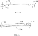
Figure 4 is a cross sectional view through the RF coil. -
Figure 5 is a cross sectional view through the RF coil showing a modified construction. -
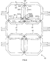
Figure 6 is a plan view of a phased array coil according to the present invention. -
Figure 7 is a cross-sectional view along the lines 7-7 ofFigure 6 . - The following description is taken from the above PCT application and is included for completeness of disclosure herein.
- In
Figure 1 is shown an arrangement for carrying out Magnetic Resonance Imaging and X-Ray imaging of a patient while the patient remains stationary on a patient support table. The arrangement provides aroom 1 in which is mounted a patient support table 10 withdoors 2 at one side of the room for entry into the room of the magnet 3 of an MR imaging system from amagnet bay 1A. The room contains anX-Ray imaging system 4 mounted on rails 5 and includes an X-Ray transmitter 6 andreceiver 7 mounted on a C-shapedsupport 8. The X-Ray system is of a conventional construction commercially available from a manufacturer such as Siemens. The table 10 described and illustrated herein is used in an arrangement where the patient remains in position on the table while imaging is effected using MRI and X-Ray. - The
X-Ray system 4 which co-operates with the moving magnet described above such that the patient can be imaged by either modality on the same table. The patient does not move and at least one of the RF coils remains in place. - The MR is a high-field (e.g. 1.5T or 3T or more) magnet that moves on overhead rails between the two or more rooms as described above. In the system described, one or more of these rooms contains an X-Ray system, either a single-plane or a biplane. When the magnet is moved out of the X-Ray examination room and a set of RF and X-Ray shielded doors is closed, the examination room functions as a conventional X-Ray lab and can be used with conventional equipment. In particular, X-Ray guided interventions may be performed.
- The arrangement may be used in a typical three room configuration with the Angiography Room (AR) on the left, a Diagnostic Room (DR) in the middle, and an Operating Room on the right. The magnet moves on overhead rails between the rooms and can image in each.
- When MR imaging is required, the X-Ray equipment is safely stowed, the doors open, and the magnet is brought into the room over the patient on the table. The RF shield encompasses the AR so all the equipment in the X-Ray examination room is made RF-quiet. MR imaging can then be performed. Afterwards, the magnet is removed from the room, the doors closed, and the X-Ray equipment is returned to its working position.
- The MR scanner is used to provide information complementary to that obtained using X-Ray. It can be used, for example, to perform a baseline assessment prior to intervention as well as to perform a post-intervention assessment. Such an assessment may include perfusion and viability studies of, for example, the heart or of the brain.
- In the arrangement for moving the X-Ray system as shown in
Figure 1 the MR enters the X-Ray examination room and moves over the head end of the table 10. Since the path of the MR passes right through the location of the C-arm stands, the latter must be moved before the magnet may enter. Depending on need, a floor-mounted C-arm stand may be moved on floor rails, floor turntable, or a boom mounted on the floor or wall. Depending on need, a ceiling-mounted C-arm stand may be moved using extended rails to park it at the foot end of the table, by mounting the stand rails on a platform suspended from the movable magnet rails, or by fixing the stand rails on a platform with a telescopic arm to move them laterally. - Using a solution to move a floor-mounted stand together with a mover for a ceiling mounted stand provides a mechanism to move a biplane system. The mover can provide a mounting position of the single plane or biplane at some non-zero angle to the MR rails, e.g., 90 degrees.
- The Patient Handling System or support table is shown in
Figure 2 as indicated generally at 10. The patient support table includes abase 11 of a conventional construction which allows the base to move apatient support portion 12 to required locations in height and in orientation. Suitable drive mechanisms and couplings are known in the art and thus are not required to be described herein. At the top of thebase 11 is mounted the patient support portion in the form of a generallyplanar body 12 formed of a fiber reinforced plastics material so as to define a surface area sufficient for supporting the patient while lying on the patient support portion. - When the imaging is to be of the chest, an
anterior chest coil 31 is arranged to be placed on top of the chest of the patient when in place for imaging on the mattress and also theposterior coil 32 is arranged to be place behind the patient. Similarly when imaging is to be of the head, coils are placed above and below the head of the patient. - In order to avoid moving the patient when changing from the MR imaging system to the X-Ray imaging system, at least the posterior coil remains in place. Thus this coil will be visible in the X-Ray image. The imaging system may be a simple linear X-Ray system or more preferably is a bi-planar rotating system of the type illustrated which takes multiple images around the patient.
- Thus the apparatus for use in imaging of a part of a patient as shown in
Figure 1 includes theradiation imaging system 4 for generating a radiation image of a subject in the field of view using penetrating electromagnetic radiation and the magnetic resonance imaging system for generating an image of the subject including the magnet 3 and the RF coils 31, 32. - A schematic illustration of the
RF coil 32 is shown inFigures 3 and4 and is arranged to remain in place during the radiation imaging using theX-Ray transmitter 50 andreceiver 51 shown only schematically. - The RF coil includes a
support board 33 having side edges 34 and theimaging system 4 defines a field ofview 35 within the area of the board which can be seen in the X-Ray image with portions of the board outside the field of view being outside the image. - The circuitry of the coil includes conductive traces 36,
capacitors 37, afuse 41, adiode 38, a connecting wire 39, and apre-amplifier 40. All of these elements are conventional in general construction and are well known to persons skilled in the art of coil design so that detailed explanation is not required here. - The conductive traces of the RF coil are arranged of a conductive material and typically copper which has a thickness T3 of at least 0.0018 cm (0.0007 inch) and preferably in the range 0.0036 cm to 0.0107 cm (0.0014 inch to 0.0042 inch) which is effective to receive the RF signals from the MR imaging system. Such traces typically cause an attenuation of the penetrating electromagnetic radiation which is clearly visible in the radiation image as compared with a uniform thickness support board material.
- As shown in
Figure 4 , the support board is formed of a non-conductive material in the field of view which has a thickness T1 at locations on the board spaced from the traces selected such that an attenuation of the penetrating electromagnetic radiation at those locations is substantially equal to the attenuation at the conductive traces. Thus the attenuation of the board material at thickness T1 is arranged so that it is equal to the sum of the attenuation caused by the thickness T3 of the trace and thickness T2 of the board at the trace. In this way the attenuation of the penetrating electromagnetic radiation of substantially the whole of the RF coil located within the field of view is substantially constant throughout the field of view. - While the traces are shown in
Figure 4 recessed into shallow areas of the board, the traces can be applied on top of the flat board and the variable thickness of the board applied at the rear. In addition, the board may be flat by filling recesses with a material which is transparent to X-Ray and thus does not affect the attenuation. - In
Figure 5 is shown an alternative arrangement in which the board is formed of abase material 33A and anadditional material 33B is added to the support board at areas separate from the traces, which material is non-conductive and has an attenuation factor that is it is not transparent to X-Ray and is different from thebase material 33A. The base material and the additional material are laminated to form a common structure and the recesses may be filled by additional transparent material. - The conductive traces are arranged to be continuous throughout the field of view so as to have a constant attenuation. That is the conductive traces include no joints and therefore no solder within the field of view. Instead the traces are printed or otherwise applied as a constant continuous strip. Alternatively the traces are formed by etching away unwanted material from a continuous layer on the board leaving traces which are continuous and without joints.
- As shown in
Figure 3 all connector wires 39 from the coil are located outside the field ofview 35 there are no connector wires from the conductive traces within the field of view. - The
capacitors 37 and thefuse 41 for the coil are in most cases necessarily located within the field ofview 35 and these are therefore arranged so that the attenuation of the penetrating electromagnetic radiation is substantially equal to the attenuation of the board at the conductive traces. Thus the capacitor and the fuse is itself formed from conductive traces which are designed and laid out on the board with the required amount of conductive material and the dielectric material to provide the required characteristics and values. The design of such components from conductive traces is known and within the skill of a person skilled in this art. - The support board includes mechanical mounting and
support structures 42 for connection of the board to necessary elements but these are designed and arranged so that they are outside the field of view so that the board is generally constant and continuous and there are no mechanical structures within the field of view. - The
necessary diode 38 is designed and arranged on the traces so that it is located outside field of view. - As an alternative, the diode or other necessary element is located within the field of view where the element has an attenuation different from the conductive traces and of a construction and high attenuation factor such that it cannot reasonably be compensated for by building the remainder of the board up to this high attenuation factor. In this arrangement, where element is located in the field of view, the location of the element in the field of view is constant and the image of the element in the radiation image is removed by software image analysis at the
X-Ray receiver system 51. - Turning now to
Figure 6 and7 there is shown a modification according to the present invention, where the remaining parts of the coil not mentioned are as disclosed above. - The RF phased array coil shown in
Figure 6 includes asupport 60 defined by a single substrate sheet or as shown inFigure 7 two substrate sheets S1 and S2. - On the
substrate 60 is mounted a plurality ofindividual coil loops 61 to 65 formed by conductive traces carried on the substrate. - The
individual coil loops leg 62A ofloop 62 lies adjacent to aleg 61A ofloop 61 with twosections leg 62A ofloop 62 crossing two correspondingsections leg 61A ofcoil loop 61. - At each crossing such as
crossings - A review of the pattern shown in
Figure 6 will show thatloop 63 overlaps insymmetrical manner loops leg 62D. Each leg has crossing points at its ends. The legs 63D1 and 63D2cross leg 62A at crossing 63D4 andleg 61A at crossing 63D5 forming a short section 63D3 between the crossings. The crossing section 63D4 crosses a corresponding section 62A4 of theleg 61. Also a symmetrical arrangement is made betweencoils - This general lay out of loops for phased array coils is previously known but the present invention provides a manner in which the individual loops can be decoupled using the known overlapping layout and also can be invisible in an X-ray image.
- As shown in
Figure 7 , of the crossing sections 63D4 and 63D5 and each of the corresponding sections 62A4 and 61A4 has a thickness T2 in a direction at right angles to the substrate S1, S2 which is less than the thickness T1 of the legs 63D1, 63D2, 63D3, 62A and 61A. - Typically each of the crossing sections and each of the corresponding sections has the thickness T2 equal to one half of thickness T1 and each of the
individual coil loops - As shown in
Figure 6 ,individual coil loop 62 is arranged or printed on the first or top (in the orientation shown) surface S1T of the substrate sheet S1 and theindividual coil loop 63 is arranged on a second opposed surface S1 B of the substrate sheet S1. In an arrangement whereinonly loops loop 61, the substrate is formed by only the single sheet S1. However in the arrangement shown with theloop 61 included and overlapping with both, the second sheet S2 is provided on the bottom of theloop 63 so that its top surface S2T engages theloop 63 with theloop 62 on the bottom surface S2B of the sheet S2. - Thus the conductive traces 61, 62 and 63 of the RF coil arranged of a conductive material have a thickness such that the traces cause an attenuation of the penetrating electromagnetic radiation which is visible in the radiation image and, as explained above in relation to the cited prior application, the support substrate includes non-conductive material in the field of view which has a thickness selected such that an attenuation of the penetrating electromagnetic radiation at locations on the substrate sheet spaced from the traces is substantially equal to the attenuation at locations on the substrate sheet at the conductive traces. It will be noted that the overlapping sections are arranged with the thickness T2 over a length which matches almost so that the summation of the thickness of the loops measured over the whole coil surface is T!. Thus this can be matched with a thickness of the substrate or a material applied to eh substrate to provide a constant aluminum equivalent value over the whole coil structure within the intended field of view of the X-ray system.
- As explained previously, the support substrate sheet can be formed of a single material of different thicknesses. Alternatively the support can be formed from a base material and an additional material different from the base material is added to the support substrate sheet so that the attenuation of the penetrating electromagnetic radiation of substantially the whole of the RF coil located within the field of view is substantially constant throughout the field of view.
- The support formed by substrate sheets S1 and S2 is preferably flexible but this is not essential.
- The conductive traces can be formed of copper or aluminum or other suitable materials well known to a person skilled in this art.
- The support substrate sheets S1 and S2 are formed of fiber reinforced resin such as FR-4.
Claims (10)
- An RF phased array coil (32) for use in an MR imaging system for generating an MR image of a subject and for use in a radiation imaging system for generating a radiation image of said subject using penetrating electromagnetic radiation, the phased array coil comprising:conductive traces;a support (60) defined by at least one substrate sheet (S1);and a plurality of coil loops (61, 62) formed by said conductive traces mounted on said support (60);one of said coil loops (61, 62) overlapping another one of the coil loops (61, 62) so that a leg (61A) of said one coil loop lies adjacent to a leg (62A) of said other coil loop with two sections (61 B, 61 C) at opposite ends of the leg of said one coil loop crossing two corresponding sections (62B, 62C) at opposite ends of the leg of said other coil loop;characterized in that(i) each of the crossing sections (61 B, 61 C) and each of the corresponding sections (62B, 62C) has a thickness (T2) in a direction at right angle to the support (60) which is less than that (T1) of the legs; and(ii) the support (60) is formed of non-conductive material which has a thickness selected such that an attenuation of the penetrating electromagnetic radiation at locations on the support (60) spaced from the traces is substantially equal to the attenuation at locations on the support at the conductive traces;such that an attenuation of the penetrating electromagnetic radiation caused by the RF coil within said radiation image is substantially constant throughout a field of view (35) of the radiation imaging system, when the RF phase array coil is kept in place during radiation imaging within said field of view, to avoid a visible artefact within said radiation image caused by the presence of the RF phased array coil (32).
- The apparatus according to Claim 1 wherein each of the crossing sections (61 B, 61 C) and each of the corresponding sections (62B, 62C) has a thickness (T2) in a direction at right angle to the support which is equal to one half of that (T1) of the legs.
- The apparatus according to claim 1 or 2 wherein each of the coil loops (61, 62) has a thickness (T1) along the full length thereof, with the exception of crossing sections and corresponding sections, which is constant.
- The apparatus according to any one of claims 1 to 3 wherein said one of said coil loops (61, 62) is arranged on a first surface of the substrate sheet (S1) and said other of the individual coil loops (61, 62) is arranged on a second opposed surface of the substrate sheet (S1).
- The apparatus according to any one of claims 1 to 4 wherein the support comprises first and second overlying laminated substrate sheets (S1, S2) and wherein said one of said coil loops (61, 62) is arranged on a first surface of the first substrate sheet (S1) and said other of the individual coil loops is arranged on a second opposed surface of the first substrate sheet (S1) so as to be located between the first and second substrate sheets (S1, S2).
- The apparatus according to Claim 5 wherein there is provided a third of the coil loops which is located on a second opposed surface of the second substrate sheet (S2) and wherein the third coil loop is overlapped with said one and said other (62) of the coil loops.
- The apparatus according to Claim 1 wherein the support is formed from common material.
- The apparatus according to Claim 1 wherein the support is formed from a base material (33A) and an additional material (33B) different from the base material and added to the base material (33A).
- The apparatus according to Claim 8 wherein the base material (33A) and the additional material (33B) are laminated to form a common structure.
- The apparatus according to any preceding claim wherein the support is flexible.
Applications Claiming Priority (1)
| Application Number | Priority Date | Filing Date | Title |
|---|---|---|---|
| US201161484058P | 2011-05-09 | 2011-05-09 |
Publications (2)
| Publication Number | Publication Date |
|---|---|
| EP2523011A1 EP2523011A1 (en) | 2012-11-14 |
| EP2523011B1 true EP2523011B1 (en) | 2017-04-19 |
Family
ID=46208297
Family Applications (1)
| Application Number | Title | Priority Date | Filing Date |
|---|---|---|---|
| EP12167077.2A Active EP2523011B1 (en) | 2011-05-09 | 2012-05-08 | Phased array MR RF coil which is not visible in X-ray image |
Country Status (3)
| Country | Link |
|---|---|
| US (1) | US9081067B2 (en) |
| EP (1) | EP2523011B1 (en) |
| JP (1) | JP5815465B2 (en) |
Families Citing this family (20)
| Publication number | Priority date | Publication date | Assignee | Title |
|---|---|---|---|---|
| ES2445882T3 (en) * | 2009-07-03 | 2014-03-05 | Imris Inc. | RF coil for nuclear magnetic resonance that is not visible in an X-ray image |
| US9474465B2 (en) | 2012-06-27 | 2016-10-25 | Ascension Technology Corporation | System and method for magnetic position tracking |
| KR102038631B1 (en) * | 2013-02-27 | 2019-11-26 | 삼성전자주식회사 | Magnetic resonance imaging system |
| US9404983B2 (en) * | 2013-03-12 | 2016-08-02 | Viewray, Incorporated | Radio frequency transmit coil for magnetic resonance imaging system |
| US20150112187A1 (en) | 2013-10-18 | 2015-04-23 | Imris Inc. | MR Imaging with RF Coil Integrated into Patient Engaging Component |
| US9389071B2 (en) * | 2013-10-24 | 2016-07-12 | Bell Helicopter Textron Inc. | Estimating thickness of a material layer on an aircraft |
| US10191128B2 (en) * | 2014-02-12 | 2019-01-29 | Life Services, LLC | Device and method for loops-over-loops MRI coils |
| EP3194997B1 (en) * | 2014-09-01 | 2023-10-11 | Koninklijke Philips N.V. | Magnetic resonance imaging receive coil with reduced radiation attenuation |
| EP3188659B1 (en) * | 2014-09-03 | 2021-10-20 | Koninklijke Philips N.V. | A magnetic resonance transmit and/or receive antenna system and radiotherapy planning computer program product |
| DE102016214061A1 (en) * | 2016-07-29 | 2018-02-01 | Siemens Healthcare Gmbh | Method for determining two-dimensional image data of at least one sectional area of a detection volume in the context of magnetic resonance imaging |
| JP2019524301A (en) | 2016-08-08 | 2019-09-05 | コーニンクレッカ フィリップス エヌ ヴェKoninklijke Philips N.V. | Mock-up antenna and coil system |
| DE102016220268B4 (en) * | 2016-10-17 | 2018-10-18 | Siemens Healthcare Gmbh | Patient couch and patient care unit |
| KR20190127803A (en) | 2017-03-09 | 2019-11-13 | 더 리전츠 오브 더 유니버시티 오브 캘리포니아 | Single Screen Fabrication of Symmetric Multilayer Magnetic Resonance Imaging (MRI) Receive Coils |
| JP7150415B2 (en) | 2017-04-27 | 2022-10-11 | コーニンクレッカ フィリップス エヌ ヴェ | Medical device for magnetic resonance imaging guided radiation therapy |
| US10694976B2 (en) * | 2017-05-04 | 2020-06-30 | Elekta Ltd. | Squeeze protection |
| GB201905844D0 (en) * | 2019-04-26 | 2019-06-12 | Univ Oxford Innovation Ltd | Radiofrequency coil |
| CA3228129A1 (en) | 2021-08-04 | 2023-02-09 | Viewray Technologies, Inc. | Rf coil assemblies |
| US12350523B2 (en) | 2021-10-22 | 2025-07-08 | Viewray Systems, Inc. | MRI guided radiotherapy |
| US12478803B2 (en) | 2021-10-22 | 2025-11-25 | Viewray Systems, Inc. | Systems, methods and computer software for optimized radiation therapy |
| JP2023154967A (en) * | 2022-04-08 | 2023-10-20 | キヤノンメディカルシステムズ株式会社 | Array coil and manufacturing method |
Family Cites Families (26)
| Publication number | Priority date | Publication date | Assignee | Title |
|---|---|---|---|---|
| US5491415A (en) | 1992-03-05 | 1996-02-13 | Picker International, Inc. | Magnetic resonance scanner with improved packaging for circuitry within the magnetic field |
| DE4226814A1 (en) * | 1992-08-13 | 1994-02-17 | Philips Patentverwaltung | Coil arrangement for MR examinations of the breast |
| US5394087A (en) * | 1993-08-11 | 1995-02-28 | Picker International, Inc. | Multiple quadrature surface coil system for simultaneous imaging in magnetic resonance systems |
| US5666055A (en) | 1995-10-02 | 1997-09-09 | Jones; Randall W. | Surface coil system for a single channel NMR receiver |
| DE19854924C2 (en) * | 1998-11-27 | 2000-11-02 | Siemens Ag | Antenna array for magnetic resonance examinations |
| US6591127B1 (en) | 1999-03-15 | 2003-07-08 | General Electric Company | Integrated multi-modality imaging system and method |
| JP4031964B2 (en) * | 2002-09-09 | 2008-01-09 | 株式会社日立メディコ | Receiver coil for magnetic resonance imaging apparatus and apparatus using the same |
| US6900637B1 (en) * | 2004-03-19 | 2005-05-31 | Igc Medical Advances, Inc. | Phased array coil with center shifted sensitivity |
| US7619413B2 (en) * | 2004-05-04 | 2009-11-17 | The General Hospital Corporation | Transmit-receive array for high field MRI |
| US7282915B2 (en) * | 2004-05-14 | 2007-10-16 | General Electric Company | Multi-turn element RF coil array for multiple channel MRI |
| US7394254B2 (en) | 2005-04-27 | 2008-07-01 | The Board Of Trustees Of The Leland Stanford Junior University | Magnetic resonance imaging having radiation compatible radiofrequency coils |
| US7382132B1 (en) * | 2005-04-29 | 2008-06-03 | General Electric Company | 6-channel array coil for magnetic resonance imaging |
| EP1941293A2 (en) * | 2005-10-19 | 2008-07-09 | Koninklijke Philips Electronics N.V. | Compact and flexible radio frequency coil arrays |
| US7570054B1 (en) * | 2006-04-20 | 2009-08-04 | The General Hospital Corporation | Dynamic magnetic resonance inverse imaging using linear constrained minimum variance beamformer |
| US7394251B2 (en) * | 2006-04-20 | 2008-07-01 | General Hospital Corporation | Dynamic magnetic resonance inverse imaging |
| DE102006055136B4 (en) | 2006-11-22 | 2010-05-06 | Siemens Ag | Radio frequency coil arrangement and magnetic resonance apparatus |
| US7683620B2 (en) * | 2007-05-03 | 2010-03-23 | The General Hospital Corporation | Suppression of noise in MR images and MR spectroscopic images using signal space projection filtering |
| US8369929B2 (en) | 2008-06-04 | 2013-02-05 | Imris Inc. | Patient support table for use in magnetic resonace imaging |
| US8190235B2 (en) | 2008-06-04 | 2012-05-29 | Imris Inc. | System for magnetic resonance and X-Ray imaging |
| US7728592B2 (en) * | 2008-09-17 | 2010-06-01 | Time Medical Holdings Company Limited | Integrated superconductor MRI imaging system |
| ES2445882T3 (en) | 2009-07-03 | 2014-03-05 | Imris Inc. | RF coil for nuclear magnetic resonance that is not visible in an X-ray image |
| CN101998590B (en) | 2009-08-25 | 2015-05-20 | 中兴通讯股份有限公司 | User reachable realization method and multimode terminal |
| WO2011035333A1 (en) * | 2009-09-21 | 2011-03-24 | Time Medical Holdings Company Limited | Superconductor rf coil array |
| US8797029B2 (en) * | 2011-04-20 | 2014-08-05 | Imris Inc | Magnetic resonance signal detection using remotely positioned receive coils |
| US8487615B2 (en) * | 2011-04-20 | 2013-07-16 | Imris Inc | Magnetic resonance signal detection using remotely positioned receive coils |
| US8866481B2 (en) * | 2011-11-07 | 2014-10-21 | Imris Inc. | Stacked coil for magnetic resonance imaging |
-
2012
- 2012-04-25 US US13/455,849 patent/US9081067B2/en active Active
- 2012-05-08 EP EP12167077.2A patent/EP2523011B1/en active Active
- 2012-05-08 JP JP2012107098A patent/JP5815465B2/en active Active
Non-Patent Citations (1)
| Title |
|---|
| None * |
Also Published As
| Publication number | Publication date |
|---|---|
| JP5815465B2 (en) | 2015-11-17 |
| US20120286786A1 (en) | 2012-11-15 |
| EP2523011A1 (en) | 2012-11-14 |
| US9081067B2 (en) | 2015-07-14 |
| JP2012236018A (en) | 2012-12-06 |
Similar Documents
| Publication | Publication Date | Title |
|---|---|---|
| US9081067B2 (en) | Phased array MR RF coil which is not visible in X-ray image | |
| EP2448479B1 (en) | Rf coil for mr imaging which is not visible in x-ray image | |
| EP3544500B1 (en) | Radio frequency coil array for a magnetic resonance imaging system | |
| US11307274B2 (en) | Method and systems for a radio frequency coil assembly | |
| US11280858B2 (en) | Systems for a radio frequency coil for MR imaging | |
| JP2019535424A (en) | System and method for automatic detection in magnetic resonance imaging | |
| US7394254B2 (en) | Magnetic resonance imaging having radiation compatible radiofrequency coils | |
| JP6670306B2 (en) | Z-segmented MRI RF coil with gap and RF screen, and method for applying an RF field to an examination space of an MRI system including the MRI RF coil | |
| WO2018098265A1 (en) | Systems for a radio frequency coil for mr imaging | |
| Bulumulla et al. | Inductively coupled wireless RF coil arrays | |
| CN104422912A (en) | Antenna Apparatus for Receiving Magnetic Resonance Signals | |
| US12092710B2 (en) | MRI tracking device design, fabrication, and methods of use for MRI-guided robotic system | |
| US20160018489A1 (en) | Methods and systems relating to high resolution magnetic resonance imaging | |
| Schmidt et al. | A magnetic resonance imaging–conditional external cardiac defibrillator for resuscitation within the magnetic resonance imaging scanner bore | |
| EP2589976A1 (en) | Stacked RF coil for magnetic resonance imaging | |
| Cheung et al. | Omnidirectional monolithic marker for intra-operative MR-based positional sensing in closed MRI | |
| US20120007601A1 (en) | Inductor assembly for a magnetic resonance imaging system | |
| JP5319745B2 (en) | High frequency coil unit and magnetic resonance imaging apparatus including the same | |
| CN116068471A (en) | Radio frequency coil assembly of magnetic resonance system and assembly method thereof | |
| Lee et al. | A 60‐channel high‐density flexible receive array for pediatric abdominal MRI | |
| Raval | Whole body and upper extremity ultra-high field magnetic resonance imaging: Coil development and clinical implementation |
Legal Events
| Date | Code | Title | Description |
|---|---|---|---|
| PUAI | Public reference made under article 153(3) epc to a published international application that has entered the european phase |
Free format text: ORIGINAL CODE: 0009012 |
|
| AK | Designated contracting states |
Kind code of ref document: A1 Designated state(s): AL AT BE BG CH CY CZ DE DK EE ES FI FR GB GR HR HU IE IS IT LI LT LU LV MC MK MT NL NO PL PT RO RS SE SI SK SM TR |
|
| AX | Request for extension of the european patent |
Extension state: BA ME |
|
| 17P | Request for examination filed |
Effective date: 20130514 |
|
| 17Q | First examination report despatched |
Effective date: 20160504 |
|
| GRAP | Despatch of communication of intention to grant a patent |
Free format text: ORIGINAL CODE: EPIDOSNIGR1 |
|
| GRAJ | Information related to disapproval of communication of intention to grant by the applicant or resumption of examination proceedings by the epo deleted |
Free format text: ORIGINAL CODE: EPIDOSDIGR1 |
|
| GRAP | Despatch of communication of intention to grant a patent |
Free format text: ORIGINAL CODE: EPIDOSNIGR1 |
|
| RIC1 | Information provided on ipc code assigned before grant |
Ipc: A61N 5/10 20060101ALN20160928BHEP Ipc: G01R 33/48 20060101ALN20160928BHEP Ipc: A61B 6/00 20060101ALI20160928BHEP Ipc: A61B 5/00 20060101ALN20160928BHEP Ipc: G01R 33/3415 20060101AFI20160928BHEP Ipc: A61B 5/055 20060101ALN20160928BHEP Ipc: A61B 6/04 20060101ALI20160928BHEP Ipc: G01R 33/36 20060101ALN20160928BHEP |
|
| INTG | Intention to grant announced |
Effective date: 20161014 |
|
| RIC1 | Information provided on ipc code assigned before grant |
Ipc: A61B 6/00 20060101ALI20161004BHEP Ipc: A61B 5/00 20060101ALN20161004BHEP Ipc: A61B 6/04 20060101ALI20161004BHEP Ipc: A61B 5/055 20060101ALN20161004BHEP Ipc: G01R 33/3415 20060101AFI20161004BHEP Ipc: G01R 33/36 20060101ALN20161004BHEP Ipc: G01R 33/48 20060101ALN20161004BHEP Ipc: A61N 5/10 20060101ALN20161004BHEP |
|
| GRAJ | Information related to disapproval of communication of intention to grant by the applicant or resumption of examination proceedings by the epo deleted |
Free format text: ORIGINAL CODE: EPIDOSDIGR1 |
|
| INTG | Intention to grant announced |
Effective date: 20161014 |
|
| STAA | Information on the status of an ep patent application or granted ep patent |
Free format text: STATUS: GRANT OF PATENT IS INTENDED |
|
| GRAP | Despatch of communication of intention to grant a patent |
Free format text: ORIGINAL CODE: EPIDOSNIGR1 |
|
| INTG | Intention to grant announced |
Effective date: 20161027 |
|
| INTG | Intention to grant announced |
Effective date: 20161027 |
|
| GRAJ | Information related to disapproval of communication of intention to grant by the applicant or resumption of examination proceedings by the epo deleted |
Free format text: ORIGINAL CODE: EPIDOSDIGR1 |
|
| STAA | Information on the status of an ep patent application or granted ep patent |
Free format text: STATUS: EXAMINATION IS IN PROGRESS |
|
| GRAP | Despatch of communication of intention to grant a patent |
Free format text: ORIGINAL CODE: EPIDOSNIGR1 |
|
| STAA | Information on the status of an ep patent application or granted ep patent |
Free format text: STATUS: GRANT OF PATENT IS INTENDED |
|
| GRAJ | Information related to disapproval of communication of intention to grant by the applicant or resumption of examination proceedings by the epo deleted |
Free format text: ORIGINAL CODE: EPIDOSDIGR1 |
|
| STAA | Information on the status of an ep patent application or granted ep patent |
Free format text: STATUS: EXAMINATION IS IN PROGRESS |
|
| GRAP | Despatch of communication of intention to grant a patent |
Free format text: ORIGINAL CODE: EPIDOSNIGR1 |
|
| INTG | Intention to grant announced |
Effective date: 20161124 |
|
| STAA | Information on the status of an ep patent application or granted ep patent |
Free format text: STATUS: GRANT OF PATENT IS INTENDED |
|
| INTC | Intention to grant announced (deleted) | ||
| INTG | Intention to grant announced |
Effective date: 20161212 |
|
| INTG | Intention to grant announced |
Effective date: 20161222 |
|
| GRAS | Grant fee paid |
Free format text: ORIGINAL CODE: EPIDOSNIGR3 |
|
| GRAA | (expected) grant |
Free format text: ORIGINAL CODE: 0009210 |
|
| STAA | Information on the status of an ep patent application or granted ep patent |
Free format text: STATUS: THE PATENT HAS BEEN GRANTED |
|
| AK | Designated contracting states |
Kind code of ref document: B1 Designated state(s): AL AT BE BG CH CY CZ DE DK EE ES FI FR GB GR HR HU IE IS IT LI LT LU LV MC MK MT NL NO PL PT RO RS SE SI SK SM TR |
|
| REG | Reference to a national code |
Ref country code: GB Ref legal event code: FG4D |
|
| REG | Reference to a national code |
Ref country code: CH Ref legal event code: EP |
|
| REG | Reference to a national code |
Ref country code: AT Ref legal event code: REF Ref document number: 886479 Country of ref document: AT Kind code of ref document: T Effective date: 20170515 |
|
| REG | Reference to a national code |
Ref country code: IE Ref legal event code: FG4D |
|
| REG | Reference to a national code |
Ref country code: DE Ref legal event code: R096 Ref document number: 602012031241 Country of ref document: DE |
|
| REG | Reference to a national code |
Ref country code: FR Ref legal event code: PLFP Year of fee payment: 6 |
|
| REG | Reference to a national code |
Ref country code: NL Ref legal event code: MP Effective date: 20170419 |
|
| REG | Reference to a national code |
Ref country code: LT Ref legal event code: MG4D |
|
| REG | Reference to a national code |
Ref country code: AT Ref legal event code: MK05 Ref document number: 886479 Country of ref document: AT Kind code of ref document: T Effective date: 20170419 |
|
| PG25 | Lapsed in a contracting state [announced via postgrant information from national office to epo] |
Ref country code: NL Free format text: LAPSE BECAUSE OF FAILURE TO SUBMIT A TRANSLATION OF THE DESCRIPTION OR TO PAY THE FEE WITHIN THE PRESCRIBED TIME-LIMIT Effective date: 20170419 |
|
| PG25 | Lapsed in a contracting state [announced via postgrant information from national office to epo] |
Ref country code: FI Free format text: LAPSE BECAUSE OF FAILURE TO SUBMIT A TRANSLATION OF THE DESCRIPTION OR TO PAY THE FEE WITHIN THE PRESCRIBED TIME-LIMIT Effective date: 20170419 Ref country code: GR Free format text: LAPSE BECAUSE OF FAILURE TO SUBMIT A TRANSLATION OF THE DESCRIPTION OR TO PAY THE FEE WITHIN THE PRESCRIBED TIME-LIMIT Effective date: 20170720 Ref country code: HR Free format text: LAPSE BECAUSE OF FAILURE TO SUBMIT A TRANSLATION OF THE DESCRIPTION OR TO PAY THE FEE WITHIN THE PRESCRIBED TIME-LIMIT Effective date: 20170419 Ref country code: NO Free format text: LAPSE BECAUSE OF FAILURE TO SUBMIT A TRANSLATION OF THE DESCRIPTION OR TO PAY THE FEE WITHIN THE PRESCRIBED TIME-LIMIT Effective date: 20170719 Ref country code: ES Free format text: LAPSE BECAUSE OF FAILURE TO SUBMIT A TRANSLATION OF THE DESCRIPTION OR TO PAY THE FEE WITHIN THE PRESCRIBED TIME-LIMIT Effective date: 20170419 Ref country code: AT Free format text: LAPSE BECAUSE OF FAILURE TO SUBMIT A TRANSLATION OF THE DESCRIPTION OR TO PAY THE FEE WITHIN THE PRESCRIBED TIME-LIMIT Effective date: 20170419 Ref country code: LT Free format text: LAPSE BECAUSE OF FAILURE TO SUBMIT A TRANSLATION OF THE DESCRIPTION OR TO PAY THE FEE WITHIN THE PRESCRIBED TIME-LIMIT Effective date: 20170419 |
|
| PG25 | Lapsed in a contracting state [announced via postgrant information from national office to epo] |
Ref country code: PL Free format text: LAPSE BECAUSE OF FAILURE TO SUBMIT A TRANSLATION OF THE DESCRIPTION OR TO PAY THE FEE WITHIN THE PRESCRIBED TIME-LIMIT Effective date: 20170419 Ref country code: BG Free format text: LAPSE BECAUSE OF FAILURE TO SUBMIT A TRANSLATION OF THE DESCRIPTION OR TO PAY THE FEE WITHIN THE PRESCRIBED TIME-LIMIT Effective date: 20170719 Ref country code: SE Free format text: LAPSE BECAUSE OF FAILURE TO SUBMIT A TRANSLATION OF THE DESCRIPTION OR TO PAY THE FEE WITHIN THE PRESCRIBED TIME-LIMIT Effective date: 20170419 Ref country code: RS Free format text: LAPSE BECAUSE OF FAILURE TO SUBMIT A TRANSLATION OF THE DESCRIPTION OR TO PAY THE FEE WITHIN THE PRESCRIBED TIME-LIMIT Effective date: 20170419 Ref country code: LV Free format text: LAPSE BECAUSE OF FAILURE TO SUBMIT A TRANSLATION OF THE DESCRIPTION OR TO PAY THE FEE WITHIN THE PRESCRIBED TIME-LIMIT Effective date: 20170419 Ref country code: IS Free format text: LAPSE BECAUSE OF FAILURE TO SUBMIT A TRANSLATION OF THE DESCRIPTION OR TO PAY THE FEE WITHIN THE PRESCRIBED TIME-LIMIT Effective date: 20170819 |
|
| REG | Reference to a national code |
Ref country code: CH Ref legal event code: PL |
|
| REG | Reference to a national code |
Ref country code: DE Ref legal event code: R097 Ref document number: 602012031241 Country of ref document: DE |
|
| PG25 | Lapsed in a contracting state [announced via postgrant information from national office to epo] |
Ref country code: CZ Free format text: LAPSE BECAUSE OF FAILURE TO SUBMIT A TRANSLATION OF THE DESCRIPTION OR TO PAY THE FEE WITHIN THE PRESCRIBED TIME-LIMIT Effective date: 20170419 Ref country code: DK Free format text: LAPSE BECAUSE OF FAILURE TO SUBMIT A TRANSLATION OF THE DESCRIPTION OR TO PAY THE FEE WITHIN THE PRESCRIBED TIME-LIMIT Effective date: 20170419 Ref country code: SK Free format text: LAPSE BECAUSE OF FAILURE TO SUBMIT A TRANSLATION OF THE DESCRIPTION OR TO PAY THE FEE WITHIN THE PRESCRIBED TIME-LIMIT Effective date: 20170419 Ref country code: RO Free format text: LAPSE BECAUSE OF FAILURE TO SUBMIT A TRANSLATION OF THE DESCRIPTION OR TO PAY THE FEE WITHIN THE PRESCRIBED TIME-LIMIT Effective date: 20170419 Ref country code: MC Free format text: LAPSE BECAUSE OF FAILURE TO SUBMIT A TRANSLATION OF THE DESCRIPTION OR TO PAY THE FEE WITHIN THE PRESCRIBED TIME-LIMIT Effective date: 20170419 Ref country code: EE Free format text: LAPSE BECAUSE OF FAILURE TO SUBMIT A TRANSLATION OF THE DESCRIPTION OR TO PAY THE FEE WITHIN THE PRESCRIBED TIME-LIMIT Effective date: 20170419 |
|
| REG | Reference to a national code |
Ref country code: IE Ref legal event code: MM4A |
|
| PLBE | No opposition filed within time limit |
Free format text: ORIGINAL CODE: 0009261 |
|
| STAA | Information on the status of an ep patent application or granted ep patent |
Free format text: STATUS: NO OPPOSITION FILED WITHIN TIME LIMIT |
|
| PG25 | Lapsed in a contracting state [announced via postgrant information from national office to epo] |
Ref country code: CH Free format text: LAPSE BECAUSE OF NON-PAYMENT OF DUE FEES Effective date: 20170531 Ref country code: LI Free format text: LAPSE BECAUSE OF NON-PAYMENT OF DUE FEES Effective date: 20170531 Ref country code: IT Free format text: LAPSE BECAUSE OF FAILURE TO SUBMIT A TRANSLATION OF THE DESCRIPTION OR TO PAY THE FEE WITHIN THE PRESCRIBED TIME-LIMIT Effective date: 20170419 Ref country code: SM Free format text: LAPSE BECAUSE OF FAILURE TO SUBMIT A TRANSLATION OF THE DESCRIPTION OR TO PAY THE FEE WITHIN THE PRESCRIBED TIME-LIMIT Effective date: 20170419 |
|
| 26N | No opposition filed |
Effective date: 20180122 |
|
| GBPC | Gb: european patent ceased through non-payment of renewal fee |
Effective date: 20170719 |
|
| PG25 | Lapsed in a contracting state [announced via postgrant information from national office to epo] |
Ref country code: LU Free format text: LAPSE BECAUSE OF NON-PAYMENT OF DUE FEES Effective date: 20170508 |
|
| REG | Reference to a national code |
Ref country code: BE Ref legal event code: MM Effective date: 20170531 |
|
| PG25 | Lapsed in a contracting state [announced via postgrant information from national office to epo] |
Ref country code: GB Free format text: LAPSE BECAUSE OF NON-PAYMENT OF DUE FEES Effective date: 20170719 Ref country code: IE Free format text: LAPSE BECAUSE OF NON-PAYMENT OF DUE FEES Effective date: 20170508 |
|
| REG | Reference to a national code |
Ref country code: FR Ref legal event code: PLFP Year of fee payment: 7 |
|
| PG25 | Lapsed in a contracting state [announced via postgrant information from national office to epo] |
Ref country code: SI Free format text: LAPSE BECAUSE OF FAILURE TO SUBMIT A TRANSLATION OF THE DESCRIPTION OR TO PAY THE FEE WITHIN THE PRESCRIBED TIME-LIMIT Effective date: 20170419 |
|
| PG25 | Lapsed in a contracting state [announced via postgrant information from national office to epo] |
Ref country code: BE Free format text: LAPSE BECAUSE OF NON-PAYMENT OF DUE FEES Effective date: 20170531 |
|
| PG25 | Lapsed in a contracting state [announced via postgrant information from national office to epo] |
Ref country code: MT Free format text: LAPSE BECAUSE OF NON-PAYMENT OF DUE FEES Effective date: 20170508 |
|
| PG25 | Lapsed in a contracting state [announced via postgrant information from national office to epo] |
Ref country code: HU Free format text: LAPSE BECAUSE OF FAILURE TO SUBMIT A TRANSLATION OF THE DESCRIPTION OR TO PAY THE FEE WITHIN THE PRESCRIBED TIME-LIMIT; INVALID AB INITIO Effective date: 20120508 |
|
| PG25 | Lapsed in a contracting state [announced via postgrant information from national office to epo] |
Ref country code: CY Free format text: LAPSE BECAUSE OF NON-PAYMENT OF DUE FEES Effective date: 20170419 |
|
| PG25 | Lapsed in a contracting state [announced via postgrant information from national office to epo] |
Ref country code: MK Free format text: LAPSE BECAUSE OF FAILURE TO SUBMIT A TRANSLATION OF THE DESCRIPTION OR TO PAY THE FEE WITHIN THE PRESCRIBED TIME-LIMIT Effective date: 20170419 |
|
| PG25 | Lapsed in a contracting state [announced via postgrant information from national office to epo] |
Ref country code: TR Free format text: LAPSE BECAUSE OF FAILURE TO SUBMIT A TRANSLATION OF THE DESCRIPTION OR TO PAY THE FEE WITHIN THE PRESCRIBED TIME-LIMIT Effective date: 20170419 |
|
| PG25 | Lapsed in a contracting state [announced via postgrant information from national office to epo] |
Ref country code: PT Free format text: LAPSE BECAUSE OF FAILURE TO SUBMIT A TRANSLATION OF THE DESCRIPTION OR TO PAY THE FEE WITHIN THE PRESCRIBED TIME-LIMIT Effective date: 20170419 |
|
| PG25 | Lapsed in a contracting state [announced via postgrant information from national office to epo] |
Ref country code: AL Free format text: LAPSE BECAUSE OF FAILURE TO SUBMIT A TRANSLATION OF THE DESCRIPTION OR TO PAY THE FEE WITHIN THE PRESCRIBED TIME-LIMIT Effective date: 20170419 |
|
| PGFP | Annual fee paid to national office [announced via postgrant information from national office to epo] |
Ref country code: DE Payment date: 20250521 Year of fee payment: 14 |
|
| PGFP | Annual fee paid to national office [announced via postgrant information from national office to epo] |
Ref country code: FR Payment date: 20250528 Year of fee payment: 14 |