EP3194997B1 - Magnetic resonance imaging receive coil with reduced radiation attenuation - Google Patents
Magnetic resonance imaging receive coil with reduced radiation attenuation Download PDFInfo
- Publication number
- EP3194997B1 EP3194997B1 EP15750366.5A EP15750366A EP3194997B1 EP 3194997 B1 EP3194997 B1 EP 3194997B1 EP 15750366 A EP15750366 A EP 15750366A EP 3194997 B1 EP3194997 B1 EP 3194997B1
- Authority
- EP
- European Patent Office
- Prior art keywords
- magnetic resonance
- zone
- antenna
- coil
- medical instrument
- Prior art date
- Legal status (The legal status is an assumption and is not a legal conclusion. Google has not performed a legal analysis and makes no representation as to the accuracy of the status listed.)
- Active
Links
- 230000005855 radiation Effects 0.000 title claims description 95
- 238000002595 magnetic resonance imaging Methods 0.000 title claims description 26
- 239000006260 foam Substances 0.000 claims description 28
- 239000004020 conductor Substances 0.000 claims description 19
- 238000003384 imaging method Methods 0.000 claims description 18
- 239000011148 porous material Substances 0.000 claims description 16
- 239000004642 Polyimide Substances 0.000 claims description 10
- 229920001721 polyimide Polymers 0.000 claims description 10
- 239000004696 Poly ether ether ketone Substances 0.000 claims description 7
- 229920002530 polyetherether ketone Polymers 0.000 claims description 7
- DQXBYHZEEUGOBF-UHFFFAOYSA-N but-3-enoic acid;ethene Chemical compound C=C.OC(=O)CC=C DQXBYHZEEUGOBF-UHFFFAOYSA-N 0.000 claims description 6
- 239000005038 ethylene vinyl acetate Substances 0.000 claims description 6
- 229920001200 poly(ethylene-vinyl acetate) Polymers 0.000 claims description 6
- 230000001678 irradiating effect Effects 0.000 claims description 4
- 239000004743 Polypropylene Substances 0.000 claims description 3
- -1 polypropylene Polymers 0.000 claims description 3
- 229920001155 polypropylene Polymers 0.000 claims description 3
- 239000004814 polyurethane Substances 0.000 claims description 3
- JUPQTSLXMOCDHR-UHFFFAOYSA-N benzene-1,4-diol;bis(4-fluorophenyl)methanone Chemical compound OC1=CC=C(O)C=C1.C1=CC(F)=CC=C1C(=O)C1=CC=C(F)C=C1 JUPQTSLXMOCDHR-UHFFFAOYSA-N 0.000 claims 3
- 229920002635 polyurethane Polymers 0.000 claims 2
- 239000004952 Polyamide Substances 0.000 claims 1
- 229920002647 polyamide Polymers 0.000 claims 1
- 239000010410 layer Substances 0.000 description 37
- 238000003860 storage Methods 0.000 description 28
- 239000000463 material Substances 0.000 description 25
- RYGMFSIKBFXOCR-UHFFFAOYSA-N Copper Chemical compound [Cu] RYGMFSIKBFXOCR-UHFFFAOYSA-N 0.000 description 22
- 229910052802 copper Inorganic materials 0.000 description 22
- 239000010949 copper Substances 0.000 description 22
- 238000001959 radiotherapy Methods 0.000 description 12
- 230000006870 function Effects 0.000 description 10
- 238000004590 computer program Methods 0.000 description 8
- 238000010586 diagram Methods 0.000 description 7
- 238000012545 processing Methods 0.000 description 7
- 238000010521 absorption reaction Methods 0.000 description 6
- 238000013461 design Methods 0.000 description 6
- 238000000034 method Methods 0.000 description 6
- 238000002600 positron emission tomography Methods 0.000 description 6
- 230000009286 beneficial effect Effects 0.000 description 5
- 230000003287 optical effect Effects 0.000 description 4
- 239000004800 polyvinyl chloride Substances 0.000 description 4
- XAGFODPZIPBFFR-UHFFFAOYSA-N aluminium Chemical compound [Al] XAGFODPZIPBFFR-UHFFFAOYSA-N 0.000 description 3
- 229910052782 aluminium Inorganic materials 0.000 description 3
- 230000007274 generation of a signal involved in cell-cell signaling Effects 0.000 description 3
- 238000012986 modification Methods 0.000 description 3
- 230000004048 modification Effects 0.000 description 3
- 238000001208 nuclear magnetic resonance pulse sequence Methods 0.000 description 3
- 229920000915 polyvinyl chloride Polymers 0.000 description 3
- 239000007787 solid Substances 0.000 description 3
- 239000000758 substrate Substances 0.000 description 3
- 239000012790 adhesive layer Substances 0.000 description 2
- 210000003484 anatomy Anatomy 0.000 description 2
- 230000008901 benefit Effects 0.000 description 2
- 210000004556 brain Anatomy 0.000 description 2
- 230000001419 dependent effect Effects 0.000 description 2
- 238000009826 distribution Methods 0.000 description 2
- 230000000694 effects Effects 0.000 description 2
- 238000003475 lamination Methods 0.000 description 2
- 230000003902 lesion Effects 0.000 description 2
- 239000007788 liquid Substances 0.000 description 2
- 238000004519 manufacturing process Methods 0.000 description 2
- 238000005259 measurement Methods 0.000 description 2
- 210000000056 organ Anatomy 0.000 description 2
- 230000008569 process Effects 0.000 description 2
- 230000000644 propagated effect Effects 0.000 description 2
- 230000035945 sensitivity Effects 0.000 description 2
- 239000011343 solid material Substances 0.000 description 2
- 238000012800 visualization Methods 0.000 description 2
- 229920005830 Polyurethane Foam Polymers 0.000 description 1
- BQCADISMDOOEFD-UHFFFAOYSA-N Silver Chemical compound [Ag] BQCADISMDOOEFD-UHFFFAOYSA-N 0.000 description 1
- 241000405217 Viola <butterfly> Species 0.000 description 1
- 230000003187 abdominal effect Effects 0.000 description 1
- 239000000853 adhesive Substances 0.000 description 1
- 230000001070 adhesive effect Effects 0.000 description 1
- 230000002238 attenuated effect Effects 0.000 description 1
- 230000004888 barrier function Effects 0.000 description 1
- 230000005540 biological transmission Effects 0.000 description 1
- 230000000903 blocking effect Effects 0.000 description 1
- 230000015556 catabolic process Effects 0.000 description 1
- 235000019993 champagne Nutrition 0.000 description 1
- 238000004891 communication Methods 0.000 description 1
- 239000002131 composite material Substances 0.000 description 1
- 238000010276 construction Methods 0.000 description 1
- 230000003247 decreasing effect Effects 0.000 description 1
- 238000006731 degradation reaction Methods 0.000 description 1
- 238000001514 detection method Methods 0.000 description 1
- 239000006261 foam material Substances 0.000 description 1
- 239000003292 glue Substances 0.000 description 1
- 230000010354 integration Effects 0.000 description 1
- 238000013152 interventional procedure Methods 0.000 description 1
- 239000004973 liquid crystal related substance Substances 0.000 description 1
- 239000004620 low density foam Substances 0.000 description 1
- 239000000203 mixture Substances 0.000 description 1
- 239000012811 non-conductive material Substances 0.000 description 1
- 239000013307 optical fiber Substances 0.000 description 1
- 239000000123 paper Substances 0.000 description 1
- 229920003023 plastic Polymers 0.000 description 1
- 239000004033 plastic Substances 0.000 description 1
- 239000004417 polycarbonate Substances 0.000 description 1
- 229920000515 polycarbonate Polymers 0.000 description 1
- 239000011496 polyurethane foam Substances 0.000 description 1
- 229910052709 silver Inorganic materials 0.000 description 1
- 239000004332 silver Substances 0.000 description 1
- 230000008685 targeting Effects 0.000 description 1
- 210000003813 thumb Anatomy 0.000 description 1
- 238000003325 tomography Methods 0.000 description 1
- 230000000007 visual effect Effects 0.000 description 1
- 238000004804 winding Methods 0.000 description 1
Images


Classifications
-
- A—HUMAN NECESSITIES
- A61—MEDICAL OR VETERINARY SCIENCE; HYGIENE
- A61N—ELECTROTHERAPY; MAGNETOTHERAPY; RADIATION THERAPY; ULTRASOUND THERAPY
- A61N5/00—Radiation therapy
- A61N5/10—X-ray therapy; Gamma-ray therapy; Particle-irradiation therapy
- A61N5/1048—Monitoring, verifying, controlling systems and methods
- A61N5/1049—Monitoring, verifying, controlling systems and methods for verifying the position of the patient with respect to the radiation beam
-
- G—PHYSICS
- G01—MEASURING; TESTING
- G01R—MEASURING ELECTRIC VARIABLES; MEASURING MAGNETIC VARIABLES
- G01R33/00—Arrangements or instruments for measuring magnetic variables
- G01R33/20—Arrangements or instruments for measuring magnetic variables involving magnetic resonance
- G01R33/28—Details of apparatus provided for in groups G01R33/44 - G01R33/64
- G01R33/32—Excitation or detection systems, e.g. using radio frequency signals
- G01R33/34—Constructional details, e.g. resonators, specially adapted to MR
- G01R33/341—Constructional details, e.g. resonators, specially adapted to MR comprising surface coils
-
- G—PHYSICS
- G01—MEASURING; TESTING
- G01R—MEASURING ELECTRIC VARIABLES; MEASURING MAGNETIC VARIABLES
- G01R33/00—Arrangements or instruments for measuring magnetic variables
- G01R33/20—Arrangements or instruments for measuring magnetic variables involving magnetic resonance
- G01R33/44—Arrangements or instruments for measuring magnetic variables involving magnetic resonance using nuclear magnetic resonance [NMR]
- G01R33/48—NMR imaging systems
- G01R33/4808—Multimodal MR, e.g. MR combined with positron emission tomography [PET], MR combined with ultrasound or MR combined with computed tomography [CT]
- G01R33/4812—MR combined with X-ray or computed tomography [CT]
-
- A—HUMAN NECESSITIES
- A61—MEDICAL OR VETERINARY SCIENCE; HYGIENE
- A61B—DIAGNOSIS; SURGERY; IDENTIFICATION
- A61B2562/00—Details of sensors; Constructional details of sensor housings or probes; Accessories for sensors
- A61B2562/16—Details of sensor housings or probes; Details of structural supports for sensors
- A61B2562/17—Comprising radiolucent components
-
- A—HUMAN NECESSITIES
- A61—MEDICAL OR VETERINARY SCIENCE; HYGIENE
- A61B—DIAGNOSIS; SURGERY; IDENTIFICATION
- A61B5/00—Measuring for diagnostic purposes; Identification of persons
- A61B5/05—Detecting, measuring or recording for diagnosis by means of electric currents or magnetic fields; Measuring using microwaves or radio waves
- A61B5/055—Detecting, measuring or recording for diagnosis by means of electric currents or magnetic fields; Measuring using microwaves or radio waves involving electronic [EMR] or nuclear [NMR] magnetic resonance, e.g. magnetic resonance imaging
-
- A—HUMAN NECESSITIES
- A61—MEDICAL OR VETERINARY SCIENCE; HYGIENE
- A61N—ELECTROTHERAPY; MAGNETOTHERAPY; RADIATION THERAPY; ULTRASOUND THERAPY
- A61N5/00—Radiation therapy
- A61N5/10—X-ray therapy; Gamma-ray therapy; Particle-irradiation therapy
- A61N5/1048—Monitoring, verifying, controlling systems and methods
- A61N5/1049—Monitoring, verifying, controlling systems and methods for verifying the position of the patient with respect to the radiation beam
- A61N2005/1055—Monitoring, verifying, controlling systems and methods for verifying the position of the patient with respect to the radiation beam using magnetic resonance imaging [MRI]
-
- G—PHYSICS
- G01—MEASURING; TESTING
- G01R—MEASURING ELECTRIC VARIABLES; MEASURING MAGNETIC VARIABLES
- G01R33/00—Arrangements or instruments for measuring magnetic variables
- G01R33/20—Arrangements or instruments for measuring magnetic variables involving magnetic resonance
- G01R33/28—Details of apparatus provided for in groups G01R33/44 - G01R33/64
- G01R33/32—Excitation or detection systems, e.g. using radio frequency signals
- G01R33/34—Constructional details, e.g. resonators, specially adapted to MR
- G01R33/34007—Manufacture of RF coils, e.g. using printed circuit board technology; additional hardware for providing mechanical support to the RF coil assembly or to part thereof, e.g. a support for moving the coil assembly relative to the remainder of the MR system
-
- G—PHYSICS
- G01—MEASURING; TESTING
- G01R—MEASURING ELECTRIC VARIABLES; MEASURING MAGNETIC VARIABLES
- G01R33/00—Arrangements or instruments for measuring magnetic variables
- G01R33/20—Arrangements or instruments for measuring magnetic variables involving magnetic resonance
- G01R33/28—Details of apparatus provided for in groups G01R33/44 - G01R33/64
- G01R33/32—Excitation or detection systems, e.g. using radio frequency signals
- G01R33/34—Constructional details, e.g. resonators, specially adapted to MR
- G01R33/341—Constructional details, e.g. resonators, specially adapted to MR comprising surface coils
- G01R33/3415—Constructional details, e.g. resonators, specially adapted to MR comprising surface coils comprising arrays of sub-coils, i.e. phased-array coils with flexible receiver channels
Definitions
- a computer readable signal medium may include a propagated data signal with computer executable code embodied therein, for example, in baseband or as part of a carrier wave. Such a propagated signal may take any of a variety of forms, including, but not limited to, electro-magnetic, optical, or any suitable combination thereof.
- a computer readable signal medium may be any computer readable medium that is not a computer readable storage medium and that can communicate, propagate, or transport a program for use by or in connection with an instruction execution system, apparatus, or device.
- Computer executable code may comprise machine executable instructions or a program which causes a processor to perform an aspect of the present invention.
- Computer executable code for carrying out operations for aspects of the present invention may be written in any combination of one or more programming languages, including an object oriented programming language such as Java, Smalltalk, C++ or the like and conventional procedural programming languages, such as the "C" programming language or similar programming languages and compiled into machine executable instructions.
- object oriented programming language such as Java, Smalltalk, C++ or the like
- conventional procedural programming languages such as the "C" programming language or similar programming languages and compiled into machine executable instructions.
- the computer executable code may be in the form of a higher level language or in a pre-compiled form and be used in conjunction with an interpreter which generates the machine executable instructions on the fly.
- the coil former is divided into an irradiation zone and at least one reduced radiation zone.
- the pre-amplifier for each of the one or multiple antenna elements is located within the at least one reduced radiation zone.
- the one or multiple antenna elements are located at least partially within the irradiation zone.
- the coil former has a perimeter that forms edges.
- the magnetic resonance antenna is a surface coil. So although the surface coil may not be flat it predominantly has a surface which is bounded by edges. The edges extend about the perimeter of the surface coil.
- the irradiation zone extends continuously from a first edge of the perimeter to a second edge of the perimeter. The first edge and the second edge are opposing or opposite edges.
- the porous material is any one of the following: A foam, expanded polypropylene, Polyutethane foam, Polyimide foam, Polyether ether ketone (PEEK) foam, a corrugated structure, corrugated cardboard, a honeycomb structure, and/or has an attenuation of less than 2% for X-ray radiation between 1.8 mega electron volts and 8 MeV. In another embodiment the porous material has an attenuation of less than 1% for X-ray radiation between 1.8 MeV and 8 MeV.
- the rigid coil former is formed from a solid plastic between 0.2 and 0.8 millimeters thick.
- the biocompatible layer is any one of the following: Ethylene-vinyl acetate, PVC foam, polyurethane (PU) foam, PEEK foam, and Polyvinyl chloride (PVC) foam.
- the medical instrument comprises a LINAC with a X-ray source configured for directing X-ray radiation at a target zone.
- the LINAC is adapted for rotating the X-ray source about a rotational axis.
- the medical instrument further comprises a magnetic resonance imaging system configured for acquiring magnetic resonance data with the magnetic resonance antenna from an imaging zone.
- the target zone is within the imaging zone.
- the X-ray source is adapted for rotating at least partially about the magnet.
- the irradiation zone within a receive coil can have one or more of the following elements:
- the core of the structure is made of rigid, low density foam or material e.g. EPP (Expanded polypropylene).
- EPP Exanded polypropylene
- the material can be either machined or molded to its form. This part forms the basis for the structure in terms of rigidity.
- the density of the material is low, ⁇ 100 kg/m3.
- the outer surface of the structure is made of low density soft foam or material e.g. EVA (Ethylene-vinyl acetate).
- EVA Ethylene-vinyl acetate
- This foam or material is providing the biocompatible surface for the structure. Due to its closed cell structure, it also prevents liquids to ingress the structure.
- the material density is ⁇ 50 kg/ m3.
- Figs. 8, 9 and 10 show several different examples.
- the examples shown in Figs. 8, 9 and 10 show straight cross-sections.
- these straight cross-sections are only exemplary and the coils or antennas may be curved as is illustrated in Figs. 3 , 5, 6 and 7 .
- a split cylindrical magnet is similar to a standard cylindrical magnet, except that the cryostat has been split into two sections to allow access to the iso-plane of the magnet, such magnets may for instance be used to provide a space for X-ray radiation to reach a subject 1536.
- An open magnet has two magnet sections, one above the other with a space in-between that is large enough to receive a subject: the arrangement of the two sections is similar to that of a Helmholtz coil. Open magnets are popular, because the subject is less confined. Inside the cryostat of the cylindrical magnet there is a collection of superconducting coils.
- the magnet 1512 shown in this example is a modifed cylindrical superconducting magnet.
- the magnet 1512 has a cryostat 1514 with superconducting coils within it 1516.
- the magnet is designed such that a X-ray radiation beam 1542 does not intersect the superconducting coils 1516.
- the materials and thicknesses along the beam path 1542 maybe chosen to reduce the attenuation of the X-ray radiation.
- a split or open magnet design may be used instead to eliminate the absorption of radiation by the magnet 1512.
- a subject support 1534 for supporting a subject 1536.
- the subject support 1534 may be positioned by a mechanical positioning system 1537.
- Within the subject 1536 there is a target zone 1538.
- the axis of gantry rotation 1540 is coaxial in this particular example with the cylindrical axis of the magnet 1512.
- the subject support 1534 has been positioned such that the target zone 1538 lies on the axis 1540 of gantry rotation.
- the X-ray source 1508 is shown as generating a radiation beam 1542 which passes through the collimator 1510 and through the target zone 1538. As the radiation source 1508 is rotated about the axis 1540 the target zone 1538 will always be targeted by the radiation beam 1542.
- the computer storage 1552 is shown as containing a treatment plan 1560.
- the computer storage 1552 is further shown as containing a pulse sequence 1562.
- a pulse sequence as used herein is a set of commands used to control various components of the magnetic resonance imaging system 1504 to acquire magnetic resonance data 1564.
- the computer storage 1552 is shown as containing magnetic resonance data 1564 that was acquired using the magnetic resonance imaging system 1504.
Description
- The invention relates to radiotherapy, in particular to radiotherapy combined with magnetic resonance imaging.
- In routine practice of Radiotherapy (RT), the subject is positioned relative to the stationary center of the rotating arc carrying the RT source. Positioning implies both height and lateral adjustment of the subject table. This positioning is required to optimize the dose in the lesion beyond variation that can be obtained by applying RT rays from different angles.
- Integration of MR and Linear Accelerators (LINAC) opens new horizons in Radiotherapy by improved lesion targeting, especially for moving organs. In a practical implementation proposal, the LINAC rotates around the subject to hit the gross target volume (GTV) and clinical target volume (CTV) from multiple angles while minimizing the radiation exposure for surrounding tissues.
- The combination of magnetic resonance apparatuses and LINAC radiotherapy sources is known. Typically a LINAC source is placed on a rotating gantry about the magnet and designing the magnet such that the LINAC rotates in a zero-field region of the magnet. Another particular feature of the concept is the use of a split gradient coil which prevents attenuation of the LINAC beam.
- In Champagne et. al. "A Novel Radiolucent Phased Array Design Suitable ofr MR Guided Radiation Therapy," Proc. Intl. Soc. Mag. Reson. Med 19 (2011) an X-ray transparent phased array coil for magnetic resonance imaging is described. The coil was constructed so that a combination of thicknesses of copper and the solid FR4 substrate such that it will be transparent during x-ray imaging and radiation therapy.
- United States patent application publicaiton
US 2010/066373 A1 discloses A local coil facility is disclosed for a magnetic resonance tomography apparatus for examining an examination object. The local coil facility includes at least one electronic processing system, a high frequency antenna, and an antenna housing to cover the highfrequency antenna and the at least one electronic processing system, the antenna housing having at least one wall close to the object and at least one wall away from the object. To reduce or even minimize the attenuation of PET radiation in a combined MR/PET device and thus in particular to ensure a better signal to noise ratio for the PET measurement, it is proposed that the surfaces of the wall away from the object are essentially tangential to the examination object. - The journal publication VIOLA RIEKE ET AL: "X-ray compatible radiofrequency coll for magnetic resonance imaging", MAGNETIC RESONANCE IN MEDICINE, JOHN WILEY & SONS, INC, US, vol. 53, no. 6, 1 June 2005 (2005-06-01), pages 1409-1414 discloses that the range of RF coils that can be used in combined X-ray/MR (XMR) systems is limited because many conventional coils contain highly X-ray attenuating materials that are visible in the X-ray images and potentially obscure patient anatomy. It further discloses, an X-ray compatible coil design that has minimal X-ray attenuation in the field of view (FOV) of the X-ray image is presented. In this design, aluminum is used for the loop conductor and discrete elements of the coil are eliminated from the X-ray FOV. A surface coil and an abdominal phased array coil were built using the X-ray compatible design. X-ray attenuation and MR imaging properties of the coils were evaluated and compared to conventional coils. The X-ray compatible phased array coil was used to image patients during two interventional procedures in the XMR system. The X-ray compatible coils allowed for fluoroscopic X-ray image acquisition, without degradation by the coil, while maintaining excellent MR imaging qualities.
- United states patent application publication D5
US 2012/286786 A1 discloses a phased array RF coil used for MR imaging is designed so that it remains in place in the field of view of an X-Ray imaging system and comprises a support board on which copper or aluminum conductive traces are carried. The attenuation of the X-Rays caused by the traces is visible in the radiation image but this is compensated by arranging the non-conductive material of the support board such that the attenuation is substantially constant. The phased array includes individual coil loops which are overlapped with the traces being of half thickness at crossing locations of the traces and with one of the loops on one side and the other loop on the second side of the substrate sheet. - The journal publication CHRISTIN Y. SANDER ET AL: "A 31 -channel MR brain array coil compatible with positron emission tomography", MAGNETIC RESONANCE IN MEDICINE., vol. 73, no. 6, 7 July 2014 (2014-07-07), pages 2363-2375 discloses the simultaneous acquisition of MR and positron emission tomography (PET) images requires the placement of the MR detection coil inside the PET detector ring where it absorbs and scatters photons. This constraint is the principal barrier to achieving optimum sensitivity on each modality. Here, we present a 31-channel PET-compatible brain array coil is disclosed with reduced attenuation but improved MR sensitivity.
- The invention provides for a medical instrument according to independent claim 1. Preferred embodiments are given in the dependent claims.
- As will be appreciated by one skilled in the art, aspects of the present invention may be embodied as an apparatus, method or computer program product. Accordingly, aspects of the present invention may take the form of an entirely hardware embodiment, an entirely software embodiment (including firmware, resident software, microcode, etc.) or an embodiment combining software and hardware aspects that may all generally be referred to herein as a "circuit," "module" or "system." Furthermore, aspects of the present invention may take the form of a computer program product embodied in one or more computer readable medium(s) having computer executable code embodied thereon.
- Any combination of one or more computer readable medium(s) may be utilized. The computer readable medium may be a computer readable signal medium or a computer readable storage medium. A `computer-readable storage medium' as used herein encompasses any tangible storage medium which may store instructions which are executable by a processor of a computing device. The computer-readable storage medium may be referred to as a computer-readable non-transitory storage medium. The computer-readable storage medium may also be referred to as a tangible computer readable medium. In some embodiments, a computer-readable storage medium may also be able to store data which is able to be accessed by the processor of the computing device. Examples of computer-readable storage media include, but are not limited to: a floppy disk, a magnetic hard disk drive, a solid state hard disk, flash memory, a USB thumb drive, Random Access Memory (RAM), Read Only Memory (ROM), an optical disk, a magneto-optical disk, and the register file of the processor. Examples of optical disks include Compact Disks (CD) and Digital Versatile Disks (DVD), for example CD-ROM, CD-RW, CD-R, DVD-ROM, DVD-RW, or DVD-R disks. The term computer readable-storage medium also refers to various types of recording media capable of being accessed by the computer device via a network or communication link. For example a data may be retrieved over a modem, over the internet, or over a local area network. Computer executable code embodied on a computer readable medium may be transmitted using any appropriate medium, including but not limited to wireless, wireline, optical fiber cable, RF, etc., or any suitable combination of the foregoing.
- A computer readable signal medium may include a propagated data signal with computer executable code embodied therein, for example, in baseband or as part of a carrier wave. Such a propagated signal may take any of a variety of forms, including, but not limited to, electro-magnetic, optical, or any suitable combination thereof. A computer readable signal medium may be any computer readable medium that is not a computer readable storage medium and that can communicate, propagate, or transport a program for use by or in connection with an instruction execution system, apparatus, or device.
- `Computer memory' or 'memory' is an example of a computer-readable storage medium. Computer memory is any memory which is directly accessible to a processor. `Computer storage' or 'storage' is a further example of a computer-readable storage medium. Computer storage is any non-volatile computer-readable storage medium. In some embodiments computer storage may also be computer memory or vice versa.
- A 'processor' as used herein encompasses an electronic component which is able to execute a program or machine executable instruction or computer executable code. References to the computing device comprising "a processor" should be interpreted as possibly containing more than one processor or processing core. The processor may for instance be a multi-core processor. A processor may also refer to a collection of processors within a single computer system or distributed amongst multiple computer systems. The term computing device should also be interpreted to possibly refer to a collection or network of computing devices each comprising a processor or processors. The computer executable code may be executed by multiple processors that may be within the same computing device or which may even be distributed across multiple computing devices.
- Computer executable code may comprise machine executable instructions or a program which causes a processor to perform an aspect of the present invention. Computer executable code for carrying out operations for aspects of the present invention may be written in any combination of one or more programming languages, including an object oriented programming language such as Java, Smalltalk, C++ or the like and conventional procedural programming languages, such as the "C" programming language or similar programming languages and compiled into machine executable instructions. In some instances the computer executable code may be in the form of a higher level language or in a pre-compiled form and be used in conjunction with an interpreter which generates the machine executable instructions on the fly.
- The computer executable code may execute entirely on the user's computer, partly on the user's computer, as a stand-alone software package, partly on the user's computer and partly on a remote computer or entirely on the remote computer or server. In the latter scenario, the remote computer may be connected to the user's computer through any type of network, including a local area network (LAN) or a wide area network (WAN), or the connection may be made to an external computer (for example, through the Internet using an Internet Service Provider).
- Aspects of the present invention are described with reference to flowchart illustrations and/or block diagrams of methods, apparatus (systems) and computer program products according to embodiments of the invention. It will be understood that each block or a portion of the blocks of the flowchart, illustrations, and/or block diagrams, can be implemented by computer program instructions in form of computer executable code when applicable. It is further under stood that, when not mutually exclusive, combinations of blocks in different flowcharts, illustrations, and/or block diagrams may be combined. These computer program instructions may be provided to a processor of a general purpose computer, special purpose computer, or other programmable data processing apparatus to produce a machine, such that the instructions, which execute via the processor of the computer or other programmable data processing apparatus, create means for implementing the functions/acts specified in the flowchart and/or block diagram block or blocks.
- These computer program instructions may also be stored in a computer readable medium that can direct a computer, other programmable data processing apparatus, or other devices to function in a particular manner, such that the instructions stored in the computer readable medium produce an article of manufacture including instructions which implement the function/act specified in the flowchart and/or block diagram block or blocks.
- The computer program instructions may also be loaded onto a computer, other programmable data processing apparatus, or other devices to cause a series of operational steps to be performed on the computer, other programmable apparatus or other devices to produce a computer implemented process such that the instructions which execute on the computer or other programmable apparatus provide processes for implementing the functions/acts specified in the flowchart and/or block diagram block or blocks.
- A `user interface' as used herein is an interface which allows a user or operator to interact with a computer or computer system. A `user interface' may also be referred to as a `human interface device.' A user interface may provide information or data to the operator and/or receive information or data from the operator. A user interface may enable input from an operator to be received by the computer and may provide output to the user from the computer. In other words, the user interface may allow an operator to control or manipulate a computer and the interface may allow the computer indicate the effects of the operator's control or manipulation. The display of data or information on a display or a graphical user interface is an example of providing information to an operator. The receiving of data through a keyboard, mouse, trackball, touchpad, pointing stick, graphics tablet, joystick, gamepad, webcam, headset, pedals, wired glove, dance pad, remote control, and accelerometer are all examples of user interface components which enable the receiving of information or data from an operator.
- A `hardware interface' as used herein encompasses an interface which enables the processor of a computer system to interact with and/or control an external computing device and/or apparatus. A hardware interface may allow a processor to send control signals or instructions to an external computing device and/or apparatus. A hardware interface may also enable a processor to exchange data with an external computing device and/or apparatus. Examples of a hardware interface include, but are not limited to: a universal serial bus, IEEE 1394 port, parallel port, IEEE 1284 port, serial port, RS-232 port, IEEE-488 port, Bluetooth connection, Wireless local area network connection, TCP/IP connection, Ethernet connection, control voltage interface, MIDI interface, analog input interface, and digital input interface.
- A 'display' or `display device' as used herein encompasses an output device or a user interface adapted for displaying images or data. A display may output visual, audio, and or tactile data. Examples of a display include, but are not limited to: a computer monitor, a television screen, a touch screen, tactile electronic display, Braille screen,
- Cathode ray tube (CRT), Storage tube, Bistable display, Electronic paper, Vector display, Flat panel display, Vacuum fluorescent display (VF), Light-emitting diode (LED) displays, Electroluminescent display (ELD), Plasma display panels (PDP), Liquid crystal display (LCD), Organic light-emitting diode displays (OLED), a projector, and Head-mounted display.
- Magnetic Resonance (MR) data is defined herein as being the recorded measurements of radio frequency signals emitted by atomic spins by the antenna of a Magnetic resonance apparatus during a magnetic resonance imaging scan. Magnetic resonance data is an example of medical image data. A Magnetic Resonance Imaging (MRI) image is defined herein as being the reconstructed two or three dimensional visualization of anatomic data contained within the magnetic resonance imaging data. This visualization can be performed using a computer. A portion of magnetic resonance data may also refer to a "shot." Navigator data is an example of magnetic resonance data, and is typically representative of a subject's location or state of motion.
- The invention provides for a medical instrument as defined in claim 1. The medical instrument comprises a magnetic resonance imaging system which comprises a magnetic resonance antenna. The magnetic resonance antenna is a surface coil. The magnetic resonance antenna is a receive coil. The magnetic resonance antenna comprises one or multiple antenna elements. The one or multiple antenna elements are conductive and are thin as to only limitedly blocking X-ray radiation. The one or multiple multiple antenna elements could for example comprise copper, silver, aluminum. The one or multiple antenna elements could for example be formed from copper strips. The magnetic resonance antenna further comprises a pre-amplifier for the multiple antenna elements or a combination of antenna elements. The magnetic resonance antenna further comprises a coil former for supporting one or more of the antenna elements. The coil former is formed from a porous material. The coil former is divided into an irradiation zone and at least one reduced radiation zone. The pre-amplifier for each of the one or multiple antenna elements is located within the at least one reduced radiation zone. The one or multiple antenna elements are located at least partially within the irradiation zone. The coil former has a perimeter that forms edges. The magnetic resonance antenna is a surface coil. So although the surface coil may not be flat it predominantly has a surface which is bounded by edges. The edges extend about the perimeter of the surface coil. The irradiation zone extends continuously from a first edge of the perimeter to a second edge of the perimeter. The first edge and the second edge are opposing or opposite edges. This is useful because the use of the porous material may reduce the absorption of X-ray radiation in comparison to a solid material. 'X-ray' radiation as used here encompasses energetic photons ranging in energy between 100 eV to 10 MeV. In the specification and claims X-ray may be substituted with Gamma radiation. `Gamma radiation as used here encompasses 500 keV to 10 MeV. The use of a porous material may also enable a structurally stronger antenna in comparison to a solid material.
- In some magnetic resonance antennas which are used with X-ray systems the thickness of the material used for the coil former is changed so that it balances or makes the absorption of radiation by the magnetic resonance antenna uniform. However for irradiating a magnetic resonance antenna with the X-ray radiation this is not desirable. It is more desirable to reduce the amount of radiation absorbed by the magnetic resonance antenna as much as possible.
- The use of a porous material in comparison to FR4 or other materials is that the porous material may be easier to form into different shapes. Also the use of a porous material may reduce Compton scattering. The use of a porous material may also provide for a magnetic resonance antenna which has a larger bulk and /or is more mechanically stable in comparison to an antenna made of other materials.
- In an embodiment the coil former is laminated to the one or multiple antenna elements.
- In another embodiment the one or multiple antenna elements are formed on a flexible printed circuit board. The flexible printed circuit board may be glued or laminated to the coil former.
- According to the invention, the coil former is rigid.
- In another embodiment the porous material is any one of the following: A foam, expanded polypropylene, Polyutethane foam, Polyimide foam, Polyether ether ketone (PEEK) foam, a corrugated structure, corrugated cardboard, a honeycomb structure, and/or has an attenuation of less than 2% for X-ray radiation between 1.8 mega electron volts and 8 MeV. In another embodiment the porous material has an attenuation of less than 1% for X-ray radiation between 1.8 MeV and 8 MeV.
- In another embodiment the rigid coil former is formed from a solid plastic between 0.2 and 0.8 millimeters thick.
- As alternative, the coil former may also be formed from a polycarbonate layer between 0.2 and 0.8 millimeters thick.
- In another embodiment a cross-section of the coil former from the second edge to the second edge is predominantly convex when observed from a direction from the coil former to the multiple antenna elements. The convex shape is when the observer is looking in the direction of the magnetic resonance antenna and the coil former is closer to the observer than the multiple antenna elements.
- Alternatively the cross-section of the coil former from the first edge to the second edge is predominantly convex when observed from a direction from the surface as will be defined later in the text below.
- In another embodiment a cross-section of the coil former from the first edge to the second edge is at least partially curved or is curved to form a convex surface.
- In another embodiment the magnetic resonance antenna is rectangular or predominantly square in shape.
- In another embodiment the cross-section is any one of the following: a semi circle, comprises straight segments and rounded segments, generally flat with rounded portions near the first edge and the second edge and a series of connected straight segments.
- In another embodiment the coil former comprises one or more mounting fixtures for attaching a magnetic resonance antenna to a subject support. This embodiment may be beneficial because the magnetic resonance antenna may be affixed to the subject support with a known geometrical relationship. In this case it may be possible to take into account the absorption of radiation by the magnetic resonance antenna during a X-ray radiation therapy.
- In another embodiment the one or multiple antenna elements (e.g. a copper strip) is formed on a flexible printed circuit board. The flexible printed circuit board is attached to the coil former. This may be alternatively worded in that the one or multiple antenna elements comprise a flexible printed circuit board. The flexible printed circuit board may be laminated or glued to the coil former. This embodiment may be beneficial because the flexible printed circuit board may be an efficient way of manufacturing the one or multiple antenna elements. Particularly when the one or multiple antenna elements with the printed circuit board are attached to the coil former this may provide for a magnetic resonance antenna which is mechanically stable.
- In another embodiment the at least one reduced radiation zone is two or more reduced radiation zones. The two or more reduced radiation zones comprises PIN diodes for controlling detuning of the one or multiple antenna elements. The irradiation zone comprises flat conductors (e.g. copper conductors) for carrying electrical signals between the two or more reduced radiation zones for controlling the switching of the PIN diodes. In some examples the flat conductors are also formed on the printed circuit board. In other examples the flat conductors are much narrower than the strips used to form the one or multiple antenna elements. This may cause the impedance of the copper conductors to be much higher at radio frequency which the magnetic resonance system may be operating at. This may allow DC signals to be carried by the flat conductors but the high impedance of the flat conductors may help reduce them picking up and carrying a RF signal from the magnetic resonance imaging system. For instance the width of the flat conductors could be made approximately one third, one fourth, one fifth or one tenth of the width of the strips used to form the one or multiple antenna elements. At radio frequencies the surface area of the conductor is important if the surface area is reduced then the impedance increases.
- In another embodiment, the conductors are copper conductors and the copper conductors have a width of approximately 3mm, or 2.5mm to 3.5 mm wide.
- In another embodiment the copper strips have a width of approximately 1mm, or 0.5 mm to 1.4mm.
- In another embodiment the magnetic resonance antenna has a first surface and a second surface. The coil former is between the first surface and the one or multiple antenna elements. The one or multiple antenna elements are between the second surface and the coil former. The magnetic resonance antenna further comprises a biocompatible layer that forms the first surface. The magnetic resonance antenna further comprises an outer layer that forms the second surface. This may be beneficial because the biocompatible layer and the outer layer may add extra mechanical stability to the magnetic resonance antenna. They may also be used to protect the coil former and the one or multiple antenna elements. For instance the porus material may be sealed so that the biocompatible layer does not allow it to absorb liquids.
- The outer layer may also help to protect a subject from any RF voltage induced on the one or multiple antenna elements.
- In another embodiment the porous material is the biocompatible layer or has a biocompatible surface exposed.
- In another embodiment the biocompatible layer is any one of the following: Ethylene-vinyl acetate, PVC foam, polyurethane (PU) foam, PEEK foam, and Polyvinyl chloride (PVC) foam.
- In another embodiment the outer layer is any one of the following: Ethylene-vinyl acetate, PVC foam, and polyurethane foam, PEEK foam, and PVC foam.
- In another embodiment, the product of density and thickness of the core foam is less than 1.2kg/m^2, less than 0.5kg/m^2 for the surface foam, or less than 2.5kg/m^2 for all materials in the irradiation zone. This is equivalent to limimting the attenuation to less than less than 0.8%.
- In another embodiment the biocompatible layer is laminated to the coil former.
- In another embodiment the outer layer is laminated to the one or multiple antenna elements. If the one or multiple antenna elements comprises a flexible printed circuit board then the outer layer is laminated to the flexible printed circuit board. The lamination of the biocompatible layer to the coil former and/or the lamination of the outer layer to the one or multiple antenna elements may be beneficial because it provides mechanical stability to the magnetic resonance antenna while only increasing the absorption of X-ray radiation by the magnetic resonance antenna only a small amount.
- In another embodiment the thickness of the porous material is uniform. Using a uniform thickness of the porous material may be beneficial in that the the absorption of radiation is minimized.
- According to the invention, the medical instrument comprises a LINAC with a X-ray source configured for directing X-ray radiation at a target zone. The LINAC is adapted for rotating the X-ray source about a rotational axis. The medical instrument further comprises a magnetic resonance imaging system configured for acquiring magnetic resonance data with the magnetic resonance antenna from an imaging zone. The target zone is within the imaging zone. The X-ray source is adapted for rotating at least partially about the magnet. This medical instrument may have the advantage that the resource delivers X-ray radiation more efficiently to the target zone using the magnetic resonance antenna.
- In another embodiment the medical instrument further comprises a processor configured for controlling the medical instrument. The medical instrument further comprises a memory storing machine executable instructions for execution by the processor. Execution of the machine executable instructions causes the processor to receive a treatment plan for irradiating the target zone. Execution of the machine executable instructions further causes the processor to acquire the magnetic resonance data using the magnetic resonance imaging system. Execution of the machine executable instructions further causes the processor to reconstruct a magnetic resonance image from the magnetic resonance data.
- Execution of the instructions further cause the processor to register a location at the target zone in the magnetic resonance image. Execution of the machine executable instructions further causes the processor to generate control signals in accordance or using the location of the target zone and the treatment plan. Execution instructions further cause the processor to control the LINAC to irradiate the target zone using the control signals.
- It is understood that one or more of the aforementioned embodiments of the invention may be combined as long as the combined embodiments are not mutually exclusive and the resulting subject-matter falls within the scope of the invention as defined by the claims.
- In the following preferred embodiments of the invention will be described, by way of example only, and with reference to the drawings in which:
-
Fig. 1 shows an exploded view of an example of a magnetic resonance antenna; -
Fig. 2 shows the magnetic resonance antenna ofFig. 1 in assembled form; -
Fig. 3 shows a cross sectional view of a further example of a magnetic resonance antenna; -
Fig. 4 shows a top view of a further example of a magnetic resonance antenna; -
Fig. 5 shows a cross sectional view of a further example of a magnetic resonance antenna; -
Fig. 6 shows a cross sectional view of a further example of a magnetic resonance antenna; -
Fig. 7 shows a cross sectional view of a further example of a magnetic resonance antenna; -
Fig. 8 shows a cross sectional view of a further example of a magnetic resonance antenna; -
Fig. 9 shows a cross sectional view of a further example of a magnetic resonance antenna; -
Fig. 10 shows a cross sectional view of a further example of a magnetic resonance antenna; -
Fig. 11 illustrates a possible stack of materials which may be used to form the structure of a flexible printed circuit board suitable for a magnetic resonance antenna; -
Fig. 12 shows an example of an antenna element with a detune circuits; -
Fig. 13 shows a further example of an antenna element with a detune circuit; -
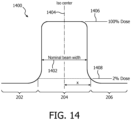
Fig. 14 shows an example of the spatial distribution of radiation from a radiation beam; -
Fig. 15 shows an embodiment of a medical apparatus; and -
Fig. 16 shows a flowchart which illustrates a method of operating the medical apparatus ofFig. 15 . - Like numbered elements in these figures are either equivalent elements or perform the same function. Elements which have been discussed previously will not necessarily be discussed in later figures if the function is equivalent.
- In some examples of a combined magnetic resonance (MR) imaging system and a LINAC, the receive coils or antenna of the MR LINAC system are placed as close as possible to the treated and imaged anatomy to maximize image quality and enable MR LINAC system to provide efficient MR guidance for the radiation beam. As a consequence, receive coils are located in the radiation beam path and this results that the coils attenuate and may cause non-idealities in the radiation therapy which may need to be taken into account in the delivery of the treatment. The receive coils are also exposed to relatively high radiation dose, that may affect the properties of the materials and electronics decreasing the overall lifetime of the coils.
- A coil that minimally disturbs the radiation beam and the operation of which is minimally affected by the irradiation is crucial in the MR Linac application.
- According to the invention, the MR antenna has an irradiation zone that enables radiation to pass through the coil minimally disturbing the dose delivery to the target or to other organs. The attenuation of the irradiation zone can be such that the attenuation can be neglected in the treatment planning. This streamlines user workflow and thus enables faster treatment planning and dose delivery.
- The irradiation zone of the coil increases the reliability of the coil in the high dose environment. The sensitive electronics and materials are not located within the zone, which minimizes the amount of accumulated dose in the sensitive parts over the lifetime of the coil.
- In some examples the irradiation zone within a receive coil can have one or more of the following elements:
- An area within the coil that is free of discrete electronic components
- An area that has minimized attenuation been made of low density materials, the structure construction can be rigid
- An area that has electrical conductors that minimally disturb the radiation beam
- A coil where the effect of radiation on the electronics is minimized by the placement and/or shielding.
-
Fig. 1 shows an example of amagnetic resonance antenna 100. In theantenna 100 is a composite made out of a variety of layers. InFig. 1 these layers are shown in an expanded view. There is anouter layer 102 that is in contact with a flexible printedcircuit board 104. The flexible printedcircuit board 104 contains the one or multiple antenna elements. The flexible printedcircuit board 104 is then connected to a coil former 106. The coil former 106 is a rigid foam or porous material. The coil former 106 is then connected to abiocompatible layer 108 that may be in contact with a subject. These four layers may be glued or laminated together to form a rigid magnetic resonance antenna. -
Fig. 2 shows theantenna 100 after it has been laminated together. Thecoil 100 is a surface coil that is a bit curved. On one side there is a first reducedradiation zone 202. In the middle of thecoil 100 there is airradiation zone 204. And on the other end there is a second reducedradiation zone 206. In theirradiation zone 204 there are no electronic components electronic components have been moved to the first reducedradiation zone 202 and the second reducedradiation zone 206. There is a perimeter about thisantenna 100. It can be seen there is afirst edge 208 and asecond edge 210 that are on opposite sides of theantenna 100. A cross-section or line can be drawn from thefirst edge 208 to thesecond edge 210 that stays within theirradiation zone 204. The antenna shown inFigs. 1 and 2 may be used in a LINAC system. The possible area where the beam may travel is aligned with theirradiation zone 204 and the electronics in the first 202 and second 206 reduced radiation zones are kept out of the X-ray beam path. - The irradiation zone of the structure is where the materials mentioned above create maximally homogenous area within the coil, i.e. may have no cutouts or other materials or components in it. This irradiation zone can be in the middle of the coil, or in one end of the coil. In case the irradiation zone is in one end of the coil, the coil can be used in combination with other similar coil. The irradiation zone placements within the coil are shown in
Figs. 8, 9, and 10 . The irradiation zone placed on the beam path has a length of greater than the radiation beam itself. - The magnetic resonance receive coil may have the feature of a mechanical structure of low density materials or foam that is rigid. The structure can be made of various alternative materials in a form sandwich that enhances the rigidity of the structure, as shown in
Fig. 1 . - The core of the structure is made of rigid, low density foam or material e.g. EPP (Expanded polypropylene). The material can be either machined or molded to its form. This part forms the basis for the structure in terms of rigidity. The density of the material is low, ~ 100 kg/m3.
- The outer surface of the structure is made of low density soft foam or material e.g. EVA (Ethylene-vinyl acetate). This foam or material is providing the biocompatible surface for the structure. Due to its closed cell structure, it also prevents liquids to ingress the structure. The material density is ~50 kg/ m3.
- In between the foam or material layers, the coil winding printed circuit board (PCB) is assembled. The foam or low density materials mentioned above and the PCB in between are thermo molded together to form the final structure and shape of the product. A thin layer of glue is attached between each layer to keep the layers firmly attached.
-
Fig. 3 shows across-sectional view 300 of amagnetic resonance antenna 100. In this case thecross-section 300 is a semi circle. Thefirst edge 208 and thesecond edge 210 could be placed on a centric support and the subject could be placed in the semi circle. From within thesemi circle 300 the cross-section is concave 302. A upview is shown inFig. 4 . The line marked 400 shows the location of thecross-section 300 shown inFig. 3 . The first reducedradiation zone 202 and the second reducedradiation zone 206 are also shown. In between the first 202 and the second 206 reduced radiation zone is theirradiation zone 204. There are four copperstrip antenna elements 404. Within the first reducedradiation zone 202 there are a number of pre-amplifiers andother electronics 402. The copper strips 404 are connected to the pre-amplifiers 402. Thecopper strip antennas 404 are very long and run the entire length of theantenna 100. - To make it easier to detune the
elements 404 when the antenna is not in the receive mode there is a number ofPIN diodes 406 and/or other electronics located in the second reducedradiation zone 206. ThesePIN diodes 406 are controlled by electronics in thepre-amplifier 402. There is aflat copper conductors 408 which act as a control for theelectronics 406. This enables the very long copperstrip antenna elements 404 to be detuned. Theflat copper conductors 408 are narrower than the copper strips 404. This means that their impedance at radio frequency are higher. This may enable thecontrol PIN diode 406 without interference from radio frequency signals from a magnetic resonance imaging system. -
Fig. 5 shows across-sectional view 500 which may be an alternative to that shown inFig. 3 . In this view the cross-sectional view is generally flat and rounded near theends -
Fig. 6 shows a furtheralternative cross-section 600. Thecross-section 600 may be used instead of thecross-section 300 shown inFig. 3 . In this cross-section there is a flat portion or straight with rounded edges near theends Fig. 6 there is a mixture of straight segments and curved or rounded segments. -
Fig. 7 shows an alternativecross-sectional view 700 it is an alternative to thecross-sectional view 300 shown inFig. 3 . In this cross-sectional view the cross-section is completely comprised of straight line segments. - It should be noted that in all cross-sectional views shown in
Fig. 3 ,Fig. 5, Fig. 6, and Fig. 7 they are all concave 302 with respect to where the subject would be placed. It may be advantageous to have the antennas be concave in this fashion because as the LINAC rotates the X-ray radiation source about the subject it reduces the amount of antenna that the radiation must pass through. This reduces the amount of attenuation by theantenna 100. - In various example there may be one or there may be several reduced radiation zones.
Figs. 8, 9 and 10 show several different examples. The examples shown inFigs. 8, 9 and 10 show straight cross-sections. However these straight cross-sections are only exemplary and the coils or antennas may be curved as is illustrated inFigs. 3 ,5, 6 and 7 . - In
Fig. 8 across-sectional view 800 of anantenna 100 is shown. The example is similar to that of the example shown inFig. 1 . There is anelectrical connection 802 going to a reducedradiation zone 202. Theirradiation zone 204 borders the reducedradiation zone 202. On the other side of the reducedirradiation zone 204 there is a second reducedradiation zone 206. - Another topology is shown in
Fig. 9 . InFig. 9 a furthercross-sectional view 900 of amagnetic resonance antenna 100 is shown. In this example there is anelectrical connection 802 going to a first reducedradiation zone 202. The reducedradiation zone 202 is in contact with theirradiation zone 204. -
Fig. 10 shows a further example of theantenna 100 thecross-sectional view 1000 is shown as having two complete sets of coils which border each other. There is anelectrical connection 802 going to the first reducedradiation zone 202 and there is a secondelectrical connection 802 going to the second reducedradiation zone 206. Theirradiation zone 204 is divided into two pieces which may have separate antenna elements. - Examples of magnetic resonace receive coils may also use Flex printed circuit board (PCB) for the coil elements made of thin radiation hard PCB substrates and thin and narrow copper traces for electrical connections. An example build-up for the PCB structure is shown in
Fig. 11 . The PCB is made of thin layers of Polyimide, which has good radiation hardness. -
Fig. 11 illustrates the stack of materials which may be used to form thestructure 1100 of a flexible printed circuit board suitable for examples. There is a top layer which is formed of polyimide this is connected with an adhesive to a copper layer which is then connected to another polyimide layer another adhesive layer and then a final polyimide layer. The first polyimide layer as shown is being as 13 micrometers thick. This for example may be between five and 25 micrometers. The various adhesive layers may be thicker or thinner. The copper layer is shown as being 18 micrometers. Copper layer thicknesses which work well may for example be between 18 and 35 micrometers thick. The copper is attached to a 125 micrometer polyimide layer. This may be thicker or thinner. For example, this polyimide layer may be between for example 25 to 200 micrometers thick. The lower polyimide layer is shown as being 13 micrometers. This for instance may be between 5 and 25 micrometers thick. - The copper traces that carry RF electromagnetic waves and DC current, are optimized minimally to shadow and attenuate the radiation beam within the irradiation zone. In some examples there may be different types of traces or conductors. For example: a) RF trace, purpose of which is to carry RF only; b) DC+RF trace, the purpose of which is to carry both DC and RF, and the DC trace is geometrically located on the left side of the RF trace; and c) RF + DC trace, the purpose of which is the same as in b) with exception that DC trace is right side oriented.
- Examples of magnetic resonance receive coils may also have the feature of distributed discrete electronic modules within the coil loop outside the irradiation zone. This optimizes MR performance of the receive coil during the radiation. This may be achieved by distributing multiple detune circuits with high impedance (Zdet) along the coil loop such way that total impedance during the transmit state of the system is high enough to prevent high transmit power to reduce coil performance. In
Fig. 12 and 13 this is shown the block diagram of two different loops with detune circuits and the irradiation zone. -
Fig. 12 shows a detune circuit for anantenna element 404. In the example shown inFig. 12 theirradiation zone 204 is between 2 202, 206 reduced radiation zones. Within the reducedirradiation zones detune circuits -
Fig. 13 shows a further example of anantenna element 404 with itsdetuned circuits 402. In this example there is only one reducedradiation zone 202 which is adjacent to theirradiation zone 204. - High impedance points within the loop, with an area of A, minimize the current flowing in the loop when the loop is exposed to high RF transmit field of B1. The induced voltage u is


- For a rectangular loop with width of a and length of b, the magnetic field in the center Bc is

- Where Iloop is the induced current in the loop

- The performance of the coil is not reduced when Bc ≤ 0.1 Bi then we can require that:


- These detune points are distributed in such a way that the irradiation zone length is maximized.
- o Distributing the coil preamplifiers away from the radiation beam path in such a way that the accumulated dose is minimal to enable high image quality over the lifetime. The distance of the preamplifier to the beam iso center x is selected in such a way that the dose due to the beam is in the order of 2% or lower at the location of preamplifier, see
Fig. 14 . - o Shielding the coil preamplifiers with materials with high radiation attenuation in such way that the dose at the preamplifier is in the order of 2% of the maximum beam dose.
-
Fig. 14 shows an example of the spatial distribution of radiation from aradiation beam 1400. The nominal beam width is labeled 1402. The beam isocenter is labeled 1404. The region of considered to be 100% dose is labeled 1406 and the region labeled 2% dose is labeled 1408. The region above 2% dose is considered to be theirradiation zone 204 and the two regions with 2% and less dose in this example are considered to be the first 202 and second 206 reduced radiation zones. -
Fig. 15 shows an example of amedical apparatus 1500 according to the invention. Themedical apparatus 1500 comprises aLINAC 202 and a magneticresonance imaging system 1504. TheLINAC 1502 comprises agantry 1506 and aX-ray source 1508. Thegantry 1506 is for rotating theX-ray source 1508 about an axis ofgantry rotation 1540. Adjacent to theX-ray source 1508 is anadjustable collimator 1510. Theadjustable collimator 1510 may for instance have adjustable plates for adjusting the beam profile of theX-ray source 1508. The adjustable collimator may, for example, be a multi-leaf collimator. The magneticresonance imaging system 1504 comprises amagnet 1512. - The
magnet 1512 shown inFig. 15 is only an example. It is also possible to use permanent or resistive magnets. The use of different types of magnets is also possible for instance it is also possible to use both a split cylindrical magnet and a so called open magnet. - A split cylindrical magnet is similar to a standard cylindrical magnet, except that the cryostat has been split into two sections to allow access to the iso-plane of the magnet, such magnets may for instance be used to provide a space for X-ray radiation to reach a subject 1536. An open magnet has two magnet sections, one above the other with a space in-between that is large enough to receive a subject: the arrangement of the two sections is similar to that of a Helmholtz coil. Open magnets are popular, because the subject is less confined. Inside the cryostat of the cylindrical magnet there is a collection of superconducting coils.
- The
magnet 1512 shown in this example is a modifed cylindrical superconducting magnet. Themagnet 1512 has acryostat 1514 with superconducting coils within it 1516. The magnet is designed such that aX-ray radiation beam 1542 does not intersect the superconducting coils 1516. The materials and thicknesses along thebeam path 1542 maybe chosen to reduce the attenuation of the X-ray radiation. As mentioned above a split or open magnet design may be used instead to eliminate the absorption of radiation by themagnet 1512. - The
magnet 1512 has abore 1522. Within thebore 1522 of thecylindrical magnet 1512 there is an imaging zone where the magnetic field is strong and uniform enough to perform magnetic resonance imaging. - Within the
bore 1522 of themagnet 1512 is a magneticfield gradient coil 1524 for acquisition of magnetic resonance data to spatially encode magnetic spins within an imaging zone of the magnet. The magneticfield gradient coil 1524 is connected to a magnetic field gradientcoil power supply 1526. The magneticfield gradient coil 1524 is intended to be representative, to allow radiation to pass through without being attenuated it will normally be a split-coil design. Typically magnetic field gradient coils contain three separate sets of coils for spatially encoding in three orthogonal spatial directions. The magnetic fieldgradient power supply 1526 supplies current to the magnetic field gradient coils. The current supplied to the magnetic field coils is controlled as a function of time and may be ramped or pulsed. - There is a
radio frequency coil 1528 connected to atransceiver 1530. Theradio frequency coil 1528 is adjacent to animaging zone 1532 of themagnet 1512. Theimaging zone 1532 has a region of high magnetic field and homogeneity which is sufficient for performing magnetic resonance imaging. Theradio frequency coil 1528 is for manipulating the orientations of magnetic spins within the imaging zone and possibly for receiving radio transmissions from spins also within the imaging zone. Theradio frequency coil 1528 may also be referred to as an antenna or channel. Theradio frequency coil 1528 may contain multiple coil elements. The radio frequency antenna may also be referred to as a channel. - The
radio frequency coil 1528 andradio frequency transceiver 1530 may be replaced by separate transmit and receive coils and a separate transmitter and receiver. It is understood that the radio frequency coil and the radio frequency transceiver are simply representative. The radio frequency antenna is intended to also represent a dedicated transmit antenna and a dedicated receive antenna. Likewise the transceiver may also represent a separate transmitter and receivers. - Also within the bore of the
magnet 1522 is asubject support 1534 for supporting a subject 1536. Thesubject support 1534 may be positioned by amechanical positioning system 1537. Within the subject 1536 there is atarget zone 1538. The axis ofgantry rotation 1540 is coaxial in this particular example with the cylindrical axis of themagnet 1512. Thesubject support 1534 has been positioned such that thetarget zone 1538 lies on theaxis 1540 of gantry rotation. TheX-ray source 1508 is shown as generating aradiation beam 1542 which passes through thecollimator 1510 and through thetarget zone 1538. As theradiation source 1508 is rotated about theaxis 1540 thetarget zone 1538 will always be targeted by theradiation beam 1542. Theradiation beam 1542 passes through thecryostat 1514 of the magnet. The magneticfield gradient coil 1524 has a gap 543 which separate the magnetic field gradient coil into two sections. Thegap 1543 reduced attenuation of theradiation beam 1542 by the magneticfield gradient coil 1524. Alternatively a split magnetic field gradient coil may be used. - A receive
magnetic resonance antenna 100 is placed over the subject 1536. In this example the receivemagnetic resonance antenna 100 has twomounts 1529 which attach theantenna 100 to thesubject support 1534 in with a controlled geometric relationship. This for example may be used to better estimate the dose received by the subject 1536. It can be seen that theradiation beam 1542 passes through theradiation zone 208 and for the most part avoids the first reducedradiation zone 202 and the second reducedradiation zone 206. - The transmit
coil 1528 may also be constructed similary to thecoil 100. Discrete components may be moved out side of the path of thebeam 1542. - The
transceiver 1530, the magnetic field gradientcoil power supply 1526 and themechanical positioning system 1537 are all shown as being connected to ahardware interface 1546 of acomputer system 1544. Thecomputer system 1544 is shown as further comprising aprocessor 1548 for executing machine executable instructions and for controlling the operation and function of the medical apparatus. Thehardware interface 1546 enables theprocessor 1548 to interact with and control themedical apparatus 1500. Theprocessor 1548 is shown as further being connected to auser interface 1550,computer storage 1552, andcomputer memory 1554. - The
computer storage 1552 is shown as containing atreatment plan 1560. Thecomputer storage 1552 is further shown as containing apulse sequence 1562. A pulse sequence as used herein is a set of commands used to control various components of the magneticresonance imaging system 1504 to acquiremagnetic resonance data 1564. Thecomputer storage 1552 is shown as containingmagnetic resonance data 1564 that was acquired using the magneticresonance imaging system 1504. - The
computer storage 1552 is further shown as containing amagnetic resonance image 1566 that was reconstructed from themagnetic resonance data 1564. Thecomputer storage 1552 is further shown as containing animage registration 1568 of themagnetic resonance image 1566. Theimage registration 1568 registers the location of the image relative to the magneticresonance imaging system 1504 and theLINAC 1502. Thecomputer storage 1552 is further shown as containing thelocation 1570 of thetarget zone 1538. This was identified in themagnetic resonance image 1566. Thecomputer storage 1552 is further shown as containing control signals 1572. The control signals 1572 are control signals which are used to control theLINAC 1502 to irradiate thetarget zone 1538. - The computer memory is shown as containing a
control module 1580. The control module contains computer-executable code which enables theprocessor 1548 to control the operation and function of themedical apparatus 1500. For instance thecontrol module 1580 may use the pulse sequence1562 to acquire themagnetic resonance data 1564. Thecontrol module 1580 may also use thecontrol signals 1572 to control theLINAC 1502. Thecomputer memory 1554 is further shown as containing a treatmentplan modification module 1582. The treatmentplan modification module 1582 modifies the treatment plan 1558 using theimage registration 1568. Thecomputer memory 1554 is shown as further containing animage reconstruction module 1584. Theimage reconstruction module 1584 contains code which enables theprocessor 1548 to reconstruct themagnetic resonance image 1566 from themagnetic resonance data 1564. - The
computer memory 1554 is shown as further containing animage registration module 1586. Theimage registration module 1586 contains code which enables theprocessor 1548 to generate theimage registration 1568 in the location of the target zone 272 using themagnetic resonance image 1566. Thecomputer memory 1554 is shown as further containing a targetzone location module 1588. The targetzone location module 1588 contains code which enables theprocessor 1548 to generate the location of thetarget zone 1570 using theimage registration 1568. Thecomputer memory 1554 is further shown as containing a control signal generation module 290. The control signal generation module 290 contains code which enables theprocessor 1548 to generate thecontrol signals 1572 from thetreatment plan 1560 and the location of thetarget zone 1570. Thetreatment plan 1560 after it has been modified. -
Fig. 16 shows a flowchart which illustrates a method of operating themedical apparatus 1500 ofFig. 15 . In step 1600 atreatment plan 1560 is received. In step 1602 a processor controls the magneticresonance imaging system 1504 to acquire themagnetic resonance data 1564. Next instep 1604 the processor reconstructs themagnetic resonance image 1566 from themagnetic resonance data 1564. Next instep 1606 the processor registers the location of thetarget zone 1570 and themagnetic resonance image 1566. This creates animage registration 1568. Next instep 1572 the processor generates thecontrol signals 1572 using the location of thetarget zone 1570 and thetreatment plan 1560. The processor likely also references a model of theapparatus 1560 to generate the correct commands. Finally instep 1610 the processor controls the X-ray radiation source of the LINAC to irradiate thetarget zone 1538 using the control signals 1572. - While the invention has been illustrated and described in detail in the drawings and foregoing description, such illustration and description are to be considered illustrative or exemplary and not restrictive; the invention is defined by the claims and not limited to the disclosed embodiments.
- Other variations to the disclosed embodiments can be understood and effected by those skilled in the art in practicing the claimed invention, from a study of the drawings, the disclosure, and the appended claims. In the claims, the word "comprising" does not exclude other elements or steps, and the indefinite article "a" or "an" does not exclude a plurality. A single processor or other unit may fulfill the functions of several items recited in the claims. The mere fact that certain measures are recited in mutually different dependent claims does not indicate that a combination of these measured cannot be used to advantage. A computer program may be stored/distributed on a suitable medium, such as an optical storage medium or a solid-state medium supplied together with or as part of other hardware, but may also be distributed in other forms, such as via the Internet or other wired or wireless telecommunication systems. Any reference signs in the claims should not be construed as limiting the scope.
-
- 100
- magnetic resonance antenna
- 102
- outer layer
- 104
- flexible printed circuit board
- 106
- coil former
- 108
- biocompatible layer
- 202
- first reduced radiation zone
- 204
- irradiation zone
- 206
- second reduced radiation zone
- 208
- first edge
- 210
- second edge
- 300
- cross sectional view
- 302
- concave surface
- 400
- cross section
- 402
- preamplifier and other electronics
- 404
- coper strips of antenna elements
- 406
- PIN diode and other electronics
- 408
- flat coper conductors
- 500
- cross sectional view
- 600
- cross sectional view
- 700
- cross sectional view
- 800
- cross sectional view
- 802
- electrical connection
- 900
- cross sectional view
- 1000
- cross sectional view
- 1100
- structure of printed circuit board
- 1400
- X-ray radiation beam
- 1402
- nominal beam width
- 1404
- iso center
- 1406
- 100% dose
- 1408
- 2% dose
- 1500
- mecical apparatus
- 1502
- LINAC
- 1504
- magnetic resonance imaging system
- 1506
- gantry
- 1508
- X-ray source
- 1510
- adjustable collimator
- 1512
- magnet
- 1514
- cryostat
- 1516
- superconducting coil
- 1522
- bore
- 1524
- magnetic field gradient coil
- 1526
- magnetic field gradient coil power supply
- 1528
- transmit antenna
- 1530
- transciever
- 1532
- imaging zone
- 1534
- subject support
- 1536
- subject
- 1537
- mechanical positioning system
- 1538
- target zone
- 1540
- axis of gantry rotation
- 1542
- radiation beam
- 1543
- gap
- 1544
- computer system
- 1546
- hardware interface
- 1548
- processor
- 1550
- user interface
- 1552
- computer storage
- 1554
- computer memory
- 1560
- treatment plan
- 1562
- pulse sequence
- 1564
- magnetic resonance data
- 1566
- magnetic resonance image
- 1568
- image registration
- 1570
- location of target zone
- 1572
- control signals
- 1580
- control module
- 1582
- treatment plan modification module
- 1584
- image reconstruction module
- 1586
- image registration module
- 1588
- target zone location module
- 1590
- control signal generation module
- 1600
- receive a treatment plan for irradiating the target zone
- 1602
- acquire the magnetic resonance data using the magnetic resonance imaging system
- 1604
- reconstruct a magnetic resonance image from the magnetic resonance data
- 1606
- register a location of the target zone in the magnetic resonance image
- 1608
- generate control signals in accordance with the location of the target zone and the treatment plan
- 1610
- control the X-ray radiation source of the LINAC to irradiate the target zone using the control signals
Claims (12)
- A medical instrument (1500) comprising:- a LINAC (1502) with an X-ray source (1508) configured for directing X-ray radiation (1542) at a target zone (1538), wherein the LINAC is adapted for rotating the X-ray source about a rotational axis (1540); and- a magnetic resonance imaging system (1502) configured for acquiring magnetic resonance data (1564) with a magnetic resonance antenna (100) from an imaging zone (1532), wherein the target zone is within the imaging zone, wherein the magnetic resonance imaging system comprises a magnet (1512) configured for generating a magnetic field within the imaging zone, wherein the X-ray source is adapted for rotating at least partially about the magnet;
wherein the magnetic resonance imaging system comprises the magnetic resonance antenna (100), wherein the magnetic resonance antenna is a surface coil, wherein the magnetic resonance antenna is a receive coil, wherein the magnetic resonance antenna comprises:- an antenna element (104, 404)- a preamplifier (402) for the antenna element; and- a coil former (106) configured for supporting the antenna element, wherein the coil former is formed from a porous material, wherein the coil former is rigid, wherein the coil former is divided into an irradiation zone (204) and at least one reduced radiation zone (202, 206), wherein the irradiation zone is configured to enable the X-ray radiation to pass through the magnetic resonance antenna while minimally disturbing an X-ray radiation dose delivery to the target zone,
wherein the preamplifier for the antenna element is located within the at least one reduced radiation zone, wherein the antenna element is located at least partially within the irradiation zone, wherein the coil former has a perimeter, wherein the irradiation zone extends continuously from a first edge (208) of the perimeter to a second edge (210) of the perimeter, and wherein the first edge and the second edge are opposing edges. - The medical instrument of claim 1, wherein the porous material is any one of the following: a foam, expanded polypropylene, Polyutethane foam, Polyimide foam, PEEK foam, a corrugated structure, corrugated cardboard, and a honeycomb structure and/or has an attenuation of less than 2 percent for X-ray radiation between 1.8 MeV and 8 MeV.
- The medical instrument of claim 1 or 2, wherein a cross section of the coil former from the first edge to the second edge is predominantly convex when observed from a direction (302) from the coil former to the antenna element.
- The medical instrument of claim 3, wherein the cross section is any one of the following: a semi-circle (300), comprising straight segments and rounded segments (600), generally flat with rounded portions near the first edge and the second edge (500), and a series of connected straight segments (700).
- The medical instrument of any one of the preceding claims, wherein the coil former comprises one or more mounting fixtures (1529) for attaching the magnetic resonance antenna to a subject support (1534).
- The medical instrument of any one of the preceding claims, wherein the antenna element is formed on a flexible printed circuit board, wherein the flexible printed circuit is attached to the coil former.
- The medical instrument of any one of the preceding claims, comprising multiple antenna elements, wherein the at least one reduced radiation zone is two or more reduced radiation zones, wherein the two or more reduced radiation zones comprise PIN diodes (402, 406) for controlling detuning of the multiple antenna elements, wherein the irradiation zone comprises conductors for carrying electrical signals between the two or more reduced radiation zones for controlling the switching of the PIN diodes.
- The medical instrument of any one of the preceding claims, wherein the magnetic resonance antenna has a first surface (108) and a second surface (102), wherein the coil former is between the first surface and the antenna element, wherein the antenna element is between the second surface and the coil former, wherein the magnetic resonance antenna further comprises:- a biocompatible (108) layer that forms the first surface and- an outer layer (102) that forms the second surface.
- The medical instrument of claim 8, wherein the biocompatible layer is any one of the following: Ethylene-vinyl acetate, polyurethane, polyamide foam, PEEK foam, and PVC foam and/or the outer layer is any one of the following: Ethylene-vinyl acetate, PVC foam, and polyurethane, PEEK foam, and PVC foam.
- The medical instrument of claim 8 or 9, wherein the biocompatible layer is laminated to the coil former and/or wherein the biocompatible layer is laminated to the antenna element.
- The medical instrument of any one of the preceding claims, wherein the thickness of the porous material is uniform.
- The medical instrument of any one of the preceding claims, wherein the medical instrument further comprises:- a processor (1548) configured for controlling the medical instrument:- a memory (1554) storing machine executable instructions (1580, 1582. 1584, 1586, 1588, 1590) for execution by the processor, wherein execution of the machine executable instructions causes the processor to:- receive (1600) a treatment plan (1560) for irradiating the target zone;- acquire (1602) the magnetic resonance data (1564) using the magnetic resonance imaging system;- reconstruct (1604) a magnetic resonance image (1566) from the magnetic resonance data;- register (1606) a location (1570) of the target zone in the magnetic resonance image;- generate (1608) control signals (1572) in accordance with the location of the target zone and the treatment plan; and- control (1610) the LINAC to irradiate the target zone using the control signals.
Applications Claiming Priority (2)
| Application Number | Priority Date | Filing Date | Title |
|---|---|---|---|
| EP14183088 | 2014-09-01 | ||
| PCT/EP2015/068258 WO2016034364A1 (en) | 2014-09-01 | 2015-08-07 | Magnetic resonance imaging receive coil with reduced radiation attenuation |
Publications (2)
| Publication Number | Publication Date |
|---|---|
| EP3194997A1 EP3194997A1 (en) | 2017-07-26 |
| EP3194997B1 true EP3194997B1 (en) | 2023-10-11 |
Family
ID=51429150
Family Applications (1)
| Application Number | Title | Priority Date | Filing Date |
|---|---|---|---|
| EP15750366.5A Active EP3194997B1 (en) | 2014-09-01 | 2015-08-07 | Magnetic resonance imaging receive coil with reduced radiation attenuation |
Country Status (5)
| Country | Link |
|---|---|
| US (1) | US10718831B2 (en) |
| EP (1) | EP3194997B1 (en) |
| JP (1) | JP6605021B2 (en) |
| CN (1) | CN106922173B (en) |
| WO (1) | WO2016034364A1 (en) |
Families Citing this family (13)
| Publication number | Priority date | Publication date | Assignee | Title |
|---|---|---|---|---|
| DE102015201462B3 (en) * | 2015-01-28 | 2016-05-12 | Siemens Aktiengesellschaft | High frequency coil unit for magnetic resonance imaging |
| DE102016212421A1 (en) * | 2016-07-07 | 2018-01-11 | Siemens Healthcare Gmbh | Cable arrangement for use in an MR local coil |
| US10391335B2 (en) * | 2017-03-02 | 2019-08-27 | Ingham Institute for Applied Medical Research | Radio-frequency coil for simultaneous imaging and dosimetry on an MRI-linac |
| DE102017206368A1 (en) * | 2017-04-13 | 2018-10-18 | Siemens Aktiengesellschaft | A coil base for producing an eddy current sensor, an eddy current sensor and a device for winding a coil wire on the coil main body for producing such an eddy current sensor |
| JP7150415B2 (en) | 2017-04-27 | 2022-10-11 | コーニンクレッカ フィリップス エヌ ヴェ | Medical device for magnetic resonance imaging guided radiation therapy |
| EP3412243A1 (en) * | 2017-06-08 | 2018-12-12 | Servicio Andaluz De Salud | Rigid pvc foam sheets for use in radiotherapy and/or diagnosis imaging |
| EP3428671A1 (en) | 2017-07-11 | 2019-01-16 | Koninklijke Philips N.V. | Rf feed circuit for magnetic resonance imaging |
| US11883685B2 (en) | 2017-08-24 | 2024-01-30 | Shanghai United Imaging Healthcare Co., Ltd. | Therapeutic system and method |
| CN109420259A (en) | 2017-08-24 | 2019-03-05 | 上海联影医疗科技有限公司 | Treatment system and the method for using treatment system |
| WO2019102020A1 (en) * | 2017-11-27 | 2019-05-31 | Koninklijke Philips N.V. | Mesh networks in wireless mri rf coil |
| EP3553546A1 (en) * | 2018-04-09 | 2019-10-16 | Koninklijke Philips N.V. | Automatic positioning of antenna connectors for magnetic resonance imaging |
| CN109001656B (en) * | 2018-04-28 | 2019-07-19 | 中国科学院深圳先进技术研究院 | A kind of flexible radio frequency receiving coil array |
| CN113253174B (en) * | 2021-05-13 | 2023-06-16 | 上海联影医疗科技股份有限公司 | Receiving antenna assembly and magnetic resonance device |
Family Cites Families (14)
| Publication number | Priority date | Publication date | Assignee | Title |
|---|---|---|---|---|
| US6060882A (en) * | 1995-12-29 | 2000-05-09 | Doty Scientific, Inc. | Low-inductance transverse litz foil coils |
| US7526330B1 (en) * | 2004-07-06 | 2009-04-28 | Pulseteq Limited | Magnetic resonance scanning apparatus |
| US7394254B2 (en) * | 2005-04-27 | 2008-07-01 | The Board Of Trustees Of The Leland Stanford Junior University | Magnetic resonance imaging having radiation compatible radiofrequency coils |
| JP5179820B2 (en) * | 2006-10-27 | 2013-04-10 | 株式会社東芝 | High frequency coil device |
| EP2192871B8 (en) * | 2007-09-24 | 2015-01-28 | MRI Interventions, Inc. | Mri-compatible patch and method for identifying a position |
| DE102009023806B4 (en) * | 2008-07-09 | 2011-04-28 | Siemens Aktiengesellschaft | Combined PET-MR device, component and local coil |
| DE102008046974B4 (en) * | 2008-09-12 | 2013-12-19 | Siemens Aktiengesellschaft | Local coil device for magnetic resonance tomography device |
| AU2010273298B2 (en) * | 2009-07-15 | 2014-10-23 | Viewray Technologies, Inc. | Method and apparatus for shielding a linear accelerator and a magnetic resonance imaging device from each other |
| DE102009043446B4 (en) * | 2009-09-29 | 2013-08-01 | Siemens Aktiengesellschaft | Magnetic resonance system with a variable in its geometry local coil array |
| US8604789B2 (en) * | 2010-04-30 | 2013-12-10 | Imris Inc. | RF coil assembly for use in magnetic resonance imaging |
| WO2012063162A1 (en) * | 2010-11-09 | 2012-05-18 | Koninklijke Philips Electronics N.V. | Magnetic resonance imaging and radiotherapy apparatus with at least two-transmit-and receive channels |
| US9081067B2 (en) * | 2011-05-09 | 2015-07-14 | Imris Inc. | Phased array MR RF coil which is not visible in X-ray image |
| US8797030B2 (en) * | 2011-07-28 | 2014-08-05 | General Electric Company | Magnetic resonance radio-frequency coil and method of manufacturing |
| JP6001177B2 (en) | 2012-09-18 | 2016-10-05 | コーニンクレッカ フィリップス エヌ ヴェKoninklijke Philips N.V. | Linear accelerator guided by magnetic resonance |
-
2015
- 2015-08-07 US US15/505,259 patent/US10718831B2/en active Active
- 2015-08-07 CN CN201580058853.3A patent/CN106922173B/en active Active
- 2015-08-07 WO PCT/EP2015/068258 patent/WO2016034364A1/en active Application Filing
- 2015-08-07 JP JP2017511187A patent/JP6605021B2/en active Active
- 2015-08-07 EP EP15750366.5A patent/EP3194997B1/en active Active
Also Published As
| Publication number | Publication date |
|---|---|
| EP3194997A1 (en) | 2017-07-26 |
| CN106922173A (en) | 2017-07-04 |
| JP6605021B2 (en) | 2019-11-13 |
| US10718831B2 (en) | 2020-07-21 |
| JP2017529147A (en) | 2017-10-05 |
| US20170252578A1 (en) | 2017-09-07 |
| WO2016034364A1 (en) | 2016-03-10 |
| CN106922173B (en) | 2021-03-23 |
Similar Documents
| Publication | Publication Date | Title |
|---|---|---|
| EP3194997B1 (en) | Magnetic resonance imaging receive coil with reduced radiation attenuation | |
| US10307616B2 (en) | Medical apparatus with a radiation therapy device and a radiation detection system | |
| US9504851B2 (en) | Magnetic resonance imaging of bone tissue | |
| EP2638409B1 (en) | Magnetic resonance imaging and radiotherapy apparatus with at least two-transmit-and receive channels | |
| US10022104B2 (en) | Markers, phantoms and associated methods for calibrating imaging systems | |
| CN103260701B (en) | Radiation therapy planning and tracking system using the CT and magnetic resonance imaging of the core of big chamber thorax and magnetic resonance imaging or big chamber thorax | |
| US10099070B2 (en) | Medical apparatus for radiotherapy and ultrasound heating | |
| US9608395B2 (en) | Slip ring assembly | |
| CN109983356A (en) | Medical image system including magnet unit and radiating element | |
| Kron et al. | Magnetic resonance imaging for adaptive cobalt tomotherapy: A proposal | |
| US11229376B2 (en) | Medical instrument for magnetic resonance imaging guided radiotherapy | |
| JP6965261B2 (en) | MR Visible Markers for MRI Devices and MR Guided Radiation Therapy Systems | |
| Majewski et al. | Compact and mobile high resolution PET brain imager | |
| Baldock | Medical Imaging–X-rays |
Legal Events
| Date | Code | Title | Description |
|---|---|---|---|
| STAA | Information on the status of an ep patent application or granted ep patent |
Free format text: STATUS: THE INTERNATIONAL PUBLICATION HAS BEEN MADE |
|
| PUAI | Public reference made under article 153(3) epc to a published international application that has entered the european phase |
Free format text: ORIGINAL CODE: 0009012 |
|
| STAA | Information on the status of an ep patent application or granted ep patent |
Free format text: STATUS: REQUEST FOR EXAMINATION WAS MADE |
|
| 17P | Request for examination filed |
Effective date: 20170403 |
|
| AK | Designated contracting states |
Kind code of ref document: A1 Designated state(s): AL AT BE BG CH CY CZ DE DK EE ES FI FR GB GR HR HU IE IS IT LI LT LU LV MC MK MT NL NO PL PT RO RS SE SI SK SM TR |
|
| AX | Request for extension of the european patent |
Extension state: BA ME |
|
| DAV | Request for validation of the european patent (deleted) | ||
| DAX | Request for extension of the european patent (deleted) | ||
| RAP1 | Party data changed (applicant data changed or rights of an application transferred) |
Owner name: KONINKLIJKE PHILIPS N.V. |
|
| STAA | Information on the status of an ep patent application or granted ep patent |
Free format text: STATUS: EXAMINATION IS IN PROGRESS |
|
| 17Q | First examination report despatched |
Effective date: 20210409 |
|
| STAA | Information on the status of an ep patent application or granted ep patent |
Free format text: STATUS: EXAMINATION IS IN PROGRESS |
|
| GRAP | Despatch of communication of intention to grant a patent |
Free format text: ORIGINAL CODE: EPIDOSNIGR1 |
|
| STAA | Information on the status of an ep patent application or granted ep patent |
Free format text: STATUS: GRANT OF PATENT IS INTENDED |
|
| INTG | Intention to grant announced |
Effective date: 20230420 |
|
| GRAS | Grant fee paid |
Free format text: ORIGINAL CODE: EPIDOSNIGR3 |
|
| GRAA | (expected) grant |
Free format text: ORIGINAL CODE: 0009210 |
|
| STAA | Information on the status of an ep patent application or granted ep patent |
Free format text: STATUS: THE PATENT HAS BEEN GRANTED |
|
| AK | Designated contracting states |
Kind code of ref document: B1 Designated state(s): AL AT BE BG CH CY CZ DE DK EE ES FI FR GB GR HR HU IE IS IT LI LT LU LV MC MK MT NL NO PL PT RO RS SE SI SK SM TR |
|
| REG | Reference to a national code |
Ref country code: GB Ref legal event code: FG4D |
|
| REG | Reference to a national code |
Ref country code: CH Ref legal event code: EP |
|
| REG | Reference to a national code |
Ref country code: DE Ref legal event code: R096 Ref document number: 602015086058 Country of ref document: DE |
|
| REG | Reference to a national code |
Ref country code: IE Ref legal event code: FG4D |
|
| REG | Reference to a national code |
Ref country code: DE Ref legal event code: R084 Ref document number: 602015086058 Country of ref document: DE |
|
| REG | Reference to a national code |
Ref country code: LT Ref legal event code: MG9D |
|
| REG | Reference to a national code |
Ref country code: NL Ref legal event code: MP Effective date: 20231011 |
|
| REG | Reference to a national code |
Ref country code: AT Ref legal event code: MK05 Ref document number: 1620727 Country of ref document: AT Kind code of ref document: T Effective date: 20231011 |
|
| PG25 | Lapsed in a contracting state [announced via postgrant information from national office to epo] |
Ref country code: NL Free format text: LAPSE BECAUSE OF FAILURE TO SUBMIT A TRANSLATION OF THE DESCRIPTION OR TO PAY THE FEE WITHIN THE PRESCRIBED TIME-LIMIT Effective date: 20231011 |
|
| PG25 | Lapsed in a contracting state [announced via postgrant information from national office to epo] |
Ref country code: GR Free format text: LAPSE BECAUSE OF FAILURE TO SUBMIT A TRANSLATION OF THE DESCRIPTION OR TO PAY THE FEE WITHIN THE PRESCRIBED TIME-LIMIT Effective date: 20240112 |
|
| PG25 | Lapsed in a contracting state [announced via postgrant information from national office to epo] |
Ref country code: IS Free format text: LAPSE BECAUSE OF FAILURE TO SUBMIT A TRANSLATION OF THE DESCRIPTION OR TO PAY THE FEE WITHIN THE PRESCRIBED TIME-LIMIT Effective date: 20240211 |
|
| REG | Reference to a national code |
Ref country code: GB Ref legal event code: 746 Effective date: 20240314 |
|
| PG25 | Lapsed in a contracting state [announced via postgrant information from national office to epo] |
Ref country code: LT Free format text: LAPSE BECAUSE OF FAILURE TO SUBMIT A TRANSLATION OF THE DESCRIPTION OR TO PAY THE FEE WITHIN THE PRESCRIBED TIME-LIMIT Effective date: 20231011 |
|
| PG25 | Lapsed in a contracting state [announced via postgrant information from national office to epo] |
Ref country code: AT Free format text: LAPSE BECAUSE OF FAILURE TO SUBMIT A TRANSLATION OF THE DESCRIPTION OR TO PAY THE FEE WITHIN THE PRESCRIBED TIME-LIMIT Effective date: 20231011 |