JP2019535424A - System and method for automatic detection in magnetic resonance imaging - Google Patents
System and method for automatic detection in magnetic resonance imaging Download PDFInfo
- Publication number
- JP2019535424A JP2019535424A JP2019527297A JP2019527297A JP2019535424A JP 2019535424 A JP2019535424 A JP 2019535424A JP 2019527297 A JP2019527297 A JP 2019527297A JP 2019527297 A JP2019527297 A JP 2019527297A JP 2019535424 A JP2019535424 A JP 2019535424A
- Authority
- JP
- Japan
- Prior art keywords
- image data
- patient
- magnetic resonance
- brain
- change
- Prior art date
- Legal status (The legal status is an assumption and is not a legal conclusion. Google has not performed a legal analysis and makes no representation as to the accuracy of the status listed.)
- Ceased
Links
Images


Classifications
-
- G—PHYSICS
- G01—MEASURING; TESTING
- G01R—MEASURING ELECTRIC VARIABLES; MEASURING MAGNETIC VARIABLES
- G01R33/00—Arrangements or instruments for measuring magnetic variables
- G01R33/20—Arrangements or instruments for measuring magnetic variables involving magnetic resonance
- G01R33/44—Arrangements or instruments for measuring magnetic variables involving magnetic resonance using nuclear magnetic resonance [NMR]
- G01R33/48—NMR imaging systems
- G01R33/54—Signal processing systems, e.g. using pulse sequences ; Generation or control of pulse sequences; Operator console
- G01R33/56—Image enhancement or correction, e.g. subtraction or averaging techniques, e.g. improvement of signal-to-noise ratio and resolution
- G01R33/5608—Data processing and visualization specially adapted for MR, e.g. for feature analysis and pattern recognition on the basis of measured MR data, segmentation of measured MR data, edge contour detection on the basis of measured MR data, for enhancing measured MR data in terms of signal-to-noise ratio by means of noise filtering or apodization, for enhancing measured MR data in terms of resolution by means for deblurring, windowing, zero filling, or generation of gray-scaled images, colour-coded images or images displaying vectors instead of pixels
-
- A—HUMAN NECESSITIES
- A61—MEDICAL OR VETERINARY SCIENCE; HYGIENE
- A61B—DIAGNOSIS; SURGERY; IDENTIFICATION
- A61B5/00—Measuring for diagnostic purposes; Identification of persons
- A61B5/0048—Detecting, measuring or recording by applying mechanical forces or stimuli
- A61B5/0055—Detecting, measuring or recording by applying mechanical forces or stimuli by applying suction
-
- A—HUMAN NECESSITIES
- A61—MEDICAL OR VETERINARY SCIENCE; HYGIENE
- A61B—DIAGNOSIS; SURGERY; IDENTIFICATION
- A61B5/00—Measuring for diagnostic purposes; Identification of persons
- A61B5/0033—Features or image-related aspects of imaging apparatus classified in A61B5/00, e.g. for MRI, optical tomography or impedance tomography apparatus; arrangements of imaging apparatus in a room
- A61B5/004—Features or image-related aspects of imaging apparatus classified in A61B5/00, e.g. for MRI, optical tomography or impedance tomography apparatus; arrangements of imaging apparatus in a room adapted for image acquisition of a particular organ or body part
- A61B5/0042—Features or image-related aspects of imaging apparatus classified in A61B5/00, e.g. for MRI, optical tomography or impedance tomography apparatus; arrangements of imaging apparatus in a room adapted for image acquisition of a particular organ or body part for the brain
-
- A—HUMAN NECESSITIES
- A61—MEDICAL OR VETERINARY SCIENCE; HYGIENE
- A61B—DIAGNOSIS; SURGERY; IDENTIFICATION
- A61B5/00—Measuring for diagnostic purposes; Identification of persons
- A61B5/05—Detecting, measuring or recording for diagnosis by means of electric currents or magnetic fields; Measuring using microwaves or radio waves
- A61B5/055—Detecting, measuring or recording for diagnosis by means of electric currents or magnetic fields; Measuring using microwaves or radio waves involving electronic [EMR] or nuclear [NMR] magnetic resonance, e.g. magnetic resonance imaging
-
- A—HUMAN NECESSITIES
- A61—MEDICAL OR VETERINARY SCIENCE; HYGIENE
- A61B—DIAGNOSIS; SURGERY; IDENTIFICATION
- A61B5/00—Measuring for diagnostic purposes; Identification of persons
- A61B5/40—Detecting, measuring or recording for evaluating the nervous system
- A61B5/4058—Detecting, measuring or recording for evaluating the nervous system for evaluating the central nervous system
- A61B5/4064—Evaluating the brain
-
- A—HUMAN NECESSITIES
- A61—MEDICAL OR VETERINARY SCIENCE; HYGIENE
- A61B—DIAGNOSIS; SURGERY; IDENTIFICATION
- A61B5/00—Measuring for diagnostic purposes; Identification of persons
- A61B5/72—Signal processing specially adapted for physiological signals or for diagnostic purposes
- A61B5/7235—Details of waveform analysis
- A61B5/7264—Classification of physiological signals or data, e.g. using neural networks, statistical classifiers, expert systems or fuzzy systems
- A61B5/7267—Classification of physiological signals or data, e.g. using neural networks, statistical classifiers, expert systems or fuzzy systems involving training the classification device
-
- G—PHYSICS
- G01—MEASURING; TESTING
- G01R—MEASURING ELECTRIC VARIABLES; MEASURING MAGNETIC VARIABLES
- G01R33/00—Arrangements or instruments for measuring magnetic variables
- G01R33/20—Arrangements or instruments for measuring magnetic variables involving magnetic resonance
- G01R33/28—Details of apparatus provided for in groups G01R33/44 - G01R33/64
- G01R33/38—Systems for generation, homogenisation or stabilisation of the main or gradient magnetic field
- G01R33/3806—Open magnet assemblies for improved access to the sample, e.g. C-type or U-type magnets
-
- G—PHYSICS
- G01—MEASURING; TESTING
- G01R—MEASURING ELECTRIC VARIABLES; MEASURING MAGNETIC VARIABLES
- G01R33/00—Arrangements or instruments for measuring magnetic variables
- G01R33/20—Arrangements or instruments for measuring magnetic variables involving magnetic resonance
- G01R33/44—Arrangements or instruments for measuring magnetic variables involving magnetic resonance using nuclear magnetic resonance [NMR]
- G01R33/445—MR involving a non-standard magnetic field B0, e.g. of low magnitude as in the earth's magnetic field or in nanoTesla spectroscopy, comprising a polarizing magnetic field for pre-polarisation, B0 with a temporal variation of its magnitude or direction such as field cycling of B0 or rotation of the direction of B0, or spatially inhomogeneous B0 like in fringe-field MR or in stray-field imaging
-
- G—PHYSICS
- G01—MEASURING; TESTING
- G01R—MEASURING ELECTRIC VARIABLES; MEASURING MAGNETIC VARIABLES
- G01R33/00—Arrangements or instruments for measuring magnetic variables
- G01R33/20—Arrangements or instruments for measuring magnetic variables involving magnetic resonance
- G01R33/44—Arrangements or instruments for measuring magnetic variables involving magnetic resonance using nuclear magnetic resonance [NMR]
- G01R33/48—NMR imaging systems
- G01R33/4806—Functional imaging of brain activation
-
- G—PHYSICS
- G01—MEASURING; TESTING
- G01R—MEASURING ELECTRIC VARIABLES; MEASURING MAGNETIC VARIABLES
- G01R33/00—Arrangements or instruments for measuring magnetic variables
- G01R33/20—Arrangements or instruments for measuring magnetic variables involving magnetic resonance
- G01R33/44—Arrangements or instruments for measuring magnetic variables involving magnetic resonance using nuclear magnetic resonance [NMR]
- G01R33/48—NMR imaging systems
- G01R33/483—NMR imaging systems with selection of signals or spectra from particular regions of the volume, e.g. in vivo spectroscopy
-
- G—PHYSICS
- G06—COMPUTING; CALCULATING OR COUNTING
- G06F—ELECTRIC DIGITAL DATA PROCESSING
- G06F18/00—Pattern recognition
- G06F18/20—Analysing
- G06F18/24—Classification techniques
- G06F18/241—Classification techniques relating to the classification model, e.g. parametric or non-parametric approaches
- G06F18/2411—Classification techniques relating to the classification model, e.g. parametric or non-parametric approaches based on the proximity to a decision surface, e.g. support vector machines
-
- G—PHYSICS
- G06—COMPUTING; CALCULATING OR COUNTING
- G06F—ELECTRIC DIGITAL DATA PROCESSING
- G06F18/00—Pattern recognition
- G06F18/20—Analysing
- G06F18/24—Classification techniques
- G06F18/241—Classification techniques relating to the classification model, e.g. parametric or non-parametric approaches
- G06F18/2413—Classification techniques relating to the classification model, e.g. parametric or non-parametric approaches based on distances to training or reference patterns
- G06F18/24133—Distances to prototypes
- G06F18/24143—Distances to neighbourhood prototypes, e.g. restricted Coulomb energy networks [RCEN]
-
- G—PHYSICS
- G06—COMPUTING; CALCULATING OR COUNTING
- G06T—IMAGE DATA PROCESSING OR GENERATION, IN GENERAL
- G06T7/00—Image analysis
- G06T7/0002—Inspection of images, e.g. flaw detection
- G06T7/0012—Biomedical image inspection
-
- G—PHYSICS
- G06—COMPUTING; CALCULATING OR COUNTING
- G06T—IMAGE DATA PROCESSING OR GENERATION, IN GENERAL
- G06T7/00—Image analysis
- G06T7/0002—Inspection of images, e.g. flaw detection
- G06T7/0012—Biomedical image inspection
- G06T7/0014—Biomedical image inspection using an image reference approach
- G06T7/0016—Biomedical image inspection using an image reference approach involving temporal comparison
-
- G—PHYSICS
- G06—COMPUTING; CALCULATING OR COUNTING
- G06V—IMAGE OR VIDEO RECOGNITION OR UNDERSTANDING
- G06V10/00—Arrangements for image or video recognition or understanding
- G06V10/70—Arrangements for image or video recognition or understanding using pattern recognition or machine learning
- G06V10/764—Arrangements for image or video recognition or understanding using pattern recognition or machine learning using classification, e.g. of video objects
-
- G—PHYSICS
- G06—COMPUTING; CALCULATING OR COUNTING
- G06V—IMAGE OR VIDEO RECOGNITION OR UNDERSTANDING
- G06V10/00—Arrangements for image or video recognition or understanding
- G06V10/70—Arrangements for image or video recognition or understanding using pattern recognition or machine learning
- G06V10/82—Arrangements for image or video recognition or understanding using pattern recognition or machine learning using neural networks
-
- A—HUMAN NECESSITIES
- A61—MEDICAL OR VETERINARY SCIENCE; HYGIENE
- A61B—DIAGNOSIS; SURGERY; IDENTIFICATION
- A61B2576/00—Medical imaging apparatus involving image processing or analysis
- A61B2576/02—Medical imaging apparatus involving image processing or analysis specially adapted for a particular organ or body part
- A61B2576/026—Medical imaging apparatus involving image processing or analysis specially adapted for a particular organ or body part for the brain
-
- G—PHYSICS
- G01—MEASURING; TESTING
- G01R—MEASURING ELECTRIC VARIABLES; MEASURING MAGNETIC VARIABLES
- G01R33/00—Arrangements or instruments for measuring magnetic variables
- G01R33/20—Arrangements or instruments for measuring magnetic variables involving magnetic resonance
- G01R33/28—Details of apparatus provided for in groups G01R33/44 - G01R33/64
- G01R33/38—Systems for generation, homogenisation or stabilisation of the main or gradient magnetic field
- G01R33/383—Systems for generation, homogenisation or stabilisation of the main or gradient magnetic field using permanent magnets
-
- G—PHYSICS
- G06—COMPUTING; CALCULATING OR COUNTING
- G06N—COMPUTING ARRANGEMENTS BASED ON SPECIFIC COMPUTATIONAL MODELS
- G06N3/00—Computing arrangements based on biological models
- G06N3/02—Neural networks
- G06N3/04—Architecture, e.g. interconnection topology
- G06N3/044—Recurrent networks, e.g. Hopfield networks
-
- G—PHYSICS
- G06—COMPUTING; CALCULATING OR COUNTING
- G06N—COMPUTING ARRANGEMENTS BASED ON SPECIFIC COMPUTATIONAL MODELS
- G06N3/00—Computing arrangements based on biological models
- G06N3/02—Neural networks
- G06N3/04—Architecture, e.g. interconnection topology
- G06N3/045—Combinations of networks
-
- G—PHYSICS
- G06—COMPUTING; CALCULATING OR COUNTING
- G06T—IMAGE DATA PROCESSING OR GENERATION, IN GENERAL
- G06T2207/00—Indexing scheme for image analysis or image enhancement
- G06T2207/10—Image acquisition modality
- G06T2207/10072—Tomographic images
- G06T2207/10088—Magnetic resonance imaging [MRI]
-
- G—PHYSICS
- G06—COMPUTING; CALCULATING OR COUNTING
- G06T—IMAGE DATA PROCESSING OR GENERATION, IN GENERAL
- G06T2207/00—Indexing scheme for image analysis or image enhancement
- G06T2207/20—Special algorithmic details
- G06T2207/20081—Training; Learning
-
- G—PHYSICS
- G06—COMPUTING; CALCULATING OR COUNTING
- G06T—IMAGE DATA PROCESSING OR GENERATION, IN GENERAL
- G06T2207/00—Indexing scheme for image analysis or image enhancement
- G06T2207/20—Special algorithmic details
- G06T2207/20084—Artificial neural networks [ANN]
-
- G—PHYSICS
- G06—COMPUTING; CALCULATING OR COUNTING
- G06T—IMAGE DATA PROCESSING OR GENERATION, IN GENERAL
- G06T2207/00—Indexing scheme for image analysis or image enhancement
- G06T2207/20—Special algorithmic details
- G06T2207/20092—Interactive image processing based on input by user
-
- G—PHYSICS
- G06—COMPUTING; CALCULATING OR COUNTING
- G06T—IMAGE DATA PROCESSING OR GENERATION, IN GENERAL
- G06T2207/00—Indexing scheme for image analysis or image enhancement
- G06T2207/20—Special algorithmic details
- G06T2207/20212—Image combination
-
- G—PHYSICS
- G06—COMPUTING; CALCULATING OR COUNTING
- G06T—IMAGE DATA PROCESSING OR GENERATION, IN GENERAL
- G06T2207/00—Indexing scheme for image analysis or image enhancement
- G06T2207/30—Subject of image; Context of image processing
- G06T2207/30004—Biomedical image processing
- G06T2207/30016—Brain
-
- G—PHYSICS
- G06—COMPUTING; CALCULATING OR COUNTING
- G06T—IMAGE DATA PROCESSING OR GENERATION, IN GENERAL
- G06T2207/00—Indexing scheme for image analysis or image enhancement
- G06T2207/30—Subject of image; Context of image processing
- G06T2207/30004—Biomedical image processing
- G06T2207/30101—Blood vessel; Artery; Vein; Vascular
-
- G—PHYSICS
- G06—COMPUTING; CALCULATING OR COUNTING
- G06T—IMAGE DATA PROCESSING OR GENERATION, IN GENERAL
- G06T2207/00—Indexing scheme for image analysis or image enhancement
- G06T2207/30—Subject of image; Context of image processing
- G06T2207/30172—Centreline of tubular or elongated structure
-
- G—PHYSICS
- G06—COMPUTING; CALCULATING OR COUNTING
- G06V—IMAGE OR VIDEO RECOGNITION OR UNDERSTANDING
- G06V2201/00—Indexing scheme relating to image or video recognition or understanding
- G06V2201/03—Recognition of patterns in medical or anatomical images
- G06V2201/031—Recognition of patterns in medical or anatomical images of internal organs
-
- G—PHYSICS
- G16—INFORMATION AND COMMUNICATION TECHNOLOGY [ICT] SPECIALLY ADAPTED FOR SPECIFIC APPLICATION FIELDS
- G16H—HEALTHCARE INFORMATICS, i.e. INFORMATION AND COMMUNICATION TECHNOLOGY [ICT] SPECIALLY ADAPTED FOR THE HANDLING OR PROCESSING OF MEDICAL OR HEALTHCARE DATA
- G16H30/00—ICT specially adapted for the handling or processing of medical images
- G16H30/40—ICT specially adapted for the handling or processing of medical images for processing medical images, e.g. editing
-
- G—PHYSICS
- G16—INFORMATION AND COMMUNICATION TECHNOLOGY [ICT] SPECIALLY ADAPTED FOR SPECIFIC APPLICATION FIELDS
- G16H—HEALTHCARE INFORMATICS, i.e. INFORMATION AND COMMUNICATION TECHNOLOGY [ICT] SPECIALLY ADAPTED FOR THE HANDLING OR PROCESSING OF MEDICAL OR HEALTHCARE DATA
- G16H50/00—ICT specially adapted for medical diagnosis, medical simulation or medical data mining; ICT specially adapted for detecting, monitoring or modelling epidemics or pandemics
- G16H50/70—ICT specially adapted for medical diagnosis, medical simulation or medical data mining; ICT specially adapted for detecting, monitoring or modelling epidemics or pandemics for mining of medical data, e.g. analysing previous cases of other patients
Abstract
いくつかの側面は、患者の脳における正中線偏位の度合いの変化を検出する方法を含む。患者が低磁場磁気共鳴撮像装置内に位置されたままである間に、患者の脳の第一の磁気共鳴(MR)画像データおよび第二のMR画像データを取得し;前記第一および第二のMRデータを、トレーニングされた統計的分類器に入力として提供して、対応する第一および第二の出力を得て;前記第一の出力から、患者の脳の少なくとも一つの正中線構造に関連する少なくとも一つの目印の少なくとも一つの初期位置を識別し;前記第二の出力から、前記少なくとも一つの目印の少なくとも一つの更新された位置を識別し;前記少なくとも一つの目印の前記少なくとも一つの初期位置と前記少なくとも一つの目印の前記少なくとも一つの更新された位置とを使って前記正中線偏位における変化の度合いを決定する。Some aspects include methods of detecting a change in the degree of midline excursion in a patient's brain. Acquiring first magnetic resonance (MR) image data and second MR image data of the patient's brain while the patient remains positioned in the low field magnetic resonance imaging device; MR data is provided as an input to a trained statistical classifier to obtain corresponding first and second outputs; from said first output, related to at least one midline structure of a patient's brain Identifying at least one initial position of the at least one landmark; identifying from the second output at least one updated position of the at least one landmark; the at least one initial position of the at least one landmark. Using a location and the at least one updated location of the at least one landmark to determine a degree of change in the midline deviation.
Description
本願は、2016年11月22日に出願された「変化の検出方法および装置」と題する米国仮出願第62/425,569号の米国特許法第119条(e)のもとでの利益を主張する。同出願の内容はここに参照によってその全体において組み込まれる。 This application claims benefit under 35 USC 119 (e) of US Provisional Application No. 62 / 425,569 entitled "Method and Apparatus for Detecting Change" filed Nov. 22, 2016. . The contents of that application are hereby incorporated by reference in their entirety.
磁気共鳴撮像(MRI)は、数多くの用途のための重要な撮像モダリティーであり、人体内部の画像を生成するために臨床および研究の場面において幅広く利用されている。MRIは磁気共鳴(MR)信号を検出することに基づく。磁気共鳴信号は、加えられた電磁場の結果として生じる状態変化に応答して原子によって放出される電磁波である。たとえば、核磁気共鳴(NMR)技法は、撮像されるオブジェクトにおける原子(たとえば人体の組織内の原子)の核スピンの再整列または緩和の際に励起された原子の核から放出されるMR信号を検出することに関わる。検出されたMR信号は処理されて画像を生成してもよい。該画像は、医療用途の文脈では、診断、治療および/または研究目的のために体内の内部構造および/または生体過程の調査を許容する。 Magnetic resonance imaging (MRI) is an important imaging modality for many applications and is widely used in clinical and research settings to generate images inside the human body. MRI is based on detecting magnetic resonance (MR) signals. A magnetic resonance signal is an electromagnetic wave emitted by an atom in response to a state change that occurs as a result of an applied electromagnetic field. For example, nuclear magnetic resonance (NMR) techniques are used to generate MR signals emitted from the nuclei of excited atoms upon realignment or relaxation of the nuclear spins of atoms in the object being imaged (eg, atoms in a human tissue). Involved in detecting. The detected MR signal may be processed to generate an image. The images allow investigation of internal structures and / or biological processes in the body for diagnostic, therapeutic and / or research purposes in the context of medical applications.
MRIは、他のモダリティーの安全上の懸念なしに(たとえば被験体を電離放射線、たとえばX線にさらしたり体内に放射性物質を導入したりする必要なしに)比較的高い分解能およびコントラストをもつ非侵襲的な画像を生成できるため、生体撮像のための魅力的な撮像モダリティーを提供する。さらに、MRIは、他の撮像モダリティーが満足いくように撮像できない主題を撮像するために活用できる軟組織コントラストを提供するのに特に好適である。さらに、MR技法は、他の撮像モダリティーが取得できない構造および/または生体過程についての情報を捕捉することができる。しかしながら、通常のMRI技法にはいくつかの欠点がある。それは、所与の撮像用途について、相対的に高い設備費用、限られた可用性(たとえば臨床MRIスキャナへのアクセスを得ることの困難および費用)、画像取得プロセスの長さなどを含みうる。 MRI is non-invasive with relatively high resolution and contrast without the safety concerns of other modalities (eg, without having to expose the subject to ionizing radiation, eg, X-rays or introduce radioactive material into the body) An attractive imaging modality for in vivo imaging is provided. Furthermore, MRI is particularly well suited to providing soft tissue contrast that can be exploited to image subjects that cannot be imaged satisfactorily by other imaging modalities. In addition, MR techniques can capture information about structures and / or biological processes that other imaging modalities cannot obtain. However, conventional MRI techniques have several drawbacks. It may include relatively high equipment costs, limited availability (eg, difficulty and cost of obtaining access to a clinical MRI scanner), length of image acquisition process, etc. for a given imaging application.
臨床MRIにおける潮流は、スキャン時間、画像分解能および画像コントラストの一つまたは複数を改善するためにMRIスキャナの磁場強度を高めることであったが、それはMRI撮像の費用を押し上げる。大半の設置されているMRIスキャナは少なくとも1.5または3テスラ(T)で動作する。これはスキャナの主磁場B0の磁場強度をいう。臨床MRIスキャナについての大まかな推定費用はテスラ当たり百万ドルのオーダーである。これは、そのようなMRIスキャナを運用することに関わるかなりの運用、サービスおよびメンテナンス費用は考慮に入れてもいない。 The trend in clinical MRI has been to increase the magnetic field strength of the MRI scanner to improve one or more of scan time, image resolution and image contrast, which pushes the cost of MRI imaging. Most installed MRI scanners operate at least 1.5 or 3 Tesla (T). This refers to the field strength of the main magnetic field B 0 of the scanner. A rough estimate for clinical MRI scanners is on the order of $ 1 million per Tesla. This does not take into account the considerable operational, service and maintenance costs associated with operating such an MRI scanner.
さらに、通常の高磁場MRIシステムは典型的には、その中で対象(たとえば患者)が撮像される強い一様な静磁場(B0)を生成するために大きな超伝導磁石および付随する電子回路系を必要とする。超伝導磁石はさらに、導体を超伝導状態に保つために低温設備を必要とする。そのようなシステムのサイズは、磁気コンポーネント、電子回路系、熱管理システムおよび制御コンソール領域のために複数の部屋(MRIシステムの磁気コンポーネントを隔離するために特別に遮蔽された部屋を含む)を含む典型的なMRI設備ではかなりのものである。MRIシステムのサイズおよび費用は一般にその使用を、病院および学術研究センターのような、MRIシステムを購入して維持する十分なスペースおよびリソースをもつ施設に限定する。高磁場MRIシステムの高いコストおよび実質的なスペース要件は、MRIスキャナの限られた可用性につながる。よって、MRIスキャンが有益なのに上記の制限のために実際的でないまたは不可能である臨床状況がよくある。これについては下記でさらに論じる。 In addition, conventional high field MRI systems typically have large superconducting magnets and associated electronic circuitry to generate a strong uniform static magnetic field (B 0 ) within which the subject (eg, patient) is imaged. Requires a system. Superconducting magnets further require low temperature equipment to keep the conductors in a superconducting state. The size of such systems includes multiple rooms for magnetic components, electronic circuitry, thermal management systems and control console areas, including rooms that are specifically shielded to isolate the magnetic components of the MRI system A typical MRI facility is quite substantial. The size and cost of MRI systems generally limit their use to facilities with sufficient space and resources to purchase and maintain MRI systems, such as hospitals and academic research centers. The high cost and substantial space requirements of high field MRI systems lead to the limited availability of MRI scanners. Thus, there are often clinical situations where MRI scans are beneficial but impractical or impossible due to the above limitations. This is discussed further below.
いくつかの実施形態は、低磁場磁気共鳴撮像(MRI)装置内に位置される患者の脳における正中線偏位の度合いの変化を検出する方法に向けられる。本方法は:患者が前記低磁場MRI装置内に位置されたままである間に:患者の脳の第一の磁気共鳴(MR)画像データを取得し;前記第一のMRデータを入力として、トレーニングされた統計的分類器に提供して、対応する第一の出力を得て;前記第一の出力から、患者の脳の少なくとも一つの正中線構造に関連する少なくとも一つの目印の少なくとも一つの初期位置を識別し;前記第一のMR画像データを取得した後に患者の脳の第二のMR画像データを取得し;前記第二のMR画像データを入力として、前記トレーニングされた統計的分類器に提供して、対応する第二の出力を得て;前記第二の出力から、患者の脳の前記少なくとも一つの正中線構造に関連する前記少なくとも一つの目印の少なくとも一つの更新された位置を識別し;前記少なくとも一つの目印の前記少なくとも一つの初期位置と前記少なくとも一つの目印の前記少なくとも一つの更新された位置とを使って前記正中線偏位における変化の度合いを決定することを含む。 Some embodiments are directed to methods of detecting changes in the degree of midline excursions in a patient's brain located within a low field magnetic resonance imaging (MRI) device. The method: While the patient remains positioned in the low field MRI apparatus: acquiring first magnetic resonance (MR) image data of the patient's brain; training with the first MR data as input And providing a corresponding first output; from said first output, at least one initial of at least one landmark associated with at least one midline structure of the patient's brain Identifying a position; obtaining a second MR image data of a patient's brain after obtaining the first MR image data; taking the second MR image data as an input to the trained statistical classifier; Providing a corresponding second output; identifying from the second output at least one updated position of the at least one landmark associated with the at least one midline structure of the patient's brain Said at least one Using the at least one initial position of the landmark and the at least one updated position of the at least one landmark to determine a degree of change in the midline deviation.
いくつかの実施形態は、低磁場磁気共鳴撮像(MRI)装置内に位置される患者の脳における正中線偏位の度合いの変化を検出するよう構成された低磁場磁気共鳴撮像装置に向けられる。前記低磁場MRI装置は:少なくとも部分的にB0磁場を生成するよう構成されたB0磁石;磁気共鳴データを空間的にエンコードするよう構成された少なくとも一つの傾斜磁石;および磁気共鳴応答を誘発するよう構成された少なくとも一つの高周波コイルおよび動作させられたときに磁気共鳴画像データを取得するよう構成された検出磁気コンポーネントを含む複数の磁気コンポーネントと;患者が当該低磁場磁気共鳴撮像装置内に位置されたままである間に、患者の脳の第一の磁気共鳴(MR)画像データを取得し、前記第一のMR画像データを取得した後に患者の脳の第二のMR画像データを取得するよう前記複数の磁気コンポーネントを動作させるよう構成された少なくとも一つのコントローラとを有し、前記少なくとも一つのコントローラはさらに:前記第一および第二のMR画像データを入力として、トレーニングされた統計的分類器に提供して、対応する第一の出力および第二の出力を得て;前記第一の出力から、患者の脳の少なくとも一つの正中線構造に関連する少なくとも一つの目印の少なくとも一つの初期位置を識別し;前記第二の出力から、患者の脳の前記少なくとも一つの正中線構造に関連する前記少なくとも一つの目印の少なくとも一つの更新された位置を識別し;前記少なくとも一つの目印の前記少なくとも一つの初期位置と前記少なくとも一つの目印の前記少なくとも一つの更新された位置とを使って前記正中線偏位における変化の度合いを決定することを実行するよう構成される。 Some embodiments are directed to a low field magnetic resonance imaging device configured to detect a change in the degree of midline excursion in a patient's brain located within a low field magnetic resonance imaging (MRI) device. The low field MRI apparatus includes: a B0 magnet configured to at least partially generate a B0 magnetic field; at least one gradient magnet configured to spatially encode magnetic resonance data; and to induce a magnetic resonance response A plurality of magnetic components including at least one high frequency coil configured and a sensing magnetic component configured to acquire magnetic resonance image data when operated; and a patient is located within the low field magnetic resonance imaging device To obtain first magnetic resonance (MR) image data of the patient's brain while remaining, and to obtain second MR image data of the patient's brain after obtaining the first MR image data At least one controller configured to operate a plurality of magnetic components, the at least one controller further Providing the first and second MR image data as input to a trained statistical classifier to obtain corresponding first and second outputs; from the first output, the patient Identifying at least one initial position of at least one landmark associated with at least one midline structure of the brain of the patient; from the second output, Identifying at least one updated position of one landmark; using the at least one initial position of the at least one landmark and the at least one updated position of the at least one landmark; Is configured to perform determining the degree of change in.
いくつかの実施形態は、少なくとも一つのコンピュータ・ハードウェア・プロセッサによって実行されたときに該少なくとも一つのコンピュータ・ハードウェア・プロセッサに、低磁場磁気共鳴撮像(MRI)装置内に位置される患者の脳における正中線偏位の度合いの変化を検出する方法を実行させるプロセッサ実行可能命令を記憶している少なくとも一つの非一時的コンピュータ可読記憶媒体に向けられる。前記方法は:患者が前記低磁場MRI装置内に位置されたままである間に:患者の脳の第一の磁気共鳴(MR)画像データを取得し;前記第一のMRデータを入力として、トレーニングされた統計的分類器に提供して、対応する第一の出力を得て;前記第一の出力から、患者の脳の少なくとも一つの正中線構造に関連する少なくとも一つの目印の少なくとも一つの初期位置を識別し;前記第一のMR画像データを取得した後に患者の脳の第二のMR画像データを取得し;前記第二のMR画像データを入力として、前記トレーニングされた統計的分類器に提供して、対応する第二の出力を得て;前記第二の出力から、患者の脳の前記少なくとも一つの正中線構造に関連する前記少なくとも一つの目印の少なくとも一つの更新された位置を識別し;前記少なくとも一つの目印の前記少なくとも一つの初期位置と前記少なくとも一つの目印の前記少なくとも一つの更新された位置とを使って前記正中線偏位における変化の度合いを決定することを含む。 Some embodiments include a patient located in a low field magnetic resonance imaging (MRI) device on at least one computer hardware processor when executed by at least one computer hardware processor. It is directed to at least one non-transitory computer readable storage medium that stores processor-executable instructions for performing a method for detecting a change in the degree of midline deviation in the brain. The method includes: acquiring a first magnetic resonance (MR) image data of the patient's brain while the patient remains in the low field MRI apparatus; training with the first MR data as input And providing a corresponding first output; from said first output, at least one initial of at least one landmark associated with at least one midline structure of the patient's brain Identifying the position; obtaining the second MR image data of the patient's brain after obtaining the first MR image data; taking the second MR image data as an input to the trained statistical classifier; Providing a corresponding second output; identifying from the second output at least one updated position of the at least one landmark associated with the at least one midline structure of the patient's brain And at least one Determining the degree of change in the midline deviation using the at least one initial position of a landmark and the at least one updated position of the at least one landmark.
いくつかの実施形態は、少なくとも一つのコンピュータ・ハードウェア・プロセッサと、前記少なくとも一つのコンピュータ・ハードウェア・プロセッサによって実行されたときに前記少なくとも一つのコンピュータ・ハードウェア・プロセッサに、低磁場磁気共鳴撮像(MRI)装置内に位置される患者の脳における正中線偏位の度合いの変化を検出する方法を実行させるプロセッサ実行可能命令を記憶している少なくとも一つの非一時的コンピュータ可読記憶媒体とを有するシステムに向けられる。前記方法は:患者が前記低磁場MRI装置内に位置されたままである間に:患者の脳の第一の磁気共鳴(MR)画像データを取得し;前記第一のMRデータを入力として、トレーニングされた統計的分類器に提供して、対応する第一の出力を得て;前記第一の出力から、患者の脳の少なくとも一つの正中線構造に関連する少なくとも一つの目印の少なくとも一つの初期位置を識別し;前記第一のMR画像データを取得した後に患者の脳の第二のMR画像データを取得し;前記第二のMR画像データを入力として、前記トレーニングされた統計的分類器に提供して、対応する第二の出力を得て;前記第二の出力から、患者の脳の前記少なくとも一つの正中線構造に関連する前記少なくとも一つの目印の少なくとも一つの更新された位置を識別し;前記少なくとも一つの目印の前記少なくとも一つの初期位置と前記少なくとも一つの目印の前記少なくとも一つの更新された位置とを使って前記正中線偏位における変化の度合いを決定することを含む。 Some embodiments provide at least one computer hardware processor and low field magnetic resonance to the at least one computer hardware processor when executed by the at least one computer hardware processor. At least one non-transitory computer-readable storage medium storing processor-executable instructions for performing a method for detecting a change in the degree of midline deviation in a patient's brain located within an imaging (MRI) device; Directed to the system that has. The method includes: acquiring a first magnetic resonance (MR) image data of the patient's brain while the patient remains in the low field MRI apparatus; training with the first MR data as input And providing a corresponding first output; from said first output, at least one initial of at least one landmark associated with at least one midline structure of the patient's brain Identifying the position; obtaining the second MR image data of the patient's brain after obtaining the first MR image data; taking the second MR image data as an input to the trained statistical classifier; Providing a corresponding second output; identifying from the second output at least one updated position of the at least one landmark associated with the at least one midline structure of the patient's brain And at least one Determining the degree of change in the midline deviation using the at least one initial position of a landmark and the at least one updated position of the at least one landmark.
いくつかの実施形態は、低磁場磁気共鳴撮像(MRI)装置内に位置される患者の脳における異常のサイズの変化を判別する方法に向けられる。本方法は:患者が前記低磁場MRI装置内に位置されたままである間に:患者の脳の第一の磁気共鳴(MR)画像データを取得し;前記第一のMR画像データを入力として、トレーニングされた統計的分類器に提供して、対応する第一の出力を得て;前記第一の出力を使って、患者の脳における異常のサイズを示す少なくとも一つの特徴の少なくとも一つの初期値を同定し;前記第一のMR画像データを取得した後に患者の脳の第二のMR画像データを取得し;前記第二のMR画像データを入力として、前記トレーニングされた統計的分類器に提供して、対応する第二の出力を得て;前記第二の出力を使って、患者の脳における前記異常のサイズを示す前記少なくとも一つの特徴の少なくとも一つの更新された値を同定し;前記少なくとも一つの特徴の前記少なくとも一つの初期値と前記少なくとも一つの特徴の前記少なくとも一つの更新された値とを使って前記異常のサイズの変化を決定することを含む。 Some embodiments are directed to a method of determining a change in size of an abnormality in a patient's brain located within a low field magnetic resonance imaging (MRI) device. The method comprises: obtaining a first magnetic resonance (MR) image data of the patient's brain while the patient remains positioned in the low field MRI apparatus; Providing to a trained statistical classifier to obtain a corresponding first output; using said first output, at least one initial value of at least one feature indicative of the size of the abnormality in the patient's brain Obtaining second MR image data of the patient's brain after obtaining the first MR image data; providing the second MR image data as input to the trained statistical classifier Obtaining a corresponding second output; using the second output to identify at least one updated value of the at least one characteristic indicative of the size of the abnormality in the patient's brain; Said at least one of the features Determining a change in size of the anomaly using at least one initial value and the at least one updated value of the at least one feature.
いくつかの実施形態は、患者の脳における異常のサイズの変化を判別するよう構成された低磁場磁気共鳴撮像(MRI)装置に向けられる。本低磁場MRI装置は:少なくとも部分的にB0磁場を生成するよう構成されたB0磁石;磁気共鳴データを空間的にエンコードするよう構成された少なくとも一つの傾斜磁石;および磁気共鳴応答を誘発するよう構成された少なくとも一つの高周波コイルおよび動作させられたときに磁気共鳴画像データを取得するよう構成された検出磁気コンポーネントを含む複数の磁気コンポーネントと;患者が前記低磁場磁気共鳴装置内に位置されたままである間に:患者の脳の第一の磁気共鳴(MR)画像データを取得し、前記第一のMR画像データを取得した後に患者の脳の第二のMR画像データを取得するよう前記複数の磁石コンポーネントを動作させるよう構成された少なくとも一つのコントローラとを有する。前記少なくとも一つのコントローラはさらに:前記第一および第二のMR画像データを入力として、トレーニングされた統計的分類器に提供して、対応する第一の出力および第二の出力を得て;前記第一の出力を使って、患者の脳における異常のサイズを示す少なくとも一つの特徴の少なくとも一つの初期値を同定し;前記第一のMR画像データを取得した後に患者の脳の前記部分についての第二のMR画像データを取得し;前記第二の出力を使って、患者の脳における前記異常のサイズを示す前記少なくとも一つの特徴の少なくとも一つの更新された値を同定し;前記少なくとも一つの特徴の前記少なくとも一つの初期値と前記少なくとも一つの特徴の前記少なくとも一つの更新された値とを使って前記異常のサイズの変化を決定することを実行するよう構成される。 Some embodiments are directed to a low field magnetic resonance imaging (MRI) device configured to determine a change in size of an abnormality in a patient's brain. The low field MRI apparatus includes: a B0 magnet configured to at least partially generate a B0 magnetic field; at least one gradient magnet configured to spatially encode magnetic resonance data; and to induce a magnetic resonance response A plurality of magnetic components including at least one high frequency coil configured and a sensing magnetic component configured to acquire magnetic resonance image data when activated; and a patient is positioned within the low field magnetic resonance apparatus. In between: acquiring the first magnetic resonance (MR) image data of the patient's brain, and acquiring the second MR image data of the patient's brain after acquiring the first MR image data At least one controller configured to operate a plurality of magnet components. The at least one controller further: providing the first and second MR image data as inputs to a trained statistical classifier to obtain corresponding first and second outputs; The first output is used to identify at least one initial value of at least one feature indicative of the size of the abnormality in the patient's brain; after obtaining the first MR image data, for the portion of the patient's brain Obtaining second MR image data; using the second output to identify at least one updated value of the at least one feature indicative of the size of the abnormality in the patient's brain; Performing a change in size of the anomaly using the at least one initial value of the feature and the at least one updated value of the at least one feature; As constructed.
いくつかの実施形態は、少なくとも一つのコンピュータ・ハードウェア・プロセッサによって実行されたときに該少なくとも一つのコンピュータ・ハードウェア・プロセッサに、低磁場磁気共鳴撮像(MRI)装置内に位置される患者の脳における異常のサイズの変化を判別する方法を実行させるプロセッサ実行可能命令を記憶している少なくとも一つの非一時的コンピュータ可読記憶媒体に向けられる。前記方法は:患者が前記低磁場MRI装置内に位置されたままである間に:患者の脳の第一の磁気共鳴(MR)画像データを取得し;前記第一のMR画像データを入力として、トレーニングされた統計的分類器に提供して、対応する第一の出力を得て;前記第一の出力を使って、患者の脳における異常のサイズを示す少なくとも一つの特徴の少なくとも一つの初期値を同定し;前記第一のMR画像データを取得した後に患者の脳の第二のMR画像データを取得し;前記第二のMR画像データを入力として、前記トレーニングされた統計的分類器に提供して、対応する第二の出力を得て;前記第二の出力を使って、患者の脳における前記異常のサイズを示す前記少なくとも一つの特徴の少なくとも一つの更新された値を同定し;前記少なくとも一つの特徴の前記少なくとも一つの初期値と前記少なくとも一つの特徴の前記少なくとも一つの更新された値とを使って前記異常のサイズの変化を決定することを含む。 Some embodiments include a patient located in a low field magnetic resonance imaging (MRI) device on at least one computer hardware processor when executed by at least one computer hardware processor. At least one non-transitory computer-readable storage medium storing processor-executable instructions for performing a method for determining a change in the size of an abnormality in the brain. The method includes: obtaining a first magnetic resonance (MR) image data of the patient's brain while the patient remains positioned in the low field MRI apparatus; Providing to a trained statistical classifier to obtain a corresponding first output; using said first output, at least one initial value of at least one feature indicative of the size of the abnormality in the patient's brain Obtaining second MR image data of the patient's brain after obtaining the first MR image data; providing the second MR image data as input to the trained statistical classifier Obtaining a corresponding second output; using the second output to identify at least one updated value of the at least one characteristic indicative of the size of the abnormality in the patient's brain; Said small quantity of at least one feature Determining a change in size of the anomaly using at least one initial value and the at least one updated value of the at least one feature.
いくつかの実施形態は、少なくとも一つのコンピュータ・ハードウェア・プロセッサと、前記少なくとも一つのコンピュータ・ハードウェア・プロセッサによって実行されたときに前記少なくとも一つのコンピュータ・ハードウェア・プロセッサに、低磁場磁気共鳴撮像(MRI)装置内に位置される患者の脳における異常のサイズの変化を判別する方法を実行させるプロセッサ実行可能命令を記憶している少なくとも一つの非一時的コンピュータ可読記憶媒体とを有するシステムに向けられる。前記方法は:患者が前記低磁場MRI装置内に位置されたままである間に:患者の脳の第一の磁気共鳴(MR)画像データを取得し;前記第一のMR画像データを入力として、トレーニングされた統計的分類器に提供して、対応する第一の出力を得て;前記第一の出力を使って、患者の脳における異常のサイズを示す少なくとも一つの特徴の少なくとも一つの初期値を同定し;前記第一のMR画像データを取得した後に患者の脳の第二のMR画像データを取得し;前記第二のMR画像データを入力として、前記トレーニングされた統計的分類器に提供して、対応する第二の出力を得て;前記第二の出力を使って、患者の脳における前記異常のサイズを示す前記少なくとも一つの特徴の少なくとも一つの更新された値を同定し;前記少なくとも一つの特徴の前記少なくとも一つの初期値と前記少なくとも一つの特徴の前記少なくとも一つの更新された値とを使って前記異常のサイズの変化を決定することを含む。 Some embodiments provide at least one computer hardware processor and low field magnetic resonance to the at least one computer hardware processor when executed by the at least one computer hardware processor. A system having at least one non-transitory computer-readable storage medium storing processor-executable instructions for performing a method of determining a change in size of an abnormality in a patient's brain located within an imaging (MRI) device Directed. The method includes: obtaining a first magnetic resonance (MR) image data of the patient's brain while the patient remains positioned in the low field MRI apparatus; Providing to a trained statistical classifier to obtain a corresponding first output; using said first output, at least one initial value of at least one feature indicative of the size of the abnormality in the patient's brain Obtaining second MR image data of the patient's brain after obtaining the first MR image data; providing the second MR image data as input to the trained statistical classifier Obtaining a corresponding second output; using the second output to identify at least one updated value of the at least one characteristic indicative of the size of the abnormality in the patient's brain; Said small quantity of at least one feature Determining a change in size of the anomaly using at least one initial value and the at least one updated value of the at least one feature.
いくつかの実施形態は、低磁場磁気共鳴撮像(MRI)装置内に位置される患者の生物学的主題における変化を検出する方法に向けられる。本方法は:患者が前記低磁場MRI装置内に位置されたままである間に:患者の一部分の第一の磁気共鳴画像データを取得し;前記第一の磁気共鳴画像データを取得した後に患者の前記部分の第二の磁気共鳴画像データを取得し;前記第一の磁気共鳴画像データおよび前記第二の磁気共鳴画像データを整列させ;整列された第一の磁気共鳴画像データおよび第二の磁気共鳴画像データを比較して、患者の前記部分の前記生物学的主題における少なくとも一つの変化を検出することを含む。 Some embodiments are directed to methods of detecting changes in a patient's biological subject located within a low field magnetic resonance imaging (MRI) device. The method includes: acquiring a first magnetic resonance image data of a portion of the patient; and acquiring the first magnetic resonance image data after acquiring the first magnetic resonance image data while the patient remains positioned in the low-field MRI apparatus. Obtaining the second magnetic resonance image data of the portion; aligning the first magnetic resonance image data and the second magnetic resonance image data; aligning the first magnetic resonance image data and the second magnetic resonance image data; Comparing the resonance image data to detect at least one change in the biological subject of the portion of the patient.
いくつかの実施形態は、低磁場磁気共鳴撮像装置に関して位置される患者の生物学的主題における変化を検出するよう構成された低磁場磁気共鳴撮像装置に向けられる。本装置は:少なくとも部分的にB0磁場を生成するよう構成されたB0磁石;磁気共鳴データを空間的にエンコードするよう構成された少なくとも一つの傾斜磁石;および磁気共鳴応答を誘発するよう構成された少なくとも一つの高周波コイルおよび動作させられたときに磁気共鳴画像データを取得するよう構成された検出磁気コンポーネントを含む複数の磁気コンポーネントと;患者が前記低磁場磁気共鳴装置内に位置されたままである間に:患者の一部分の第一の磁気共鳴画像データを取得し;前記第一の磁気共鳴画像データを取得した後に患者の前記部分の第二の磁気共鳴画像データを取得するよう前記複数の磁石コンポーネントを動作させるよう構成された少なくとも一つのコントローラとを有する。前記少なくとも一つのコントローラはさらに、前記第一の磁気共鳴画像データおよび前記第二の磁気共鳴画像データを整列させ;整列された第一の磁気共鳴画像データおよび第二の磁気共鳴画像データを比較して、患者の前記部分の前記生物学的主題における少なくとも一つの変化を検出するよう構成される。 Some embodiments are directed to a low field magnetic resonance imaging device configured to detect changes in a patient's biological subject located with respect to the low field magnetic resonance imaging device. The apparatus is configured to induce a magnetic resonance response: a B0 magnet configured to at least partially generate a B0 magnetic field; at least one gradient magnet configured to spatially encode magnetic resonance data; A plurality of magnetic components including at least one radio frequency coil and a sensing magnetic component configured to acquire magnetic resonance image data when activated; while the patient remains positioned within the low field magnetic resonance apparatus And: acquiring a first magnetic resonance image data of a portion of the patient; and obtaining the second magnetic resonance image data of the portion of the patient after acquiring the first magnetic resonance image data. And at least one controller configured to operate. The at least one controller further aligns the first magnetic resonance image data and the second magnetic resonance image data; and compares the aligned first magnetic resonance image data and second magnetic resonance image data. And configured to detect at least one change in the biological subject of the portion of the patient.
いくつかの実施形態は、少なくとも一つのコンピュータ・ハードウェア・プロセッサによって実行されたときに該少なくとも一つのコンピュータ・ハードウェア・プロセッサに、低磁場磁気共鳴撮像(MRI)装置内に位置される患者の生物学的主題における変化を検出する方法を実行させるプロセッサ実行可能命令を記憶している少なくとも一つの非一時的コンピュータ可読記憶媒体に向けられる。前記方法は:患者が前記低磁場MRI装置内に位置されたままである間に:患者の一部分の第一の磁気共鳴画像データを取得し;前記第一の磁気共鳴画像データを取得した後に患者の前記部分の第二の磁気共鳴画像データを取得し;前記第一の磁気共鳴画像データおよび前記第二の磁気共鳴画像データを整列させ;整列された第一の磁気共鳴画像データおよび第二の磁気共鳴画像データを比較して、患者の前記部分の前記生物学的主題における少なくとも一つの変化を検出することを含む。 Some embodiments include a patient located in a low field magnetic resonance imaging (MRI) device on at least one computer hardware processor when executed by at least one computer hardware processor. It is directed to at least one non-transitory computer-readable storage medium that stores processor-executable instructions that cause a method of detecting a change in a biological subject to be performed. The method includes: obtaining a first magnetic resonance image data of a portion of a patient; after obtaining the first magnetic resonance image data; while the patient remains positioned in the low-field MRI apparatus; Obtaining the second magnetic resonance image data of the portion; aligning the first magnetic resonance image data and the second magnetic resonance image data; aligning the first magnetic resonance image data and the second magnetic resonance image data; Comparing the resonance image data to detect at least one change in the biological subject of the portion of the patient.
いくつかの実施形態は、少なくとも一つのコンピュータ・ハードウェア・プロセッサと、前記少なくとも一つのコンピュータ・ハードウェア・プロセッサによって実行されたときに前記少なくとも一つのコンピュータ・ハードウェア・プロセッサに、低磁場磁気共鳴撮像(MRI)装置内に位置される患者の生物学的主題における変化を検出する方法を実行させるプロセッサ実行可能命令を記憶している少なくとも一つの非一時的コンピュータ可読記憶媒体とを有するシステムに向けられる。前記方法は:患者が前記低磁場MRI装置内に位置されたままである間に:患者の一部分の第一の磁気共鳴画像データを取得し;前記第一の磁気共鳴画像データを取得した後に患者の前記部分の第二の磁気共鳴画像データを取得し;前記第一の磁気共鳴画像データおよび前記第二の磁気共鳴画像データを整列させ;整列された第一の磁気共鳴画像データおよび第二の磁気共鳴画像データを比較して、患者の前記部分の前記生物学的主題における少なくとも一つの変化を検出することを含む。 Some embodiments provide at least one computer hardware processor and low field magnetic resonance to the at least one computer hardware processor when executed by the at least one computer hardware processor. To a system having at least one non-transitory computer readable storage medium storing processor-executable instructions for performing a method for detecting a change in a biological subject of a patient located within an imaging (MRI) device It is done. The method includes: obtaining a first magnetic resonance image data of a portion of a patient; after obtaining the first magnetic resonance image data; while the patient remains positioned in the low-field MRI apparatus; Obtaining the second magnetic resonance image data of the portion; aligning the first magnetic resonance image data and the second magnetic resonance image data; aligning the first magnetic resonance image data and the second magnetic resonance image data; Comparing the resonance image data to detect at least one change in the biological subject of the portion of the patient.
開示される技術のさまざまな側面および実施形態は以下の図面を参照して記述される。図面は必ずしも同縮尺で描かれてはいないことは理解しておくべきである。 Various aspects and embodiments of the disclosed technology will be described with reference to the following drawings. It should be understood that the drawings are not necessarily drawn to scale.
MRIスキャナ市場は、特に医療または臨床MRI用途については、圧倒的に高磁場システムが優勢である。上記で論じたように、医療撮像における一般的な潮流は、ますます大きな磁場強度をもつMRIスキャナを生産することであり、臨床MRIスキャナの大半は1.5Tまたは3Tで動作する。研究場面では7Tおよび9Tといった、より高い磁場強度が使われる。本稿での用法では、「高磁場」とは一般に、臨床場面において現在使われているMRIシステムを指し、より具体的には、1.5T以上の主磁場(すなわちB0磁場)で動作するMRIシステムを指す。ただし、0.5Tから1.5Tまでの間で動作する臨床システムもしばしば「高磁場」と特徴付けられる。約0.2Tから0.5Tまでの間の磁場強度は「中磁場」と特徴付けられ、高磁場領域での場の強さが増し続けるにつれて、0.5Tから1Tまでの間の範囲の磁場強度は中磁場と特徴付けられたこともある。対照的に、「低磁場」は一般に約0.2T以下のB0磁場で動作するMRIシステムを指す。ただし、0.2Tから約0.3Tまでの間のB0磁場をもつシステムは、高磁場領域のハイエンドにおける磁場強度の上昇の結果として、時に低磁場と特徴付けられてきた。低磁場領域内で、0.1T未満のB0磁場で動作する低磁場MRIシステムは、本稿では「超低磁場」(very low-field)と称され、10mT未満のB0磁場で動作する低磁場MRIシステムは本稿では「極低磁場」(ultra-low field)と称される。 The MRI scanner market is dominated by high magnetic field systems, especially for medical or clinical MRI applications. As discussed above, a common trend in medical imaging is to produce MRI scanners with increasingly larger magnetic field strengths, with most clinical MRI scanners operating at 1.5T or 3T. Research fields use higher magnetic field strengths, such as 7T and 9T. As used in this article, “high magnetic field” generally refers to an MRI system currently used in clinical settings, and more specifically, an MRI system that operates with a main magnetic field of 1.5 T or higher (ie, B 0 magnetic field). Point to. However, clinical systems that operate between 0.5T and 1.5T are often characterized as "high magnetic fields". Magnetic field strengths between about 0.2T and 0.5T are characterized as "medium magnetic fields", with field strengths in the range between 0.5T and 1T increasing as field strength continues to increase in the high magnetic field region. It has been characterized as a magnetic field. In contrast, “low magnetic field” generally refers to an MRI system operating with a B 0 field of about 0.2 T or less. However, systems with B 0 fields between 0.2 T and about 0.3 T have sometimes been characterized as low fields as a result of increasing magnetic field strength at the high end of the high field region. A low-field MRI system that operates with a B 0 magnetic field of less than 0.1 T in the low magnetic field region is referred to in this article as a “very low-field” and operates with a B 0 magnetic field of less than 10 mT. The MRI system is referred to in this paper as an “ultra-low field”.
上記で論じたように、通常のMRIシステムは特別な施設を必要とする。MRIシステムが動作するためには電磁遮蔽された部屋が必要とされ、部屋の床は構造的に強化される必要がある。高電力電子回路およびスキャン技師の制御エリアのためにさらなる余地が設けられる必要がある。サイトへの安全なアクセスも提供される必要がある。さらに、電子回路のための電力を提供するために専用の三相電気接続が設置される必要があり、電子回路は冷水供給によって冷却される。典型的には追加的なHVAC能力も提供される必要がある。これらのサイト要件はコスト高であるばかりでなく、MRIシステムが配備できる位置を著しく制限する。通常の臨床MRIスキャナは、運用および維持両方のためにかなりの専門知識を必要とする。これらの高度な訓練を受けた技師およびサービスエンジニアは、MRIシステムを運用することに、大きな継続的な運用コストを追加する。結果として、通常のMRIはしばしば禁止的なコストになり、アクセス可能性において厳しく制限され、MRIが、必要とされるときはいつでもどこでも幅広い範囲の臨床撮像解決策を与えることのできる広く利用可能な診断ツールとなることの妨げとなる。典型的には、患者は、前もって予定された時間と場所において限られた数の施設のうちの一つを訪れる必要があり、診断、手術、患者モニタリングなどに関して支援することにMRIが類のないほど有効な多くの医療用途においてMRIが使われることの妨げとなる。 As discussed above, normal MRI systems require special facilities. For an MRI system to work, an electromagnetically shielded room is required and the room floor needs to be structurally reinforced. Additional room needs to be provided for high power electronics and scanning technician control areas. Secure access to the site also needs to be provided. In addition, a dedicated three-phase electrical connection needs to be installed to provide power for the electronic circuit, and the electronic circuit is cooled by a cold water supply. Typically, additional HVAC capabilities also need to be provided. These site requirements are not only costly, but also severely limit where the MRI system can be deployed. Conventional clinical MRI scanners require considerable expertise for both operation and maintenance. These highly trained engineers and service engineers add significant ongoing operational costs to operating the MRI system. As a result, regular MRI is often prohibitive cost, severely limited in accessibility, and is widely available that MRI can provide a wide range of clinical imaging solutions whenever and wherever needed It becomes an obstacle to becoming a diagnostic tool. Typically, patients need to visit one of a limited number of facilities at a pre-scheduled time and place, and MRI is unmatched in assisting in diagnosis, surgery, patient monitoring, etc. It interferes with the use of MRI in many medical applications that are just as effective.
上記で論じたように、高磁場MRIシステムは、そうしたシステムのサイズ、重量、電力消費および遮蔽要件を受け容れるために、特別に適応された施設を必要とする。たとえば、1.5T MRIシステムは典型的には4〜10トンの間の重量であり、3T MRIシステムは典型的には8〜20トンの間の重量である。さらに、高磁場MRIシステムは一般に、かなりの量の重く、高価な遮蔽を必要とする。多くの中磁場スキャナは、部分的には非常に大きな永久磁石および/またはヨークを使うため、一層重く、重量は10〜20トンの間である。商業的に利用可能な低磁場MRIシステム(たとえば0.2TのB0磁場で動作するもの)も典型的には、B0場を生成するために使われる強磁性材料の量の多さに、遮蔽における追加的な重量が相まって、10トン以上の範囲である。この重い設備を受け容れるために、部屋(これは典型的には30〜50平方メートルの最小サイズをもつ)は、強化された床(たとえばコンクリートの床)をもって構築される必要があり、電磁放射がMRIシステムの動作に干渉することを防ぐために特別に遮蔽される必要がある。このように、利用可能な臨床MRIシステムは可動でなく、病院または施設内の大きな専用スペースのかなりの費用を要するとともに、動作のためのスペースを準備するかなりのコストに加えて、システムを運用および維持する専門知識においてさらに追加的な継続的なコストを要する。 As discussed above, high field MRI systems require specially adapted facilities to accommodate the size, weight, power consumption and shielding requirements of such systems. For example, a 1.5T MRI system typically weighs between 4 and 10 tons, and a 3T MRI system typically weighs between 8 and 20 tons. In addition, high field MRI systems generally require a significant amount of heavy and expensive shielding. Many medium field scanners are heavier and weight between 10 and 20 tons, in part because they use very large permanent magnets and / or yokes. Commercially available low field MRI systems (such as those operating with a 0.2T B0 field) typically also add to the amount of ferromagnetic material used to generate the B0 field, adding to the shielding Combined with typical weight, it is in the range of 10 tons or more. In order to accept this heavy equipment, the room (which typically has a minimum size of 30-50 square meters) needs to be built with a reinforced floor (eg concrete floor), and electromagnetic radiation It needs to be specially shielded to prevent interfering with the operation of the MRI system. In this way, available clinical MRI systems are not mobile, require significant expense of large dedicated spaces in hospitals or facilities, and operate and operate the system in addition to the considerable cost of preparing space for operation. It requires additional ongoing costs in maintaining expertise.
さらに、現在利用可能なMRIシステムは典型的には、大量の電力を消費する。たとえば、一般的な1.5Tおよび3T MRIシステムは典型的には動作中に20〜40kWの電力を消費する。一方、利用可能な0.5Tおよび0.2Tシステムは、それぞれ専用の特化した電源を使って、一般に5〜20kWを消費する。特に断わりのない限り、電力消費は、関心対象の区間にわたって消費される平均電力として参照される。たとえば、上記で挙げた20〜40kWは、画像取得の過程において通常のMRIシステムによって消費される平均電力を示す。画像取得の過程は、この平均電力を有意に超えるピーク電力消費の比較的短い期間(たとえば、傾斜コイルおよび/またはRFコイルがパルス・シーケンスの比較的短い期間にわたってパルス駆動されるとき)を含みうる。ピークの(または大きな)電力消費の区間は典型的にはMRIシステム自身の電力蓄積要素(たとえばキャパシタ)により対処される。このように、平均電力消費は、一般にはそれがデバイスを動作させるために必要とされる電力接続の型を決めるので、より有意な数値である。上記で論じたように、利用可能な臨床MRIシステムは専用の電源をもつ必要があり、典型的には、MRIシステムのコンポーネントに電力を与えるためにグリッドへの専用の三相接続を要する。その際、三相電力をMRIによって利用される単相電力に変換するために追加的な電子回路が必要とされる。通常の臨床MRIシステムを配備することの多くの物理的な要件は、利用可能性の有意な問題を生み、MRIが利用されることのできる臨床用途を厳しく制約する。 Furthermore, currently available MRI systems typically consume large amounts of power. For example, typical 1.5T and 3T MRI systems typically consume 20-40 kW of power during operation. On the other hand, available 0.5T and 0.2T systems typically consume 5-20kW, each with its own specialized power supply. Unless otherwise noted, power consumption is referred to as the average power consumed over the interval of interest. For example, 20-40 kW listed above indicates the average power consumed by a normal MRI system during the image acquisition process. The process of image acquisition can include a relatively short period of peak power consumption that significantly exceeds this average power (eg, when the gradient and / or RF coils are pulsed over a relatively short period of the pulse sequence). . Peak (or large) power consumption intervals are typically addressed by the MRI system's own power storage elements (eg, capacitors). Thus, average power consumption is a more significant number since it generally determines the type of power connection required to operate the device. As discussed above, available clinical MRI systems need to have a dedicated power supply and typically require a dedicated three-phase connection to the grid to power the components of the MRI system. In doing so, additional electronic circuitry is required to convert the three-phase power into single-phase power used by MRI. Many physical requirements of deploying a normal clinical MRI system create significant availability issues and severely limit the clinical applications in which MRI can be used.
よって、高磁場MRIの上記の多くの要件のため、多くの状況において設置は禁止的になり、その配備は大規模機関の病院または特別な施設に制限され、その使用は緊密にスケジュールされた予約に制約され、患者は前もってスケジュールされた時点において専用の施設を訪れる必要がある。このように、高磁場MRIの上記の多くの制約は、MRIが撮像モダリティーとして十全に利用されることの妨げとなる。上述した高磁場MRIの欠点にもかかわらず、高磁場でのSNRのかなりの向上の魅力のため、業界は臨床および医療MRI用途での使用のためにますます高い磁場強度に向かい続けており、これがMRIスキャナのコストおよび複雑さをさらに増し、その利用可能性をさらに制限し、汎用のおよび/または一般的に利用可能な撮像解決策としてのその使用の妨げとなる。 Thus, many of the above requirements for high-field MRI make installation prohibitive in many situations, limiting its deployment to large hospitals or special facilities, and its use for closely scheduled appointments The patient needs to visit a dedicated facility at the time scheduled in advance. As described above, many of the above-described limitations of the high magnetic field MRI prevent the MRI from being fully used as an imaging modality. Despite the shortcomings of high-field MRI described above, the attractiveness of the significant improvement in SNR at high magnetic fields has led the industry to move toward increasingly higher magnetic field strengths for use in clinical and medical MRI applications, This further increases the cost and complexity of the MRI scanner, further limits its availability and hinders its use as a general purpose and / or commonly available imaging solution.
本発明者らは、病院および研究施設における大型MRI設備を超えた多様な環境におけるMRI技術の大規模な配備可能性を改善できる、品質が改善された、ポータブルなおよび/または低コストの低磁場MRIシステムを作り出すための技術を開発した。本発明者らは、そのような低磁場MRIシステムの(たとえば比較的低いコスト、可搬性などによる)アクセス可能性および利用可能性が、他の撮像モダリティーでは利用可能でなかったまたは実施可能でなかった撮像用途を可能にすることを認識するに至った。たとえば、全般的に可搬な低磁場MRIシステムは、患者のところに持ってきて、一連の画像を取得し、時間期間にわたって生じる変化を検出することにより、長い時間期間にわたって患者をモニタリングすることを容易にしうる。そのようなモニタリング手順は、高磁場MRIでは現実的ではない。特に、上記で論じたように、高磁場MRI設備は一般に特別な施設に位置しており、かなりのコストで高度なスケジューリングを要する。多くの患者(たとえば意識のない神経ICUの患者)は利用可能な施設に連れて行くことはできず、たとえ高磁場MRI設備が利用可能にされることができたとしても、数時間にわたる長時間のMRI解析のコストは禁止的に高価になるであろう。 We have improved quality, portable and / or low cost, low magnetic fields that can improve the large scale deployment potential of MRI technology in diverse environments beyond large MRI equipment in hospitals and research facilities. Developed technology to create an MRI system. The inventors have determined that the accessibility and availability of such low field MRI systems (eg, due to relatively low cost, portability, etc.) was not available or feasible with other imaging modalities It has come to recognize that enabling imaging applications. For example, a generally portable low-field MRI system can be brought to a patient to acquire a series of images and detect changes that occur over time, thereby monitoring the patient over a long period of time. Can be easy. Such a monitoring procedure is not practical for high field MRI. In particular, as discussed above, high-field MRI equipment is generally located in a special facility and requires advanced scheduling at a significant cost. Many patients (eg, unconscious neurological ICU patients) cannot be taken to an available facility, even if high field MRI equipment can be made available, even for hours The cost of MRI analysis will be prohibitively expensive.
さらに、CTスキャナは一般に、高磁場MRIシステムよりは利用可能かつアクセス可能であり、これらのシステムでも、長期間にわたって患者が受ける変化を検出またはモニタリングするための比較的長いモニタリング用途のために利用可能ではないことがある。さらに、長時間のCT検査は患者をかなりのX線放射の線量にさらす。これは大半ではないまでも多くの状況において受け容れられないことがある。最後に、CTは軟組織を区別する能力において限られており、医師にとって関心がありうる変化の型を検出することができないことがある。本発明者らは、低磁場MRIが、現在の撮像モダリティーにはできない状況においてモニタリング・タスクを実行することを容易にすることを認識するに至った。 In addition, CT scanners are generally more available and accessible than high-field MRI systems, and these systems are also available for relatively long monitoring applications to detect or monitor changes experienced by patients over long periods of time. It may not be. In addition, prolonged CT examinations expose the patient to significant X-ray radiation doses. This may not be acceptable in many, if not most, situations. Finally, CT is limited in its ability to distinguish soft tissue and may not be able to detect the type of change that may be of interest to the physician. The inventors have realized that low-field MRI makes it easier to perform monitoring tasks in situations where current imaging modalities are not possible.
本発明者らは、低磁場MRIシステムの可搬性、アクセス可能性および利用可能性が、既存の撮像モダリティーを使って利用可能でないモニタリング用途を許すことを認識するに至った。たとえば、低磁場MRIシステムは、関心対象の解剖構造の一部を連続的および/または定期的に撮像してその中での変化を検出するために使用されることができる。たとえば、神経集中治療室(NICU)において、患者が評価されている間または手順中に、患者はしばしばかなりの時間の長さにわたって全身麻酔をかけられる。特化した施設が必要になるため、通常の臨床MRIシステムは、これらおよび他の多くの状況のために利用可能ではない。さらに、医師は、患者のために計算機断層撮影(CT)装置への限られたアクセスを有するだけであることがある(たとえば一日に一回)。さらに、たとえそのようなシステムが利用可能であるときでも、たとえば意識がないまたは他の事情でMRI施設に搬送されることができない患者を撮像することは不便であり、時には不可能である。このように、通常のMRIは典型的にはモニタリング・ツールとしては使われない。 The inventors have realized that the portability, accessibility and availability of low field MRI systems allow monitoring applications that are not available using existing imaging modalities. For example, a low field MRI system can be used to continuously and / or periodically image a portion of the anatomy of interest to detect changes therein. For example, in a nerve intensive care unit (NICU), patients are often under general anesthesia for a considerable length of time while the patient is being evaluated or during the procedure. Normal clinical MRI systems are not available for these and many other situations because specialized facilities are required. In addition, the physician may only have limited access to a computed tomography (CT) device for the patient (eg once a day). In addition, even when such a system is available, it is inconvenient and sometimes impossible to image a patient who is unconscious or cannot be transported to an MRI facility for other reasons, for example. Thus, normal MRI is typically not used as a monitoring tool.
本発明者らは、低磁場MRIが、ある時間期間にわたって磁気共鳴(MR)画像データを取得し、生じる変化を検出することによって、患者をモニタリングするために使用できることを認識するに至った。たとえば、可搬な低磁場MRIシステムを患者のところに持ち込むことができ、患者がシステム内に位置されることができ、その間に患者の脳の一連の画像が取得される。取得された画像は整列されることができ、起こりつつある変化があればそれをモニタリングするために、画像間の相違が検出されることができる。画像取得は実質的に連続的に(たとえばある取得の実行後すぐに次の取得)、定期的に(たとえば取得と取得の間に規定された休止あり)または所与の取得スケジュールに従って周期的に実行されてもよい。結果として、医師は、関心対象の生理に関する時間的情報を取得しうる。たとえば、本稿に記載される技法は、脳における正中線偏位の度合いの変化を検出するために患者の脳をモニタリングするために使用されうる。もう一つの例として、本稿に記載される技法は、異常(たとえば脳内の出血)のサイズの変化を検出するために患者の脳をモニタリングするために使用されうる。 The inventors have realized that low field MRI can be used to monitor patients by acquiring magnetic resonance (MR) image data over a period of time and detecting the resulting changes. For example, a portable low field MRI system can be brought into the patient and the patient can be positioned in the system while a series of images of the patient's brain are acquired. The acquired images can be aligned, and differences between images can be detected to monitor any changes that are occurring. Image acquisition can be substantially continuous (eg, next acquisition immediately after one acquisition is performed), periodically (eg, with a defined pause between acquisitions) or periodically according to a given acquisition schedule May be executed. As a result, the doctor can obtain temporal information about the physiology of interest. For example, the techniques described herein can be used to monitor a patient's brain to detect changes in the degree of midline excursions in the brain. As another example, the techniques described herein can be used to monitor a patient's brain to detect changes in the size of abnormalities (eg, bleeding in the brain).
よって、本発明者らは、脳損傷、異常性などに関係した変化について患者の脳をモニタリングするための低磁場MRI技法を開発した。たとえば、本稿に記載される低磁場MRI技法は、患者についての正中線偏位の度合いに変化があるかどうかを判定するために使用されてもよい。正中線偏位(midline shift)とは、外傷(たとえば発作、出血または他の負傷)に起因する、脳の正中線の、その正常な対称的な位置からの変位の量をいい、脳外傷の深刻さの臨床担当者にとっての重要な指標である。 Thus, the inventors have developed a low-field MRI technique for monitoring a patient's brain for changes related to brain damage, abnormalities, and the like. For example, the low field MRI techniques described herein may be used to determine if there is a change in the degree of midline deviation for the patient. Midline shift is the amount of displacement of the brain midline from its normal symmetrical position due to trauma (eg stroke, bleeding or other injuries). It is an important indicator for seriousness clinicians.
いくつかの実施形態では、低磁場MRIモニタリング技法は、患者における正中線変位(もしあれば)の量を連続的にモニタリングし、時間を追って正中線偏位の度合いの変化を検出するために、機械学習技法と組み合わされてもよい。そのような実施形態では、低磁場MRIモニタリングは、患者の脳の画像のシーケンスを取得することを許容し、該画像のシーケンスから、脳の正中線の位置の対応するシーケンスおよび/または正中線の正常位置からの変位の対応するシーケンスを決定するために機械学習技法(たとえば畳み込みニューラルネットワークのような深層学習技法)が使用されうる。たとえば、いくつかの実施形態では、深層学習技法は、大脳鎌が患者の頭蓋の内板に付着している諸点の諸位置および透明中隔における測定点の位置を識別するために使われてもよい。これらの位置が、正中線偏位測定を得るために使用されてもよい。 In some embodiments, the low field MRI monitoring technique continuously monitors the amount of midline displacement (if any) in the patient and detects changes in the degree of midline deviation over time. It may be combined with machine learning techniques. In such embodiments, low field MRI monitoring allows obtaining a sequence of images of the patient's brain from which the corresponding sequence of brain midline positions and / or the midline Machine learning techniques (eg, deep learning techniques such as convolutional neural networks) can be used to determine the corresponding sequence of displacements from normal positions. For example, in some embodiments, deep learning techniques may be used to identify the location of points where the cerebrum is attached to the inner plate of the patient's skull and the location of the measurement point in the transparent septum. Good. These positions may be used to obtain a midline excursion measurement.
しかしながら、いくつかの実施形態では正中線は大脳鎌の付着点の位置を検出することによって検出されるものの、正中線を検出する他の仕方があることを理解しておくべきである。たとえば、いくつかの実施形態では、正中線は(測定平面によって定義されるように)左右の脳および脳の上部および下部をセグメント分割することによって検出されてもよい。 However, although in some embodiments the midline is detected by detecting the location of the attachment point of the cerebral sickle, it should be understood that there are other ways to detect the midline. For example, in some embodiments, the midline may be detected by segmenting the left and right brains and the top and bottom of the brain (as defined by the measurement plane).
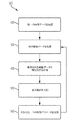
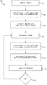
いくつかの実施形態では、正中線偏位モニタリングは、患者が低磁場MRI装置内に位置されたままである間に:(1)患者の脳の一部についての第一の磁気共鳴(MR)画像データを取得し;(2)前記第一のMRデータを入力として、トレーニングされた統計的分類器(たとえば畳み込みニューラルネットワーク)に提供して、対応する第一の出力を得て;(3)前記第一の出力から、患者の脳の少なくとも一つの正中線構造に関連する少なくとも一つの目印の少なくとも一つの初期位置を識別し;(4)前記第一のMR画像データを取得した後に(たとえば一時間以内に)患者の脳の前記部分についての第二のMR画像データを取得し;(5)前記第二のMR画像データを入力として、前記トレーニングされた統計的分類器に提供して、対応する第二の出力を得て;(6)前記第二の出力から、患者の脳の前記少なくとも一つの正中線構造に関連する前記少なくとも一つの目印の少なくとも一つの更新された位置を識別し;(7)前記少なくとも一つの目印の前記少なくとも一つの初期位置と前記少なくとも一つの目印の前記少なくとも一つの更新された位置とを使って前記正中線偏位における変化の度合いを決定することに関わる。 In some embodiments, midline excursion monitoring is performed while the patient remains positioned in the low field MRI apparatus: (1) a first magnetic resonance (MR) image of a portion of the patient's brain. (2) providing said first MR data as input to a trained statistical classifier (eg, a convolutional neural network) to obtain a corresponding first output; (3) said Identifying from the first output at least one initial location of at least one landmark associated with at least one midline structure of the patient's brain; (4) after acquiring the first MR image data (eg, one (Within time) obtaining second MR image data for the part of the patient's brain; (5) providing the second MR image data as input to the trained statistical classifier Second out to (6) identifying, from the second output, at least one updated location of the at least one landmark associated with the at least one midline structure of the patient's brain; Using the at least one initial position of at least one landmark and the at least one updated position of the at least one landmark to determine a degree of change in the midline deviation.
いくつかの実施形態では、患者の脳の前記少なくとも一つの正中線構造に関連付けられた前記少なくとも一つの目印は、大脳鎌の(患者の当該の内板への)前付着点(anterior attachment point)、大脳鎌の後付着点、透明中隔上の点を含んでいてもよい。他の実施形態では、前記少なくとも一つの目印は、脳の左右の側および/または脳の上下の部分のセグメント分割の結果を示していてもよい。 In some embodiments, the at least one landmark associated with the at least one midline structure of the patient's brain is an anterior attachment point (to the patient's relevant inner plate) of the cerebral sickle. , Posterior attachment point of cerebral sickle, point on transparent septum may be included. In another embodiment, the at least one landmark may indicate the result of segmentation of the left and right sides of the brain and / or the upper and lower portions of the brain.
いくつかの実施形態では、前記トレーニングされた統計的分類器の前記第一の出力から患者の脳の少なくとも一つの正中線構造に関連する少なくとも一つの目印の少なくとも一つの初期位置を識別することは:(1)大脳鎌の前付着点の初期位置を識別すること;(2)大脳鎌の後付着点の初期位置を識別すること;および(3)透明中隔上の測定点の初期位置を識別することを含む。前記トレーニングされた統計的分類器の前記第二の出力から、患者の脳の前記少なくとも一つの正中線構造に関連する前記少なくとも一つの目印の少なくとも一つの更新された位置を識別することは:(1)大脳鎌の前付着点の更新された位置を識別すること;(2)大脳鎌の後付着点の更新された位置を識別すること;および(3)透明中隔上の測定点の更新された位置を識別することを含む。すると、正中線偏位の変化の度合いは、大脳鎌の前付着点、大脳鎌の後付着点および透明中隔上の測定点の識別された初期位置および更新された位置を使って実行されうる。 In some embodiments, identifying from the first output of the trained statistical classifier at least one initial position of at least one landmark associated with at least one midline structure of the patient's brain is : (1) identifying the initial position of the pre-adhesion point of the cerebrum sickle; (2) identifying the initial position of the cerebrum sickle attachment point; and (3) identifying the initial position of the measurement point on the transparent septum Including identifying. Identifying from the second output of the trained statistical classifier at least one updated location of the at least one landmark associated with the at least one midline structure of the patient's brain is: 1) identifying the updated position of the cerebral sickle's pre-attachment point; (2) identifying the updated position of the posterior attachment point of the cerebral sickle; and (3) updating the measurement point on the transparent septum. Identifying identified locations. The degree of change in the midline deviation can then be performed using the identified initial and updated positions of the pre-attachment point of the cerebrum, the posterior attachment point of the cerebrum and the measurement points on the transparent septum .
いくつかの実施形態では、前記正中線偏位における変化の度合いを決定することは、大脳鎌の前付着点、大脳鎌の後付着点および透明中隔上の測定点の識別された初期位置を使って正中線偏位の初期量を決定し;大脳鎌の前付着点、大脳鎌の後付着点および透明中隔上の測定点の識別された更新された位置を使って正中線偏位の更新された量を決定し;正中線偏位の初期量および更新された量を使って正中線偏位における変化の度合いを決定することを含む。 In some embodiments, determining the degree of change in the midline excursion comprises identifying the initial position of the cerebral sickle front attachment point, the cerebral sickle rear attachment point, and the measurement point on the transparent septum. To determine the initial amount of midline deviation; using the identified updated positions of the cerebral sickle front attachment point, cerebral sickle rear attachment point and measurement points on the transparent septum, Determining an updated amount; using the initial amount of the midline deviation and the updated amount to determine the degree of change in the midline deviation.
いくつかの実施形態では、前記トレーニングされた統計的分類器は、多層ニューラルネットワークであってもよい。たとえば、多層ニューラルネットワークは、畳み込みニューラルネットワーク(たとえば畳み込み層、プーリング層および全結合層をもつもの)または全層畳み込みニューラルネットワーク(たとえば全結合層のない畳み込みニューラルネットワーク)であってもよい。もう一つの例として、多層ニューラルネットワークは、畳み込みおよびリカレント(たとえば長短期記憶)ニューラルネットワークであってもよい。 In some embodiments, the trained statistical classifier may be a multilayer neural network. For example, the multi-layer neural network may be a convolutional neural network (eg, having a convolutional layer, a pooling layer, and a fully connected layer) or an all-layer convolutional neural network (eg, a convolutional neural network without a fully connected layer). As another example, the multi-layer neural network may be a convolutional and recurrent (eg, long-term memory) neural network.
本発明者らは、患者の脳における異常(たとえば出血、障害、浮腫、卒中核、卒中周縁部および/または膨潤)のサイズに変化があるかどうかを判定するための低磁場MRI技法を開発した。いくつかの実施形態では、低磁場MRIモニタリング技法は、異常のサイズを連続的にモニタリングし、時間を追ってそのサイズの変化を検出するために、機械学習技法と組み合わされてもよい。そのような実施形態では、低磁場MRIモニタリングは、患者の脳の画像のシーケンスを取得することを許容し、該画像のシーケンスから、異常のサイズの対応するシーケンスを決定するために機械学習技法(たとえば畳み込みニューラルネットワークのような深層学習技法)が使用されうる。たとえば、本発明者らによって開発された深層学習技法は、MRI画像における異常をセグメント分割する、2Dまたは3Dバウンディング領域(たとえばボックス)の主軸を指定する点を識別する、異常の最大直径および該最大直径に直交する異常の最大直交直径を識別する、および/または異常のサイズを識別することを進めることにおける他の任意の処理を実行するために、使用されうる。 We have developed a low field MRI technique to determine if there is a change in the size of an abnormality (eg, bleeding, injury, edema, stroke nucleus, stroke margin and / or swelling) in the patient's brain. . In some embodiments, low field MRI monitoring techniques may be combined with machine learning techniques to continuously monitor the size of the anomaly and detect changes in that size over time. In such embodiments, low field MRI monitoring allows obtaining a sequence of images of the patient's brain, and from the sequence of images, machine learning techniques ( For example, deep learning techniques such as convolutional neural networks may be used. For example, the deep learning technique developed by the inventors identifies the maximum diameter of an anomaly and the maximum that identifies the point that specifies the principal axis of a 2D or 3D bounding region (eg, a box) that segments the anomaly in an MRI image. It can be used to identify the maximum orthogonal diameter of an anomaly that is orthogonal to the diameter and / or perform any other process in proceeding to identify the size of the anomaly.
よって、いくつかの実施形態では、異常サイズ・モニタリングは、患者が低磁場MRI装置内に位置されたままである間に:(1)患者の脳の一部についての第一の磁気共鳴(MR)画像データを取得し;(2)前記第一のMRデータを入力として、トレーニングされた統計的分類器(たとえば多層ニューラルネットワーク、畳み込みニューラルネットワーク、全層畳み込みニューラルネットワーク)に提供して、対応する第一の出力を得て;(3)前記第一の出力を使って、患者の脳における異常のサイズを示す少なくとも一つの特徴の少なくとも一つの初期値を識別し;(4)前記第一のMR画像データを取得した後に患者の脳の前記部分についての第二のMR画像データを取得し;(5)前記第二のMR画像データを入力として、前記トレーニングされた統計的分類器に提供して、対応する第二の出力を得て;(5)前記第二の出力から、患者の脳における異常のサイズを示す前記少なくとも一つの特徴の少なくとも一つの更新された値を識別し;(6)前記少なくとも一つの特徴の前記少なくとも一つの初期値と前記少なくとも一つの特徴の前記少なくとも一つの更新された値とを使って前記異常のサイズにおける変化を決定することに関わる。 Thus, in some embodiments, abnormal size monitoring is performed while the patient remains positioned in the low field MRI apparatus: (1) First magnetic resonance (MR) for a portion of the patient's brain Obtaining image data; (2) providing the first MR data as input to a trained statistical classifier (eg, multilayer neural network, convolutional neural network, full-layer convolutional neural network) and corresponding first (3) using the first output to identify at least one initial value of at least one feature indicative of the size of the abnormality in the patient's brain; (4) the first MR Acquiring second MR image data for the portion of the patient's brain after acquiring image data; (5) receiving the second MR image data as input and training Providing to a statistical classifier to obtain a corresponding second output; (5) from the second output, updated at least one of the at least one feature indicative of the size of the abnormality in the patient's brain Identifying a value; (6) determining a change in the size of the anomaly using the at least one initial value of the at least one feature and the at least one updated value of the at least one feature. Involved.
いくつかの実施形態では、前記異常のサイズを示す前記少なくとも一つの特徴の前記少なくとも一つの初期値は、前記異常の周囲の領域を指定する複数の値(たとえば、バウンディング領域を指定する値、異常の周を指定する値など)を含んでいてもよい。いくつかの実施形態では、前記少なくとも一つの特徴の前記少なくとも一つの初期値は、異常の一つまたは複数の直径(たとえば図11Aに示されるような、直径1102および直径1102に直交する直径1104)を指定する値を含んでいてもよい。
In some embodiments, the at least one initial value of the at least one feature indicative of the size of the anomaly is a plurality of values that specify an area surrounding the anomaly (eg, a value that specifies a bounding area, an anomaly May be included). In some embodiments, the at least one initial value of the at least one feature is one or more diameters of anomalies (eg,
いくつかの実施形態では、前記異常のサイズにおける変化を決定することは:(1)前記少なくとも一つの特徴の前記少なくとも一つの値を使って異常の初期サイズを決定し;(2)前記少なくとも一つの特徴の前記少なくとも一つの更新された値を使って異常の更新されたサイズを決定し;(3)異常の決定された初期サイズおよび更新されたサイズを使って異常のサイズにおける変化を決定することに関わる。 In some embodiments, determining the change in the size of the anomaly: (1) determining the initial size of the anomaly using the at least one value of the at least one feature; Determining an updated size of the anomaly using the at least one updated value of one feature; (3) determining a change in the size of the anomaly using the determined initial size and the updated size of the anomaly Related to that.
下記は、低磁場MRIを含む低磁場磁気共鳴アプリケーションを使ってモニタリングを実行するための方法および装置に関係したさまざまな概念およびその実施形態の、より詳細な記述である。本稿に記載されるさまざまな側面が数多くの仕方の任意のもので実装されうることは理解しておくべきである。具体的実装の例は、単に例解目的で、本稿において与えられる。さらに、下記の実施形態において記述されるさまざまな側面は、単独でまたは任意の組み合わせにおいて使用されることができ、本稿に明示的に記載される組み合わせに限定されるものではない。 The following is a more detailed description of various concepts and embodiments related to methods and apparatus for performing monitoring using low field magnetic resonance applications including low field MRI. It should be understood that the various aspects described in this article can be implemented in any of a number of ways. Specific implementation examples are given in this paper for illustrative purposes only. Further, the various aspects described in the embodiments below can be used alone or in any combination and are not limited to the combinations explicitly described in this paper.
図1は、MRIシステム100の例示的コンポーネントのブロック図である。図1の例示的な例では、MRIシステム100は、ワークステーション104、コントローラ106、パルス・シーケンス記憶部108、電力管理システム110および磁気コンポーネント120を有する。システム100は例示的であり、MRIシステムが、図1に示したコンポーネントに加えてまたはその代わりに、任意の好適な型の一つまたは複数の他のコンポーネントを有していてもよいことを理解しておくべきである。
FIG. 1 is a block diagram of exemplary components of an
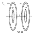
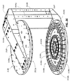
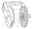
図1に示されるように、磁気コンポーネント120はB0磁石122、シム・コイル124、RF送信および受信コイル126および傾斜コイル128を有する。B0磁石122は、少なくとも部分的に主磁場B0を生成するために使用されうる。B0磁石122は、主磁場(たとえば約0.2T以下の低磁場強度)を生成できる任意の好適な型の磁石であってもよく、一つまたは複数のB0コイル、補正コイルなどを含んでいてもよい。シム・コイル124は、磁石122によって生成されるB0場の均一性を改善するための磁場(単数または複数)を寄与するために使用されてもよい。傾斜コイル128は、傾斜場を提供するよう構成されてもよく、どこでMR信号が誘起されるかを局在化するために、たとえば、三つの実質的に直交する方向(X,Y,Z)における磁場内の勾配を生成するよう構成されてもよい。
As shown in FIG. 1, the
RF送信および受信コイル126は、磁場B1を誘起するためのRFパルスを生成するために使われうる一つまたは複数の送信コイルを有していてもよい。該送信/受信コイル(単数または複数)は、被験体においてMR応答を励起するよう構成された任意の好適な型のRFパルスを生成し、結果として生じる、放出されるMR信号を検出するよう構成されてもよい。RF送信および受信コイル126は、一つまたは複数の送信コイルおよび一つまたは複数の受信コイルを含んでいてもよい。送信/受信コイルの構成は実装により変わり、送受信両方のための単一のコイル、送信および受信のための別個のコイル、送信および/または受信のための複数のコイルまたは単一チャネルもしくはパラレルMRIシステムを達成するための任意の組み合わせを含みうる。このように、送信/受信磁気コンポーネントは、MRIシステムの送信および受信コンポーネントのための上記さまざまな構成を一般に指して、しばしばTx/RxまたはTx/Rxコイルと称される。磁気系コンポーネント120のそれぞれは、いかなる好適な仕方で構築されてもよい。たとえば、いくつかの実施形態では、磁気系コンポーネント120の一つまたは複数は、上記で組み込まれた同時出願された出願に記載されるラミネート技法を使って製作されてもよい。
The RF transmit and receive
電力管理システム110は、低磁場MRIシステム100の一つまたは複数のコンポーネントに動作電力を提供するための電子回路を含む。たとえば、電力管理システム110は一つまたは複数の電源、傾斜電力増幅器、送信コイル増幅器および/または低磁場MRIシステム100のコンポーネントにエネルギーを与え動作させるために好適な動作電力を提供するために必要とされる他の任意の好適な電力電子回路を含みうる。
The
図1に示されるように、電力管理システム110は、電源112、増幅器114、送受切り換えスイッチ116および熱管理コンポーネント118を有する。電源112は、低磁場MRIシステム100の磁気コンポーネント120に動作電力を提供するための電子回路を含む。たとえば、電源112は一つまたは複数のB0コイル(たとえばB0磁石122)に、低磁場MRIシステムのための主磁場を生成するよう動作電力を提供するための電子回路を含んでいてもよい。いくつかの実施形態では、電源112は単極の連続波(CW)電源であってもよいが、いかなる好適な電源が使われてもよい。RF送信コイルまたはRF受信コイルのどちらが動作させられるかを選択するために送受切り換えスイッチ116が使われてもよい。
As shown in FIG. 1, the
増幅器(単数または複数)114は、一つまたは複数のRF受信コイル(たとえばコイル124)によって検出されるMR信号を増幅する一つまたは複数のRF受信(Rx)前置増幅器、一つまたは複数のRF送信コイル(たとえばコイル126)に電力を提供するよう構成された一つまたは複数のRF送信(Tx)増幅器、一つまたは複数の傾斜コイル(たとえば傾斜コイル128)に電力を提供するよう構成された一つまたは複数の傾斜電力増幅器および一つまたは複数のシム・コイル(たとえばシム・コイル124)に電力を提供するよう構成されたシム増幅器を含んでいてもよい。 The amplifier (s) 114 are one or more RF receive (Rx) preamplifiers, one or more amplifiers that amplify MR signals detected by one or more RF receive coils (eg, coil 124). One or more RF transmit (Tx) amplifiers configured to provide power to an RF transmit coil (eg, coil 126), configured to provide power to one or more gradient coils (eg, gradient coil 128) One or more gradient power amplifiers and a shim amplifier configured to provide power to one or more shim coils (eg, shim coil 124) may be included.
熱管理コンポーネント118は、低磁場MRIシステム100のコンポーネントのための冷却を提供し、低磁場MRIシステム100の一つまたは複数のコンポーネントによって生成される熱エネルギーをそれらのコンポーネントから運び去ることを容易にすることによって冷却を行なうよう構成されてもよい。熱管理コンポーネント118は、限定なしに、水冷式または空冷式冷却を実行するためのコンポーネントを含んでいてもよく、かかるコンポーネントは、B0コイル、傾斜コイル、シム・コイルおよび/または送信/受信コイルを含むがそれに限られない、熱を生じるMRIコンポーネントと統合されてもよく、あるいは近接して配置されてもよい。熱管理コンポーネント118は、低磁場MRIシステム100のコンポーネントから熱を運び去るための、空気および水を含むがそれに限られないいかなる好適な熱輸送媒体を含んでいてもよい。
The
図1に示されるように、低磁場MRIシステム100は、電力管理システム110に命令を送り、これから情報を受け取る制御電子回路を有するコントローラ106(コンソールとも称される)を含んでいる。コントローラ106は一つまたは複数のパルス・シーケンスを実装するよう構成されてもよい。パルス・シーケンスは、磁気コンポーネント120を所望されるシーケンスで動作させるために電力管理システム110に送られる命令を決定するために使われる。たとえば、コントローラ106は、均衡定常状態自由歳差(bSSFP: balance steady-state free precession)パルス・シーケンス、低磁場グラジエントエコー・パルス・シーケンス、低磁場スピンエコー・パルス・シーケンス、低磁場反転回復パルス・シーケンス、動脈スピン・ラベリング、拡散強調撮像(DWI: diffusion weighted imaging)パルス・シーケンスおよび/または他の任意の好適なパルス・シーケンスに従って磁気コンポーネント120を動作させるよう電力管理システム110を制御するよう構成されてもよい。コントローラ106は、ハードウェア、ソフトウェアまたはハードウェアとソフトウェアの任意の好適な組み合わせとして実装されうる。本稿で与えられる開示の側面はこれに関して限定されない。
As shown in FIG. 1, the low
いくつかの実施形態では、コントローラ106は、一つまたは複数のパルス・シーケンスのそれぞれについての情報を記憶しているパルス・シーケンス貯蔵部108からパルス・シーケンスについての情報を得ることによって、パルス・シーケンスを実装するよう構成されてもよい。特定のパルス・シーケンスについてパルス・シーケンス貯蔵部108に記憶されている情報は、コントローラ106がその特定のパルス・シーケンスを実装できるようにするいかなる好適な情報であってもよい。たとえば、パルス・シーケンスについてパルス・シーケンス貯蔵部108に記憶されている情報は、そのパルス・シーケンスに従って磁気系コンポーネント120を動作させるための一つまたは複数のパラメータ(たとえば、RF送信および受信コイル126を動作させるためのパラメータ、傾斜コイル128を動作させるためのパラメータなど)、そのパルス・シーケンスに従って電力管理システム110を動作させるための一つまたは複数のパラメータ、コントローラ106によって実行されたときにコントローラ106がシステム100を制御してそのパルス・シーケンスに従って動作するようにする命令を含む一つまたは複数のプログラムおよび/または他の任意の好適な情報を含んでいてもよい。パルス・シーケンス貯蔵部108に記憶されている情報は、一つまたは複数の非一時的な記憶媒体に記憶されていてもよい。
In some embodiments, the
図1に示されるように、コントローラ106は、受信されたMRデータを処理するようプログラムされたコンピューティング装置104とも対話する。たとえば、コンピューティング装置104は、任意の好適な画像再構成プロセスを使って、受信されたMRデータを処理して一つまたは複数のMR画像を生成してもよい。コントローラ106は、一つまたは複数のパルス・シーケンスについての情報を、コンピューティング装置によるデータの該処理のために、コンピューティング装置104に提供してもよい。たとえば、コントローラ106は、一つまたは複数のパルス・シーケンスについての情報をコンピューティング装置104に提供してもよく、コンピューティング装置は少なくとも部分的には該提供された情報に基づいて画像再構成プロセスを実行してもよい。
As shown in FIG. 1, the
コンピューティング装置104は、収集されたMRデータを処理して撮像される被験体の一つまたは複数の画像を生成しうるいかなる電子装置であってもよい。いくつかの実施形態では、コンピューティング装置104は、デスクトップ・コンピュータ、サーバー、ラックマウント・コンピュータまたは他の任意の好適な固定電子装置でMRデータを処理して撮像される被験体の一つまたは複数の画像を生成するよう構成されうるものといった固定電子装置であってもよい。あるいはまた、コンピューティング装置104は、スマートフォン、携帯情報端末、ラップトップ・コンピュータ、タブレット・コンピュータまたはMRデータを処理して撮像される被験体の一つまたは複数の画像を生成するよう構成されうる他の任意のポータブル装置といったポータブル装置であってもよい。いくつかの実施形態では、コンピューティング装置104は、いかなる好適な型の複数のコンピューティング装置を含んでいてもよい。諸側面はこれに関して限定されない。ユーザー102がワークステーション104と対話して、低磁場MRシステム100の諸側面を制御したり(たとえば、特定のパルス・シーケンスに従って動作するようシステム100をプログラムする、システム100の一つまたは複数のパラメータを調整する、など)、および/または低磁場MRシステム100によって得られた画像を閲覧したりしてもよい。いくつかの実施形態によれば、コンピューティング装置104およびコントローラ106は単一のコントローラをなしてもよく、他の実施形態では、コンピューティング装置104およびコントローラ106はそれぞれ一つまたは複数のコントローラを有する。コンピューティング装置104およびコントローラ106によって実行される機能が、一つまたは複数のコントローラの任意の組み合わせに任意の仕方で分配されうることを理解しておくべきである。諸側面はいかなる特定の実装やアーキテクチャーにも限定されない。
The
図2Aおよび2Bは、本稿に記載される変化検出技法と一緒に使うのに好適な低磁場MRIシステムにおいて使用されうる二平面磁気構成を示している。図2Aは、低磁場MRIのために好適なB0磁場の一部を少なくとも部分的に生成するよう構成された二平面磁石を概略的に示している。二平面磁石200は、二つの外側コイル210aおよび210bならびに二つの内側コイル212aおよび212bを有する。これらのコイルに適切な電流が加えられるとき、矢印によって示される方向に磁場が生成されて、コイルの間に視野をもつB0場を生成する。これは、適切に設計され構築されれば、低磁場MRIのために好適でありうる。用語「コイル」は本稿では、磁場を生成するための電流を伝える少なくとも一つの「ターン」をもち、それにより電磁石を形成する任意の幾何構成の任意の導体または導体の組み合わせを指す。
2A and 2B illustrate a two-plane magnetic configuration that can be used in a low field MRI system suitable for use with the change detection technique described herein. FIG. 2A schematically illustrates a biplanar magnet configured to at least partially generate a portion of the B 0 field suitable for low field MRI. The
図2Aに示される二平面幾何が一般に、高い磁場強度で十分な均一性のB0磁場を得ることの困難のため、高磁場MRIについては不適であることを理解しておくべきである。高磁場MRIシステムは、高磁場MRIのための十分な均一性の高磁場強度を達成するために、典型的にはソレノイド幾何(および超伝導ワイヤ)を利用する。図2Aに示される二平面B0磁石は概して開放的な幾何構成を提供し、閉所恐怖症を患い通常の高磁場ソレノイド・コイル幾何で撮像されることを拒むことがある患者と一緒に使うことを容易にする。さらに、二平面設計は、その開放的な設計および場合によっては低磁場強度および均一性要件で可能な概してより大きな視野の結果として、より大きな患者と一緒に使うことを容易にしうる。さらに、概して開放的な設計は、撮像される患者へのアクセスを容易にし、患者、たとえば意識のない、鎮静されたまたは麻酔された患者を視野内に位置決めする能力を改善しうる。これについてはのちにより詳細に論じる。図2Aにおける二平面幾何は単に例であり、必要に応じてより多数またはより少数のコイルが配置されてもよい。諸側面はこの点で限定されない。 It should be understood that the biplanar geometry shown in FIG. 2A is generally unsuitable for high field MRI due to the difficulty in obtaining a sufficiently uniform B 0 field at high field strength. High field MRI systems typically utilize solenoid geometry (and superconducting wires) to achieve high field strength with sufficient uniformity for high field MRI. The two-plane B0 magnet shown in FIG. 2A provides a generally open geometry, for use with patients who suffer claustrophobia and may refuse to be imaged with the usual high field solenoid coil geometry To make it easier. Furthermore, the biplanar design may facilitate use with larger patients as a result of its open design and possibly a larger field of view possible with low field strength and uniformity requirements. Further, the generally open design may facilitate access to the patient being imaged and may improve the ability to position a patient, eg, an unconscious, sedated or anesthetized patient, within the field of view. This will be discussed in more detail later. The biplanar geometry in FIG. 2A is merely an example, and more or fewer coils may be placed as needed. Aspects are not limited in this respect.
図2Bは、B0磁石またはその一部を製作するおよび/または低磁場MRIにおいて使うための一つまたは複数の他の磁気コンポーネントを製作するためにラミネート技法を使うハイブリッド二平面磁石を示している。たとえば、図2Bに示される例示的な二平面磁石200’において、ラミネート・パネル220aおよび220bが内側コイル212aおよび212bを置換して、ハイブリッド磁石を生成する。ラミネート・パネル220aおよび220bは任意の数のラミネート層を含んでいてもよく、ラミネート層の上には、低磁場MRIにおいて使われる磁場の生成を容易にするための一つまたは複数のB0コイル、傾斜コイル、補正コイルおよび/またはシム・コイルなどまたはその一部が製作されている。ラミネート技法を使う好適なハイブリッド磁石は、ここに参照によってその全体において組み込まれる2015年9月4日に出願された、「低磁場磁気共鳴撮像方法および装置」と題する米国特許出願第14/845652号('652出願)に記載されている。他の実施形態では、ラミネート技法は、B0磁石をその全体において実装する(たとえばコイル210aおよび210bを置換する)ために使用されることができる。
2B shows a hybrid two planes magnet using a laminate technique to fabricate one or more other magnetic components for use in the B 0 magnetic or and / or low field MRI fabricating a portion thereof . For example, in the
例示的なラミネート・パネル220aおよび220bの上には、追加的または代替的に、受信されるMR信号の空間位置を周波数または位相の関数としてエンコードするための一つまたは複数のコイルまたはその一部が製作されていてもよい。いくつかの実施形態によれば、ラミネート・パネルは、低磁場MRIシステムにおいて動作させられるときに検出されたMR信号の空間エンコードを提供するのに好適な磁場を生成するまたは該磁場に寄与することのできる一つまたは複数の傾斜コイルまたは一つまたは複数の傾斜コイルの一部を形成するようパターン化された少なくとも一つの伝導層を有する。たとえば、ラミネート・パネル220aおよび/またはラミネート・パネル220bは、第一(X)方向においてB0場を選択的に変化させてその方向における周波数エンコードを実行するよう構成された第一の傾斜コイル、第一方向と実質的に直交する第二(Y)方向においてB0場を選択的に変化させて位相エンコードを実行するよう構成された第二の傾斜コイル、および/または第一方向および第二方向と実質的に直交する第三(Z)方向においてB0場を選択的に変化させて体積撮像アプリケーションのためのスライス選択を可能にするよう構成された第三の傾斜コイルを有していてもよい。
Above the
例示的なラミネート・パネル220aおよび220bは、追加的または代替的に、追加的な磁気コンポーネントを含んでいてもよい。追加的な磁気コンポーネントは、たとえばB0場の強度を増すおよび/または均一性を改善する、傾斜コイルの動作、撮像されるオブジェクトの負荷効果によって生成されるような有害な場の効果に対抗するまたは他の仕方で低磁場MRIシステムの磁気系を支援するためにシステムを支援する磁場を生成するよう構成された一つまたは複数のシム・コイルなどである。図2Aおよび2Bに示される二平面磁石は、通常のコイル、ラミネート技法または両者の組み合わせを使って生産されてもよく、変化検出技法を実行するよう適応された低磁場MRIシステムのための磁気コンポーネントを提供するために使われてもよい。これについてはのちにより詳細に論じる。
本発明者らは、低磁場コンテキストが、高磁場領域では実現可能でなかったB0磁石設計を許容することを認識するに至った。たとえば少なくとも部分的には、より低い磁場強度のため、超伝導材料および対応する低温冷却システムをなくすことができる。部分的には低磁場強度のため、非超伝導材料(たとえば銅)を使って構築されたB0電磁石が低磁場領域では用いられてもよい。しかしながら、そのような電磁石はそれでも動作中、比較的大量の電力を消費することがありうる。たとえば、銅導体を使った電磁石を動作させて0.2T以上の磁場を生成することは、専用のまたは特化した電力接続(たとえば専用の三相電力接続)を必要とする。本発明者らは、幹線電気(すなわち標準的な壁のコンセントの電力)を使って動作させることのできるMRIシステムを開発した。それは、MRIシステムが標準的な壁のコンセント(たとえば米国では120V/20A接続)または一般的な大型機器用コンセント(たとえば220〜240V/30A)のような一般的な電力接続をもつ任意の位置で電力を与えられることを許容する。こうして、低電力MRIシステムは、ポータブル性および利用可能性を容易にし、MRIシステムが必要とされる位置で動作されることを許容する(たとえば、患者がMRIシステムのところに連れてこられるのではなく、MRIシステムが患者のところにもってこられることができる)。その例は下記でさらに詳細に論じる。さらに、標準的な壁の電力から動作することは、三相電力を単相電力に変換し、グリッドから直接提供される電力を平滑化するために従来必要とされていた電子回路をなくす。その代わり、壁のコンセントの電力は直接DCに変換されて、MRIシステムのコンポーネントに電力を与えるために分配される。 The present inventors have found that low field context, in the high magnetic field region came to recognize that permit B 0 magnet design was not feasible. For example, at least in part, because of the lower magnetic field strength, superconducting materials and corresponding cryogenic cooling systems can be eliminated. In part because of the low magnetic field strength, B 0 electromagnets constructed using non-superconducting materials (eg, copper) may be used in the low magnetic field region. However, such electromagnets can still consume a relatively large amount of power during operation. For example, operating an electromagnet using copper conductors to generate a magnetic field of 0.2 T or more requires a dedicated or specialized power connection (eg, a dedicated three-phase power connection). The inventors have developed an MRI system that can be operated using mains electricity (ie, standard wall outlet power). It can be used in any location where the MRI system has a common power connection such as a standard wall outlet (eg 120V / 20A connection in the US) or a common large equipment outlet (eg 220-240V / 30A). Allow to be given power. Thus, a low-power MRI system facilitates portability and availability and allows the MRI system to be operated where it is needed (for example, instead of bringing the patient to the MRI system) MRI system can be brought to the patient). Examples are discussed in more detail below. Furthermore, operating from standard wall power eliminates the electronic circuitry previously required to convert three-phase power to single-phase power and smooth the power provided directly from the grid. Instead, the wall outlet power is directly converted to DC and distributed to power the components of the MRI system.
図2Cおよび2Dは、電磁石および強磁性ヨークを使って形成されるB0磁石を示している。具体的には、B0磁石2000は部分的には、上側の電磁コイル2012aおよび2012bおよびB0磁石2000の下側の電磁コイル2014aおよび2014bを有する、二平面幾何に配置された電磁石2010によって形成される。いくつかの実施形態によれば、電磁石2010を形成するコイルは、銅ワイヤまたは銅リボンまたは動作されるとき(たとえば導体巻き線を通じて電流が駆動されるとき)に磁場を生成するために好適な他の任意の伝導材料のいくつかのターンから形成されてもよい。図2Cおよび2Dに示される例示的な電磁石は二対のコイルを有するものの、電磁石は、任意の配位の任意の数のコイルを使って形成されうる。諸側面はこの点で限定されない。電磁石2010を形成する電磁コイルはたとえば、ファイバーグラス・リング2017のまわりに導体2013(たとえば銅リボン、ワイヤ、ペイントなど)を巻くことによって形成されてもよい。たとえば、導体2013は好適な絶縁された銅ワイヤであってもよく、あるいは代替的に、導体2013はコイルの複数の巻きを電気的に絶縁するための絶縁層(たとえばマイラー層)と一緒に巻かれた銅リボンであってもよい。コイル2014aおよび2014bを直列に動作させるための電流を提供する電力接続を許容するよう、コネクタ2019が設けられてもよい。電磁石の上側の同様のコネクタ(図2Cおよび2Dでは見えない)がコイル2012aおよび2012bを動作させるために設けられてもよい。
2C and 2D show the B 0 magnet formed with an electromagnet and a ferromagnetic yoke. Specifically, the B 0 magnet 2000 is formed in part by
所望されるB0磁場を生成するまたは所望されるB0磁場に寄与するよう、電磁コイルはいかなる好適な材料から形成されてもよく、いかなる好適な寸法にされてもよいことを理解しておくべきである。諸側面はいかなる特定の型の電磁石と一緒に使うためにも限定されない。部分的に電磁石(たとえば電磁石2010)を形成するのに好適でありうる一つの限定しない例として、電磁コイルは、銅リボンおよびマイラー絶縁体を使って構築されて、155ターンで約23〜27インチ(たとえば約25インチ)の内側直径、約30〜35インチ(たとえば約32インチ)の外側直径をなしてもよい。しかしながら、所望される特性をもつ電磁コイルを構築するために異なる材料および/または異なる寸法が使われてもよい。諸側面はこの点で限定されない。上下のコイル(単数または複数)は、上側にある下部コイルと下側にある上部コイルとの間の約10〜15インチ(たとえば約12.5インチ)の距離を与えるよう位置決めされてもよい。たとえば磁場強度、視野などを含む所望される特性に依存して寸法は変わってくることを理解しておくべきである。 Desired B 0 generates a magnetic field or contribute so the desired B 0 magnetic field, understand that the electromagnetic coil may be formed from any suitable material, it may be any suitable size Should. Aspects are not limited for use with any particular type of electromagnet. As one non-limiting example that may be suitable for partially forming an electromagnet (e.g., electromagnet 2010), the electromagnetic coil is constructed using copper ribbon and Mylar insulation to provide about 23-27 inches in 155 turns. An inner diameter (eg, about 25 inches) and an outer diameter of about 30-35 inches (eg, about 32 inches) may be made. However, different materials and / or different dimensions may be used to construct an electromagnetic coil with the desired properties. Aspects are not limited in this respect. The upper and lower coil (s) may be positioned to provide a distance of about 10-15 inches (e.g., about 12.5 inches) between the upper lower coil and the lower upper coil. It should be understood that the dimensions will vary depending on the desired properties including, for example, magnetic field strength, field of view, and the like.
図2Cおよび2Dに示される例示的なB0磁石では、各コイル対2012および2014は、それぞれ熱管理コンポーネント2030aおよび2030bによって分離されている。電磁コイルおよび傾斜コイル(図2Cおよび2Dには示さず)によって生成される熱を磁石から運び去り、MRI装置のための熱管理を提供するためである。具体的には、熱管理コンポーネント2030aおよび2030bは、磁石から熱を運び去るよう冷却プレートを通じて冷媒が循環されることを許容する導路をもつ冷却プレートであってもよい。冷却プレート2030a、2030bは、B0磁石2000によって生成されるB0磁場を乱す電磁場を生成できる、傾斜コイルを動作させることによって誘起される渦電流を減らすまたはなくすよう構築されうる。たとえば、熱管理コンポーネント2030aおよび2030bは、2015年9月4日に出願された、「熱管理方法および装置」と題する米国出願第14/846,042号に記載される熱管理コンポーネントのいずれかと同じまたは同様であってもよい。同出願は参照によってここにその全体において組み込まれる。いくつかの実施形態によれば、下記でさらに詳細に論じるように、熱管理コンポーネントはなくされてもよい。
In an exemplary B 0 magnet shown in FIGS. 2C and 2D, each coil pair 2012 and 2014 are separated from each other by the
B0磁石2000はさらに、電磁石に磁気的に結合されたヨーク2020を有する。ヨーク2020は、ヨーク2020がなければ失われてしまって上下の電磁コイルの間の関心領域における磁束密度に寄与しないであろう磁束を捕捉する。具体的には、ヨーク2020は、電磁石の上下の側のコイルをつなぐ「磁気回路」を形成して、コイル間の領域における磁束密度を増し、こうしてB0磁石の撮像領域(視野とも称される)内の磁場強度を増す。撮像領域または視野は、所与のB0磁石によって生成されるB0磁場が撮像のために好適である体積を定義する。より具体的には、撮像領域または視野は、B0磁場が所望される磁場強度で十分均一であり、高周波励起(たとえば好適な高周波パルス・シーケンス)の印加に応答してその中に位置されたオブジェクトによって、検出可能なMR信号が放出される領域に対応する。ヨーク2020は、フレーム2022およびプレート2024a、2024bを有し、これらはいかなる好適な強磁性材料(たとえば鉄、鋼など)を使って形成されてもよい。プレート2024a、2024bは、電磁石2010のコイル対によって生成された磁束を集め、それをフレーム2022に向ける。フレーム2022は磁束を反対側のコイル対に返し、それにより、コイルに与えられる同じ大きさの動作電流について、コイル対(たとえばコイル対2012a、2012bとコイル対2014a、2014b)の間の撮像領域における磁束密度を多ければ二倍まで増す。こうして、ヨーク2020は、電力要求の対応する増大なしに、より高いB0磁場(より高いSNRにつながる)を生成するために使用されることができ、あるいはヨーク2020は、所与のB0磁場についてB0磁石2000の電力要求を下げるために使われることができる。
The B0
いくつかの実施形態によれば、ヨーク2020の諸部分(すなわちフレーム2022および/またはプレート2024a、2024b)のために使われる材料は、鋼、たとえば低炭素鋼、ケイ素鋼、コバルト鋼などである。いくつかの実施形態によれば、MRIシステムの傾斜コイル(図2C、2Dには示さず)はプレート2024a、2024bに比較的近接して配置され、プレートに渦電流を誘起する。緩和するために、プレート2024a、2024bおよび/またはフレーム2022は、ケイ素鋼で構築されてもよい。ケイ素鋼は一般に、たとえば低炭素鋼よりも、渦電流生成に対して、より耐性がある。ヨーク2020が、十分な透磁率をもついかなる強磁性材料を使って構築されてもよく、個々の部分(たとえばフレーム2022およびプレート2024a、2024b)は同じまたは異なる強磁性材料で構築されてもよいことを理解しておくべきである。磁束密度を増す技法は、いかなる特定の型の材料または材料の組み合わせと一緒に使うためにも限定されない。さらに、ヨーク2020は、異なる幾何および配置を使って形成されることができることを理解しておくべきである。
According to some embodiments, the material used for portions of yoke 2020 (ie,
ヨーク2020がいかなる好適な材料でできていてもよく、重量、コスト、磁気的属性などといった他の設計上の制約条件を満たしつつ所望される磁束密度捕捉を提供するような寸法にされてもよいことを理解しておくべきである。例として、ヨークのフレーム(たとえばフレーム2022)は、炭素が0.2%未満の低炭素鋼またはケイ素鋼で形成されてもよく、長い梁(単数または複数)は約38インチの長さ、約8インチの幅および約2インチの厚さ(深さ)を有していてもよく、短い梁(単数または複数)は約19インチの長さ、約8インチの幅および約2インチの厚さ(深さ)を有していてもよい。プレート(たとえばプレート2024aおよび2024b)は、炭素が0.2%未満の低炭素鋼またはケイ素鋼で形成されてもよく、約30〜35インチ(たとえば約32インチ)の直径を有していてもよい。しかしながら、上記で与えた寸法および材料は単に、電磁石によって生成される磁束を捕捉するために使用できるヨークの好適な実施形態の例である。
The
ヨーク2020の使用により達成される改善の例として、ヨーク2020なしで約20mTのB0磁場を生成するために電磁石2010を動作させることは、約5kWを消費する一方、ヨーク2020を用いて同じ20mTのB0磁場を生成することは約750Wの電力を消費する。ヨーク2020を用いて電磁石2010を動作させれば、約40mTのB0磁場が2kWの電力を使って生成でき、約50mTのB0磁場が約3kWの電力を使って生成できる。このように、ヨーク220の使用により電力要求が著しく低減されることができ、専用の三相電力接続なしにB0磁石の動作を許容する。たとえば、米国および北米の大半における幹線電力は120Vおよび60Hzで提供され、15または20アンペアの定格であり、それぞれ1800および2400Wより下で動作する装置のための利用を許す。多くの施設は30アンペアの定格で220〜240VACのコンセントをももち、7200Wまでで動作する装置がそのようなコンセントから電力を受けることを許す。いくつかの実施形態によれば、電磁石およびヨークを有するB0磁石(たとえばB0磁石2000)を利用する低磁場MRIシステムは、下記でさらに詳細に論じるように、標準的な壁のコンセントを介して電力を受けるよう構成される。いくつかの実施形態によれば、電磁石およびヨークを有するB0磁石(たとえばB0磁石2000)を利用する低磁場MRIシステムは、やはり下記でさらに詳細に論じるように、220〜240VACコンセントを介して電力を受けるよう構成される。
As an example of the improvement achieved by using the
再び図2Cおよび2Dを参照するに、B0磁石2010はさらに、視野における(たとえばB0磁場が十分なMR信号生成のために好適である、電磁石の上下のコイルの間の領域における)均一性を改善するよう、生成されるB0磁場を増強するよう構成されたシム・リング2040a、2040bおよびシム・ディスク2042a、2042bを有する。これらは図2Dで最もよく見える。同図では下側のコイルは除去されている。具体的には、シム・リング2040およびシム・ディスク2042は、少なくともB0磁石の視野内で電磁石によって生成される磁場の一様性を増すような寸法および配置にされている。具体的には、シム・リング2040a、2040bの高さ、厚さおよび材料ならびにシム・ディスク2042a、2042bの直径、厚さおよび材料は、好適な均一性のB0磁場を達成するよう選択されうる。たとえば、シム・ディスクは約5〜6インチの直径および約0.3〜0.4インチの幅を与えられてもよい。シム・リングは、それぞれ約20〜22インチの高さおよび約2インチの幅をもつ複数の円弧セグメント(たとえば8個の円弧セグメント)から形成されて、約21〜22インチの間および約23〜24インチの間の内側直径をそれぞれ有するリングを形成してもよい。
Referring to FIG. 2C and 2D again, B 0 magnet 2010 Further, in the field of view (e.g. B 0 magnetic field is suitable for sufficient MR signal generation, in the region between the upper and lower coil of the electromagnet) uniformity To improve the generated B 0 field to have shim rings 2040a, 2040b and shim disks 2042a, 2042b. These are best seen in FIG. 2D. In the figure, the lower coil is removed. Specifically, shim rings 2040 and
B0磁石の重量は、MRIシステムの全体的な重量のかなりの部分であり、これがMRIシステムのポータブル性に影響する。ヨークおよびシミング・コンポーネントのために低炭素および/またはケイ素鋼を主として使う実施形態では、上記と同様の寸法にされた例示的なB0磁石2000は約550キログラムの重量であることがある。いくつかの実施形態によれば、コバルト鋼(CoFe)がヨーク(および可能性としてはシム・コンポーネント)のための主要な材料として使われてもよく、B0磁石2000の重量を約450キログラムにまで減らす可能性がある。しかしながら、CoFeは一般に、たとえば低炭素鋼よりも高価であり、システムのコストを押し上げる。よって、いくつかの実施形態では、CoFeの使用から生じるコストと重量との間のトレードオフを均衡させるため、選ばれたコンポーネントがCoFeを使って形成されてもよい。そのような例示的なB0磁石を使って、ポータブル、カート移動可能または他の仕方で搬送可能なMRIシステムが構築されうる。これは、たとえば、MRIシステムが所望される位置に搬送されること(これはMRIシステムを手で押すことおよび/または電動化された支援を含めることによる)を許容するよう、B0磁石を、キャスター、車輪または他の移動手段が取り付けられることのできる筐体、フレームまたは他のボディー内に統合することによる。結果として、MRIシステムは、必要とされる位置にもってこられることができ、臨床機器としてその利用可能性および使用を増し、以前には可能でなかったMRI用途を利用可能にする。 Weight of B 0 magnet is an overall significant portion of the weight of the MRI system, which will affect the portability of the MRI system. In mainly using embodiments the low carbon and / or silicon steel for the yoke and shimming components, it may be the exemplary B 0 magnet 2000 which is the same size and the weight of about 550 kilograms. According to some embodiments, (as and possibly shim component) cobalt steel (CoFe) is yoke may be used as the main material for the weight of the B 0 magnetic 2000 to about 450 kg There is a possibility to reduce up to. However, CoFe is generally more expensive than, for example, low carbon steel, which increases the cost of the system. Thus, in some embodiments, selected components may be formed using CoFe to balance the trade-off between cost and weight resulting from the use of CoFe. Using such exemplary B 0 magnet, portable, MRI systems can be conveyed in the cart moveable or otherwise can be constructed. This, for example, allows the B 0 magnet to be transported to the desired location (this is by manually pushing the MRI system and / or including motorized assistance), By integrating into a housing, frame or other body to which casters, wheels or other moving means can be attached. As a result, the MRI system can be brought to the required location, increasing its availability and use as a clinical instrument, making available MRI applications that were not previously possible.
B0磁石2000のようなB0磁石を用いる低磁場MRIシステムの全体的な電力消費に対する主要な寄与要因は、電磁石(たとえば電磁石2010)である。たとえば、いくつかの実施形態では、電磁石は全体的なMRIシステムの電力の80%以上を消費することがある。MRIシステムの電力要件を有意に下げるために、本発明者らは、B0電磁場を生成するおよび/またはB0電磁場に寄与するために永久磁石を利用するB0磁石を開発した。いくつかの実施形態によれば、B0電磁石は、B0電磁場の主要な源として永久磁石で置き換えられる。永久磁石とは、ひとたび磁化されたら自分自身の恒久的な磁場を維持する任意の物体または物質をいう。磁化されて永久磁石を作り出すことのできる物質は本稿では強磁性と称され、限定しない例として、鉄、ニッケル、コバルト、ネオジム(NdFeB)合金、サマリウムコバルト(SmCo)合金、アルニコ(AlNiCo)合金、ストロンチウムフェライト、バリウムフェライトなどを含む。永久磁石材料(たとえば磁化する場によって飽和に駆動された磁化可能な材料)は、駆動場が除去されるときにその磁場を保持する。特定の材料によって保持される磁化の量はその物質の残留磁気と称される。このように、ひとたび磁化されたら、永久磁石はその残留磁気に対応する磁場を生成し、磁場を生成するための電源の必要性をなくす。 A major contributor to the overall power consumption of low field MRI systems that use B 0 magnets, such as B 0 magnet 2000, is the electromagnet (eg, electromagnet 2010). For example, in some embodiments, the electromagnet may consume 80% or more of the overall MRI system power. To reduce the power requirements of the MRI system significantly, the present inventors have developed a B 0 magnet utilizing a permanent magnet in order to contribute to and / or B 0 field for generating a B 0 field. According to some embodiments, the B 0 electromagnet is replaced with a permanent magnet as the primary source of the B 0 electromagnetic field. A permanent magnet refers to any object or substance that maintains its own permanent magnetic field once magnetized. Materials that can be magnetized to create permanent magnets are referred to as ferromagnetism in this article and include, but are not limited to, iron, nickel, cobalt, neodymium (NdFeB) alloys, samarium cobalt (SmCo) alloys, alnico (AlNiCo) alloys, Including strontium ferrite and barium ferrite. Permanent magnet material (eg, a magnetizable material driven to saturation by a magnetizing field) retains its magnetic field when the driving field is removed. The amount of magnetization retained by a particular material is called the remanence of that material. Thus, once magnetized, the permanent magnet generates a magnetic field corresponding to its residual magnetism, eliminating the need for a power source to generate the magnetic field.
図2Eは、いくつかの実施形態に基づく永久B0磁石を示している。特に、B0磁石2100は、二平面幾何に配置された永久磁石2110aおよび2110bと、永久磁石によって生成される電磁束を捕捉してその磁束を反対側の永久磁石に伝達して、永久磁石2110aと2110bの間の磁束密度を増すヨーク2120とによって形成される。永久磁石2110aおよび2110bのそれぞれは複数の同心永久磁石から形成される。具体的には、図2Eに見て取れるように、永久磁石2110bは複数の永久磁石2114aの外側リング、複数の永久磁石2114bの中間リング、複数の永久磁石2114cの内側リングおよび中心の永久磁石ディスク2114dを有する。永久磁石2110aは、永久磁石2110bと同じ一組の永久磁石要素を有していてもよい。
FIG. 2E illustrates a permanent B0 magnet according to some embodiments. In particular, the B 0 magnet 2100 captures the electromagnetic flux generated by the
使用される永久磁石材料は、システムの設計要件に依存して選択されうる。たとえば、いくつかの実施形態によれば、永久磁石(またはその一部)は、ひとたび磁化されたら単位体積の材料当たり比較的高い磁場をもつ磁場を生成するNdFeBでできていてもよい。いくつかの実施形態によれば、永久磁石またはその一部を形成するためにSmCoが使われる。NdFeBのほうが高い磁場強度を生じる(かつ一般にはSmCoより安価である)が、SmCoのほうが熱ドリフトが少なく、よって温度ゆらぎがあるときに、より安定な磁場を提供する。他の型の永久磁石材料(単数または複数)が使われてもよい。諸側面はこの点で限定されない。一般に、利用される永久磁石材料の型(単数または複数)は少なくとも部分的には、所与のB0磁石実装の磁場強度、温度安定性、重量、コストおよび/または使いやすさの要件に依存する。 The permanent magnet material used can be selected depending on the design requirements of the system. For example, according to some embodiments, a permanent magnet (or a portion thereof) may be made of NdFeB that, once magnetized, generates a magnetic field with a relatively high magnetic field per unit volume of material. According to some embodiments, SmCo is used to form a permanent magnet or part thereof. NdFeB produces higher magnetic field strengths (and is generally less expensive than SmCo), but SmCo has less thermal drift and thus provides a more stable magnetic field when there is temperature fluctuations. Other types of permanent magnet material (s) may be used. Aspects are not limited in this respect. In general, the type of permanent magnet material utilized (s) at least in part, dependent magnetic field strength for a given B 0 magnet mounting, temperature stability, weight, the requirements of cost and / or ease of use To do.
永久磁石リングは、永久磁石2110aと2110bの間の中心領域(視野)において所望される強度の均一な場を生成するような大きさおよび配置にされる。図2Eに示される例示的実施形態では、各永久磁石リングは複数のセグメントを有し、各セグメントは複数のブロックを使って形成され、ブロックは、動径方向に積層され、周のまわりに互いに隣接して位置されてそれぞれのリングを形成する。本発明者らは、各永久磁石の(リングの接線方向の)幅を変えることによって、より少ない材料を使いつつ、有用なスペースの無駄の削減が達成されうることを認識するに至った。たとえば、有用な磁場を生成しないスタック間のスペースは、ブロックの幅を、たとえばブロックの動径方向位置の関数として変えることによって減らすことができる。それにより、フィットがより緊密になって無駄なスペースが減り、所与のスペースにおいて生成されることのできる磁場の大きさが最大化される。ブロックの寸法も、所望される強度および均一性の磁場の生成を容易にするために、任意の所望される仕方で変えられてもよい。これについてはのちにより詳細に論じる。
The permanent magnet ring is sized and arranged to produce a uniform field of desired intensity in the central region (field of view) between
B0磁石2100はさらに、永久磁石2110aおよび2110bによって生成される磁束を捕捉し、その磁束をB0磁石の反対側に向け、永久磁石2110aおよび2110bの間の磁束密度を高め、B0磁石の視野内の磁場強度を増すよう構成され、配置されたヨーク2120を有する。磁束を捕捉してそれを永久磁石2110aと2110bの間の領域に向けることにより、所望される磁場強度を達成するために使用される永久磁石材料を少なくでき、こうしてB0磁石のサイズ、重量およびコストを低減できる。あるいはまた、所与の永久磁石について、磁場強度を増すことができ、こうして、使用される永久磁石材料の量を増やす必要なしにシステムのSNRを改善できる。例示的なB0磁石2100について、ヨーク2120はフレーム2122およびプレート2124aおよび2124bを有する。ヨーク2020との関連で上記したのと同様の仕方で、プレート2124aおよび2124bは永久磁石2110aおよび2110bによって生成される磁束を捕捉し、それをフレーム2122に向け、ヨークの磁気的な帰路を介して循環させ、B0磁石の視野内の磁束密度を増す。ヨーク2120は、ヨークのための所望される磁気的特性を提供するために任意の所望される強磁性材料、たとえば低炭素鋼、CoFeおよび/またはケイ素鋼などで構築されうる。いくつかの実施形態によれば、プレート2124aおよび2124b(および/またはフレーム2122またはその一部)は、傾斜コイルが渦電流を誘起するのが最も優勢でありうるエリアにおいて、ケイ素鋼などで構築されてもよい。
B 0 magnet 2100 is further configured to capture the magnetic flux generated by the
例示的なフレーム2122は、それぞれプレート2124aおよび2124bに取り付けられたアーム2123aおよび2123bと、永久磁石によって生成される磁束のための磁気的な帰路を提供するサポート2125aおよび2125bとを有する。アームは一般に、永久磁石によって生成される磁束のための帰路のための十分な断面積を提供しつつ永久磁石を支持するために必要とされる材料の量を減らすよう設計される。アーム2123aは、B0磁石によって生成されるB0磁場のための磁気的な帰路内に二つのサポートを有する。サポート2125aおよび2125bは、間に形成されるギャップ2127をもって生産され、永久磁石によって生成される磁束のための十分な断面積を提供しつつ、ある程度の安定性をフレームに、および/または軽量性を構造に与える。たとえば、磁束の帰路のために必要とされる断面積は、二つのサポート構造の間に分割されることができ、こうして、フレームの構造的な健全性を増しつつ、十分な帰路を提供する。構造に追加的なサポートが追加されてもよいことを理解しておくべきである。本技法は、二つだけのサポートや任意の特定の数の複数のサポート構造と一緒に使うために限定されるものではない。
The
上記で論じたように、例示的な永久磁石2110aおよび2110bは、中心に永久磁石ディスクがあって同心円状に配置された永久磁石材料の複数のリングを有する。各リングは、それぞれのリングをなす強磁性材料の複数のスタックを有していてもよく、各スタックは一つまたは複数のブロックを含んでいてもよく、ブロックは任意の数をもちうる(いくつかの実施形態におけるおよび/または一部のリングにおける単一のブロックを含む)。各リングを形成するブロックは、所望される磁場を生成するような寸法および配置にされてもよい。本発明者らは、ブロックは、コストを減らし、重量を減らしおよび/または生成される磁場の均一性を改善するためにいくつかの仕方で寸法決めされうることを認識するに至った。これについては、いくつかの実施形態に基づく、一緒になってB0磁石の永久磁石を形成する例示的なリングとの関連でさらに詳細に論じる。
As discussed above, exemplary
図2Fは、いくつかの実施形態に基づくB0磁石2200を示している。B0磁石2200は図2Eに示されるB0磁石2100と設計コンポーネントを共有してもよい。特に、B0磁石2200は、二平面幾何に配置された永久磁石2210aおよび2210bと、永久磁石によって生成される電磁束を捕捉してその磁束を反対側の永久磁石に伝達して、永久磁石2210aと2210bの間の磁束密度を増すヨーク2220とによって形成される。永久磁石2210aおよび2210bのそれぞれは複数の同心永久磁石から形成される。同心永久磁石は、複数の永久磁石2214aの外側リング、複数の永久磁石2214bの中間リング、複数の永久磁石2214cの内側リングおよび中心の永久磁石ディスク2214dを有する永久磁石2210bによって示されている。永久磁石2210aは、永久磁石2210bと同じ一組の永久磁石要素を有していてもよい。使用される永久磁石材料は、システムの設計要件に依存して選択されうる(たとえば所望される特性に依存してNdFeB、SmCoなど)。 Figure 2F shows the B 0 magnetic 2200 according to some embodiments. B 0 magnet 2200 may share design components with B 0 magnet 2100 shown in FIG. 2E. In particular, the B 0 magnet 2200 captures the electromagnetic flux generated by the permanent magnets 2210a and 2210b arranged in a two-plane geometry and the permanent magnet, and transmits the magnetic flux to the opposite permanent magnet, so that the permanent magnet 2210a And a yoke 2220 that increases the magnetic flux density between 2210b. Each of permanent magnets 2210a and 2210b is formed of a plurality of concentric permanent magnets. The concentric permanent magnet is illustrated by a permanent magnet 2210b having an outer ring of a plurality of permanent magnets 2214a, an intermediate ring of a plurality of permanent magnets 2214b, an inner ring of a plurality of permanent magnets 2214c and a central permanent magnet disk 2214d. The permanent magnet 2210a may have the same set of permanent magnet elements as the permanent magnet 2210b. The permanent magnet material used can be selected depending on the design requirements of the system (eg NdFeB, SmCo, etc. depending on the desired properties).
永久磁石リングは、永久磁石2210aと2210bの間の中心領域(視野)において所望される強度の均一な場を生成するような大きさおよび配置にされる。具体的には、図2Fに示される例示的実施形態では、各永久磁石リングは、下記でさらに詳細に論じるように所望されるB0磁場を生成するような大きさおよび位置にされた複数の円弧セグメントを有する。図2Eに示したヨーク2120と同様の仕方で、ヨーク2220は、永久磁石2210aおよび2210bによって生成される磁束を捕捉し、その磁束をB0磁石の反対側に向け、永久磁石2210aおよび2210bの間の磁束密度を高めるよう構成され、配置される。ヨーク2220はそれにより、より少ない永久磁石材料でB0磁石の視野内の磁場強度を高め、B0磁石のサイズ、重量およびコストを軽減する。ヨーク2220は、ヨーク2220との関連で上記したのと同様の仕方で永久磁石2210aによって生成される磁束を捕捉してヨークの磁気的な帰路を介して循環させ、B0磁石の視野内の磁束密度を増す、フレーム2222ならびにプレート2224aおよび2224bをも有している。ヨーク2220の構造は、たとえばB0磁石のコストおよび重量を軽減するために使用される材料の量を最小化しつつ、永久磁石によって生成される磁束を受け容れるために十分な材料を提供し、十分な安定性を提供するために上記したのと同様であってもよい。
The permanent magnet ring is sized and arranged to produce a uniform field of desired intensity in the central region (field of view) between the permanent magnets 2210a and 2210b. Specifically, in the exemplary embodiment shown in FIG. 2F, each permanent magnet ring has a plurality of sizes and positions that are sized and positioned to produce the desired B 0 field as discussed in more detail below. It has an arc segment. In a similar manner to the
永久B0磁石はひとたび磁化されたら自分自身の持続的な磁場を生じるので、磁場を生成するために永久B0磁石を動作させるために電力は必要とされない。結果として、MRIシステムの全体的な電力消費への有意な(しばしば優勢な)寄与成分をなくすことができ、幹線電気を使って(たとえば標準的な壁のコンセントまたは一般的な大型家庭電気機器コンセントを介して)電力を受けることのできるMRIシステムの開発を容易にする。上記で論じたように、本発明者らは、事実上任意の環境で配備されることができ、撮像手順を受ける患者のところに持っていくことのできる低電力でポータブルな低磁場MRIシステムを開発した。このようにして、緊急治療室、集中治療室、手術室および多数の他の位置における患者が、MRIが従来利用可能でなかった状況においてMRIの恩恵を受けることができる。 Since permanent B 0 magnet produces a sustained magnetic field itself if it is once magnetized, no power is required to operate the permanent B 0 magnet for generating a magnetic field. As a result, significant (often dominant) contributions to the overall power consumption of the MRI system can be eliminated, using trunk electricity (eg standard wall outlets or common large household electrical outlets) To facilitate the development of MRI systems that can receive power. As discussed above, the inventors have developed a low power, portable low field MRI system that can be deployed in virtually any environment and taken to a patient undergoing an imaging procedure. developed. In this way, patients in emergency rooms, intensive care units, operating rooms and many other locations can benefit from MRI in situations where MRI has not previously been available.
図3A〜3Bは、いくつかの実施形態に基づく、本稿に記載される変化検出技法を実行することにおける使用に好適なポータブルなまたはカート移動可能な低磁場MRIシステム300を示している。システム300は、単一の全般的に搬送可能または変形可能な構造上に一緒に配置された磁気および電力コンポーネントならびに潜在的には他のコンポーネント(たとえば熱管理、コンソールなど)を含んでいてもよい。システム300は、搬送および保管のために適応された構成および動作のために適応された構成という少なくとも二つの構成をもつよう設計されてもよい。図3Aは、搬送および/または保管のために固定されたときのシステム300を示し、図3Bは動作のために変形されたときのシステム300を示している。システム300は、システムをその搬送構成からその動作構成に変形させるときに、図3Bに示される矢印によって示されるように部分390Bの中にスライドされたり部分390Bから引き出されたりすることのできる部分390Aを有する。部分390Aは、電力電子回路、コンソール(これはタッチパネルディスプレイのようなインターフェース装置を有していてもよい)および熱管理を収容していてもよい。部分390Aは、必要に応じてシステム300を動作させるために使われる他のコンポーネントをも含んでいてもよい。
3A-3B illustrate a portable or cart-movable low
部分390Bは、本稿で論じられる組み合わせの任意のものにおいて磁気コンポーネントが統合されているラミネート・パネルを含む低磁場MRIシステム300の磁気コンポーネントを有する。MRIを実行するためにシステムを動作させるために適応された構成(図3Bに示されるような)に変形されるとき、部分390Aおよび390Bの支持表面は、その上に患者が横たわることのできる表面を提供する。撮像されるべき患者の部分が低磁場MRI磁気コンポーネントの視野内になるよう患者を所定の位置にスライドさせるのを容易にするために、スライド可能なベッドまたは表面384が設けられてもよい。システム300は、従来利用可能ではなかった状況で(たとえばNICUにおいて)MRI撮像へのアクセスを容易にする低磁場MRIシステムのポータブルなコンパクトな構成を提供する。
Portion 390B has the magnetic components of low
図3A〜3Bは、筐体386Aと386Bの間に撮像領域を形成する二平面磁石を利用するコンバーチブルな低磁場MRIシステムの例を示している。筐体386Aおよび386Bは、コンバーチブル・システム300のための磁気コンポーネントを収容する。いくつかの実施形態によれば、磁気コンポーネントは、ラミネート技法のみを使って、伝統的な技法のみを使ってまたは両者の組み合わせを使って(たとえばハイブリッド技法を使って)生産され、製造され、配置されてもよい。コンバーチブルな低磁場MRIシステム300は、該システムが患者のところに持ち込まれることを許容し、患者の目標解剖構造のモニタリングを容易にする。たとえば、コンバーチブルな低磁場MRIシステム300は、NICUにいる患者のところに持ち込まれてもよく、意識のない患者はスライド可能なベッドの上に載せられて、システムの視野内に位置されてもよい。次いで、本稿に記載されるさまざまな変化検出技法のいずれかを使って、生起する変化を評価するために、患者は、長い時間期間にわたって(たとえば一時間または数時間にわたって)連続的、周期的および/または規則的なMRI画像を得ることによってモニタリングされうる。
3A-3B illustrate an example of a convertible low field MRI system that utilizes a biplanar magnet that forms an imaging region between
図3Cおよび3Dは、本稿に記載される技術のいくつかの実施形態に基づく、さまざまな変化検出技法を実装するために使用されうるもう一つのポータブルMRIシステム3800のビューを示している。ポータブルMRIシステム3800は、上側磁石3810aおよび下側磁石3810bによって部分的に形成され、撮像領域内での磁束密度を増すためにそれらに結合されたヨーク3820を有するB0磁石3810を有する。B0磁石3810は、傾斜コイル3815(たとえばここに参照によってその全体において組み込まれる2015年9月4日に出願された、「低磁場磁気共鳴撮像方法および装置」と題する米国出願第14/845652号に記載される傾斜コイルの任意のもの)と一緒に磁石筐体3812に収容されてもよい。いくつかの実施形態によれば、B0磁石3810は電磁石を有する。いくつかの実施形態によれば、B0磁石3810は永久磁石を有する(たとえば、ここに参照によってその全体において組み込まれる、2017年6月30日に出願された、「低磁場磁気共鳴撮像方法および装置」と題する米国出願第15/640369号に記載されるいずれかの永久磁石)。
FIGS. 3C and 3D show another
ポータブルMRIシステム3800はさらに、MRIシステムを動作させるために必要とされる電子系を収容するベース3850を有する。たとえば、ベース3850は、幹線電気を使って(たとえば標準的な壁のコンセントおよび/または大型機器用コンセントへの接続を介して)MRIシステムを動作させるよう構成された一つまたは複数の傾斜電力増幅器、オンシステム・コンピュータ、電力分配ユニット(PDU: power distribution unit)、一つまたは複数の電源および他の任意の電力コンポーネントを含む電子系を収容してもよい。たとえば、ベース3870は、少なくとも部分的にポータブルMRIシステムが容易に利用可能な壁のコンセントから給電されることができるようにする、本稿に記載されるような低電力コンポーネントを収容してもよい。よって、ポータブルMRIシステム3800は、患者のところにもってこられることができ、近傍の壁のコンセントにプラグを差し込まれることができる。
The
ポータブルMRIシステム3800はさらに、多様な構成において開閉され、位置決めされることのできる可動スライド3860を有する。スライド3860は電磁遮蔽3865を含み、これはいかなる好適な伝導性または磁性材料から作られることもでき、ポータブルMRIシステムの動作環境における電磁ノイズを減衰させて少なくともいくらかの電磁ノイズから撮像領域を遮蔽するための可動シールドを形成する。本稿での用法では、電磁遮蔽という用語は、関心のあるスペクトルにおいて電磁場を減衰させるよう構成され、関心のある空間、オブジェクトおよび/またはコンポーネントを遮蔽するように位置されたまたは配置された、伝導性または磁性の材料をいう。MRIシステムのコンテキストでは、電磁遮蔽はMRIシステムの電子コンポーネント(たとえば電力コンポーネント、ケーブルなど)を遮蔽するため、MRIシステムの撮像領域(たとえば視野)を遮蔽するためまたはその両方のために使われてもよい。
The
電磁遮蔽から達成される減衰の度合いは、使用される材料の型、材料の厚さ、電磁遮蔽が望まれるもしくは要求される周波数スペクトル、電磁遮蔽の開口のサイズおよび形状(たとえば伝導性メッシュにおけるスペースのサイズ、遮蔽における遮蔽されない部分もしくはギャップのサイズなど)および/または入射電磁場に対する開口の配向を含むいくつかの因子に依存する。このように、電磁遮蔽は、一般に、少なくともいくらかの電磁放射を減衰させるはたらきをし、前記少なくともいくらかの電磁放射を減衰させることによって、少なくとも部分的に所与の空間、オブジェクトもしくはコンポーネントを遮蔽するよう位置された任意の伝導性または磁性バリアをいう。 The degree of attenuation achieved from electromagnetic shielding depends on the type of material used, the thickness of the material, the frequency spectrum in which electromagnetic shielding is desired or required, the size and shape of the opening of the electromagnetic shielding (eg the space in the conductive mesh). Depending on several factors including the size of the aperture, the size of the unshielded portion or gap in the shield) and / or the orientation of the aperture relative to the incident electromagnetic field. Thus, electromagnetic shielding generally serves to attenuate at least some electromagnetic radiation so as to at least partially shield a given space, object or component by attenuating said at least some electromagnetic radiation. Refers to any conductive or magnetic barrier positioned.
遮蔽(電磁場の減衰)が所望される周波数スペクトルは、遮蔽されるものに依存して異なりうることを理解しておくべきである。たとえば、ある種の電子コンポーネントのための電磁遮蔽は、MRIシステムの撮像領域についての電磁遮蔽とは異なる周波数を減衰させるよう構成されてもよい。撮像領域に関しては、関心のあるスペクトルは、MRIシステムが励起し、MR応答を検出する能力に影響する、害をなすおよび/または劣化させる周波数を含む。一般に、MRIシステムの撮像領域についての関心のあるスペクトルは、所与のB0磁場強度における名目動作周波数(すなわちラーモア周波数)のあたりの、受信システムが検出するよう構成されているまたは検出できる周波数に対応する。このスペクトルは本稿ではMRIシステムのための動作スペクトルと称される。このように、動作スペクトルについての遮蔽を提供する電磁遮蔽は、MRIシステムの撮像領域の少なくとも一部について、少なくとも前記動作スペクトル内の周波数を減衰させるよう構成されたまたは位置された伝導性または磁性の材料をいう。 It should be understood that the frequency spectrum for which shielding (electromagnetic field attenuation) is desired may vary depending on what is being shielded. For example, electromagnetic shielding for certain electronic components may be configured to attenuate different frequencies than electromagnetic shielding for the imaging region of the MRI system. With respect to the imaging region, the spectrum of interest includes detrimental and / or degrading frequencies that affect the ability of the MRI system to excite and detect MR responses. In general, the spectrum of interest for the imaging region of an MRI system is at a frequency that the receiving system is configured or capable of detecting around a nominal operating frequency (ie, Larmor frequency) at a given B 0 field strength. Correspond. This spectrum is referred to in this paper as the operating spectrum for the MRI system. Thus, an electromagnetic shield that provides shielding for the operating spectrum is a conductive or magnetic material that is configured or positioned to attenuate at least frequencies within the operating spectrum for at least a portion of the imaging region of the MRI system. Say material.
図3Cおよび3Dに示されるポータブルMRIシステム3800において、可動シールドはこのように、種々の配置において遮蔽を提供するよう構成可能であり、該配置は、患者を受け容れるため、患者へのアクセスを提供するためおよび/または所与の撮像プロトコルに従って必要に応じて調整されることができる。たとえば、図3Eに示される撮像手順(たとえば脳スキャン)について、ひとたび患者が位置決めされたら、スライド3960はたとえばハンドル3862を使って閉じられることができ、患者の上部胴体を受け容れる開口部を除いて撮像領域のまわりに電磁遮蔽3965を提供する。図3Fに示される撮像手順(たとえば膝のスキャン)では、スライド3960は患者の脚を受け容れるよう両側に開口をもつよう配置されてもよい。よって、可動シールドは、遮蔽が撮像手順のために好適な配置に構成されることを許容し、撮像領域内で適切に患者を位置決めすることを容易にする。
In the
いくつかの実施形態では、一つまたは複数のノイズ削減および/または補償技法を有するノイズ削減システムが実行されて、遮蔽3865によってブロックされなかったまたは十分に減衰されなかった電磁ノイズの少なくとも一部を抑制してもよい。具体的には、本発明者らは、MRIシステムが位置している動作環境における電磁ノイズを抑制する、回避するおよび/または拒否するよう構成されたノイズ削減システムを開発した。いくつかの実施形態によれば、これらのノイズ抑制技法は、スライドが配置されうるさまざまな遮蔽構成における動作を容易にするために、可動シールドとの関連で機能する。たとえば、スライド3960が図3Fに示されるように配置されるとき、電磁ノイズの増大したレベルは開口を通じて撮像領域にはいる可能性が高いであろう。結果として、ノイズ抑制コンポーネントは増大した電磁ノイズ・レベルを検出し、ノイズ抑制および/または回避応答をしかるべく適応させる。本稿に記載されるノイズ抑制および/または回避技法の動的な性質のため、ノイズ削減システムは、可動シールドの異なる配置から帰結するものを含め変化するノイズ条件に応答するよう構成される。このように、いくつかの実施形態に基づくノイズ削減システムは、MRIシステムの動作環境において電磁ノイズを抑制するために、実質的に遮蔽なしである構成(たとえば可動シールドなしの構成)も含め利用されうる遮蔽構成のいずれかにおける可動シールドと協調して動作するよう構成されてもよい。
In some embodiments, a noise reduction system having one or more noise reduction and / or compensation techniques is performed to remove at least a portion of the electromagnetic noise that was not blocked or sufficiently attenuated by the
スライドがおかれる配置に関わりなく可動シールドが遮蔽を提供することを保証するために、電気ガスケットが、可動シールドの周に沿って連続的な遮蔽を提供するよう配置されてもよい。たとえば、図3Dに示されるように、電気ガスケット3967aおよび3967bが、スライド3860と磁石筐体の間の界面に設けられてもよい。この界面に沿って連続的な遮蔽を提供することを維持するためである。いくつかの実施形態によれば、電気ガスケットは、スライド3860が撮像領域のあたりの所望される位置に移動される間および移動された後にシールド3865とグラウンドとの間に電気接続を維持するベリリウム・フィンガーまたはベリリウム銅フィンガーまたは同様のもの(たとえばアルミニウム・ガスケット)である。いくつかの実施形態によれば、電気ガスケット3867cが、図3Fに示されるように、スライド3860の間の界面において提供され、それによりスライドどうしが合わせられる配置においてスライドの間に連続的な遮蔽が提供される。よって、可動スライド3860は、ポータブルMRIシステムのための構成可能な遮蔽を提供できる。
In order to ensure that the movable shield provides shielding regardless of the arrangement in which the slide is placed, an electrical gasket may be arranged to provide continuous shielding along the circumference of the movable shield. For example, as shown in FIG. 3D, electrical gaskets 3967a and 3967b may be provided at the interface between the
搬送を容易にするために、たとえばMRIシステム上またはMRIシステムからリモートに設けられるジョイスティックまたは他の制御機構のようなコントロールを使って、ポータブルMRIシステムが位置から位置へと駆動されることを許容するよう、電動化されたコンポーネント3880が設けられる。このようにして、ポータブルMRIシステム3800は、患者のところに搬送されることができ、ベッドサイドまで操縦されることができ、図3Eおよび3Fに示されるように撮像を実行することができる。上記で論じたように、図3Eは、脳スキャンを実行するために患者のベッドサイドに搬送されたポータブルMRIシステム3900を示している。図3Fは、患者の膝のスキャンを実行するために患者のベッドサイドに搬送されたポータブルMRIシステム3900を示している。
Allow portable MRI system to be driven from position to position using controls such as joysticks or other control mechanisms provided on or remotely from the MRI system to facilitate transport As such, a
本稿に記載されるポータブルMRIシステムは、ポータブル電子装置、たとえばノートパッド、タブレット、スマートフォンなどから操作されてもよい。たとえば、タブレット・コンピュータ3875は、所望される撮像プロトコルを実行し、結果として得られる画像を見るためにポータブルMRIシステムを動作させるために使われてもよい。タブレット・コンピュータ3875は、データ共有、遠隔医療および/またはデータ・セットに基づく深層学習のために画像を転送するために、安全なクラウドに接続されてもよい。ここで参照によってその全体において組み込まれる2015年9月4日に出願された「低磁場磁気共鳴撮像システムのための自動構成」と題する米国出願第14/846158号に記載されるネットワーク接続性を利用する技法の任意のものが、本稿に記載されるポータブルMRIシステムとの関連で利用されてもよい。
The portable MRI system described herein may be operated from portable electronic devices such as notepads, tablets, smartphones, and the like. For example, the
図3Gは、本稿に記載される技術のいくつかの実施形態に基づくポータブルMRIシステムのもう一つの例を示している。ポータブルMRIシステム4000は、図3C〜3Fに示されるポータブルMRIシステムと多くの点で同様であってもよい。しかしながら、スライド4060は異なる仕方で構築され、遮蔽4065もである。その結果、製造するのがより容易で、より安価な電磁シールドが得られる。上記で論じたように、ノイズ削減システムが使われてもよい。遮蔽されていない部屋においておよび撮像領域についての装置レベルの電磁シールドなしまたは実質的になしを含めてシステム自身が備える撮像領域のあたりのさまざまな度合いの遮蔽を用いて、ポータブルMRIシステムの動作を許容するためである。
FIG. 3G illustrates another example of a portable MRI system according to some embodiments of the techniques described herein. The
図3C〜3Gに示される電磁シールドが例示的であり、MRIシステムのための遮蔽を提供することが本稿に記載される例示的な電磁遮蔽に限定されないことは理解しておくべきである。電磁遮蔽は、いかなる好適な材料を使っていかなる好適な仕方で実装されることもできる。たとえば、電磁遮蔽は、撮像領域を遮蔽するための可動な「カーテン」を提供できる伝導性メッシュ、ファブリックなどを使って形成されてもよい。電磁遮蔽は、撮像領域を電磁干渉から遮蔽するための固定、可動または構成可能なコンポーネントとしてMRIシステムに結合された一つまたは複数の伝導性ストラップ(たとえば伝導性材料の一つまたは複数のストリップ)を使って形成されてもよい。そのいくつかの例は下記でより詳細に記述される。電磁遮蔽は、ドア、スライドまたは筐体の任意の可動もしくは固定の部分において材料を埋め込むことによって提供されてもよい。電磁遮蔽は、固定または可動のコンポーネントとして配備されうる。諸側面はこの点で限定されない。 It should be understood that the electromagnetic shields shown in FIGS. 3C-3G are exemplary, and providing shielding for MRI systems is not limited to the exemplary electromagnetic shielding described herein. The electromagnetic shield can be implemented in any suitable manner using any suitable material. For example, the electromagnetic shield may be formed using a conductive mesh, fabric, or the like that can provide a movable “curtain” to shield the imaging area. Electromagnetic shielding is one or more conductive straps (eg, one or more strips of conductive material) coupled to the MRI system as fixed, movable or configurable components to shield the imaging area from electromagnetic interference It may be formed using. Some examples are described in more detail below. Electromagnetic shielding may be provided by embedding material in any movable or fixed part of the door, slide or housing. The electromagnetic shield can be deployed as a fixed or movable component. Aspects are not limited in this respect.
図4は、いくつかの実施形態に基づく、患者における変化を検出するために低磁場MRIを使って患者をモニタリングする方法を示している。工程410では、低磁場MRI装置内に位置された患者の解剖構造の目標部分(たとえば脳の一部、膝の一部など)の第一のMR画像データが低磁場MRI装置によって取得される。低磁場装置内に患者を位置させるとは、患者の解剖構造の一部が低磁場MRI装置の視野内に位置されてMR画像データが取得できるよう、低磁場MRI装置の磁気コンポーネントに対して患者を配置することをいう。MR画像データという用語は本稿では、画像再構成前のMRデータ(たとえばk空間MRデータ)および何らかの仕方で処理されたMRデータ(たとえば三次元(3D)体積画像のような画像再構成後のMRデータ)を含むがそれに限られないMRデータ一般をいう。本稿に記載される位置合わせおよび変化検出技法はいずれも任意の領域(または領域の組み合わせ)で実行できるので、MR画像データという用語は、領域および/または画像再構成(または他の任意の処理)が実行済みかどうかを問わず取得されたMRデータを指すために使われる。例示的な応用として、患者の脳のMR画像データは、脳内の時間的な変化(たとえば、脳内の動脈瘤または出血に関する変化、腫瘍または他の組織異常における変化、化学組成における変化など)をモニタリングするために取得されてもよい。
FIG. 4 illustrates a method for monitoring a patient using low field MRI to detect changes in the patient, according to some embodiments. In
工程420では、第一のMR画像データに含まれる解剖構造の同じまたは実質的に同じ部分の、その後の(次の)MR画像データが取得される。該次のMR画像データは、第一のMR画像データの取得に続いてすぐ取得されてもよく、あるいは所望される期間の遅延後に(たとえば1、2、3、4、5、10、15、20分後などに)取得されてもよい。結果として、次のMR画像データは、何らかの有限の長さの時間が経過した後の前記解剖構造の前記部分を捕捉する。本発明者らは、低磁場MRIが比較的高速な画像取得を容易にし、MR画像データの時間的なシーケンスが比較的迅速に続けて取得されることを許容し、こうして医師にとって関心があるかもしれない変化を捕捉することを認識するに至った。低磁場MRIシステムのアクセス可能性、利用可能性および/または比較的低いコストは、長期間にわたって、患者をモニタリングするおよび/または他の仕方で観察して評価するために必要とされる任意の時間間隔で、MRデータが取得されることを可能にする。
In
第一のMR画像データと同様に、次のMR画像データは、いかなる形であってもよい(たとえば3D体積画像、2D画像、k空間MRデータなど)。いくつかの実施形態によれば、次のMR画像データ(または取得される任意のその後の次のMR画像データ)は、第一のMR画像データを取得するために使われたのと同じ取得パラメータを使って得られる。たとえば、同じパルス・シーケンス、視野、SNRおよび分解能がMR信号を患者の同じ部分から取得するために使われてもよい。このようにして、MR画像データは、撮像されている解剖構造内に生じた変化を評価するために比較されうる。たとえば、後述するように、MR画像データは患者における正中線偏位の度合いの変化があるかどうかを判定するために使われてもよい。もう一つの例として、後述するように、MR画像データは、患者における異常(たとえば出血、障害、浮腫、卒中核、卒中周縁部および/または膨潤)のサイズにおける変化があるかどうかを判定するために使われてもよい。他の実施形態では、図5との関連で下記でさらに詳細に論じるように次のMR画像データを取得するための取得戦略を変えるよう、一つまたは複数の取得パラメータが変更されてもよい。 Similar to the first MR image data, the next MR image data may be in any form (eg, 3D volume image, 2D image, k-space MR data, etc.). According to some embodiments, the next MR image data (or any subsequent next MR image data that is acquired) is the same acquisition parameter that was used to acquire the first MR image data. Can be obtained using. For example, the same pulse sequence, field of view, SNR and resolution may be used to acquire MR signals from the same part of the patient. In this way, MR image data can be compared to assess changes that have occurred in the anatomical structure being imaged. For example, as described below, MR image data may be used to determine whether there is a change in the degree of midline deviation in the patient. As another example, as described below, MR image data is used to determine whether there is a change in the size of an abnormality (eg, bleeding, injury, edema, stroke nucleus, stroke margin and / or swelling) in a patient. May be used. In other embodiments, one or more acquisition parameters may be modified to change the acquisition strategy for acquiring the next MR image data as discussed in more detail below in connection with FIG.
取得される第一の、次の、そして任意のその後のMR画像データはMR画像データのそれぞれの「フレーム」と称される。フレームのシーケンスが取得されてもよく、時間を追って取得されたフレームのシーケンスにおいて個々のフレームは位置合わせされてもよい。このように、フレームは、MR画像データが取得された特定の時刻を表わす取得されたMR画像データに対応する。フレームは、同じ量のMR画像データを含んでいるまたは同じ視野に対応する必要はないが、十分な特徴記述子が検出されることができるようフレームは十分な重なりを必要とする(たとえば、フレーム間で共通する十分な主題)。 The first, next, and any subsequent MR image data acquired is referred to as each “frame” of MR image data. A sequence of frames may be acquired, and individual frames may be aligned in a sequence of frames acquired over time. Thus, a frame corresponds to acquired MR image data representing a specific time at which MR image data was acquired. The frames do not need to contain the same amount of MR image data or correspond to the same field of view, but the frames require sufficient overlap so that sufficient feature descriptors can be detected (e.g., frames Sufficient subject common between).
工程430では、第一のおよび次のMR画像データは互いに相互位置合わせまたは整列される。第一のMR画像データと次のMR画像データを、あるいは変化検出処理が望まれる取得されたMR画像データの任意の対を相互位置合わせするためにいかなる好適な技法が使われてもよい。最も単純な場合では、位置合わせは、患者がじっとしており、MR画像データを変換または変形しなくてもMR画像データは整列していると想定することによって実行されうる。しかしながら、そのような単純化された技法は患者の動き、呼吸から帰結する変化などを考慮に入れないので、これらの要因から帰結する画像間の観察される差を生物学的過程に帰することを避けるために、それらを他の仕方で補償する必要があることがある。患者の動き、呼吸などを考慮に入れるためにMR画像データを整列させるために使われる、より洗練された位置合わせ技法は、異なる時点に取得されたMR画像データに適応される変形モデルおよび/または相関技法を使うことを含むが、それに限られない。
In
いくつかの実施形態によれば、取得されたMR画像データを相互位置合わせすることは、MR画像データを(たとえば最小二乗の意味で)最もよく整列させる変換を決定することに関わる。異なる時点に取得されたMR画像データ間の変換は、並進、回転、スケーリングまたは任意の好適な線形もしくは非線形変形を含みうる。諸側面はこの点で限定されない。変換は、任意の所望されるスケールで決定されうる。たとえば、変換は、MR画像データのいくつかの識別された部分領域(たとえば、いくつかのボクセルを含む体積)について決定されてもよく、あるいはMR画像データにおける各ボクセルについて決定されてもよい。変換は、任意の仕方で、たとえば第一のMR画像データのメッシュまたは座標系を次のMR画像データの座標系におよびその逆に変形する変形モデルを使って決定されうる。いかなる好適な位置合わせ技法が使われてもよい。諸側面はこの点で限定されない。いくつかの実施形態に基づく、異なる時点に取得されたMR画像データを相互位置合わせするための例示的なプロセスが、図6との関連で下記でさらに詳細に論じられる。 According to some embodiments, inter-aligning the acquired MR image data involves determining a transform that best aligns the MR image data (eg, in a least-squares sense). Conversion between MR image data acquired at different times may include translation, rotation, scaling, or any suitable linear or non-linear deformation. Aspects are not limited in this respect. The transformation can be determined at any desired scale. For example, the transform may be determined for several identified subregions of MR image data (eg, a volume containing several voxels) or may be determined for each voxel in MR image data. The transformation can be determined in any manner, for example using a deformation model that transforms the mesh or coordinate system of the first MR image data into the coordinate system of the next MR image data and vice versa. Any suitable alignment technique may be used. Aspects are not limited in this respect. An exemplary process for inter-registering MR image data acquired at different times in accordance with some embodiments is discussed in further detail below in connection with FIG.
工程440では、一つまたは複数の変化が相互位置合わせされたMR画像データにおいて検出される。たとえば、ひとたびMR画像データが相互位置合わせされたら、MR画像データ間の相違は撮像されている患者の解剖構造における変化(たとえば解像構造に対する形態学的変化または撮像された解剖構造の生物学的特性または生理に対する他の変化)に帰することがでいる。たとえば、動脈瘤のサイズの変化、出血の増大または減少、腫瘍または他の組織異常の進行または寛解、化学組成の変化または関心対象の他の生物学的もしくは生理学的変化である。変化の検出は、いかなる好適な仕方で実行されてもよい。たとえば、ひとたびMR画像データが相互位置合わせされたら、変化の検出は、振幅および位相情報(コヒーレントな変化検出)を使ってk空間で実行されてもよく、あるいは変化の検出は強度情報を使って画像領域で実行されることができる(非コヒーレントな変化検出)。一般論として、コヒーレントな変化検出のほうが敏感であり、サブボクセル・レベルで変化を明らかにしうる。しかしながら、非コヒーレントな変化検出は一般に感度がより低いものの、画像領域における変化検出は、相互位置合わせ誤差に対してより堅牢でありうる。
At
いくつかの実施形態では、変化検出は、MRフレームのシーケンスにおいて各MRフレームから特徴を導出し、それらの特徴を互いに比較することによって実行されうる。たとえば、いくつかの実施形態では、画像処理技法(たとえば本稿に記載される深層学習技法を含む)が、患者の脳を撮像することによって得られた二つ以上のMRフレームのシーケンスにおける各MRフレームに適用されて、二つ以上の正中線偏位測定のそれぞれのシーケンスを識別してもよい。次いで、正中線偏位測定のシーケンスは、モニタリングされている患者についての正中線偏位の度合いに変化があるかどうかを判定するために使用されうる。もう一つの例として、いくつかの実施形態では、画像処理技法(たとえば本稿に記載される深層学習技法)が、患者の脳を撮像することによって得られた二つ以上のMRフレームのシーケンスにおける各MRフレームに適用されて、患者の脳の異常(たとえば、出血、障害、浮腫、卒中核、卒中周縁部および/または膨潤)のサイズの二つ以上の測定値のそれぞれのシーケンスを識別してもよい。次いで、サイズ測定値のシーケンスが、モニタリングされている患者の脳内の異常のサイズに変化があるかどうかを判定するために使われてもよい。 In some embodiments, change detection may be performed by deriving features from each MR frame in a sequence of MR frames and comparing those features with each other. For example, in some embodiments, each MR frame in a sequence of two or more MR frames obtained by imaging an image of a patient's brain, including image processing techniques (eg, including deep learning techniques described herein). Applied to identify each sequence of two or more midline excursion measurements. The sequence of midline deviation measurements can then be used to determine whether there is a change in the degree of midline deviation for the patient being monitored. As another example, in some embodiments, image processing techniques (e.g., deep learning techniques described herein) are used in each sequence of two or more MR frames obtained by imaging the patient's brain. Applied to the MR frame to identify each sequence of two or more measurements of the size of the patient's brain abnormalities (eg, bleeding, injury, edema, stroke nucleus, stroke margin and / or swelling) Good. The sequence of size measurements may then be used to determine if there is a change in the size of the abnormality in the monitored patient's brain.
いくつかの実施形態では、変化検出を実行するために複数分解能技法が使われてもよい。たとえば、第一のMR画像データはベースラインの高分解能画像に対応してもよく、その後取得されたMR画像データは、高分解能のベースライン画像と相関していてもよい低分解能画像に対応してもよい。低分解能画像の取得は変化検出プロセスのフレームレートを高速化でき、より短期間でより多くのデータの取得を可能にする。低分解能画像のためにどのデータを取得するかを決定するために、いかなる好適な技法または基準が使われてもよい。低分解能画像のために取得すべき具体的なデータは、たとえば、ウェーブレット、選択的k空間サンプリング、ポリフェーズ・フィルタリング、キーフレーム・ベースの技法などを使って決定されてもよい。例として、短い時間区間にわたるk空間の疎なサンプリング(たとえばk空間の時間変化する選択的なサンプリング)は、よりよい時間分解能につながる。 In some embodiments, multiple resolution techniques may be used to perform change detection. For example, the first MR image data may correspond to a high-resolution baseline image, and subsequently acquired MR image data corresponds to a low-resolution image that may be correlated with a high-resolution baseline image. May be. Acquiring low resolution images can speed up the frame rate of the change detection process, allowing more data to be acquired in a shorter period of time. Any suitable technique or criterion may be used to determine what data to acquire for the low resolution image. The specific data to be acquired for the low resolution image may be determined using, for example, wavelets, selective k-space sampling, polyphase filtering, keyframe based techniques, and the like. As an example, sparse sampling of k-space over short time intervals (eg, time-varying selective sampling of k-space) leads to better temporal resolution.
取得すべき特定のデータの選択は、MR画像データ・フレーム間の変化を検出することによって決定されてもよい。たとえば、変化が検出されるとき、検出された変化の位置を含む視野をもつ1Dまたは2D体積選択が、取得のために選択されてもよい。時間的な変化を実証している当該解剖構造の特定の部分を調査するためである。 The selection of specific data to acquire may be determined by detecting changes between MR image data frames. For example, when a change is detected, a 1D or 2D volume selection with a field of view that includes the location of the detected change may be selected for acquisition. This is to investigate a specific part of the anatomy that demonstrates temporal changes.
コヒーレントな変化検出を使うと、取得されたMRデータの各「フレーム」における位相および振幅の差が評価される。たとえば、MR画像データの相互位置合わせされたフレームが減算されて、MRデータに生起している変化を示す差情報を得てもよい。いくつかの実施形態によれば、フレーム中の各「ボクセル」に有限インパルス応答(FIR)フィルタが適用され、それが参照として使われてもよい。フィルタリングは、変化検出を実行する対象となるいくつかのフレームを考慮する「先読みフィルタ」を提供するために使われることもできる。たとえば、所望される数のフレームにわたる変化を解析するために、現在のフレーム、前のフレームおよび次のフレームが、スライディング窓を使って評価されてもよい。 Using coherent change detection, the phase and amplitude differences in each “frame” of acquired MR data are evaluated. For example, the mutually aligned frames of MR image data may be subtracted to obtain difference information indicating changes occurring in MR data. According to some embodiments, a finite impulse response (FIR) filter is applied to each “voxel” in the frame, which may be used as a reference. Filtering can also be used to provide a “look ahead filter” that takes into account several frames for which change detection is performed. For example, the current frame, previous frame, and next frame may be evaluated using a sliding window to analyze changes over a desired number of frames.
本発明者らは、MRデータの完全な3D体積を取得することがかなりの時間がかかりうることを認識するに至った。いくつかの実施形態では、変化検出は、取得すべき特定のデータ(たとえばk空間における特定のライン)を選択的に決定するために使われる。それにより、画像再構成のために使われるMRデータが、完全な3D体積を取得するために必要とされるよりも短い時間枠内に取得されることができる。たとえば、上記のスライディング窓手法を使って、まず初期の3D体積が取得されうる。次いで、その後の時点において、完全な3D体積を再取得するのではなく、変化している画像の部分に基づいて選択されたk空間内のラインの部分集合が取得されてもよく、前の3D体積が新たに取得されたデータを用いて更新されてもよい。 The inventors have realized that acquiring a complete 3D volume of MR data can take a considerable amount of time. In some embodiments, change detection is used to selectively determine specific data to be acquired (eg, specific lines in k-space). Thereby, MR data used for image reconstruction can be acquired in a shorter time frame than is required to acquire a complete 3D volume. For example, using the sliding window technique described above, an initial 3D volume can first be obtained. Then, at a later point in time, rather than re-acquiring the full 3D volume, a subset of the lines in k-space selected based on the portion of the image that is changing may be obtained, and the previous 3D The volume may be updated using newly acquired data.
いくつかの実施形態では、関心のある特定の特徴またはエリアが先験的に同定されてもよく、取得シーケンスは、同定された関心のある特徴またはエリアを強調するk空間のラインを取得するよう調整されてもよい。たとえば、取得シーケンスは、k空間の端部またはk空間の他の任意の好適な部分だけを取得することに集中してもよい。いくつかの実施形態では、同定された関心のあるエリアは解剖構造の一部であってもよい。たとえば、手術後の出血を解析するためには、解像構造全体についてデータを取得することは必要ないことがある。むしろ、モニタリングのために関心のある解剖構造に対応する空間の選択部分が、比較的短い時間期間内に複数回サンプリングされてもよく、医師が、そのより短い時間スケールにわたって関心のある解剖構造における変化を緊密にモニタリングできるようにし、取得間の高い時間的相関を提供する。 In some embodiments, a particular feature or area of interest may be identified a priori, and the acquisition sequence may acquire a k-space line that highlights the identified feature or area of interest. It may be adjusted. For example, the acquisition sequence may focus on acquiring only the edge of k-space or any other suitable part of k-space. In some embodiments, the identified area of interest may be part of an anatomical structure. For example, in order to analyze bleeding after surgery, it may not be necessary to acquire data for the entire resolution structure. Rather, a selected portion of the space corresponding to the anatomy of interest for monitoring may be sampled multiple times within a relatively short time period, allowing the physician to Allows close monitoring of changes and provides a high temporal correlation between acquisitions.
非コヒーレントな変化検出を使うと、取得されたMRデータから再構成された3D画像におけるボクセルの強度が比較されて、時間を追って変化が生じる際に変化を評価してもよい。コヒーレントに(たとえばk空間で)または非コヒーレントに(たとえば3D画像において)評価された検出された変化は、いくつもある仕方のいずれで伝達されてもよい。たとえば、MR画像データにおける変化は、時間を追って生起している変化について医師に視覚的な指示を提供するために、表示される画像上で強調されてもよい。たとえば、変化を受けているボクセルがカラーでレンダリングされることができ、色が、生じた変化の度合いに従ってコーディングされてもよい。このようにして、医師は、有意な変化を受けている「ホットスポット」を迅速に見ることができる。代替的または追加的に、変化検出は、変化が起こっている領域を解析することによって実行されることができる。たとえば、ボクセル変化が起こった連続的な領域を位置特定するために、連結成分解析が実行されてもよい。すなわち、変化を受けた連結したボクセルの領域が(たとえばカラー、陰影などを使って)強調されるまたは異なる仕方で表示されて、対応する領域において変化が起こっていることを示す。取得されたMR画像において検出された変化は、他の仕方で伝えられてもよい。諸側面はこの点で限定されない。 Using non-coherent change detection, voxel intensities in 3D images reconstructed from acquired MR data are compared, and changes may be evaluated as changes occur over time. The detected changes evaluated either coherently (eg in k-space) or non-coherently (eg in 3D images) may be transmitted in any of a number of ways. For example, changes in MR image data may be emphasized on the displayed image to provide a visual indication to the physician about changes that occur over time. For example, a voxel undergoing a change can be rendered in color, and the color can be coded according to the degree of change that has occurred. In this way, the physician can quickly see “hot spots” that are undergoing significant changes. Alternatively or additionally, change detection can be performed by analyzing the area where the change is occurring. For example, a connected component analysis may be performed to locate a continuous region where voxel changes have occurred. That is, a region of connected voxels that has undergone a change is highlighted (eg, using color, shading, etc.) or displayed differently to indicate that a change has occurred in the corresponding region. Changes detected in the acquired MR image may be communicated in other ways. Aspects are not limited in this respect.
形状および体積解析も、関心のある解剖構造の所与の特徴が変化している(たとえば成長しているまたは収縮している、進行しているまたは退行している、または他の仕方で特徴における変化を特徴付ける)かどうかを評価するために実行されてもよい。たとえば、MR画像データを諸領域にセグメント分割し、セグメントの一つまたは複数の特性、たとえば形状、体積などを評価するために、画像処理技法が使われることができる。一つまたは複数のセグメント特性への変化は、ディスプレイを介してまたは他の仕方で医師に伝えられてもよい。たとえば、腫瘍のサイズが増大または減少しているかどうかを評価するために、腫瘍のサイズが画像のシーケンスを通じてモニタリングされてもよい。もう一つの例として、脳の出血が時間を追ってモニタリングされてもよく、ここでは、評価すべき重要な変化は出血の体積である。このように、取得されたMR画像データは、関心のある特徴(たとえば腫瘍、出血、失血など)をセグメント分割し、対応する特徴の体積を計算するよう処理されてもよい。 Shape and volume analysis also changes the given characteristics of the anatomy of interest (eg growing or contracting, progressing or regressing, or otherwise in the characteristics) May be performed to assess whether it characterizes a change). For example, image processing techniques can be used to segment MR image data into regions and evaluate one or more characteristics of the segment, such as shape, volume, and the like. Changes to one or more segment characteristics may be communicated to the physician via the display or otherwise. For example, the tumor size may be monitored through a sequence of images to assess whether the tumor size is increasing or decreasing. As another example, cerebral hemorrhage may be monitored over time, where the important change to be assessed is the volume of bleeding. Thus, the acquired MR image data may be processed to segment features of interest (eg, tumor, bleeding, blood loss, etc.) and calculate the volume of the corresponding features.
セグメント分割された体積が、セグメント分割された体積についての関心のあるメトリックを特徴付けるために他の仕方で解析されることができることを理解しておくべきである。たとえば、2Dおよび/または3D形状記述子がセグメント分割された特徴に適用されて、体積、表面積、対称性、「テクスチャー」などを含むがそれに限られないセグメント分割された特徴のいくつもある側面または特性を特徴付けしてもよい。このようにして、変化検出は、取得されたMRデータにおいて捕捉された関心のある特徴に対して実行されて、それらの特徴が時間とともにどのように変化しているかを評価してもよい。セグメント分割された特徴において検出された変化は、当該特徴がどのように時間発展しているかを理解するために利用できるだけでなく、特定の特徴の特性が記憶されている情報と比較されて、非健全から健全を、異常から正常を区別することにおいて支援するおよび/または特定の条件の危険性を評価することができる。MRデータから得られた情報は、既存の情報と一緒に記憶されて、その後のデータ解析のために使用できる情報の貯蔵所を成長させてもよい。 It should be understood that the segmented volume can be analyzed in other ways to characterize the metric of interest for the segmented volume. For example, 2D and / or 3D shape descriptors can be applied to segmented features to have any number of segmented features including but not limited to volume, surface area, symmetry, “texture”, etc. Characteristics may be characterized. In this way, change detection may be performed on features of interest captured in the acquired MR data to evaluate how those features are changing over time. Changes detected in segmented features can be used not only to understand how the feature evolves in time, but also compared to information stored in the characteristics of a particular feature, It can assist in distinguishing between healthy and healthy and abnormal from normal and / or assess the risk of certain conditions. Information obtained from MR data may be stored along with existing information to grow a repository of information that can be used for subsequent data analysis.
いくつかの実施形態によれば、呼吸または心拍などのような定期的または周期的な動きによって引き起こされるデータの変化を除去するための技法が使われてもよい。画像のどの部分が変化しておりどの部分が変化していないかを判別することにより、変化している画像の部分のみに取得を集中させ、変化していない画像の部分についてはデータを取得しないことが可能である。変化している画像の部分に関係したデータのみの、より小さな集合を取得することによって、取得時間が圧縮される。さらに、画像におけるいくつかの変化は、呼吸および心拍のような周期的なイベントによって引き起こされる。いくつかの実施形態では、周期的なイベントはその周期性に基づいてモデル化されて、変化検出プロセスが、画像のどの部分が変化しており取得のフォーカスであるべきかを決定するときに、周期イベントによって引き起こされる周期的な動きを無視できるようにする。 According to some embodiments, techniques for removing data changes caused by periodic or periodic movements such as breathing or heartbeats may be used. By determining which part of the image has changed and which part has not changed, the acquisition is concentrated only on the part of the image that has changed, and data is not acquired for the part of the image that has not changed. It is possible. By acquiring a smaller set of only the data related to the part of the image that is changing, the acquisition time is compressed. In addition, some changes in the image are caused by periodic events such as breathing and heartbeat. In some embodiments, periodic events are modeled based on their periodicity so that when the change detection process determines which part of the image is changing and should be the focus of acquisition, Allows ignoring periodic movements caused by periodic events.
いくつかの実施形態によれば、変化検出は、取得されたMR画像データのシーケンスにわたってMR画像データの変化のレートを検出することによって実行されてもよい。本稿での用法では、変化のレートとは、時間の任意の関数形をいう。変化のレートを検出することは、出血の重大さ、出血のサイズ、正中線変位の増大、病変の侵襲性などを示すなど、撮像されている主題に関する、より豊かなデータを提供できる。一例として、造影剤が投与されるとき、造影剤が身体によって取り込まれる自然で期待される仕方がある。造影剤の取り込みは、特定の関数形をもつ変化として記録される信号増大として検出される。造影剤がウォッシュアウトするおよび/または代謝される際に信号が変化する仕方も、時間を追ってある関数形をもつ検出可能な信号変化を生じさせる。時間を追った変化の関数形は、病変または他の異常の型、侵襲性または他の特性についての情報を提供でき、それは臨床上有用および/または決定的なデータを提供できる。もう一つの例として、卒中が起こった後に卒中患者がモニタリングされてもよく、期待と異なる、卒中病変の時間の経過における変化が、通常でない変化について人員に警報する、薬の有効性の指標を提供するまたは患者の状態に関する他の情報を提供するために使われてもよい。一般に、変化のレートを検出することは、撮像される主題の、より高次の解析を容易にできる。 According to some embodiments, change detection may be performed by detecting the rate of change of MR image data over a sequence of acquired MR image data. As used in this article, the rate of change is any functional form of time. Detecting the rate of change can provide richer data about the subject being imaged, such as indicating the severity of bleeding, the size of the bleeding, increased midline displacement, the invasiveness of the lesion, and the like. One example is the natural and expected way in which contrast agent is taken up by the body when it is administered. Contrast agent uptake is detected as a signal increase recorded as a change with a particular functional shape. The manner in which the signal changes as the contrast agent is washed out and / or metabolized also produces a detectable signal change with a certain function over time. The time-varying functional form can provide information about the type of lesion or other abnormality, invasiveness or other characteristics, which can provide clinically useful and / or definitive data. As another example, a stroke patient may be monitored after a stroke has occurred, and a change in the time course of a stroke lesion that is different from what is expected may be an indicator of drug effectiveness that alerts personnel to unusual changes. It may be used to provide or provide other information regarding the patient's condition. In general, detecting the rate of change can facilitate higher order analysis of the imaged subject matter.
MRデータのより高速な取得を容易にし、低磁場MRIのためのより迅速な画像取得を可能にする技法が利用可能である。たとえば、圧縮センシング技法、疎な撮像アレイ技法およびMRフィンガープリンティングが、MR画像取得を高速化できる技法のいくつかの例である。さらに、いくつかの実施形態では、ドップラー技法が、短い時間期間にわたる複数の画像フレームを解析するために使われて、変化していない画像部分をフィルタ除去するために使用されうる速度を推定してもよい。 Techniques are available that facilitate faster acquisition of MR data and enable faster image acquisition for low field MRI. For example, compressed sensing techniques, sparse imaging array techniques, and MR fingerprinting are some examples of techniques that can speed up MR image acquisition. Further, in some embodiments, Doppler techniques are used to analyze multiple image frames over a short time period to estimate the rate that can be used to filter out unchanged image portions. Also good.
取得されたMR画像データにおける変化の検出が完了すると、工程420は、さらなるMR画像データを取得するために繰り返されてもよい。反復はすぐにであってもよいし、あるいはその後のMR画像データを取得する前に所定の長さの時間待った後でもよい。その後取得されたMR画像データは、以前に取得された何らかのMR画像データと比較されて、何らかの所望される時間区間にわたって起こった変化を検出してもよい(たとえば工程430を繰り返すことによる)。このようにして、MR画像データのシーケンスが得られ、変化が検出されて伝えられることができ、モニタリング、観察および/または評価されている患者の解剖構造の部分において起こっている時間的な変化の理解を容易にする。任意の取得されたMR画像データが位置合わせされ、変化について解析されることができることを理解しておくべきである。たとえば、連続するMR画像データが比較されて、たとえば、比較的小さな時間スケールでの変化が検出されることができる。検出された変化は、関心のある解剖構造が連続的、定期的および/または周期的にモニタリングされることができるよう、医師に伝えられてもよい。 Once detection of changes in the acquired MR image data is complete, step 420 may be repeated to acquire additional MR image data. The iteration may be immediate or after waiting for a predetermined length of time before acquiring subsequent MR image data. Thereafter, the acquired MR image data may be compared with any previously acquired MR image data to detect changes that occurred over any desired time interval (eg, by repeating step 430). In this way, a sequence of MR image data is obtained, changes can be detected and communicated, and temporal changes occurring in the part of the patient's anatomy being monitored, observed and / or evaluated Make understanding easier. It should be understood that any acquired MR image data can be registered and analyzed for changes. For example, successive MR image data can be compared to detect changes on a relatively small time scale, for example. The detected change may be communicated to the physician so that the anatomy of interest can be monitored continuously, periodically and / or periodically.
さらに、取得されたMR画像データは記憶されていてもよく、医師は関心のある所望される点において変化検出が実行されることを要求できる。たとえば、医師は、直近の1時間以内に起こった変化を見ることに関心があることがあり、1時間前に取得されたMR画像データと現時点でのMR画像データとの間で変化検出が実行されることを指定してもよい。医師がどのMR画像データについて変化検出を実行させたいかを示すために、医師は、時間区間を指定してもよく、関心のある複数の時間を指定してもよく、あるいはタイムスタンプ付けされた画像のサムネイルを選択してもよい。このように、本稿に記載される技法は、進行中の変化をモニタリングするためおよび/またはMR画像データが取得された任意の時間区間にわたって生じた変化を評価するために使用されうる。上記の変化検出技法は、ある時間期間にわたる患者のモニタリング、評価および観察を可能にするために使われてもよく、こうして、従来のMRIおよび他のモダリティーを使うことができなかった仕方で、MRIをモニタリング・ツールとして利用できるようにする。 Further, the acquired MR image data may be stored and the physician can request that change detection be performed at the desired point of interest. For example, doctors may be interested in seeing changes that occurred within the last hour, and change detection is performed between MR image data acquired one hour ago and current MR image data May be specified. To indicate which MR image data the physician wants to perform change detection, the physician may specify a time interval, multiple times of interest, or time stamped An image thumbnail may be selected. Thus, the techniques described herein can be used to monitor ongoing changes and / or to evaluate changes that occur over any time interval from which MR image data was acquired. The above change detection techniques may be used to allow patient monitoring, evaluation and observation over a period of time, thus, in a way that traditional MRI and other modalities could not be used. Can be used as a monitoring tool.
いくつかの実施形態では、取得されたMR画像データは、記憶されている高磁場MRIスキャンに対する変化を評価するために使われてもよい。よって、患者は、初期に高磁場MRIスキャンを使って撮像されてもよいが、その後のモニタリング(これは高磁場MRIを使っては現実的ではないであろう)は、本稿で例を与えている低磁場MRIシステムを使って実行されることになる。本稿に記載される変化検出技法は、低磁場MRIシステムによって取得されたMR画像データの集合の間の変化を検出することだけでなく、高磁場MRIによって(たとえば初期に)取得されたMR画像データと低磁場MRIシステムによって(たとえばその後)取得されたMR画像データとの間の変化を検出することにも適用できる。これは、高磁場MR画像データおよび低磁場MR画像データが取得される順序によらない。 In some embodiments, the acquired MR image data may be used to evaluate changes to stored high field MRI scans. Thus, a patient may be initially imaged using a high-field MRI scan, but subsequent monitoring (which may not be practical using high-field MRI) is given in this article as an example Will be performed using a low-field MRI system. The change detection techniques described in this paper not only detect changes between a set of MR image data acquired by a low-field MRI system, but also MR image data acquired by high-field MRI (for example, early). And can also be applied to detect changes between MR image data acquired by a low-field MRI system (eg afterwards). This does not depend on the order in which the high magnetic field MR image data and the low magnetic field MR image data are acquired.
図5は、少なくとも部分的には変化検出に関してなされた観察に基づいて取得戦略を変更する方法を示している。本発明者らは、低磁場MRIシステムによって実装される取得戦略を動的に更新するよう、取得パラメータがオンザフライで修正されることを許容する複数取得コンソールを開発した。たとえば、取得プロセスへの動的な更新を達成するために、低磁場MRIシステムへのコマンドがコンソールからストリーミングされることができる。本発明者らは、動的に取得パラメータを更新するおよび/または取得戦略を変更する能力が、MRIのための新たなパラダイムを達成するために活用できることを認識するに至った。そのことは、MRIシステムが、患者をモニタリングし、取得されたMR画像データの観察に基づいて(たとえば変化検出情報に基づいて)取得戦略を適応させるために使われることを可能にする。 FIG. 5 illustrates a method for changing the acquisition strategy based at least in part on observations made regarding change detection. The inventors have developed a multiple acquisition console that allows acquisition parameters to be modified on the fly to dynamically update the acquisition strategy implemented by the low field MRI system. For example, commands to the low field MRI system can be streamed from the console to achieve dynamic updates to the acquisition process. The inventors have realized that the ability to dynamically update acquisition parameters and / or change acquisition strategies can be exploited to achieve new paradigms for MRI. That allows the MRI system to be used to monitor patients and adapt acquisition strategies based on observation of acquired MR image data (eg, based on change detection information).
図5に示される方法500において、工程510〜540は、低磁場MRIシステムによって得られたMR画像データに関して変化検出情報を得るための図4に示した方法400の工程410〜440と同様であってもよい。工程550では、変化検出の結果に基づいて、少なくとも一つの取得パラメータが更新、変更または他の仕方で修正されてもよい。変えられてもよい取得パラメータはいかなる点でも限定されず、視野、信号対雑音比(SNR)、分解能、パルス・シーケンス型などの任意のものまたは組み合わせを含みうる。変更されうる取得パラメータのいくつかの例は、下記でさらに詳細に述べる。
In
いくつかの実施形態によれば、変化検出情報が、取得パラメータを更新するために、たとえば特定の領域から得られるMRデータのSNRを増すために使われてもよい。たとえば、相互位置合わせの特性(たとえば変換、変形モデルなどの性質)および/または特定の領域において観察された変化に基づいて、それらの領域におけるSNRを増すことが望ましいことがある。たとえば、存在する主題をよりよく評価するため、さらなる変化検出を改善するため、または他の仕方でモニタリングおよび/または観察されている解剖構造の部分に関する、より多くの情報を得るためである。同様に、取得パラメータは、モニタリング/観察されている解剖構造の部分の特定の領域について、より高分解能のMRデータを得るよう変更されてもよい。変化検出は、患者が動いたことまたは関心のある主題がもはや最適に視野に収まっていないことを明らかにすることがある。この情報が、その後の画像取得の視野を動的に変更するために利用されてもよい。 According to some embodiments, change detection information may be used to update acquisition parameters, for example, to increase the SNR of MR data obtained from a particular region. For example, it may be desirable to increase the SNR in those regions based on the characteristics of the mutual alignment (e.g., properties such as transformations, deformation models, etc.) and / or changes observed in specific regions. For example, to better assess existing subject matter, to improve further change detection, or to obtain more information about the portion of the anatomy that is being monitored and / or observed otherwise. Similarly, the acquisition parameters may be altered to obtain higher resolution MR data for a particular region of the portion of the anatomy being monitored / observed. Change detection may reveal that the patient has moved or that the subject of interest is no longer optimally in view. This information may be used to dynamically change the field of view for subsequent image acquisition.
いくつかの実施形態によれば、適用されるパルス・シーケンスの型が、取得されるMR画像データから得られる変化検出データにおいて観察されるものに基づいて変更されてもよい。特定の型の情報を捕捉することにおいて異なるパルス・シーケンスがよりよいことがあり、こうした相違が、観察された変化検出データに基づいて適切な探査を許容するために活用できる。少なくとも部分的には本発明者らによって開発されたシステムの動的な能力のため、関心のある情報を捕捉するMRデータを取得するために異なるパルス・シーケンスがインターリーブされる、交互にされるまたは他の仕方で利用されることができる。たとえば、MR画像データのいくつかのフレームを取得するために高速スピンエコー・シーケンスが使われていてもよく、変化検出の結果が、特定の変化を観察するために(たとえば異なるMRデータを得るため、特定の領域における、より高いSNRまたは分解能を許容するためなど)異なるパルス・シーケンス、たとえばbSSFPシーケンスへの変更の恩恵を示唆してもよい。このようにして、一つの型のシーケンスを使っては観察可能でないことがありうる変化を、使用されるパルス・シーケンスの型を変更することによって見ることができる。 According to some embodiments, the type of pulse sequence applied may be changed based on what is observed in the change detection data obtained from the acquired MR image data. Different pulse sequences may be better at capturing certain types of information, and these differences can be exploited to allow proper exploration based on observed change detection data. Due to the dynamic capabilities of the system developed at least in part by the inventors, different pulse sequences are interleaved, alternated to obtain MR data that captures the information of interest, or It can be used in other ways. For example, a fast spin echo sequence may be used to acquire several frames of MR image data, and the change detection results may be used to observe specific changes (eg to obtain different MR data). May suggest the benefit of changing to a different pulse sequence, such as a bSSFP sequence (such as to allow higher SNR or resolution in certain regions). In this way, changes that may not be observable using one type of sequence can be seen by changing the type of pulse sequence used.
もう一つの例として、提供されるコントラストの型(たとえばT1、T2など)または捕捉される情報の型についてパルス・シーケンスが選ばれてもよく、MRデータを取得するために適切なパルス・シーケンスが利用されることができ、パルス・シーケンスはモニタリング・プロセスの間に動的に変更されることができる。使用されるパルス・シーケンスまたはパルス・シーケンスの組み合わせの選択は、得られる変化検出情報によって案内されることができる。たとえば、MRデータは、所与のパルス・シーケンスを使って捕捉されてもよく、得られた変化検出情報に基づいて(たとえば工程540を実行することによって得られた情報に基づいて)、磁気共鳴分光法(MRS: magnetic resonance spectroscopy)を使ってある領域を探査するために、パルス・シーケンスが変更されてもよい。このようにして、MRデータにおいて観察された変化の結果として、モニタリングされている解剖構造の一部の化学組成の探査が開始されてもよい。 As another example, a pulse sequence may be chosen for the type of contrast provided (eg, T1, T2, etc.) or the type of information captured, and an appropriate pulse sequence for acquiring MR data. The pulse sequence can be utilized and dynamically changed during the monitoring process. The selection of the used pulse sequence or combination of pulse sequences can be guided by the resulting change detection information. For example, MR data may be captured using a given pulse sequence and based on the obtained change detection information (eg, based on information obtained by performing step 540), magnetic resonance. The pulse sequence may be altered to probe a region using spectroscopy (MRS). In this way, exploration of the chemical composition of a portion of the monitored anatomy may be initiated as a result of the observed changes in the MR data.
取得パラメータは取得中の任意の時点において動的に変えられてもよいことを理解しておくべきである。すなわち、取得戦略を変更するために完全な取得が完了する必要はない。結果として、取得パラメータ(単数または複数)を更新することは、完全に動的な取得戦略を容易にするために、部分的な取得および/または部分的な画像再構成に基づいて実行されてもよい。取得パラメータの任意の一つまたは組み合わせを動的に更新できることは、MRIがモニタリングおよび探査ツールとして利用されることを許容する。一方、通常のMRIシステムはこのように使用されることはできない。 It should be understood that the acquisition parameters may be changed dynamically at any point during acquisition. That is, a complete acquisition need not be completed to change the acquisition strategy. As a result, updating the acquisition parameter (s) may be performed based on partial acquisition and / or partial image reconstruction to facilitate a fully dynamic acquisition strategy. Good. The ability to dynamically update any one or combination of acquisition parameters allows MRI to be used as a monitoring and exploration tool. On the other hand, a normal MRI system cannot be used in this way.
いくつかのアプリケーション、たとえば拡散強調撮像(DWI)は、そのようなアプリケーションのために必要とされる、より高い傾斜磁場のため、かなりの量の電力を要求する。いくつかの実施形態では、DWI(または他の)シーケンスのための取得を、より少ない電力ですむ取得とインターリーブすることによって、電力節約が達成されうる。取得中に取得パラメータの動的な更新を許容することによって、所望される目標(たとえば低い電力消費、低下した加熱、傾斜コイルへの応力低減など)を達成するための取得シーケンスの任意の組み合わせおよびインターリーブが実現されうる。 Some applications, such as Diffusion Weighted Imaging (DWI), require a significant amount of power because of the higher gradient fields required for such applications. In some embodiments, power savings may be achieved by interleaving acquisitions for DWI (or other) sequences with acquisitions that require less power. Any combination of acquisition sequences to achieve a desired goal (e.g., low power consumption, reduced heating, stress reduction on gradient coils, etc.) by allowing dynamic update of acquisition parameters during acquisition and Interleaving can be realized.
いくつかの実施形態では、比較的短い時間枠で展開する生物学的または生理的イベントが、本稿に記載される変化検出技法を使って調べられてもよい。たとえば、動脈スピン・ラベル付けのために、初期にフル・データ・セットが得られてもよく、その後の取得は該データを疎にサンプリングしてもよい。時間を追った血液の灌流が、モニタリングされる変化検出であってもよく、画像における変化が撮像される解剖構造の特定の領域への流入血液に対応する。 In some embodiments, biological or physiological events that develop in a relatively short time frame may be examined using the change detection techniques described herein. For example, for arterial spin labeling, a full data set may be obtained initially and subsequent acquisitions may sample the data sparsely. Perfusion of blood over time may be a change detection that is monitored, and changes in the image correspond to blood flowing into a particular region of the anatomy that is imaged.
上記のように、異なる時点において取得されたMR画像データの相互位置合わせが、変化検出プロセスに対する患者動きの影響を低減することによって、MRデータにおける変化の識別を可能にする。相互位置合わせは、変形の効果についてのモデルを用いて達成されうる。変形メッシュは、患者の微妙な動きからまたは生物学的な形態から生じうる、時間を追った形状および分布の変化を捕捉する。撮像される体積が動くまたは変形するにつれて諸フレームを横断して位置合わせを維持するために、変形された体積の新たな制約条件に基づいて、k空間取得戦略が更新されてもよい。たとえば、視野、SNR、分解能などに影響する取得パラメータが、変形された体積の新たな制約条件に基づいて更新されてもよい。 As described above, the mutual registration of MR image data acquired at different times allows identification of changes in MR data by reducing the impact of patient motion on the change detection process. Mutual registration can be achieved using a model for the effects of deformation. The deformed mesh captures changes in shape and distribution over time that can arise from subtle movements of the patient or from biological forms. The k-space acquisition strategy may be updated based on new constraints on the deformed volume to maintain alignment across the frames as the imaged volume moves or deforms. For example, acquisition parameters that affect the field of view, SNR, resolution, etc. may be updated based on new constraints on the deformed volume.
図6は、いくつかの実施形態に基づく、MR画像データのフレームを相互位置合わせするための技法600を示している。たとえば、位置合わせ技法600は、二つの別個の時刻において取得された一対のフレームを整列させるために使われてもよい。工程610では、位置合わせされるフレームに現われるまたは共通している一つまたは複数の特徴記述子が検出される。特徴記述子(feature descriptor)とは、信頼できる仕方で検出できる、フレーム間でMR画像に存在する任意の特徴でありうる。特徴は、エッジ、コーナー、うねなどといった局所的な特性を含んでいてもよく、および/または曲線、輪郭、形状、強度分布および/またはパターンなどといった領域特性を含んでいてもよい。フレーム間で信頼できる仕方で検出できる任意の特徴(feature)または特性(characteristic)が、フレーム記述子として使用されうる。諸側面はこの点で限定されない。特徴記述子を決定するためにいかなる好適な技法が使われてもよい。それは、SIFT、SURF、U-SURF、CenSurE、BRIEF、ORBおよびコーナー検出器技法、たとえばFAST、Harris、HessianおよびShi-Tomasiを含むがこれに限られない。
FIG. 6 illustrates a
フレーム間の特徴記述子が決定された後、プロセスは工程620に進み、それらのフレームを横断した関連付けられた部分領域が相関付けされる。部分領域間の相関計算は、任意の次元数(たとえば1D、2D、3D)で実行されうる。諸側面はこの点で限定されない。部分領域間の相関が決定された後、プロセスは工程630に進み、フレームからフレームへの歪められたまたは変形されたモデルが、異なるフレームにおける部分領域の間の相関に基づいて決定される。ひとたびフレーム間でモデルの変形が決定されたら、プロセスは工程640に進む。ここで、複数のフレームを横断してデータを相互位置合わせするために前記モデル変形が使われる。 After the feature descriptors between the frames are determined, the process proceeds to step 620 where the associated subregions across those frames are correlated. The correlation calculation between the partial regions can be performed with an arbitrary number of dimensions (for example, 1D, 2D, 3D). Aspects are not limited in this respect. After the correlation between the sub-regions is determined, the process proceeds to step 630 and a distorted or deformed model from frame to frame is determined based on the correlation between the sub-regions in different frames. Once the model deformation is determined between frames, the process proceeds to step 640. Here, the model deformation is used to mutually align data across multiple frames.
ひとたびデータが相互位置合わせされたら、相互位置合わせされたデータを使って変化検出メトリックが決定されてもよい。変化検出メトリックは、コヒーレントな変化、非コヒーレントな変化およびその他など、上記で論じたものを含むがそれに限られず、位置変化、速度、加速度または時間微分ベクトルを含む。セグメンテーションおよび幾何学的な形状記述子、たとえば表面積、体積、縮れ性、球面調和関数基底係数などを含む他のメトリックも相互位置合わせされたデータに基づいて決定されてもよく、任意的に、それらのメトリックは、上記で論じたようにオンザフライで将来の取得のための取得パラメータを更新するために使われてもよい。 Once the data is inter-aligned, the change detection metric may be determined using the inter-aligned data. Change detection metrics include, but are not limited to, those discussed above, such as coherent changes, non-coherent changes and others, and include position changes, velocity, acceleration or time derivative vectors. Other metrics, including segmentation and geometric shape descriptors such as surface area, volume, shrinkage, spherical harmonic basis coefficients, etc. may also be determined based on the inter-aligned data, optionally This metric may be used to update acquisition parameters for future acquisitions on-the-fly as discussed above.
上記のように、本発明者らは、患者の脳における正中線偏位の度合いの変化があるかどうかを判定するよう患者をモニタリングするために低磁場MRIを使う技法を開発した。正中線偏位(midline shift)とは、外傷(たとえば発作、出血または他の負傷)に起因する、脳の正中線の、その正常な対称的な位置からの変位(displacement)の量をいい、脳外傷の深刻さの臨床担当者にとっての重要な指標である。正中線偏位は、脳の、その正中線を過ぎる偏位として特徴付けられてもよい。偏位は通例、影響を受けた側(たとえば損傷のある側)から離れる方向である。 As described above, the inventors have developed a technique that uses low field MRI to monitor a patient to determine whether there is a change in the degree of midline excursion in the patient's brain. Midline shift is the amount of displacement of the brain midline from its normal symmetrical position due to trauma (eg, stroke, bleeding or other injury) It is an important indicator for clinicians of the severity of brain trauma. A midline excursion may be characterized as a deviation of the brain past its midline. Deviation is usually in a direction away from the affected side (eg, the damaged side).
いくつかの実施形態では、正中線偏位は、脳の正中線構造(たとえば透明中隔上の点)と正中線として指定される線との間の距離として測定されてもよい。正中線は、大脳鎌と同平面であってもよい。大脳鎌は、硬膜の髄膜層の三日月形のひだであり、人間の脳の大脳半球の間の縦方向の割れ目の中に垂直に降りている。正中線は、大脳鎌の、頭蓋の内板への前付着および後付着をつなぐ線として表現されてもよい。 In some embodiments, midline excursions may be measured as the distance between the midline structure of the brain (eg, a point on the transparent septum) and a line designated as the midline. The midline may be in the same plane as the cerebral sickle. A cerebral sickle is a crescent-shaped fold of the meningeal layer of the dura that descends vertically into a longitudinal crevice between the cerebral hemispheres of the human brain. The midline may be expressed as a line that connects the pre- and post-attachment of the cerebral sickle to the inner plate of the skull.
図7Aに示される一例として、正中線702は、大脳鎌の前付着点706aと後付着点706bをつなぐ線である。この例では、正中線偏位は、透明中隔における測定点706cと正中線702との間の距離として測定されてもよい。その距離は、端点706cおよび706dによって定義される、正中線702に直交する線704の長さである。
As an example shown in FIG. 7A, the
図7Bに示されるもう一つの例として、正中線712は、大脳鎌の前付着点716aと後付着点716bをつなぐ線である。この例では、正中線偏位は、透明中隔における測定点716cと正中線702との間の距離として測定されてもよい。その距離は、端点716cおよび716dによって定義される、正中線712に直交する線714の長さである。
As another example shown in FIG. 7B, the
図8は、本稿に記載される技術のいくつかの実施形態に基づく、患者の正中線偏位における変化の度合いを決定するための例示的なプロセス800のフローチャートである。いくつかの実施形態では、プロセス800の全体は患者が低磁場MRI装置内にいる間に実行されてもよく、低磁場MRI装置はたとえば図3A〜3Gに示される低磁場MRI装置のいずれかを含む本稿に記載される任意の好適な型のものであってもよい。
FIG. 8 is a flowchart of an
プロセス800は工程802で始まり、低磁場MRI装置が、患者の脳の目標部分の初期の磁気共鳴データを取得する。本稿で記載されるところでは、用語MR画像データは、本稿では、画像再構成前のMRデータ(たとえばk空間MRデータ)および何らかの仕方で処理されたMRデータ(たとえば三次元(3D)体積画像のような画像再構成後のMRデータ)を含むがそれに限られないMRデータ一般をいう。いくつかの実施形態では、初期MRデータは、それぞれの脳スライス(たとえば二つ、三つ、四つ、五つなどの近隣のスライス)の一つまたは複数の二次元画像を含んでいてもよい。複数のスライスが含まれるとき、スライスは近隣(neighboring)であってもよい。たとえば、初期MRデータは、二つの側脳室が顕著である一つまたは複数のそれぞれのスライスの一つまたは複数の2D画像を含んでいてもよい。
次に、工程804において、初期MRデータが入力として、トレーニングされた統計的分類器に提供される。対応する初期出力を得るためである。いくつかの実施形態では、トレーニングされた統計的分類器に提供される前に、初期MR画像データは前処理されてもよい。これはたとえば、再サンプリング、補間、アフィン変換によるおよび/または他の任意の好適な前処理技法を使うことによる。本稿に記載される技術の諸側面はこの点で限定されない。
Next, in
いくつかの実施形態では、トレーニングされた統計的分類器の出力は、患者の脳の少なくとも一つの正中線構造に関連する一つまたは複数の目印の、初期MRデータにおける一つまたは複数の初期位置を示してもよい。この位置(単数または複数)は、プロセス800の工程806において、トレーニングされた統計的分類器の出力から識別されてもよい。出力は、該位置を直接的または間接的に指定しうる。後者の場合、該位置は、トレーニングされた統計的分類器の出力に含まれる情報から導出されうる。
In some embodiments, the output of the trained statistical classifier is one or more initial positions in the initial MR data of one or more landmarks associated with at least one midline structure of the patient's brain. May be indicated. This location (s) may be identified from the trained statistical classifier output at
たとえば、いくつかの実施形態では、トレーニングされた統計的分類器の出力は、前および後の大脳鎌付着点の位置と、透明中隔における測定点の位置とを示してもよい。初期MRデータが対応するスライスの2D画像を含むとき、トレーニングされた統計的分類器の出力は、2D画像内での目印(たとえば大脳鎌付着点および透明中隔における測定点)の位置を示してもよい。上記のように、大脳鎌付着点および透明中隔における測定点の位置が、正中線偏位測定を行なうために使われてもよい。 For example, in some embodiments, the output of the trained statistical classifier may indicate the location of the front and back cerebral sickle attachment points and the location of the measurement points in the transparent septum. When the initial MR data includes a 2D image of the corresponding slice, the output of the trained statistical classifier indicates the location of landmarks (eg, cerebral sickle attachment points and measurement points in the transparent septum) in the 2D image Also good. As described above, the location of the cerebrum attachment point and the measurement point on the transparent septum may be used to perform midline deviation measurements.
いくつかの実施形態では、トレーニングされた統計的分類器は、ニューラルネットワーク統計的分類器であってもよい。たとえば、トレーニング統計的分類器は、畳み込みニューラルネットワーク(たとえば図9Aおよび9Bに示されるようなもの)、畳み込みニューラルネットワークおよびリカレントニューラルネットワーク、たとえば長短期記憶ネットワーク(たとえば図9Aおよび9Cに示されるようなもの)、全層畳み込み層ニューラルネットワーク(たとえば図10に示されるようなもの)および/または他の任意の好適な型のニューラルネットワークを含みうる。トレーニングされた統計的分類器は、ソフトウェアにおいて、ハードウェアにおいてまたはソフトウェアとハードウェアの任意の好適な組み合わせを使って実装されうる。いくつかの実施形態では、トレーニングされた統計的分類器を実装するために、Theano、Torch、Caffe、KerasおよびTensorFlowを含むがそれに限定されない一つまたは複数の機械学習ソフトウェア・ライブラリが使われてもよい。これらのライブラリは、統計的分類器(たとえばニューラルネットワーク)をトレーニングするためおよび/またはトレーニングされた統計的分類器を使うために使われてもよい。工程804および806で使われるトレーニングされた統計的分類器をトレーニングすることの諸側面は、のちにより詳細に記述される。トレーニングされた統計的分類器はニューラルネットワークに限定されず、他の任意の好適な型の統計的分類器(たとえばサポートベクターマシン、グラフィカルモデル、ベイジアン分類器、決定木分類器など)でありうることも理解しておくべきである。本稿に記載される技術の諸側面はこの点で限定されない。
In some embodiments, the trained statistical classifier may be a neural network statistical classifier. For example, training statistical classifiers can be convolutional neural networks (such as those shown in FIGS. 9A and 9B), convolutional neural networks and recurrent neural networks such as long and short-term memory networks (such as those shown in FIGS. 9A and 9C). A full convolution layer neural network (eg, as shown in FIG. 10) and / or any other suitable type of neural network. The trained statistical classifier can be implemented in software, in hardware, or using any suitable combination of software and hardware. In some embodiments, one or more machine learning software libraries may be used to implement a trained statistical classifier, including but not limited to Theano, Torch, Caffe, Keras, and TensorFlow. Good. These libraries may be used to train statistical classifiers (eg, neural networks) and / or to use trained statistical classifiers. Aspects of training the trained statistical classifier used in
上記で論じたように、いくつかの実施形態では、トレーニングされた統計的分類器は、畳み込みニューラルネットワークであってもよい。図9Aおよび9Bは、そのような畳み込みニューラルネットワークの例示的な例を示している。図9Aに示されるように、入力画像(この例では256×256の画像)が入力として畳み込みニューラルネットワークに与えられ、該畳み込みニューラルネットワークはたたみ込み層とプーリング層の交互の系列を通じて入力画像を処理する。この例では、畳み込みニューラルネットワークは、二つの畳み込み層を使って入力画像を処理して32個の256×256の特徴マップを取得する。次に、プーリング層(たとえばmaxプーリング層)の適用後、二つのさらなる畳み込み層が適用されて、64個の128×128の特徴マップを取得する。次に、二つのさらなる畳み込み層が適用されて、128個の64×64の特徴マップを取得する。次に、もう一つのプーリング層およびもう一つの畳み込み層の適用後、結果として得られる256個の32×32の特徴マップが、図9Bに示されるニューラルネットワークの部分への入力として提供される。この部分では、追加的な畳み込みの後、特徴マップは、少なくとも一つの全結合層を通じて処理されて、予測を生成する。予測は、いくつかの実施形態では、大脳鎌付着点(たとえば後および前の付着点および透明中隔上の測定点)の位置を示す。 As discussed above, in some embodiments, the trained statistical classifier may be a convolutional neural network. 9A and 9B show an illustrative example of such a convolutional neural network. As shown in FIG. 9A, an input image (in this example, a 256 × 256 image) is provided as an input to a convolutional neural network, which processes the input image through alternating sequences of convolutional layers and pooling layers. To do. In this example, the convolutional neural network processes the input image using two convolution layers to obtain 32 256 × 256 feature maps. Next, after applying a pooling layer (eg, a max pooling layer), two additional convolution layers are applied to obtain 64 128 × 128 feature maps. Next, two additional convolution layers are applied to obtain 128 64 × 64 feature maps. Next, after applying another pooling layer and another convolutional layer, the resulting 256 32 × 32 feature maps are provided as input to the portion of the neural network shown in FIG. 9B. In this part, after additional convolution, the feature map is processed through at least one fully connected layer to generate a prediction. The prediction, in some embodiments, indicates the location of cerebral sickle attachment points (eg, posterior and previous attachment points and measurement points on the transparent septum).
図9Aおよび9Cは、いくつかの実施形態において、トレーニングされた統計的分類器として使用されうるニューラルネットワークのもう一つの例示的な例を示している。図9Aおよび9Cのニューラルネットワークは、畳み込みニューラルネットワーク部分(上記で述べた図9Aに示した)およびリカレントニューラルネットワーク部分(図9Cに示す)を有し、これが時間を追ってニューラルネットワークに入力として与えられる入力画像の間の時間的制約条件をモデル化するために使われてもよい。リカレントニューラルネットワーク部分は、長短期記憶(LSTM: long short-term memory)ニューラルネットワークとして実装されてもよい。そのようなニューラルネットワーク・アーキテクチャーは、モニタリング・タスクの実行の間、低磁場MRI装置によって得られる一連の画像を処理するために使われてもよい。低磁場MRI装置によって得られる一連の画像は、CNN-LSTMニューラルネットワークへの入力として与えられてもよく、CNN-LSTMニューラルネットワーク内で、少なくとも一つの先に得られた画像から導出される特徴が、のちに得られる画像から得られる特徴と組み合わされて予測を生成してもよい。 9A and 9C illustrate another exemplary example of a neural network that may be used as a trained statistical classifier in some embodiments. The neural network of FIGS. 9A and 9C has a convolutional neural network portion (shown in FIG. 9A described above) and a recurrent neural network portion (shown in FIG. 9C), which are provided as inputs to the neural network over time. It may be used to model temporal constraints between input images. The recurrent neural network portion may be implemented as a long short-term memory (LSTM) neural network. Such a neural network architecture may be used to process a series of images obtained by a low field MRI apparatus during execution of a monitoring task. A series of images obtained by a low-field MRI device may be given as input to the CNN-LSTM neural network, and features derived from at least one previously acquired image in the CNN-LSTM neural network. The prediction may be generated in combination with features obtained from an image obtained later.
いくつかの実施形態では、図9A〜9Cに示されるニューラルネットワークは、畳み込み層のためにストライド1とともにカーネル・サイズ3を使ってもよく、プーリング層のためにカーネル・サイズ2を使ってもよく、分散スケーリング初期化器(variance scaling initializer)を使ってもよい。
In some embodiments, the neural network shown in FIGS. 9A-9C may use
いくつかの実施形態では、図9A〜9Cに示されるニューラルネットワークは、一時に単一の画像(たとえば単一のスライス)を処理するために使われてもよい。他の実施形態では、図9A〜9Cに示されるニューラルネットワークは、同時に複数のスライス(たとえば複数の近隣のスライス)を処理するために使われてもよい。このように、予測点位置(たとえば大脳鎌付着点および透明中隔上の測定点の位置)のために使われる特徴は、単一のスライスからまたは複数の近隣のスライスからの情報を使って計算されうる。 In some embodiments, the neural network shown in FIGS. 9A-9C may be used to process a single image (eg, a single slice) at a time. In other embodiments, the neural network shown in FIGS. 9A-9C may be used to process multiple slices (eg, multiple neighboring slices) simultaneously. In this way, features used for predicted point locations (eg, location of measurement points on the cerebrum attachment point and transparent septum) are calculated using information from a single slice or from multiple neighboring slices. Can be done.
いくつかの実施形態では、複数のスライスがニューラルネットワークによって処理されるとき、畳み込みは二次元(2D)または三次元(3D)の畳み込みでありうる。いくつかの実施形態では、処理は、スライス・ベースであってもよく、特徴は、各スライスについて、該スライスおよびその近隣のスライスの一つまたは複数からの(そのスライス自身のみからのまたはそのスライス自身およびその近傍スライスの一つまたは複数からの)情報を使って計算される。他の実施形態では、処理は完全に3Dの処理パイプラインであってもよく、複数のスライスについての特徴が、全スライスに存在するデータを使って、同時並行して計算される。 In some embodiments, when multiple slices are processed by a neural network, the convolution can be a two-dimensional (2D) or a three-dimensional (3D) convolution. In some embodiments, the processing may be slice-based and the feature is for each slice from one or more of the slice and its neighboring slices (from only the slice itself or from the slice Calculated from information (from one or more of itself and its neighboring slices). In other embodiments, the processing may be a fully 3D processing pipeline, and features for multiple slices are calculated concurrently using data present in all slices.
いくつかの実施形態では、図9A〜9Cに示されるように一つまたは複数の全結合出力層をもつ畳み込みニューラルネットワーク・アーキテクチャーを使うのではなく、全層畳み込みニューラルネットワーク・アーキテクチャーが用いられてもよい。そのようなアーキテクチャーでは、出力は、入力と同じ次元をもつ単一チャネル出力である。この手法では、点位置(たとえば大脳鎌付着点)のマップが、諸点位置においてガウシアン・カーネル強度プロファイルを導入することによって、生成される。ニューラルネットワークは、平均二乗誤差損失を使ってこれらのプロファイルを回帰するようトレーニングされる。 In some embodiments, instead of using a convolutional neural network architecture with one or more fully coupled output layers as shown in FIGS. 9A-9C, a full-layer convolutional neural network architecture is used. May be. In such an architecture, the output is a single channel output with the same dimensions as the input. In this approach, a map of point locations (eg, cerebral sickle attachment points) is generated by introducing Gaussian kernel intensity profiles at the point locations. The neural network is trained to regress these profiles using the mean square error loss.
図10は、いくつかの実施形態において使用されうる二つの異なる全層畳み込みニューラルネットワーク・アーキテクチャーを示している。処理経路(a)に関わる処理をもつ第一のアーキテクチャーは、三つの部分を含む:(1)交互の畳み込み層およびプーリング層の系列を有する出力圧縮部;(2)長短期記憶部(経路(a)によって示される);および(3)交互の畳み込みおよび逆畳み込み(deconvolutional)層の系列を有する入力拡大部。この型のアーキテクチャーは、図9Aおよび9Cのニューラルネットワーク・アーキテクチャーができるのと同様に、時間的制約条件をモデル化するために使われてもよい。処理経路(b)に関わる処理をもつ第二のアーキテクチャーは、三つの部分を含む:(1)交互の畳み込み層およびプーリング層の系列を有する出力圧縮部;(2)畳み込みネットワーク部(経路(b)によって示される);および(3)交互の畳み込みおよび逆畳み込み(deconvolutional)層の系列および重心層を有する入力拡大部。重心層は、推定値を、各位置における回帰された諸位置推定値から計算された重心として計算する。 FIG. 10 illustrates two different full-layer convolutional neural network architectures that can be used in some embodiments. The first architecture with processing related to the processing path (a) includes three parts: (1) an output compression unit with a series of alternating convolutional layers and pooling layers; (2) a long short-term memory unit (path (3) an input extension having a sequence of alternating convolution and deconvolutional layers. This type of architecture may be used to model temporal constraints, similar to the neural network architecture of FIGS. 9A and 9C. The second architecture with processing related to processing path (b) includes three parts: (1) an output compression unit with a series of alternating convolutional layers and pooling layers; (2) a convolutional network part (path ( b); and (3) an input extension with a series of alternating convolution and deconvolutional layers and a centroid layer. The centroid layer calculates the estimate as the centroid calculated from the regressed position estimates at each position.
いくつかの実施形態では、図10に示されるニューラルネットワークは、ストライド1で畳み込み層のためのカーネル・サイズ3を使ってもよく、プーリング層のためのカーネル・サイズ2を使ってもよく、逆畳み込み層のためにストライド2でカーネル・サイズ6を使ってもよく、分散スケーリング初期化器(variance scaling initializer)を使ってもよい。いくつかの実施形態では、図10に示されるニューラルネットワークの一つによって複数のスライスが処理されるとき、畳み込みは二次元(2D)または三次元(3D)の畳み込みでありうる。いくつかの実施形態では、処理は、スライス・ベースであってもよく、特徴は、各スライスについて、該スライスおよびその近隣のスライスの一つまたは複数からの情報を使って計算される。他の実施形態では、処理は完全に3Dの処理パイプラインであってもよく、複数のスライスについての特徴が、全スライスに存在するデータを使って、同時並行して計算される。
In some embodiments, the neural network shown in FIG. 10 may use
図9A〜9Cおよび図10に示されるニューラルネットワーク・アーキテクチャーが例示的であり、これらのアーキテクチャーの変形が可能であることを理解しておくべきである。たとえば、一つまたは複数の他のニューラルネットワーク層(たとえば畳み込み層、逆畳み込み層、整流線形ユニット層、アップサンプリング層、連結層、パッド層など)が、図9A〜9Cおよび図10のニューラルネットワーク・アーキテクチャーのいずれかに、追加的な一つまたは複数の層としておよび/または示されているアーキテクチャーの一つまたは複数の層の部分の代わりに、導入されてもよい。もう一つの例として、一つまたは複数の層の次元は変えられてもよく、および/または一つまたは複数の畳み込み、プーリングおよび/または逆畳み込み層のためのカーネル・サイズが変えられてもよい。 It should be understood that the neural network architectures shown in FIGS. 9A-9C and FIG. 10 are exemplary and variations of these architectures are possible. For example, one or more other neural network layers (eg, convolutional layers, deconvolutional layers, rectifying linear unit layers, upsampling layers, tie layers, pad layers, etc.) may be used in the neural network of FIGS. 9A-9C and FIG. Any of the architectures may be introduced as additional one or more layers and / or instead of portions of one or more layers of the architecture shown. As another example, the dimension of one or more layers may be varied and / or the kernel size for one or more convolution, pooling and / or deconvolution layers may be varied. .
次に、プロセス800は、工程808に進み、次のMR画像データが取得される。次のMR画像データは、初期MRデータが取得された後に取得される。このように、いくつかの実施形態では工程804および806は工程808が実行された後に実行されてもよいが、一般には工程808は工程802の後に実行される。次のMR画像データは、初期MR画像データの取得後すぐに取得されてもよく、あるいは所望される期間の遅延後に(たとえば1、2、3、4、5、10、15、20分以内、1時間以内、2時間以内などに)取得されてもよい。初期MR画像データと同様に、次のMR画像データはいかなる形であってもよい(たとえば3D体積画像、2D画像、k空間MRデータなど)。いくつかの実施形態では、初期MRデータおよび次のMR画像データは同じ型である。たとえば、初期MRデータおよび次のMRデータのそれぞれは、一つまたは複数のそれぞれの(たとえば近隣の)脳スライスの一つまたは複数の二次元画像を含んでいてもよい。たとえば、初期MRデータは第一の時刻において得られた近隣の諸スライスの複数の画像を含んでいてもよく、次のMRデータは第一の時刻より後の第二の時刻において得られた同じ近隣の諸スライスの複数の画像を含んでいてもよい。
Next, the
次に、プロセス800は工程810に進み、前記次のMR画像データが入力として、トレーニングされた統計的分類器に提供される。対応する次の出力を得るためである。いくつかの実施形態では、トレーニングされた統計的分類器に提供される前に、前記次のMR画像データは前処理されてもよい。これはたとえば、再サンプリング、補間、アフィン変換によるおよび/または他の任意の好適な前処理技法を使うことによる。本稿に記載される技術の諸側面はこの点で限定されない。次のMR画像データは、初期MRデータが前処理されたのと同じ仕方で前処理されてもよい。
The
いくつかの実施形態では、トレーニングされた統計的分類器の次の出力は、患者の脳の少なくとも一つの正中線構造に関連する一つまたは複数の目印の、次のMRデータにおける一つまたは複数の更新された位置を示してもよい。この位置(単数または複数)は、プロセス800の工程812において、トレーニングされた統計的分類器の出力から識別されてもよい。出力は、該位置を直接的または間接的に指定しうる。後者の場合、該位置は、トレーニングされた統計的分類器の出力に含まれる情報から導出されうる。
In some embodiments, the next output of the trained statistical classifier is one or more in the next MR data of one or more landmarks associated with at least one midline structure of the patient's brain. The updated position may be indicated. This location (s) may be identified from the trained statistical classifier output at
たとえば、いくつかの実施形態では、トレーニングされた統計的分類器の出力は、前および後の大脳鎌付着点の更新された位置と、透明中隔における測定点の更新された位置とを示してもよい。次のMRデータが対応するスライスの2D画像を含むとき、トレーニングされた統計的分類器の対応する出力は、2D画像内での目印(たとえば大脳鎌付着点および透明中隔における測定点)の更新された位置を示してもよい。上記のように、大脳鎌付着点および透明中隔における測定点の位置が、新たな/更新された正中線偏位測定を行なうために使われてもよい。 For example, in some embodiments, the output of the trained statistical classifier indicates the updated location of the pre- and post-cerebral sickle attachment points and the updated location of the measurement points in the transparent septum Also good. When the next MR data contains a 2D image of the corresponding slice, the corresponding output of the trained statistical classifier is an update of landmarks in the 2D image (for example, cerebral sickle attachment points and measurement points in the transparent septum) The indicated position may be indicated. As described above, the location of the cerebrum attachment point and the measurement point in the transparent septum may be used to make a new / updated midline deviation measurement.
次に、プロセス800は工程814に進み、それぞれ工程806および812で得られた正中線構造に関連する目印の初期位置および更新された位置を使って、正中線偏位における変化の度合いが決定される。たとえば、いくつかの実施形態では、大脳鎌付着点および透明中隔における測定点の初期位置が、初期の正中線偏位量を決定(たとえば計算)するために使われてもよい。大脳鎌付着点および透明中隔における測定点の更新された位置が、更新された正中線偏位量を決定するために使われてもよい。初期および更新された正中線偏位量が、(たとえばそれらの差を評価することによって)初期MRデータと次のMRデータの取得の間の時間期間にわたる患者の正中線偏位における変化の度合いを決定するために使われてもよい。
次に、プロセス800は判断ブロック816に進み、正中線偏位における変化の度合いの新たな決定を実行するかどうかが決定される。この決定は、いかなる好適な仕方で実行されてもよい(たとえば、閾値回数の反復工程が実行されたかどうかを判定することによる、スケジュールに基づく、臨床担当者によって提供される手動入力に基づく、など)。本稿に記載される技術の諸側面はこの点で限定されない。正中線偏位における変化の度合いの新たな決定が実行されると決定されるとき、プロセス800はブロック808に戻って、工程808〜814が再び繰り返される(新たに得られたMRデータが、最も最近得られた以前のMRデータと比較される)。他方、正中線偏位における変化の度合いの新たな決定が実行されないと決定されるときは、プロセス800は完了する。
プロセス800は例示的であり、変形があることを理解しておくべきである。たとえば、いくつかの実施形態では、トレーニングされた統計的分類器は、マルチタスク・モデルとしてトレーニングされてもよく、その出力は、患者の脳の少なくとも一つの正中線構造に関連する一つまたは複数の位置を同定するためだけでなく、脳室をセグメント分割するためにも使用されうる。本稿に記載されるところでは、正中線と比較するための測定点は透明中隔上にあり、よって、マルチタスク・モデルをトレーニングするために側脳室ラベルを使うことが有益である。そのようなモデルは透明中隔の位置をより正確に識別するからである。セグメント分割された側脳室の対称性または非対称性は、透明中隔の位置をより正確に識別する助けとなりうる。そのようなモデルは、トレーニング・データが、透明中隔上の測定点および大脳鎌付着点のラベルに加えて側脳室ラベルを含んでいれば、トレーニングされうる。
It should be understood that
トレーニングされた統計的分類器はいかなる好適な仕方でトレーニングされてもよい。トレーニングされた統計的分類器がニューラルネットワークである実施形態においては、ニューラルネットワークは、勾配降下、統計的勾配降下、逆伝搬および/または他の任意の好適な逐次反復的な最適化技法を含むがそれに限られないいかなる好適なニューラルネットワーク・トレーニング技法によってトレーニングされてもよい。ニューラルネットワークがリカレントニューラルネットワークを含む実施形態では、トレーニング技法は統計的勾配降下および時間を通じた逆伝搬を用いてもよい。 The trained statistical classifier may be trained in any suitable manner. In embodiments in which the trained statistical classifier is a neural network, the neural network includes gradient descent, statistical gradient descent, back propagation and / or any other suitable sequential iterative optimization technique. It may be trained by any suitable neural network training technique without limitation. In embodiments where the neural network includes a recurrent neural network, the training technique may use statistical gradient descent and back propagation over time.
いくつかの実施形態では、トレーニングされた統計的分類器は、患者のラベル付けされたスキャンを含むトレーニング・データを使ってトレーニングされてもよい。たとえば、分類器は、正中線偏位を示す患者(たとえば卒中患者および/または癌患者)のラベル付けされたスキャンを含むトレーニング・データを使ってトレーニングされてもよい。スキャンは一または複数の臨床専門家によって手動で注釈付けされてもよい。いくつかの実施形態では、注釈は、大脳鎌付着点および透明中隔上の測定点の位置の指示を含んでいてもよい。いくつかの実施形態では、注釈は、(大脳鎌位置点の位置の指示の代わりにまたはそれに加えて)正中線を表わす線を含んでいてもよい。特定のスキャンにおいて正中線偏位がない場合には、正中線(線または付着点)の指示は提供されなくてもよい。 In some embodiments, the trained statistical classifier may be trained using training data that includes patient-labeled scans. For example, the classifier may be trained using training data that includes labeled scans of patients (eg, stroke patients and / or cancer patients) exhibiting midline excursions. The scan may be manually annotated by one or more clinical professionals. In some embodiments, the annotation may include an indication of the location of the cerebrum attachment point and the measurement point on the transparent septum. In some embodiments, the annotation may include a line representing the midline (instead of or in addition to an indication of the location of the cerebrum position point). If there is no midline deviation in a particular scan, an indication of the midline (line or attachment point) may not be provided.
本発明者らは、測定点の位置の本来的な曖昧さがあることを認識するに至った。具体的には、透明中隔に沿った測定点のわずかな偏位は許容されうるが、透明中隔に垂直な測定点の偏位は許されない。よって、いくつかの実施形態では、トレーニング・データは、透明中隔に沿った測定点の位置のために追加的な許容される諸位置を生成することによって補強されてもよい。 The present inventors have come to recognize that there is an inherent ambiguity in the position of the measurement point. Specifically, a slight deviation of the measurement point along the transparent septum can be allowed, but a deviation of the measurement point perpendicular to the transparent septum is not allowed. Thus, in some embodiments, the training data may be augmented by generating additional allowed positions for the measurement point positions along the transparent septum.
上記のように、本発明者らは、患者の脳における異常(たとえば出血、障害、浮腫、卒中核、卒中周縁部および/または膨潤)のサイズに変化があるかどうかを判定するための低磁場MRI技法をも開発した。実際、MRIは、急性の限局性卒中症状を呈する患者における急性出血を検出するための重要で正確なモダリティーであり、慢性脳内出血の検出のためにはCTスキャンよりも正確である。いくつかの研究は、MRI撮像は、急性虚血の検出のためにはCT撮像よりもよく、急性および慢性の出血を正確に検出できることを突き止めている。結果として、MRIは、急性卒中を疑われる患者の正確な診断のためおよび卒中に関連する異常をモニタリングするための好ましい撮像モダリティーとなりうる。 As noted above, we have developed a low magnetic field to determine whether there is a change in the size of an abnormality (eg, bleeding, injury, edema, stroke nucleus, stroke margin and / or swelling) in the patient's brain. An MRI technique was also developed. In fact, MRI is an important and accurate modality for detecting acute bleeding in patients with acute focal stroke symptoms and more accurate than CT scans for detecting chronic intracerebral hemorrhage. Several studies have found that MRI imaging is better than CT imaging for the detection of acute ischemia and can accurately detect acute and chronic bleeding. As a result, MRI can be a preferred imaging modality for accurate diagnosis of patients suspected of acute stroke and for monitoring abnormalities associated with stroke.
よって、いくつかの実施形態では、低磁場MRIモニタリング技法は、異常のサイズを連続的にモニタリングして、時間を追ってそのサイズの変化を検出するために、機械学習技法と組み合わされてもよい。そのような実施形態では、低磁場MRIモニタリングは、患者の脳の画像のシーケンスを得ることを許容し、本稿に記載される機械学習技法(たとえば畳み込みニューラルネットワークのような深層学習技法)が、前記画像のシーケンスから異常のサイズの対応するシーケンスを決定するために使われてもよい。たとえば、本発明者らによって開発された深層学習技法は、MRI画像における出血をセグメンテーションする(すなわちその輪郭を識別する)こと、2Dもしくは3Dバウンディング領域(たとえばボックス)の主軸を指定する点を識別すること、出血の最大直径および最大直径と直交する出血の最大直交直径を識別することおよび/または出血のサイズを識別することを進めることにおける他の任意の処理のために使われてもよい。 Thus, in some embodiments, low field MRI monitoring techniques may be combined with machine learning techniques to continuously monitor the size of the anomaly and detect changes in that size over time. In such embodiments, low field MRI monitoring allows obtaining a sequence of images of the patient's brain, and the machine learning techniques described herein (eg, deep learning techniques such as convolutional neural networks) It may be used to determine a corresponding sequence of anomaly sizes from a sequence of images. For example, deep learning techniques developed by the inventors segment the bleeding in MRI images (ie identify its outline), identify points that specify the principal axis of a 2D or 3D bounding region (eg, a box) That may be used for identifying the maximum diameter of bleeding and the maximum orthogonal diameter of bleeding orthogonal to the maximum diameter and / or any other process in proceeding to identify the size of the bleeding.
いくつかの実施形態では、異常の体積は、球状または楕円体状の異常についてのいわゆる「ABC/2」公式を使って同定されてもよい。値Aは異常の最大直径の長さ(たとえば図11Aに示される直径1102の長さ)を表わし、値Bは最大直径に直交する異常の最大直交直径のの長さ(たとえば図11Aに示される直径1104の長さ)を表わし、値Cは垂直面において見られる前記異常をもつスライスの総数にスライス厚さをかけたものを表わす。次いで、異常の体積を推定するために、値A、B、Cが乗算されて、積を2で割る。最大直径の長さ「A」および最大直交直径の長さ「B」が異常のサイズ(たとえば体積)を推定するために他の任意の好適な仕方で使用されうることを理解しておくべきである。本稿に記載される技術の諸側面はこの点で限定されない。
In some embodiments, the volume of the anomaly may be identified using the so-called “ABC / 2” formula for spherical or ellipsoidal anomalies. The value A represents the length of the anomalous maximum diameter (eg, the length of the
よって、いくつかの実施形態では、本稿に記載される機械学習技法は、MRI画像内で、異常の第一の最大直径および第二の最大直径を識別するためにMRI画像を処理することに適用されてもよい。次いで、第一および第二の最大直径は、ABC/2技法を使ってまたは他の任意の好適な仕方で異常のサイズを推定するために使用されうる。たとえば、図11Bに示されるように、本稿に記載される機械学習技法は異常の第一の直径1106と、第一の直径に直交する異常の第二の直径1108とを同定するために使われる。直径1106および1108の長さが、図11Bに示される異常(右実質内脳幹神経節出血)のサイズを推定するために使われてもよい。
Thus, in some embodiments, the machine learning techniques described herein are applied to processing an MRI image to identify a first maximum diameter and a second maximum diameter of an anomaly within the MRI image. May be. The first and second maximum diameters can then be used to estimate the size of the anomaly using ABC / 2 techniques or in any other suitable manner. For example, as shown in FIG. 11B, the machine learning techniques described herein are used to identify anomalous
図11Cに示されるもう一つの例として、本稿に記載される機械学習技法は、血腫の第一の直径1110と、第一の直径に直交する血腫の第二の直径1112とを同定するために使われる。直径1110および1112の長さが、図11Cに示される血腫(右頭頂側頭実質内血腫)のサイズを推定するために使われてもよい。図11Dに示されるもう一つの例として、本稿に記載される機械学習技法は、出血の第一の直径1114と、第一の直径に直交する血腫の第二の直径1116とを同定するために使われる。直径1114および1116の長さが、図11Dに示される血腫(右頭頂側頭実質内血腫)のサイズを推定するために使われてもよい。図11Eに示されるもう一つの例として、本稿に記載される機械学習技法は、出血の第一の直径1118と、第一の直径に直交する出血の第二の直径1118とを同定するために使われる。直径1118および1120の長さが、図11Eに示される出血(軽い周囲の浮腫がある右頭頂葉における実質内出血)のサイズを推定するために使われてもよい。図11Fに示されるもう一つの例として、本稿に記載される機械学習技法は、出血の第一の直径1122と、第一の直径に直交する出血の第二の直径1124とを同定するために使われる。直径1122および1124の長さが、図11Fに示される出血(前頭葉における出血性挫傷)のサイズを推定するために使われてもよい。
As another example shown in FIG. 11C, the machine learning technique described herein may identify a hematoma
いくつかの実施形態では、異常のサイズの変化がモニタリングされてもよい。異常(たとえば出血、病変、浮腫、卒中核、卒中周縁部および/または膨潤)のサイズが、異なる時点に撮影された一連の画像における異常のサイズを識別することによってモニタリングされてもよい。たとえば、図12Aに示されるように、第一の時刻に得られた第一のMRI画像における出血のサイズが、本稿に記載される機械学習技法を使って(たとえば図14または図15に示されるアーキテクチャーをもつニューラルネットワークを使って)同定される直径1202および1204の長さに基づいて決定されてもよい。図12Bに示されるように、(第一の時刻より少なくともある閾値長さの時間後に生起する)第二の時刻に得られた第二のMRI画像における出血のサイズが、やはり本稿に記載される機械学習技法を使って同定される直径1206および1208の長さに基づいて決定されてもよい。図12Cに示されるように直径の長さ(およびそれから導出される出血サイズ)を比較することが、出血のサイズが変化したかどうか(たとえば、小さくなるか大きくなったか?)、もしそうであればサイズが変化した量を決定することを許容する。
In some embodiments, changes in the size of the anomaly may be monitored. The size of the anomaly (eg, bleeding, lesion, edema, stroke nucleus, stroke margin and / or swelling) may be monitored by identifying the size of the anomaly in a series of images taken at different times. For example, as shown in FIG. 12A, the size of the bleeding in the first MRI image obtained at the first time is shown using machine learning techniques described herein (eg, as shown in FIG. 14 or FIG. 15). It may be determined based on the length of the identified
図13は、本稿に記載される技術のいくつかの実施形態に基づく、患者の脳における異常(たとえば出血、病変、浮腫、卒中核、卒中周縁部および/または膨潤)のサイズにおける変化の度合いを決定するための例示的なプロセス1300のフローチャートである。いくつかの実施形態では、プロセス1300の全体が、患者が低磁場MRI装置内にいる間に実行されてもよく、低磁場MRI装置はたとえば図3A〜3Gに示される低磁場MRI装置のいずれかを含む本稿に記載される任意の好適な型のものであってもよい。明確のため、プロセス1300は出血のサイズの変化を検出することに関して記述されるが、プロセス1300は、いかなる好適な型の異常(たとえば出血、病変、浮腫、卒中核、卒中周縁部および/または膨潤)のサイズにおける変化を検出することに適用されてもよいことを理解しておくべきである。本稿に記載される技術の諸側面はこの点で限定されない。同様に、図14および図15に記述されるニューラルネットワーク・アーキテクチャーは、いかなる好適な型の異常のサイズにおける変化を検出することに適用されてもよく、出血のサイズの変化を検出するためのみに使われることに限定されるものではない。
FIG. 13 illustrates the degree of change in the size of an abnormality (eg, bleeding, lesion, edema, stroke nucleus, stroke margin and / or swelling) in a patient's brain, according to some embodiments of the techniques described herein. 5 is a flowchart of an
プロセス1300は工程1302で始まり、低磁場MRI装置が、患者の脳の目標部分の初期の磁気共鳴データを取得する。本稿で記載されるところでは、用語MR画像データは、本稿では、画像再構成前のMRデータ(たとえばk空間MRデータ)および何らかの仕方で処理されたMRデータ(たとえば三次元(3D)体積画像のような画像再構成後のMRデータ)を含むがそれに限られないMRデータ一般をいう。いくつかの実施形態では、初期MRデータは、それぞれの脳スライス(たとえば二つ、三つ、四つ、五つなどの近隣のスライス)の一つまたは複数の二次元画像を含んでいてもよい。複数のスライスが含まれるとき、それらのスライスは近隣(neighboring)であってもよい。
次に、工程1304において、初期MRデータが入力として、トレーニングされた統計的分類器に提供される。対応する初期出力を得るためである。いくつかの実施形態では、トレーニングされた統計的分類器に提供される前に、初期MR画像データは前処理されてもよい。これはたとえば、再サンプリング、補間、アフィン変換によるおよび/または他の任意の好適な前処理技法を使うことによる。本稿に記載される技術の諸側面はこの点で限定されない。 Next, in step 1304, initial MR data is provided as an input to the trained statistical classifier. This is to obtain the corresponding initial output. In some embodiments, the initial MR image data may be preprocessed before being provided to the trained statistical classifier. This is for example by resampling, interpolation, affine transformations and / or using any other suitable preprocessing technique. The technical aspects described in this article are not limited in this respect.
いくつかの実施形態では、トレーニングされた統計的分類器の出力は、工程1306において、患者の脳における出血のサイズを示す特徴(単数または複数)の初期値(単数または複数)を同定するために使われてもよい。いくつかの実施形態では、これらの特徴は、第一の方向における出血の第一の最大直径と、第一の方向に直交する第二の方向における出血の第二の最大直径であってもよい。これらの値は、直径の初期の長さおよび/または直径の初期の端点(それから初期の長さが導出されうる)を示しうる。いくつかの実施形態では、これらの特徴は、出血の周に外接するバウンディングボックスのコーナーであってもよく、初期値はコーナーの位置であってもよい。いくつかの実施形態では、これらの特徴は、出血の境界を指定してもよく、初期値はセグメンテーションされた境界に沿った一つまたは複数の点の位置であってもよい。トレーニングされた統計的分類器の出力は、初期値(単数または複数)を直接的または間接的に指定しうる。後者の場合、値は、トレーニングされた統計的分類器の出力に含まれる情報から導出されうる。
In some embodiments, the output of the trained statistical classifier is used to identify an initial value (s) of feature (s) indicative of the size of bleeding in the patient's brain at
いくつかの実施形態では、工程1306で得られた特徴の初期値は、出血のサイズの初期推定値を得るために使用されてもよい。たとえば、初期値が出血の最大直交直径の初期の長さを決定するために使われうるとき、初期の長さが(たとえば上記のABC/2法に従って)出血の初期体積を推定するために使われてもよい。もう一つの例として、初期値が出血の境界を指定するとき、境界情報が(たとえば多角形近似を使ってまたは他の任意の好適な仕方で)スライス内の出血の初期面積を推定するために使われてもよい。
In some embodiments, the initial value of the feature obtained in
いくつかの実施形態では、トレーニングされた統計的分類器は、ニューラルネットワーク統計的分類器であってもよい。たとえば、トレーニング統計的分類器は、全層畳み込み層ニューラルネットワーク(たとえば図10および図14に示されるようなもの)または畳み込みニューラルネットワーク(たとえば図9A〜9Cおよび図15に示されるようなもの)および/または他の任意の好適な型のニューラルネットワークを含みうる。トレーニングされた統計的分類器は、ソフトウェアにおいて、ハードウェアにおいてまたはソフトウェアとハードウェアの任意の好適な組み合わせを使って実装されうる。いくつかの実施形態では、トレーニングされた統計的分類器を実装するために、Theano、Torch、Caffe、KerasおよびTensorFlowを含むがそれに限定されない一つまたは複数の機械学習ソフトウェア・ライブラリが使われてもよい。これらのライブラリは、統計的分類器(たとえばニューラルネットワーク)をトレーニングするためおよび/またはトレーニングされた統計的分類器を使うために使われてもよい。トレーニングされた統計的分類器は上記したニューラルネットワーク・トレーニング技法(たとえば勾配降下法)の任意のものを含む任意の好適なトレーニング技法を使ってトレーニングされうる。トレーニングされた統計的分類器がニューラルネットワークであることに限定されず、他の任意の好適な型の統計的分類器(たとえばサポートベクターマシン、グラフィカルモデル、ベイジアン分類器、決定木分類器など)でありうることも理解しておくべきである。本稿に記載される技術の諸側面はこの点で限定されない。 In some embodiments, the trained statistical classifier may be a neural network statistical classifier. For example, the training statistical classifier can be a full-layer convolutional layer neural network (eg, as shown in FIGS. 10 and 14) or a convolutional neural network (eg, as shown in FIGS. 9A-9C and FIG. 15) and / Or any other suitable type of neural network may be included. The trained statistical classifier can be implemented in software, in hardware, or using any suitable combination of software and hardware. In some embodiments, one or more machine learning software libraries may be used to implement a trained statistical classifier, including but not limited to Theano, Torch, Caffe, Keras, and TensorFlow. Good. These libraries may be used to train statistical classifiers (eg, neural networks) and / or to use trained statistical classifiers. The trained statistical classifier can be trained using any suitable training technique, including any of the neural network training techniques described above (eg, gradient descent methods). The trained statistical classifier is not limited to being a neural network, but any other suitable type of statistical classifier (eg support vector machine, graphical model, Bayesian classifier, decision tree classifier, etc.) It should also be understood that this is possible. The technical aspects described in this article are not limited in this respect.
いくつかの実施形態では、トレーニングされた統計的分類器は、図9A〜9Cまたは図10を参照して上記したニューラルネットワークの一つであってもよい。そのようなトレーニングされた統計的分類器は、MRI画像データにおける点位置を同定してもよい。たとえば、そのようなトレーニングされた統計的分類器は、出血の第一および第二の直交する直径の端点の位置を識別するために使われてもよい。もう一つの例として、そのようなトレーニングされた統計的分類器は、出血のバウンディングボックスのコーナーの位置を識別するために使われてもよい。 In some embodiments, the trained statistical classifier may be one of the neural networks described above with reference to FIGS. 9A-9C or FIG. Such a trained statistical classifier may identify point locations in the MRI image data. For example, such a trained statistical classifier may be used to identify the location of the first and second orthogonal diameter endpoints of bleeding. As another example, such a trained statistical classifier may be used to identify the location of a corner of a bleeding bounding box.
他の実施形態では、トレーニングされた統計的分類器は、図14に示されるアーキテクチャーをもつ全層畳み込みニューラルネットワークであってもよい。そのようなトレーニングされた統計的分類器は、出血の境界を識別するために使われてもよい。そのようなニューラルネットワークをトレーニングすることは、トレーニング画像をゼロ・パディングし、サイズ3およびストライド1の畳み込みカーネルを使い、サイズ2のmaxプーリング・カーネルおよびサイズ6およびサイズ2の逆畳み込み(deconvolution)(アップスケールおよび畳み込み)を使うことに関わってもよい。ニューラルネットワークの出力は、出血の境界を同定してもよい。
In other embodiments, the trained statistical classifier may be a full-layer convolutional neural network having the architecture shown in FIG. Such a trained statistical classifier may be used to identify bleeding boundaries. Training such a neural network zero-pads the training image, uses a
さらに他の実施形態では、トレーニングされた統計的分類器は、図15に示されるアーキテクチャーをもつ畳み込みニューラルネットワークであってもよい。そのようなトレーニングされた統計的分類器は、個々のボクセルを分類することによって出血の境界を識別するために使われてもよい。この手法は、病変の位置に対する不変性が高くなるという利点がある。ニューラルネットワークは、第一層ではサイズ5およびストライド1をもつ畳み込みカーネルを、その後の層ではサイズ3をもつカーネルを使う。この構成単位は、入力近傍の種々のサイズ(図のように25、20、15またはより大きく30、35)について繰り返されることができる。より大きな近傍はより大きな初期カーネル・サイズ(たとえば7)を使う。諸特徴マップは最後の特徴層においてマージされ、組み合わされて単一の予測を与える。
In still other embodiments, the trained statistical classifier may be a convolutional neural network having the architecture shown in FIG. Such a trained statistical classifier may be used to identify bleeding boundaries by classifying individual voxels. This method has an advantage that the invariance with respect to the position of the lesion becomes high. The neural network uses a convolution kernel with size 5 and
図14および図15に示されるニューラルネットワーク・アーキテクチャーが例示的であり、これらのアーキテクチャーの変形が可能であることを理解しておくべきである。たとえば、一つまたは複数の他のニューラルネットワーク層(たとえば畳み込み層、逆畳み込み層、整流線形ユニット層、アップサンプリング層、連結層、パッド層など)が図14および図15のニューラルネットワーク・アーキテクチャーのいずれかに、追加的な一つまたは複数の層としておよび/または示されているアーキテクチャーの一つまたは複数の層の部分の代わりに、導入されてもよい。もう一つの例として、一つまたは複数の層の次元は変えられてもよく、および/または一つまたは複数の畳み込み、プーリングおよび/または逆畳み込み層のためのカーネル・サイズが変えられてもよい。 It should be understood that the neural network architectures shown in FIGS. 14 and 15 are exemplary and variations of these architectures are possible. For example, one or more other neural network layers (eg, convolution layers, deconvolution layers, rectifying linear unit layers, upsampling layers, connection layers, pad layers, etc.) are included in the neural network architecture of FIGS. Either may be introduced as an additional layer or layers and / or instead of portions of one or more layers of the architecture shown. As another example, the dimension of one or more layers may be varied and / or the kernel size for one or more convolution, pooling and / or deconvolution layers may be varied. .
いくつかの実施形態では、複数スライスがニューラルネットワークによって処理されているとき、畳み込みは二次元(2D)または三次元(3D)の畳み込みでありうる。いくつかの実施形態では、処理は、スライス・ベースであってもよく、特徴は、各スライスについて、該スライスおよびその近隣のスライスの一つまたは複数(そのスライス自身またはそのスライス自身とその近隣スライスの一つまたは複数)からの情報を使って計算される。他の実施形態では、処理は完全に3Dの処理パイプラインであってもよく、複数のスライスについての特徴が、全スライスに存在するデータを使って、同時並行して計算される。 In some embodiments, the convolution can be a two-dimensional (2D) or a three-dimensional (3D) convolution when multiple slices are being processed by the neural network. In some embodiments, the processing may be slice-based, and for each slice, the feature is one or more of the slice and its neighboring slices (the slice itself or the slice itself and its neighboring slices). Calculated using information from one or more). In other embodiments, the processing may be a fully 3D processing pipeline, and features for multiple slices are calculated concurrently using data present in all slices.
次に、プロセス1300は、工程1308に進み、次のMR画像データが取得される。次のMR画像データは、初期MRデータが取得された後に取得される。このように、いくつかの実施形態では工程1304および1306は工程1308が実行された後に実行されてもよいが、一般には工程1308は工程1302の後に実行される。次のMR画像データは、初期MR画像データの取得後すぐに取得されてもよく、あるいは所望される期間の遅延後に(たとえば1、2、3、4、5、10、15、20分以内、1時間以内、2時間以内などに)取得されてもよい。初期MR画像データと同様に、次のMR画像データはいかなる形であってもよい(たとえば3D体積画像、2D画像、k空間MRデータなど)。いくつかの実施形態では、初期MRデータおよび次のMR画像データは同じ型である。たとえば、初期MRデータおよび次のMRデータのそれぞれは、一つまたは複数のそれぞれの(たとえば近隣の)脳スライスの一つまたは複数の二次元画像を含んでいてもよい。たとえば、初期MRデータは第一の時刻において得られた近隣の諸スライスの複数の画像を含んでいてもよく、次のMRデータは第一の時刻より後の第二の時刻において得られた同じ近隣の諸スライスの複数の画像を含んでいてもよい。
Next, the
次に、プロセス1300は工程1310に進み、前記次のMR画像データが入力として、トレーニングされた統計的分類器に提供される。対応する次の出力を得るためである。いくつかの実施形態では、トレーニングされた統計的分類器に提供される前に、前記次のMR画像データは前処理されてもよい。これはたとえば、再サンプリング、補間、アフィン変換によるおよび/または他の任意の好適な前処理技法を使うことによる。本稿に記載される技術の諸側面はこの点で限定されない。次のMR画像データは、初期MRデータが前処理されたのと同じ仕方で前処理されてもよい。
The
いくつかの実施形態では、トレーニングされた統計的分類器の出力は、工程1312において、患者の脳における出血のサイズを示す特徴(単数または複数)の更新された値(単数または複数)を識別するために使われてもよい。いくつかの実施形態では、これらの特徴は、第一の方向における出血の第一の最大直径と、第一の方向に直交する第二の方向における出血の最大直径であってもよい。これらの更新された値は、直径の更新された長さおよび/または直径の端点(それから長さが導出されうる)を示しうる。いくつかの実施形態では、これらの特徴は、出血の周に外接するバウンディングボックスのコーナーであってもよく、更新された値はコーナーの更新された位置であってもよい。いくつかの実施形態では、これらの特徴は、出血の境界を指定してもよく、更新された値はセグメンテーションされた境界に沿った一つまたは複数の点の更新された位置であってもよい。トレーニングされた統計的分類器の出力は、更新された値(単数または複数)を直接的または間接的に指定しうる。後者の場合、値は、トレーニングされた統計的分類器の出力に含まれる情報から導出されうる。
In some embodiments, the output of the trained statistical classifier identifies the updated value (s) of the feature (s) indicative of the size of the bleeding in the patient's brain at
いくつかの実施形態では、工程1306で得られた特徴の更新された値は、出血のサイズの更新された推定値を得るために使用されてもよい。たとえば、更新された値が出血の最大直交直径の更新された長さを決定するために使われうるとき、更新された長さが(たとえば上記のABC/2法に従って)出血の体積を推定するために使われてもよい。もう一つの例として、更新された値が出血の境界を指定するとき、境界情報がスライス内の出血の更新された面積を推定するために使われてもよい。
In some embodiments, the updated value of the feature obtained in
次に、プロセス1300は工程1314に進み、出血のサイズが変わったか、もしそうならどのくらい変わったかが決定される。この決定は、それぞれ工程1306および1312で得られた初期値および更新された値を使って行なわれる。たとえば、いくつかの実施形態では、工程1306で得られた初期値が、出血についてのサイズ(たとえば体積、面積など)の初期推定値を得るために使われてもよく、工程1312で得られた更新された値が、サイズの更新された推定値を得るために使われてもよい。次いで、初期のおよび更新されたサイズ推定値が、出血のサイズが変化したかどうか、もしそうであればどのくらい変化したかを(たとえばそれらの差を評価することによって)決定するために使われてもよい。
Next, the
次に、プロセス1300は判断ブロック1316に進み、何らかの変化があるかどうか出血のサイズをモニタリングすることを続けるかどうかが決定される。この決定は、いかなる好適な仕方で実行されてもよい(たとえば、閾値回数の反復工程が実行されたかどうかを判定することによる、スケジュールに基づく、臨床担当者によって提供される手動入力に基づく、など)。本稿に記載される技術の諸側面はこの点で限定されない。モニタリングが続けられることが決定されるとき、プロセス1300はブロック1308に戻って、工程1308〜1314が再び繰り返される(新たに得られたMRデータが、最も最近得られた以前のMRデータと比較される)。他方、モニタリングが継続される必要がないと決定されるときは、プロセス1300は完了する。
The
図16は、本稿に記載される実施形態が実装されうる例示的なコンピュータ・システムの図である。本稿で与えられる開示の実施形態のいずれかとの関連で使用されうるコンピュータ・システム1600の例示的な実装が図16に示されている。たとえば、図8および図13を参照して述べたプロセスは、コンピュータ・システム1600上でおよび/またはコンピュータ・システム1600を使って実装されてもよい。コンピュータ・システム1600は一つまたは複数のプロセッサ1610と、非一時的なコンピュータ可読記憶媒体(たとえばメモリ1620および一つまたは複数の不揮発性記憶媒体1630)を有する一つまたは複数の製造物とを含んでいてもよい。プロセッサ1610は、メモリ1620および不揮発性記憶デバイス1630へのデータの書き込みおよびそれらからのデータの読み出しをいかなる好適な仕方で制御してもよい。本稿に与えられる開示の諸側面はこの点で限定されない。本稿に記載される機能を実行するために、プロセッサ1610は、プロセッサ1610による実行のためのプロセッサ実行可能命令を記憶する非一時的なコンピュータ可読記憶媒体のはたらきをしうる一つまたは複数の非一時的なコンピュータ可読記憶媒体(たとえばメモリ1620)に記憶された一つまたは複数のプロセッサ実行可能命令を実行してもよい。
FIG. 16 is a diagram of an example computer system in which embodiments described herein may be implemented. An exemplary implementation of a
こうして本開示において記載される技術のいくつかの側面および実施形態を記載してきたが、当業者にはさまざまな変更、修正および改善が容易に思いつくであろうことは理解しておくものとする。そのような変更、修正および改善は本稿に記載される技術の精神および範囲内であることが意図されている。たとえば、当業者は、本稿に記載される機能を実行するためおよび/または本稿に記載される結果および/または利点の一つまたは複数を得るための多様な他の手段および/または構造を容易に構想するであろう。そのような変形および/または修正の一つ一つが本稿に記載される実施形態の範囲内であると見なされる。当業者は、本稿に記載される個別的な実施形態の多くの等価物を認識する、あるいは高々日常的な試行を使って見きわめることができるであろう。したがって、上記の実施形態は単に例として呈示されており、付属の請求項およびその等価物の範囲内で、発明的な実施形態は具体的に記述されている以外の仕方で実施されてもよいことは理解しておくものとする。加えて、本稿に記載される二つ以上の特徴、システム、物品、材料、キットおよび/または方法の任意の組み合わせが、かかる特徴、システム、物品、材料、キットおよび/または方法が互いに整合しないものでない限り、本開示の範囲内に含まれる。 Thus, while several aspects and embodiments of the techniques described in this disclosure have been described, it should be understood that various changes, modifications, and improvements will readily occur to those skilled in the art. Such alterations, modifications, and improvements are intended to be within the spirit and scope of the technology described herein. For example, those skilled in the art can readily implement various other means and / or structures to perform the functions described herein and / or to obtain one or more of the results and / or advantages described herein. I will envision it. Each such variation and / or modification is considered to be within the scope of the embodiments described herein. Those skilled in the art will recognize many equivalents of the individual embodiments described herein, or will be able to determine using no more than routine experimentation. Therefore, the above embodiments are presented by way of example only, and within the scope of the appended claims and their equivalents, the inventive embodiments may be implemented in ways other than those specifically described. I understand that. In addition, any combination of two or more features, systems, articles, materials, kits and / or methods described herein is such that such features, systems, articles, materials, kits and / or methods do not match each other Unless otherwise included within the scope of this disclosure.
上記の実施形態は数多くの仕方のうち任意のもので実装されることができる。プロセスまたは方法の実行に関わる本開示の一つまたは複数の側面および実施形態は、プロセスまたは方法を実行するまたはその実行を制御するために装置(たとえばコンピュータ、プロセッサまたは他の装置)によって実行可能なプログラム命令を利用してもよい。これに関し、さまざまな発明概念が、一つまたは複数のコンピュータまたは他のプロセッサ上で実行されたときに上記のさまざまな実施形態の一つまたは複数を実装する方法を実行する一つまたは複数のプログラムをエンコードされた、コンピュータ可読記憶媒体(または複数のコンピュータ可読記憶媒体)(たとえば、コンピュータ・メモリ、一つまたは複数のフロッピーディスク、コンパクトディスク、光ディスク、磁気テープ、フラッシュメモリ、フィールドプログラマブルゲートアレイもしくは他の半導体デバイスにおける回路構成または他の有体なコンピュータ記憶媒体)として具現されてもよい。コンピュータ可読媒体またはメディアは可搬であってもよく、それに記憶されたプログラム(単数または複数)が一つまたは複数の異なるコンピュータまたは他のプロセッサにロードされて上記の諸側面のさまざまなものを実装することができる。いくつかの実施形態では、コンピュータ可読媒体は非一時的な媒体であってもよい。 The above embodiments can be implemented in any of a number of ways. One or more aspects and embodiments of the present disclosure relating to execution of a process or method may be performed by an apparatus (eg, a computer, processor or other apparatus) to perform or control the execution of the process or method. Program instructions may be used. In this regard, one or more programs that perform methods of implementing one or more of the various embodiments described above when the various inventive concepts are executed on one or more computers or other processors. Encoded computer readable storage medium (or computer readable storage medium) (eg, computer memory, one or more floppy disks, compact disk, optical disk, magnetic tape, flash memory, field programmable gate array or others Circuit configuration or other tangible computer storage medium). The computer readable medium or media may be portable and the program (s) stored on it may be loaded into one or more different computers or other processors to implement various aspects of the above aspects. can do. In some embodiments, the computer readable medium may be a non-transitory medium.
用語「プログラム」または「ソフトウェア」は本稿では、一般的な意味で、上記のさまざまな側面を実装するようコンピュータまたは他のプロセッサをプログラムするために用いることのできる任意の型のコンピュータ・コードまたはコンピュータ実行可能命令の組を指す。さらに、ある側面によれば、実行されたときに本開示の方法を実行する一つまたは複数のコンピュータ・プログラムが単一のコンピュータまたはプロセッサ上に存在する必要がなく、本開示のさまざまな側面を実装するいくつかの異なるコンピュータまたはプロセッサの間にモジュール式に分散されていてもよいことも理解しておくべきである。 The term “program” or “software” in this document has, in a general sense, any type of computer code or computer that can be used to program a computer or other processor to implement the various aspects described above. Refers to a set of executable instructions. Further, according to certain aspects, one or more computer programs that, when executed, perform the methods of the present disclosure need not reside on a single computer or processor, and various aspects of the present disclosure can be achieved. It should also be understood that it may be modularly distributed among several different computers or processors that are implemented.
コンピュータ実行可能命令は、一つまたは複数のコンピュータまたは他のデバイスによって実行される、プログラム・モジュールのような多くの形であることができる。一般に、プログラム・モジュールは、特定のタスクを実行するまたは特定の抽象的データ型を実装するルーチン、プログラム、オブジェクト、コンポーネント、データ構造などを含む。典型的には、プログラム・モジュールの機能は、さまざまな実施形態において所望に応じて組み合わされたり分散されたりしてもよい。 Computer-executable instructions can be in many forms, such as program modules, executed by one or more computers or other devices. Generally, program modules include routines, programs, objects, components, data structures, etc. that perform particular tasks or implement particular abstract data types. Typically, the functionality of the program modules may be combined or distributed as desired in various embodiments.
また、データ構造は任意の好適な形でコンピュータ可読媒体に記憶されてもよい。例示の簡単のため、データ構造は、該データ構造中の位置を通じて関係付けられるフィールドを有するよう示されることがある。そのような関係は、同様に、フィールド間の関係を伝達するコンピュータ可読媒体内の位置をもつフィールドのための記憶を割り当てることによって達成されてもよい。しかしながら、データ構造のフィールド中の情報間の関係を確立するためには、ポインタ、タグまたはデータ要素間の関係を確立する他の機構の使用を通じてを含め、いかなる好適な機構が使用されてもよい。 The data structure may also be stored on a computer readable medium in any suitable form. For simplicity of illustration, the data structure may be shown as having fields that are related through positions in the data structure. Such a relationship may similarly be achieved by allocating storage for a field having a location in a computer readable medium that conveys the relationship between the fields. However, any suitable mechanism may be used to establish relationships between information in the fields of the data structure, including through the use of pointers, tags or other mechanisms that establish relationships between data elements. .
ソフトウェアで実装されるとき、ソフトウェア・コードは、単一コンピュータにおいて提供されようと複数のコンピュータの間に分散されようと、いかなる好適なプロセッサまたはプロセッサの集合で実行されることもできる。 When implemented in software, the software code may be executed on any suitable processor or collection of processors, whether provided on a single computer or distributed among multiple computers.
さらに、コンピュータは、限定しない例として、ラックマウント・コンピュータ、デスクトップ・コンピュータ、ラップトップ・コンピュータまたはタブレット・コンピュータのようないくつもの形のいずれで具現されてもよいことを理解しておくべきである。さらに、コンピュータは、携帯情報端末(PDA: Personal Digital Assistant)、スマートフォンまたは他の任意の好適な可搬型もしくは固定型電子装置を含む、一般にコンピュータとは見なされていないが好適な処理機能をもつ装置において具現されてもよい。 Further, it should be understood that the computer may be embodied in any of a number of forms such as, by way of non-limiting example, a rack mount computer, a desktop computer, a laptop computer, or a tablet computer. . In addition, a computer is a device that is not generally considered a computer but has suitable processing functions, including a personal digital assistant (PDA), a smartphone, or any other suitable portable or fixed electronic device. May be embodied.
また、コンピュータは一つまたは複数の入力および出力装置を有していてもよい。これらの装置は、中でも、ユーザー・インターフェースを呈示するために使用されることができる。ユーザー・インターフェースを提供するために使用されることのできる出力装置の例は、出力の視覚的な呈示のためのプリンターまたはディスプレイ画面または出力の可聴呈示のためのスピーカーまたは他のサウンド生成装置を含む。ユーザー・インターフェースのために使用できる入力装置の例は、キーボードおよびマウス、タッチパッドおよびデジタイズ用タブレットのようなポインティングデバイスを含む。もう一つの例として、コンピュータは音声認識を通じて、または他の可聴フォーマットで、入力情報を受領してもよい。 The computer may also have one or more input and output devices. These devices can be used, among other things, to present a user interface. Examples of output devices that can be used to provide a user interface include a printer for visual presentation of output or a display screen or a speaker or other sound generating device for audible presentation of output . Examples of input devices that can be used for the user interface include keyboards and mice, touch pads and pointing devices such as digitizing tablets. As another example, a computer may receive input information through speech recognition or in other audible formats.
そのようなコンピュータは、企業ネットワークおよび知的なネットワーク(IN: intelligent network)またはインターネットのような、ローカル・エリア・ネットワークまたは広域ネットワークを含む任意の好適な形の一つまたは複数のネットワークによって相互接続されてもよい。そのようなネットワークはいかなる好適な技術に基づいていてもよく、いかなる好適なプロトコルに従って動作してもよく、無線ネットワーク、有線ネットワークまたは光ファイバー・ネットワークを含んでいてもよい。 Such computers may be interconnected by any suitable form of one or more networks, including local area networks or wide area networks, such as corporate networks and intelligent networks (IN) or the Internet. May be. Such a network may be based on any suitable technology, may operate according to any suitable protocol, and may include a wireless network, a wired network, or a fiber optic network.
また、記載されるように、いくつかの側面は一つまたは複数の方法として具現されてもよい。該方法の一部として実行される工程は、任意の好適な仕方で順序付けられてもよい。よって、例示的な実施形態において逐次的な工程として示されていたとしても、いくつかの工程を同時に実行することを含め、例示したのとは異なる順序で工程が実行される実施形態も構築されうる。 Also, as described, some aspects may be embodied as one or more methods. The steps performed as part of the method may be ordered in any suitable manner. Thus, even if shown as sequential steps in the exemplary embodiment, embodiments are also constructed in which the steps are performed in a different order than illustrated, including performing several steps simultaneously. sell.
本稿で定義され、使用されるあらゆる定義は、辞書の定義、参照によって組み込まれた文書における定義および/または定義されている用語の通常の意味より優先して支配すると理解されるべきである。 Any definitions defined and used in this document should be understood to dominate over the dictionary definitions, definitions in documents incorporated by reference, and / or over the normal meaning of the defined terms.
本願で明細書および請求項において使われる単数形の表現は、そうでないことが明確に示されるのでない限り、「少なくとも一つ」を意味すると理解すべきである。 As used herein in the specification and in the claims, the singular forms should be understood to mean "at least one" unless clearly indicated otherwise.
本願で明細書および請求項において使用される句「および/または」は、結ばれている要素の「いずれかまたは両方」、すなわち、場合によっては両方ともが存在する要素を、場合によっては一方のみが存在する要素を意味すると理解されるべきである。「および/または」をもって挙げられる複数の要素も同じように、すなわち、そのように結ばれている要素の「一つまたは複数」として解釈されるべきである。「および/または」節によって具体的に特定される要素以外の他の要素が、具体的に特定されたそのような要素に関係したものであろうと関係していないものであろうと、任意的に存在してもよい。よって、限定しない例として、「Aおよび/またはB」への言及は、「含む/有する」といった開放型の言辞と一緒に使われるとき、ある実施形態ではAのみ(任意的にはB以外の要素を含む)を;別の実施形態ではBのみ(任意的にはA以外の要素を含む)を;さらに別の実施形態ではAおよびBの両方(任意的には他の要素を含む)などを指すことができる。 As used herein in the specification and in the claims, the phrase “and / or” refers to “any or both” of the elements being joined, ie, elements in which both are present, in some cases only one. Should be understood to mean an existing element. Multiple elements listed with “and / or” should be construed in the same way, ie, “one or more” of the elements so conjoined. Optionally, other elements than those specifically identified by the “and / or” clause may or may not be related to such specifically identified elements. May be present. Thus, as a non-limiting example, a reference to “A and / or B” when used with an open word such as “include / have”, in certain embodiments, is only A (optionally other than B). In other embodiments only B (optionally including elements other than A); in still other embodiments both A and B (optionally including other elements), etc. Can be pointed to.
本願で明細書および請求項において使用されるところでは、一つまたは複数の要素のリストに言及しての「少なくとも一つの」という句は、該要素リストの要素の任意の一つまたは複数から選択される少なくとも一つの要素を意味するが、必ずしも該要素リスト内に個々に挙げられている一つ一つの要素の少なくとも一つを含むとは限らず、要素リスト内の要素のいかなる組み合わせも排除しないと理解すべきである。この定義は、個々に特定されている要素に関係したものであろうと関係していないものであろうと、「少なくとも一つ」という句が指す要素リスト内で個々に特定されている要素以外の要素が任意的に存在してもよいことをも許容する。よって、限定しない例として、「AおよびBの少なくとも一つ」(または等価だが「AまたはBの少なくとも一つ」または等価だが「Aおよび/またはBの少なくとも一つ」)は、ある実施形態では、Bなしで少なくとも一つ、任意的には二つ以上のA(そして任意的にはB以外の要素を含む)を;別の実施形態では、Aなしで少なくとも一つ、任意的には二つ以上のB(そして任意的にはA以外の要素を含む)を;さらに別の実施形態では、少なくとも一つ、任意的には二つ以上のAおよび少なくとも一つ、任意的には二つ以上のB(そして任意的には他の要素を含む)などを指すことができる。 As used in the specification and claims herein, the phrase “at least one” when referring to a list of one or more elements is selected from any one or more of the elements of the element list. Means at least one element, but does not necessarily include at least one of the individual elements listed individually in the element list, and does not exclude any combination of elements in the element list Should be understood. This definition is an element other than the individually identified element in the element list pointed to by the phrase “at least one”, whether or not related to the individually identified element. Is also allowed to be optionally present. Thus, as a non-limiting example, “at least one of A and B” (or equivalent but “at least one of A or B” or equivalent but “at least one of A and / or B”) is , At least one without B, optionally two or more A (and optionally including elements other than B); in another embodiment, at least one, optionally two without A One or more B (and optionally including elements other than A); in yet another embodiment, at least one, optionally two or more A and at least one, optionally two The above B (and optionally including other elements) can be pointed out.
また、本稿で使われる表現や用語は説明のためであって、限定するものと見なすべきではない。本稿における「含む」「有する」または「もつ」「包含する」「関わる」およびそれらの変形の使用は列挙された項目およびその等価物ならびに追加的な項目をカバーすることを意図している。 Also, the expressions and terms used in this article are for explanation purposes and should not be regarded as limiting. The use of “including”, “having” or “having” “including” “involved” and variations thereof in this article is intended to cover the listed items and their equivalents as well as additional items.
請求項および上記の明細書において、「有する」「含む」「担持する」「もつ」「包含する」「関わる」「保持する」「構成される」などといったあらゆる移行句はオープンなものと理解される。すなわち、含むがそれに限定されないことを意味する。「…からなる」および「本質的には…からなる」という移行句のみが、それぞれクローズドまたは半クローズドの移行句である。 In the claims and the above specification, any transitional phrase such as “having”, “including”, “bearing”, “having”, “including”, “related”, “holding”, “composed”, etc. is understood to be open. The That is, including but not limited to. Only the transition phrases “consisting of” and “consisting essentially of” are closed or semi-closed transition phrases, respectively.
Claims (68)
患者が前記低磁場MRI装置内に位置されたままである間に:
患者の脳の第一の磁気共鳴(MR)画像データを取得し;
前記第一のMRデータを、トレーニングされた統計的分類器に入力として提供して、対応する第一の出力を得て;
前記第一の出力から、患者の脳の少なくとも一つの正中線構造に関連する少なくとも一つの目印の少なくとも一つの初期位置を識別し;
前記第一のMR画像データを取得した後に患者の脳の第二のMR画像データを取得し;
前記第二のMR画像データを、前記トレーニングされた統計的分類器に入力として提供して、対応する第二の出力を得て;
前記第二の出力から、患者の脳の前記少なくとも一つの正中線構造に関連する前記少なくとも一つの目印の少なくとも一つの更新された位置を識別し;
前記少なくとも一つの目印の前記少なくとも一つの初期位置と前記少なくとも一つの目印の前記少なくとも一つの更新された位置とを使って前記正中線偏位における変化の度合いを決定することを含む、
方法。 A method for detecting a change in the degree of midline excursion in a patient's brain located within a low field magnetic resonance imaging (MRI) device, the method comprising:
While the patient remains positioned in the low field MRI apparatus:
Obtaining first magnetic resonance (MR) image data of the patient's brain;
Providing said first MR data as input to a trained statistical classifier to obtain a corresponding first output;
Identifying from said first output at least one initial position of at least one landmark associated with at least one midline structure of the patient's brain;
Obtaining second MR image data of the patient's brain after obtaining the first MR image data;
Providing the second MR image data as input to the trained statistical classifier to obtain a corresponding second output;
Identifying from the second output at least one updated position of the at least one landmark associated with the at least one midline structure of the patient's brain;
Determining a degree of change in the midline deviation using the at least one initial position of the at least one landmark and the at least one updated position of the at least one landmark;
Method.
大脳鎌の前付着点の初期位置を識別すること;
大脳鎌の後付着点の初期位置を識別すること;および
透明中隔上の測定点の初期位置を識別することを含む、
請求項1記載の方法。 Identifying from the first output at least one initial position of at least one landmark associated with at least one midline structure of the patient's brain is:
Identifying the initial location of the front attachment point of the cerebrum sickle;
Identifying the initial position of the posterior attachment point of the cerebral sickle; and identifying the initial position of the measurement point on the transparent septum,
The method of claim 1.
大脳鎌の前付着点の更新された位置を識別すること;
大脳鎌の後付着点の更新された位置を識別すること;および
透明中隔上の測定点の更新された位置を識別することを含む、
請求項2記載の方法。 From the second output, identifying at least one updated location of the at least one landmark associated with the at least one midline structure of the patient's brain is:
Identifying the updated location of the pre-attachment point of the cerebrum sickle;
Identifying an updated location of the posterior attachment point of the cerebral sickle; and identifying an updated location of the measurement point on the transparent septum,
The method of claim 2.
大脳鎌の前付着点、大脳鎌の後付着点および透明中隔上の測定点の識別された初期位置を使って正中線偏位の初期量を決定し;
大脳鎌の前付着点、大脳鎌の後付着点および透明中隔上の測定点の識別された更新された位置を使って正中線偏位の更新された量を決定し;
正中線偏位の決定された初期量および更新された量を使って正中線偏位における変化の度合いを決定することを含む、
請求項5記載の方法。 Determining the degree of change in midline excursion is:
Using the identified initial position of the cerebrum sickle front attachment point, the cerebrum sickle back attachment point and the measurement point on the transparent septum to determine the initial amount of midline deviation;
Determining the updated amount of midline deviation using the identified and updated positions of the pre-attachment point of the cerebrum, the posterior attachment point of the cerebrum and the measurement point on the transparent septum;
Using the determined initial amount and the updated amount of the midline deviation to determine the degree of change in the midline deviation,
The method of claim 5.
少なくとも部分的にB0磁場を生成するよう構成されたB0磁石;磁気共鳴データを空間的にエンコードするよう構成された少なくとも一つの傾斜磁石;および磁気共鳴応答を誘発するよう構成された少なくとも一つの高周波コイルおよび動作させられたときに磁気共鳴画像データを取得するよう構成された検出磁気コンポーネントを含む複数の磁気コンポーネントと;
患者が当該低磁場磁気共鳴撮像装置内に位置されたままである間に、患者の脳の第一の磁気共鳴(MR)画像データを取得し、前記第一のMR画像データを取得した後に患者の脳の前記部分についての第二のMR画像データを取得するよう前記複数の磁気コンポーネントを動作させるよう構成された少なくとも一つのコントローラとを有し、
前記少なくとも一つのコントローラはさらに:
前記第一および第二のMR画像データを、トレーニングされた統計的分類器に入力として提供して、対応する第一の出力および第二の出力を得て;
前記第一の出力から、患者の脳の少なくとも一つの正中線構造に関連する少なくとも一つの目印の少なくとも一つの初期位置を識別し;
前記第二の出力から、患者の脳の前記少なくとも一つの正中線構造に関連する前記少なくとも一つの目印の少なくとも一つの更新された位置を識別し;
前記少なくとも一つの目印の前記少なくとも一つの初期位置と前記少なくとも一つの目印の前記少なくとも一つの更新された位置とを使って前記正中線偏位における変化の度合いを決定することを実行するよう構成される、
装置。 A low magnetic field magnetic resonance imaging device configured to detect a change in the degree of midline deviation in a patient's brain located within a low magnetic field magnetic resonance imaging (MRI) device, the low magnetic field MRI device:
A B0 magnet configured to at least partially generate a B0 magnetic field; at least one gradient magnet configured to spatially encode magnetic resonance data; and at least one radio frequency configured to induce a magnetic resonance response A plurality of magnetic components including a coil and a sensing magnetic component configured to acquire magnetic resonance image data when actuated;
While the patient remains positioned within the low field magnetic resonance imaging device, the first magnetic resonance (MR) image data of the patient's brain is acquired, and after acquiring the first MR image data, At least one controller configured to operate the plurality of magnetic components to acquire second MR image data for the portion of the brain;
The at least one controller further includes:
Providing the first and second MR image data as inputs to a trained statistical classifier to obtain corresponding first and second outputs;
Identifying from said first output at least one initial position of at least one landmark associated with at least one midline structure of the patient's brain;
Identifying from the second output at least one updated position of the at least one landmark associated with the at least one midline structure of the patient's brain;
Using the at least one initial position of the at least one landmark and the at least one updated position of the at least one landmark to determine a degree of change in the midline deviation. The
apparatus.
患者が前記低磁場MRI装置内に位置されたままである間に:
患者の脳の第一の磁気共鳴(MR)画像データを取得し;
前記第一のMRデータを、トレーニングされた統計的分類器に入力として提供して、対応する第一の出力を得て;
前記第一の出力から、患者の脳の少なくとも一つの正中線構造に関連する少なくとも一つの目印の少なくとも一つの初期位置を識別し;
前記第一のMR画像データを取得した後に患者の脳の第二のMR画像データを取得し;
前記第二のMR画像データを、前記トレーニングされた統計的分類器に入力として提供して、対応する第二の出力を得て;
前記第二の出力から、患者の脳の前記少なくとも一つの正中線構造に関連する前記少なくとも一つの目印の少なくとも一つの更新された位置を識別し;
前記少なくとも一つの目印の前記少なくとも一つの初期位置と前記少なくとも一つの目印の前記少なくとも一つの更新された位置とを使って前記正中線偏位における変化の度合いを決定することを含む、
媒体。 When executed by at least one computer hardware processor, the at least one computer hardware processor causes a midline deviation in a patient's brain located within a low field magnetic resonance imaging (MRI) device. At least one non-transitory computer readable storage medium storing processor-executable instructions that cause a method of detecting a change in degree to be performed, the method comprising:
While the patient remains positioned in the low field MRI apparatus:
Obtaining first magnetic resonance (MR) image data of the patient's brain;
Providing said first MR data as input to a trained statistical classifier to obtain a corresponding first output;
Identifying from said first output at least one initial position of at least one landmark associated with at least one midline structure of the patient's brain;
Obtaining second MR image data of the patient's brain after obtaining the first MR image data;
Providing the second MR image data as input to the trained statistical classifier to obtain a corresponding second output;
Identifying from the second output at least one updated position of the at least one landmark associated with the at least one midline structure of the patient's brain;
Determining a degree of change in the midline deviation using the at least one initial position of the at least one landmark and the at least one updated position of the at least one landmark;
Medium.
前記少なくとも一つのコンピュータ・ハードウェア・プロセッサによって実行されたときに前記少なくとも一つのコンピュータ・ハードウェア・プロセッサに、低磁場磁気共鳴撮像(MRI)装置内に位置される患者の脳における正中線偏位の度合いの変化を検出する方法を実行させるプロセッサ実行可能命令を記憶している少なくとも一つの非一時的コンピュータ可読記憶媒体とを有するシステムであって、前記方法は:
患者が前記低磁場MRI装置内に位置されたままである間に:
患者の脳の第一の磁気共鳴(MR)画像データを取得し;
前記第一のMRデータを、トレーニングされた統計的分類器に入力として提供して、対応する第一の出力を得て;
前記第一の出力から、患者の脳の少なくとも一つの正中線構造に関連する少なくとも一つの目印の少なくとも一つの初期位置を識別し;
前記第一のMR画像データを取得した後に患者の脳の第二のMR画像データを取得し;
前記第二のMR画像データを、前記トレーニングされた統計的分類器に入力として提供して、対応する第二の出力を得て;
前記第二の出力から、患者の脳の前記少なくとも一つの正中線構造に関連する前記少なくとも一つの目印の少なくとも一つの更新された位置を識別し;
前記少なくとも一つの目印の前記少なくとも一つの初期位置と前記少なくとも一つの目印の前記少なくとも一つの更新された位置とを使って前記正中線偏位における変化の度合いを決定することを含む、
システム。 At least one computer hardware processor;
A midline excursion in a patient's brain located in a low field magnetic resonance imaging (MRI) device when executed by the at least one computer hardware processor on the at least one computer hardware processor A system having at least one non-transitory computer readable storage medium storing processor-executable instructions for performing a method for detecting a change in the degree of:
While the patient remains positioned in the low field MRI apparatus:
Obtaining first magnetic resonance (MR) image data of the patient's brain;
Providing said first MR data as input to a trained statistical classifier to obtain a corresponding first output;
Identifying from said first output at least one initial position of at least one landmark associated with at least one midline structure of the patient's brain;
Obtaining second MR image data of the patient's brain after obtaining the first MR image data;
Providing the second MR image data as input to the trained statistical classifier to obtain a corresponding second output;
Identifying from the second output at least one updated position of the at least one landmark associated with the at least one midline structure of the patient's brain;
Determining a degree of change in the midline deviation using the at least one initial position of the at least one landmark and the at least one updated position of the at least one landmark;
system.
患者が前記低磁場MRI装置内に位置されたままである間に:
患者の脳の第一の磁気共鳴(MR)画像データを取得し;
前記第一のMR画像データを、トレーニングされた統計的分類器に入力として提供して、対応する第一の出力を得て;
前記第一の出力を使って、患者の脳における異常のサイズを示す少なくとも一つの特徴の少なくとも一つの初期値を同定し;
前記第一のMR画像データを取得した後に患者の脳の第二のMR画像データを取得し;
前記第二のMR画像データを、前記トレーニングされた統計的分類器に入力として提供して、対応する第二の出力を得て;
前記第二の出力を使って、患者の脳における前記異常のサイズを示す前記少なくとも一つの特徴の少なくとも一つの更新された値を同定し;
前記少なくとも一つの特徴の前記少なくとも一つの初期値と前記少なくとも一つの特徴の前記少なくとも一つの更新された値とを使って前記異常のサイズの変化を決定することを含む、
方法。 A method for determining a change in size of an abnormality in a patient's brain located within a low field magnetic resonance imaging (MRI) device, the method comprising:
While the patient remains positioned in the low field MRI apparatus:
Obtaining first magnetic resonance (MR) image data of the patient's brain;
Providing said first MR image data as input to a trained statistical classifier to obtain a corresponding first output;
Using the first output to identify at least one initial value of at least one feature indicative of the size of the abnormality in the patient's brain;
Obtaining second MR image data of the patient's brain after obtaining the first MR image data;
Providing the second MR image data as input to the trained statistical classifier to obtain a corresponding second output;
Using the second output to identify at least one updated value of the at least one characteristic indicative of the size of the abnormality in the patient's brain;
Determining a change in size of the anomaly using the at least one initial value of the at least one feature and the at least one updated value of the at least one feature.
Method.
前記異常を含む前記MR画像データにおける領域を同定することを含む、
請求項20記載の方法。 Using the first output to identify at least one initial value of at least one feature indicative of the size of the abnormality in the patient's brain:
Identifying a region in the MR image data that includes the anomaly,
The method of claim 20.
前記異常の第一の直径を示す一つまたは複数の第一の値を同定することを含む、
請求項20記載の方法。 Using the first output to identify at least one initial value of at least one feature indicative of the size of the abnormality in the patient's brain:
Identifying one or more first values indicative of the first diameter of the anomaly,
The method of claim 20.
前記少なくとも一つの特徴の前記少なくとも一つの値を使って前記異常の初期サイズを決定し;
前記少なくとも一つの特徴の前記少なくとも一つの更新された値を使って前記異常の更新されたサイズを決定し;
前記異常の決定された初期サイズおよび更新されたサイズを使って前記異常のサイズにおける変化を決定することを含む、
請求項20記載の方法。 Using the at least one initial value of the at least one feature and the at least one updated value of the at least one feature to determine a change in the size of the anomaly:
Using the at least one value of the at least one feature to determine an initial size of the anomaly;
Determining an updated size of the anomaly using the at least one updated value of the at least one feature;
Using the determined initial size and updated size of the anomaly to determine a change in the size of the anomaly;
The method of claim 20.
少なくとも部分的にB0磁場を生成するよう構成されたB0磁石;磁気共鳴データを空間的にエンコードするよう構成された少なくとも一つの傾斜磁石;および磁気共鳴応答を誘発するよう構成された少なくとも一つの高周波コイルおよび動作させられたときに磁気共鳴画像データを取得するよう構成された検出磁気コンポーネントを含む複数の磁気コンポーネントと;
患者が前記低磁場磁気共鳴装置内に位置されたままである間に、患者の脳の第一の磁気共鳴(MR)画像データを取得し、前記第一のMR画像データを取得した後に患者の脳の第二のMR画像データを取得するよう前記複数の磁石コンポーネントを動作させるよう構成された少なくとも一つのコントローラとを有しており、
前記少なくとも一つのコントローラはさらに:
前記第一および第二のMR画像データを、トレーニングされた統計的分類器に入力として提供して、対応する第一の出力および第二の出力を得て;
前記第一の出力を使って、患者の脳における異常のサイズを示す少なくとも一つの特徴の少なくとも一つの初期値を同定し;
前記第一のMR画像データを取得した後に患者の脳の前記部分についての第二のMR画像データを取得し;
前記第二の出力を使って、患者の脳における前記異常のサイズを示す前記少なくとも一つの特徴の少なくとも一つの更新された値を同定し;
前記少なくとも一つの特徴の前記少なくとも一つの初期値と前記少なくとも一つの特徴の前記少なくとも一つの更新された値とを使って前記異常のサイズの変化を決定することを実行するよう構成される、
装置。 A low field magnetic resonance imaging (MRI) device configured to determine a change in size of an abnormality in a patient's brain, the low field MRI device:
A B0 magnet configured to at least partially generate a B0 magnetic field; at least one gradient magnet configured to spatially encode magnetic resonance data; and at least one radio frequency configured to induce a magnetic resonance response A plurality of magnetic components including a coil and a sensing magnetic component configured to acquire magnetic resonance image data when actuated;
While the patient remains in the low field magnetic resonance apparatus, first magnetic resonance (MR) image data of the patient's brain is acquired, and after acquiring the first MR image data, the patient's brain And at least one controller configured to operate the plurality of magnet components to obtain second MR image data of
The at least one controller further includes:
Providing the first and second MR image data as inputs to a trained statistical classifier to obtain corresponding first and second outputs;
Using the first output to identify at least one initial value of at least one feature indicative of the size of the abnormality in the patient's brain;
Obtaining second MR image data for the portion of the patient's brain after obtaining the first MR image data;
Using the second output to identify at least one updated value of the at least one characteristic indicative of the size of the abnormality in the patient's brain;
Configured to determine a change in size of the anomaly using the at least one initial value of the at least one feature and the at least one updated value of the at least one feature;
apparatus.
患者が前記低磁場MRI装置内に位置されたままである間に:
患者の脳の第一の磁気共鳴(MR)画像データを取得し;
前記第一のMR画像データを、トレーニングされた統計的分類器に入力として提供して、対応する第一の出力を得て;
前記第一の出力を使って、患者の脳における異常のサイズを示す少なくとも一つの特徴の少なくとも一つの初期値を同定し;
前記第一のMR画像データを取得した後に患者の脳の第二のMR画像データを取得し;
前記第二のMR画像データを、前記トレーニングされた統計的分類器に入力として提供して、対応する第二の出力を得て;
前記第二の出力を使って、患者の脳における前記異常のサイズを示す前記少なくとも一つの特徴の少なくとも一つの更新された値を同定し;
前記少なくとも一つの特徴の前記少なくとも一つの初期値と前記少なくとも一つの特徴の前記少なくとも一つの更新された値とを使って前記異常のサイズの変化を決定することを含む、
媒体。 Changes in the size of abnormalities in the brain of a patient located within a low field magnetic resonance imaging (MRI) device when executed by at least one computer hardware processor At least one non-transitory computer-readable storage medium storing processor-executable instructions that cause the method to be determined to be:
While the patient remains positioned in the low field MRI apparatus:
Obtaining first magnetic resonance (MR) image data of the patient's brain;
Providing said first MR image data as input to a trained statistical classifier to obtain a corresponding first output;
Using the first output to identify at least one initial value of at least one feature indicative of the size of the abnormality in the patient's brain;
Obtaining second MR image data of the patient's brain after obtaining the first MR image data;
Providing the second MR image data as input to the trained statistical classifier to obtain a corresponding second output;
Using the second output to identify at least one updated value of the at least one characteristic indicative of the size of the abnormality in the patient's brain;
Determining a change in size of the anomaly using the at least one initial value of the at least one feature and the at least one updated value of the at least one feature.
Medium.
前記少なくとも一つのコンピュータ・ハードウェア・プロセッサによって実行されたときに前記少なくとも一つのコンピュータ・ハードウェア・プロセッサに、低磁場磁気共鳴撮像(MRI)装置内に位置される患者の脳における異常のサイズの変化を判別する方法を実行させるプロセッサ実行可能命令を記憶している少なくとも一つの非一時的コンピュータ可読記憶媒体とを有するシステムであって、前記方法は:
患者が前記低磁場MRI装置内に位置されたままである間に:
患者の脳の第一の磁気共鳴(MR)画像データを取得し;
前記第一のMR画像データを、トレーニングされた統計的分類器に入力として提供して、対応する第一の出力を得て;
前記第一の出力を使って、患者の脳における異常のサイズを示す少なくとも一つの特徴の少なくとも一つの初期値を同定し;
前記第一のMR画像データを取得した後に患者の脳の第二のMR画像データを取得し;
前記第二のMR画像データを、前記トレーニングされた統計的分類器に入力として提供して、対応する第二の出力を得て;
前記第二の出力を使って、患者の脳における前記異常のサイズを示す前記少なくとも一つの特徴の少なくとも一つの更新された値を同定し;
前記少なくとも一つの特徴の前記少なくとも一つの初期値と前記少なくとも一つの特徴の前記少なくとも一つの更新された値とを使って前記異常のサイズの変化を決定することを含む、
システム。 At least one computer hardware processor;
The at least one computer hardware processor, when executed by the at least one computer hardware processor, has an abnormal size in a patient's brain located in a low field magnetic resonance imaging (MRI) device. A system having at least one non-transitory computer-readable storage medium storing processor-executable instructions for performing a method of determining a change, the method comprising:
While the patient remains positioned in the low field MRI apparatus:
Obtaining first magnetic resonance (MR) image data of the patient's brain;
Providing said first MR image data as input to a trained statistical classifier to obtain a corresponding first output;
Using the first output to identify at least one initial value of at least one feature indicative of the size of the abnormality in the patient's brain;
Obtaining second MR image data of the patient's brain after obtaining the first MR image data;
Providing the second MR image data as input to the trained statistical classifier to obtain a corresponding second output;
Using the second output to identify at least one updated value of the at least one characteristic indicative of the size of the abnormality in the patient's brain;
Determining a change in size of the anomaly using the at least one initial value of the at least one feature and the at least one updated value of the at least one feature.
system.
患者が前記低磁場MRI装置内に位置されたままである間に:
患者の一部分の第一の磁気共鳴画像データを取得し;
前記第一の磁気共鳴画像データを取得した後に患者の前記部分の第二の磁気共鳴画像データを取得し;
前記第一の磁気共鳴画像データおよび前記第二の磁気共鳴画像データを整列させ;
整列された第一の磁気共鳴画像データおよび第二の磁気共鳴画像データを比較して、患者の前記部分の前記生物学的主題における少なくとも一つの変化を検出することを含む、
方法。 A method for detecting a change in a biological subject of a patient located within a low field magnetic resonance imaging (MRI) device, the method comprising:
While the patient remains positioned in the low field MRI apparatus:
Acquiring first magnetic resonance image data of a portion of a patient;
Obtaining second magnetic resonance image data of the portion of the patient after obtaining the first magnetic resonance image data;
Aligning the first magnetic resonance image data and the second magnetic resonance image data;
Comparing the aligned first magnetic resonance image data and second magnetic resonance image data to detect at least one change in the biological subject of the portion of the patient;
Method.
患者の前記部分の前記生物学的主題における少なくとも一つの変化を検出するよう、整列された前記少なくとも二つのフレームを比較することをさらに含む、
請求項42記載の方法。 Aligning at least two frames of the sequence;
Comparing the aligned at least two frames to detect at least one change in the biological subject of the portion of the patient;
43. The method of claim 42.
整列された第一の磁気共鳴画像データを、トレーニングされた統計的分類器に入力として提供して、対応する第一の出力を得て;
整列された第二の磁気共鳴画像データを、前記トレーニングされた統計的分類器に入力として提供して、対応する第二の出力を得ることを含む、
請求項38記載の方法。 Aligning the first magnetic resonance image data and the second magnetic resonance image data to detect at least one change in the biological subject of the portion of the patient:
Providing the aligned first magnetic resonance image data as input to the trained statistical classifier to obtain a corresponding first output;
Providing the aligned second magnetic resonance image data as an input to the trained statistical classifier to obtain a corresponding second output;
40. The method of claim 38.
前記第一の出力および前記第二の出力を使って出血のサイズの変化を決定することを含む、
請求項51記載の方法。 Said comparing is further:
Using the first output and the second output to determine a change in the size of the bleeding,
52. The method of claim 51.
前記第一の出力および前記第二の出力を使って正中線偏位の変化の度合いを決定することを含む、
請求項51記載の方法。 Said comparing is further:
Using the first output and the second output to determine a degree of change in midline excursion,
52. The method of claim 51.
少なくとも部分的にB0磁場を生成するよう構成されたB0磁石;磁気共鳴データを空間的にエンコードするよう構成された少なくとも一つの傾斜磁石;および磁気共鳴応答を誘発するよう構成された少なくとも一つの高周波コイルおよび動作させられたときに磁気共鳴画像データを取得するよう構成された検出磁気コンポーネントを含む複数の磁気コンポーネントと;
患者が当該低磁場磁気共鳴装置内に位置されたままである間に、患者の一部分の第一の磁気共鳴画像データを取得し;前記第一の磁気共鳴画像データを取得した後に患者の前記部分の第二の磁気共鳴画像データを取得するよう前記複数の磁石コンポーネントを動作させるよう構成された少なくとも一つのコントローラとを有しており、
前記少なくとも一つのコントローラはさらに、前記第一の磁気共鳴画像データおよび前記第二の磁気共鳴画像データを整列させ;整列された第一の磁気共鳴画像データおよび第二の磁気共鳴画像データを比較して、患者の前記部分の前記生物学的主題における少なくとも一つの変化を検出するよう構成される、
低磁場磁気共鳴撮像装置。 A low field magnetic resonance imaging device configured to detect a change in a biological subject of a patient located with respect to a low field magnetic resonance imaging device, the device comprising:
A B0 magnet configured to at least partially generate a B0 magnetic field; at least one gradient magnet configured to spatially encode magnetic resonance data; and at least one radio frequency configured to induce a magnetic resonance response A plurality of magnetic components including a coil and a sensing magnetic component configured to acquire magnetic resonance image data when actuated;
Acquiring first magnetic resonance image data of a portion of the patient while the patient remains positioned within the low field magnetic resonance apparatus; after acquiring the first magnetic resonance image data, And at least one controller configured to operate the plurality of magnet components to acquire second magnetic resonance image data;
The at least one controller further aligns the first magnetic resonance image data and the second magnetic resonance image data; and compares the aligned first magnetic resonance image data and second magnetic resonance image data. Configured to detect at least one change in the biological subject of the portion of the patient,
Low magnetic field magnetic resonance imaging device.
前記シーケンスのフレームのうち少なくとも二つのフレームを整列させ;
患者の前記部分の前記生物学的主題における少なくとも一つの変化をするよう、整列された前記少なくとも二つのフレームを比較するよう構成される、
請求項58記載の低磁場磁気共鳴撮像装置。 The at least one controller is:
Aligning at least two frames of the sequence;
Configured to compare the aligned at least two frames to make at least one change in the biological subject of the portion of the patient;
59. A low magnetic field magnetic resonance imaging apparatus according to claim 58.
患者が前記低磁場MRI装置内に位置されたままである間に:
患者の一部分の第一の磁気共鳴画像データを取得し;
前記第一の磁気共鳴画像データを取得した後に患者の前記部分の第二の磁気共鳴画像データを取得し;
前記第一の磁気共鳴画像データおよび前記第二の磁気共鳴画像データを整列させ;
整列された第一の磁気共鳴画像データおよび第二の磁気共鳴画像データを比較して、患者の前記部分の前記生物学的主題における少なくとも一つの変化を検出することを含む、
媒体。 When executed by at least one computer hardware processor, the at least one computer hardware processor is adapted to transmit changes in a biological subject of a patient located within a low field magnetic resonance imaging (MRI) device. At least one non-transitory computer readable storage medium storing processor-executable instructions that cause a method to be detected, the method comprising:
While the patient remains positioned in the low field MRI apparatus:
Acquiring first magnetic resonance image data of a portion of a patient;
Obtaining second magnetic resonance image data of the portion of the patient after obtaining the first magnetic resonance image data;
Aligning the first magnetic resonance image data and the second magnetic resonance image data;
Comparing the aligned first magnetic resonance image data and second magnetic resonance image data to detect at least one change in the biological subject of the portion of the patient;
Medium.
前記少なくとも一つのコンピュータ・ハードウェア・プロセッサによって実行されたときに前記少なくとも一つのコンピュータ・ハードウェア・プロセッサに、低磁場磁気共鳴撮像(MRI)装置内に位置される患者の生物学的主題における変化を検出する方法を実行させるプロセッサ実行可能命令を記憶している少なくとも一つの非一時的コンピュータ可読記憶媒体とを有するシステムであって、前記方法は:
患者が前記低磁場MRI装置内に位置されたままである間に:
患者の一部分の第一の磁気共鳴画像データを取得し;
前記第一の磁気共鳴画像データを取得した後に患者の前記部分の第二の磁気共鳴画像データを取得し;
前記第一の磁気共鳴画像データおよび前記第二の磁気共鳴画像データを整列させ;
整列された第一の磁気共鳴画像データおよび第二の磁気共鳴画像データを比較して、患者の前記部分の前記生物学的主題における少なくとも一つの変化を検出することを含む、
システム。 At least one computer hardware processor;
Changes in the biological subject of a patient located in a low field magnetic resonance imaging (MRI) device on the at least one computer hardware processor when executed by the at least one computer hardware processor And at least one non-transitory computer readable storage medium storing processor-executable instructions for causing the method to detect the method, the method comprising:
While the patient remains positioned in the low field MRI apparatus:
Acquiring first magnetic resonance image data of a portion of a patient;
Obtaining second magnetic resonance image data of the portion of the patient after obtaining the first magnetic resonance image data;
Aligning the first magnetic resonance image data and the second magnetic resonance image data;
Comparing the aligned first magnetic resonance image data and second magnetic resonance image data to detect at least one change in the biological subject of the portion of the patient;
system.
Applications Claiming Priority (3)
| Application Number | Priority Date | Filing Date | Title |
|---|---|---|---|
| US201662425569P | 2016-11-22 | 2016-11-22 | |
| US62/425,569 | 2016-11-22 | ||
| PCT/US2017/062763 WO2018098141A1 (en) | 2016-11-22 | 2017-11-21 | Systems and methods for automated detection in magnetic resonance images |
Publications (2)
| Publication Number | Publication Date |
|---|---|
| JP2019535424A true JP2019535424A (en) | 2019-12-12 |
| JP2019535424A5 JP2019535424A5 (en) | 2020-12-17 |
Family
ID=62144878
Family Applications (1)
| Application Number | Title | Priority Date | Filing Date |
|---|---|---|---|
| JP2019527297A Ceased JP2019535424A (en) | 2016-11-22 | 2017-11-21 | System and method for automatic detection in magnetic resonance imaging |
Country Status (12)
| Country | Link |
|---|---|
| US (7) | US10416264B2 (en) |
| EP (2) | EP3545494B1 (en) |
| JP (1) | JP2019535424A (en) |
| KR (1) | KR20190087455A (en) |
| CN (1) | CN109983474A (en) |
| AU (1) | AU2017363608A1 (en) |
| BR (1) | BR112019010225A8 (en) |
| CA (1) | CA3043038A1 (en) |
| IL (1) | IL266748A (en) |
| MX (1) | MX2019005955A (en) |
| TW (1) | TWI704903B (en) |
| WO (1) | WO2018098141A1 (en) |
Cited By (1)
| Publication number | Priority date | Publication date | Assignee | Title |
|---|---|---|---|---|
| JP2020081851A (en) * | 2018-11-23 | 2020-06-04 | キヤノンメディカルシステムズ株式会社 | Medical image diagnostic apparatus, medical imaging apparatus, and medical imaging method |
Families Citing this family (93)
| Publication number | Priority date | Publication date | Assignee | Title |
|---|---|---|---|---|
| CN102365543A (en) | 2009-01-16 | 2012-02-29 | 纽约大学 | Automated real-time particle characterization and three-dimensional velocimetry with holographic video microscopy |
| US10670682B2 (en) | 2013-11-15 | 2020-06-02 | New York University | Parallel transmission by spin dynamic fingerprinting |
| MX366786B (en) * | 2014-09-05 | 2019-07-23 | Hyperfine Res Inc | Noise suppression methods and apparatus. |
| US10813564B2 (en) | 2014-11-11 | 2020-10-27 | Hyperfine Research, Inc. | Low field magnetic resonance methods and apparatus |
| JP6674958B2 (en) | 2014-11-11 | 2020-04-01 | ハイパーファイン リサーチ,インコーポレイテッド | Pulse sequence for low-field magnetic resonance |
| WO2016077472A1 (en) | 2014-11-12 | 2016-05-19 | New York University | Colloidal fingerprints for soft materials using total holographic characterization |
| MX2017013190A (en) | 2015-04-13 | 2018-05-22 | Hyperfine Res Inc | Magnetic coil power methods and apparatus. |
| CN107530026B (en) | 2015-05-12 | 2021-10-01 | 海珀菲纳股份有限公司 | Radio frequency coil method and apparatus |
| US10561337B2 (en) * | 2015-08-04 | 2020-02-18 | University Of Virginia Patent Foundation | Rapid 3D dynamic arterial spin labeling with a sparse model-based image reconstruction |
| JP6929560B2 (en) | 2015-09-18 | 2021-09-01 | ニュー・ヨーク・ユニヴァーシティー | Holographic detection and characterization of large impurity particles in precision slurry |
| AU2017236982A1 (en) | 2016-03-22 | 2018-10-04 | Hyperfine Operations, Inc. | Methods and apparatus for magnetic field shimming |
| US10670677B2 (en) * | 2016-04-22 | 2020-06-02 | New York University | Multi-slice acceleration for magnetic resonance fingerprinting |
| TWI667487B (en) | 2016-09-29 | 2019-08-01 | 美商超精細研究股份有限公司 | Radio frequency coil tuning methods and apparatus |
| US10627464B2 (en) | 2016-11-22 | 2020-04-21 | Hyperfine Research, Inc. | Low-field magnetic resonance imaging methods and apparatus |
| US10585153B2 (en) | 2016-11-22 | 2020-03-10 | Hyperfine Research, Inc. | Rotatable magnet methods and apparatus for a magnetic resonance imaging system |
| US10539637B2 (en) | 2016-11-22 | 2020-01-21 | Hyperfine Research, Inc. | Portable magnetic resonance imaging methods and apparatus |
| CN109983474A (en) | 2016-11-22 | 2019-07-05 | 海珀菲纳研究股份有限公司 | For the system and method detected automatically in magnetic resonance image |
| US10390727B2 (en) * | 2017-04-21 | 2019-08-27 | The Charles Stark Draper Laboratory, Inc. | Apparatus and method for imaging currents using nanoparticles and low-field magnetic resonance imaging (MRI) |
| US10753997B2 (en) * | 2017-08-10 | 2020-08-25 | Siemens Healthcare Gmbh | Image standardization using generative adversarial networks |
| JP7246903B2 (en) * | 2017-12-20 | 2023-03-28 | キヤノンメディカルシステムズ株式会社 | medical signal processor |
| US10365340B1 (en) * | 2018-03-01 | 2019-07-30 | Siemens Medical Solutions Usa, Inc. | Monitoring dynamics of patient brain state during neurosurgical procedures |
| BR112020020580A2 (en) | 2018-04-20 | 2021-01-12 | Hyperfine Research, Inc. | POSITIONABLE PROTECTION FOR PORTABLE MAGNETIC RESONANCE IMAGING DEVICES |
| US20190351261A1 (en) * | 2018-05-18 | 2019-11-21 | Yoav Levy | Selective resampling during non-invasive therapy |
| AU2019272580A1 (en) | 2018-05-21 | 2020-11-12 | Hyperfine Operations, Inc. | Radio-frequency coil signal chain for a low-field MRI system |
| KR20210013563A (en) | 2018-05-21 | 2021-02-04 | 하이퍼파인 리서치, 인크. | B0 magnet methods and devices for magnetic resonance imaging system |
| TW202015621A (en) | 2018-07-19 | 2020-05-01 | 美商超精細研究股份有限公司 | Methods and apparatus for patient positioning in magnetic resonance imaging |
| KR20210038903A (en) | 2018-07-30 | 2021-04-08 | 하이퍼파인 리서치, 인크. | Deep learning technology for reconstruction of magnetic resonance images |
| TW202012951A (en) | 2018-07-31 | 2020-04-01 | 美商超精細研究股份有限公司 | Low-field diffusion weighted imaging |
| JP2021532885A (en) | 2018-07-31 | 2021-12-02 | ハイパーファイン,インコーポレイテッド | Medical Imaging Equipment Messaging Service |
| WO2020036855A1 (en) * | 2018-08-12 | 2020-02-20 | The Trustees Of Columbia University In The City Of New York | System, method and computer-accessible medium for tissue fingerprinting |
| WO2020036861A1 (en) * | 2018-08-12 | 2020-02-20 | The Trustees Of Columbia University In The City Of New York | System, method, and computer-accessible medium for magnetic resonance value driven autonomous scanner |
| CA3107776A1 (en) | 2018-08-15 | 2020-02-20 | Hyperfine Research, Inc. | Deep learning techniques for suppressing artefacts in magnetic resonance images |
| NL2021559B1 (en) * | 2018-09-04 | 2020-04-30 | Aidence B V | Determination of a growth rate of an object in 3D data sets using deep learning |
| WO2020056274A1 (en) * | 2018-09-14 | 2020-03-19 | The Johns Hopkins University | Machine learning processing of contiguous slice image data |
| JP2022500656A (en) | 2018-09-14 | 2022-01-04 | 10250929 カナダ インコーポレーテッド | Methods and systems for in-vivo non-invasive measurements of metabolite levels |
| WO2020066133A1 (en) * | 2018-09-28 | 2020-04-02 | 富士フイルム株式会社 | Device, method, and program for creating brain atlas |
| US11436495B2 (en) * | 2018-10-02 | 2022-09-06 | Insitu, Inc. a subsidiary of The Boeing Company | Change detection in digital images |
| US11037030B1 (en) * | 2018-10-29 | 2021-06-15 | Hrl Laboratories, Llc | System and method for direct learning from raw tomographic data |
| US10799183B2 (en) * | 2018-11-07 | 2020-10-13 | General Electric Company | Methods and systems for whole body imaging |
| US10803987B2 (en) * | 2018-11-16 | 2020-10-13 | Elekta, Inc. | Real-time motion monitoring using deep neural network |
| EP3663785A1 (en) * | 2018-12-07 | 2020-06-10 | Koninklijke Philips N.V. | Functional magnetic resonance imaging artifact removal by means of an artificial neural network |
| WO2020123788A1 (en) * | 2018-12-14 | 2020-06-18 | The Board Of Trustees Of The Leland Stanford Junior University | Qualitative and quantitative mri using deep learning |
| US10832392B2 (en) * | 2018-12-19 | 2020-11-10 | Siemens Healthcare Gmbh | Method, learning apparatus, and medical imaging apparatus for registration of images |
| AU2019405138A1 (en) | 2018-12-19 | 2021-06-17 | Hyperfine Operations, Inc. | System and methods for grounding patients during magnetic resonance imaging |
| US11156688B2 (en) | 2018-12-28 | 2021-10-26 | Hyperfine, Inc. | Correcting for hysteresis in magnetic resonance imaging |
| CN111476938B (en) * | 2019-01-24 | 2023-04-28 | 中科晶源微电子技术(北京)有限公司 | Anomaly detection for periodic patterns |
| AU2020237054A1 (en) | 2019-03-12 | 2021-09-23 | Hyperfine Operations, Inc. | Systems and methods for magnetic resonance imaging of infants |
| CA3133351A1 (en) | 2019-03-14 | 2020-09-17 | Hyperfine, Inc. | Deep learning techniques for generating magnetic resonance images from spatial frequency data |
| JP2022530622A (en) | 2019-04-26 | 2022-06-30 | ハイパーファイン,インコーポレイテッド | Techniques for Dynamic Control of Magnetic Resonance Imaging Systems |
| WO2020223434A1 (en) * | 2019-04-30 | 2020-11-05 | The Trustees Of Columbia University In The City Of New York | Classifying neurological disease status using deep learning |
| CN114096866A (en) | 2019-05-07 | 2022-02-25 | 海珀菲纳股份有限公司 | System, apparatus and method for magnetic resonance imaging of infants |
| WO2020232124A1 (en) * | 2019-05-13 | 2020-11-19 | The General Hospital Corporation | System and methods for automated image analysis |
| CN110346743B (en) * | 2019-07-22 | 2021-09-14 | 上海东软医疗科技有限公司 | Magnetic resonance diffusion weighted imaging method and device |
| CN110472670B (en) * | 2019-07-24 | 2022-03-01 | 上海联影智能医疗科技有限公司 | Image centerline detection method, computer device, and storage medium |
| US11698430B2 (en) | 2019-08-15 | 2023-07-11 | Hyperfine Operations, Inc. | Eddy current mitigation systems and methods |
| US20210052189A1 (en) * | 2019-08-22 | 2021-02-25 | Wisconsin Alumni Research Foundation | Lesion Volume Measurements System |
| ES2955349T3 (en) | 2019-09-18 | 2023-11-30 | Bayer Ag | MRI image prediction using a prediction model trained by supervised learning |
| WO2021053585A1 (en) | 2019-09-18 | 2021-03-25 | Bayer Aktiengesellschaft | System, method, and computer program product for predicting, anticipating, and/or assessing tissue characteristics |
| US20210093278A1 (en) * | 2019-09-30 | 2021-04-01 | GE Precision Healthcare LLC | Computed tomography medical imaging intracranial hemorrhage model |
| US11543338B2 (en) | 2019-10-25 | 2023-01-03 | New York University | Holographic characterization of irregular particles |
| AU2020370365A1 (en) | 2019-10-25 | 2022-05-19 | Hyperfine Operations, Inc. | Artefact reduction in magnetic resonance imaging |
| US11510588B2 (en) | 2019-11-27 | 2022-11-29 | Hyperfine Operations, Inc. | Techniques for noise suppression in an environment of a magnetic resonance imaging system |
| CN110956636A (en) * | 2019-11-28 | 2020-04-03 | 北京推想科技有限公司 | Image processing method and device |
| USD912822S1 (en) | 2019-12-10 | 2021-03-09 | Hyperfine Research, Inc. | Frame for magnets in magnetic resonance imaging |
| US11422213B2 (en) | 2019-12-10 | 2022-08-23 | Hyperfine Operations, Inc. | Ferromagnetic frame for magnetic resonance imaging |
| CN115552269A (en) | 2019-12-10 | 2022-12-30 | 海珀菲纳运营有限公司 | Permanent magnet assembly with non-ferromagnetic frame for magnetic resonance imaging |
| USD932014S1 (en) | 2019-12-10 | 2021-09-28 | Hyperfine, Inc. | Frame for magnets in magnetic resonance imaging |
| US11415651B2 (en) | 2019-12-10 | 2022-08-16 | Hyperfine Operations, Inc. | Low noise gradient amplification components for MR systems |
| EP3835803B1 (en) * | 2019-12-13 | 2024-03-27 | Siemens Healthineers AG | System and method for estimating a relative substance composition of a portion of a body of a patient |
| WO2021167124A1 (en) * | 2020-02-19 | 2021-08-26 | 서울대학교 산학협력단 | Mri data conversion device including conversion network unit using mri data and additional information, and mri data conversion method using same |
| DE102020202505A1 (en) | 2020-02-27 | 2021-09-02 | Robert Bosch Gesellschaft mit beschränkter Haftung | Method for operating a magnetic resonance measuring device |
| US11948302B2 (en) | 2020-03-09 | 2024-04-02 | New York University | Automated holographic video microscopy assay |
| DE102020203526A1 (en) * | 2020-03-19 | 2021-09-23 | Siemens Healthcare Gmbh | Deformation model for a tissue |
| CN111611218A (en) * | 2020-04-24 | 2020-09-01 | 武汉大学 | Distributed abnormal log automatic identification method based on deep learning |
| CN111563903B (en) * | 2020-04-26 | 2021-05-28 | 北京航空航天大学 | MRI whole brain tissue segmentation method and system based on deep learning |
| CN111583212B (en) * | 2020-04-29 | 2021-11-30 | 上海杏脉信息科技有限公司 | Method and device for determining brain midline shift |
| CN111769844B (en) * | 2020-06-24 | 2022-08-16 | 中国电子科技集团公司第三十六研究所 | Single-channel co-channel interference elimination method and device |
| CN111862014A (en) * | 2020-07-08 | 2020-10-30 | 深圳市第二人民医院(深圳市转化医学研究院) | ALVI automatic measurement method and device based on left and right ventricle segmentation |
| DE102020209783A1 (en) * | 2020-08-04 | 2022-02-10 | Julius-Maximilians-Universität Würzburg | Method for recording a magnetic resonance image data set, data carrier, computer program product and magnetic resonance system |
| CN111968103B (en) * | 2020-08-27 | 2023-05-09 | 中冶赛迪信息技术(重庆)有限公司 | Steel coil interval detection method, system, medium and electronic terminal |
| US11861828B2 (en) * | 2020-09-01 | 2024-01-02 | Siemens Healthcare Gmbh | Automated estimation of midline shift in brain ct images |
| DE102020213900A1 (en) * | 2020-09-30 | 2022-03-31 | Siemens Healthcare Gmbh | Method for providing position information of a local high-frequency coil |
| CN112132878B (en) * | 2020-11-03 | 2024-04-05 | 贵州大学 | End-to-end brain nuclear magnetic resonance image registration method based on convolutional neural network |
| CN112561055B (en) * | 2020-12-09 | 2023-11-07 | 北京交通大学 | Electromagnetic disturbance identification method based on bilinear time-frequency analysis and convolutional neural network |
| WO2022132959A1 (en) * | 2020-12-15 | 2022-06-23 | The Truestees Of Columbia University In The City Of New York | Multi-contrast denoising of magnetic resonance images using native noise structure |
| JP2022111589A (en) * | 2021-01-20 | 2022-08-01 | キヤノンメディカルシステムズ株式会社 | Magnetic resonance imaging device |
| KR102289648B1 (en) * | 2021-02-03 | 2021-08-18 | 주식회사 휴런 | Ischemic stroke detection and classification method based on medical image, apparatus and system |
| TWI790572B (en) * | 2021-03-19 | 2023-01-21 | 宏碁智醫股份有限公司 | Detecting method and detecting apparatus related to image |
| CN113256705A (en) * | 2021-03-23 | 2021-08-13 | 杭州依图医疗技术有限公司 | Processing method, display method and processing device of craniocerebral image |
| EP4075157A1 (en) * | 2021-04-14 | 2022-10-19 | Siemens Healthcare GmbH | Method for correcting object specific inhomogeneities in an mr imaging system |
| US11842492B2 (en) * | 2021-04-16 | 2023-12-12 | Natasha IRONSIDE | Cerebral hematoma volume analysis |
| CN113876313A (en) * | 2021-10-19 | 2022-01-04 | 江苏麦格思频仪器有限公司 | Limbs magnetic resonance system of preamplifier with function of making an uproar is fallen |
| CN113947731B (en) * | 2021-12-21 | 2022-07-22 | 成都中轨轨道设备有限公司 | Foreign matter identification method and system based on contact net safety inspection |
Citations (6)
| Publication number | Priority date | Publication date | Assignee | Title |
|---|---|---|---|---|
| JP2004536367A (en) * | 2001-01-23 | 2004-12-02 | バイオウルフ テクノロジーズ エルエルスィー | Computer-based image analysis |
| JP2009082465A (en) * | 2007-09-28 | 2009-04-23 | Fujifilm Corp | Image display device and image display program |
| JP2013526992A (en) * | 2010-06-01 | 2013-06-27 | シナーク・インコーポレイテッド | Computer-based analysis of MRI images |
| WO2015177268A1 (en) * | 2014-05-23 | 2015-11-26 | Ventana Medical Systems, Inc. | Systems and methods for detection of biological structures and/or patterns in images |
| JP2016016205A (en) * | 2014-07-10 | 2016-02-01 | 富士フイルム株式会社 | Medical image measurement apparatus, method, and program |
| US20160110904A1 (en) * | 2014-10-21 | 2016-04-21 | Samsung Electronics Co., Ltd. | Magnetic resonance imaging (mri) apparatus and method of processing mr image |
Family Cites Families (58)
| Publication number | Priority date | Publication date | Assignee | Title |
|---|---|---|---|---|
| US5900793A (en) | 1997-07-23 | 1999-05-04 | Odin Technologies Ltd | Permanent magnet assemblies for use in medical applications |
| JP2002507438A (en) * | 1998-03-18 | 2002-03-12 | メディ−フィジックス・インコーポレイテッド | MR method for imaging lung and cardiac vasculature and increasing blood flow using dissolved polarized 129Xe |
| US7734075B2 (en) | 2001-10-04 | 2010-06-08 | Siemens Medical Solutions Usa, Inc. | Contrast-invariant registration of cardiac and renal magnetic resonance perfusion images |
| US8272582B2 (en) * | 2001-11-26 | 2012-09-25 | Gillette Thomas D | Systems and methods for producing ozonated water on demand |
| EP1551292B1 (en) * | 2002-09-24 | 2016-04-27 | GOVERNMENT OF THE UNITED STATES OF AMERICA, as represented by THE SECRETARY, DEPARTMENT OF HEALTH AND HUMAN SERVICES | Imaging method for convection enhanced delivery of therapeutic agents |
| JP2005118098A (en) | 2003-10-14 | 2005-05-12 | Hitachi Medical Corp | Magnetic resonance imaging apparatus |
| US7711405B2 (en) | 2004-04-28 | 2010-05-04 | Siemens Corporation | Method of registering pre-operative high field closed magnetic resonance images with intra-operative low field open interventional magnetic resonance images |
| EP2194486A1 (en) | 2008-12-04 | 2010-06-09 | Koninklijke Philips Electronics N.V. | A method, apparatus, and computer program product for acquiring medical image data |
| US10303986B2 (en) | 2009-04-07 | 2019-05-28 | Kayvan Najarian | Automated measurement of brain injury indices using brain CT images, injury data, and machine learning |
| US20110210734A1 (en) | 2010-02-26 | 2011-09-01 | Robert David Darrow | System and method for mr image scan and analysis |
| EP2468207A1 (en) | 2010-12-21 | 2012-06-27 | Renishaw (Ireland) Limited | Method and apparatus for analysing images |
| CA2822287C (en) * | 2010-12-22 | 2020-06-30 | Viewray Incorporated | System and method for image guidance during medical procedures |
| JP5387629B2 (en) * | 2011-07-30 | 2014-01-15 | 株式会社デンソー | DCDC converter control device |
| US10143377B2 (en) | 2012-05-02 | 2018-12-04 | Augusta University Research Institute, Inc. | Single channel imaging measurement of dynamic changes in heart or respiration rate |
| US9165360B1 (en) * | 2012-09-27 | 2015-10-20 | Zepmed, Llc | Methods, systems, and devices for automated analysis of medical scans |
| WO2014152919A1 (en) | 2013-03-14 | 2014-09-25 | Arizona Board Of Regents, A Body Corporate Of The State Of Arizona For And On Behalf Of Arizona State University | Kernel sparse models for automated tumor segmentation |
| CA2906227C (en) | 2013-03-15 | 2020-04-28 | Synaptive Medical (Barbados) Inc. | System and method for magnetic resonance coil arrangement |
| GB2512876A (en) * | 2013-04-09 | 2014-10-15 | Image Analysis Ltd | Methods and apparatus for quantifying inflammation |
| US9788795B2 (en) | 2013-04-12 | 2017-10-17 | The Research Foundation For The State University Of New York | Magnetic resonance imaging method |
| US20140364720A1 (en) | 2013-06-10 | 2014-12-11 | General Electric Company | Systems and methods for interactive magnetic resonance imaging |
| US9655563B2 (en) | 2013-09-25 | 2017-05-23 | Siemens Healthcare Gmbh | Early therapy response assessment of lesions |
| WO2015138939A1 (en) * | 2014-03-14 | 2015-09-17 | The General Hospital Corporation | System and method for low-field, multi-channel imaging |
| WO2016001825A1 (en) | 2014-06-30 | 2016-01-07 | Universität Bern | Method for segmenting and predicting tissue regions in patients with acute cerebral ischemia |
| WO2016019347A1 (en) * | 2014-07-31 | 2016-02-04 | California Institute Of Technology | Multi modality brain mapping system (mbms) using artificial intelligence and pattern recognition |
| TWI542328B (en) | 2014-07-31 | 2016-07-21 | 國立中央大學 | Method for detecting and quantifying cerebral infarct |
| MX366786B (en) | 2014-09-05 | 2019-07-23 | Hyperfine Res Inc | Noise suppression methods and apparatus. |
| US10813564B2 (en) | 2014-11-11 | 2020-10-27 | Hyperfine Research, Inc. | Low field magnetic resonance methods and apparatus |
| JP6674958B2 (en) | 2014-11-11 | 2020-04-01 | ハイパーファイン リサーチ,インコーポレイテッド | Pulse sequence for low-field magnetic resonance |
| CN110443351B (en) * | 2014-11-14 | 2021-05-28 | 谷歌有限责任公司 | Generating natural language descriptions of images |
| US9874620B2 (en) | 2015-02-05 | 2018-01-23 | Ohio State Innovation Foundation | Low field magnetic resonance imaging (MRI) scanner for cardiac imaging |
| MX2017013190A (en) | 2015-04-13 | 2018-05-22 | Hyperfine Res Inc | Magnetic coil power methods and apparatus. |
| CN107530026B (en) | 2015-05-12 | 2021-10-01 | 海珀菲纳股份有限公司 | Radio frequency coil method and apparatus |
| US10194829B2 (en) * | 2015-07-07 | 2019-02-05 | Q Bio, Inc. | Fast scanning based on magnetic resonance history |
| US10909675B2 (en) | 2015-10-09 | 2021-02-02 | Mayo Foundation For Medical Education And Research | System and method for tissue characterization based on texture information using multi-parametric MRI |
| JP7110098B2 (en) | 2015-12-18 | 2022-08-01 | ザ リージェンツ オブ ザ ユニバーシティ オブ カリフォルニア | Interpretation and quantification of features of urgency in cranial computed tomography |
| AU2017236982A1 (en) | 2016-03-22 | 2018-10-04 | Hyperfine Operations, Inc. | Methods and apparatus for magnetic field shimming |
| AU2017281281B2 (en) | 2016-06-20 | 2022-03-10 | Butterfly Network, Inc. | Automated image acquisition for assisting a user to operate an ultrasound device |
| US10210609B2 (en) | 2016-09-07 | 2019-02-19 | International Business Machines Corporation | Integrated deep learning and clinical image viewing and reporting |
| TWI667487B (en) | 2016-09-29 | 2019-08-01 | 美商超精細研究股份有限公司 | Radio frequency coil tuning methods and apparatus |
| US10627464B2 (en) | 2016-11-22 | 2020-04-21 | Hyperfine Research, Inc. | Low-field magnetic resonance imaging methods and apparatus |
| US10539637B2 (en) | 2016-11-22 | 2020-01-21 | Hyperfine Research, Inc. | Portable magnetic resonance imaging methods and apparatus |
| CN109983474A (en) | 2016-11-22 | 2019-07-05 | 海珀菲纳研究股份有限公司 | For the system and method detected automatically in magnetic resonance image |
| US10585153B2 (en) | 2016-11-22 | 2020-03-10 | Hyperfine Research, Inc. | Rotatable magnet methods and apparatus for a magnetic resonance imaging system |
| WO2018231771A1 (en) | 2017-06-13 | 2018-12-20 | Bostongene Corporation | Systems and methods for generating, visualizing and classifying molecular functional profiles |
| BR112020020580A2 (en) | 2018-04-20 | 2021-01-12 | Hyperfine Research, Inc. | POSITIONABLE PROTECTION FOR PORTABLE MAGNETIC RESONANCE IMAGING DEVICES |
| KR20210013563A (en) | 2018-05-21 | 2021-02-04 | 하이퍼파인 리서치, 인크. | B0 magnet methods and devices for magnetic resonance imaging system |
| AU2019272580A1 (en) | 2018-05-21 | 2020-11-12 | Hyperfine Operations, Inc. | Radio-frequency coil signal chain for a low-field MRI system |
| TW202015621A (en) | 2018-07-19 | 2020-05-01 | 美商超精細研究股份有限公司 | Methods and apparatus for patient positioning in magnetic resonance imaging |
| KR20210038903A (en) | 2018-07-30 | 2021-04-08 | 하이퍼파인 리서치, 인크. | Deep learning technology for reconstruction of magnetic resonance images |
| TW202012951A (en) | 2018-07-31 | 2020-04-01 | 美商超精細研究股份有限公司 | Low-field diffusion weighted imaging |
| JP2021532885A (en) | 2018-07-31 | 2021-12-02 | ハイパーファイン,インコーポレイテッド | Medical Imaging Equipment Messaging Service |
| CA3107776A1 (en) | 2018-08-15 | 2020-02-20 | Hyperfine Research, Inc. | Deep learning techniques for suppressing artefacts in magnetic resonance images |
| AU2019405138A1 (en) | 2018-12-19 | 2021-06-17 | Hyperfine Operations, Inc. | System and methods for grounding patients during magnetic resonance imaging |
| US11156688B2 (en) | 2018-12-28 | 2021-10-26 | Hyperfine, Inc. | Correcting for hysteresis in magnetic resonance imaging |
| AU2020237054A1 (en) | 2019-03-12 | 2021-09-23 | Hyperfine Operations, Inc. | Systems and methods for magnetic resonance imaging of infants |
| CA3133351A1 (en) | 2019-03-14 | 2020-09-17 | Hyperfine, Inc. | Deep learning techniques for generating magnetic resonance images from spatial frequency data |
| JP2022530622A (en) | 2019-04-26 | 2022-06-30 | ハイパーファイン,インコーポレイテッド | Techniques for Dynamic Control of Magnetic Resonance Imaging Systems |
| CN114096866A (en) | 2019-05-07 | 2022-02-25 | 海珀菲纳股份有限公司 | System, apparatus and method for magnetic resonance imaging of infants |
-
2017
- 2017-11-21 CN CN201780071307.2A patent/CN109983474A/en active Pending
- 2017-11-21 EP EP17872998.4A patent/EP3545494B1/en active Active
- 2017-11-21 US US15/820,073 patent/US10416264B2/en active Active
- 2017-11-21 CA CA3043038A patent/CA3043038A1/en not_active Abandoned
- 2017-11-21 US US15/820,182 patent/US10718842B2/en active Active
- 2017-11-21 JP JP2019527297A patent/JP2019535424A/en not_active Ceased
- 2017-11-21 MX MX2019005955A patent/MX2019005955A/en unknown
- 2017-11-21 WO PCT/US2017/062763 patent/WO2018098141A1/en unknown
- 2017-11-21 AU AU2017363608A patent/AU2017363608A1/en not_active Abandoned
- 2017-11-21 US US15/820,219 patent/US10955504B2/en active Active
- 2017-11-21 EP EP21205232.8A patent/EP3968278A1/en active Pending
- 2017-11-21 KR KR1020197016485A patent/KR20190087455A/en not_active Application Discontinuation
- 2017-11-21 BR BR112019010225A patent/BR112019010225A8/en not_active Application Discontinuation
- 2017-11-22 TW TW106140583A patent/TWI704903B/en not_active IP Right Cessation
-
2018
- 2018-08-29 US US16/116,476 patent/US10816629B2/en active Active
- 2018-08-29 US US16/116,301 patent/US10585156B2/en active Active
- 2018-08-29 US US16/116,389 patent/US10534058B2/en active Active
-
2019
- 2019-05-20 IL IL266748A patent/IL266748A/en unknown
-
2020
- 2020-07-09 US US16/925,048 patent/US20200341095A1/en active Pending
Patent Citations (7)
| Publication number | Priority date | Publication date | Assignee | Title |
|---|---|---|---|---|
| JP2004536367A (en) * | 2001-01-23 | 2004-12-02 | バイオウルフ テクノロジーズ エルエルスィー | Computer-based image analysis |
| JP2009082465A (en) * | 2007-09-28 | 2009-04-23 | Fujifilm Corp | Image display device and image display program |
| JP2013526992A (en) * | 2010-06-01 | 2013-06-27 | シナーク・インコーポレイテッド | Computer-based analysis of MRI images |
| WO2015177268A1 (en) * | 2014-05-23 | 2015-11-26 | Ventana Medical Systems, Inc. | Systems and methods for detection of biological structures and/or patterns in images |
| JP2017516992A (en) * | 2014-05-23 | 2017-06-22 | ベンタナ メディカル システムズ, インコーポレイテッド | System and method for detection of biological structures and / or patterns in images |
| JP2016016205A (en) * | 2014-07-10 | 2016-02-01 | 富士フイルム株式会社 | Medical image measurement apparatus, method, and program |
| US20160110904A1 (en) * | 2014-10-21 | 2016-04-21 | Samsung Electronics Co., Ltd. | Magnetic resonance imaging (mri) apparatus and method of processing mr image |
Cited By (2)
| Publication number | Priority date | Publication date | Assignee | Title |
|---|---|---|---|---|
| JP2020081851A (en) * | 2018-11-23 | 2020-06-04 | キヤノンメディカルシステムズ株式会社 | Medical image diagnostic apparatus, medical imaging apparatus, and medical imaging method |
| JP7274972B2 (en) | 2018-11-23 | 2023-05-17 | キヤノンメディカルシステムズ株式会社 | MEDICAL IMAGE DIAGNOSTIC APPARATUS, MEDICAL IMAGING APPARATUS, AND MEDICAL IMAGING METHOD |
Also Published As
| Publication number | Publication date |
|---|---|
| WO2018098141A1 (en) | 2018-05-31 |
| EP3545494B1 (en) | 2022-01-05 |
| US20180144467A1 (en) | 2018-05-24 |
| CA3043038A1 (en) | 2018-05-31 |
| BR112019010225A8 (en) | 2023-04-04 |
| CN109983474A (en) | 2019-07-05 |
| US10955504B2 (en) | 2021-03-23 |
| US20180143281A1 (en) | 2018-05-24 |
| TW201825047A (en) | 2018-07-16 |
| TWI704903B (en) | 2020-09-21 |
| EP3545494A1 (en) | 2019-10-02 |
| US10534058B2 (en) | 2020-01-14 |
| US20180143275A1 (en) | 2018-05-24 |
| US10816629B2 (en) | 2020-10-27 |
| IL266748A (en) | 2019-07-31 |
| EP3545494A4 (en) | 2020-05-27 |
| US10585156B2 (en) | 2020-03-10 |
| US20190011521A1 (en) | 2019-01-10 |
| AU2017363608A1 (en) | 2019-05-23 |
| US10416264B2 (en) | 2019-09-17 |
| BR112019010225A2 (en) | 2019-08-20 |
| US20190033414A1 (en) | 2019-01-31 |
| EP3968278A1 (en) | 2022-03-16 |
| MX2019005955A (en) | 2019-07-10 |
| US20200341095A1 (en) | 2020-10-29 |
| US20190033415A1 (en) | 2019-01-31 |
| KR20190087455A (en) | 2019-07-24 |
| US10718842B2 (en) | 2020-07-21 |
Similar Documents
| Publication | Publication Date | Title |
|---|---|---|
| US10816629B2 (en) | Systems and methods for automated detection in magnetic resonance images | |
| Mason et al. | Design analysis of an MPI human functional brain scanner | |
| CN113557526A (en) | Deep learning technique for suppressing artifacts in magnetic resonance images | |
| Kartmann et al. | Integrated PET/MR imaging: automatic attenuation correction of flexible RF coils | |
| Paysen et al. | Improved sensitivity and limit-of-detection using a receive-only coil in magnetic particle imaging | |
| EP2790574B1 (en) | Removal of background in mpi | |
| KR20190013837A (en) | Ten-Station Mapping | |
| US8942931B2 (en) | System and method for determining electrical properties using magnetic resonance imaging | |
| CN103945760A (en) | Apparatus and method for influencing and/or detecting magnetic particles having a large field of view | |
| US9846206B2 (en) | Systems and methods for magnetic material imaging | |
| Tokuda et al. | Impact of nonrigid motion correction technique on pixel‐wise pharmacokinetic analysis of free‐breathing pulmonary dynamic contrast‐enhanced MR imaging | |
| US20240099603A1 (en) | System and method for magnetic resonance elastography | |
| Breuer et al. | Stable and efficient retrospective 4D-MRI using non-uniformly distributed quasi-random numbers | |
| Chen et al. | Multifrequency weighted difference magnetic induction tomography for intracranial hemorrhage detection | |
| Müller et al. | Multimodal imaging in neurology: special focus on MRI applications and MEG | |
| Szwargulski et al. | Moving table magnetic particle imaging: a stepwise approach preserving high spatio-temporal resolution | |
| Chen et al. | Space-constrained optimized Tikhonov regularization method for 3D hemorrhage reconstruction by open magnetic induction tomography | |
| Wan et al. | A feasibility study of magnetic resonance driven electrical impedance tomography using a phantom | |
| JP2012000222A (en) | Observation and gradient magnetic field coil, and biomagnetic measuring device for small animal | |
| Yazdanian | Improved Forward Problem Modeling in Magnetic Induction Tomography for Biomedical Applications | |
| Liu | Quantitative Susceptibility Mapping Using Magnetic Resonance Imaging |
Legal Events
| Date | Code | Title | Description |
|---|---|---|---|
| A521 | Request for written amendment filed |
Free format text: JAPANESE INTERMEDIATE CODE: A523 Effective date: 20201106 |
|
| A621 | Written request for application examination |
Free format text: JAPANESE INTERMEDIATE CODE: A621 Effective date: 20201106 |
|
| A977 | Report on retrieval |
Free format text: JAPANESE INTERMEDIATE CODE: A971007 Effective date: 20210721 |
|
| A131 | Notification of reasons for refusal |
Free format text: JAPANESE INTERMEDIATE CODE: A131 Effective date: 20210803 |
|
| A521 | Request for written amendment filed |
Free format text: JAPANESE INTERMEDIATE CODE: A523 Effective date: 20211011 |
|
| A01 | Written decision to grant a patent or to grant a registration (utility model) |
Free format text: JAPANESE INTERMEDIATE CODE: A01 Effective date: 20220208 |
|
| A045 | Written measure of dismissal of application [lapsed due to lack of payment] |
Free format text: JAPANESE INTERMEDIATE CODE: A045 Effective date: 20220628 |