EP2522485A1 - Aseptic blow moulding device and process as well as blow mould with sterile air extrusion - Google Patents
Aseptic blow moulding device and process as well as blow mould with sterile air extrusion Download PDFInfo
- Publication number
- EP2522485A1 EP2522485A1 EP20120167263 EP12167263A EP2522485A1 EP 2522485 A1 EP2522485 A1 EP 2522485A1 EP 20120167263 EP20120167263 EP 20120167263 EP 12167263 A EP12167263 A EP 12167263A EP 2522485 A1 EP2522485 A1 EP 2522485A1
- Authority
- EP
- European Patent Office
- Prior art keywords
- blow mold
- blow
- clean room
- opening
- sterilization
- Prior art date
- Legal status (The legal status is an assumption and is not a legal conclusion. Google has not performed a legal analysis and makes no representation as to the accuracy of the status listed.)
- Granted
Links
Images

Classifications
-
- B—PERFORMING OPERATIONS; TRANSPORTING
- B29—WORKING OF PLASTICS; WORKING OF SUBSTANCES IN A PLASTIC STATE IN GENERAL
- B29C—SHAPING OR JOINING OF PLASTICS; SHAPING OF MATERIAL IN A PLASTIC STATE, NOT OTHERWISE PROVIDED FOR; AFTER-TREATMENT OF THE SHAPED PRODUCTS, e.g. REPAIRING
- B29C49/00—Blow-moulding, i.e. blowing a preform or parison to a desired shape within a mould; Apparatus therefor
- B29C49/42—Component parts, details or accessories; Auxiliary operations
- B29C49/62—Venting means
-
- B—PERFORMING OPERATIONS; TRANSPORTING
- B29—WORKING OF PLASTICS; WORKING OF SUBSTANCES IN A PLASTIC STATE IN GENERAL
- B29C—SHAPING OR JOINING OF PLASTICS; SHAPING OF MATERIAL IN A PLASTIC STATE, NOT OTHERWISE PROVIDED FOR; AFTER-TREATMENT OF THE SHAPED PRODUCTS, e.g. REPAIRING
- B29C49/00—Blow-moulding, i.e. blowing a preform or parison to a desired shape within a mould; Apparatus therefor
- B29C49/42—Component parts, details or accessories; Auxiliary operations
- B29C49/46—Component parts, details or accessories; Auxiliary operations characterised by using particular environment or blow fluids other than air
- B29C2049/4673—Environments
- B29C2049/4679—Sterile gas to surround or flush parts of the blow-moulding apparatus, e.g. blowing means, preforms or parisons
-
- B—PERFORMING OPERATIONS; TRANSPORTING
- B29—WORKING OF PLASTICS; WORKING OF SUBSTANCES IN A PLASTIC STATE IN GENERAL
- B29C—SHAPING OR JOINING OF PLASTICS; SHAPING OF MATERIAL IN A PLASTIC STATE, NOT OTHERWISE PROVIDED FOR; AFTER-TREATMENT OF THE SHAPED PRODUCTS, e.g. REPAIRING
- B29C49/00—Blow-moulding, i.e. blowing a preform or parison to a desired shape within a mould; Apparatus therefor
- B29C49/42—Component parts, details or accessories; Auxiliary operations
- B29C49/46—Component parts, details or accessories; Auxiliary operations characterised by using particular environment or blow fluids other than air
- B29C2049/4673—Environments
- B29C2049/4697—Clean room
-
- B—PERFORMING OPERATIONS; TRANSPORTING
- B29—WORKING OF PLASTICS; WORKING OF SUBSTANCES IN A PLASTIC STATE IN GENERAL
- B29C—SHAPING OR JOINING OF PLASTICS; SHAPING OF MATERIAL IN A PLASTIC STATE, NOT OTHERWISE PROVIDED FOR; AFTER-TREATMENT OF THE SHAPED PRODUCTS, e.g. REPAIRING
- B29C49/00—Blow-moulding, i.e. blowing a preform or parison to a desired shape within a mould; Apparatus therefor
- B29C49/42—Component parts, details or accessories; Auxiliary operations
- B29C49/4205—Handling means, e.g. transfer, loading or discharging means
Definitions
- the present invention relates to an apparatus for forming plastic preforms into plastic containers.
- Such devices have been known for a long time from the prior art.
- heated plastic preforms are usually formed in a plurality of blowing stations by applying compressed air to plastic containers.
- aseptic blow molding machines have become known in which the forming process takes place within a clean room.
- a machine is from the WO 2010 020529 A2 known.
- This machine has a clean room in which the individual blow molding stations are arranged. Before the start of production, this clean room and the objects inside it must be sterilized.
- This sterilization process also includes the entire blowing station, ie the blow molds, the transfer stars, any nozzles and the like.
- blow molds can have small openings on their inner wall in order to be able to remove a gaseous medium, such as displaced air, during the blowing process.
- a gaseous medium such as displaced air
- the present invention is therefore based on the object to provide an improved way to maintain the sterility in such a clean room or in such a blow molding machine. This is achieved according to the invention by the independent claims. Advantageous embodiments and further developments are the subject of the dependent claims.
- a flow connection is provided between this opening and the clean room and this flow connection is sealed off from the non-sterile environment of the clean room.
- the device has a plurality of blow molds or blowing stations. More specifically, a plurality of blow molding stations may be provided, which may each have blow mold carriers and blow molds arranged on these blow mold carriers.
- the transport device is a blowing wheel, on which a plurality of blowing stations is arranged.
- the clean room or sterile room is channel-shaped around the transport path of the individual blow molding stations.
- the individual carriers with the blow molds arranged thereon can be folded apart in order to be able to receive the plastic preforms in an opened state.
- a plurality of the above-mentioned openings are arranged on the inner wall of the blow molds in order to be able to uniformly absorb the air displaced during the expansion process by the resulting bottle.
- the clean room is at least partially also formed by the transport device itself.
- the device has a feed line for supplying the blow mold to a flowable sterilization medium, at least temporarily having a flow connection between the feed line and the said opening.
- a feed line for supplying the blow mold to a flowable sterilization medium, at least temporarily having a flow connection between the feed line and the said opening.
- the sterilant is H 2 O 2 , but it would also be possible to use, for example, peracetic acid or other sterilant. It is possible that this sterilizing agent passes through said holes in the cavity.
- said connection between a reservoir for the sterilization medium and the components to be sterilized is temporarily produced for the purpose of sterilization.
- an admission device such as a blow piston or a blow nozzle for introducing the sterilization medium.
- the nozzle itself can be sterilized.
- a sterilization gas it would be possible for a sterilization gas to escape from the blowing nozzle into the isolator or clean room and to sterilize it.
- Places such as the above-mentioned openings or vent holes in the blow molds, it would also be possible to put the nozzle on the blow molds and inject the sterilant directly into the blow molds.
- the device has a storage device for storing the flowable sterilization medium and this storage device is at least temporarily in flow communication with the above-mentioned opening (the blow mold). In this way, the sterilization medium can escape via the opening into the blow mold.
- the flow connection extends at least in sections via the loading device.
- the device has a bypass element which is movable relative to the blow mold and conducts the sterilization medium into a sterilization operation to the opening.
- an additional element such as a so-called SIP cap is used for better sterilization of any existing vent holes in the blow molds.
- This component can be introduced between the blow mold or blow moldings and the tuyere. Subsequently, it is possible that the loading device or the blowing nozzle moves down and blows the sterilizing agent in said SIP cap. Due to the special design, the SIP cap can then introduce the sterilization agent introduced through the tuyere directly into the vent holes of the tuyeres. This causes a good flushing of the holes with sterilant and thus a good sterilization.
- other embodiments of the SIP cap are also conceivable.
- the sterilizing agent via a component intended for this purpose, such as a so-called SIP piston.
- a component intended for this purpose such as a so-called SIP piston.
- This can be designed to be movable and dock for sterilization of the component to be sterilized. These can then also be the blow molds. The actual sterilization can then be done similarly as described above.
- the blow mold has at least one channel for conducting the flowable medium and / or the sterilization medium, wherein this channel is in flow communication with the opening and the channel extends in a longitudinal direction of the blow mold.
- this channel is formed in an inner wall of the blow mold. Particularly preferably, said channel is completely formed in said inner wall. Furthermore, it is also possible that this channel is in flow communication with the clean room.
- the present invention is further directed to a blow mold for forming plastic preforms into plastic containers.
- This blow mold has at least a first blow molded part and a second blow molded part, wherein these two blow moldings are movable relative to each other and the blow moldings form a cavity within which the plastic preforms are expandable by exposure to a gaseous medium to the plastic containers.
- the blow mold or the blow moldings have at least one opening in a wall of the blow mold facing the plastic preforms in order to remove a gaseous medium during the expansion process and / or to supply a flowable sterilization medium to the blow mold during the sterilization process.
- this opening is in fluid communication with a channel extending within a wall of the blow mold or blow moldings, and this channel extends at least at intervals in a longitudinal direction of the blow mold. It is therefore also proposed in terms of the blow mold that this has in its interior a channel which can serve in particular for the removal of air from the closed blow mold, but optionally also for supplying a sterilization medium.
- the channels adjoining this opening usually extend in the radial direction, which is simpler for manufacturing reasons than the procedure proposed here.
- the gaseous medium i. in particular, the blowing air to lead in the longitudinal direction of the container in the clean room.
- the channel extending within the wall is in fluid communication with the opening via a connecting channel.
- This connection channel can also run in a radial direction of the blow mold.
- said channel is in flow communication with a plurality of the above-mentioned openings.
- these openings may be arranged one above the other, for example in the longitudinal direction of the blow mold.
- a plurality of said channels are formed within the wall of the blow mold or blow moldings.
- the present invention is further directed to a method of forming plastic preforms into plastic containers wherein the plastic preforms are formed into the plastic containers in a plurality of blow stations and the blow molding by means of a transport means at least partially during their expansion along a predetermined transport path within a clean room be transported, wherein at least temporarily during the expansion process, a gaseous medium via a arranged in the plastic preforms wall of the blow mold opening is removed and / or at least temporarily during a sterilization process, a flowable medium via the plastic preforms facing opening of the blow mold is supplied.
- the gaseous medium such as the blowing air or air located within the blow mold, which is discharged through the openings, but does not get into the environment, but only in the clean room.
- the sterilization of the individual blowing stations and also of the cleanroom interior is facilitated on the procedural side.
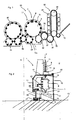
- FIG. 1 shows a schematic representation of a plant for producing plastic containers according to the prior art.
- This system 50 has a heating device 30 in which plastic preforms 10 are heated.
- these plastic preforms 10 are guided by means of a transport device 34, such as a revolving chain, through this heater 30 and thereby heated with a plurality of heating elements 31.
- This heating device 30 is followed by a transfer unit 36, which transfers the preforms 10 to a sterilization device 32.
- This sterilization device 32 has Here also a transport wheel 37 and on this transport wheel 37 or stationary sterilization elements can be arranged. In this area, for example, a sterilization by hydrogen peroxide gas or by electromagnetic radiation is possible. In particular, an internal sterilization of the preforms is carried out in this area.
- the reference numeral 20 denotes in its entirety a clean room, the outer boundaries are indicated here by the dotted line L.
- the clean room 20 is arranged not only in the region of the transport wheel 2 and filling device 40, but possibly already starts in the area of the heating device 30, the sterilization device 32, the plastic preform supply and / or the plastic preform production. It can be seen that this clean room 20 begins in the area of the sterilization unit 32. In this area, lock devices can be provided to introduce the plastic preforms into the clean room 20 without too much gas flowing inside the clean room and thus being lost.
- the clean room is, as indicated by the dashed line L, adapted to the outer shape of the individual plant components. In this way, the volume of the clean room can be reduced.
- the reference numeral 1 denotes in its entirety a forming device in which a plurality of blowing stations or forming stations 8 is arranged on a transport wheel 2, wherein only one of these blowing stations 8 is shown here. With these blowing stations 8, the plastic preforms 10 are expanded to containers 10a. Although not shown in detail here, not the entire area of the transport device 2 is located within the clean room 20, but the clean room 20 or insulator is effectively implemented as a mini-isolator within the entire device. Thus, it would be possible for the clean room to be channel-like, at least in the area of the forming device 1.
- the reference numeral 22 refers to a feeding device which transfers the preforms to the forming device 1 and the reference numeral 24 to a discharge device which discharges the produced plastic containers 20 from the forming device 1. It can be seen that the clean room 20 in the region of the feed device 22 and the discharge device 24 each have recesses which these devices 22, Record 24. In this way, a transfer of the plastic preforms 10 to the forming device 1 and a takeover of the plastic containers 10a of the forming device 1 can be achieved in a particularly advantageous manner.
- the expanded plastic containers are transferred to a filling device 40 and then discharged from this filling device 40 via a further transport unit 44.
- the filling device it would also be possible that not the entire filling device 40 with, for example, a reservoir for a beverage are arranged completely within the clean room 20, but also only those regions, where the containers are actually kept.
- the filling device could be constructed in a similar manner as the device 1 for forming plastic preforms 10th
- the clean room 20 in the area of the device 1 is reduced to a minimum possible area, namely substantially to the blowing stations 8 itself.
- This small-sized design of the clean room 20 makes it easier and faster to produce a clean room at all and also to maintain sterility in the operating phase is less expensive. Also, less sterile air is needed, resulting in smaller filter units and also the risk of uncontrolled vortex formation is reduced.
- FIG. 2 shows a detailed view of the device 1 according to the prior art in the region of a blowing station 8.
- a plurality of such blowing stations 8 is rotatably moved with a transport device 2 and a support about an axis X.
- the blowing station 8 is as in FIG. 2 can be seen within the clean room 20, which is here channel-like out.
- This clean room 20 is completed by a movable side wall 19 and a lid 17 integrally formed with this side wall 19. This side wall 19 and the cover 17 thereby rotate with the blowing station 8.
- the reference numeral 18 refers to a further wall which limits the clean room 20.
- This wall 18 is here an outer wall, which is arranged stationary.
- a sealing device 25 is provided, which seals the mutually movable elements 17 and 18 against each other, for example, as mentioned above, using a water lock.
- a support 26 is provided, which also moves in rotation and on which in turn a holding device 23 is provided, which holds the blowing station 8.
- the reference numeral 11 refers to a follower which can be actuated by a guide cam 9 to open and close the blow station on its way through the clean room 20, in particular to insert the plastic preform in the blowing station and to remove it again.
- a guide curve 9 is also arranged within the clean room 20.
- the transport device 2 may also have further elements, which are arranged above the clean room 20.
- the carrier 26 is fixedly arranged on a holding body 29 and this holding body is in turn movable relative to the bottom 13.
- the reference numeral 27 refers to a further sealing device, which causes a sealing of the mutually movable portions 13 and 29 in this area.
- the reference numeral 5 refers to a stretching rod which is movable with respect to the blowing station in order to stretch the plastic preforms 10 in their longitudinal direction.
- a carriage 12 is arranged on the lid 17, on the other hand, the stretch rod in the direction Y is movable.
- the reference numeral 21 refers to a further holder for this carriage 12 of the stretch rod. 5
- the reference character U denotes the (non-sterile) environment of the clean room 20.
- the reference numeral 28 denotes a support for supporting a bottom mold, which also has a Part of the blow mold forms. This carrier is also movable in the direction Y.
- the reference numeral 55 refers to a sterilization device, which is preferably arranged here in the interior of the clean room 20 and serves to sterilize the individual transformation stations or components of these conversion stations 8.
- This sterilization device 55 can act on the conversion stations 8, for example, with hydrogen peroxide or other sterilizing agent.
- the sterilization device 55 can be arranged stationary and the transformation stations can move relative to this sterilization device 55.
- This sterilization device or impinging device 55 may be located on the transport wheel 2 or on the stationary wall 18 or be arranged generally stationary and consist of nozzles or the like.
- the blow molds (not shown) are disposed inside the blow mold carriers 6. More precisely, two Blasformabomaschine can be arranged, which are pivotable relative to each other and each holding a blow mold. By this pivoting process, the blow molds for introducing plastic preforms and for removing finished blown containers can be opened. These blow mold carriers and blow molds are likewise arranged inside the clean room.
- the transport device 2 or the carrier has a C-shaped outer circumference, which also partially forms the outer walls of the clean room.
- this C - shaped clean room wall rotates here with the transport device 2, ie the blowing wheel.
- the lower boundary of the clean room is spaced from the floor 13 and moves relative to the floor. In this way, the clean room can be made even smaller than in Fig.2 shown.
- This outer wall is advantageously arranged stationary.
- FIG. 3 1 shows a representation of a blow station 8 arranged on a carrier 2.
- this carrier has three wall regions 82, 84, 86, which at the same time also form the rotating parts of a clean room boundary of the clean room 20.
- a sealing device such as a water lock, these movable parts 82, 84, 86 can be sealed against a movable (outer) wall.
- the reference numeral 56 denotes a valve block, which is arranged here above the wall 82 and the reference numeral 58 a blowing nozzle, which can be placed on the plastic preform in order to expand it.
- the blowing station furthermore has a blow mold carrier on which a blow molding part (here only one blow mold part 4a shown) is arranged. This blow mold can be pivoted by means of a pivot shaft 65 against each other, so as to open the blow molds and close.
- FIG. 4 shows a representation of a blow mold 4, more precisely two blow mold parts 4a, 4b, which are respectively arranged on Blasformizi former 6a, 6b.
- These Blasformizimaschine can be pivoted here by means of a pivot shaft, so as to open the blow mold 4 or close.
- the blow mold parts 4a, 4b are not arranged directly on the Blasformy former 6a, 6b, but on the Blasformizi former 6a, 6b support shells are arranged, on which in turn the blow mold parts 4a, 4b are attached.
- the pressure means can be provided, which can reduce a gap between the blow mold parts 4a, 4b especially for a sterilization process.
- the reference numeral 4 indicates the blow mold in its entirety.
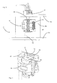
- FIG. 5 shows a sectional view of a blowing station according to the invention.
- a blow mold or a blow mold part 4a which is arranged in a blow mold carrier 6a, can also be seen here again.
- Reference numeral 60 denotes a bore which is disposed in the blow molding part 4a to discharge air during the expansion process.
- the reference numeral 67 denotes a bottom part which closes the blow mold from below. Also in this bottom part venting channels 69 may be arranged. These venting channels 69 are also in fluid communication with the clean room 20, which surrounds the blow mold.
- an additional element such as here a so-called SIP cap 70 may be provided.
- the sterilizing agent can be supplied to the blow molds.
- a sterilizing agent is supplied directly to the blow mold via the blowing nozzle 58 and the channels 74, 72 and 76, more precisely a channel system 62, 64 and that the sterilizing agent exits there via the bores 60 into the interior of the blow mold.
- this SIP cap 70 can direct by their special design introduced through the tuyere sterilization agent directly into the vent holes of the tuyeres.
- sealing devices such as O-rings are provided, which additionally seal the transitions, for example between the channel 76 and the channel 62 of the blow mold 4.
- sealing devices such as O-rings are provided, which additionally seal the transitions, for example between the channel 76 and the channel 62 of the blow mold 4.
- the said SIP or CIP cap can be dispensed with. If the tuyere blows directly into the interior of the tuyeres 4a, 4b, much of the sterilization media will escape through a mold gap between the two mold halves instead of choosing the path through the bleed holes. As mentioned above, remedial action can be taken by reducing the mold gap for sterilization.
- the sterilizing agent by introducing a component intended for this purpose (for example a so-called CIP piston).
- a component intended for this purpose for example a so-called CIP piston.
- This can be designed to be movable and dock for sterilization of the component to be sterilized.
- the component to be sterilized may be, for example, the blow molds.
- the actual sterilization can then be similar, as described above.
- the flow connection for sterilizing the clean room and also the objects and components is preferably produced by the blow piston or the blow nozzle.
- valves used to introduce the sterilization medium are used to introduce the sterilization medium. It is particularly preferably possible that valves used to introduce the sterilization medium remain open during the sterilization process. However, it would also be conceivable that valves used to introduce the sterilization medium are switched during the sterilization process, ie from an open to a closed state and / or vice versa.
- FIG. 6 shows a further illustration of a blow mold according to the invention, in which case also a sterilization path S for the sterilization medium can be seen.
- the sterilization medium is fed into the blow mold through a vertically extending channel 62 and finally exits via the opening 60.
- channel 72 is formed circumferentially and in this way an introduction into a plurality of channels 62 is possible.
- the SIP cap 70 is not in communication with the blow molds, and thus, during the expansion process, the blown air can escape upward into the clean room surrounding the blowing station.
- Reference numeral 66 denotes the cavity formed by the blow mold (shown only partially here).
- FIG. 7 shows a detailed illustration of a blow mold according to the invention. It can be seen that this blow mold has a channel 62, which establishes a flow connection between the opening 60 and the clean room 20. This channel 62 extends here in the vertical direction or the longitudinal direction Lr of the blow mold 4.
- a connecting channel 64 is provided, which connects the opening 60 with the channel 62.
- the channel 62 has a larger flow cross-section than the connecting channel 64.
- the channel 62 may moreover accommodate a plurality of such connecting channels 64, which may for example be arranged one above the other.
- channel 62 extends continuously along substantially the entire length of the blow mold 4, but it would also be conceivable that two channels 62 are provided, one of which is open upwards and one downwards.
- Reference numeral 63 denotes an inner wall of the blow mold.
Abstract
Description
Die vorliegende Erfindung bezieht sich auf eine Vorrichtung zum Umformen von Kunstoffvorformlingen zu Kunststoffbehältnissen. Derartige Vorrichtungen sind aus dem Stand der Technik seit langem bekannt. Dabei werden üblicherweise in einer Vielzahl von Blasstationen erwärmte Kunststoffvorformlinge durch Beaufschlagung mit Druckluft zu Kunststoffbehältnissen umgeformt.The present invention relates to an apparatus for forming plastic preforms into plastic containers. Such devices have been known for a long time from the prior art. In this case, heated plastic preforms are usually formed in a plurality of blowing stations by applying compressed air to plastic containers.
In jüngerer Zeit sind auch aseptische Blasformmaschinen bekannt geworden, bei denen der Umformungsvorgang innerhalb eines Reinraums stattfindet. Eine derartige Maschine ist aus der
Dabei ist aus dem internen Stand der Technik der Anmelderin auch bekannt, dass die Blasformen an ihrer Innenwandung kleine Öffnungen aufweisen können, um während des Blasvorgangs ein gasförmiges Medium, wie beispielsweise verdrängte Luft, abführen zu können. Die Sterilisation dieser Öffnungen stellt jedoch ein erhebliches Problem dar. Des Weiteren kann durch diese Öffnungen im Stand der Technik eine Kontamination der Blasformen verursacht werden.It is also known from the applicant's internal state of the art that the blow molds can have small openings on their inner wall in order to be able to remove a gaseous medium, such as displaced air, during the blowing process. However, the sterilization of these openings presents a significant problem. Furthermore, these openings in the prior art may cause contamination of the blow molds.
Beim Bau einer aseptischen Streckblasmaschine ist die Sterilisation des Reinraums und der darin befindlichen Teile entscheidend. Nur durch zuverlässige Sterilisation kann eine keimfreie Atmosphäre erreicht werden, die für die aseptische Herstellung von Behältern und die Abfüllung von Getränken bedeutsam ist.In the construction of an aseptic stretch blow molder, the sterilization of the clean room and its parts is crucial. Only through reliable sterilization can a germ-free atmosphere be achieved, which is important for the aseptic preparation of containers and the bottling of beverages.
Der vorliegenden Erfindung liegt daher die Aufgabe zugrunde, eine verbesserte Möglichkeit zu schaffen, um die Sterilität in einem derartigen Reinraum bzw. in einer derartigen Blasmaschine aufrecht zu erhalten. Dies wird erfindungsgemäß durch die unabhängigen Ansprüche erreicht. Vorteilhafte Ausführungsformen und Weiterbildungen sind Gegenstand der Unteransprüche.The present invention is therefore based on the object to provide an improved way to maintain the sterility in such a clean room or in such a blow molding machine. This is achieved according to the invention by the independent claims. Advantageous embodiments and further developments are the subject of the dependent claims.
Eine erfindungsgemäße Vorrichtung zum Umformen von Kunststoffvorformlingen zu Kunststoffbehältnissen weist wenigstens eine Blasform mit mindestens zwei bezüglich einander bewegbaren Blasformteilen auf. Diese Blasformteile bilden dabei einen Hohlraum aus, innerhalb dessen die Kunststoffvorformlinge zu den Kunststoffbehältnissen umformbar sind. Weiterhin weist die Vorrichtung eine Beaufschlagungsvorrichtung auf, welche die Kunststoffvorformlinge zu deren Expansion mit einem fließfähigen Medium beaufschlagt sowie eine Transporteinrichtung, welche die Blasform entlang eines vorgegebenen Transportpfades transportiert. Weiterhin weist die Vorrichtung einen Reinraum auf, innerhalb dessen die Blasform während der Expansion der Kunststoffvorformlinge transportierbar ist, wobei dieser Reinraum mittels wenigstens einer Wandung gegenüber einer unsterilen Umgebung abgegrenzt ist. Die Blasform weist dabei an einer den Kunststoffvorformlingen zugewandten Innenwandung wenigstens eine Öffnung auf, durch welche während des Expansionsvorgangs ein fließfähiges Medium aus dem Hohlraum abführbar ist.A device according to the invention for forming plastic preforms into plastic containers has at least one blow mold with at least two blow mold parts which are movable relative to one another. These blow moldings form a cavity, within which the plastic preforms are deformable to the plastic containers. Furthermore, the device has a loading device, which acts on the plastic preforms for their expansion with a flowable medium and a transport device which transports the blow mold along a predetermined transport path. Furthermore, the device has a clean room within which the blow mold can be transported during the expansion of the plastic preforms, wherein this clean room is delimited by means of at least one wall against an unsterile environment. In this case, the blow mold has at least one opening on an inner wall facing the plastic preforms, through which a flowable medium can be discharged from the cavity during the expansion process.
Erfindungsgemäß ist eine Strömungsverbindung zwischen dieser Öffnung und dem Reinraum vorgesehen und diese Strömungsverbindung ist gegenüber der unsterilen Umgebung des Reinraums abgedichtet.According to the invention, a flow connection is provided between this opening and the clean room and this flow connection is sealed off from the non-sterile environment of the clean room.
Es wird daher vorgeschlagen, dass über die besagten Öffnungen innerhalb der Blasform während des Expansionsvorgangs ein gasförmiges Medium ausschließlich in den Reinraum abgeführt wird und nicht in die unsterile Umgebung. Auf diese Weise kann umgekehrt eine Re-Kontamination des Reinraums durch die unsterile Umgebung verhindert werden.It is therefore proposed that via the said openings within the blow mold during the expansion process, a gaseous medium is discharged exclusively into the clean room and not in the non-sterile environment. In this way, conversely, a re-contamination of the clean room can be prevented by the non-sterile environment.
Bei einer vorteilhaften Ausführungsform weist die Vorrichtung eine Vielzahl von Blasformen bzw. Blasstationen auf. Genauer gesagt kann eine Vielzahl von Blasstationen vorgesehen sein, welche jeweils Blasformträger und an diesen Blasformträgern angeordnete Blasformen aufweisen können. Vorteilhaft handelt es sich bei der Transporteinrichtung um ein Blasrad, an dem eine Vielzahl von Blasstationen angeordnet ist. Bei einer weiteren vorteilhaften Ausführungsform ist der Reinraum bzw. Sterilraum kanalförmig um den Transportpfad der einzelnen Blasstationen ausgebildet.In an advantageous embodiment, the device has a plurality of blow molds or blowing stations. More specifically, a plurality of blow molding stations may be provided, which may each have blow mold carriers and blow molds arranged on these blow mold carriers. Advantageously, the transport device is a blowing wheel, on which a plurality of blowing stations is arranged. In a further advantageous embodiment, the clean room or sterile room is channel-shaped around the transport path of the individual blow molding stations.
Dabei ist es möglich, dass die einzelnen Träger mit den daran angeordneten Blasformen auseinanderklappbar sind, um in einem geöffneten Zustand die Kunststoffvorformlinge aufnehmen zu können.It is possible that the individual carriers with the blow molds arranged thereon can be folded apart in order to be able to receive the plastic preforms in an opened state.
Vorteilhaft sind an der Innenwandung der Blasformen eine Vielzahl der oben erwähnten Öffnungen angeordnet, um gleichmäßig die während des Expansionsvorgangs durch die entstehende Flasche verdrängte Luft, aufnehmen zu können. Bei einer weiteren vorteilhaften Ausführungsform ist der Reinraum wenigstens teilweise auch durch die Transporteinrichtung selbst ausgebildet.Advantageously, a plurality of the above-mentioned openings are arranged on the inner wall of the blow molds in order to be able to uniformly absorb the air displaced during the expansion process by the resulting bottle. In a further advantageous embodiment, the clean room is at least partially also formed by the transport device itself.
Bei einer weiteren vorteilhaften Ausführungsform weist die Vorrichtung eine Zuführleitung auf, um der Blasform ein fließfähiges Sterilisationsmedium zuzuführen, wobei wenigstens zeitweise eine Strömungsverbindung zwischen der Zuführleitung und der besagten Öffnung besteht. Über diese Zuführleitung können auch die Blasformen sterilisiert werden. Bei dem Sterilisationsmittel handelt es sich insbesondere um H2O2, es wäre jedoch auch möglich, beispielsweise Peressigsäure oder andere Sterilisationsmittel zu verwenden. Dabei ist es möglich, dass dieses Sterilisationsmittel über die besagten Bohrungen in den Hohlraum gelangt.In a further advantageous embodiment, the device has a feed line for supplying the blow mold to a flowable sterilization medium, at least temporarily having a flow connection between the feed line and the said opening. About this supply line and the blow molds can be sterilized. In particular, the sterilant is H 2 O 2 , but it would also be possible to use, for example, peracetic acid or other sterilant. It is possible that this sterilizing agent passes through said holes in the cavity.
Vorteilhaft wird die besagte Verbindung zwischen einem Reservoir für das Sterilisationsmedium und den zu sterilisierenden Bauteilen zeitweise zum Zwecke der Sterilisation hergestellt. Dies kann auf unterschiedliche Arten erfolgen. So wäre es beispielsweise möglich, eine Beaufschlagungseinrichtung, wie einen Blaskolben oder eine Blasdüse zum Einbringen des Sterilisationsmediums zu benutzen. Dabei kann auch die Blasdüse selbst sterilisiert werden. Weiterhin wäre es möglich, dass ein Sterilisationsgas aus der Blasdüse in den Isolator bzw. Reinraum entweicht und diesen sterilisiert. Zur Sterilisation von schwer erreichbaren Stellen wie beispielsweise den oben erwähnten Öffnungen bzw. Entlüftungsbohrungen in den Blasformen wäre es auch möglich, die Blasdüse auf die Blasformen aufzusetzen und das Sterilisationsmittel direkt in die Blasformen einzublasen.Advantageously, said connection between a reservoir for the sterilization medium and the components to be sterilized is temporarily produced for the purpose of sterilization. This can be done in different ways. Thus, it would be possible, for example, to use an admission device, such as a blow piston or a blow nozzle for introducing the sterilization medium. In this case, the nozzle itself can be sterilized. Furthermore, it would be possible for a sterilization gas to escape from the blowing nozzle into the isolator or clean room and to sterilize it. For the sterilization of difficult to reach Places such as the above-mentioned openings or vent holes in the blow molds, it would also be possible to put the nozzle on the blow molds and inject the sterilant directly into the blow molds.
Bei einer weiteren vorteilhaften Ausführungsform weist daher die Vorrichtung eine Bevorratungseinrichtung zum Bevorraten des fließfähigen Sterilisationsmediums auf und diese Bevorratungseinrichtung steht wenigstens zeitweise in Strömungsverbindung mit der oben erwähnten Öffnung (der Blasform). Auf diese Weise kann das Sterilisationsmedium über die Öffnung in die Blasform austreten.In a further advantageous embodiment, therefore, the device has a storage device for storing the flowable sterilization medium and this storage device is at least temporarily in flow communication with the above-mentioned opening (the blow mold). In this way, the sterilization medium can escape via the opening into the blow mold.
Bei einer weiteren vorteilhaften Ausführungsform verläuft die Strömungsverbindung wenigstens abschnittsweise über die Beaufschlagungseinrichtung. So ist es möglich, dass das Sterilisationsmittel ausgehend von der Beaufschlagungseinrichtung wie einer Blasdüse der Blasform zugeführt wird. Dies wird genauer unter Bezugnahme auf die Figuren erläutert.In a further advantageous embodiment, the flow connection extends at least in sections via the loading device. Thus, it is possible that the sterilizing agent is supplied to the blow mold starting from the loading device such as a blowing nozzle. This will be explained in more detail with reference to the figures.
Bei einer weiteren vorteilhaften Ausführungsform weist die Vorrichtung ein gegenüber der Blasform bewegliches Umleitelement auf, welches das Sterilisationsmedium in einen Sterilisationsbetrieb zu der Öffnung leitet. So ist es möglich, dass zur besseren Sterilisation der eventuell vorhandenen Entlüftungsbohrungen in den Blasformen ein zusätzliches Element, wie beispielsweise eine sogenannte SIP-Kappe benutzt wird. Dieses Bauteil kann dabei zwischen die Blasform bzw. die Blasformteile und die Blasdüse eingebracht werden. Anschließend ist es möglich, dass die Beaufschlagungseinrichtung bzw. die Blasdüse nach unten fährt und das Sterilisationsmittel in die besagte SIP-Kappe einbläst. Durch die spezielle Gestaltung kann die SIP-Kappe dann das durch die Blasdüse eingebrachte Sterilisationsmittel direkt in die Entlüftungsbohrungen der Blasformen einleiten. Dies bewirkt eine gute Durchspülung der Bohrungen mit Sterilisationsmittel und somit eine gute Sterilisation. Es sind jedoch auch andere Ausführungsformen der SIP-Kappe denkbar.In a further advantageous embodiment, the device has a bypass element which is movable relative to the blow mold and conducts the sterilization medium into a sterilization operation to the opening. Thus, it is possible that an additional element, such as a so-called SIP cap is used for better sterilization of any existing vent holes in the blow molds. This component can be introduced between the blow mold or blow moldings and the tuyere. Subsequently, it is possible that the loading device or the blowing nozzle moves down and blows the sterilizing agent in said SIP cap. Due to the special design, the SIP cap can then introduce the sterilization agent introduced through the tuyere directly into the vent holes of the tuyeres. This causes a good flushing of the holes with sterilant and thus a good sterilization. However, other embodiments of the SIP cap are also conceivable.
Weiterhin wäre es auch möglich, auf die besagte SIP- oder CIP-Kappe zu verzichten. Falls beispielsweise die Beaufschlagungseinrichtung bzw. Blasdüse das Sterilisationsmittel direkt in die Blasformen einbläst, wird ein Großteil des Sterilisationsmediums über einen Formspalt (dessen Größe üblicherweise im Bereich von 2/10 mm liegt) zwischen den beiden Formhälften entweichen, statt den Weg durch die Entlüftungsbohrungen zu wählen. Dieses Problem kann gelöst werden durch eine Vorrichtung, die es ermöglicht, den Formspalt während der Sterilisation soweit wie möglich zu verkleinern und danach für die Produktion wieder auf das benötigte Maß von ca. 0,2 mm zu bringen. Dieser Abstand von ca. 0,2 mm ist vorteilhaft, damit beim Expandieren der Behältnisse die Luft zwischen dem Behältnis und der Blasform aus der Form entweichen kann.Furthermore, it would also be possible to dispense with said SIP or CIP cap. For example, if the applicator or tuyere injects the sterilant directly into the tuyeres, much of the sterilant medium will escape through a mold gap (the size of which is usually in the range of 2/10 mm) between the two mold halves instead of choosing the path through the vent holes , This problem can be solved by a device that allows the mold gap during the Minimize sterilization as far as possible and then bring it back to the required dimension of approx. 0.2 mm for production. This distance of about 0.2 mm is advantageous so that the air between the container and the blow mold can escape from the mold when expanding the containers.
Weiterhin wäre es auch möglich, das Sterilisationsmittel über ein eigens zu diesem Zweck bestimmtes Bauteil, wie etwa einen sogenannten SIP-Kolben, durchzuführen. Dieser kann beweglich ausgeführt sein und zum Sterilisieren an das zu sterilisierende Bauteil andocken. Dies können dann ebenfalls die Blasformen sein. Die eigentliche Sterilisation kann dann ähnlich erfolgen wie oben beschrieben.Furthermore, it would also be possible to carry out the sterilizing agent via a component intended for this purpose, such as a so-called SIP piston. This can be designed to be movable and dock for sterilization of the component to be sterilized. These can then also be the blow molds. The actual sterilization can then be done similarly as described above.
Bei einer weiteren vorteilhaften Ausführungsform weist die Blasform wenigstens einen Kanal zum Leiten des fließfähigen Mediums und/oder des Sterilisationsmediums auf, wobei dieser Kanal in Strömungsverbindung mit der Öffnung steht und sich der Kanal in einer Längsrichtung der Blasform erstreckt. Vorteilhaft ist dabei dieser Kanal in einer Innenwandung der Blasform ausgebildet. Besonders bevorzugt ist der besagte Kanal vollständig in der besagten Innenwandung ausgebildet. Weiterhin ist es auch möglich, dass dieser Kanal in Strömungsverbindung mit dem Reinraum steht.In a further advantageous embodiment, the blow mold has at least one channel for conducting the flowable medium and / or the sterilization medium, wherein this channel is in flow communication with the opening and the channel extends in a longitudinal direction of the blow mold. Advantageously, this channel is formed in an inner wall of the blow mold. Particularly preferably, said channel is completely formed in said inner wall. Furthermore, it is also possible that this channel is in flow communication with the clean room.
Die vorliegende Erfindung ist weiterhin auf eine Blasform zum Umformen von Kunststoffvorformlingen zu Kunststoffbehältnissen gerichtet. Diese Blasform weist wenigstens ein erstes Blasformteil und ein zweites Blasformteil auf, wobei diese beiden Blasformteile bezüglich einander bewegbar sind und die Blasformteile einen Hohlraum ausbilden, innerhalb dessen die Kunststoffvorformlinge durch Beaufschlagung mit einem gasförmigen Medium zu den Kunststoffbehältnissen expandierbar sind. Weiterhin weist die Blasform bzw. weisen die Blasformteile in einer den Kunststoffvorformlingen zugewandten Wandung der Blasform wenigstens eine Öffnung auf, um während des Expansionsvorgangs ein gasförmiges Medium abzuführen und/oder um während des Sterilisationsvorgangs der Blasform ein fließfähiges Sterilisationsmedium zuzuführen. Vorteilhaft steht diese Öffnung in Strömungsverbindung mit einem innerhalb einer Wandung der Blasform bzw. der Blasformteile verlaufenden Kanal und dieser Kanal erstreckt sich wenigstens abstandsweise in einer Längsrichtung der Blasform. Es wird daher auch hinsichtlich der Blasform vorgeschlagen, dass diese in ihrem Inneren einen Kanal aufweist, der insbesondere zum Abführen von Luft aus der geschlossenen Blasform dienen kann, gegebenenfalls jedoch auch zur Zuführung eines Sterilisationsmediums.The present invention is further directed to a blow mold for forming plastic preforms into plastic containers. This blow mold has at least a first blow molded part and a second blow molded part, wherein these two blow moldings are movable relative to each other and the blow moldings form a cavity within which the plastic preforms are expandable by exposure to a gaseous medium to the plastic containers. Furthermore, the blow mold or the blow moldings have at least one opening in a wall of the blow mold facing the plastic preforms in order to remove a gaseous medium during the expansion process and / or to supply a flowable sterilization medium to the blow mold during the sterilization process. Advantageously, this opening is in fluid communication with a channel extending within a wall of the blow mold or blow moldings, and this channel extends at least at intervals in a longitudinal direction of the blow mold. It is therefore also proposed in terms of the blow mold that this has in its interior a channel which can serve in particular for the removal of air from the closed blow mold, but optionally also for supplying a sterilization medium.
Im Stand der Technik sind zwar die besagten Öffnungen in der Innenwandung der Blasformen bekannt, die sich an diese Öffnung anschließenden Kanäle erstrecken sich jedoch üblicherweise in radialer Richtung, was aus fertigungstechnischen Gründen einfacher ist, als die hier vorgeschlagene Vorgehensweise. Mit der hier vorgeschlagenen Vorgehensweise ist es jedoch auch möglich, das gasförmige Medium, d.h. insbesondere die Blasluft, in der Längsrichtung des Behältnisses in den Reinraum zu führen.Although the said openings in the inner wall of the blow molds are known in the prior art, the channels adjoining this opening usually extend in the radial direction, which is simpler for manufacturing reasons than the procedure proposed here. However, with the approach proposed herein, it is also possible to use the gaseous medium, i. in particular, the blowing air to lead in the longitudinal direction of the container in the clean room.
Bei einer vorteilhaften Ausführungsform steht der innerhalb der Wandung verlaufende Kanal über einen Verbindungskanal mit der Öffnung in Strömungsverbindung. Dieser Verbindungskanal kann dabei auch in einer radialen Richtung der Blasform verlaufen.In an advantageous embodiment, the channel extending within the wall is in fluid communication with the opening via a connecting channel. This connection channel can also run in a radial direction of the blow mold.
Vorteilhaft steht der besagte Kanal mit mehreren der oben genannten Öffnungen in Strömungsverbindung. Dabei können diese Öffnungen beispielsweise in der Längsrichtung der Blasform übereinander angeordnet sein. Weiterhin wäre es auch möglich, dass eine Vielzahl der genannten Kanäle innerhalb der Wandung der Blasform bzw. der Blasformteile ausgebildet sind.Advantageously, said channel is in flow communication with a plurality of the above-mentioned openings. In this case, these openings may be arranged one above the other, for example in the longitudinal direction of the blow mold. Furthermore, it would also be possible that a plurality of said channels are formed within the wall of the blow mold or blow moldings.
Die vorliegende Erfindung ist weiterhin auf ein Verfahren zum Umformen von Kunststoffvorformlingen zu Kunststoffbehältnissen gerichtet, wobei die Kunststoffvorformlinge in einer Vielzahl von Blasstationen bzw. Blasformen zu den Kunststoffbehältnissen umgeformt werden und die Blasformen mittels einer Transporteinrichtung zumindest teilweise während ihrer Expansion entlang eines vorgegebenen Transportpfades innerhalb eines Reinraums transportiert werden, wobei wenigstens zeitweise während des Expansionsvorgangs ein gasförmiges Medium über eine in einer den Kunststoffvorformlingen zugewandten Wandung der Blasform angeordnete Öffnung abgeführt wird und/oder wenigstens zeitweise während eines Sterilisationsvorgangs ein fließfähiges Medium über die den Kunststoffvorformlingen zugewandte Öffnung der Blasform zugeführt wird.The present invention is further directed to a method of forming plastic preforms into plastic containers wherein the plastic preforms are formed into the plastic containers in a plurality of blow stations and the blow molding by means of a transport means at least partially during their expansion along a predetermined transport path within a clean room be transported, wherein at least temporarily during the expansion process, a gaseous medium via a arranged in the plastic preforms wall of the blow mold opening is removed and / or at least temporarily during a sterilization process, a flowable medium via the plastic preforms facing opening of the blow mold is supplied.
Erfindungsgemäß gelangt das gasförmige Medium ausgehend von der Öffnung ausschließlich in den Reinraum.According to the gaseous medium from the opening passes exclusively into the clean room.
Es wird daher auch verfahrensseitig vorgeschlagen, dass das gasförmige Medium, wie beispielsweise die Blasluft oder innerhalb der Blasform befindliche Luft, die über die Öffnungen abgeführt wird, dabei jedoch nicht in die Umgebung gelangt, sondern lediglich in den Reinraum. Auf diese Weise wird auch verfahrensseitig das Sterilhalten der einzelnen Blasstationen und auch des Reinrauminneren erleichtert.It is therefore also proposed on the method side, that the gaseous medium, such as the blowing air or air located within the blow mold, which is discharged through the openings, but does not get into the environment, but only in the clean room. In this way, the sterilization of the individual blowing stations and also of the cleanroom interior is facilitated on the procedural side.
Weitere Vorteile und Ausführungsformen ergeben sich aus den beigefügten Zeichnungen:Further advantages and embodiments will be apparent from the attached drawings:
- Fig. 1Fig. 1
- eine schematische Darstellung einer Anlage zum Herstellen von Kunststoffbehältnissen;a schematic representation of a plant for the production of plastic containers;
- Fig. 2Fig. 2
- eine Ansicht eines Reinraums im Bereich einer Blasstation;a view of a clean room in the area of a blowing station;
- Fig. 3Fig. 3
- eine Darstellung einer erfindungsgemäßen Blasform, die an einem Träger angeordnet ist;an illustration of a blow mold according to the invention, which is arranged on a support;
- Fig. 4Fig. 4
- eine Darstellung einer in einem Blasformträger angeordneten Blasforman illustration of a blow mold arranged in a blow mold
- Fig. 5Fig. 5
- eine Darstellung einer geöffneten Blasstation mit Sicht auf die Blasform;a representation of an open blowing station with a view of the blow mold;
- Fig. 6Fig. 6
- eine Darstellung zur Veranschaulichung eines Sterilisationsmittelverlaufs;a representation for illustrating a Sterilisationsmittelverlaufs;
- Fig. 7Fig. 7
- eine Detaildarstellung einer Blasform.a detailed representation of a blow mold.
Das Bezugszeichen 20 bezeichnet in seiner Gesamtheit einen Reinraum, dessen Außenbegrenzungen hier durch die punktierte Linie L angedeutet sind. In einer weiteren bevorzugten Ausführungsform ist der Reinraum 20 nicht nur im Bereich des Transportrads 2 und Befüllungseinrichtung 40 angeordnet, sondern beginnt möglicherweise schon im Bereich der Heizeinrichtung 30, der Sterilisationseinrichtung 32, der Kunststoffvorformlingzuführung und/oder der Kunststoffvorformlingherstellung. Man erkennt, dass dieser Reinraum 20 in dem Bereich der Sterilisationseinheit 32 beginnt. In diesem Bereich können Schleuseneinrichtungen vorgesehen sein, um die Kunststoffvorformlinge in den Reinraum 20 einzuführen, ohne dass dabei zu viel Gas innerhalb des Reinraums strömt und so verloren geht.The
Der Reinraum ist, wie durch die gestrichelte Linie L angedeutet, an die Außengestalt der einzelnen Anlagenkomponenten angepasst. Auf diese Weise kann das Volumen des Reinraums reduziert werden.The clean room is, as indicated by the dashed line L, adapted to the outer shape of the individual plant components. In this way, the volume of the clean room can be reduced.
Das Bezugszeichen 1 bezeichnet in ihrer Gesamtheit eine Umformungsvorrichtung, bei der an einem Transportrad 2 eine Vielzahl von Blasstationen bzw. Umformungsstationen 8 angeordnet ist, wobei hier lediglich einer dieser Blasstationen 8 dargestellt ist. Mit diesen Blasstationen 8 werden die Kunststoffvorformlinge 10 zu Behältnissen 10a expandiert. Obwohl hier nicht detailliert gezeigt, befindet sich nicht der gesamte Bereich des Transporteinrichtung 2 innerhalb des Reinraums 20, sondern der Reinraum 20 bzw. Isolator ist gewissermaßen als Mini-Isolator innerhalb der gesamten Vorrichtung realisiert. So wäre es möglich, dass der Reinraum zumindest im Bereich der Umformungsvorrichtung 1 kanalartig ausgeführt ist.The reference numeral 1 denotes in its entirety a forming device in which a plurality of blowing stations or forming
Das Bezugszeichen 22 bezieht sich auf eine Zuführeinrichtung, welche die Vorformlinge an die Umformungseinrichtung 1 übergibt und das Bezugszeichen 24 auf eine Abführeinrichtung, welche die hergestellten Kunststoffbehältnisse 20 von der Umformungsvorrichtung 1 abführt. Man erkennt, dass der Reinraum 20 in dem Bereich der Zuführeinrichtung 22 und der Abführeinrichtung 24 jeweils Ausnehmungen aufweist, welche diese Einrichtungen 22, 24 aufnehmen. Auf diese Weise kann in besonders vorteilhafter Weise eine Übergabe der Kunststoffvorformlinge 10 an die Umformungsvorrichtung 1 bzw. eine Übernahme der Kunststoffbehältnisse 10a von der Umformungsvorrichtung 1 erreicht werden.The
Mit einer Übergabeeinheit 42 werden die expandierten Kunststoffbehältnisse an eine Befüllungseinrichtung 40 übergeben und von dieser Befüllungseinrichtung 40 anschließend über eine weitere Transporteinheit 44 abgeführt. Dabei befindet sich auch die Befüllungseinrichtung 40 innerhalb des besagten Reinraums 20. Auch im Falle der Befüllungseinrichtung wäre es möglich, dass nicht die gesamte Befüllungseinrichtung 40 mit beispielsweise einem Reservoir für ein Getränk vollständig innerhalb des Reinraums 20 angeordnet sind, sondern auch hier lediglich diejenigen Bereiche, in denen tatsächlich die Behältnisse geführt werden. Insoweit könnte auch die Befüllungseinrichtung in ähnlicher Weise aufgebaut sein wie die Vorrichtung 1 zum Umformen von Kunststoffvorformlingen 10.With a
Wie erwähnt, ist der Reinraum 20 im Bereich der Vorrichtung 1 auf einen geringst möglichen Bereich reduziert, nämlich im Wesentlichen auf die Blasstationen 8 selbst. Durch diese kleinbauende Gestaltung des Reinraums 20 ist es leichter und schneller möglich, einen Reinraum überhaupt herzustellen und auch die Sterilhaltung in der Betriebsphase ist weniger aufwändig. Auch wird weniger Sterilluft benötigt, was zu kleineren Filteranlagen führt und auch die Gefahr von unkontrollierter Wirbelbildung wird reduziert.As mentioned, the
Das Bezugszeichen 18 bezieht sich auf eine weitere Wandung, welche den Reinraum 20 begrenzt. Diese Wandung 18 ist hier eine außen liegende Wandung, welche stationär angeordnet ist. Zwischen dem Deckel 17 und der Wandung 18 ist eine Dichtungseinrichtung 25 vorgesehen, welche die gegeneinander beweglichen Elemente 17 und 18 gegeneinander abdichtet, beispielsweise, wie oben erwähnt, unter Verwendung eines Wasserschlosses. Der untere Bereich der Wandung 18 ist fest und abdichtend an einem Boden 13 angeordnet. Innerhalb des Reinraums 20 und hier unmittelbar an der Wandung 19 anliegend ist ein Träger 26 vorgesehen, der sich ebenfalls drehend bewegt und an dem wiederum eine Halteeinrichtung 23 vorgesehen ist, welche die Blasstation 8 hält.The
Das Bezugszeichen 11 bezieht sich auf eine Folgeeinrichtung, welche von einer Führungskurve 9 betätigt werden kann, um die Blasstation auf ihrem Weg durch den Reinraum 20 zu öffnen und zu schließen, um insbesondere den Kunststoffvorformling in die Blasstation einzulegen und um ihn auch wieder zu entnehmen. Dabei ist eine Führungskurve 9 auch innerhalb des Reinraums 20 angeordnet. Es wäre jedoch beispielsweise auch möglich, etwa bereits einen Abschnitt 11 unterhalb der einzelnen Blasstationen 8 aus dem Reinraum 20 herauszuführen.The
Die Transporteinrichtung 2 kann noch weitere Elemente aufweisen, welche oberhalb des Reinraums 20 angeordnet sind.The
Der Träger 26 ist dabei fest auf einem Haltekörper 29 angeordnet und dieser Haltekörper ist wiederum beweglich gegenüber dem Boden 13. Dabei bezieht sich das Bezugszeichen 27 auf eine weitere Dichtungseinrichtung, welche auch in diesem Bereich eine Abdichtung der gegeneinander beweglichen Bereiche 13 und 29 bewirkt.The
Das Bezugszeichen 5 bezieht sich auf eine Reckstange, welche gegenüber der Blasstation beweglich ist, um die Kunststoffvorformlinge 10 in ihrer Längsrichtung zu recken. Dabei ist auf dem Deckel 17 hier ein Schlitten 12 angeordnet, demgegenüber die Reckstange in der Richtung Y beweglich ist. Das Bezugszeichen 21 bezieht sich auf eine weitere Halterung für diesen Schlitten 12 der Reckstange 5.The reference numeral 5 refers to a stretching rod which is movable with respect to the blowing station in order to stretch the plastic preforms 10 in their longitudinal direction. In this case, a
Man erkennt, dass bestimmte Bereiche der Reckstange während des Blasvorgangs sowohl außerhalb des Reinraums 20 als auch innerhalb des Reinraums 20 sind. Zu diesem Zweck ist es möglich, außerhalb des Reinraums 20 bzw. oberhalb des Schlittens 12 eine Schutzeinrichtung wie einen Faltenbalg 14 vorzusehen, der die Reckstange 5 umgibt, so dass kein Bereich der Reckstange 5 unmittelbar mit der Außenumgebung in Berührung kommt. Das Bezugszeichen U kennzeichnet die (unsterile) Umgebung des Reinraums 20. Das Bezugszeichen 28 kennzeichnet einen Träger zum Tragen einer Bodenform, welche ebenfalls einen Bestandteil der Blasform ausbildet. Dieser Träger ist dabei ebenfalls in der Richtung Y bewegbar.It can be seen that certain areas of the stretch rod during the blowing process are both outside of the
Das Bezugszeichen 55 bezieht sich auf eine Sterilisationseinrichtung, welche hier bevorzugt im Inneren des Reinraums 20 angeordnet ist und zum Sterilisieren der einzelnen Umformungsstationen bzw. Bestandteilen dieser Umformungsstationen 8 dient. Diese Sterilisationseinrichtung 55 kann dabei die Umformungsstationen 8 beispielsweise mit Wasserstoffperoxid oder einem anderen Sterilisationsmittel beaufschlagen. Dabei kann die Sterilisationseinrichtung 55 stationär angeordnet sein und die Umformungsstationen können sich gegenüber dieser Sterilisationseinrichtung 55 bewegen. Diese Sterilisationseinrichtung bzw. Beaufschlagungseinrichtung 55 kann sich am Transportrad 2 oder an der stehenden Wandung 18 befinden oder generell stationär angeordnet sein und aus Düsen oder ähnlichem bestehen. Zudem ist es vorteilhaft, Sterilluft zum Sterilisieren des Reinraums 20 über das Lüftungssystem in den Reinraum 20 einzubringen.The
Die (nicht gezeigten) Blasformen sind innerhalb der Blasformträger 6 angeordnet. Genauer können dabei zwei Blasformträgerteile angeordnet sein, die gegenüber einander schwenkbar sind und jeweils ein Blasformteil halten. Durch diesen Schwenkvorgang können die Blasformen zum Einbringen von Kunststoffvorformlingen und zum Entnehmen fertig geblasener Behältnisse geöffnet werden. Diese Blasformträger und Blasformen sind dabei ebenfalls innerhalb des Reinraums angeordnet.The blow molds (not shown) are disposed inside the
Es wäre jedoch auch (anders als in
Das Bezugszeichen 56 kennzeichnet einen Ventilblock, der hier oberhalb der Wandung 82 angeordnet ist und das Bezugszeichen 58 eine Blasdüse, die auf den Kunststoffvorformling aufgesetzt werden kann, um diesen zu expandieren. Die Blasstation weist weiterhin einen Blasformträger auf, an dem ein Blasformteil (hier nur ein Blasformteil 4a gezeigt) angeordnet ist. Diese Blasformträger können mithilfe einer Schwenkwelle 65 gegeneinander verschwenkt werden, um so die Blasformen zu öffnen und zu schließen.The
Zur verbesserten Sterilisation der besagten Entlüftungsbohrungen in den Blasformen kann ein zusätzliches Element, wie hier eine sogenannte SIP-Kappe 70, vorgesehen sein. Durch ihre Gestaltung, welche hier die Kanäle 72, 74 und 76 umfasst, kann das Sterilisationsmittel den Blasformen zugeführt werden. So ist es möglich, dass ein Sterilisationsmittel über die Blasdüse 58 und die Kanäle 74, 72 und 76 direkt der Blasform zugeführt wird, genauer gesagt ein Kanalsystem 62, 64 und dass das Sterilisationsmittel von dort über die Bohrungen 60 in das Innere der Blasform austritt. Damit kann diese SIP-Kappe 70 durch ihre spezielle Gestaltung das durch die Blasdüse eingebrachte Sterilisationsmittel direkt in die Entlüftungsbohrungen der Blasformen leiten.For improved sterilization of said vent holes in the blow molds, an additional element, such as here a so-called
Es wäre weiterhin möglich, dass Dichtungseinrichtungen, wie O-Ringe vorgesehen sind, welche die Übergänge, beispielsweise zwischen dem Kanal 76 und dem Kanal 62 der Blasform 4 zusätzlich abdichten. Auf diese Weise wird eine gute Durchspülung der Bohrungen mit Sterilisationsmittel und somit eine gute Sterilisation ermöglicht. Es wären jedoch auch Ausführungsformen denkbar, bei denen auf die besagte SIP- oder CIP-Kappe verzichtet werden kann. Falls die Blasdüse direkt in den Innenraum der Blasformen 4a, 4b einbläst, wird ein Großteil der Sterilisationsmedien über einen Formspalt zwischen den beiden Formhälften entweichen, statt den Weg durch die Entlüftungsbohrungen zu wählen. Wie oben erwähnt, kann Abhilfe dadurch geschaffen werden, dass für die Sterilisation der Formspalt verringert wird.It would also be possible that sealing devices, such as O-rings are provided, which additionally seal the transitions, for example between the
Weiterhin wäre es auch möglich, das Sterilisationsmittel dadurch einzubringen, dass ein extra zu diesem Zweck bestimmtes Bauteil (zum Beispiel ein sogenannter CIP-Kolben) eingeführt wird. Dieser kann beweglich ausgeführt sein und zum Sterilisieren an das zu sterilisierende Bauteil andocken. Bei dem zu sterilisierende Bauteil kann es sich beispielsweise um die Blasformen handeln. Die eigentliche Sterilisation kann dann ähnlich erfolgen, wie oben beschrieben. Bevorzugt wird jedoch die Strömungsverbindung zum Sterilisieren des Reinraums und auch der Objekte und Bauteile durch den Blaskolben bzw. die Blasdüse hergestellt.Furthermore, it would also be possible to introduce the sterilizing agent by introducing a component intended for this purpose (for example a so-called CIP piston). This can be designed to be movable and dock for sterilization of the component to be sterilized. The component to be sterilized may be, for example, the blow molds. The actual sterilization can then be similar, as described above. However, the flow connection for sterilizing the clean room and also the objects and components is preferably produced by the blow piston or the blow nozzle.
Bei einer weiteren Ausführungsform wäre es auch denkbar, dass zum Einleiten des Sterilisationsmediums vorhandene Blasventile genutzt werden. Dabei ist es besonders bevorzugt möglich, dass zum Einleiten des Sterilisationsmediums verwendete Ventile während des Sterilisationsvorgangs geöffnet bleiben. Es wäre jedoch auch denkbar, dass zum Einleiten des Sterilisationsmediums verwendete Ventile während des Sterilisationsvorgangs geschaltet werden, d.h. von einem geöffneten in einen geschlossenen Zustand und/oder umgekehrt.In a further embodiment, it would also be conceivable that existing blow valves are used to introduce the sterilization medium. It is particularly preferably possible that valves used to introduce the sterilization medium remain open during the sterilization process. However, it would also be conceivable that valves used to introduce the sterilization medium are switched during the sterilization process, ie from an open to a closed state and / or vice versa.
Die Anmelderin behält sich vor sämtliche in den Anmeldungsunterlagen offenbarten Merkmale werden als erfindungswesentlich zu beanspruchen, sofern sie einzeln oder in Kombination gegenüber dem Stand der Technik neu sind.The applicant reserves the right to claim all features disclosed in the application documents as essential to the invention, provided that they are novel individually or in combination with respect to the prior art.
- 11
- Umformungsvorrichtungforming device
- 22
- TransportradTransport wheel
- 44
- Blasformblow
- 4a, 4b4a, 4b
- Blasformteileblow molded parts
- 55
- Reckstangestretching rod
- 66
- Blasformträgerblow mold
- 6a, 6b6a, 6b
- BlasformträgerteileBlasformträgerteile
- 88th
- Blas-/UmformungsstationenBlowing / forming stations
- 99
- Führungskurveguide curve
- 1010
- KunststoffvorformlingeThe plastic preforms
- 10a10a
- Behältnissecontainers
- 1111
- Folgeeinrichtungfollower
- 1212
- Schlittencarriage
- 1313
- Bodenground
- 1414
- Faltenbalgbellow
- 1717
- Deckelcover
- 1818
- weitere Wandunganother wall
- 1919
- SeitenwandSide wall
- 2020
- Reinraumcleanroom
- 2121
- Halterung für SchlittenHolder for sled
- 2222
- Zuführeinrichtungfeeding
- 2323
- Halteeinrichtungholder
- 2424
- Abführeinrichtungremoval device
- 2525
- Dichtungseinrichtungseal means
- 2626
- Trägercarrier
- 2727
- weitere Dichtungseinrichtungfurther sealing device
- 2828
- Träger zum Tragen einer BodenformCarrier for carrying a floor mold
- 2929
- Haltekörperholding body
- 3030
- Heizeinrichtungheater
- 3131
- Heizelementeheating elements
- 3232
- Sterilisationseinrichtungsterilization device
- 3434
- Transporteinrichtungtransport means
- 3636
- ÜbergabeeinheitTransfer unit
- 3737
- TransportradTransport wheel
- 4040
- Befüllungseinrichtungfilling device
- 4242
- ÜbergabeeinheitTransfer unit
- 4444
- Transporteinheittransport unit
- 5050
- Anlage zum Herstellen von KunststoffbehältnissenPlant for the production of plastic containers
- 5555
- Sterilisationseinrichtungsterilization device
- 5656
- Ventilblockmanifold
- 5858
- Blasdüseblow nozzle
- 6060
- Öffnung, BohrungOpening, bore
- 6262
- Kanalchannel
- 6363
- Innenwandung der BlasformInner wall of the blow mold
- 6464
- Verbindungskanalconnecting channel
- 6565
- Schwenkwellepivot shaft
- 6666
- Hohlraumcavity
- 6767
- Bodenteilthe bottom part
- 6969
- Entlüftungskanäleventilation ducts
- 7070
- Umleitelement, SIP - KappeDiverting element, SIP cap
- 72,74,7672,74,76
- Kanälechannels
- 82, 84, 8682, 84, 86
- durch den Träger ausgebildete Wandungen des Reinraums 20formed by the carrier walls of the clean room 20th
- LrLr
- Längsrichtung der BlasformLongitudinal direction of the blow mold
- UU
- unsterile Umgebungunsterile environment
- XX
- Schwenkachseswivel axis
- YY
- Schwenkwellepivot shaft
Claims (9)
dadurch gekennzeichnet, dass
eine Strömungsverbindung zwischen der Öffnung (60) und dem Reinraum (20) vorgesehen ist und diese Strömungsverbindung gegenüber einer unsterilen Umgebung des Reinraums (20) abgedichtet ist.Device (1) for forming plastic preforms (10) into plastic containers (10a) having at least one blow mold (4) with at least two blow molding parts (4a, 4b) which blow mold (4) forms a cavity within which the plastic preforms (10) 10) to the plastic containers (10a) are deformable, with a loading device (58) which acts on the plastic preforms (10) to expand with a flowable medium, with a transport device (2) which the blow mold (4) along a predetermined transport path transported and with a clean room (20), within which the blow mold (4) during the expansion of the plastic preforms (10) is transportable, wherein the blow mold (4) on an inner wall facing the plastic preform at least one opening (60) through which during the expansion process, a flowable medium from the cavity (69) can be discharged,
characterized in that
a flow connection between the opening (60) and the clean room (20) is provided and this flow connection is sealed against an unsterile environment of the clean room (20).
dadurch gekennzeichnet, dass
die Vorrichtung eine Zuführleitung aufweist, um der Blasform eine fließfähiges Sterilisationsmedium zuzuführen und wenigstens zeitweise eine Strömungsverbindung zwischen der Zuführleitung und der Öffnung (60) besteht.Device (1) according to claim 1,
characterized in that
the apparatus comprises a supply line for supplying a blow-by sterilizing medium to the blow mold and at least temporarily having a flow connection between the supply line and the opening (60).
dadurch gekennzeichnet, dass
die Vorrichtung (1) eine Bevorratungseinrichtung zum Bevorraten des fließfähigen Sterilisationsmediums aufweist und diese Bevorratungseinrichtung wenigstens zeitweise in Strömungsverbindung mit der Öffnung (60) steht.Device (1) according to claim 2,
characterized in that
the device (1) has a storage device for storing the flowable sterilization medium and this storage device at least temporarily is in flow communication with the opening (60).
dadurch gekennzeichnet, dass
die Strömungsverbindung abschnittsweise über die Beaufschlagungseinrichtung (58) verläuft.Device according to at least one of the preceding claims 2 - 3
characterized in that
the flow connection extends in sections via the loading device (58).
dadurch gekennzeichnet, dass
die Vorrichtung (1) ein gegenüber der Blasform (4) bewegliches Umleitelement (70) aufweist.Device according to at least one of the preceding claims,
characterized in that
the device (1) has a relative to the blow mold (4) movable Umleitelement (70).
dadurch gekennzeichnet, dass
die Blasform (4) wenigstens einen Kanal (62) zum Leiten des fließfähigen Mediums und/oder des Sterilisationsmediums aufweist, der in Strömungsverbindung mit der Öffnung steht und der sich in einer Längsrichtung (Lr) der Blasform (4) erstreckt.Device according to claim 1,
characterized in that
the blow mold (4) has at least one channel (62) for conducting the flowable medium and / or the sterilization medium, which is in flow communication with the opening and which extends in a longitudinal direction (Lr) of the blow mold (4).
die Öffnung (60) in Strömungsverbindung mit einem innerhalb einer Wandung der Blasform (4a, 4b) verlaufenden Kanal (62) steht und dieser Kanal (62) sich in einer Längsrichtung (Lr) der Blasform (4a, 4b) erstreckt.Blow mold (4) for forming plastic preforms (10) to plastic containers (10a), wherein the blow mold (4) at least a first blow molding (4a) and a second blow molding (4b) and the two blow moldings (4a, 4b) with respect to each other movable are and the blow moldings (4a, 4b) form a cavity within which the plastic preforms (10) by applying a gaseous medium to the plastic containers (10a) are expandable and wherein in a the plastic preforms (10) facing wall (63) of the blow mold (4) at least one opening (60) is provided to discharge a gaseous medium during an expansion process and / or to supply a flowable sterilization medium to the blow mold during a sterilization process, characterized in that
the orifice (60) is in fluid communication with a channel (62) extending within a wall of the blow mold (4a, 4b), said passage (62) extending in a longitudinal direction (Lr) of the blow mold (4a, 4b).
dadurch gekennzeichnet, dass
der innerhalb der Wandung (61) verlaufende Kanal (62) über einen Verbindungskanal (64) mit der Öffnung (60) in Strömungsverbindung steht.Blow mold according to claim 7,
characterized in that
the channel (62) running inside the wall (61) is in fluid communication with the opening (60) via a connecting channel (64).
dadurch gekennzeichnet, dass
das gasförmige Medium ausgehend von der Öffnung (60) ausschließlich in den Reinraum (20) gelangt.A method of forming plastic preforms (10) into plastic containers (10a), wherein the plastic preforms (10) in a plurality of blow molds (4) to the plastic containers (10a) are transformed and the blow molds (4) by means of a transport device (2) at least partially be transported during their expansion along a predetermined transport path within a clean room (20) and wherein at least temporarily during the expansion process, a gaseous medium via a in the plastic preforms (10) facing wall (61) of the blow mold (4) arranged opening (60) removed and / or at least temporarily during a sterilization process, a flowable medium is supplied via the plastic preforms facing the opening of the blow mold,
characterized in that
the gaseous medium, starting from the opening (60) passes exclusively into the clean room (20).
Applications Claiming Priority (1)
| Application Number | Priority Date | Filing Date | Title |
|---|---|---|---|
| DE201110101256 DE102011101256A1 (en) | 2011-05-11 | 2011-05-11 | Aseptic blow molding machine with sterile air discharge |
Publications (2)
| Publication Number | Publication Date |
|---|---|
| EP2522485A1 true EP2522485A1 (en) | 2012-11-14 |
| EP2522485B1 EP2522485B1 (en) | 2016-01-13 |
Family
ID=46178407
Family Applications (1)
| Application Number | Title | Priority Date | Filing Date |
|---|---|---|---|
| EP12167263.8A Active EP2522485B1 (en) | 2011-05-11 | 2012-05-09 | Aseptic blow moulding device and process as well as blow mould with sterile air extrusion |
Country Status (5)
| Country | Link |
|---|---|
| US (1) | US9114563B2 (en) |
| EP (1) | EP2522485B1 (en) |
| JP (1) | JP6072431B2 (en) |
| CN (1) | CN102773998B (en) |
| DE (1) | DE102011101256A1 (en) |
Cited By (2)
| Publication number | Priority date | Publication date | Assignee | Title |
|---|---|---|---|---|
| WO2017008941A1 (en) * | 2015-07-15 | 2017-01-19 | Khs Gmbh | Device for sterilizing closures for containers |
| EP3269529A4 (en) * | 2015-03-09 | 2018-10-03 | Dai Nippon Printing Co., Ltd. | Blow molding machine and sterilization method therefor |
Families Citing this family (7)
| Publication number | Priority date | Publication date | Assignee | Title |
|---|---|---|---|---|
| ITBO20110691A1 (en) | 2011-12-02 | 2013-06-03 | Ativa | LINE AND PROCESS OF BOTTLING IN CONTINUOUS CYCLE OF CONTAINERS IN THERMOPLASTIC MATERIAL. |
| DE202013008055U1 (en) | 2013-09-12 | 2013-10-04 | Krones Ag | Device for forming plastic preforms with clean room |
| EP3520992B1 (en) * | 2016-09-28 | 2024-04-03 | Dai Nippon Printing Co., Ltd. | Device and method for heating preforms, aseptic blow moulding machine, and aseptic blow moulding method |
| FR3057198B1 (en) * | 2016-10-12 | 2018-10-05 | Sidel Participations | CONTAINER MANUFACTURING INSTALLATION COMPRISING A WORKING WHEEL OF A COATING STATION |
| JP6458842B2 (en) * | 2017-10-06 | 2019-01-30 | 大日本印刷株式会社 | Preform heating apparatus and heating method |
| DE102018131396A1 (en) * | 2018-12-07 | 2020-06-10 | Krones Ag | Aseptic blow molding machine with ventilation channel |
| JP7365552B2 (en) | 2019-10-24 | 2023-10-20 | 株式会社イトーキ | Table and table leg members |
Citations (5)
| Publication number | Priority date | Publication date | Assignee | Title |
|---|---|---|---|---|
| US4026982A (en) * | 1974-03-22 | 1977-05-31 | E.P. Remy Et Cie | Method of automatic manufacture of closed, internally sterile hollow bodies |
| EP0976517A2 (en) * | 1998-07-29 | 2000-02-02 | Owens-Brockway Plastic Products Inc. | Prototype mold for blow-molding hollow plastic containers and method of making same |
| DE20023423U1 (en) * | 2000-12-22 | 2004-03-11 | Krones Ag | Barrier coating application method for a container blow molding process involves application of a coating before and/or during molding of the container |
| WO2010020529A2 (en) | 2008-08-18 | 2010-02-25 | Krones Ag | Apparatus for shaping plastic preforms, comprising a sterile chamber |
| EP2283991A2 (en) * | 2009-08-11 | 2011-02-16 | Krones AG | Blow-moulding machine with cleaning system |
Family Cites Families (13)
| Publication number | Priority date | Publication date | Assignee | Title |
|---|---|---|---|---|
| US4120924A (en) * | 1977-04-22 | 1978-10-17 | Rainville Company, Inc. | Method for making foamed blown ware |
| JPS6088723U (en) * | 1983-11-24 | 1985-06-18 | アイダエンジニアリング株式会社 | Cleaning device for mold section of plastic container molding machine |
| US4699585A (en) * | 1984-09-28 | 1987-10-13 | Kautex-Werke Reinold Hagen Ag | Blow molding apparatus |
| US5068075A (en) * | 1989-07-19 | 1991-11-26 | Graham Engineering Corporation | Method of blow molding aseptic bottles |
| US5217729A (en) * | 1990-03-22 | 1993-06-08 | Toppan Printing Co., Ltd. | Mold for plastic bottles |
| JP3143939B2 (en) * | 1991-03-14 | 2001-03-07 | 凸版印刷株式会社 | Hollow molded container and method of molding hollow molded container |
| JP2001001388A (en) * | 1999-06-24 | 2001-01-09 | Idemitsu Petrochem Co Ltd | Blow molding method, blow molded article and blow mold |
| DE10064167A1 (en) * | 2000-12-22 | 2002-07-11 | Krones Ag | Device and method for producing coated containers |
| US8438760B2 (en) | 2002-03-26 | 2013-05-14 | Sandvik Mining And Construction Australia (Production/Supply) Pty Ltd. | Mechanical attachment system and associated failure mechanism |
| WO2006121815A2 (en) * | 2005-05-06 | 2006-11-16 | Uniloy Milacron Inc. | Method and apparatus for blow molding aseptic closed containers |
| US20060255513A1 (en) * | 2005-05-11 | 2006-11-16 | Graham Packaging Company, L.P. | Mold gap seal |
| ATE539871T1 (en) * | 2009-04-28 | 2012-01-15 | Gea Procomac Spa | DEVICE FOR PRODUCING CONTAINERS FROM PREFORMS |
| DE102010022129A1 (en) * | 2010-05-20 | 2011-11-24 | Krones Ag | Apparatus and method for cleaning gas in blowing machines |
-
2011
- 2011-05-11 DE DE201110101256 patent/DE102011101256A1/en active Pending
-
2012
- 2012-05-08 CN CN201210141379.9A patent/CN102773998B/en active Active
- 2012-05-09 JP JP2012107165A patent/JP6072431B2/en active Active
- 2012-05-09 EP EP12167263.8A patent/EP2522485B1/en active Active
- 2012-05-11 US US13/470,249 patent/US9114563B2/en active Active
Patent Citations (5)
| Publication number | Priority date | Publication date | Assignee | Title |
|---|---|---|---|---|
| US4026982A (en) * | 1974-03-22 | 1977-05-31 | E.P. Remy Et Cie | Method of automatic manufacture of closed, internally sterile hollow bodies |
| EP0976517A2 (en) * | 1998-07-29 | 2000-02-02 | Owens-Brockway Plastic Products Inc. | Prototype mold for blow-molding hollow plastic containers and method of making same |
| DE20023423U1 (en) * | 2000-12-22 | 2004-03-11 | Krones Ag | Barrier coating application method for a container blow molding process involves application of a coating before and/or during molding of the container |
| WO2010020529A2 (en) | 2008-08-18 | 2010-02-25 | Krones Ag | Apparatus for shaping plastic preforms, comprising a sterile chamber |
| EP2283991A2 (en) * | 2009-08-11 | 2011-02-16 | Krones AG | Blow-moulding machine with cleaning system |
Cited By (6)
| Publication number | Priority date | Publication date | Assignee | Title |
|---|---|---|---|---|
| EP3269529A4 (en) * | 2015-03-09 | 2018-10-03 | Dai Nippon Printing Co., Ltd. | Blow molding machine and sterilization method therefor |
| US10543636B2 (en) | 2015-03-09 | 2020-01-28 | Dai Nippon Printing Co., Ltd. | Blow-molding machine and method of sterilizing the same |
| EP3838551A1 (en) * | 2015-03-09 | 2021-06-23 | Dai Nippon Printing Co., Ltd. | Blow-molding machine and method of sterilizing the same |
| US11077602B2 (en) | 2015-03-09 | 2021-08-03 | Dai Nippon Printing Co., Ltd. | Blow-molding machine and method of sterilizing the same |
| WO2017008941A1 (en) * | 2015-07-15 | 2017-01-19 | Khs Gmbh | Device for sterilizing closures for containers |
| US10793411B2 (en) | 2015-07-15 | 2020-10-06 | Khs Gmbh | Device for sterilizing closures for containers |
Also Published As
| Publication number | Publication date |
|---|---|
| US20120286459A1 (en) | 2012-11-15 |
| CN102773998B (en) | 2015-02-18 |
| EP2522485B1 (en) | 2016-01-13 |
| JP2012236413A (en) | 2012-12-06 |
| DE102011101256A1 (en) | 2012-11-15 |
| JP6072431B2 (en) | 2017-02-01 |
| CN102773998A (en) | 2012-11-14 |
| US9114563B2 (en) | 2015-08-25 |
Similar Documents
| Publication | Publication Date | Title |
|---|---|---|
| EP2522485B1 (en) | Aseptic blow moulding device and process as well as blow mould with sterile air extrusion | |
| EP2313245B1 (en) | Apparatus and process for shaping plastic preforms, comprising a sterile chamber | |
| EP2495086B1 (en) | Blow moulding machine with mould locking means in a clean room | |
| EP2537662B1 (en) | Device and method for reforming plastic pre-forms into plastic containers with sealed stretching rod movement | |
| EP2670667A1 (en) | Method and device for producing containers which are filled with a liquid filling substance | |
| EP2511070B1 (en) | Device and method for moulding plastic preforms into plastic containers with coupled pivoting and locking movements | |
| EP2540473B1 (en) | Device and method for deforming plastic preforms into plastic containers with moving stretching rod sealed by rolling membrane | |
| DE102011102056B4 (en) | Method and device for producing filled containers from preforms | |
| EP2848384B1 (en) | Device for reforming plastic pre-forms with a clean room | |
| EP2537663B1 (en) | Device and method for reforming plastic pre-forms into plastic containers with air extraction guided through a surge tank | |
| EP2495088B1 (en) | Sterile blow moulding device and method with non-sterile media supply | |
| EP2848387B1 (en) | Blow molding apparatus with a pneumatically driven blow valve and method of operating such an apparatus. | |
| EP2987610B1 (en) | Mould filling machine for the manufacture and filling of plastic containers with CO2 recycling | |
| EP2495090B1 (en) | Blow moulding machine with sterile area and media supply in the sterile area | |
| EP3784469B1 (en) | Sterilizable blowing air paths and stretch rod of a blow-moulding machine | |
| DE102018131396A1 (en) | Aseptic blow molding machine with ventilation channel | |
| EP2913174B1 (en) | Blow-moulding machine with centering of the blow-moulding base | |
| EP2735428A1 (en) | Stretch blow-moulding and stretch blow-moulding machine | |
| DE102014018144A1 (en) | Blow molding machine with centering of the blow molding base |
Legal Events
| Date | Code | Title | Description |
|---|---|---|---|
| PUAI | Public reference made under article 153(3) epc to a published international application that has entered the european phase |
Free format text: ORIGINAL CODE: 0009012 |
|
| AK | Designated contracting states |
Kind code of ref document: A1 Designated state(s): AL AT BE BG CH CY CZ DE DK EE ES FI FR GB GR HR HU IE IS IT LI LT LU LV MC MK MT NL NO PL PT RO RS SE SI SK SM TR |
|
| AX | Request for extension of the european patent |
Extension state: BA ME |
|
| 17P | Request for examination filed |
Effective date: 20130514 |
|
| 17Q | First examination report despatched |
Effective date: 20131205 |
|
| GRAP | Despatch of communication of intention to grant a patent |
Free format text: ORIGINAL CODE: EPIDOSNIGR1 |
|
| INTG | Intention to grant announced |
Effective date: 20150715 |
|
| GRAS | Grant fee paid |
Free format text: ORIGINAL CODE: EPIDOSNIGR3 |
|
| GRAA | (expected) grant |
Free format text: ORIGINAL CODE: 0009210 |
|
| RIN1 | Information on inventor provided before grant (corrected) |
Inventor name: NEUBAUER, MICHAEL Inventor name: GELTINGER, FLORIAN Inventor name: SOELLNER, JUERGEN |
|
| AK | Designated contracting states |
Kind code of ref document: B1 Designated state(s): AL AT BE BG CH CY CZ DE DK EE ES FI FR GB GR HR HU IE IS IT LI LT LU LV MC MK MT NL NO PL PT RO RS SE SI SK SM TR |
|
| REG | Reference to a national code |
Ref country code: GB Ref legal event code: FG4D Free format text: NOT ENGLISH |
|
| REG | Reference to a national code |
Ref country code: CH Ref legal event code: EP |
|
| REG | Reference to a national code |
Ref country code: IE Ref legal event code: FG4D Free format text: LANGUAGE OF EP DOCUMENT: GERMAN |
|
| REG | Reference to a national code |
Ref country code: AT Ref legal event code: REF Ref document number: 770207 Country of ref document: AT Kind code of ref document: T Effective date: 20160215 |
|
| REG | Reference to a national code |
Ref country code: DE Ref legal event code: R096 Ref document number: 502012005700 Country of ref document: DE |
|
| REG | Reference to a national code |
Ref country code: FR Ref legal event code: PLFP Year of fee payment: 5 |
|
| REG | Reference to a national code |
Ref country code: LT Ref legal event code: MG4D |
|
| REG | Reference to a national code |
Ref country code: NL Ref legal event code: MP Effective date: 20160113 |
|
| PG25 | Lapsed in a contracting state [announced via postgrant information from national office to epo] |
Ref country code: NL Free format text: LAPSE BECAUSE OF FAILURE TO SUBMIT A TRANSLATION OF THE DESCRIPTION OR TO PAY THE FEE WITHIN THE PRESCRIBED TIME-LIMIT Effective date: 20160113 |
|
| PG25 | Lapsed in a contracting state [announced via postgrant information from national office to epo] |
Ref country code: FI Free format text: LAPSE BECAUSE OF FAILURE TO SUBMIT A TRANSLATION OF THE DESCRIPTION OR TO PAY THE FEE WITHIN THE PRESCRIBED TIME-LIMIT Effective date: 20160113 Ref country code: HR Free format text: LAPSE BECAUSE OF FAILURE TO SUBMIT A TRANSLATION OF THE DESCRIPTION OR TO PAY THE FEE WITHIN THE PRESCRIBED TIME-LIMIT Effective date: 20160113 Ref country code: NO Free format text: LAPSE BECAUSE OF FAILURE TO SUBMIT A TRANSLATION OF THE DESCRIPTION OR TO PAY THE FEE WITHIN THE PRESCRIBED TIME-LIMIT Effective date: 20160413 Ref country code: GR Free format text: LAPSE BECAUSE OF FAILURE TO SUBMIT A TRANSLATION OF THE DESCRIPTION OR TO PAY THE FEE WITHIN THE PRESCRIBED TIME-LIMIT Effective date: 20160414 Ref country code: ES Free format text: LAPSE BECAUSE OF FAILURE TO SUBMIT A TRANSLATION OF THE DESCRIPTION OR TO PAY THE FEE WITHIN THE PRESCRIBED TIME-LIMIT Effective date: 20160113 |
|
| PG25 | Lapsed in a contracting state [announced via postgrant information from national office to epo] |
Ref country code: IS Free format text: LAPSE BECAUSE OF FAILURE TO SUBMIT A TRANSLATION OF THE DESCRIPTION OR TO PAY THE FEE WITHIN THE PRESCRIBED TIME-LIMIT Effective date: 20160513 Ref country code: PT Free format text: LAPSE BECAUSE OF FAILURE TO SUBMIT A TRANSLATION OF THE DESCRIPTION OR TO PAY THE FEE WITHIN THE PRESCRIBED TIME-LIMIT Effective date: 20160513 Ref country code: RS Free format text: LAPSE BECAUSE OF FAILURE TO SUBMIT A TRANSLATION OF THE DESCRIPTION OR TO PAY THE FEE WITHIN THE PRESCRIBED TIME-LIMIT Effective date: 20160113 Ref country code: BE Free format text: LAPSE BECAUSE OF NON-PAYMENT OF DUE FEES Effective date: 20160531 Ref country code: PL Free format text: LAPSE BECAUSE OF FAILURE TO SUBMIT A TRANSLATION OF THE DESCRIPTION OR TO PAY THE FEE WITHIN THE PRESCRIBED TIME-LIMIT Effective date: 20160113 Ref country code: SE Free format text: LAPSE BECAUSE OF FAILURE TO SUBMIT A TRANSLATION OF THE DESCRIPTION OR TO PAY THE FEE WITHIN THE PRESCRIBED TIME-LIMIT Effective date: 20160113 Ref country code: LT Free format text: LAPSE BECAUSE OF FAILURE TO SUBMIT A TRANSLATION OF THE DESCRIPTION OR TO PAY THE FEE WITHIN THE PRESCRIBED TIME-LIMIT Effective date: 20160113 Ref country code: LV Free format text: LAPSE BECAUSE OF FAILURE TO SUBMIT A TRANSLATION OF THE DESCRIPTION OR TO PAY THE FEE WITHIN THE PRESCRIBED TIME-LIMIT Effective date: 20160113 |
|
| REG | Reference to a national code |
Ref country code: DE Ref legal event code: R097 Ref document number: 502012005700 Country of ref document: DE |
|
| PG25 | Lapsed in a contracting state [announced via postgrant information from national office to epo] |
Ref country code: EE Free format text: LAPSE BECAUSE OF FAILURE TO SUBMIT A TRANSLATION OF THE DESCRIPTION OR TO PAY THE FEE WITHIN THE PRESCRIBED TIME-LIMIT Effective date: 20160113 Ref country code: DK Free format text: LAPSE BECAUSE OF FAILURE TO SUBMIT A TRANSLATION OF THE DESCRIPTION OR TO PAY THE FEE WITHIN THE PRESCRIBED TIME-LIMIT Effective date: 20160113 |
|
| PLBE | No opposition filed within time limit |
Free format text: ORIGINAL CODE: 0009261 |
|
| STAA | Information on the status of an ep patent application or granted ep patent |
Free format text: STATUS: NO OPPOSITION FILED WITHIN TIME LIMIT |
|
| PG25 | Lapsed in a contracting state [announced via postgrant information from national office to epo] |
Ref country code: RO Free format text: LAPSE BECAUSE OF FAILURE TO SUBMIT A TRANSLATION OF THE DESCRIPTION OR TO PAY THE FEE WITHIN THE PRESCRIBED TIME-LIMIT Effective date: 20160113 Ref country code: SK Free format text: LAPSE BECAUSE OF FAILURE TO SUBMIT A TRANSLATION OF THE DESCRIPTION OR TO PAY THE FEE WITHIN THE PRESCRIBED TIME-LIMIT Effective date: 20160113 Ref country code: CZ Free format text: LAPSE BECAUSE OF FAILURE TO SUBMIT A TRANSLATION OF THE DESCRIPTION OR TO PAY THE FEE WITHIN THE PRESCRIBED TIME-LIMIT Effective date: 20160113 Ref country code: SM Free format text: LAPSE BECAUSE OF FAILURE TO SUBMIT A TRANSLATION OF THE DESCRIPTION OR TO PAY THE FEE WITHIN THE PRESCRIBED TIME-LIMIT Effective date: 20160113 |
|
| 26N | No opposition filed |
Effective date: 20161014 |
|
| PG25 | Lapsed in a contracting state [announced via postgrant information from national office to epo] |
Ref country code: LU Free format text: LAPSE BECAUSE OF FAILURE TO SUBMIT A TRANSLATION OF THE DESCRIPTION OR TO PAY THE FEE WITHIN THE PRESCRIBED TIME-LIMIT Effective date: 20160509 |
|
| REG | Reference to a national code |
Ref country code: CH Ref legal event code: PL |
|
| GBPC | Gb: european patent ceased through non-payment of renewal fee |
Effective date: 20160509 |
|
| PG25 | Lapsed in a contracting state [announced via postgrant information from national office to epo] |
Ref country code: LI Free format text: LAPSE BECAUSE OF NON-PAYMENT OF DUE FEES Effective date: 20160531 Ref country code: CH Free format text: LAPSE BECAUSE OF NON-PAYMENT OF DUE FEES Effective date: 20160531 |
|
| REG | Reference to a national code |
Ref country code: IE Ref legal event code: MM4A |
|
| PG25 | Lapsed in a contracting state [announced via postgrant information from national office to epo] |
Ref country code: BG Free format text: LAPSE BECAUSE OF FAILURE TO SUBMIT A TRANSLATION OF THE DESCRIPTION OR TO PAY THE FEE WITHIN THE PRESCRIBED TIME-LIMIT Effective date: 20160413 Ref country code: SI Free format text: LAPSE BECAUSE OF FAILURE TO SUBMIT A TRANSLATION OF THE DESCRIPTION OR TO PAY THE FEE WITHIN THE PRESCRIBED TIME-LIMIT Effective date: 20160113 |
|
| REG | Reference to a national code |
Ref country code: FR Ref legal event code: PLFP Year of fee payment: 6 |
|
| PG25 | Lapsed in a contracting state [announced via postgrant information from national office to epo] |
Ref country code: GB Free format text: LAPSE BECAUSE OF NON-PAYMENT OF DUE FEES Effective date: 20160509 Ref country code: IE Free format text: LAPSE BECAUSE OF NON-PAYMENT OF DUE FEES Effective date: 20160509 |
|
| REG | Reference to a national code |
Ref country code: FR Ref legal event code: PLFP Year of fee payment: 7 |
|
| PG25 | Lapsed in a contracting state [announced via postgrant information from national office to epo] |
Ref country code: HU Free format text: LAPSE BECAUSE OF FAILURE TO SUBMIT A TRANSLATION OF THE DESCRIPTION OR TO PAY THE FEE WITHIN THE PRESCRIBED TIME-LIMIT; INVALID AB INITIO Effective date: 20120509 Ref country code: CY Free format text: LAPSE BECAUSE OF FAILURE TO SUBMIT A TRANSLATION OF THE DESCRIPTION OR TO PAY THE FEE WITHIN THE PRESCRIBED TIME-LIMIT Effective date: 20160113 |
|
| PG25 | Lapsed in a contracting state [announced via postgrant information from national office to epo] |
Ref country code: MC Free format text: LAPSE BECAUSE OF FAILURE TO SUBMIT A TRANSLATION OF THE DESCRIPTION OR TO PAY THE FEE WITHIN THE PRESCRIBED TIME-LIMIT Effective date: 20160113 Ref country code: TR Free format text: LAPSE BECAUSE OF FAILURE TO SUBMIT A TRANSLATION OF THE DESCRIPTION OR TO PAY THE FEE WITHIN THE PRESCRIBED TIME-LIMIT Effective date: 20160113 Ref country code: MT Free format text: LAPSE BECAUSE OF FAILURE TO SUBMIT A TRANSLATION OF THE DESCRIPTION OR TO PAY THE FEE WITHIN THE PRESCRIBED TIME-LIMIT Effective date: 20160113 Ref country code: MK Free format text: LAPSE BECAUSE OF FAILURE TO SUBMIT A TRANSLATION OF THE DESCRIPTION OR TO PAY THE FEE WITHIN THE PRESCRIBED TIME-LIMIT Effective date: 20160113 |
|
| REG | Reference to a national code |
Ref country code: AT Ref legal event code: MM01 Ref document number: 770207 Country of ref document: AT Kind code of ref document: T Effective date: 20170509 |
|
| PG25 | Lapsed in a contracting state [announced via postgrant information from national office to epo] |
Ref country code: AT Free format text: LAPSE BECAUSE OF NON-PAYMENT OF DUE FEES Effective date: 20170509 |
|
| PG25 | Lapsed in a contracting state [announced via postgrant information from national office to epo] |
Ref country code: AL Free format text: LAPSE BECAUSE OF FAILURE TO SUBMIT A TRANSLATION OF THE DESCRIPTION OR TO PAY THE FEE WITHIN THE PRESCRIBED TIME-LIMIT Effective date: 20160113 |
|
| REG | Reference to a national code |
Ref country code: FR Ref legal event code: PLFP Year of fee payment: 12 |
|
| P01 | Opt-out of the competence of the unified patent court (upc) registered |
Effective date: 20230523 |
|
| PGFP | Annual fee paid to national office [announced via postgrant information from national office to epo] |
Ref country code: IT Payment date: 20230412 Year of fee payment: 12 Ref country code: FR Payment date: 20230411 Year of fee payment: 12 Ref country code: DE Payment date: 20230331 Year of fee payment: 12 |