EP2522245A1 - Handheld electrical apparatus for personal care with dual control lever - Google Patents
Handheld electrical apparatus for personal care with dual control lever Download PDFInfo
- Publication number
- EP2522245A1 EP2522245A1 EP12166322A EP12166322A EP2522245A1 EP 2522245 A1 EP2522245 A1 EP 2522245A1 EP 12166322 A EP12166322 A EP 12166322A EP 12166322 A EP12166322 A EP 12166322A EP 2522245 A1 EP2522245 A1 EP 2522245A1
- Authority
- EP
- European Patent Office
- Prior art keywords
- lever
- control
- levers
- care device
- rotation
- Prior art date
- Legal status (The legal status is an assumption and is not a legal conclusion. Google has not performed a legal analysis and makes no representation as to the accuracy of the status listed.)
- Granted
Links
Images


Classifications
-
- A—HUMAN NECESSITIES
- A45—HAND OR TRAVELLING ARTICLES
- A45D—HAIRDRESSING OR SHAVING EQUIPMENT; EQUIPMENT FOR COSMETICS OR COSMETIC TREATMENTS, e.g. FOR MANICURING OR PEDICURING
- A45D20/00—Hair drying devices; Accessories therefor
- A45D20/04—Hot-air producers
- A45D20/08—Hot-air producers heated electrically
- A45D20/10—Hand-held drying devices, e.g. air douches
- A45D20/12—Details thereof or accessories therefor, e.g. nozzles, stands
-
- H—ELECTRICITY
- H01—ELECTRIC ELEMENTS
- H01H—ELECTRIC SWITCHES; RELAYS; SELECTORS; EMERGENCY PROTECTIVE DEVICES
- H01H9/00—Details of switching devices, not covered by groups H01H1/00 - H01H7/00
- H01H9/02—Bases, casings, or covers
- H01H9/06—Casing of switch constituted by a handle serving a purpose other than the actuation of the switch, e.g. by the handle of a vacuum cleaner
-
- H—ELECTRICITY
- H01—ELECTRIC ELEMENTS
- H01H—ELECTRIC SWITCHES; RELAYS; SELECTORS; EMERGENCY PROTECTIVE DEVICES
- H01H9/00—Details of switching devices, not covered by groups H01H1/00 - H01H7/00
- H01H2009/0083—Details of switching devices, not covered by groups H01H1/00 - H01H7/00 using redundant components, e.g. two pressure tubes for pressure switch
-
- H—ELECTRICITY
- H01—ELECTRIC ELEMENTS
- H01H—ELECTRIC SWITCHES; RELAYS; SELECTORS; EMERGENCY PROTECTIVE DEVICES
- H01H21/00—Switches operated by an operating part in the form of a pivotable member acted upon directly by a solid body, e.g. by a hand
- H01H21/02—Details
- H01H21/18—Movable parts; Contacts mounted thereon
- H01H21/22—Operating parts, e.g. handle
- H01H21/24—Operating parts, e.g. handle biased to return to normal position upon removal of operating force
Definitions
- the present invention relates to the technical field of electrical hand appliances used for the care of the person such as for example but not exclusively hair dryers or blower brushes. It may affect other personal care appliances such as hair straighteners, curling irons or as epilators, electric massagers.
- Such hand-held personal care appliances generally include a bistable switch to turn the appliance on and off.
- the bistable switch is not always practical to the extent that the user may be required to regularly deposit the hair dryer in order to work with both hands on the hair during hairdressing . Or, the hair dryer continues to work when it is deposited, or the user must deliberately operate the switch to stop the hair dryer. If the user chooses not to stop the hair dryer then the operation of the latter induces an unnecessary consumption of energy and the sound of its operation persists while the device is not used. If the user chooses to stop the hair dryer every time he drops it requires him a deliberate operation of the switch, which movement by its repetition causes a waste of time.
- a patent US 4,683,369 proposed to equip the handle of a hairdryer control means comprising an elongated control lever which extends in a direction parallel to the longitudinal axis of the handle. This elongated lever is accessible in the grip zone located at the front of the handle. The control lever is then movable in rotation relative to the handle along an axis of rotation located near a so-called proximal end of the operating lever and in the part of the close handle of the electric motor. When handling the handle the pressure on the control lever can act on a push switch that controls the operation of the hair dryer.
- this electric hand-held personal care device is characterized in that the control means comprise a second elongated control lever which extends parallel to the first control lever, which is accessible in the engagement zone. hand and which is rotatable relative to the gripping means along an axis of rotation located near a so-called proximal end of the second operating or control lever, the proximal end of the second lever being located at the opposite of the proximal end of the first lever and the axis of rotation of the second lever being substantially parallel to that of the first lever.
- control levers are not necessarily located side by side and may for example be located on two opposite faces of the gripping means.
- the two levers are located on the same side of the gripping means.
- the two levers are adjacent.
- the hand-held personal care appliance can be designed to allow different types of care.
- the electric hand care device of the person according to the invention forms a hair dryer comprising an elongated tubular body which comprises, at the front, an air outlet and, at the rear, an air inlet and which is equipped with a lateral handle forming the gripping means.
- the control levers are placed on one side of the handle facing backward.
- each lever comprises a support back for the hand of a user, this back having a convex arcuate shape in the direction of the length of the corresponding lever.
- each support back located between the middle and the distal end, opposite to the proximal end extends more protruding from the gripping means the part of the back located near the proximal end of the corresponding lever.
- control means are adapted to ensure the operation of the apparatus in the event of pressure on one or the other of the control levers.
- the two levers are depressed to ensure the operation of the device which ensures its comfort of use.
- the two levers act on the same control member.
- the two control levers may have the same length, each control lever then comprising in a central region a control finger of the control member.
- one of the levers at least includes means for selecting an operating mode of the electrical apparatus.
- the gripping means comprise at least one plastic shell and the levers are an integral part of the shell while being each connected to the shell. shell by a zone of lesser thickness forming the axis of rotation of the corresponding lever.
- the electrical apparatus may comprise activatable locking means which, in activated mode, are active and lock the two levers of the operating control means of the apparatus, and which, in deactivated mode, are inactive on the two levers of the control means. This allows, when the user wishes, to control the device in operation without having to press the control levers.
- an electric personal care appliance A may form a hair dryer as illustrated in FIG. figure 1 .
- the apparatus A comprises an elongated tubular body 1 which encloses an electric motor-fan not shown as well as possibly also not shown heating means.
- the fan motor is adapted to suck the outside air through an air inlet E located at the rear of the tubular body 1 so as to discharge it through an air outlet S located at the front of the tubular body 1.
- the tubular body 1 comprises gripping means 2 formed by an elongate handle which extends laterally from the body 1 so as to give the apparatus A a general shape. pistol.
- control means 3 which are arranged in the handle 2 and are accessible in part at a grip zone Z and, according to the example, at the level of one side of the handle 2 facing towards the rear of the apparatus A.
- control means comprise two elongated control levers 4 and 5 which extend in a direction parallel to the longitudinal axis L of the gripping means formed by the handle 2.
- the two levers 4 and 5 are therefore located on the same rear side of the gripping means 2.
- the levers 4 and 5 are adjacent, that is to say arranged side by side, and have substantially the same length.
- Each lever 4, 5 is movable in rotation relative to the gripping means 2 along an axis of rotation respectively 6 and 7 perpendicular to an axial plane passing through the longitudinal axis L.
- the axes of rotation 6 and 7 are parallel to each other. so that the levers 4 and 5 are rotatable in two parallel planes.
- Each axis of rotation, 6 or 7, is furthermore situated at a so-called proximal end, 8 or 9 respectively, of the corresponding operating lever 4 and 5.
- the proximal ends 8 and 9 of the levers 4 and 5 are located at the opposite of each other.
- the axis of rotation 6 of the first lever 4 is located on the side of the proximal end 9 'of the second lever 5 while the axis of rotation 7 of the second lever 5 is located on the side of the proximal end 8' of the first lever 4.
- the arrangement of the levers 4 and 5 relative to each other can therefore be described as head to tail.
- Each lever comprises a back 15 which protrudes outside the gripping means, in this case, the handle 2 and which provides a bearing surface for the hand or the fingers of a user.
- each support back 15 has a convex arcuate shape in the direction of the length of the corresponding lever.
- the control means 3 are adapted to ensure the operation of the apparatus A in the event of pressure on one or the other of the control levers 4, 5. According to the illustrated example, this mode of operation is achieved by means of two operating fingers 16 and 17 which respectively equip the first 4 and the second lever 5, at their opposite face to their support back 15. Each actuating finger is located in a central region of the corresponding lever and acts on the same arm 18 of a control member 19, here a switch controlling the power supply of the electric motor of the hair dryer A.
- the control means 3 thus formed operate in the following manner.
- a user grasps the handle 2 at least some of his fingers are pressed on the support back 15 of at least one of the levers 4 or 5 or the backs 15 of the two levers 4 and 5 which then pivot in the direction of the arrow F5 for the second lever 5 and in the direction of the arrow F4 with respect to the first lever 4.
- This rotation causes a movement of the operating fingers 16 and 17 corresponding which press the arm 18 causing the closing of the supply circuit controlled by the member 19.
- the central position of the operating fingers 16 and 17 allows them to act on the same member 19.
- the portion 20 of the support back 15 of the first lever 4, located between the central region and the distal end 8 'of said first lever 4 extends further from the handle 2 forming the means of gripping the portion 21 of the back 15 of the first lever 4 located near the proximal end 8.
- the portion 22 of the support back 15 of the second lever 5, located between the central region and the distal end 9 'of said second lever 5 extends more protruding from the handle 2 forming the gripping means than the portion 23 of the back 15 of the second lever 5 located near the proximal end 9.
- This embodiment makes it possible to offer a greater sensitivity to the control system formed by the two levers 4 and 5. Indeed, this makes it possible to avoid, when the user's fingers are placed opposite an axis of rotation, that the proximal portion of the lever articulated by said axis, prevents the movement of the other lever.
- the axes of rotation 6 and 7 can be made in any appropriate manner.
- the axes of rotation 6 and 7 may, for example, each be an integral part of the corresponding lever to articulate in a clevis arranged in the gripping means.
- the axes of rotation 6 and 7 may also be each formed by a shaft which is engaged in a bore of the corresponding lever.
- the gripping means 2 comprise a plastic shell 32 whose levers 4 and 5 form an integral part. Each of the levers 4 and 5 is then connected to the shell by a zone of lesser thickness or lower resistance 33 forming the axis of rotation, 6 or 7 respectively, of the corresponding lever 4 and 5, respectively.
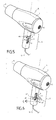
- the figure 4 illustrates another variant embodiment of the invention according to which the first lever 4 comprises means 35 for selecting an operating mode of the electrical apparatus A.
- These selection means 35 comprise, according to this example, a rotary switch 36 whose housing is secured to the first lever at its distal end 8 '.
- the rotary switch 36 comprises an operating wheel 37 which is accessible at the support back 15 of the first lever 4.
- the locking means 40 may be a half-ring 41 sliding on and along a portion of the levers 4 and 5. The slide slides in the direction of the levers indicated by the arrows illustrated.
- the locking means 40 may alternatively be a metal wire in the form of a folded U 42 and pivoting about the axis ⁇ according to the arrows shown. The U comes to rest against the body of the handle and to lock against two lateral studs 43 arranged on each side of the handle Z. As illustrated in FIG.
- the locking means 40 may be a slider 44 which is actuated in translation by the user along a corridor 45. When the user actuates the cursor downward, he crushes the lever so as to actuate the electric switch. If this slider is left in the up position, the lever is in the locked position.
Abstract
Description
La présente invention concerne le domaine technique des appareils électriques à main utilisés pour les soins de la personne tels que par exemple mais non exclusivement les sèche-cheveux ou brosses soufflantes. Il peut en effet concerner d'autres appareils de soin de la personne comme des lisseurs, des fers à boucler ou comme des épilateurs, des masseurs électriques.The present invention relates to the technical field of electrical hand appliances used for the care of the person such as for example but not exclusively hair dryers or blower brushes. It may affect other personal care appliances such as hair straighteners, curling irons or as epilators, electric massagers.
De tels appareils électriques à main de soin de la personne comprennent généralement un interrupteur bistable permettant d'allumer et d'éteindre l'appareil. Dans le cas d'un sèche-cheveux l'interrupteur bistable n'est pas toujours pratique dans la mesure où l'utilisateur peut être amené à déposer régulièrement le sèche-cheveux afin de pouvoir travailler à deux mains sur les cheveux en cours de coiffure. Or, soit le sèche-cheveux continue de fonctionner lorsqu'il est déposé, soit l'utilisateur doit manoeuvrer volontairement l'interrupteur pour arrêter le sèche-cheveux. Si l'utilisateur choisit de ne pas arrêter le sèche-cheveux alors le fonctionnement de ce dernier induit une consommation inutile d'énergie et le bruit de son fonctionnement persiste alors que l'appareil n'est pas utilisé. Si l'utilisateur choisit d'arrêter le sèche-cheveux à chaque fois qu'il le dépose cela lui impose une manoeuvre volontaire de l'interrupteur, mouvement qui par sa répétition induit une perte de temps.Such hand-held personal care appliances generally include a bistable switch to turn the appliance on and off. In the case of a hair dryer the bistable switch is not always practical to the extent that the user may be required to regularly deposit the hair dryer in order to work with both hands on the hair during hairdressing . Or, the hair dryer continues to work when it is deposited, or the user must deliberately operate the switch to stop the hair dryer. If the user chooses not to stop the hair dryer then the operation of the latter induces an unnecessary consumption of energy and the sound of its operation persists while the device is not used. If the user chooses to stop the hair dryer every time he drops it requires him a deliberate operation of the switch, which movement by its repetition causes a waste of time.
Afin de permettre un arrêt du fonctionnement du sèche-cheveux lorsqu'il est déposé et un redémarrage automatique lors de sa prise en main, un brevet
Il est donc apparu le besoin de moyens de commande qui permettent à la fois un démarrage et un arrêt automatique du fonctionnement de l'appareil électrique de soin corporel qu'ils équipent et qui présentent une sensibilité suffisante pour que quel que soit le mode de prise en main de l'appareil la fonction de commande automatique à «détection de la prise en main» soit assurée sans que l'utilisateur doive exercer une pression importante.It has therefore appeared the need for control means that allow both a start and an automatic shutdown of the operation of the electric body care device they equip and which have a sufficient sensitivity so that whatever the mode of taking in the hand of the device the function of automatic control "detection of grip" is ensured without the user must exert significant pressure.
Afin d'atteindre cet objectif, l'invention concerne un appareil électrique à main de soin de la personne comprenant :
- des moyens de préhension allongés offrant une zone de prise en main pour un utilisateur,
- des moyens de commande du fonctionnement de l'appareil comprenant un premier levier de commande allongé qui s'étend selon une direction parallèle à l'axe longitudinal des moyens de préhension, qui est accessible dans la zone de prise en main et qui est mobile en rotation par rapport aux moyens de préhension selon un axe de rotation situé à proximité d'une extrémité, dite proximale, du premier levier de manoeuvre ou de commande.
- elongate gripping means providing a grip area for a user,
- means for controlling the operation of the apparatus comprising a first elongate control lever which extends in a direction parallel to the longitudinal axis of the gripping means, which is accessible in the grip zone and which is movable in rotation relative to the gripping means according to a axis of rotation located near a so-called proximal end of the first operating lever or control.
Selon l'invention cet appareil électrique à main de soin de la personne est caractérisé en ce que les moyens de commande comprennent un deuxième levier de commande allongé qui s'étend parallèlement au premier levier de commande, qui est accessible dans la zone de prise en main et qui est mobile en rotation par rapport aux moyens de préhension selon un axe de rotation situé à proximité d'une extrémité, dite proximale, du deuxième levier de manoeuvre ou de commande, l'extrémité proximale du deuxième levier étant située à l'opposé de l'extrémité proximale du premier levier et l'axe de rotation du deuxième levier étant sensiblement parallèle à celui du premier levier.According to the invention, this electric hand-held personal care device is characterized in that the control means comprise a second elongated control lever which extends parallel to the first control lever, which is accessible in the engagement zone. hand and which is rotatable relative to the gripping means along an axis of rotation located near a so-called proximal end of the second operating or control lever, the proximal end of the second lever being located at the opposite of the proximal end of the first lever and the axis of rotation of the second lever being substantially parallel to that of the first lever.
La mise en oeuvre de deux leviers de commande qui se trouvent tête-bêche permet d'obtenir une grande sensibilité des moyens de commande quel que soit la configuration de prise en main dans la mesure où l'utilisateur aura toujours une partie de sa main qui presse sur un levier à distance de son axe de rotation et donc bénéficie d'une démultiplication suffisante pour agir sur l'organe des moyens de commande faisant office de contacteur ou d'interrupteur.The implementation of two control levers that are located head to tail makes it possible to obtain a great sensitivity of the control means whatever the configuration of grip in that the user will always have a part of his hand that press on a lever at a distance from its axis of rotation and therefore has sufficient gearing to act on the body of the control means acting as contactor or switch.
Selon l'invention, les leviers de commande ne sont pas nécessairement situés côte à côte et peuvent être par exemple situés sur deux faces opposées des moyens de préhension. Toutefois, selon une forme de réalisation de l'invention visant à faciliter la mise en oeuvre des moyens de commande, les deux leviers sont situés d'un même côté des moyens de préhension.According to the invention, the control levers are not necessarily located side by side and may for example be located on two opposite faces of the gripping means. However, according to one embodiment of the invention to facilitate the implementation of the control means, the two levers are located on the same side of the gripping means.
Selon une variante de cette forme de réalisation, les deux leviers sont adjacents.According to a variant of this embodiment, the two levers are adjacent.
Selon l'invention l'appareil électrique à main de soin de la personne peut être conçu pour permettre différents types de soins. Dans une application préférée mais non exclusive, l'appareil électrique à main de soin de la personne selon l'invention forme un sèche-cheveux comprenant un corps tubulaire allongé qui comprend, à l'avant, une sortie d'air et, à l'arrière, une entrée d'air et qui est équipé d'une poignée latérale formant les moyens de préhension. Dans le cadre de cette application préférée, les leviers de commande sont placés sur une face de la poignée orientée vers l'arrière.According to the invention the hand-held personal care appliance can be designed to allow different types of care. In a preferred but not exclusive application, the electric hand care device of the person according to the invention forms a hair dryer comprising an elongated tubular body which comprises, at the front, an air outlet and, at the rear, an air inlet and which is equipped with a lateral handle forming the gripping means. As part of this preferred application, the control levers are placed on one side of the handle facing backward.
Selon une caractéristique de l'invention, chaque levier comprend un dos d'appui pour la main d'un utilisateur, ce dos d'appui présentant une forme arquée convexe dans le sens de la longueur du levier correspondant.According to a characteristic of the invention, each lever comprises a support back for the hand of a user, this back having a convex arcuate shape in the direction of the length of the corresponding lever.
Dans le cadre de cette caractéristique et selon une variante de l'invention, la partie de chaque dos d'appui située entre le milieu et l'extrémité distale, opposée à l'extrémité proximale, s'étend plus en saillie des moyens de préhension que la partie du dos située à proximité de l'extrémité proximale du levier correspondant. Cette variante permet de privilégier l'appui sur la zone de chaque levier offrant la plus grande démultiplication de la pression exercée par les doigts de l'utilisateur.In the context of this feature and according to a variant of the invention, the portion of each support back located between the middle and the distal end, opposite to the proximal end, extends more protruding from the gripping means the part of the back located near the proximal end of the corresponding lever. This variant makes it possible to favor the support on the zone of each lever offering the greatest reduction in the pressure exerted by the fingers of the user.
Selon une autre caractéristique de l'invention, les moyens de commande sont adaptés pour assurer le fonctionnement de l'appareil en cas de pression sur l'un ou l'autre des leviers de commande. Ainsi, il n'est pas nécessaire que les deux leviers soient enfoncés pour assurer le fonctionnement de l'appareil ce qui garantit son confort d'utilisation.According to another characteristic of the invention, the control means are adapted to ensure the operation of the apparatus in the event of pressure on one or the other of the control levers. Thus, it is not necessary that the two levers are depressed to ensure the operation of the device which ensures its comfort of use.
Selon une variante de cette caractéristique, les deux leviers agissent sur un même organe de commande.According to a variant of this characteristic, the two levers act on the same control member.
Dans le cadre de cette variante, les deux leviers de commande peuvent posséder une même longueur, chaque levier de commande comprenant alors dans une région centrale un doigt de manoeuvre de l'organe de commande.In the context of this variant, the two control levers may have the same length, each control lever then comprising in a central region a control finger of the control member.
Selon une caractéristique de l'invention visant à permettre un fonctionnement de l'appareil électrique à main de soin de la personne selon différents modes, l'un des leviers au moins comprend des moyens de sélection d'un mode de fonctionnement de l'appareil électrique.According to a feature of the invention for enabling operation of the hand-held personal care device according to different modes, one of the levers at least includes means for selecting an operating mode of the electrical apparatus.
Selon une autre caractéristique de l'invention visant à permettre une réalisation des leviers et de leur articulation à moindre coût, les moyens de préhension comprennent au moins une coque en matière plastique et les leviers font partie intégrante de la coque en étant chacun liés à la coque par une zone de moindre épaisseur formant l'axe de rotation du levier correspondant.According to another characteristic of the invention aimed at enabling the levers and their articulation to be produced at a lower cost, the gripping means comprise at least one plastic shell and the levers are an integral part of the shell while being each connected to the shell. shell by a zone of lesser thickness forming the axis of rotation of the corresponding lever.
Selon une autre caractéristique de l'invention, l'appareil électrique peut comporter des moyens de verrouillage activables qui, en mode activé, sont actifs et verrouillent les deux leviers des moyens de commande en fonctionnement de l'appareil, et qui, en mode désactivé, sont inactifs sur les deux leviers des moyens de commande. Ceci permet, lorsque l'utilisateur le souhaite, de commander en fonctionnement l'appareil sans devoir appuyer sur les leviers de commande.According to another characteristic of the invention, the electrical apparatus may comprise activatable locking means which, in activated mode, are active and lock the two levers of the operating control means of the apparatus, and which, in deactivated mode, are inactive on the two levers of the control means. This allows, when the user wishes, to control the device in operation without having to press the control levers.
Bien entendu, les différentes caractéristiques, variantes et formes de réalisation de l'invention peuvent être associées les unes avec les autres selon diverses combinaisons dans la mesure où elles ne sont pas incompatibles ou exclusives les unes des autres.Of course, the various features, variations and embodiments of the invention may be associated with each other in various combinations to the extent that they are not incompatible or exclusive of each other.
Par ailleurs, diverses autres caractéristiques de l'invention ressortent de la description annexée effectuée en référence aux dessins qui illustrent des formes non limitatives de réalisation des moyens de commande d'un appareil de soin de la personne conforme à l'invention.
- La
figure 1 est une perspective schématique d'un appareil électrique de soin de la personne selon l'invention formant un sèche-cheveux. - La
figure 2 est une coupe longitudinale schématique montrant une première forme de réalisation des moyens de commande à deux leviers tête-bêche mise en oeuvre sur l'appareil électrique de soin de la personne illustréfigure 1 . - La
figure 3 est une coupe longitudinale schématique montrant une deuxième forme de réalisation des moyens de commande à deux leviers tête-bêche selon l'invention. - La
figure 4 est une coupe schématique analogue à lafigure 2 montrant l'un des deux leviers équipé d'une roue de sélection d'un mode de fonctionnement de l'appareil électrique de soin de la personne selon l'invention. - Les
figures 5, 6 et7 sont une perspective schématique de trois modes alternatifs de réalisation d'un moyen de verrouillage des leviers selon l'invention.
- The
figure 1 is a schematic perspective of an electric personal care apparatus according to the invention forming a hair dryer. - The
figure 2 is a schematic longitudinal section showing a first embodiment of the control means with two levers head-to-tail implementation on the electric appliance of the person shownfigure 1 . - The
figure 3 is a schematic longitudinal section showing a second embodiment of the control means with two levers head-to-tail according to the invention. - The
figure 4 is a schematic section similar tofigure 2 showing one of the two levers equipped with a selection wheel of a mode of operation of the personal care appliance according to the invention. - The
Figures 5, 6 and7 are a schematic perspective of three alternative embodiments of lever locking means according to the invention.
Un appareil électrique à main de soin de la personne A peut par exemple former un sèche-cheveux tel qu'illustré à la
Le pilotage du fonctionnement de l'appareil A est assuré par des moyens de commande 3 qui sont disposés dans la poignée 2 et sont accessibles en partie au niveau d'une zone de prise en main Z et, selon l'exemple, au niveau d'une face de la poignée 2 orientée vers l'arrière de l'appareil A.The control of the operation of the apparatus A is provided by
Selon l'invention et comme le montre plus particulièrement la
Chaque levier 4, 5 est mobile en rotation par rapport aux moyens de préhension 2 selon un axe de rotation respectivement 6 et 7 perpendiculaire à un plan axial passant par l'axe longitudinal L. Les axes de rotation 6 et 7 sont parallèles entre eux de sorte que les leviers 4 et 5 sont mobiles en rotation dans deux plans parallèles. Chaque axe de rotation, 6 respectivement 7, est en outre situé au niveau d'une extrémité dite proximale, 8 respectivement 9, du levier de manoeuvre correspondant, 4 respectivement 5. Les extrémités proximales 8 et 9 des leviers 4 et 5 sont situées à l'opposé l'une de l'autre. Ainsi, l'axe de rotation 6 du premier levier 4 est situé du côté de l'extrémité proximale 9' du deuxième levier 5 tandis que l'axe de rotation 7 du deuxième levier 5 est situé du côté de l'extrémité proximale 8' du premier levier 4. La disposition des leviers 4 et 5 l'un par rapport à l'autre peut donc être qualifiée de tête bêche.Each
Chaque levier comprend un dos 15 qui s'étend en saillie à l'extérieur des moyens de préhension, dans le cas présent, de la poignée 2 et qui offre une surface d'appui pour la main ou les doigts d'un utilisateur. Selon l'exemple illustré chaque dos d'appui 15 présente une forme arquée convexe dans le sens de la longueur du levier correspondant.Each lever comprises a back 15 which protrudes outside the gripping means, in this case, the
Les moyens de commande 3 sont adaptés pour assurer le fonctionnement de l'appareil A en cas de pression sur l'un ou l'autre des leviers de commande 4, 5. Selon l'exemple illustré ce mode de fonctionnement est atteint au moyen de deux doigts de manoeuvre 16 et 17 qui équipent respectivement le premier 4 et le deuxième levier 5, au niveau de leur face opposée à leur dos d'appui 15. Chaque doigt de manoeuvre est situé dans une région centrale du levier correspondant et agit sur le même bras 18 d'un organe de commande 19, ici un interrupteur commandant l'alimentation du moteur électrique du sèche-cheveux A.The control means 3 are adapted to ensure the operation of the apparatus A in the event of pressure on one or the other of the control levers 4, 5. According to the illustrated example, this mode of operation is achieved by means of two operating
Les moyens de commande 3 ainsi formés fonctionnent de la manière suivante. Lorsqu'un utilisateur saisit la poignée 2 certains au moins de ses doigts viennent presser sur le dos d'appui 15 d'au moins un des leviers 4 ou 5 voire les dos d'appui 15 des deux leviers 4 et 5 qui pivotent alors dans le sens de la flèche F5 pour ce qui concerne le deuxième levier 5 et dans le sens de la flèche F4 pour ce qui concerne le premier levier 4. Cette rotation entraîne un déplacement des doigts de manoeuvre 16 et 17 correspondant qui pressent le bras 18 entraînant la fermeture du circuit d'alimentation commandée par l'organe 19. Il doit être noté que la position centrale des doigts de manoeuvre 16 et 17 leur permet d'agir sur le même organe 19.The control means 3 thus formed operate in the following manner. When a user grasps the
Selon l'exemple illustré, la partie 20, du dos d'appui 15 du premier levier 4, située entre la région centrale et l'extrémité distale 8' dudit premier levier 4 s'étend plus en saillie de la poignée 2 formant les moyens de préhension que la partie 21 du dos 15 du premier levier 4 située à proximité de l'extrémité proximale 8. De la même manière, la partie 22, du dos d'appui 15 du deuxième levier 5, située entre la région centrale et l'extrémité distale 9' dudit deuxième levier 5 s'étend plus en saillie de la poignée 2 formant les moyens de préhension que la partie 23 du dos 15 du deuxième levier 5 située à proximité de l'extrémité proximale 9.According to the illustrated example, the
Ce mode de réalisation permet d'offrir une plus grande sensibilité au système de commande formé des deux leviers 4 et 5. En effet cela permet d'éviter, lorsque les doigts de l'utilisateur sont placés en regard d'un axe de rotation, que la partie proximale du levier articulé par ledit axe, fasse obstacle au déplacement de l'autre levier.This embodiment makes it possible to offer a greater sensitivity to the control system formed by the two
Selon l'invention, les axes de rotation 6 et 7 peuvent être réalisés de toute manière appropriée. Les axes de rotation 6 et 7 peuvent, par exemple, chacun faire partie intégrante du levier correspondant pour venir s'articuler dans une chape aménagée dans les moyens de préhension. Les axes de rotation 6 et 7 peuvent également être formés chacun par un arbre qui est engagé dans un alésage du levier correspondant.According to the invention, the axes of
Selon une forme de réalisation de l'invention, illustrée
La
L'utilisateur a la possibilité, s'il le souhaite, de verrouiller la commande de l'appareil sans devoir appuyer sur le système de commande à double levier 4 et 5 en permanence. Les
Bien entendu, diverses autres modifications peuvent être apportées à l'appareil électrique à main de soin de la personne selon l'invention dans le cadre des revendications annexées.Of course, various other modifications may be made to the hand-held personal care appliance according to the invention within the scope of the appended claims.
Claims (12)
caractérisé en ce que les moyens de commande (3) comprennent un deuxième levier de commande allongé (5) qui s'étend parallèlement au premier levier de commande (4), qui est accessible dans la zone de prise en main et qui est mobile en rotation par rapport aux moyens de préhension (2) selon un axe de rotation (7) situé à proximité d'une extrémité, dite proximale, (9) du deuxième levier de manoeuvre (5), l'extrémité proximale (9) du deuxième levier (5) étant située à l'opposé de l'extrémité proximale (8) du premier levier (4) et l'axe de rotation (7) du deuxième levier (5) étant sensiblement parallèle à celui (6) du premier levier (4).
characterized in that the control means (3) comprises a second elongate control lever (5) which extends parallel to the first control lever (4), which is accessible in the grip zone and which is movable in rotation relative to the gripping means (2) along an axis of rotation (7) located near a so-called proximal end (9) of the second operating lever (5), the proximal end (9) of the second lever (5) being located opposite the proximal end (8) of the first lever (4) and the axis of rotation (7) of the second lever (5) being substantially parallel to that (6) of the first lever (4).
Applications Claiming Priority (1)
| Application Number | Priority Date | Filing Date | Title |
|---|---|---|---|
| FR1154016A FR2974982B1 (en) | 2011-05-10 | 2011-05-10 | ELECTRIC HAND CARE APPARATUS OF THE PERSON WITH A DOUBLE CONTROL LEVER |
Publications (2)
| Publication Number | Publication Date |
|---|---|
| EP2522245A1 true EP2522245A1 (en) | 2012-11-14 |
| EP2522245B1 EP2522245B1 (en) | 2014-07-02 |
Family
ID=45998200
Family Applications (1)
| Application Number | Title | Priority Date | Filing Date |
|---|---|---|---|
| EP20120166322 Active EP2522245B1 (en) | 2011-05-10 | 2012-05-02 | Handheld electrical apparatus for personal care with dual control lever |
Country Status (4)
| Country | Link |
|---|---|
| EP (1) | EP2522245B1 (en) |
| CN (1) | CN202820037U (en) |
| ES (1) | ES2508740T3 (en) |
| FR (1) | FR2974982B1 (en) |
Families Citing this family (1)
| Publication number | Priority date | Publication date | Assignee | Title |
|---|---|---|---|---|
| CN109338967A (en) * | 2018-11-28 | 2019-02-15 | 浙江动新能源动力科技股份有限公司 | A kind of axial-flow type hair dryer |
Citations (3)
| Publication number | Priority date | Publication date | Assignee | Title |
|---|---|---|---|---|
| FR1398769A (en) * | 1962-12-15 | 1965-05-14 | Bosch Gmbh Robert | Actuating device for connector of incorporated electrical devices |
| US4683369A (en) | 1986-02-05 | 1987-07-28 | John Zink Company | Hand held electric hair dryer |
| US5195164A (en) * | 1990-05-17 | 1993-03-16 | Lambert William S | Electric heater/blowers with selectively-locked output variable heat and blower controls |
-
2011
- 2011-05-10 FR FR1154016A patent/FR2974982B1/en not_active Expired - Fee Related
-
2012
- 2012-05-02 ES ES12166322.3T patent/ES2508740T3/en active Active
- 2012-05-02 EP EP20120166322 patent/EP2522245B1/en active Active
- 2012-05-03 CN CN 201220196082 patent/CN202820037U/en not_active Expired - Lifetime
Patent Citations (3)
| Publication number | Priority date | Publication date | Assignee | Title |
|---|---|---|---|---|
| FR1398769A (en) * | 1962-12-15 | 1965-05-14 | Bosch Gmbh Robert | Actuating device for connector of incorporated electrical devices |
| US4683369A (en) | 1986-02-05 | 1987-07-28 | John Zink Company | Hand held electric hair dryer |
| US5195164A (en) * | 1990-05-17 | 1993-03-16 | Lambert William S | Electric heater/blowers with selectively-locked output variable heat and blower controls |
Also Published As
| Publication number | Publication date |
|---|---|
| FR2974982B1 (en) | 2013-06-14 |
| CN202820037U (en) | 2013-03-27 |
| EP2522245B1 (en) | 2014-07-02 |
| FR2974982A1 (en) | 2012-11-16 |
| ES2508740T3 (en) | 2014-10-16 |
Similar Documents
| Publication | Publication Date | Title |
|---|---|---|
| EP2335533B1 (en) | Household cooking appliance designed to be held in the hand provided with a specific control device | |
| FR2870764A3 (en) | HAND-HELD ELECTRIC TOOL WITH REMOVABLE HANDLE | |
| EP2198736B1 (en) | Hairdressing device with jaws for setting the hair | |
| FR2897286A3 (en) | CIRCUIT CLOSURE / OPENING CONTROL MECHANISM OF AN ELECTRIC RATCHET KEY. | |
| FR2913570A1 (en) | HAIRSTYLING APPARATUS | |
| FR2913571A1 (en) | HAIRSTYLING APPARATUS | |
| EP1215976B1 (en) | Hand-held electrical appliance such as a hair drier provided with position adjustable control members | |
| EP1567029B1 (en) | Hair dryer | |
| EP2522245B1 (en) | Handheld electrical apparatus for personal care with dual control lever | |
| EP3841913A1 (en) | Hair-styling appliance with rotary multifunctional accessory lockable in position relative to the handle | |
| US20090211590A1 (en) | Electronic nail filer | |
| EP2337046A1 (en) | Device for controlling a switch of a household appliance | |
| EP3165139B1 (en) | Household food-preparation appliance comprising a drive device of a rotary work tool provided with a braking system | |
| FR2883651A1 (en) | ROTARY BUTTON AND CONTROL PANEL, IN PARTICULAR FOR A VENTILATION, HEATING AND / OR AIR CONDITIONING INSTALLATION | |
| FR2882625A1 (en) | Motorized hedge trimmer for shrubs, has rear part with fixed interposed handle and end handle, where end handle is inclined at specific angle relative to longitudinal axis, and control units of both handles move in direction normal to axis | |
| FR2994639A1 (en) | HAIRSTYLING APPARATUS WITH OPTIMIZED ERGONOMICS | |
| EP3845091A1 (en) | Improved hair-styling appliance forming an oscillating blower brush | |
| FR2811213A1 (en) | HOUSEHOLD APPLIANCE FOR CULINARY PREPARATION PROVIDED TO BE HAND HELD ACCORDING TO DIFFERENT POSITIONS | |
| CA2379390A1 (en) | Device for unlocking a compartment of an opening mechanism | |
| EP2606786B1 (en) | Cooking appliance with safety for the presence of heating plates | |
| EP1569816B1 (en) | Seat comprising an operating handle | |
| EP0609161B1 (en) | Control for combined microwave and grill oven | |
| WO2020260140A1 (en) | Motorised housing for a household appliance configured to be hand-held | |
| EP4355167A1 (en) | Hairstyling appliance having an improved oscillating blower-brush mode | |
| WO2022263775A1 (en) | Hairstyling appliance having mutliple blowing modes, comprising a push-push control mechanism |
Legal Events
| Date | Code | Title | Description |
|---|---|---|---|
| PUAI | Public reference made under article 153(3) epc to a published international application that has entered the european phase |
Free format text: ORIGINAL CODE: 0009012 |
|
| AK | Designated contracting states |
Kind code of ref document: A1 Designated state(s): AL AT BE BG CH CY CZ DE DK EE ES FI FR GB GR HR HU IE IS IT LI LT LU LV MC MK MT NL NO PL PT RO RS SE SI SK SM TR |
|
| AX | Request for extension of the european patent |
Extension state: BA ME |
|
| 17P | Request for examination filed |
Effective date: 20130426 |
|
| GRAP | Despatch of communication of intention to grant a patent |
Free format text: ORIGINAL CODE: EPIDOSNIGR1 |
|
| INTG | Intention to grant announced |
Effective date: 20140129 |
|
| GRAS | Grant fee paid |
Free format text: ORIGINAL CODE: EPIDOSNIGR3 |
|
| GRAA | (expected) grant |
Free format text: ORIGINAL CODE: 0009210 |
|
| AK | Designated contracting states |
Kind code of ref document: B1 Designated state(s): AL AT BE BG CH CY CZ DE DK EE ES FI FR GB GR HR HU IE IS IT LI LT LU LV MC MK MT NL NO PL PT RO RS SE SI SK SM TR |
|
| REG | Reference to a national code |
Ref country code: GB Ref legal event code: FG4D Free format text: NOT ENGLISH |
|
| REG | Reference to a national code |
Ref country code: CH Ref legal event code: EP Ref country code: AT Ref legal event code: REF Ref document number: 675398 Country of ref document: AT Kind code of ref document: T Effective date: 20140715 |
|
| REG | Reference to a national code |
Ref country code: IE Ref legal event code: FG4D Free format text: LANGUAGE OF EP DOCUMENT: FRENCH |
|
| REG | Reference to a national code |
Ref country code: DE Ref legal event code: R096 Ref document number: 602012002276 Country of ref document: DE Effective date: 20140814 |
|
| REG | Reference to a national code |
Ref country code: ES Ref legal event code: FG2A Ref document number: 2508740 Country of ref document: ES Kind code of ref document: T3 Effective date: 20141016 |
|
| REG | Reference to a national code |
Ref country code: AT Ref legal event code: MK05 Ref document number: 675398 Country of ref document: AT Kind code of ref document: T Effective date: 20140702 |
|
| REG | Reference to a national code |
Ref country code: NL Ref legal event code: VDEP Effective date: 20140702 |
|
| REG | Reference to a national code |
Ref country code: LT Ref legal event code: MG4D |
|
| PG25 | Lapsed in a contracting state [announced via postgrant information from national office to epo] |
Ref country code: SE Free format text: LAPSE BECAUSE OF FAILURE TO SUBMIT A TRANSLATION OF THE DESCRIPTION OR TO PAY THE FEE WITHIN THE PRESCRIBED TIME-LIMIT Effective date: 20140702 Ref country code: GR Free format text: LAPSE BECAUSE OF FAILURE TO SUBMIT A TRANSLATION OF THE DESCRIPTION OR TO PAY THE FEE WITHIN THE PRESCRIBED TIME-LIMIT Effective date: 20141003 Ref country code: CZ Free format text: LAPSE BECAUSE OF FAILURE TO SUBMIT A TRANSLATION OF THE DESCRIPTION OR TO PAY THE FEE WITHIN THE PRESCRIBED TIME-LIMIT Effective date: 20140702 Ref country code: FI Free format text: LAPSE BECAUSE OF FAILURE TO SUBMIT A TRANSLATION OF THE DESCRIPTION OR TO PAY THE FEE WITHIN THE PRESCRIBED TIME-LIMIT Effective date: 20140702 Ref country code: NO Free format text: LAPSE BECAUSE OF FAILURE TO SUBMIT A TRANSLATION OF THE DESCRIPTION OR TO PAY THE FEE WITHIN THE PRESCRIBED TIME-LIMIT Effective date: 20141002 Ref country code: BG Free format text: LAPSE BECAUSE OF FAILURE TO SUBMIT A TRANSLATION OF THE DESCRIPTION OR TO PAY THE FEE WITHIN THE PRESCRIBED TIME-LIMIT Effective date: 20141002 Ref country code: LT Free format text: LAPSE BECAUSE OF FAILURE TO SUBMIT A TRANSLATION OF THE DESCRIPTION OR TO PAY THE FEE WITHIN THE PRESCRIBED TIME-LIMIT Effective date: 20140702 Ref country code: PT Free format text: LAPSE BECAUSE OF FAILURE TO SUBMIT A TRANSLATION OF THE DESCRIPTION OR TO PAY THE FEE WITHIN THE PRESCRIBED TIME-LIMIT Effective date: 20141103 |
|
| PG25 | Lapsed in a contracting state [announced via postgrant information from national office to epo] |
Ref country code: CY Free format text: LAPSE BECAUSE OF FAILURE TO SUBMIT A TRANSLATION OF THE DESCRIPTION OR TO PAY THE FEE WITHIN THE PRESCRIBED TIME-LIMIT Effective date: 20140702 Ref country code: LV Free format text: LAPSE BECAUSE OF FAILURE TO SUBMIT A TRANSLATION OF THE DESCRIPTION OR TO PAY THE FEE WITHIN THE PRESCRIBED TIME-LIMIT Effective date: 20140702 Ref country code: AT Free format text: LAPSE BECAUSE OF FAILURE TO SUBMIT A TRANSLATION OF THE DESCRIPTION OR TO PAY THE FEE WITHIN THE PRESCRIBED TIME-LIMIT Effective date: 20140702 Ref country code: IS Free format text: LAPSE BECAUSE OF FAILURE TO SUBMIT A TRANSLATION OF THE DESCRIPTION OR TO PAY THE FEE WITHIN THE PRESCRIBED TIME-LIMIT Effective date: 20141102 Ref country code: RS Free format text: LAPSE BECAUSE OF FAILURE TO SUBMIT A TRANSLATION OF THE DESCRIPTION OR TO PAY THE FEE WITHIN THE PRESCRIBED TIME-LIMIT Effective date: 20140702 Ref country code: HR Free format text: LAPSE BECAUSE OF FAILURE TO SUBMIT A TRANSLATION OF THE DESCRIPTION OR TO PAY THE FEE WITHIN THE PRESCRIBED TIME-LIMIT Effective date: 20140702 Ref country code: PL Free format text: LAPSE BECAUSE OF FAILURE TO SUBMIT A TRANSLATION OF THE DESCRIPTION OR TO PAY THE FEE WITHIN THE PRESCRIBED TIME-LIMIT Effective date: 20140702 Ref country code: NL Free format text: LAPSE BECAUSE OF FAILURE TO SUBMIT A TRANSLATION OF THE DESCRIPTION OR TO PAY THE FEE WITHIN THE PRESCRIBED TIME-LIMIT Effective date: 20140702 |
|
| REG | Reference to a national code |
Ref country code: DE Ref legal event code: R097 Ref document number: 602012002276 Country of ref document: DE |
|
| PG25 | Lapsed in a contracting state [announced via postgrant information from national office to epo] |
Ref country code: DK Free format text: LAPSE BECAUSE OF FAILURE TO SUBMIT A TRANSLATION OF THE DESCRIPTION OR TO PAY THE FEE WITHIN THE PRESCRIBED TIME-LIMIT Effective date: 20140702 Ref country code: RO Free format text: LAPSE BECAUSE OF FAILURE TO SUBMIT A TRANSLATION OF THE DESCRIPTION OR TO PAY THE FEE WITHIN THE PRESCRIBED TIME-LIMIT Effective date: 20140702 Ref country code: SK Free format text: LAPSE BECAUSE OF FAILURE TO SUBMIT A TRANSLATION OF THE DESCRIPTION OR TO PAY THE FEE WITHIN THE PRESCRIBED TIME-LIMIT Effective date: 20140702 Ref country code: EE Free format text: LAPSE BECAUSE OF FAILURE TO SUBMIT A TRANSLATION OF THE DESCRIPTION OR TO PAY THE FEE WITHIN THE PRESCRIBED TIME-LIMIT Effective date: 20140702 |
|
| PLBE | No opposition filed within time limit |
Free format text: ORIGINAL CODE: 0009261 |
|
| STAA | Information on the status of an ep patent application or granted ep patent |
Free format text: STATUS: NO OPPOSITION FILED WITHIN TIME LIMIT |
|
| 26N | No opposition filed |
Effective date: 20150407 |
|
| PG25 | Lapsed in a contracting state [announced via postgrant information from national office to epo] |
Ref country code: SI Free format text: LAPSE BECAUSE OF FAILURE TO SUBMIT A TRANSLATION OF THE DESCRIPTION OR TO PAY THE FEE WITHIN THE PRESCRIBED TIME-LIMIT Effective date: 20140702 |
|
| REG | Reference to a national code |
Ref country code: DE Ref legal event code: R119 Ref document number: 602012002276 Country of ref document: DE |
|
| REG | Reference to a national code |
Ref country code: CH Ref legal event code: PL |
|
| PG25 | Lapsed in a contracting state [announced via postgrant information from national office to epo] |
Ref country code: MC Free format text: LAPSE BECAUSE OF FAILURE TO SUBMIT A TRANSLATION OF THE DESCRIPTION OR TO PAY THE FEE WITHIN THE PRESCRIBED TIME-LIMIT Effective date: 20140702 Ref country code: LU Free format text: LAPSE BECAUSE OF FAILURE TO SUBMIT A TRANSLATION OF THE DESCRIPTION OR TO PAY THE FEE WITHIN THE PRESCRIBED TIME-LIMIT Effective date: 20150502 Ref country code: LI Free format text: LAPSE BECAUSE OF NON-PAYMENT OF DUE FEES Effective date: 20150531 Ref country code: CH Free format text: LAPSE BECAUSE OF NON-PAYMENT OF DUE FEES Effective date: 20150531 |
|
| REG | Reference to a national code |
Ref country code: IE Ref legal event code: MM4A |
|
| PG25 | Lapsed in a contracting state [announced via postgrant information from national office to epo] |
Ref country code: DE Free format text: LAPSE BECAUSE OF NON-PAYMENT OF DUE FEES Effective date: 20151201 Ref country code: IE Free format text: LAPSE BECAUSE OF NON-PAYMENT OF DUE FEES Effective date: 20150502 |
|
| REG | Reference to a national code |
Ref country code: FR Ref legal event code: PLFP Year of fee payment: 5 |
|
| REG | Reference to a national code |
Ref country code: ES Ref legal event code: FD2A Effective date: 20160624 |
|
| PG25 | Lapsed in a contracting state [announced via postgrant information from national office to epo] |
Ref country code: ES Free format text: LAPSE BECAUSE OF NON-PAYMENT OF DUE FEES Effective date: 20150503 |
|
| PGFP | Annual fee paid to national office [announced via postgrant information from national office to epo] |
Ref country code: GB Payment date: 20160518 Year of fee payment: 5 |
|
| PG25 | Lapsed in a contracting state [announced via postgrant information from national office to epo] |
Ref country code: MT Free format text: LAPSE BECAUSE OF FAILURE TO SUBMIT A TRANSLATION OF THE DESCRIPTION OR TO PAY THE FEE WITHIN THE PRESCRIBED TIME-LIMIT Effective date: 20140702 |
|
| REG | Reference to a national code |
Ref country code: FR Ref legal event code: PLFP Year of fee payment: 6 |
|
| PG25 | Lapsed in a contracting state [announced via postgrant information from national office to epo] |
Ref country code: SM Free format text: LAPSE BECAUSE OF FAILURE TO SUBMIT A TRANSLATION OF THE DESCRIPTION OR TO PAY THE FEE WITHIN THE PRESCRIBED TIME-LIMIT Effective date: 20140702 Ref country code: HU Free format text: LAPSE BECAUSE OF FAILURE TO SUBMIT A TRANSLATION OF THE DESCRIPTION OR TO PAY THE FEE WITHIN THE PRESCRIBED TIME-LIMIT; INVALID AB INITIO Effective date: 20120502 |
|
| REG | Reference to a national code |
Ref country code: FR Ref legal event code: CA Effective date: 20170518 |
|
| PG25 | Lapsed in a contracting state [announced via postgrant information from national office to epo] |
Ref country code: BE Free format text: LAPSE BECAUSE OF NON-PAYMENT OF DUE FEES Effective date: 20150531 |
|
| PG25 | Lapsed in a contracting state [announced via postgrant information from national office to epo] |
Ref country code: TR Free format text: LAPSE BECAUSE OF FAILURE TO SUBMIT A TRANSLATION OF THE DESCRIPTION OR TO PAY THE FEE WITHIN THE PRESCRIBED TIME-LIMIT Effective date: 20140702 |
|
| GBPC | Gb: european patent ceased through non-payment of renewal fee |
Effective date: 20170502 |
|
| PG25 | Lapsed in a contracting state [announced via postgrant information from national office to epo] |
Ref country code: GB Free format text: LAPSE BECAUSE OF NON-PAYMENT OF DUE FEES Effective date: 20170502 |
|
| REG | Reference to a national code |
Ref country code: FR Ref legal event code: PLFP Year of fee payment: 7 |
|
| PG25 | Lapsed in a contracting state [announced via postgrant information from national office to epo] |
Ref country code: MK Free format text: LAPSE BECAUSE OF FAILURE TO SUBMIT A TRANSLATION OF THE DESCRIPTION OR TO PAY THE FEE WITHIN THE PRESCRIBED TIME-LIMIT Effective date: 20140702 |
|
| PG25 | Lapsed in a contracting state [announced via postgrant information from national office to epo] |
Ref country code: AL Free format text: LAPSE BECAUSE OF FAILURE TO SUBMIT A TRANSLATION OF THE DESCRIPTION OR TO PAY THE FEE WITHIN THE PRESCRIBED TIME-LIMIT Effective date: 20140702 |
|
| PGFP | Annual fee paid to national office [announced via postgrant information from national office to epo] |
Ref country code: IT Payment date: 20210512 Year of fee payment: 10 |
|
| P01 | Opt-out of the competence of the unified patent court (upc) registered |
Effective date: 20230517 |
|
| PG25 | Lapsed in a contracting state [announced via postgrant information from national office to epo] |
Ref country code: IT Free format text: LAPSE BECAUSE OF NON-PAYMENT OF DUE FEES Effective date: 20220502 |
|
| PGFP | Annual fee paid to national office [announced via postgrant information from national office to epo] |
Ref country code: FR Payment date: 20230523 Year of fee payment: 12 |