EP2520919A2 - Device and Method for Measuring Pressure on Wind Turbine Components - Google Patents
Device and Method for Measuring Pressure on Wind Turbine Components Download PDFInfo
- Publication number
- EP2520919A2 EP2520919A2 EP12166369A EP12166369A EP2520919A2 EP 2520919 A2 EP2520919 A2 EP 2520919A2 EP 12166369 A EP12166369 A EP 12166369A EP 12166369 A EP12166369 A EP 12166369A EP 2520919 A2 EP2520919 A2 EP 2520919A2
- Authority
- EP
- European Patent Office
- Prior art keywords
- layer
- pressure
- pressure sensor
- sensors
- sensor
- Prior art date
- Legal status (The legal status is an assumption and is not a legal conclusion. Google has not performed a legal analysis and makes no representation as to the accuracy of the status listed.)
- Granted
Links
Images


Classifications
-
- G—PHYSICS
- G01—MEASURING; TESTING
- G01M—TESTING STATIC OR DYNAMIC BALANCE OF MACHINES OR STRUCTURES; TESTING OF STRUCTURES OR APPARATUS, NOT OTHERWISE PROVIDED FOR
- G01M9/00—Aerodynamic testing; Arrangements in or on wind tunnels
- G01M9/06—Measuring arrangements specially adapted for aerodynamic testing
- G01M9/065—Measuring arrangements specially adapted for aerodynamic testing dealing with flow
-
- G—PHYSICS
- G01—MEASURING; TESTING
- G01L—MEASURING FORCE, STRESS, TORQUE, WORK, MECHANICAL POWER, MECHANICAL EFFICIENCY, OR FLUID PRESSURE
- G01L15/00—Devices or apparatus for measuring two or more fluid pressure values simultaneously
Definitions
- the subject matter described herein relates generally to methods and systems for the pressure measurement on airfoils and hydrofoils, and more particularly, to methods and systems for the pressure measurement on wind turbine rotor blades.
- At least some known wind turbines include a tower and a nacelle mounted on the tower.
- a rotor is rotatably mounted to the nacelle and is coupled to a generator by a shaft.
- a plurality of blades extend from the rotor. The blades are oriented such that wind passing over the blades turns the rotor and rotates the shaft, thereby driving the generator to generate electricity.
- the pressure distribution around the profile of the same may be measured.
- a number of techniques are well known. Amongst others, it is known to drill small holes into the surface of the structure and to apply pressure tubes which are routed to a measurement system inside the structure. Further, the application of pitot tubes or pressure sensors on the surface of the profile of a foil or wing is also applied. If the pressure close to the surface of the structure shall be measured, pressure sensors are typically mounted in small holes in the surface, which allows for a measurement at face level.
- the surface of the rotor blade or airfoil is typically manipulated by drilling holes in which the sensors are placed.
- sensors may also be mounted to the aerodynamic face of the structure, e.g. via the use of adhesives, this can lead to an undesirable distortion of the airflow in the vicinity of the attached sensor and thus to biased or misleading measurement results.
- wires have to be installed. These are typically routed through the interior of the blade or wing, involving a significant amount of labor, which is time consuming and at least partially leads to changes in the structure of the blade or wing.
- the wires may also be installed on the surface of an airfoil or rotor blade, which requires less time and effort, but may contribute to a distortion of the airflow in the vicinity of the sensors, and thus to a degradation of the quality of the acquired data.
- a device for measuring air pressure on a wind turbine component includes at least one flexible layer having a first surface adapted for fixing the layer to a structure, and having a second surface having at least one recess; at least one pressure sensor, provided in the at least one recess; and at least two wires connected to the at least one pressure sensor for connecting the at least one pressure sensor to a signal receiving unit.
- a device for measuring fluid pressure includes at least one flexible layer having a first surface adapted for fixing the layer to a structure, and having a second surface having at least one opening; at least one pressure sensor; and at least one fluid channel connecting the at least one opening and the at least one pressure sensor.
- a method of measuring fluid pressure includes providing at least one flexible layer having a first surface and a second surface including at least an opening, and at least one pressure sensor in fluidal connection with a fluid in the vicinity of the at least one opening; fixing the at least one flexible layer to an outer surface of a structure; and acquiring pressure signals from the at least one pressure sensor.
- the embodiments described herein include a device for measuring fluid pressures around a structure without the need for making structural modifications to the structure. More specifically, the device allows for measuring an air pressure in the vicinity of wings, wind turbine rotor blades or other parts of wind turbines such as hubs or nacelle parts.
- blade is intended to be representative of any device that provides a reactive force when in motion relative to a surrounding fluid.
- wind turbine is intended to be representative of any device that generates rotational energy from wind energy, and more specifically, converts kinetic energy of wind into mechanical energy.
- wind generator is intended to be representative of any wind turbine that generates electrical power from rotational energy generated from wind energy, and more specifically, converts mechanical energy converted from kinetic energy of wind to electrical power.
- wind turbine component is intended to be representative of any part of a wind turbine, for instance, a rotor blade, a rotor hub, a nacelle, and a tower.
- FIG. 1 is a perspective view of an exemplary wind turbine 10.
- wind turbine 10 is a horizontal-axis wind turbine.
- wind turbine 10 may be a vertical-axis wind turbine.
- wind turbine 10 includes a tower 12 that extends from a support system 14, a nacelle 16 mounted on tower 12, and a rotor 18 that is coupled to nacelle 16.
- Rotor 18 includes a rotatable hub 20 and at least one rotor blade 22 coupled to and extending outward from hub 20.
- rotor 18 has three rotor blades 22.
- rotor 18 includes more or less than three rotor blades 22.
- tower 12 is fabricated from tubular steel to defme a cavity (not shown in Figure 1 ) between support system 14 and nacelle 16.
- tower 12 is any suitable type of tower having any suitable height.
- Rotor blades 22 are spaced about hub 20 to facilitate rotating rotor 18 to enable kinetic energy to be transferred from the wind into usable mechanical energy, and subsequently, electrical energy.
- Rotor blades 22 are mated to hub 20 by coupling a blade root portion 24 to hub 20 at a plurality of load transfer regions 26.
- Load transfer regions 26 have a hub load transfer region and a blade load transfer region (both not shown in Figure 1 ). Loads induced to rotor blades 22 are transferred to hub 20 via load transfer regions 26.
- rotor blades 22 have a length ranging from about 15 meters (m) to about 91 m.
- rotor blades 22 may have any suitable length that enables wind turbine 10 to function as described herein.
- other non-limiting examples of blade lengths include 10 m or less, 20 m, 37 m, or a length that is greater than 91 m.
- rotor 18 is rotated about an axis of rotation 30.
- rotor blades 22 are also subjected to various forces and moments. As such, rotor blades 22 may deflect and/or rotate from a neutral, or non-deflected, position to a deflected position.
- a pitch angle or blade pitch of rotor blades 22, i.e., an angle that determines a perspective of rotor blades 22 with respect to direction 28 of the wind, may be changed by a pitch adjustment system 32 to control the load and power generated by wind turbine 10 by adjusting an angular position of at least one rotor blade 22 relative to wind vectors.
- Pitch axes 34 for rotor blades 22 are shown.
- pitch adjustment system 32 may change a blade pitch of rotor blades 22 such that rotor blades 22 are moved to a feathered position, such that the perspective of at least one rotor blade 22 relative to wind vectors provides a minimal surface area of rotor blade 22 to be oriented towards the wind vectors, which facilitates reducing a rotational speed of rotor 18 and/or facilitates a stall of rotor 18.
- a blade pitch of each rotor blade 22 is controlled individually by a control system 36.
- the blade pitch for all rotor blades 22 may be controlled simultaneously by control system 36.
- a yaw direction of nacelle 16 may be controlled about a yaw axis 38 to position rotor blades 22 with respect to direction 28.
- control system 36 is shown as being centralized within nacelle 16, however, control system 36 may be a distributed system throughout wind turbine 10, on support system 14, within a wind farm, and/or at a remote control center.
- Control system 36 includes a processor 40 configured to perform the methods and/or steps described herein. Further, many of the other components described herein include a processor.
- processor is not limited to integrated circuits referred to in the art as a computer, but broadly refers to a controller, a microcontroller, a microcomputer, a programmable logic controller (PLC), an application specific integrated circuit, and other programmable circuits, and these terms are used interchangeably herein. It should be understood that a processor and/or a control system can also include memory, input channels, and/or output channels.
- memory may include, without limitation, a computer-readable medium, such as a random access memory (RAM), and a computer-readable non-volatile medium, such as flash memory.
- RAM random access memory
- flash memory Alternatively, a floppy disk, a compact disc-read only memory (CD-ROM), a magneto-optical disk (MOD), and/or a digital versatile disc (DVD) may also be used.
- input channels include, without limitation, sensors and/or computer peripherals associated with an operator interface, such as a mouse and a keyboard.
- output channels may include, without limitation, a control device, an operator interface monitor and/or a display.
- Processors described herein process information transmitted from a plurality of electrical and electronic devices that may include, without limitation, sensors, actuators, compressors, control systems, and/or monitoring devices. Such processors may be physically located in, for example, a control system, a sensor, a monitoring device, a desktop computer, a laptop computer, a programmable logic controller (PLC) cabinet, and/or a distributed control system (DCS) cabinet.
- RAM and storage devices store and transfer information and instructions to be executed by the processor(s).
- RAM and storage devices can also be used to store and provide temporary variables, static (i.e., non-changing) information and instructions, or other intermediate information to the processors during execution of instructions by the processor(s). Instructions that are executed may include, without limitation, wind turbine control system control commands. The execution of sequences of instructions is not limited to any specific combination of hardware circuitry and software instructions.
- Fig. 2 is an enlarged sectional view of a portion of wind turbine 10.
- wind turbine 10 includes nacelle 16 and hub 20 that is rotatably coupled to nacelle 16. More specifically, hub 20 is rotatably coupled to an electric generator 42 positioned within nacelle 16 by rotor shaft 44 (sometimes referred to as either a main shaft or a low speed shaft), a gearbox 46, a high speed shaft 48, and a coupling 50.
- rotor shaft 44 is disposed coaxial to longitudinal axis 116. Rotation of rotor shaft 44 rotatably drives gearbox 46 that subsequently drives high speed shaft 48.
- High speed shaft 48 rotatably drives generator 42 with coupling 50 and rotation of high speed shaft 48 facilitates production of electrical power by generator 42.
- Gearbox 46 and generator 42 are supported by a support 52 and a support 54.
- gearbox 46 utilizes a dual path geometry to drive high speed shaft 48.
- rotor shaft 44 is coupled directly to generator 42 with coupling 50.
- Nacelle 16 also includes a yaw drive mechanism 56 that may be used to rotate nacelle 16 and hub 20 on yaw axis 38 (shown in Fig. 1 ) to control the perspective of rotor blades 22 with respect to direction 28 of the wind.
- Nacelle 16 also includes at least one meteorological mast 58 that includes a wind vane and anemometer (neither shown in Fig. 2 ). Mast 58 provides information to control system 36 that may include wind direction and/or wind speed.
- nacelle 16 also includes a main forward support bearing 60 and a main aft support bearing 62.
- Forward support bearing 60 and aft support bearing 62 facilitate radial support and alignment of rotor shaft 44.
- Forward support bearing 60 is coupled to rotor shaft 44 near hub 20.
- Aft support bearing 62 is positioned on rotor shaft 44 near gearbox 46 and/or generator 42.
- nacelle 16 includes any number of support bearings that enable wind turbine 10 to function as disclosed herein.
- Rotor shaft 44, generator 42, gearbox 46, high speed shaft 48, coupling 50, and any associated fastening, support, and/or securing device including, but not limited to, support 52 and/or support 54, and forward support bearing 60 and aft support bearing 62, are sometimes referred to as a drive train 64.
- hub 20 includes a pitch assembly 66.
- Pitch assembly 66 includes one or more pitch drive systems 68 and at least one sensor 70.
- Each pitch drive system 68 is coupled to a respective rotor blade 22 (shown in Fig. 1 ) for modulating the blade pitch of associated rotor blade 22 along pitch axis 34. Only one of three pitch drive systems 68 is shown in Fig. 2 .
- pitch assembly 66 includes at least one pitch bearing 72 coupled to hub 20 and to respective rotor blade 22 (shown in Fig. 1 ) for rotating respective rotor blade 22 about pitch axis 34.
- Pitch drive system 68 includes a pitch drive motor 74, pitch drive gearbox 76, and pitch drive pinion 78.
- Pitch drive motor 74 is coupled to pitch drive gearbox 76 such that pitch drive motor 74 imparts mechanical force to pitch drive gearbox 76.
- Pitch drive gearbox 76 is coupled to pitch drive pinion 78 such that pitch drive pinion 78 is rotated by pitch drive gearbox 76.
- Pitch bearing 72 is coupled to pitch drive pinion 78 such that the rotation of pitch drive pinion 78 causes rotation of pitch bearing 72. More specifically, in the exemplary embodiment, pitch drive pinion 78 is coupled to pitch bearing 72 such that rotation of pitch drive gearbox 76 rotates pitch bearing 72 and rotor blade 22 about pitch axis 34 to change the blade pitch of blade 22.
- Pitch drive system 68 is coupled to control system 36 for adjusting the blade pitch of rotor blade 22 upon receipt of one or more signals from control system 36.
- pitch drive motor 74 is any suitable motor driven by electrical power and/or a hydraulic system that enables pitch assembly 66 to function as described herein.
- pitch assembly 66 may include any suitable structure, configuration, arrangement, and/or components such as, but not limited to, hydraulic cylinders, springs, and/or servo-mechanisms.
- pitch assembly 66 may be driven by any suitable means such as, but not limited to, hydraulic fluid, and/or mechanical power, such as, but not limited to, induced spring forces and/or electromagnetic forces.
- pitch drive motor 74 is driven by energy extracted from a rotational inertia of hub 20 and/or a stored energy source (not shown) that supplies energy to components of wind turbine 10.
- Fig. 3 shows a device 200 for measuring air pressure, respectively a pressure distribution around a wing or rotor blade 22 according to embodiments.
- the device includes a layer 210 made from or including a flexible material.
- the layer 210 has typically a rectangular or trapezoidal shape and a thickness significantly smaller than its width and length.
- the layer is provided with pressure sensors 220, which are typically placed in recesses 230 or openings in one of its surfaces, typically the outward facing surface 240.
- the opposite surface 250 may also have openings, which are typically covered by the structure after the application of the film.
- each sensor is connected to at least two wires 260 for connecting it to a signal receiving unit 270.
- the at least two wires 260 are shown as one line in Fig. 3 .
- This unit may be mounted to the layer 210 or may be provided separately from the device 200.
- the wires 270 are guided from the sensors 220 to the signal receiving unit, which are described further below.
- the layer 210 includes a flexible material, such that the layer may be adapted to the outline of a wind turbine rotor blade or an airfoil etc.
- the layer may include polymers, such as (non-limiting) rubber, silicone, polyethylene, polyurethane, polypropylene, polyvinylchloride, epoxy or polyester resin, PEEK, polyolefin, and may also include additional or alternative materials such as fibers or metal.
- the material of the layer 210 is not particulary limited. The main requirements are flexibility, such that the layer may be adapted to the outline of the rotor blade, and that the material may be formed respectively modified in order to place sensors 220 in the holes/recesses 230.
- the length of the layer may vary from 5 % to 150 %, more typically from 10 % to 120 % of the blade airfoil arc length, even more typically the length covers the arc length plus a few percent (from 100 % to 110 %).
- the width of the layer depends on the number of sensors in the layer. A typical number of sensors per device is 3 to 60, more typically 5 to 50. As shown in Fig. 3 , the sensors are offset to each other, for instance they may be placed on a diagonal line across the layer 210 (dashed line).
- This offset provides that when the layer is fixed to a rotor blade or other structure, the air flow behind one sensor 220 is not influencing or disturbing the air flow (which is basically in a direction of the longitudinal axis of the layer, indicated by the arrow) of another sensor.
- the nine sensors shown in Fig. 3 may require, in a non-limiting example, a width of the layer of about half a chord length plus the distance from the outermost sensors 220 to the edge of the layer, hence for a typical chord of 1 m roughly about 50 cm.
- Other sensor numbers, dimensions of layer 210 or configurations may result in other outer dimensions.
- an angle between the staggering direction (dashed line) and the air flow (arrow) typically is in the order of 3 to 30 degrees, more typically 7 to 15 degrees.
- the layer has a typical thickness of from 0.5 mm to 6 mm, more typically from 1 mm to 3 mm, for the application of current state of the art pressure sensors, such as piezo sensors. Depending on the type of application and pressure sensors, other thickness values may be suitable.
- the signal receiving unit 270 as shown in Fig. 3 typically includes a microcontroller and/or a microprocessor and random access memory. Different from the shown embodiment, the unit 270 may also be provided outside layer 210 in other embodiments.
- the unit 270 includes a plurality of electrical ports for the connection of the signals from sensors 220 via wires 260. Typically, the unit 270 samples the sensor signals at the different inputs at a certain time rate. If the pressure sensors are piezo sensors, a high timely resolution of the pressure signal coming from the piezo sensor is achieved. With piezo sensors, the sample rate may typically be up to 400 kHz, more typically up to 200 kHz. In turbulent flows, such high sampling frequencies may be necessary in order to resolve the occurring pressure fluctuations. In order to achieve a suitable timely resolution with a lower sampling rate, e.g. 20 kHz, one may accept a certain loss of information and aim to recover it by computational turbulence and sensor response modeling, if required.
- the unit 270 may further be provided to store the collected data over a longer period of time.
- the unit 270 is equipped with a radio transmitter for transmitting the collected data to another instance, e.g., a personal computer provided in a distance from the rotor blade to which the device 200 is applied. Due to widespread use and availabilty, solutions based on computer WiFi networks, e.g. in the 2.4 GHz band, respectively according to the various IEEE 802.11 standards, may be used for data transmission as well.
- the layer 210 is placed on the outer surface of rotor blade 22, such that it is wrapped around the leading edge and protrudes on both faces of the blade towards the trailing edge, such as is schematically shown in Fig. 4 .
- the exact length of the layer 210, such as its exact placement on the rotor blade 22 depends strongly on the purpose of the measurement process, for instance which area of the blade profile shall be examined in terms of air pressure distribution.
- the length of the layer may be adapted such that only one side of the rotor blade 22 is covered from the leading edge to the trailing edge.
- the layer may be adapted such that it starts at the trailing edge on one side, protrudes up to the leading edge and continues on the other side of the rotor blade to the trailing edge, such that it is possible to provide sensors substantially all around the blade profile.
- the layer 210 is typically fixed to a surface of the rotor blade with adhesive or sticky elements, such as an adhesive tape, a glue, or magnets.
- the pressure sensor 220 is typically a piezo sensor. Piezo sensors provide a good time resolution and are thus suitable to monitor fast pressure changes in the boundary layer around rotor blade 22, which allows for the monitoring of dynamic turbulent pressure changes in the boundary layer around the profile of a rotor blade 22. As can be seen in Fig. 3 , each sensor 220 is typically placed in the layer 210 such that the sensors have different distances from one end 205 of the layer 210, which allows for a monitoring of the air pressure up to the entire depth of the rotor blade profile on both sides.
- a typical cylindrical miniature piezo sensor has (in a non-limiting example) the following dimensions: a diameter of about 1.5 mm and a thickness of about 0.5 mm.
- recesses 220 in layer 210 have to be provided accordingly. They may be provided slightly smaller, e.g. from 1.2 mm to 1.4 mm diameter, such that the sensor is stably held in the flexible material of layer 210.
- the piezo sensors can typically also capture the average static surface pressures in order to obtain the pressure distribution around the blade.
- Fig. 5 shows how a pressure sensor 220 is integrated in the flexible layer 210.
- the layer is typically fixed to the rotor blade 22 (only schematically shown) with its second surface 250.
- the surface 225 of the sensor is typically the pressure sensitive face of the sensor, such that it is in direct contact with the air or fluid around the layer 210.
- the two wires 260 are connected to sensor 220, they transmit the sensor signal to the signal receiving unit 270 (not shown).
- Channels 285 for the wires 260 may be milled in the second surface 250 of the layer 210, such that the wires are provided in these channels.
- the channels are on the side of layer 210 covered by the structure, e.g. the rotor blade 22, when device 200 is mounted to rotor blade 22.
- An adhesive tape 265 or other sticky material providing stable contact between the rotor blade 22 and device 200 is provided therebetween.
- the pressure sensor 220 is provided such that a surface 225 of the pressure sensor is substantially flush with the second face 240 of the layer 210. "Substantially flush" is defined herein in that the greatest distance (in a direction perpendicular to the layer) between a geometrical spot on the surface 225 of the sensor and the surface plane of the layer 210 is smaller than 0.3 mm, more typically smaller than 0.2 mm, even more typically smaller than 0.01 mm.
- the layer 210 includes two sub-layers 270, 280. These layers may be connected via a layer of an adhesive or sticky material 255.
- the wires 260 are typically provided in the adhesive layer 255.
- at first sub-layer 270 is provided.
- sensors 220 are placed into recesses 230, and the wires 260 are positioned on the sub-layer 270, for instance in an arrangement as shown in Fig. 3 .
- the layer of adhesive material 255 is provided. Wires 260 may also be placed onto the layer 255 of adhesive material after its application.
- the wires are manually pressed on or into the layer 255, such that they are typically at least partly surrounded by the adhesive.
- the layer 255 may also include materials like silicone or another polymer, which preferably provides flexibility and adhesiveness.
- the layer 210 may include two sublayers 280 and 270, wherein one of the sublayers is provided as a flexible material like silicone, in which the wires 260 are routed, and the other sublayer is provided as a polymeric material. Suitable materials include (non-limiting) rubber, silicone, polyethylene, polyurethane, polypropylene, polyvinylchloride, epoxy or polyester resin, PEEK, and polyolefin.
- Fig. 7 shows a partial cross-sectional view of a device 300 for measuring fluid pressure according to further embodiments.
- This device has a layer 310 including a flexible material similar to the device of Fig. 3 .
- openings respectively recesses 330 are formed. These openings are typically each connected by a fluid channel 360 to a common pressure scanner respectively transducer 370, wherein a plurality of pressure sensors are typically integrated.
- the fluid channel typically has a cross sectional area from 0.3 mm 2 to 25 mm 2 , more typically from 0.7 mm 2 to 10 mm 2 , and typically a rectangular, elliptical or round cross section.
- the device 300 is used to measure static or quasi-static pressures in the vicinity of a rotor blade to which it is attached or fixed. As the openings 330 are connected via the fluid channels 360 to the pressure transducer 370, different sensors in the transducer are in fluidal connection to the air surrounding the layer 310 at opening 330. Hence, the transducer measures the static air pressure at the openings 330.
- Layer 310 of device 300 has basically the same dimensions as layer 210 described with respect to Fig. 3 .
- a pitot-type or Prandtl tube 390 may be used to measure a reference pressure for comparison with the pressure data measured by the pressure sensors in the transducer 370. Via the sensors integrated in the transducer 370, the pressures are measured at a certain rate.
- the interval between measurements may be up to several seconds, relating to a scan rate well below 1 Hz, e.g. 0.05 Hz; the scan rate may also be up to 500 Hz. Hence, the scan rate may be from 0.05 Hz to 500 Hz, more typically from 1 Hz to 40 Hz.
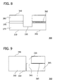
- Fig. 8 shows a partial cross-sectional view through layer 310 of device 300.
- the basic configuration is a layer 310 having two sub-layers 375, 380 as described with reference to Fig. 6 .
- Recess 330 in fluidal connection to the air above layer 310, is connected via a fluid cannel 360 to a pressure transducer (not shown).
- Channel 360 may be provided as a tube embedded in the adhesive layer 355 or in the material of (sub) layer 380 itself, e.g. by casting, etc.
- the fluid channels 360 may also be milled into the surface of the sub-layer 375 or the layer 380, whereby the adhesive layer 355 and/or the other sub-layer 380, respectively 375, provide for closing the milled channels.
- Fig. 9 shows a partial cross sectional view through a layer 310 of a device 300, in which a tube 365 is routed through a channel 385 provided in the face 350, which is in contact with the rotor blade 22 (not shown) during operation of the device 300.
- a hole 335 in layer 310 and opening 345 in an end portion of tube 365 the inner volume of tube 365 is in contact with the air above face 340.
- Tube 365 thus serves as a connection between the air or fluid above face 340 and a pressure transducer 370 (not shown, see Fig. 7 ).
- Channel 385 may be milled or cast into face 350 of layer 310.
- Tube 365 may be omitted in embodiments, which means that channel 385 then is itself the pressure conducting part between hole 335 and a sensor respectively pressure transducer (not shown in Fig. 9 ).
- Channel 385 is in this case typically closed during operation on one side by the structure itself, e.g. a surface of the wind turbine rotor blade 22, which is positioned to device 300 similarly as to device 200 in Fig. 5 .
- the pressure transducer may include means for storing measurement data and/or may include a radio transmitter for transmitting the measurement data, such as a WiFi transmitter.
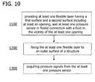
- Fig. 10 shows a schematic diagram of a method for measuring fluid pressure according to embodiments.
- the method includes providing at least one flexible layer having a first surface and a second surface including at least an opening, and at least one pressure sensor in fluidal connection with a fluid in the vicinity of the at least one opening in a block 1100. Further, fixing the at least one flexible layer to an outer surface of a structure in a block 1200; and, in a block 1300, acquiring pressure signals from the at least one pressure sensor.
- the above-described systems and methods may facilitate the measurement of fluid pressures around a structure without having to modify the structure itself. Further, the device may be quickly applied and also dismounted from a rotor blade, an airfoil or hydrofoil, a wind turbine rotor blade or other components of a wind turbine. Exemplary embodiments of systems and methods for measuring fluid pressure are described above in detail. The systems and methods are not limited to the specific embodiments described herein, but rather, components of the systems and/or steps of the methods may be utilized independently and separately from other components and/or steps described herein. For example, the device and method may be used on any airfoil for hydrofoil, and are not limited to practice with only the wind turbine systems as described herein. Rather, the exemplary embodiment can be implemented and utilized in connection with many other airfoil/hydrofoil applications.
Landscapes
- Physics & Mathematics (AREA)
- General Physics & Mathematics (AREA)
- Fluid Mechanics (AREA)
- Wind Motors (AREA)
- Measuring Fluid Pressure (AREA)
Abstract
Description
- The subject matter described herein relates generally to methods and systems for the pressure measurement on airfoils and hydrofoils, and more particularly, to methods and systems for the pressure measurement on wind turbine rotor blades.
- At least some known wind turbines include a tower and a nacelle mounted on the tower. A rotor is rotatably mounted to the nacelle and is coupled to a generator by a shaft. A plurality of blades extend from the rotor. The blades are oriented such that wind passing over the blades turns the rotor and rotates the shaft, thereby driving the generator to generate electricity.
- In order to optimize the aerodynamic properties of airfoils, hydrofoils, and particularly of wind turbine rotor blades, the pressure distribution around the profile of the same may be measured. For this purpose, a number of techniques are well known. Amongst others, it is known to drill small holes into the surface of the structure and to apply pressure tubes which are routed to a measurement system inside the structure. Further, the application of pitot tubes or pressure sensors on the surface of the profile of a foil or wing is also applied. If the pressure close to the surface of the structure shall be measured, pressure sensors are typically mounted in small holes in the surface, which allows for a measurement at face level.
- However, this involves a number of disadvantages. The surface of the rotor blade or airfoil is typically manipulated by drilling holes in which the sensors are placed. Though sensors may also be mounted to the aerodynamic face of the structure, e.g. via the use of adhesives, this can lead to an undesirable distortion of the airflow in the vicinity of the attached sensor and thus to biased or misleading measurement results. Further, for acquiring the measurement data, wires have to be installed. These are typically routed through the interior of the blade or wing, involving a significant amount of labor, which is time consuming and at least partially leads to changes in the structure of the blade or wing. Sometimes, it may also be difficult or impossible to route wires through a structure because of its structural properties or accessibility. The wires may also be installed on the surface of an airfoil or rotor blade, which requires less time and effort, but may contribute to a distortion of the airflow in the vicinity of the sensors, and thus to a degradation of the quality of the acquired data.
- In view of the above, it is desirable to have a technique which allows for the measurement of pressures and pressure gradients close to the surface of an airfoil or hydrofoil, and more particularly of a wind turbine component, and which avoids the above cited disadvantages.
- In one aspect according to the present invention, a device for measuring air pressure on a wind turbine component is provided. The device includes at least one flexible layer having a first surface adapted for fixing the layer to a structure, and having a second surface having at least one recess; at least one pressure sensor, provided in the at least one recess; and at least two wires connected to the at least one pressure sensor for connecting the at least one pressure sensor to a signal receiving unit.
- In another aspect, a device for measuring fluid pressure is provided. The device includes at least one flexible layer having a first surface adapted for fixing the layer to a structure, and having a second surface having at least one opening; at least one pressure sensor; and at least one fluid channel connecting the at least one opening and the at least one pressure sensor.
- In yet another aspect, a method of measuring fluid pressure is provided. The method includes providing at least one flexible layer having a first surface and a second surface including at least an opening, and at least one pressure sensor in fluidal connection with a fluid in the vicinity of the at least one opening; fixing the at least one flexible layer to an outer surface of a structure; and acquiring pressure signals from the at least one pressure sensor.
- Various aspects, advantages and features of the present invention are apparent from the dependent claims, the description and the accompanying drawings, in which:
-
Fig. 1 is a perspective view of an exemplary wind turbine. -
Fig. 2 is an enlarged sectional view of a portion of the wind turbine shown inFig. 1 . -
Fig. 3 is a schematic top cross sectional view on a device according to embodiments. -
Fig. 4 is a side view of a cross section of a wind turbine rotor blade with a device according to embodiments. -
Fig. 5 is a partial cross-sectional view through a device according to embodiments. -
Fig. 6 is a partial cross-sectional view through a device according to embodiments. -
Fig. 7 is a top cross-sectional view on a device according to embodiments. -
Fig. 8 is a cross-sectional view on a device according to embodiments. -
Fig. 9 is a cross-sectional view on a device according to further embodiments. -
Fig. 10 shows a schematic view of a method of measuring fluid pressure according to embodiments. - Reference will now be made in detail to the various embodiments, one or more examples of which are illustrated in each figure. Each example is provided by way of explanation and is not meant as a limitation. For example, features illustrated or described as part of one embodiment can be used on or in conjunction with other embodiments to yield yet further embodiments. It is intended that the present disclosure includes such modifications and variations.
- The embodiments described herein include a device for measuring fluid pressures around a structure without the need for making structural modifications to the structure. More specifically, the device allows for measuring an air pressure in the vicinity of wings, wind turbine rotor blades or other parts of wind turbines such as hubs or nacelle parts.
- As used herein, the term "blade" is intended to be representative of any device that provides a reactive force when in motion relative to a surrounding fluid. As used herein, the term "wind turbine" is intended to be representative of any device that generates rotational energy from wind energy, and more specifically, converts kinetic energy of wind into mechanical energy. As used herein, the term "wind generator" is intended to be representative of any wind turbine that generates electrical power from rotational energy generated from wind energy, and more specifically, converts mechanical energy converted from kinetic energy of wind to electrical power. As used herein, "wind turbine component" is intended to be representative of any part of a wind turbine, for instance, a rotor blade, a rotor hub, a nacelle, and a tower.
-
Figure 1 is a perspective view of anexemplary wind turbine 10. In the exemplary embodiment,wind turbine 10 is a horizontal-axis wind turbine. Alternatively,wind turbine 10 may be a vertical-axis wind turbine. In the exemplary embodiment,wind turbine 10 includes atower 12 that extends from asupport system 14, anacelle 16 mounted ontower 12, and arotor 18 that is coupled tonacelle 16.Rotor 18 includes arotatable hub 20 and at least onerotor blade 22 coupled to and extending outward fromhub 20. In the exemplary embodiment,rotor 18 has threerotor blades 22. In an alternative embodiment,rotor 18 includes more or less than threerotor blades 22. In the exemplary embodiment,tower 12 is fabricated from tubular steel to defme a cavity (not shown inFigure 1 ) betweensupport system 14 andnacelle 16. In an alternative embodiment,tower 12 is any suitable type of tower having any suitable height. -
Rotor blades 22 are spaced abouthub 20 to facilitate rotatingrotor 18 to enable kinetic energy to be transferred from the wind into usable mechanical energy, and subsequently, electrical energy.Rotor blades 22 are mated tohub 20 by coupling ablade root portion 24 tohub 20 at a plurality ofload transfer regions 26.Load transfer regions 26 have a hub load transfer region and a blade load transfer region (both not shown inFigure 1 ). Loads induced torotor blades 22 are transferred tohub 20 viaload transfer regions 26. - In one embodiment,
rotor blades 22 have a length ranging from about 15 meters (m) to about 91 m. Alternatively,rotor blades 22 may have any suitable length that enableswind turbine 10 to function as described herein. For example, other non-limiting examples of blade lengths include 10 m or less, 20 m, 37 m, or a length that is greater than 91 m. As wind strikesrotor blades 22 from adirection 28,rotor 18 is rotated about an axis ofrotation 30. Asrotor blades 22 are rotated and subjected to centrifugal forces,rotor blades 22 are also subjected to various forces and moments. As such,rotor blades 22 may deflect and/or rotate from a neutral, or non-deflected, position to a deflected position. - Moreover, a pitch angle or blade pitch of
rotor blades 22, i.e., an angle that determines a perspective ofrotor blades 22 with respect todirection 28 of the wind, may be changed by apitch adjustment system 32 to control the load and power generated bywind turbine 10 by adjusting an angular position of at least onerotor blade 22 relative to wind vectors. Pitch axes 34 forrotor blades 22 are shown. During operation ofwind turbine 10,pitch adjustment system 32 may change a blade pitch ofrotor blades 22 such thatrotor blades 22 are moved to a feathered position, such that the perspective of at least onerotor blade 22 relative to wind vectors provides a minimal surface area ofrotor blade 22 to be oriented towards the wind vectors, which facilitates reducing a rotational speed ofrotor 18 and/or facilitates a stall ofrotor 18. - In the exemplary embodiment, a blade pitch of each
rotor blade 22 is controlled individually by acontrol system 36. Alternatively, the blade pitch for allrotor blades 22 may be controlled simultaneously bycontrol system 36. Further, in the exemplary embodiment, asdirection 28 changes, a yaw direction ofnacelle 16 may be controlled about ayaw axis 38 to positionrotor blades 22 with respect todirection 28. - In the exemplary embodiment,
control system 36 is shown as being centralized withinnacelle 16, however,control system 36 may be a distributed system throughoutwind turbine 10, onsupport system 14, within a wind farm, and/or at a remote control center.Control system 36 includes aprocessor 40 configured to perform the methods and/or steps described herein. Further, many of the other components described herein include a processor. As used herein, the term "processor" is not limited to integrated circuits referred to in the art as a computer, but broadly refers to a controller, a microcontroller, a microcomputer, a programmable logic controller (PLC), an application specific integrated circuit, and other programmable circuits, and these terms are used interchangeably herein. It should be understood that a processor and/or a control system can also include memory, input channels, and/or output channels. - In the embodiments described herein, memory may include, without limitation, a computer-readable medium, such as a random access memory (RAM), and a computer-readable non-volatile medium, such as flash memory. Alternatively, a floppy disk, a compact disc-read only memory (CD-ROM), a magneto-optical disk (MOD), and/or a digital versatile disc (DVD) may also be used. Also, in the embodiments described herein, input channels include, without limitation, sensors and/or computer peripherals associated with an operator interface, such as a mouse and a keyboard. Further, in the exemplary embodiment, output channels may include, without limitation, a control device, an operator interface monitor and/or a display.
- Processors described herein process information transmitted from a plurality of electrical and electronic devices that may include, without limitation, sensors, actuators, compressors, control systems, and/or monitoring devices. Such processors may be physically located in, for example, a control system, a sensor, a monitoring device, a desktop computer, a laptop computer, a programmable logic controller (PLC) cabinet, and/or a distributed control system (DCS) cabinet. RAM and storage devices store and transfer information and instructions to be executed by the processor(s). RAM and storage devices can also be used to store and provide temporary variables, static (i.e., non-changing) information and instructions, or other intermediate information to the processors during execution of instructions by the processor(s). Instructions that are executed may include, without limitation, wind turbine control system control commands. The execution of sequences of instructions is not limited to any specific combination of hardware circuitry and software instructions.
-
Fig. 2 is an enlarged sectional view of a portion ofwind turbine 10. In the exemplary embodiment,wind turbine 10 includesnacelle 16 andhub 20 that is rotatably coupled tonacelle 16. More specifically,hub 20 is rotatably coupled to anelectric generator 42 positioned withinnacelle 16 by rotor shaft 44 (sometimes referred to as either a main shaft or a low speed shaft), agearbox 46, ahigh speed shaft 48, and acoupling 50. In the exemplary embodiment,rotor shaft 44 is disposed coaxial tolongitudinal axis 116. Rotation ofrotor shaft 44 rotatably drivesgearbox 46 that subsequently driveshigh speed shaft 48.High speed shaft 48 rotatably drivesgenerator 42 withcoupling 50 and rotation ofhigh speed shaft 48 facilitates production of electrical power bygenerator 42.Gearbox 46 andgenerator 42 are supported by asupport 52 and asupport 54. In the exemplary embodiment,gearbox 46 utilizes a dual path geometry to drivehigh speed shaft 48. Alternatively,rotor shaft 44 is coupled directly togenerator 42 withcoupling 50. -
Nacelle 16 also includes ayaw drive mechanism 56 that may be used to rotatenacelle 16 andhub 20 on yaw axis 38 (shown inFig. 1 ) to control the perspective ofrotor blades 22 with respect todirection 28 of the wind.Nacelle 16 also includes at least onemeteorological mast 58 that includes a wind vane and anemometer (neither shown inFig. 2 ).Mast 58 provides information to controlsystem 36 that may include wind direction and/or wind speed. In the exemplary embodiment,nacelle 16 also includes a main forward support bearing 60 and a mainaft support bearing 62. - Forward support bearing 60 and aft support bearing 62 facilitate radial support and alignment of
rotor shaft 44. Forward support bearing 60 is coupled torotor shaft 44 nearhub 20. Aft support bearing 62 is positioned onrotor shaft 44 neargearbox 46 and/orgenerator 42. Alternatively,nacelle 16 includes any number of support bearings that enablewind turbine 10 to function as disclosed herein.Rotor shaft 44,generator 42,gearbox 46,high speed shaft 48,coupling 50, and any associated fastening, support, and/or securing device including, but not limited to, support 52 and/orsupport 54, and forward support bearing 60 and aft support bearing 62, are sometimes referred to as adrive train 64. - In the exemplary embodiment,
hub 20 includes apitch assembly 66.Pitch assembly 66 includes one or morepitch drive systems 68 and at least onesensor 70. Eachpitch drive system 68 is coupled to a respective rotor blade 22 (shown inFig. 1 ) for modulating the blade pitch of associatedrotor blade 22 alongpitch axis 34. Only one of threepitch drive systems 68 is shown inFig. 2 . - In the exemplary embodiment,
pitch assembly 66 includes at least one pitch bearing 72 coupled tohub 20 and to respective rotor blade 22 (shown inFig. 1 ) for rotatingrespective rotor blade 22 aboutpitch axis 34.Pitch drive system 68 includes apitch drive motor 74,pitch drive gearbox 76, andpitch drive pinion 78.Pitch drive motor 74 is coupled to pitchdrive gearbox 76 such thatpitch drive motor 74 imparts mechanical force to pitchdrive gearbox 76.Pitch drive gearbox 76 is coupled to pitchdrive pinion 78 such thatpitch drive pinion 78 is rotated bypitch drive gearbox 76.Pitch bearing 72 is coupled to pitchdrive pinion 78 such that the rotation ofpitch drive pinion 78 causes rotation ofpitch bearing 72. More specifically, in the exemplary embodiment,pitch drive pinion 78 is coupled to pitch bearing 72 such that rotation ofpitch drive gearbox 76 rotates pitch bearing 72 androtor blade 22 aboutpitch axis 34 to change the blade pitch ofblade 22. -
Pitch drive system 68 is coupled to controlsystem 36 for adjusting the blade pitch ofrotor blade 22 upon receipt of one or more signals fromcontrol system 36. In the exemplary embodiment,pitch drive motor 74 is any suitable motor driven by electrical power and/or a hydraulic system that enablespitch assembly 66 to function as described herein. Alternatively,pitch assembly 66 may include any suitable structure, configuration, arrangement, and/or components such as, but not limited to, hydraulic cylinders, springs, and/or servo-mechanisms. Moreover,pitch assembly 66 may be driven by any suitable means such as, but not limited to, hydraulic fluid, and/or mechanical power, such as, but not limited to, induced spring forces and/or electromagnetic forces. In certain embodiments,pitch drive motor 74 is driven by energy extracted from a rotational inertia ofhub 20 and/or a stored energy source (not shown) that supplies energy to components ofwind turbine 10. -
Fig. 3 shows adevice 200 for measuring air pressure, respectively a pressure distribution around a wing orrotor blade 22 according to embodiments. The device includes alayer 210 made from or including a flexible material. Thelayer 210 has typically a rectangular or trapezoidal shape and a thickness significantly smaller than its width and length. The layer is provided withpressure sensors 220, which are typically placed inrecesses 230 or openings in one of its surfaces, typically the outward facingsurface 240. Theopposite surface 250 may also have openings, which are typically covered by the structure after the application of the film. - Typically, each sensor is connected to at least two
wires 260 for connecting it to asignal receiving unit 270. For illustrational purposes, the at least twowires 260 are shown as one line inFig. 3 . This unit may be mounted to thelayer 210 or may be provided separately from thedevice 200. There are several options how thewires 270 are guided from thesensors 220 to the signal receiving unit, which are described further below. - The
layer 210 includes a flexible material, such that the layer may be adapted to the outline of a wind turbine rotor blade or an airfoil etc. The layer may include polymers, such as (non-limiting) rubber, silicone, polyethylene, polyurethane, polypropylene, polyvinylchloride, epoxy or polyester resin, PEEK, polyolefin, and may also include additional or alternative materials such as fibers or metal. The material of thelayer 210 is not particulary limited. The main requirements are flexibility, such that the layer may be adapted to the outline of the rotor blade, and that the material may be formed respectively modified in order to placesensors 220 in the holes/recesses 230. - The length of the layer may vary from 5 % to 150 %, more typically from 10 % to 120 % of the blade airfoil arc length, even more typically the length covers the arc length plus a few percent (from 100 % to 110 %). The width of the layer depends on the number of sensors in the layer. A typical number of sensors per device is 3 to 60, more typically 5 to 50. As shown in
Fig. 3 , the sensors are offset to each other, for instance they may be placed on a diagonal line across the layer 210 (dashed line). This offset provides that when the layer is fixed to a rotor blade or other structure, the air flow behind onesensor 220 is not influencing or disturbing the air flow (which is basically in a direction of the longitudinal axis of the layer, indicated by the arrow) of another sensor. Accordingly, the nine sensors shown inFig. 3 may require, in a non-limiting example, a width of the layer of about half a chord length plus the distance from theoutermost sensors 220 to the edge of the layer, hence for a typical chord of 1 m roughly about 50 cm. Other sensor numbers, dimensions oflayer 210 or configurations may result in other outer dimensions. Expressed differently, an angle between the staggering direction (dashed line) and the air flow (arrow) typically is in the order of 3 to 30 degrees, more typically 7 to 15 degrees. The layer has a typical thickness of from 0.5 mm to 6 mm, more typically from 1 mm to 3 mm, for the application of current state of the art pressure sensors, such as piezo sensors. Depending on the type of application and pressure sensors, other thickness values may be suitable. - The
signal receiving unit 270 as shown inFig. 3 typically includes a microcontroller and/or a microprocessor and random access memory. Different from the shown embodiment, theunit 270 may also be provided outsidelayer 210 in other embodiments. Theunit 270 includes a plurality of electrical ports for the connection of the signals fromsensors 220 viawires 260. Typically, theunit 270 samples the sensor signals at the different inputs at a certain time rate. If the pressure sensors are piezo sensors, a high timely resolution of the pressure signal coming from the piezo sensor is achieved. With piezo sensors, the sample rate may typically be up to 400 kHz, more typically up to 200 kHz. In turbulent flows, such high sampling frequencies may be necessary in order to resolve the occurring pressure fluctuations. In order to achieve a suitable timely resolution with a lower sampling rate, e.g. 20 kHz, one may accept a certain loss of information and aim to recover it by computational turbulence and sensor response modeling, if required. - The
unit 270 may further be provided to store the collected data over a longer period of time. Preferably, theunit 270 is equipped with a radio transmitter for transmitting the collected data to another instance, e.g., a personal computer provided in a distance from the rotor blade to which thedevice 200 is applied. Due to widespread use and availabilty, solutions based on computer WiFi networks, e.g. in the 2.4 GHz band, respectively according to the various IEEE 802.11 standards, may be used for data transmission as well. - For measuring air pressure around a
rotor blade 22, particularly in a boundary layer, thelayer 210 is placed on the outer surface ofrotor blade 22, such that it is wrapped around the leading edge and protrudes on both faces of the blade towards the trailing edge, such as is schematically shown inFig. 4 . The exact length of thelayer 210, such as its exact placement on therotor blade 22 depends strongly on the purpose of the measurement process, for instance which area of the blade profile shall be examined in terms of air pressure distribution. For instance, the length of the layer may be adapted such that only one side of therotor blade 22 is covered from the leading edge to the trailing edge. In other embodiments, the layer may be adapted such that it starts at the trailing edge on one side, protrudes up to the leading edge and continues on the other side of the rotor blade to the trailing edge, such that it is possible to provide sensors substantially all around the blade profile. Thelayer 210 is typically fixed to a surface of the rotor blade with adhesive or sticky elements, such as an adhesive tape, a glue, or magnets. - The
pressure sensor 220 is typically a piezo sensor. Piezo sensors provide a good time resolution and are thus suitable to monitor fast pressure changes in the boundary layer aroundrotor blade 22, which allows for the monitoring of dynamic turbulent pressure changes in the boundary layer around the profile of arotor blade 22. As can be seen inFig. 3 , eachsensor 220 is typically placed in thelayer 210 such that the sensors have different distances from oneend 205 of thelayer 210, which allows for a monitoring of the air pressure up to the entire depth of the rotor blade profile on both sides. A typical cylindrical miniature piezo sensor has (in a non-limiting example) the following dimensions: a diameter of about 1.5 mm and a thickness of about 0.5 mm. Thus, recesses 220 inlayer 210 have to be provided accordingly. They may be provided slightly smaller, e.g. from 1.2 mm to 1.4 mm diameter, such that the sensor is stably held in the flexible material oflayer 210. The piezo sensors can typically also capture the average static surface pressures in order to obtain the pressure distribution around the blade. -
Fig. 5 shows how apressure sensor 220 is integrated in theflexible layer 210. The layer is typically fixed to the rotor blade 22 (only schematically shown) with itssecond surface 250. Thesurface 225 of the sensor is typically the pressure sensitive face of the sensor, such that it is in direct contact with the air or fluid around thelayer 210. The twowires 260 are connected tosensor 220, they transmit the sensor signal to the signal receiving unit 270 (not shown).Channels 285 for thewires 260 may be milled in thesecond surface 250 of thelayer 210, such that the wires are provided in these channels. Hence, the channels are on the side oflayer 210 covered by the structure, e.g. therotor blade 22, whendevice 200 is mounted torotor blade 22. Anadhesive tape 265 or other sticky material providing stable contact between therotor blade 22 anddevice 200 is provided therebetween. - In other embodiments, other types of sensors, such as magnetodynamic sensors or condensor/electret microphones may be used, which may require a higher number of wires for operation, for instance a third and fourth wire for feeding a voltage to the sensor. The
pressure sensor 220 is provided such that asurface 225 of the pressure sensor is substantially flush with thesecond face 240 of thelayer 210. "Substantially flush" is defined herein in that the greatest distance (in a direction perpendicular to the layer) between a geometrical spot on thesurface 225 of the sensor and the surface plane of thelayer 210 is smaller than 0.3 mm, more typically smaller than 0.2 mm, even more typically smaller than 0.01 mm. - In
Fig. 6 , a cross-sectional view of afurther device 200 according to embodiments is shown. Therein, thelayer 210 includes twosub-layers sticky material 255. Thewires 260 are typically provided in theadhesive layer 255. During manufacturing of thelayer 210, atfirst sub-layer 270 is provided. Subsequently,sensors 220 are placed intorecesses 230, and thewires 260 are positioned on the sub-layer 270, for instance in an arrangement as shown inFig. 3 . Then, the layer ofadhesive material 255 is provided.Wires 260 may also be placed onto thelayer 255 of adhesive material after its application. The wires are manually pressed on or into thelayer 255, such that they are typically at least partly surrounded by the adhesive. Thelayer 255 may also include materials like silicone or another polymer, which preferably provides flexibility and adhesiveness. In other embodiments, thelayer 210 may include twosublayers wires 260 are routed, and the other sublayer is provided as a polymeric material. Suitable materials include (non-limiting) rubber, silicone, polyethylene, polyurethane, polypropylene, polyvinylchloride, epoxy or polyester resin, PEEK, and polyolefin. -
Fig. 7 shows a partial cross-sectional view of adevice 300 for measuring fluid pressure according to further embodiments. This device has alayer 310 including a flexible material similar to the device ofFig. 3 . In the layer, openings respectively recesses 330 are formed. These openings are typically each connected by afluid channel 360 to a common pressure scanner respectivelytransducer 370, wherein a plurality of pressure sensors are typically integrated. - The fluid channel typically has a cross sectional area from 0.3 mm2 to 25 mm2, more typically from 0.7 mm2 to 10 mm2 , and typically a rectangular, elliptical or round cross section.
- The
device 300 is used to measure static or quasi-static pressures in the vicinity of a rotor blade to which it is attached or fixed. As theopenings 330 are connected via thefluid channels 360 to thepressure transducer 370, different sensors in the transducer are in fluidal connection to the air surrounding thelayer 310 atopening 330. Hence, the transducer measures the static air pressure at theopenings 330.Layer 310 ofdevice 300 has basically the same dimensions aslayer 210 described with respect toFig. 3 . A pitot-type orPrandtl tube 390 may be used to measure a reference pressure for comparison with the pressure data measured by the pressure sensors in thetransducer 370. Via the sensors integrated in thetransducer 370, the pressures are measured at a certain rate. Depending on the application, the interval between measurements may be up to several seconds, relating to a scan rate well below 1 Hz, e.g. 0.05 Hz; the scan rate may also be up to 500 Hz. Hence, the scan rate may be from 0.05 Hz to 500 Hz, more typically from 1 Hz to 40 Hz. -
Fig. 8 shows a partial cross-sectional view throughlayer 310 ofdevice 300. The basic configuration is alayer 310 having twosub-layers Fig. 6 .Recess 330, in fluidal connection to the air abovelayer 310, is connected via afluid cannel 360 to a pressure transducer (not shown).Channel 360 may be provided as a tube embedded in theadhesive layer 355 or in the material of (sub)layer 380 itself, e.g. by casting, etc. - The
fluid channels 360 may also be milled into the surface of the sub-layer 375 or thelayer 380, whereby theadhesive layer 355 and/or theother sub-layer 380, respectively 375, provide for closing the milled channels. -
Fig. 9 shows a partial cross sectional view through alayer 310 of adevice 300, in which atube 365 is routed through achannel 385 provided in theface 350, which is in contact with the rotor blade 22 (not shown) during operation of thedevice 300. Viahole 335 inlayer 310 andopening 345 in an end portion oftube 365, the inner volume oftube 365 is in contact with the air aboveface 340.Tube 365 thus serves as a connection between the air or fluid aboveface 340 and a pressure transducer 370 (not shown, seeFig. 7 ).Channel 385 may be milled or cast intoface 350 oflayer 310. -
Tube 365 may be omitted in embodiments, which means thatchannel 385 then is itself the pressure conducting part betweenhole 335 and a sensor respectively pressure transducer (not shown inFig. 9 ).Channel 385 is in this case typically closed during operation on one side by the structure itself, e.g. a surface of the windturbine rotor blade 22, which is positioned todevice 300 similarly as todevice 200 inFig. 5 . - The pressure transducer may include means for storing measurement data and/or may include a radio transmitter for transmitting the measurement data, such as a WiFi transmitter.
-
Fig. 10 shows a schematic diagram of a method for measuring fluid pressure according to embodiments. The method includes providing at least one flexible layer having a first surface and a second surface including at least an opening, and at least one pressure sensor in fluidal connection with a fluid in the vicinity of the at least one opening in ablock 1100. Further, fixing the at least one flexible layer to an outer surface of a structure in ablock 1200; and, in ablock 1300, acquiring pressure signals from the at least one pressure sensor. - The above-described systems and methods may facilitate the measurement of fluid pressures around a structure without having to modify the structure itself. Further, the device may be quickly applied and also dismounted from a rotor blade, an airfoil or hydrofoil, a wind turbine rotor blade or other components of a wind turbine. Exemplary embodiments of systems and methods for measuring fluid pressure are described above in detail. The systems and methods are not limited to the specific embodiments described herein, but rather, components of the systems and/or steps of the methods may be utilized independently and separately from other components and/or steps described herein. For example, the device and method may be used on any airfoil for hydrofoil, and are not limited to practice with only the wind turbine systems as described herein. Rather, the exemplary embodiment can be implemented and utilized in connection with many other airfoil/hydrofoil applications.
- Although specific features of various embodiments of the invention may be shown in some drawings and not in others, this is for convenience only. In accordance with the principles of the invention, any feature of a drawing may be referenced and/or claimed in combination with any feature of any other drawing.
- This written description uses examples to disclose the invention, including the preferred mode, and also to enable any person skilled in the art to practice the invention, including making and using any devices or systems and performing any incorporated methods. While various specific embodiments have been disclosed in the foregoing, those skilled in the art will recognize that the spirit and scope of the claims allows for equally effective modifications. Especially, mutually non-exclusive features of the embodiments described above may be combined with each other. The patentable scope of the invention is defined by the claims, and may include other examples that occur to those skilled in the art. Such other examples are intended to be within the scope of the claims if they have structural elements that do not differ from the literal language of the claims, or if they include equivalent structural elements with insubstantial differences from the literal language of the claims.
- Various aspects and embodimens of the present invention are defined by the following numbered clauses:
- 1. A device for measuring air pressure on a wind turbine component, comprising:
- a) at least one flexible layer having a first surface adapted for fixing the layer to a structure, and having a second surface having at least one recess;
- b) at least one pressure sensor, provided in the at least one recess;
- c) at least two wires connected to the at least one pressure sensor for connecting the at least one pressure sensor to a signal receiving unit.
- 2. The device of
clause 1, wherein the at least one pressure sensor is provided such that at least one surface of the at least one pressure sensor is substantially flush with the second face of the at least one layer. - 3. The device of any preceding clause, wherein the at least one pressure sensor is a piezoelectric pressure sensor.
- 4. The device of any preceding clause, further comprising a signal receiving unit connected to the at least one pressure sensor via the at least two wires.
- 5. The device of any preceding clause, wherein the signal receiving unit comprises a radio transmitter.
- 6. The device of any preceding clause, wherein the at least two wires protrude parallel to the at least one layer.
- 7. The device of any preceding clause, wherein the at least one layer comprises an element selected from the list consisting of: a polymer, and a metal.
- 8. The device of any preceding clause, wherein the at least one layer comprises at least two sub-layers, and wherein the at least two wires protrude between the at least two sub-layers.
- 9. The device of any preceding clause, wherein a plurality of sensors are provided in the at least one layer, and wherein each sensor is connected to the signal receiving unit by at least two wires.
- 10. A device for measuring fluid pressure, comprising:
- a) at least one flexible layer having a first surface adapted for fixing the layer to a structure, and having a second surface having at least one opening;
- b) at least one pressure sensor;
- c) at least one fluid channel connecting the at least one opening and the at least one pressure sensor.
- 11. The device of any preceding clause, wherein the at least one layer comprises at least one element selected from the list consisting of: a polymer, and a metal.
- 12. The device of any preceding clause, further comprising a plurality of fluid channels connecting a plurality of pressure sensors and a plurality of openings in the second face of the at least one layer.
- 13. The device of any preceding clause, further comprising at least one pressure transducer including the plurality of pressure sensors.
- 14. The device of any preceding clause, wherein the at least one fluid channel has a cross sectional area from 0.3 mm2 to 25 mm2.
- 15. A method of measuring fluid pressure, comprising:
- a) providing at least one flexible layer having a first surface and a second surface including at least an opening, and at least one pressure sensor in fluidal connection with a fluid in the vicinity of the at least one opening;
- b) fixing the at least one flexible layer to an outer surface of a structure; and,
- c) acquiring pressure signals from the at least one pressure sensor.
- 16. The method of any preceding clause, wherein fixing comprises the use of an adhesive element, and wherein the structure is an airfoil.
- 17. The method of any preceding clause, wherein fixing comprises the use of adhesive tape, a glue, or a magnet.
- 18. The method of any preceding clause, wherein signals are acquired from a plurality of pressure sensors integrated in a pressure transducer, and wherein a plurality of fluid channels connect the pressure sensors with a plurality of openings in the second face of the at least one flexible layer.
- 19. The method of any preceding clause, wherein a Pitot-static tube is used to measure a reference pressure.
- 20. The method of any preceding clause, wherein signals are acquired from a plurality of piezoelectric pressure sensors located at different positions in the at least one layer, and wherein the sensors provide signals related to the fluid pressure at their respective position, and wherein the sensor signals are acquired with a frequency between the rotor rotational frequency and 400 kHz.
Claims (15)
- A device (200) for measuring fluid pressure, comprising:at least one flexible layer (210) having a first surface adapted for fixing the layer to a structure, and having a second surface having at least one recess;at least one pressure sensor (370), provided in the at least one recess;at least two wires (260) connected to the at least one pressure sensor (370) for connecting the at least one pressure sensor to a signal receiving unit (270).
- The device (200) of claim 1, wherein the at least one pressure sensor (370) is provided such that at least one surface (250) of the at least one pressure sensor is substantially flush with the second face of the at least one layer.
- The device (200) of any preceding claim, wherein the at least one pressure sensor (370) is a piezoelectric pressure sensor, and wherein a signal receiving unit (270) is connected to the at least one pressure sensor via the at least two wires.
- The device (200) of any preceding claim, wherein the at least one layer (250) comprises an element selected from the list consisting of: a polymer, and a metal.
- The device (200) of any preceding claim, wherein the at least one layer (250) comprises at least two sub-layers, and wherein the at least two wires protrude between the at least two sub-layers.
- The device (200) of any preceding claim, wherein a plurality of sensors (370) are provided in the at least one layer (250), and wherein each sensor is connected to the signal receiving unit by at least two wires.
- A device (200) for measuring fluid pressure, comprising:at least one flexible layer (250) having a first surface adapted for fixing the layer to a structure, and having a second surface having at least one opening;at least one pressure sensor;at least one fluid channel connecting the at least one opening and the at least one pressure sensor.
- The device (200) of claim 7, wherein the at least one layer (250) comprises an element selected from the list consisting of: a polymer, and a metal.
- The device (200) of claim 7 or claim 8, further comprising a plurality of fluid channels connecting a plurality of pressure sensors and a plurality of openings in the second face of the at least one layer, and wherein the plurality of pressure sensors is included in a pressure transducer.
- The device (200) of any one of claims 7 to 9, wherein the at least one fluid channel has a cross sectional area from 0.3 mm2 to 25 mm2.
- A method of measuring fluid pressure, comprising:a) providing (1100) at least one flexible layer (250) having a first surface and a second surface including at least an opening, and at least one pressure sensor in fluidal connection with a fluid in the vicinity of the at least one opening;b) fixing (1200) the at least one flexible layer to an outer surface of a structure; andc) acquiring (1300) pressure signals from the at least one pressure sensor (370).
- The method of claim 11, wherein fixing (1200) comprises the use of an adhesive element, and wherein the structure is an airfoil.
- The method of claim 11 or claim 12, wherein fixing (1200) comprises the use of adhesive tape, a glue, or a magnet.
- The method of any of claims 11 to 13, wherein signals are acquired from a plurality of pressure sensors (370) integrated in a pressure transducer, and wherein a plurality of fluid channels connect the pressure sensors with a plurality of openings in the second face of the at least one flexible layer.
- The method of any of claims 11 to 14, wherein signals are acquired from a plurality of piezoelectric pressure sensors located at different positions in the at least one layer (250), and wherein the sensors provide signals related to the fluid pressure at their respective position, and wherein the sensor signals are acquired with a frequency between the rotor rotational frequency and 400 kHz.
Applications Claiming Priority (1)
| Application Number | Priority Date | Filing Date | Title |
|---|---|---|---|
| US13/099,644 US8479581B2 (en) | 2011-05-03 | 2011-05-03 | Device and method for measuring pressure on wind turbine components |
Publications (3)
| Publication Number | Publication Date |
|---|---|
| EP2520919A2 true EP2520919A2 (en) | 2012-11-07 |
| EP2520919A3 EP2520919A3 (en) | 2017-08-02 |
| EP2520919B1 EP2520919B1 (en) | 2022-06-29 |
Family
ID=45525365
Family Applications (1)
| Application Number | Title | Priority Date | Filing Date |
|---|---|---|---|
| EP12166369.4A Active EP2520919B1 (en) | 2011-05-03 | 2012-05-02 | Device and method for measuring pressure on wind turbine components |
Country Status (5)
| Country | Link |
|---|---|
| US (1) | US8479581B2 (en) |
| EP (1) | EP2520919B1 (en) |
| CN (1) | CN102778330B (en) |
| DK (1) | DK2520919T3 (en) |
| ES (1) | ES2927621T3 (en) |
Cited By (1)
| Publication number | Priority date | Publication date | Assignee | Title |
|---|---|---|---|---|
| EP4194683A1 (en) * | 2021-12-09 | 2023-06-14 | General Electric Renovables España S.L. | Wind turbine blades, wind turbine blade assemblies and related methods |
Families Citing this family (12)
| Publication number | Priority date | Publication date | Assignee | Title |
|---|---|---|---|---|
| US8327710B2 (en) * | 2010-07-29 | 2012-12-11 | General Electric Company | System for estimating a condition of non-conductive hollow structure exposed to a lightning strike |
| US8733156B2 (en) * | 2012-07-16 | 2014-05-27 | United Technologies Corporation | PMC laminate embedded hypotube lattice |
| US20170167465A1 (en) * | 2014-07-15 | 2017-06-15 | Okinawa Institute Of Science And Technology School Corporation | Wave energy converter |
| EP3073241A1 (en) * | 2014-11-28 | 2016-09-28 | Siemens Aktiengesellschaft | Analyzing the boundary layer of a rotor blade |
| CN104807609B (en) * | 2015-05-04 | 2017-04-19 | 中国科学院工程热物理研究所 | Pneumatic wind blade pressure testing structure |
| CN105092139B (en) * | 2015-08-31 | 2018-07-06 | 中国空气动力研究与发展中心计算空气动力研究所 | Pneumatic equipment bladess surface pressure measurement cover and its measuring system |
| CN105823581B (en) * | 2016-05-12 | 2018-12-14 | 江苏大学 | A system and method for wirelessly measuring the surface pressure of pump impeller blades |
| CN107850496B (en) * | 2016-06-13 | 2021-03-19 | 深圳市汇顶科技股份有限公司 | A pressure detection system, module and method |
| CN107345846B (en) * | 2017-07-28 | 2019-04-16 | 大连理工大学 | A kind of free vertical and twisted coupling vibration flow tunnel testing device of large amplitude |
| US11155347B2 (en) | 2019-04-02 | 2021-10-26 | Textron Innovations Inc. | Rotorcraft blade grip |
| CN112556918B (en) * | 2021-02-22 | 2021-04-30 | 中国空气动力研究与发展中心低速空气动力研究所 | Differential pressure sensor and pressure measuring device |
| CN113252280B (en) * | 2021-04-20 | 2021-09-21 | 中国空气动力研究与发展中心高速空气动力研究所 | Nacelle test device capable of simulating air intake and exhaust simultaneously |
Family Cites Families (77)
| Publication number | Priority date | Publication date | Assignee | Title |
|---|---|---|---|---|
| JPS55107953A (en) | 1979-02-10 | 1980-08-19 | Horiba Ltd | Magnetic oxygen analyzer |
| BE898079A (en) | 1983-10-25 | 1984-02-15 | Centre Rech Metallurgique | Hot metal ingot surface cleaning tool - includes rotating scrapers on shaft with adjustable pressure rod for cleaning prior to temp. measurement |
| DE3942020C2 (en) | 1989-12-20 | 1993-11-04 | Vega Grieshaber Gmbh & Co | PRESSURE GAUGE FOR HYDROSTATIC LEVEL MEASUREMENT WITH A CAPACITIVE PRESSURE CONVERTER |
| US5186046A (en) | 1990-08-20 | 1993-02-16 | Board Of Regents Of The University Of Washington | Surface pressure measurement by oxygen quenching of luminescence |
| DE4105211C2 (en) | 1991-02-20 | 1996-01-18 | Me Meerestechnik Elektronik Gm | Partial gas pressure sensor with membrane |
| JPH04309828A (en) | 1991-04-09 | 1992-11-02 | Kubota Corp | How to measure the surface pressure of a rubber ring |
| DE4139025C1 (en) | 1991-11-27 | 1992-10-22 | Siemens Ag, 8000 Muenchen, De | Fibre=optic pressure sensor for lithotripsy - has bend in fibre=optic waveguide with material removed to form surface exposed to fluid for measurement of refractive index |
| DE4240782A1 (en) | 1992-12-04 | 1994-06-09 | Hildegard Roethel | Pressure measurement on surface area of resting human body and measuring equipment - uses plastic mat with active area of sensors connected to recorder to prevent blood flow deficiency in area of wound |
| US5409739A (en) | 1993-09-17 | 1995-04-25 | University Technologies International Inc. | Monolayer coating |
| DE4441081A1 (en) | 1994-11-18 | 1996-05-30 | Jenoptik Technologie Gmbh | Arrangement for the exact determination of an applanation area for eye pressure measurement |
| DE19603386A1 (en) | 1996-01-31 | 1997-08-07 | Lauda Dr R Wobser Gmbh & Co Kg | Measurement and control of surfactant solution surface tension using bubble excess pressure tensiometer |
| US5961080A (en) * | 1996-11-15 | 1999-10-05 | The University Of Mississippi | System for efficient control of flow separation using a driven flexible wall |
| US6253166B1 (en) | 1998-10-05 | 2001-06-26 | The United States Of America As Represented By The Administrator Of The National Aeronautics And Space Administration | Stable algorithm for estimating airdata from flush surface pressure measurements |
| DE19910222C2 (en) | 1999-03-09 | 2002-02-28 | Abb Patent Gmbh | Method and device for determining a steam temperature |
| DE19910301A1 (en) | 1999-03-09 | 2000-09-14 | Zeliha Demirplak | Device for optical measurement and representation of pressures and pressure waves in liquid and gaseous media uses light of planer light source reflected from surface of prism to be recorded by camera |
| DE19933631C2 (en) | 1999-07-17 | 2003-03-13 | Sita Messtechnik Gmbh | Method for the static measurement of the surface tension of liquids |
| TW522500B (en) | 1999-07-28 | 2003-03-01 | Winbond Electronics Corp | Measurement of surface pressure distribution of whole wafer surface and feedback method |
| DE19939547A1 (en) | 1999-08-20 | 2001-02-22 | Volkswagen Ag | Device for determining position-resolved sound power at surface of stimulable object suitable for generating acoustic oscillations has sound pressure signal measurement probe |
| GB2355801B (en) | 1999-10-29 | 2003-07-30 | Transense Technologies Plc | Interrogation of surface acoustical wave devices |
| DE19963786A1 (en) | 1999-12-30 | 2001-07-05 | Aktiv Sensor Gmbh | Pressure measurement element is component of semiconductor wafer whose base surface is fully joined to body of same or approximately same dimensions, different coefficient of elasticity |
| DE10040180B4 (en) | 2000-08-17 | 2007-07-26 | Vega Grieshaber Kg | Level or pressure measuring sensors with dirt-repellent and / or self-cleaning properties |
| DE20023063U1 (en) | 2000-08-17 | 2003-07-03 | Vega Grieshaber Kg, 77709 Wolfach | Fill level and pressure measurement sensor has surface protrusions of liquid-repellent material at suitable distances so that liquid can run off surface without leaving residues |
| DE10052053A1 (en) | 2000-10-19 | 2002-04-25 | Endress Hauser Gmbh Co | Pressure measurement cell has contact pin fed through base body to electrode for capacitance measurement; contact pin, jointing solder and membrane bed form smooth surface |
| DE10056993A1 (en) | 2000-11-17 | 2002-05-29 | Peter Jaenker | Piezo-ceramic force sensor for motor vehicle, machine or engine use for measurement of forces applied to a pressure sensitive surface has a very small size allowing its use in small channels, etc. |
| FR2818370B1 (en) | 2000-12-20 | 2003-03-28 | France Etat Ponts Chaussees | METHOD AND DEVICE FOR MEASURING THE PLANEITY OF A SURFACE |
| US6662647B2 (en) * | 2001-01-09 | 2003-12-16 | Honeywell International Inc. | Conformal fluid data sensor |
| US6561020B2 (en) | 2001-05-08 | 2003-05-13 | Rosemount Aerospace Inc. | Method to calculate sideslip angle and correct static pressure for sideslip effects using inertial information |
| US6604029B2 (en) | 2001-05-08 | 2003-08-05 | Rosemount Aerospace Inc. | Multi-function air data probes using neural network for sideslip compensation |
| US6594559B2 (en) | 2001-05-08 | 2003-07-15 | Rosemount Aerospace Inc. | Iterative method of aircraft sideslip compensation for multi-function probe air data systems |
| TW493744U (en) | 2001-06-01 | 2002-07-01 | Aidc Aerospace Ind Dev Corp | Three-dimension pressure-bearing surface measurement apparatus structure |
| US6543298B2 (en) | 2001-07-13 | 2003-04-08 | Rosemount Aerospace Inc. | Method of reducing total temperature errors and multi-function probe implementing same |
| US6761057B2 (en) | 2001-09-13 | 2004-07-13 | Rosemount Aerospace Inc. | Error detection and fault isolation for multi-function air data probes and systems |
| DE10155135B4 (en) | 2001-10-12 | 2006-04-27 | Ifm Electronic Gmbh | Measuring device for determining the position of an object relative to a reference surface |
| DE10159943A1 (en) | 2001-12-06 | 2003-06-18 | Hans Thoma | Arrangement for measuring compressive, tensile and surface forces applied to a rider's saddle or horse's equipment using a pressure measurement insert placed between layers of interest |
| DE10203794A1 (en) | 2002-01-31 | 2003-08-21 | Rexroth Mecman Gmbh | Measurement arrangement for optical position detection of piston rod for pressure agent cylinder scans surface of piston rod, which moves axially in cylinder and calculates moved distance using pixel displacement |
| DE20220387U1 (en) | 2002-01-31 | 2003-07-03 | Rexroth Mecman GmbH, 30453 Hannover | Measurement arrangement for optical position detection of piston rod for pressure agent cylinder scans surface of piston rod, which moves axially in cylinder and calculates moved distance using pixel displacement |
| CH695709A5 (en) | 2002-02-20 | 2006-07-31 | Schweizerisches Inst Zur Foerd | High pressure cap for calorimetric measurement, has sealing washer resting on circumferential bearing surface of crucible, where crucible or washer exhibits lapped surface that supports cold welding |
| DE10211198A1 (en) | 2002-03-14 | 2003-09-25 | Fag Kugelfischer Ag & Co Kg | Surface wave sensor for pressure, acceleration and surface strain measurement has additional reflectors for temperature measurement with said measurements used for temperature compensation of the other measurements |
| DE20205851U1 (en) | 2002-04-15 | 2002-07-11 | Goldberg, Zinovi, Dipl.-Ing., 51149 Köln | pressure sensor |
| US6668640B1 (en) | 2002-08-12 | 2003-12-30 | Rosemount Aerospace Inc. | Dual-channel electronic multi-function probes and methods for realizing dissimilar and independent air data outputs |
| DE10241442B4 (en) | 2002-09-06 | 2005-08-11 | Maha Maschinenbau Haldenwang Gmbh & Co. Kg | Device for detecting parasitic losses |
| DE10243897A1 (en) | 2002-09-21 | 2004-04-01 | Daimlerchrysler Ag | Piezoelectric pressure measurement device or actuator has a pressure measurement element in the form of a piezoelectric layer deposited on the surface of a first pressure transmitting body with a covering metallic electrode layer |
| CN1203809C (en) | 2002-11-22 | 2005-06-01 | 天津市先石光学技术有限公司 | Measurement condition reproducing device and method based on body's surface texture characteristic and contact pressure |
| US7379839B2 (en) | 2002-12-23 | 2008-05-27 | Rosemount Aerospace, Inc. | Multi-function air data probes employing neural networks for determining local air data parameters |
| DE10301948A1 (en) | 2003-01-20 | 2004-06-09 | Siemens Ag | Device for measuring pressure exerted by patient on contact surface of large image-generating medical device has pressure measurement arrangement and device for indicating pressure to patient |
| NO318964B1 (en) | 2003-02-11 | 2005-05-30 | Klaveness Skofabrikk As | Painting of three-dimensional surfaces under hydrostatic or gas pressure |
| KR100535555B1 (en) | 2003-07-10 | 2005-12-08 | 현대자동차주식회사 | Pressure measuring device of duct |
| US20050061672A1 (en) | 2003-09-24 | 2005-03-24 | Burns Norman Lee | Surface characterization through pressure-based electroosmosis measurement |
| ATE506607T1 (en) | 2003-11-05 | 2011-05-15 | Innovative Scient Solutions Inc | METHOD FOR DETERMINING SURFACE CONTACT FORCE |
| KR100557144B1 (en) | 2004-01-12 | 2006-03-03 | 삼성전자주식회사 | Ethernet Passive Optical Subscriber Network for Broadcast Communication Convergence using Time Division Multiplexing |
| DE202004004267U1 (en) | 2004-03-18 | 2004-07-01 | Stock Beregnungstechnik Gmbh & Co. Kg | Combined flow rate and pressure measurement assembly for a surface irrigation installation comprises a pressure measurement unit, flow restrictor, valve and flow meter connected in series for insertion between an inlet and outlet |
| DE102004013819A1 (en) | 2004-03-20 | 2005-10-06 | Volkswagen Ag | A switch including a pressure measurement layer with an operating surface, a pressure dependent resistor and an intermediate layer useful for automobile interiors |
| DE202004012573U1 (en) | 2004-08-10 | 2004-12-09 | Krüss GmbH, Wissenschaftliche Laborgeräte | Single-hand operated bubble-pressure tensometer for measuring dynamic surface tension of liquid, controls measurement at apparatus, or via personal computer |
| US7307702B1 (en) | 2004-08-13 | 2007-12-11 | The United States Of America As Represented By The Secretary Of The Navy | Color switchable stress-fracture sensor for damage control |
| US7257470B2 (en) | 2004-10-29 | 2007-08-14 | Rosemount Aerospace Inc. | Fault isolation method and apparatus in artificial intelligence based air data systems |
| DE102004055220B4 (en) | 2004-11-16 | 2018-03-29 | Implandata Ophthalmic Products Gmbh | Device for intraocular pressure measurement |
| DE102005017408A1 (en) | 2004-12-21 | 2006-06-29 | Cross Hüller GmbH | Control method for checking the setting down of a workpiece, by measurement of the pressure of compressed air fed into a gap between the workpiece and its support surface to ensure it does not exceed a reference value |
| US7213454B2 (en) | 2005-04-06 | 2007-05-08 | Rosemount Aerospace Inc. | Method and apparatus for obtaining improved accuracy and range for air data parameters inferred from independent measurements of interdependent pressures |
| JP4852264B2 (en) | 2005-06-23 | 2012-01-11 | 株式会社アルバック | Stylus type step gauge for surface shape measurement and its needle pressure correction method |
| DE102005036410A1 (en) | 2005-07-29 | 2007-02-01 | Biocam Gmbh | Method for determining the oxygen partial pressure distribution in at least one tissue surface section, in particular skin tissue surface section |
| DE102006012998A1 (en) | 2005-10-05 | 2007-09-27 | Hidde, Axel R., Dr. Ing. | Pressure balance screw with pipe membrane e.g. switchgear cubicle, has pressure balance measurement of small construction and having large diaphragm surface for cabled and or electrical connection to housing |
| DE202006004829U1 (en) | 2006-03-22 | 2006-11-16 | Hidde, Axel R., Dr. Ing. | Pressure balance screw with pipe membrane e.g. switchgear cubicle, has pressure balance measurement of small construction and having large diaphragm surface for cabled and or electrical connection to housing |
| DE102006014106B3 (en) | 2006-03-24 | 2007-08-30 | RUHR-UNIVERSITäT BOCHUM | Apparatus and method for measuring the density of a plasma |
| DE202006017215U1 (en) | 2006-05-15 | 2007-02-01 | Knick Elektronische Messgeräte GmbH & Co. KG | Sensor holder part for change fittings for glass electrodes for pH value or redox measurement has pressure medium connection sleeve for pushing into casing with inner supporting surface for variable fixing of reservoir according to length |
| KR100798481B1 (en) | 2006-11-15 | 2008-01-28 | 한국표준과학연구원 | Fingerprint reader with surface pressure sensing |
| PL210958B1 (en) | 2007-04-02 | 2012-03-30 | Seco Warwick Społka Akcyjna | The manner and control-metering system for active control of the surface of charge in the process of carbonizing under negative pressure |
| US7677107B2 (en) * | 2007-07-03 | 2010-03-16 | Endotronix, Inc. | Wireless pressure sensor and method for fabricating wireless pressure sensor for integration with an implantable device |
| CN101416872B (en) | 2007-10-23 | 2011-11-16 | 上海中医药大学附属龙华医院 | Measurement device and method of hip curved-surface shape and normal pressure distribution |
| FR2923600A1 (en) | 2007-11-13 | 2009-05-15 | Renault Sas | Parietal pressure measuring device for glazing in passenger compartment of motor vehicle, has linking unit making connection between measurement recuperation unit and measurement unit |
| DE102008023163A1 (en) | 2008-05-12 | 2009-11-19 | Gisela Uhlemann | Electronic blood pressure apparatus i.e. fountain pen type blood pressure apparatus, for patient, has thin sturdy pressure belt accommodated on lower surface of housing and pulled out of housing for pressure measurement if required |
| DE102008030153B4 (en) | 2008-06-27 | 2018-08-23 | Vistec Semiconductor Systems Gmbh | Method for determining positions of structures on a substrate with a coordinate measuring machine and coordinate measuring machine |
| US8152440B2 (en) * | 2008-08-26 | 2012-04-10 | General Electric Company | Resistive contact sensors for large blade and airfoil pressure and flow separation measurements |
| US7845236B2 (en) * | 2008-08-26 | 2010-12-07 | General Electric Company | Resistive contact sensors for large blade and airfoil pressure and flow separation measurements |
| KR100910906B1 (en) | 2008-11-05 | 2009-08-05 | (주)코스코텍 | Homogeneous pressure gauge for radioactive surface contamination measurement |
| US8206107B2 (en) * | 2009-04-13 | 2012-06-26 | Frontier Wind, Llc | Variable length wind turbine blade having transition area elements |
| US8221078B2 (en) * | 2009-04-15 | 2012-07-17 | Frontier Wind, Llc | Methods and system for providing power and signals in a turbine |
| US8258643B2 (en) * | 2011-10-11 | 2012-09-04 | General Electric Company | Method and system for control of wind turbines |
-
2011
- 2011-05-03 US US13/099,644 patent/US8479581B2/en active Active
-
2012
- 2012-05-02 ES ES12166369T patent/ES2927621T3/en active Active
- 2012-05-02 DK DK12166369.4T patent/DK2520919T3/en active
- 2012-05-02 EP EP12166369.4A patent/EP2520919B1/en active Active
- 2012-05-03 CN CN201210148864.9A patent/CN102778330B/en active Active
Non-Patent Citations (1)
| Title |
|---|
| None |
Cited By (2)
| Publication number | Priority date | Publication date | Assignee | Title |
|---|---|---|---|---|
| EP4194683A1 (en) * | 2021-12-09 | 2023-06-14 | General Electric Renovables España S.L. | Wind turbine blades, wind turbine blade assemblies and related methods |
| US11946444B2 (en) | 2021-12-09 | 2024-04-02 | General Electric Renovables Espana, S.L. | Wind turbine blades, wind turbine blade assemblies and related methods |
Also Published As
| Publication number | Publication date |
|---|---|
| CN102778330B (en) | 2017-12-29 |
| EP2520919A3 (en) | 2017-08-02 |
| DK2520919T3 (en) | 2022-09-05 |
| US8479581B2 (en) | 2013-07-09 |
| EP2520919B1 (en) | 2022-06-29 |
| ES2927621T3 (en) | 2022-11-08 |
| CN102778330A (en) | 2012-11-14 |
| US20120024071A1 (en) | 2012-02-02 |
Similar Documents
| Publication | Publication Date | Title |
|---|---|---|
| US8479581B2 (en) | Device and method for measuring pressure on wind turbine components | |
| ES2551873T3 (en) | Apparatus for evaluating sensors and / or for controlling the operation of an apparatus that includes a sensor | |
| US8408871B2 (en) | Method and apparatus for measuring air flow condition at a wind turbine blade | |
| CN101493068B (en) | Wind turbine metrology system | |
| EP3056726B1 (en) | System and method for operating a wind turbine based on rotor blade margin | |
| EP3218600B1 (en) | System and method for estimating rotor blade loads of a wind turbine | |
| US8043048B2 (en) | Systems and methods for monitoring a structural health of a wind turbine | |
| US7922449B2 (en) | Passive deicing for wind turbine blades | |
| US8231344B2 (en) | Methods for controlling the amplitude modulation of noise generated by wind turbines | |
| US20150086357A1 (en) | Wind turbine and method for adjusting yaw bias in wind turbine | |
| US20120055247A1 (en) | Method and system for detecting an unusual operational condition of a wind turbine | |
| BR112013018853B1 (en) | method of operating a wind turbine, wind turbine control system for use with a wind turbine and wind turbine system | |
| US20170292501A1 (en) | System and Method for Auto-Calibrating a Load Sensor System of a Wind Turbine | |
| CN101476538B (en) | For individual blade noise measurement system and the method for wind turbine | |
| US7870784B2 (en) | Method and apparatus for measuring wind velocity | |
| US20120139242A1 (en) | System and method for adjusting a bending moment of a shaft in a wind turbine | |
| KR102251647B1 (en) | Non-projected wind direction wind speed measuring device for wind turbine generator and its method | |
| US9920744B2 (en) | System and method for detecting rotor asymmetry | |
| US12247549B2 (en) | Optimization sensors for a mixer ejector turbine | |
| JP2018115635A (en) | Wind power generation system and wind power generation method | |
| US12140556B2 (en) | Systems and methods for identifying cracks in wind turbine components | |
| EP3073241A1 (en) | Analyzing the boundary layer of a rotor blade |
Legal Events
| Date | Code | Title | Description |
|---|---|---|---|
| PUAI | Public reference made under article 153(3) epc to a published international application that has entered the european phase |
Free format text: ORIGINAL CODE: 0009012 |
|
| AK | Designated contracting states |
Kind code of ref document: A2 Designated state(s): AL AT BE BG CH CY CZ DE DK EE ES FI FR GB GR HR HU IE IS IT LI LT LU LV MC MK MT NL NO PL PT RO RS SE SI SK SM TR |
|
| AX | Request for extension of the european patent |
Extension state: BA ME |
|
| PUAL | Search report despatched |
Free format text: ORIGINAL CODE: 0009013 |
|
| AK | Designated contracting states |
Kind code of ref document: A3 Designated state(s): AL AT BE BG CH CY CZ DE DK EE ES FI FR GB GR HR HU IE IS IT LI LT LU LV MC MK MT NL NO PL PT RO RS SE SI SK SM TR |
|
| AX | Request for extension of the european patent |
Extension state: BA ME |
|
| RIC1 | Information provided on ipc code assigned before grant |
Ipc: G01L 15/00 20060101AFI20170623BHEP Ipc: G01M 9/06 20060101ALI20170623BHEP |
|
| STAA | Information on the status of an ep patent application or granted ep patent |
Free format text: STATUS: REQUEST FOR EXAMINATION WAS MADE |
|
| 17P | Request for examination filed |
Effective date: 20180202 |
|
| RBV | Designated contracting states (corrected) |
Designated state(s): AL AT BE BG CH CY CZ DE DK EE ES FI FR GB GR HR HU IE IS IT LI LT LU LV MC MK MT NL NO PL PT RO RS SE SI SK SM TR |
|
| STAA | Information on the status of an ep patent application or granted ep patent |
Free format text: STATUS: EXAMINATION IS IN PROGRESS |
|
| 17Q | First examination report despatched |
Effective date: 20191220 |
|
| GRAP | Despatch of communication of intention to grant a patent |
Free format text: ORIGINAL CODE: EPIDOSNIGR1 |
|
| STAA | Information on the status of an ep patent application or granted ep patent |
Free format text: STATUS: GRANT OF PATENT IS INTENDED |
|
| INTG | Intention to grant announced |
Effective date: 20211006 |
|
| GRAJ | Information related to disapproval of communication of intention to grant by the applicant or resumption of examination proceedings by the epo deleted |
Free format text: ORIGINAL CODE: EPIDOSDIGR1 |
|
| STAA | Information on the status of an ep patent application or granted ep patent |
Free format text: STATUS: EXAMINATION IS IN PROGRESS |
|
| GRAP | Despatch of communication of intention to grant a patent |
Free format text: ORIGINAL CODE: EPIDOSNIGR1 |
|
| STAA | Information on the status of an ep patent application or granted ep patent |
Free format text: STATUS: GRANT OF PATENT IS INTENDED |
|
| INTG | Intention to grant announced |
Effective date: 20220103 |
|
| GRAS | Grant fee paid |
Free format text: ORIGINAL CODE: EPIDOSNIGR3 |
|
| GRAA | (expected) grant |
Free format text: ORIGINAL CODE: 0009210 |
|
| STAA | Information on the status of an ep patent application or granted ep patent |
Free format text: STATUS: THE PATENT HAS BEEN GRANTED |
|
| RIN1 | Information on inventor provided before grant (corrected) |
Inventor name: KOEGLER, KLAUS ULRICH Inventor name: HERRIG, ANDREAS |
|
| AK | Designated contracting states |
Kind code of ref document: B1 Designated state(s): AL AT BE BG CH CY CZ DE DK EE ES FI FR GB GR HR HU IE IS IT LI LT LU LV MC MK MT NL NO PL PT RO RS SE SI SK SM TR |
|
| REG | Reference to a national code |
Ref country code: GB Ref legal event code: FG4D |
|
| REG | Reference to a national code |
Ref country code: CH Ref legal event code: EP |
|
| REG | Reference to a national code |
Ref country code: DE Ref legal event code: R096 Ref document number: 602012078418 Country of ref document: DE |
|
| REG | Reference to a national code |
Ref country code: AT Ref legal event code: REF Ref document number: 1501646 Country of ref document: AT Kind code of ref document: T Effective date: 20220715 |
|
| REG | Reference to a national code |
Ref country code: IE Ref legal event code: FG4D |
|
| REG | Reference to a national code |
Ref country code: DK Ref legal event code: T3 Effective date: 20220831 |
|
| REG | Reference to a national code |
Ref country code: LT Ref legal event code: MG9D |
|
| PG25 | Lapsed in a contracting state [announced via postgrant information from national office to epo] |
Ref country code: SE Free format text: LAPSE BECAUSE OF FAILURE TO SUBMIT A TRANSLATION OF THE DESCRIPTION OR TO PAY THE FEE WITHIN THE PRESCRIBED TIME-LIMIT Effective date: 20220629 Ref country code: NO Free format text: LAPSE BECAUSE OF FAILURE TO SUBMIT A TRANSLATION OF THE DESCRIPTION OR TO PAY THE FEE WITHIN THE PRESCRIBED TIME-LIMIT Effective date: 20220929 Ref country code: LT Free format text: LAPSE BECAUSE OF FAILURE TO SUBMIT A TRANSLATION OF THE DESCRIPTION OR TO PAY THE FEE WITHIN THE PRESCRIBED TIME-LIMIT Effective date: 20220629 Ref country code: HR Free format text: LAPSE BECAUSE OF FAILURE TO SUBMIT A TRANSLATION OF THE DESCRIPTION OR TO PAY THE FEE WITHIN THE PRESCRIBED TIME-LIMIT Effective date: 20220629 Ref country code: GR Free format text: LAPSE BECAUSE OF FAILURE TO SUBMIT A TRANSLATION OF THE DESCRIPTION OR TO PAY THE FEE WITHIN THE PRESCRIBED TIME-LIMIT Effective date: 20220930 Ref country code: FI Free format text: LAPSE BECAUSE OF FAILURE TO SUBMIT A TRANSLATION OF THE DESCRIPTION OR TO PAY THE FEE WITHIN THE PRESCRIBED TIME-LIMIT Effective date: 20220629 Ref country code: BG Free format text: LAPSE BECAUSE OF FAILURE TO SUBMIT A TRANSLATION OF THE DESCRIPTION OR TO PAY THE FEE WITHIN THE PRESCRIBED TIME-LIMIT Effective date: 20220929 |
|
| REG | Reference to a national code |
Ref country code: NL Ref legal event code: MP Effective date: 20220629 |
|
| REG | Reference to a national code |
Ref country code: ES Ref legal event code: FG2A Ref document number: 2927621 Country of ref document: ES Kind code of ref document: T3 Effective date: 20221108 |
|
| REG | Reference to a national code |
Ref country code: AT Ref legal event code: MK05 Ref document number: 1501646 Country of ref document: AT Kind code of ref document: T Effective date: 20220629 |
|
| PG25 | Lapsed in a contracting state [announced via postgrant information from national office to epo] |
Ref country code: RS Free format text: LAPSE BECAUSE OF FAILURE TO SUBMIT A TRANSLATION OF THE DESCRIPTION OR TO PAY THE FEE WITHIN THE PRESCRIBED TIME-LIMIT Effective date: 20220629 Ref country code: LV Free format text: LAPSE BECAUSE OF FAILURE TO SUBMIT A TRANSLATION OF THE DESCRIPTION OR TO PAY THE FEE WITHIN THE PRESCRIBED TIME-LIMIT Effective date: 20220629 |
|
| PG25 | Lapsed in a contracting state [announced via postgrant information from national office to epo] |
Ref country code: NL Free format text: LAPSE BECAUSE OF FAILURE TO SUBMIT A TRANSLATION OF THE DESCRIPTION OR TO PAY THE FEE WITHIN THE PRESCRIBED TIME-LIMIT Effective date: 20220629 |
|
| PG25 | Lapsed in a contracting state [announced via postgrant information from national office to epo] |
Ref country code: SM Free format text: LAPSE BECAUSE OF FAILURE TO SUBMIT A TRANSLATION OF THE DESCRIPTION OR TO PAY THE FEE WITHIN THE PRESCRIBED TIME-LIMIT Effective date: 20220629 Ref country code: SK Free format text: LAPSE BECAUSE OF FAILURE TO SUBMIT A TRANSLATION OF THE DESCRIPTION OR TO PAY THE FEE WITHIN THE PRESCRIBED TIME-LIMIT Effective date: 20220629 Ref country code: RO Free format text: LAPSE BECAUSE OF FAILURE TO SUBMIT A TRANSLATION OF THE DESCRIPTION OR TO PAY THE FEE WITHIN THE PRESCRIBED TIME-LIMIT Effective date: 20220629 Ref country code: PT Free format text: LAPSE BECAUSE OF FAILURE TO SUBMIT A TRANSLATION OF THE DESCRIPTION OR TO PAY THE FEE WITHIN THE PRESCRIBED TIME-LIMIT Effective date: 20221031 Ref country code: EE Free format text: LAPSE BECAUSE OF FAILURE TO SUBMIT A TRANSLATION OF THE DESCRIPTION OR TO PAY THE FEE WITHIN THE PRESCRIBED TIME-LIMIT Effective date: 20220629 Ref country code: AT Free format text: LAPSE BECAUSE OF FAILURE TO SUBMIT A TRANSLATION OF THE DESCRIPTION OR TO PAY THE FEE WITHIN THE PRESCRIBED TIME-LIMIT Effective date: 20220629 |
|
| PG25 | Lapsed in a contracting state [announced via postgrant information from national office to epo] |
Ref country code: PL Free format text: LAPSE BECAUSE OF FAILURE TO SUBMIT A TRANSLATION OF THE DESCRIPTION OR TO PAY THE FEE WITHIN THE PRESCRIBED TIME-LIMIT Effective date: 20220629 Ref country code: IS Free format text: LAPSE BECAUSE OF FAILURE TO SUBMIT A TRANSLATION OF THE DESCRIPTION OR TO PAY THE FEE WITHIN THE PRESCRIBED TIME-LIMIT Effective date: 20221029 |
|
| REG | Reference to a national code |
Ref country code: DE Ref legal event code: R097 Ref document number: 602012078418 Country of ref document: DE |
|
| PG25 | Lapsed in a contracting state [announced via postgrant information from national office to epo] |
Ref country code: AL Free format text: LAPSE BECAUSE OF FAILURE TO SUBMIT A TRANSLATION OF THE DESCRIPTION OR TO PAY THE FEE WITHIN THE PRESCRIBED TIME-LIMIT Effective date: 20220629 |
|
| PG25 | Lapsed in a contracting state [announced via postgrant information from national office to epo] |
Ref country code: CZ Free format text: LAPSE BECAUSE OF FAILURE TO SUBMIT A TRANSLATION OF THE DESCRIPTION OR TO PAY THE FEE WITHIN THE PRESCRIBED TIME-LIMIT Effective date: 20220629 |
|
| PLBE | No opposition filed within time limit |
Free format text: ORIGINAL CODE: 0009261 |
|
| STAA | Information on the status of an ep patent application or granted ep patent |
Free format text: STATUS: NO OPPOSITION FILED WITHIN TIME LIMIT |
|
| 26N | No opposition filed |
Effective date: 20230330 |
|
| P01 | Opt-out of the competence of the unified patent court (upc) registered |
Effective date: 20230530 |
|
| PG25 | Lapsed in a contracting state [announced via postgrant information from national office to epo] |
Ref country code: SI Free format text: LAPSE BECAUSE OF FAILURE TO SUBMIT A TRANSLATION OF THE DESCRIPTION OR TO PAY THE FEE WITHIN THE PRESCRIBED TIME-LIMIT Effective date: 20220629 |
|
| REG | Reference to a national code |
Ref country code: DE Ref legal event code: R082 Ref document number: 602012078418 Country of ref document: DE Representative=s name: ZIMMERMANN & PARTNER PATENTANWAELTE MBB, DE Ref country code: DE Ref legal event code: R082 Ref document number: 602012078418 Country of ref document: DE Ref country code: DE Ref legal event code: R081 Ref document number: 602012078418 Country of ref document: DE Owner name: GENERAL ELECTRIC RENOVABLES ESPANA, S.L., ES Free format text: FORMER OWNER: GENERAL ELECTRIC COMPANY, SCHENECTADY, NY, US |
|
| REG | Reference to a national code |
Ref country code: CH Ref legal event code: PL |
|
| PG25 | Lapsed in a contracting state [announced via postgrant information from national office to epo] |
Ref country code: MC Free format text: LAPSE BECAUSE OF FAILURE TO SUBMIT A TRANSLATION OF THE DESCRIPTION OR TO PAY THE FEE WITHIN THE PRESCRIBED TIME-LIMIT Effective date: 20220629 |
|
| GBPC | Gb: european patent ceased through non-payment of renewal fee |
Effective date: 20230502 |
|
| REG | Reference to a national code |
Ref country code: BE Ref legal event code: MM Effective date: 20230531 |
|
| PG25 | Lapsed in a contracting state [announced via postgrant information from national office to epo] |
Ref country code: MC Free format text: LAPSE BECAUSE OF FAILURE TO SUBMIT A TRANSLATION OF THE DESCRIPTION OR TO PAY THE FEE WITHIN THE PRESCRIBED TIME-LIMIT Effective date: 20220629 Ref country code: LU Free format text: LAPSE BECAUSE OF NON-PAYMENT OF DUE FEES Effective date: 20230502 Ref country code: LI Free format text: LAPSE BECAUSE OF NON-PAYMENT OF DUE FEES Effective date: 20230531 Ref country code: IT Free format text: LAPSE BECAUSE OF FAILURE TO SUBMIT A TRANSLATION OF THE DESCRIPTION OR TO PAY THE FEE WITHIN THE PRESCRIBED TIME-LIMIT Effective date: 20220629 Ref country code: CH Free format text: LAPSE BECAUSE OF NON-PAYMENT OF DUE FEES Effective date: 20230531 |
|
| REG | Reference to a national code |
Ref country code: IE Ref legal event code: MM4A |
|
| REG | Reference to a national code |
Ref country code: DE Ref legal event code: R082 Ref document number: 602012078418 Country of ref document: DE Representative=s name: ZIMMERMANN & PARTNER PATENTANWAELTE MBB, DE |
|
| PG25 | Lapsed in a contracting state [announced via postgrant information from national office to epo] |
Ref country code: IE Free format text: LAPSE BECAUSE OF NON-PAYMENT OF DUE FEES Effective date: 20230502 |
|
| PG25 | Lapsed in a contracting state [announced via postgrant information from national office to epo] |
Ref country code: IE Free format text: LAPSE BECAUSE OF NON-PAYMENT OF DUE FEES Effective date: 20230502 Ref country code: GB Free format text: LAPSE BECAUSE OF NON-PAYMENT OF DUE FEES Effective date: 20230502 |
|
| PG25 | Lapsed in a contracting state [announced via postgrant information from national office to epo] |
Ref country code: FR Free format text: LAPSE BECAUSE OF NON-PAYMENT OF DUE FEES Effective date: 20230531 Ref country code: BE Free format text: LAPSE BECAUSE OF NON-PAYMENT OF DUE FEES Effective date: 20230531 |
|
| REG | Reference to a national code |
Ref country code: ES Ref legal event code: PC2A Owner name: GENERAL ELECTRIC RENOVABLES ESPANA S.L. Effective date: 20240809 |
|
| PG25 | Lapsed in a contracting state [announced via postgrant information from national office to epo] |
Ref country code: BG Free format text: LAPSE BECAUSE OF FAILURE TO SUBMIT A TRANSLATION OF THE DESCRIPTION OR TO PAY THE FEE WITHIN THE PRESCRIBED TIME-LIMIT Effective date: 20220629 |
|
| PG25 | Lapsed in a contracting state [announced via postgrant information from national office to epo] |
Ref country code: BG Free format text: LAPSE BECAUSE OF FAILURE TO SUBMIT A TRANSLATION OF THE DESCRIPTION OR TO PAY THE FEE WITHIN THE PRESCRIBED TIME-LIMIT Effective date: 20220629 |
|
| PGFP | Annual fee paid to national office [announced via postgrant information from national office to epo] |
Ref country code: DE Payment date: 20250423 Year of fee payment: 14 |
|
| PGFP | Annual fee paid to national office [announced via postgrant information from national office to epo] |
Ref country code: DK Payment date: 20250423 Year of fee payment: 14 Ref country code: ES Payment date: 20250602 Year of fee payment: 14 |
|
| PG25 | Lapsed in a contracting state [announced via postgrant information from national office to epo] |
Ref country code: CY Free format text: LAPSE BECAUSE OF FAILURE TO SUBMIT A TRANSLATION OF THE DESCRIPTION OR TO PAY THE FEE WITHIN THE PRESCRIBED TIME-LIMIT; INVALID AB INITIO Effective date: 20120502 |
|
| PG25 | Lapsed in a contracting state [announced via postgrant information from national office to epo] |
Ref country code: HU Free format text: LAPSE BECAUSE OF FAILURE TO SUBMIT A TRANSLATION OF THE DESCRIPTION OR TO PAY THE FEE WITHIN THE PRESCRIBED TIME-LIMIT; INVALID AB INITIO Effective date: 20120502 |
|
| PG25 | Lapsed in a contracting state [announced via postgrant information from national office to epo] |
Ref country code: TR Free format text: LAPSE BECAUSE OF FAILURE TO SUBMIT A TRANSLATION OF THE DESCRIPTION OR TO PAY THE FEE WITHIN THE PRESCRIBED TIME-LIMIT Effective date: 20220629 |