EP2520884A2 - Kältegerät - Google Patents
Kältegerät Download PDFInfo
- Publication number
- EP2520884A2 EP2520884A2 EP12166365A EP12166365A EP2520884A2 EP 2520884 A2 EP2520884 A2 EP 2520884A2 EP 12166365 A EP12166365 A EP 12166365A EP 12166365 A EP12166365 A EP 12166365A EP 2520884 A2 EP2520884 A2 EP 2520884A2
- Authority
- EP
- European Patent Office
- Prior art keywords
- evaporator plate
- refrigerating appliance
- layer
- fastening bolt
- soft layer
- Prior art date
- Legal status (The legal status is an assumption and is not a legal conclusion. Google has not performed a legal analysis and makes no representation as to the accuracy of the status listed.)
- Granted
Links
- 238000001816 cooling Methods 0.000 title description 3
- 239000004033 plastic Substances 0.000 claims abstract description 12
- 239000002184 metal Substances 0.000 claims abstract description 3
- 238000005057 refrigeration Methods 0.000 claims description 15
- 230000005540 biological transmission Effects 0.000 description 6
- 238000002347 injection Methods 0.000 description 4
- 239000007924 injection Substances 0.000 description 4
- 238000009434 installation Methods 0.000 description 4
- 238000010276 construction Methods 0.000 description 2
- 230000013011 mating Effects 0.000 description 2
- 239000000243 solution Substances 0.000 description 2
- 238000003860 storage Methods 0.000 description 2
- 238000007792 addition Methods 0.000 description 1
- 238000004140 cleaning Methods 0.000 description 1
- 238000010073 coating (rubber) Methods 0.000 description 1
- 230000006835 compression Effects 0.000 description 1
- 238000007906 compression Methods 0.000 description 1
- 239000003814 drug Substances 0.000 description 1
- 238000005304 joining Methods 0.000 description 1
- 238000004519 manufacturing process Methods 0.000 description 1
- 239000012528 membrane Substances 0.000 description 1
- 238000000034 method Methods 0.000 description 1
- 239000006200 vaporizer Substances 0.000 description 1
Images
Classifications
-
- F—MECHANICAL ENGINEERING; LIGHTING; HEATING; WEAPONS; BLASTING
- F25—REFRIGERATION OR COOLING; COMBINED HEATING AND REFRIGERATION SYSTEMS; HEAT PUMP SYSTEMS; MANUFACTURE OR STORAGE OF ICE; LIQUEFACTION SOLIDIFICATION OF GASES
- F25D—REFRIGERATORS; COLD ROOMS; ICE-BOXES; COOLING OR FREEZING APPARATUS NOT OTHERWISE PROVIDED FOR
- F25D23/00—General constructional features
- F25D23/006—General constructional features for mounting refrigerating machinery components
-
- F—MECHANICAL ENGINEERING; LIGHTING; HEATING; WEAPONS; BLASTING
- F25—REFRIGERATION OR COOLING; COMBINED HEATING AND REFRIGERATION SYSTEMS; HEAT PUMP SYSTEMS; MANUFACTURE OR STORAGE OF ICE; LIQUEFACTION SOLIDIFICATION OF GASES
- F25D—REFRIGERATORS; COLD ROOMS; ICE-BOXES; COOLING OR FREEZING APPARATUS NOT OTHERWISE PROVIDED FOR
- F25D23/00—General constructional features
- F25D23/06—Walls
- F25D23/065—Details
- F25D23/067—Supporting elements
Definitions
- the present invention relates to a refrigeration appliance, in particular domestic refrigeration appliance, with adeguthunt and a spaced apart from the rear wall of the refrigerated goods in theisserguthunt evaporator plate and at least one fastener by means of the evaporator plate on the rear wall, mounted.
- Evaporators of refrigerators widely have evaporator plates for cooling a refrigerated goods chamber of the refrigerator, which is used for cooling of products that are arranged in theisserguthunt.
- the present invention relates to a refrigeration device with a refrigerated goods chamber and a spaced apart from the rear wall of the refrigerated goods in theisserguthunt evaporator plate.
- Thedeguthunt can be cooled by means of the refrigerator to a low temperature in order to store refrigerated goods, such as food, pharmaceuticals or the like.
- Thedeguthunt is essentially through walls surrounded to isolate; wherein at least one door or flap to be opened by an operator allows access to the goods to be refrigerated.
- the wall opposite the door or flap is referred to below as the back wall.
- the arranged in the refrigerator evaporator plate is used to cool the refrigerator. For optimum thermal efficiency, the evaporator plate is flowed around on both sides.
- this is spaced and preferably arranged substantially parallel to the rear wall.
- the distance between the rear wall and evaporator plate is preferably 15 to 25 mm. This distance has been proven to achieve on the one hand a good flow and the back wall facing side of the evaporator plate and on the other hand, the space in thedeguthunt, which is available for the storage of refrigerated goods to optimize. If the distance is too small, the flow of the rear wall facing side of the evaporator plate is affected by flow-mechanical reasons, which reduces the thermal efficiency.
- the evaporator plate is attached to the backplane with at least one fastener.
- the fastener comprises a multi-layered, for example one-piece, fastener formed with a resilient soft layer and a hard layer, with the soft layer on the vaporizer board and the hard layer on the back wall.
- the hard layer allows sufficient stability of the mounting of the evaporator plate. Due to the soft layer, a vibration control decoupling of the evaporator plate is achieved by the rear wall. As a result, the transmission of vibrations occurring at the evaporator plate or noises, for example, injection noise or noise is prevented by the compressor via the rear wall and the refrigerator to the environment. As a result, the noise emission behavior of the refrigeration device can be improved.
- the one-piece construction of the fastening part allows a reduction of the parts and thus the installation costs. A faulty installation, for example by forgetting the installation of elastic washers is avoided. Furthermore, the number of joints is reduced compared to solutions, for example, with elastic washers, which brings hygienic advantages, since it can collect dirt between the joints.
- a refrigeration device Under a refrigeration device is in particular a household refrigeration appliance understood, ie a refrigeration appliance for household management in households or possibly in the Catering area is used, and in particular serves to store food and / or drinks in household quantities at certain temperatures, such as a refrigerator, a freezer, a fridge-freezer or a wine storage cabinet.
- the soft layer of a soft plastic is particularly rubber and the hard layer of a hard plastic or metal. If the soft layer and the hard layer formed from plastic, a particularly cost-effective production of the fastening part of the fastener is possible. As an injection molded part particularly large freedoms in the design of the fastening part are possible. Furthermore, the two layers can be particularly well and durable connect to each other when both layers are made of plastic. For example, the soft layer and the hard layer can then be glued together well. If the soft layer is formed from a rubber, it is also possible to vulcanize the soft layer onto the hard layer. Thereby, the soft layer of rubber on the hard layer, for example made of plastic can be applied inexpensively and durable without additional fasteners.
- the fastening part has a hole, for example a hole, which runs through the soft layer into or through the hard layer and a fastening bolt is provided which runs through the hole and a hole in the evaporator plate and which spaces the evaporator plate apart the hard layer or the back wall holds.
- the fastening bolt has a head on a shaft, with which the fastening bolt is supported on the evaporator plate.
- the head prevents the evaporator plate from moving away from the soft layer.
- the evaporator plate has, for example, a recess into which the head is at least partially recessed. As a result, the head is less far beyond the evaporator plate. This has the advantage that less easily catch dirt on the head of the mounting bolt. Furthermore, the cleaning ofhariguthunt is facilitated.
- the fastening bolt is designed as a split rivet and has at least one projection, by means of which it is connected to the hard layer or the Rear wall locked.
- the fastening bolt can be designed as a blind rivet. When blind riveting doing the joining process from the side of the evaporator plate.
- the blind rivet is inserted through the hole in the evaporator board.
- the subsequent riveting operation leads to a compression and thus to a widening of the rivet in the region of the hard layer or the rear wall and a fixation there.
- the attachment of the evaporator plate can be done easily from thehariguthunt out.
- the fastening bolt is glued to the hard layer and / or the soft layer.
- the fastening bolts can be fixed particularly secure and durable. Due to the possible low temperatures in the refrigerated goods chamber and the consequent low elasticity of the fastening bolt made of plastic, for example, this can increase the durability of, for example, a latching connection as an additional measure.
- the head of the fastening bolt facing thedeguthunt, and thus facing away from the evaporator plate a convex curvature.
- the soft layer extends between the shank of the fastening bolt and the evaporator plate such that a radial contact of the shank with the evaporator plate is prevented. This prevents the transmission of vibrations from the evaporator board to the hard layer because a bridge of the soft layer passes therebetween. As a result, the noise is thus reduced.
- the radial pressure between the shaft and the soft layer is low and is preferably less than 10 Newton / square centimeter. Due to this low contact pressure, the transmission of vibrations in an over-compressed and thus solidified soft layer and the transmission of vibrations, for example, in the back wall is avoided. Preferably, therefore, the head in the axial direction of the shaft even loosely against the soft layer, in particular, so that the resulting surface pressure between the evaporator plate and the soft layer is less than 10 Newton / square centimeter.
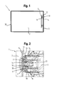
- FIG. 1 shows a schematic simplified sectional view of a refrigerator 1 according to a first embodiment.
- the refrigeration device 1 has a refrigerated goods chamber 2, in which an evaporator plate 5 of an evaporator is arranged.
- the evaporator plate 5 is arranged close to the wall in the refrigerated goods chamber 2.
- a closable opening 30 for access to the refrigerated goods 2 by a user against the rear wall 3 of the refrigerated goods 2 is arranged.
- the evaporator plate 5 thus runs at least in this embodiment Partially between the opening 30 and the rear wall 3 of the refrigerated goods 2.
- the distance of the evaporator plate 1 to the opening 30 is substantially smaller due to the near-wall arrangement to the rear wall 3 as the opening 30.
- the evaporator plate 5 is by means of two fasteners 10 on the rear wall. 3 appropriate.
- the fastening elements 10 each have a fastening part 12 which is constructed in two layers from a hard layer facing the evaporator plate 5 and a hard layer 14 attached to the rear wall 3.
- the evaporator plate 5 is bonded to the soft layer 13, which is vulcanized as a rubber coating on the hard layer 14 made of plastic.
- the hard layer 14 is screwed to the rear wall 3.
- the hard layer 14 allows a sufficient stability of the mounting of the evaporator plate 5.
- By the soft layer 13 a vibration-technical decoupling of the evaporator plate 5 is achieved by the rear wall 3.
- the transmission of vibrations or noises occurring at the evaporator circuit board 5, for example injection noise or noise, is prevented by the compressor via the rear wall 3 and the refrigeration device 1 to the environment.
- the noise emission behavior of the refrigeration device 1 can be improved.
- the one-piece construction of the fastening part 12 allows a reduction of the parts and thus the installation costs.
- FIG. 2 shows a schematic perspective sectional view of a section of the refrigerator 1 according to a second embodiment.
- the refrigerated goods 2 of the refrigerator 1 is shown.
- To the right of the evaporator plate 5 extends substantially in the vertical direction.
- the fastener 10 has again, as based on the simplified representation of Fig. 1 already stated, a soft layer 13 and a hard layer 14 arranged thereon.
- the fastening part 12 in this exemplary embodiment has a bore which runs through the soft layer 13 into the hard layer 14.
- a fastening bolt 16 is provided which passes through the hole 15 and a hole 7 in the evaporator board 5 and which holds the evaporator board 5 spaced apart from the hard layer 14 by the soft layer 13.
- the fastening bolt 16 a head 17 at its Schafft 18, with which the fastening bolt 15 is supported on the evaporator plate 5.
- Head 17 and make 18 thus keep the evaporator plate 5, the soft layer 13 and the hard Layer 14 of the fastener 10 together.
- the evaporator plate 5 has a recess 6, in which the head 17 is at least partially recessed. As a result, the head 17 does not protrude so far into the refrigerated goods chamber 2, so that stored refrigerated goods do not so easily stick to it.
- the fastening bolt 16 is designed as a Sp Dr Driet and has a projection 19, by means of which it is locked to the hard layer 14. During mating locking, the shank 18 of the fastening bolt 16 elastically rebounds so that the projection 19 can stop in a corresponding projection in the hard layer 14. This makes the connection easy and permanent to add. Due to the design of the fastening bolt 16 as the expansion rivet, the forces which can be absorbed by the fastening of the evaporator plate 5 are limited, so that the connection is more likely to be released than the evaporator plate 5 is damaged.
- the soft layer 13 extends between the shaft 18 of the fastening bolt 16 and the evaporator plate 5, that a radial contact of the shaft 18 is prevented with the evaporator plate 5. Thereby, the transmission of vibrations from the evaporator board 5 to the hard layer 14 is prevented because a bridge of the soft layer 13 passes therebetween.
Landscapes
- Engineering & Computer Science (AREA)
- Chemical & Material Sciences (AREA)
- Combustion & Propulsion (AREA)
- Physics & Mathematics (AREA)
- Mechanical Engineering (AREA)
- Thermal Sciences (AREA)
- General Engineering & Computer Science (AREA)
- Devices That Are Associated With Refrigeration Equipment (AREA)
Abstract
Description
- Die vorliegende Erfindung betrifft ein Kältegerät, insbesondere Haushaltskältegerät, mit einer Kühlgutkammer und einer beabstandet zur Rückwand der Kühlgutkammer in der Kühlgutkammer angeordneten Verdampferplatine und mindestens einem Befestigungselement mittels dem die Verdampferplatine an der Rückwand, angebracht ist.
- Verdampfer von Kältegeräten weisen verbreitet Verdampferplatinen zur Kühlung einer Kühlgutkammer des Kältegerätes auf, die zur Kühlung von Produkten, die in der Kühlgutkammer angeordnet werden, dient.
- Bei innen in der Kühlgutkammer liegenden Verdampferplatinen, welche eine beidseitig umströmte Verdampferoberfläche haben, werden höhere thermische Wirkungsgrade erzielt als mit hinter der Rückwand der Kühlgutkammer eingeschäumten Verdampferplatinen. Bekannt sind daher Lösungen bei denen die Verdampferplatine ca. 15-25 mm vor der Rückwand parallel zu dieser aufgehängt ist. Bei dieser Anordnung kann es jedoch zu einem erhöhten Geräuschniveau kommen, da die Verdampferplatine wie eine Art Membran wirkt. Dadurch werden sowohl Einspritzgeräusche, wie auch durch den Kompressor verursachte Geräusche an die Umgebung abgegeben.
- Vor diesem Hintergrund ist es eine Aufgabe der vorliegenden Erfindung, ein verbessertes Kältegerät, insbesondere Haushaltskältegerät, zu schaffen, das insbesondere in seinem Geräuschemissionsverhalten optimiert ist und kostengünstig herstellbar ist.
- Diese Aufgabe wird durch die Merkmale des unabhängigen Anspruchs 1 gelöst. Weitere vorteilhafte Ausgestaltungen sind in den Unteransprüchen angegeben.
- Die vorliegende Erfindung betrifft ein Kältegerät mit einer Kühlgutkammer und einer beabstandet zur Rückwand der Kühlgutkammer in der Kühlgutkammer angeordneten Verdampferplatine. Die Kühlgutkammer kann mittels des Kältegerätes auf eine niedrige Temperatur gekühlt werden, um darin Kühlgut, beispielsweise Lebensmittel, Arzneimittel oder dergleichen, aufzubewahren. Die Kühlgutkammer ist im Wesentlichen durch Wände zum Isolieren umgeben; wobei mindestens eine von einem Bediener zu öffnende Türe oder Klappe den Zugriff auf das Kühlgut ermöglicht. Die Wand gegenüber der Türe oder Klappe wird im Folgenden als Rückwand bezeichnet. Die im Kühlraum angeordnete Verdampferplatine dient der Abkühlung des Kühlraums. Für einen optimalen thermischen Wirkungsgrad ist die Verdampferplatine beidseitig umströmt. Um eine gute Anströmung beider Seiten der plattenförmigen Verdampferplatine zu erzielen, ist diese beabstandet und bevorzugt im Wesentlichen parallel zur Rückwand angeordnet. Der Abstand zwischen Rückwand und Verdampferplatine beträgt bevorzugt 15 bis 25 mm. Dieser Abstand hat sich bewährt, um zum Einen eine gute Anströmung auch der der Rückwand zugewandten Seite der Verdampferplatine zu erreichen und zum Anderen den Platz in der Kühlgutkammer, der zur Lagerung von Kühlgut zur Verfügung steht, zu optimieren. Ist der Abstand zu klein, wird die Anströmung der der Rückwand zugewandten Seite der Verdampferplatine aus strömungsmechanischen Gründen beeinträchtigt, was den thermischen Wirkungsgrad herabsetzt. Die Verdampferplatine ist mit mindestens einem Befestigungselement an der Rückwand angebracht. Das Befestigungselement weist ein mehrschichtiges, beispielsweise einstückiges Befestigungsteil auf, das mit einer elastischen weichen Schicht und einer harten Schicht gebildet ist, wobei die weiche Schicht an der Verdampferplatine und die harte Schicht an der Rückwand anliegt. Die harte Schicht ermöglicht eine ausreichende Stabilität der Anbringung der Verdampferplatine. Durch die weiche Schicht wird eine schwingungstechnische Entkopplung der Verdampferplatine von der Rückwand erreicht. Dadurch wird die Weitergabe von an der Verdampferplatine auftretenden Schwingungen bzw. Geräuschen, beispielsweise Einspritzgeräuschen oder Geräuschen durch den Kompressor über die Rückwand und das Kältegerät an die Umgebung verhindert. Dadurch kann das Geräuschemissionsverhalten des Kältegerätes verbessert werden. Die einstückige Bauweise des Befestigungsteils ermöglicht eine Reduzierung der Teile und damit der Montagekosten. Eine fehlerhafte Montage beispielsweise durch das Vergessen der Montage von elastischen Unterlagscheiben wird vermieden. Ferner wird die Anzahl der Trennfugen im Vergleich zu Lösungen beispielsweise mit elastischen Unterlegscheiben reduziert, was hygienische Vorteile mit sich bringt, da sich zwischen den Trennfugen Schmutz sammeln kann.
- Unter einem Kältegerät wird insbesondere ein Haushaltskältegerät verstanden, also ein Kältegerät das zur Haushaltsführung in Haushalten oder eventuell auch im Gastronomiebereich eingesetzt wird, und insbesondere dazu dient Lebensmittel und/oder Getränke in haushaltsüblichen Mengen bei bestimmten Temperaturen zu lagern, wie beispielsweise ein Kühlschrank, ein Gefrierschrank, eine Kühlgefrierkombination oder ein Weinlagerschrank.
- Gemäß einer Ausführungsform ist die weiche Schicht aus einem weichen Kunststoff insbesondere Gummi und die harte Schicht aus einem harten Kunststoff oder Metall gebildet. Ist die weiche Schicht als auch die harte Schicht aus Kunststoff gebildet, ist eine besonders kostengünstige Fertigung des Befestigungsteils des Befestigungselementes möglich. Als Spritzgussteil sind besonders große Freiheiten bei der Formgestaltung des Befestigungsteils möglich. Ferner lassen sich die beiden Schichten besonders gut und haltbar miteinander verbinden, wenn beide Schichten aus Kunststoff gebildet sind. Beispielsweise können die weiche Schicht und die harte Schicht dann gut miteinander verklebt werden. Wird die weiche Schicht aus einem Gummi gebildet, ist es auch möglich die weiche Schicht auf die harte Schicht aufzuvulkanisieren. Dadurch kann die weiche Schicht aus Gummi auf die harte Schicht beispielsweise aus Kunststoff kostengünstig und haltbar ohne zusätzliche Befestigungsteile aufgebracht werden.
- Gemäß einer Ausführungsform weist das Befestigungsteil ein Loch, beispielsweise eine Bohrung auf, die durch die weiche Schicht in oder durch die harte Schicht verläuft und es ist ein Befestigungsbolzen vorgesehen, der durch das Loch und ein Loch in der Verdampferplatine verläuft und der die Verdampferplatine beabstandet zu der harten Schicht oder der Rückwand hält.
- Gemäß einer Ausführungsform weist der Befestigungsbolzen einen Kopf an einem Schafft auf, mit dem sich der Befestigungsbolzen an der Verdampferplatine abstützt. Der Kopf verhindert dabei, dass sich die Verdampferplatine von der weichen Schicht entfernt. Die Verdampferplatine weist beispielsweise eine Vertiefung auf, in die der Kopf wenigstens teilweise versenkt ist. Dadurch steht der Kopf weniger weit über die Verdampferplatine hinaus. Das hat den Vorteil, dass sich weniger leicht Schmutz am Kopf des Befestigungsbolzens verfängt. Ferner wird die Reinigung der Kühlgutkammer erleichtert.
- Gemäß einer Ausführungsform ist der Befestigungsbolzen als Spreizniet ausgeführt und weist wenigstens einen Vorsprung auf, mittels dem er mit der harten Schicht oder der Rückwand verrastet. Beim fügenden Verrasten federt der Schaft des Befestigungsbolzens elastisch auf, so dass der Vorsprung in einem entsprechenden Vorsprung in der harten Schicht oder Rückwand Halt finden kann. Dadurch ist die Verbindung einfach und dauerhaft zu fügen. Durch die Gestaltung des Befestigungsbolzens als Spreizniet werden die durch die Befestigung der Verdampferplatine aufnehmbaren Kräfte begrenzt, so dass sich eher die Verbindung löst, als dass die Verdampferplatine beschädigt wird. Der Befestigungsbolzen kann dabei als Blindniet ausgeführt sein. Beim Blindnieten erfolgt dabei der Fügevorgang von der Seite der Verdampferplatine aus. Der Blindniet wird durch die Bohrung in der Verdampferplatine eingeführt. Der anschließende Nietvorgang führt zu einer Stauchung und somit zu einer Aufweitung des Niets im Bereich der harten Schicht oder der Rückwand und einer Fixierung dort. Dadurch kann die Anbringung der Verdampferplatine leicht aus der Kühlgutkammer heraus erfolgen.
- Gemäß einer Ausführungsform ist der Befestigungsbolzen mit der harten Schicht und/oder der weichen Schicht verklebt. Durch diese Maßnahme kann der Befestigungsbolzen besonders sicher und dauerhaft fixiert werden. Auf Grund der möglichen geringen Temperaturen in der Kühlgutkammer und der daraus folgenden geringen Elastizität des beispielsweise aus Kunststoff gefertigten Befestigungsbolzens kann diese als zusätzliche Maßnahme die Haltbarkeit beispielsweise einer Rastverbindung erhöhen.
- Gemäß einer Ausführungsform weist der Kopf des Befestigungsbolzens der Kühlgutkammer zugewandt, und damit der Verdampferplatte abgewandt, eine konvexe Wölbung auf. Dadurch bleibt in der Kühlgutkammer gelagertes Kühlgut nicht so leicht am Kopf hängen, was die Reinhaltung und Reinigung der Kühlgutkammer erleichtert.
- Gemäß einer Ausführungsform verläuft die weiche Schicht so zwischen dem Schaft des Befestigungsbolzens und der Verdampferplatine, dass eine radiale Berührung des Schaftes mit der Verdampferplatine verhindert wird. Dadurch wird die Übertragung von Schwingungen von der Verdampferplatine auf die harte Schicht verhindert, da eine Brücke aus der weichen Schicht dazwischen verläuft. Dadurch wird somit die Geräuschentwicklung verringert.
- Gemäß einer Ausführungsform ist die radiale Pressung zwischen dem Schaft und der weichen Schicht gering und beträgt bevorzugt weniger als 10 Newton/Quadratzentimeter. Durch diese geringe Anpressung wird die Übertragung von Schwingungen in eine zu stark zusammengepresste und damit verfestigte weiche Schicht und die Weiterleitung der Schwingungen beispielsweise in die Rückwand vermieden. Bevorzugt liegt daher der Kopf in axialer Richtung des Schafts auch nur locker an der weichen Schicht an, insbesondere, so, dass die resultierende Flächenpressung zwischen der Verdampferplatine und der weichen Schicht auch weniger als 10 Newton/Quadratzentimeter beträgt.
- Weitere mögliche Ausführungsformen der Erfindung umfassen auch nicht explizit genannte Kombinationen von zuvor oder im Folgenden bezüglich der Ausführungsbeispiele beschriebenen Merkmalen. Dabei wird der Fachmann auch Einzelaspekte als Verbesserungen oder Ergänzungen zu der jeweiligen Grundform des Kältegerätes hinzufügen.
- Weitere vorteilhafte Ausführungsformen der Erfindung werden unter Bezugnahme auf die beigelegten Figuren näher erläutert. Es zeigen:
- Figur 1:
- eine schematische vereinfachte Schnittdarstellung eines Kältegerätes gemäß einem ersten Ausführungsbeispiel; und
- Figur 2:
- eine schematische perspektivische Schnittdarstellung eines Ausschnitts des Kältegerätes gemäß einem zweiten Ausführungsbeispiel.
- In den Figuren sind gleiche oder funktionsgleiche Elemente mit denselben Bezugszeichen versehen, sofern nichts Anderes angegeben ist.
-
Figur 1 zeigt eine schematische vereinfachte Schnittdarstellung eines Kältegerätes 1 gemäß einem ersten Ausführungsbeispiel. Das Kältegerät 1 weist eine Kühlgutkammer 2 auf, in der eine Verdampferplatine 5 eines Verdampfers angeordnet ist. Die Verdampferplatine 5 ist in der Kühlgutkammer 2 wandnah angeordnet. Bei dieser Ausführungsform ist eine verschließbare Öffnung 30 für einen Zugang zur Kühlgutkammer 2 durch einen Benutzer gegenüber der Rückwand 3 der Kühlgutkammer 2 angeordnet. Die Verdampferplatine 5 verläuft somit bei diesem Ausführungsbeispiel wenigstens teilweise zwischen der Öffnung 30 und der Rückwand 3 der Kühlgutkammer 2. Der Abstand der Verdampferplatine 1 zur Öffnung 30 ist dabei auf Grund der wandnahen Anordnung zur Rückwand 3 wesentlich kleiner als zur Öffnung 30. Die Verdampferplatine 5 ist mittels zwei Befestigungselementen 10 an der Rückwand 3 angebracht. Die Befestigungselemente 10 weisen jeweils ein Befestigungsteil 12 auf, das zweischichtig aus einer harten der Verdampferplatine 5 zugewandten Schicht und einer an der Rückwand 3 angebrachten harten Schicht 14 aufgebaut ist. Bei diesem Ausführungsbeispiel ist die Verdampferplatine 5 mit der weichen Schicht 13 verklebt, die als Gummierung auf die harte Schicht 14 aus Kunststoff aufvulkanisiert ist. Die harte Schicht 14 ist an der Rückwand 3 angeschraubt. Die harte Schicht 14 ermöglicht eine ausreichende Stabilität der Anbringung der Verdampferplatine 5. Durch die weiche Schicht 13 wird eine schwingungstechnische Entkopplung der Verdampferplatine 5 von der Rückwand 3 erreicht. Dadurch wird die Weitergabe von an der Verdampferplatine 5 auftretenden Schwingungen bzw. Geräuschen, beispielsweise Einspritzgeräuschen oder Geräuschen durch den Kompressor über die Rückwand 3 und das Kältegerät 1 an die Umgebung verhindert. Dadurch kann das Geräuschemissionsverhalten des Kältegerätes 1 verbessert werden. Die einstückige Bauweise des Befestigungsteils 12 ermöglicht eine Reduzierung der Teile und damit der Montagekosten. -
Figur 2 zeigt eine schematische perspektivische Schnittdarstellung eines Ausschnitts des Kältegerätes 1 gemäß einem zweiten Ausführungsbeispiel. Links im Bild ist die Kühlgutkammer 2 des Kältegerätes 1 dargestellt. Rechts davon erstreckt sich die Verdampferplatine 5 im Wesentlichen in vertikaler Richtung. Mittels des Befestigungselementes 10 ist die Verdampferplatine 5 an der rechts im Bild dargestellten Rückwand 3 der Kühlgutkammer 2 befestigt. Das Befestigungselement 10 weist wieder, wie anhand der vereinfachten Darstellung vonFig. 1 schon ausgeführt, eine weiche Schicht 13 und eine daran angeordnete harte Schicht 14 auf. Das Befestigungsteil 12 weist bei diesem Ausführungsbeispiel eine Bohrung auf, die durch die weiche Schicht 13 in die harte Schicht 14 verläuft. Es ist ein Befestigungsbolzen 16 vorgesehen, der durch das Loch 15 und ein Loch 7 in der Verdampferplatine 5 verläuft und der die Verdampferplatine 5 durch die weiche Schicht 13 beabstandet zu der harten Schicht 14 hält. Dazu weist der Befestigungsbolzen 16 einen Kopf 17 an seinem Schafft 18 auf, mit dem sich der Befestigungsbolzen 15 an der Verdampferplatine 5 abstützt. Kopf 17 und Schafft 18 halten somit die Verdampferplatine 5, die weiche Schicht 13 und die harte Schicht 14 des Befestigungselementes 10 zusammen. Die Verdampferplatine 5 weist eine Vertiefung 6 auf, in die der Kopf 17 wenigstens teilweise versenkt ist. Dadurch steht der Kopf 17 nicht so weit in die Kühlgutkammer 2 vor, so dass gelagertes Kühlgut nicht so leicht daran hängen bleibt. Dem gleiche Zweck dient, dass der Kopf 17 eine der Kühlgutkammer 2 zugewandte konvexe Wölbung aufweist. Der Befestigungsbolzen 16 ist als Spreizniet ausgeführt und weist einen Vorsprung 19 auf, mittels dem er mit der harten Schicht 14 verrastet ist. Beim fügenden Verrasten federt der Schaft 18 des Befestigungsbolzens 16 elastisch auf, so dass der Vorsprung 19 in einem entsprechenden Vorsprung in der harten Schicht 14 halt finden kann. Dadurch ist die Verbindung einfach und dauerhaft zu fügen. Durch die Gestaltung des Befestigungsbolzens 16 als Spreizniet werden die durch die Befestigung der Verdampferplatine 5 aufnehmbaren Kräfte begrenzt, so dass sich eher die Verbindung löst als die Verdampferplatine 5 beschädigt wird. Bei diesem Ausführungsbeispiel verläuft die weiche Schicht 13 so zwischen dem Schaft 18 des Befestigungsbolzens 16 und der Verdampferplatine 5, dass eine radiale Berührung des Schaftes 18 mit der Verdampferplatine 5 verhindert wird. Dadurch wird die Übertragung von Schwingungen von der Verdampferplatine 5 auf die harte Schicht 14 verhindert, da eine Brücke aus der weichen Schicht 13 dazwischen verläuft. -
- 1
- Kältegerät
- 2
- Kühlgutkammer
- 3
- Rückwand
- 5
- Verdampferplatine
- 6
- Vertiefung
- 7
- Loch
- 10
- Befestigungselement
- 12
- Befestigungsteil
- 13
- weiche Schicht
- 14
- harte Schicht
- 15
- Loch
- 16
- Befestigungsbolzen
- 17
- Kopf
- 18
- Schaft
- 19
- Vorsprung
- 20
- Wölbung
- 30
- Öffnung
Claims (16)
- Kältegerät (1), insbesondere Haushaltskältegerät, mit einer Kühlgutkammer (2) und einer beabstandet zur Rückwand (3) der Kühlgutkammer (2) in der Kühlgutkammer (2) angeordneten Verdampferplatine (5) und mindestens einem Befestigungselement (10) mittels dem die Verdampferplatine (5) an der Rückwand (3), angebracht ist, dadurch gekennzeichnet, dass das Befestigungselement (10) ein mehrschichtiges Befestigungsteil (12) aufweist, das mit einer elastischen weichen Schicht (13) und einer harten Schicht (14) gebildet ist, und dass die weiche Schicht (13) an der Verdampferplatine (5) und die harte Schicht (14) an der Rückwand (3) anliegt.
- Kältegerät (1) nach Anspruch 1, dadurch gekennzeichnet, dass die weiche Schicht (13) aus einem weichen Kunststoff insbesondere Gummi und die harte Schicht aus einem harten Kunststoff oder Metall gebildet ist.
- Kältegerät (1) nach Anspruch 1 oder 2, dadurch gekennzeichnet, dass die weiche Schicht (13) und die harte Schicht (14) miteinander verklebt sind.
- Kältegerät (1) nach Anspruch 1 oder 2, dadurch gekennzeichnet, dass die weiche Schicht (13) auf die harte Schicht (14) aufvulkanisiert ist.
- Kältegerät (1) nach einem der vorhergehenden Ansprüche, dadurch gekennzeichnet, dass das Befestigungsteil (12) ein Loch (15), insbesondere eine Bohrung, aufweist, das durch die weiche Schicht (13) in oder durch die harte Schicht (14) verläuft und ein Befestigungsbolzen (16) vorgesehen ist, der durch das Loch (15) und ein Loch (7) in der Verdampferplatine (5) verläuft und der die Verdampferplatine (5) beabstandet zu der harten Schicht (14) oder der Rückwand (3) hält.
- Kältegerät (1) nach einem der vorhergehenden Ansprüche, dadurch gekennzeichnet, dass das Befestigungsteil (12) einstückig ist.
- Kältegerät (1) nach Anspruch 5, dadurch gekennzeichnet, dass der Befestigungsbolzen (16) einen Kopf (17) an einem Schafft (18) aufweist, mit dem sich der Befestigungsbolzen (15) an der Verdampferplatine (5) abstützt.
- Kältegerät (1) nach Anspruch 6, dadurch gekennzeichnet, dass die Verdampferplatine (5) eine Vertiefung (6) aufweist, in die der Kopf (17) wenigstens teilweise versenkt ist.
- Kältegerät (1) nach einem der Ansprüche 5 bis 7, dadurch gekennzeichnet, dass der Befestigungsbolzen (16) als Spreizniet ausgeführt ist und wenigstens einen Vorsprung (19) aufweist, mittels dem er mit der harten Schicht (14) oder der Rückwand (3) verrastet.
- Kältegerät (1) nach einem der Ansprüche 5 bis 8, dadurch gekennzeichnet, dass der Befestigungsbolzen (16) als Blindniet ausgeführt ist.
- Kältegerät (1) nach einem der Ansprüche 5 bis 9, dadurch gekennzeichnet, dass der Befestigungsbolzen (16) aus Kunststoff gebildet ist.
- Kältegerät (1) nach einem der Ansprüche 5 bis 10, dadurch gekennzeichnet, dass der Befestigungsbolzen (16) mit der harten Schicht (14) und/oder der weichen Schicht (13) verklebt ist.
- Kältegerät (1) nach einem der Ansprüche 6 bis 11, dadurch gekennzeichnet, dass der Kopf (17) des Befestigungsbolzens (16) der Kühlgutkammer (2) zugewandt, und damit der Verdampferplatte (5) abgewandt, eine konvexe Wölbung (20) aufweist.
- Kältegerät (1) nach einem der Ansprüche 5 bis 12, dadurch gekennzeichnet, dass die weiche Schicht (13) so zwischen dem Schaft (18) des Befestigungsbolzens (16) und der Verdampferplatine (5) verläuft, dass eine radiale Berührung des Schaftes (18) mit der Verdampferplatine (5) verhindert wird.
- Kältegerät (1) nach einem der Ansprüche 5 bis 10, dadurch gekennzeichnet, dass die radiale Pressung zwischen dem Schaft (18) und der weichen Schicht (13) gering ist, insbesondere weniger als 10 Newton/Quadratzentimeter beträgt.
- Kältegerät (1) nach einem der Ansprüche 6 bis 14, dadurch gekennzeichnet, dass der Kopf (17) in axialer Richtung des Schafts (18) nur locker an der Verdampferplatine (5) anliegt, insbesondere, so, dass die resultierende Flächenpressung zwischen der Verdampferplatine (5) und der weichen Schicht (13) weniger als 10 Newton/Quadratzentimeter beträgt.
Applications Claiming Priority (1)
| Application Number | Priority Date | Filing Date | Title |
|---|---|---|---|
| DE102011075322A DE102011075322A1 (de) | 2011-05-05 | 2011-05-05 | Kältegerät |
Publications (3)
| Publication Number | Publication Date |
|---|---|
| EP2520884A2 true EP2520884A2 (de) | 2012-11-07 |
| EP2520884A3 EP2520884A3 (de) | 2017-11-22 |
| EP2520884B1 EP2520884B1 (de) | 2020-07-08 |
Family
ID=46052610
Family Applications (1)
| Application Number | Title | Priority Date | Filing Date |
|---|---|---|---|
| EP12166365.2A Not-in-force EP2520884B1 (de) | 2011-05-05 | 2012-05-02 | Kältegerät |
Country Status (2)
| Country | Link |
|---|---|
| EP (1) | EP2520884B1 (de) |
| DE (1) | DE102011075322A1 (de) |
Family Cites Families (3)
| Publication number | Priority date | Publication date | Assignee | Title |
|---|---|---|---|---|
| DE20005803U1 (de) * | 2000-03-29 | 2001-08-02 | Liebherr-Hausgeräte GmbH, 88416 Ochsenhausen | Befestigungselement |
| BRPI0401588A (pt) * | 2004-04-14 | 2005-11-22 | Multibras Eletrodomesticos Sa | Elemento fixador de evaporador |
| DE102009002329A1 (de) * | 2009-04-09 | 2010-10-14 | BSH Bosch und Siemens Hausgeräte GmbH | Kältegerät mit Einbauteil |
-
2011
- 2011-05-05 DE DE102011075322A patent/DE102011075322A1/de not_active Withdrawn
-
2012
- 2012-05-02 EP EP12166365.2A patent/EP2520884B1/de not_active Not-in-force
Non-Patent Citations (1)
| Title |
|---|
| None |
Also Published As
| Publication number | Publication date |
|---|---|
| DE102011075322A1 (de) | 2012-11-08 |
| EP2520884B1 (de) | 2020-07-08 |
| EP2520884A3 (de) | 2017-11-22 |
Similar Documents
| Publication | Publication Date | Title |
|---|---|---|
| EP3262357B1 (de) | Kältegerät | |
| WO2015155025A1 (de) | Haushaltskältegerät umfassend einen verdichterfüsse aufweisenden verdichter | |
| WO2011101232A2 (de) | Kältegerät mit einer befestigungseinrichtung für einen verdichter und verfahren zur montage eines verdichters | |
| EP2906888B1 (de) | Kältegerät mit einbauteil | |
| DE102012218347A1 (de) | Lüftereinheit | |
| EP2457038B1 (de) | Kältegerät, insbesondere haushaltskältegerät mit einer befestigungsanordnung für einen verdichter | |
| EP2281156B1 (de) | Kältegerät mit einer umgebogenen verdampferfläche und verfahren zum montieren eines kältegeräts | |
| EP3578905A1 (de) | Kühlgerät mit einem befestigungsmechanismus für ein bauteil im nutzraum | |
| DE102011075322A1 (de) | Kältegerät | |
| DE102013215488A1 (de) | Kältegerät mit Seitenwandverflüssiger | |
| WO2018172087A1 (de) | Haushaltskältegerät mit einem türblatt und einem türabsteller | |
| EP4244554B1 (de) | Wandungsanordnung für ein kältegerät, kältegerät sowie verfahren zum zusammenbau einer wandungsanordnung | |
| DE102012209815A1 (de) | Kältegerät mit einer Tragschiene | |
| EP2743621B1 (de) | Kältegerät mit einem Fachboden | |
| EP1075635B1 (de) | Kältegerät | |
| EP2743620A2 (de) | Kältegerät mit einem Fachboden | |
| WO2018019580A1 (de) | Kältegerät mit einem verdunstungsbehälter | |
| WO2013120745A1 (de) | Kältegerät, insbesondere haushaltskältegerät, und verfahren zu dessen herstellung | |
| EP3760954A1 (de) | Haushaltsgerätevorrichtung | |
| DE102018201099A1 (de) | Haushaltsgerätevorrichtung | |
| EP2836776B1 (de) | Kältegerät mit einer lüftereinheit | |
| DE102016216302A1 (de) | Haushaltskältegerätevorrichtung | |
| DE102012210260A1 (de) | Kältegerät mit einem Bauteil | |
| EP4155634A1 (de) | Kältegerät, verdichterbaugruppe für ein kältegerät und verfahren zum montieren der verdichterbaugruppe | |
| EP4310422A1 (de) | Kältegerät und halter zum fixieren von funktionskomponenten eines kältemittelkreislaufs in einem maschinenraum eines kältegeräts und verfahren zur montage des halters an einer tragvorrichtung |
Legal Events
| Date | Code | Title | Description |
|---|---|---|---|
| PUAI | Public reference made under article 153(3) epc to a published international application that has entered the european phase |
Free format text: ORIGINAL CODE: 0009012 |
|
| AK | Designated contracting states |
Kind code of ref document: A2 Designated state(s): AL AT BE BG CH CY CZ DE DK EE ES FI FR GB GR HR HU IE IS IT LI LT LU LV MC MK MT NL NO PL PT RO RS SE SI SK SM TR |
|
| AX | Request for extension of the european patent |
Extension state: BA ME |
|
| RAP1 | Party data changed (applicant data changed or rights of an application transferred) |
Owner name: BSH HAUSGERAETE GMBH |
|
| PUAL | Search report despatched |
Free format text: ORIGINAL CODE: 0009013 |
|
| AK | Designated contracting states |
Kind code of ref document: A3 Designated state(s): AL AT BE BG CH CY CZ DE DK EE ES FI FR GB GR HR HU IE IS IT LI LT LU LV MC MK MT NL NO PL PT RO RS SE SI SK SM TR |
|
| AX | Request for extension of the european patent |
Extension state: BA ME |
|
| RIC1 | Information provided on ipc code assigned before grant |
Ipc: F25D 23/06 20060101ALI20171018BHEP Ipc: F25D 23/00 20060101AFI20171018BHEP |
|
| STAA | Information on the status of an ep patent application or granted ep patent |
Free format text: STATUS: REQUEST FOR EXAMINATION WAS MADE |
|
| 17P | Request for examination filed |
Effective date: 20180522 |
|
| RBV | Designated contracting states (corrected) |
Designated state(s): AL AT BE BG CH CY CZ DE DK EE ES FI FR GB GR HR HU IE IS IT LI LT LU LV MC MK MT NL NO PL PT RO RS SE SI SK SM TR |
|
| STAA | Information on the status of an ep patent application or granted ep patent |
Free format text: STATUS: EXAMINATION IS IN PROGRESS |
|
| 17Q | First examination report despatched |
Effective date: 20191014 |
|
| GRAP | Despatch of communication of intention to grant a patent |
Free format text: ORIGINAL CODE: EPIDOSNIGR1 |
|
| STAA | Information on the status of an ep patent application or granted ep patent |
Free format text: STATUS: GRANT OF PATENT IS INTENDED |
|
| INTG | Intention to grant announced |
Effective date: 20200131 |
|
| GRAS | Grant fee paid |
Free format text: ORIGINAL CODE: EPIDOSNIGR3 |
|
| GRAA | (expected) grant |
Free format text: ORIGINAL CODE: 0009210 |
|
| STAA | Information on the status of an ep patent application or granted ep patent |
Free format text: STATUS: THE PATENT HAS BEEN GRANTED |
|
| AK | Designated contracting states |
Kind code of ref document: B1 Designated state(s): AL AT BE BG CH CY CZ DE DK EE ES FI FR GB GR HR HU IE IS IT LI LT LU LV MC MK MT NL NO PL PT RO RS SE SI SK SM TR |
|
| REG | Reference to a national code |
Ref country code: GB Ref legal event code: FG4D Free format text: NOT ENGLISH |
|
| REG | Reference to a national code |
Ref country code: CH Ref legal event code: EP Ref country code: AT Ref legal event code: REF Ref document number: 1288894 Country of ref document: AT Kind code of ref document: T Effective date: 20200715 |
|
| REG | Reference to a national code |
Ref country code: DE Ref legal event code: R096 Ref document number: 502012016197 Country of ref document: DE |
|
| REG | Reference to a national code |
Ref country code: IE Ref legal event code: FG4D Free format text: LANGUAGE OF EP DOCUMENT: GERMAN |
|
| REG | Reference to a national code |
Ref country code: LT Ref legal event code: MG4D |
|
| REG | Reference to a national code |
Ref country code: NL Ref legal event code: MP Effective date: 20200708 |
|
| PG25 | Lapsed in a contracting state [announced via postgrant information from national office to epo] |
Ref country code: NO Free format text: LAPSE BECAUSE OF FAILURE TO SUBMIT A TRANSLATION OF THE DESCRIPTION OR TO PAY THE FEE WITHIN THE PRESCRIBED TIME-LIMIT Effective date: 20201008 Ref country code: SE Free format text: LAPSE BECAUSE OF FAILURE TO SUBMIT A TRANSLATION OF THE DESCRIPTION OR TO PAY THE FEE WITHIN THE PRESCRIBED TIME-LIMIT Effective date: 20200708 Ref country code: GR Free format text: LAPSE BECAUSE OF FAILURE TO SUBMIT A TRANSLATION OF THE DESCRIPTION OR TO PAY THE FEE WITHIN THE PRESCRIBED TIME-LIMIT Effective date: 20201009 Ref country code: FI Free format text: LAPSE BECAUSE OF FAILURE TO SUBMIT A TRANSLATION OF THE DESCRIPTION OR TO PAY THE FEE WITHIN THE PRESCRIBED TIME-LIMIT Effective date: 20200708 Ref country code: LT Free format text: LAPSE BECAUSE OF FAILURE TO SUBMIT A TRANSLATION OF THE DESCRIPTION OR TO PAY THE FEE WITHIN THE PRESCRIBED TIME-LIMIT Effective date: 20200708 Ref country code: HR Free format text: LAPSE BECAUSE OF FAILURE TO SUBMIT A TRANSLATION OF THE DESCRIPTION OR TO PAY THE FEE WITHIN THE PRESCRIBED TIME-LIMIT Effective date: 20200708 Ref country code: ES Free format text: LAPSE BECAUSE OF FAILURE TO SUBMIT A TRANSLATION OF THE DESCRIPTION OR TO PAY THE FEE WITHIN THE PRESCRIBED TIME-LIMIT Effective date: 20200708 Ref country code: PT Free format text: LAPSE BECAUSE OF FAILURE TO SUBMIT A TRANSLATION OF THE DESCRIPTION OR TO PAY THE FEE WITHIN THE PRESCRIBED TIME-LIMIT Effective date: 20201109 Ref country code: BG Free format text: LAPSE BECAUSE OF FAILURE TO SUBMIT A TRANSLATION OF THE DESCRIPTION OR TO PAY THE FEE WITHIN THE PRESCRIBED TIME-LIMIT Effective date: 20201008 |
|
| PG25 | Lapsed in a contracting state [announced via postgrant information from national office to epo] |
Ref country code: PL Free format text: LAPSE BECAUSE OF FAILURE TO SUBMIT A TRANSLATION OF THE DESCRIPTION OR TO PAY THE FEE WITHIN THE PRESCRIBED TIME-LIMIT Effective date: 20200708 Ref country code: RS Free format text: LAPSE BECAUSE OF FAILURE TO SUBMIT A TRANSLATION OF THE DESCRIPTION OR TO PAY THE FEE WITHIN THE PRESCRIBED TIME-LIMIT Effective date: 20200708 Ref country code: LV Free format text: LAPSE BECAUSE OF FAILURE TO SUBMIT A TRANSLATION OF THE DESCRIPTION OR TO PAY THE FEE WITHIN THE PRESCRIBED TIME-LIMIT Effective date: 20200708 Ref country code: IS Free format text: LAPSE BECAUSE OF FAILURE TO SUBMIT A TRANSLATION OF THE DESCRIPTION OR TO PAY THE FEE WITHIN THE PRESCRIBED TIME-LIMIT Effective date: 20201108 |
|
| PG25 | Lapsed in a contracting state [announced via postgrant information from national office to epo] |
Ref country code: NL Free format text: LAPSE BECAUSE OF FAILURE TO SUBMIT A TRANSLATION OF THE DESCRIPTION OR TO PAY THE FEE WITHIN THE PRESCRIBED TIME-LIMIT Effective date: 20200708 |
|
| REG | Reference to a national code |
Ref country code: DE Ref legal event code: R097 Ref document number: 502012016197 Country of ref document: DE |
|
| PG25 | Lapsed in a contracting state [announced via postgrant information from national office to epo] |
Ref country code: IT Free format text: LAPSE BECAUSE OF FAILURE TO SUBMIT A TRANSLATION OF THE DESCRIPTION OR TO PAY THE FEE WITHIN THE PRESCRIBED TIME-LIMIT Effective date: 20200708 Ref country code: CZ Free format text: LAPSE BECAUSE OF FAILURE TO SUBMIT A TRANSLATION OF THE DESCRIPTION OR TO PAY THE FEE WITHIN THE PRESCRIBED TIME-LIMIT Effective date: 20200708 Ref country code: EE Free format text: LAPSE BECAUSE OF FAILURE TO SUBMIT A TRANSLATION OF THE DESCRIPTION OR TO PAY THE FEE WITHIN THE PRESCRIBED TIME-LIMIT Effective date: 20200708 Ref country code: DK Free format text: LAPSE BECAUSE OF FAILURE TO SUBMIT A TRANSLATION OF THE DESCRIPTION OR TO PAY THE FEE WITHIN THE PRESCRIBED TIME-LIMIT Effective date: 20200708 Ref country code: RO Free format text: LAPSE BECAUSE OF FAILURE TO SUBMIT A TRANSLATION OF THE DESCRIPTION OR TO PAY THE FEE WITHIN THE PRESCRIBED TIME-LIMIT Effective date: 20200708 Ref country code: SM Free format text: LAPSE BECAUSE OF FAILURE TO SUBMIT A TRANSLATION OF THE DESCRIPTION OR TO PAY THE FEE WITHIN THE PRESCRIBED TIME-LIMIT Effective date: 20200708 |
|
| PLBE | No opposition filed within time limit |
Free format text: ORIGINAL CODE: 0009261 |
|
| STAA | Information on the status of an ep patent application or granted ep patent |
Free format text: STATUS: NO OPPOSITION FILED WITHIN TIME LIMIT |
|
| PG25 | Lapsed in a contracting state [announced via postgrant information from national office to epo] |
Ref country code: AL Free format text: LAPSE BECAUSE OF FAILURE TO SUBMIT A TRANSLATION OF THE DESCRIPTION OR TO PAY THE FEE WITHIN THE PRESCRIBED TIME-LIMIT Effective date: 20200708 |
|
| 26N | No opposition filed |
Effective date: 20210409 |
|
| PG25 | Lapsed in a contracting state [announced via postgrant information from national office to epo] |
Ref country code: SK Free format text: LAPSE BECAUSE OF FAILURE TO SUBMIT A TRANSLATION OF THE DESCRIPTION OR TO PAY THE FEE WITHIN THE PRESCRIBED TIME-LIMIT Effective date: 20200708 |
|
| PG25 | Lapsed in a contracting state [announced via postgrant information from national office to epo] |
Ref country code: SI Free format text: LAPSE BECAUSE OF FAILURE TO SUBMIT A TRANSLATION OF THE DESCRIPTION OR TO PAY THE FEE WITHIN THE PRESCRIBED TIME-LIMIT Effective date: 20200708 |
|
| REG | Reference to a national code |
Ref country code: CH Ref legal event code: PL |
|
| GBPC | Gb: european patent ceased through non-payment of renewal fee |
Effective date: 20210502 |
|
| PG25 | Lapsed in a contracting state [announced via postgrant information from national office to epo] |
Ref country code: CH Free format text: LAPSE BECAUSE OF NON-PAYMENT OF DUE FEES Effective date: 20210531 Ref country code: LU Free format text: LAPSE BECAUSE OF NON-PAYMENT OF DUE FEES Effective date: 20210502 Ref country code: MC Free format text: LAPSE BECAUSE OF FAILURE TO SUBMIT A TRANSLATION OF THE DESCRIPTION OR TO PAY THE FEE WITHIN THE PRESCRIBED TIME-LIMIT Effective date: 20200708 Ref country code: LI Free format text: LAPSE BECAUSE OF NON-PAYMENT OF DUE FEES Effective date: 20210531 |
|
| REG | Reference to a national code |
Ref country code: BE Ref legal event code: MM Effective date: 20210531 |
|
| PG25 | Lapsed in a contracting state [announced via postgrant information from national office to epo] |
Ref country code: IE Free format text: LAPSE BECAUSE OF NON-PAYMENT OF DUE FEES Effective date: 20210502 Ref country code: GB Free format text: LAPSE BECAUSE OF NON-PAYMENT OF DUE FEES Effective date: 20210502 |
|
| PG25 | Lapsed in a contracting state [announced via postgrant information from national office to epo] |
Ref country code: FR Free format text: LAPSE BECAUSE OF NON-PAYMENT OF DUE FEES Effective date: 20210531 |
|
| REG | Reference to a national code |
Ref country code: AT Ref legal event code: MM01 Ref document number: 1288894 Country of ref document: AT Kind code of ref document: T Effective date: 20210502 |
|
| PG25 | Lapsed in a contracting state [announced via postgrant information from national office to epo] |
Ref country code: BE Free format text: LAPSE BECAUSE OF NON-PAYMENT OF DUE FEES Effective date: 20210531 |
|
| PGFP | Annual fee paid to national office [announced via postgrant information from national office to epo] |
Ref country code: DE Payment date: 20220531 Year of fee payment: 11 |
|
| PG25 | Lapsed in a contracting state [announced via postgrant information from national office to epo] |
Ref country code: AT Free format text: LAPSE BECAUSE OF NON-PAYMENT OF DUE FEES Effective date: 20210502 |
|
| PG25 | Lapsed in a contracting state [announced via postgrant information from national office to epo] |
Ref country code: HU Free format text: LAPSE BECAUSE OF FAILURE TO SUBMIT A TRANSLATION OF THE DESCRIPTION OR TO PAY THE FEE WITHIN THE PRESCRIBED TIME-LIMIT; INVALID AB INITIO Effective date: 20120502 Ref country code: CY Free format text: LAPSE BECAUSE OF FAILURE TO SUBMIT A TRANSLATION OF THE DESCRIPTION OR TO PAY THE FEE WITHIN THE PRESCRIBED TIME-LIMIT Effective date: 20200708 |
|
| REG | Reference to a national code |
Ref country code: DE Ref legal event code: R119 Ref document number: 502012016197 Country of ref document: DE |
|
| PG25 | Lapsed in a contracting state [announced via postgrant information from national office to epo] |
Ref country code: MK Free format text: LAPSE BECAUSE OF FAILURE TO SUBMIT A TRANSLATION OF THE DESCRIPTION OR TO PAY THE FEE WITHIN THE PRESCRIBED TIME-LIMIT Effective date: 20200708 Ref country code: DE Free format text: LAPSE BECAUSE OF NON-PAYMENT OF DUE FEES Effective date: 20231201 |
|
| PG25 | Lapsed in a contracting state [announced via postgrant information from national office to epo] |
Ref country code: TR Free format text: LAPSE BECAUSE OF FAILURE TO SUBMIT A TRANSLATION OF THE DESCRIPTION OR TO PAY THE FEE WITHIN THE PRESCRIBED TIME-LIMIT Effective date: 20200708 |
|
| PG25 | Lapsed in a contracting state [announced via postgrant information from national office to epo] |
Ref country code: MT Free format text: LAPSE BECAUSE OF FAILURE TO SUBMIT A TRANSLATION OF THE DESCRIPTION OR TO PAY THE FEE WITHIN THE PRESCRIBED TIME-LIMIT Effective date: 20200708 |