EP2520788A2 - Method for operating a fuel injection system for a combustion engine - Google Patents
Method for operating a fuel injection system for a combustion engine Download PDFInfo
- Publication number
- EP2520788A2 EP2520788A2 EP12165871A EP12165871A EP2520788A2 EP 2520788 A2 EP2520788 A2 EP 2520788A2 EP 12165871 A EP12165871 A EP 12165871A EP 12165871 A EP12165871 A EP 12165871A EP 2520788 A2 EP2520788 A2 EP 2520788A2
- Authority
- EP
- European Patent Office
- Prior art keywords
- fuel
- pressure
- control
- injection valve
- determined
- Prior art date
- Legal status (The legal status is an assumption and is not a legal conclusion. Google has not performed a legal analysis and makes no representation as to the accuracy of the status listed.)
- Withdrawn
Links
Images


Classifications
-
- F—MECHANICAL ENGINEERING; LIGHTING; HEATING; WEAPONS; BLASTING
- F02—COMBUSTION ENGINES; HOT-GAS OR COMBUSTION-PRODUCT ENGINE PLANTS
- F02D—CONTROLLING COMBUSTION ENGINES
- F02D41/00—Electrical control of supply of combustible mixture or its constituents
- F02D41/30—Controlling fuel injection
- F02D41/38—Controlling fuel injection of the high pressure type
- F02D41/3809—Common rail control systems
-
- F—MECHANICAL ENGINEERING; LIGHTING; HEATING; WEAPONS; BLASTING
- F02—COMBUSTION ENGINES; HOT-GAS OR COMBUSTION-PRODUCT ENGINE PLANTS
- F02D—CONTROLLING COMBUSTION ENGINES
- F02D41/00—Electrical control of supply of combustible mixture or its constituents
- F02D41/22—Safety or indicating devices for abnormal conditions
- F02D41/222—Safety or indicating devices for abnormal conditions relating to the failure of sensors or parameter detection devices
- F02D2041/223—Diagnosis of fuel pressure sensors
-
- F—MECHANICAL ENGINEERING; LIGHTING; HEATING; WEAPONS; BLASTING
- F02—COMBUSTION ENGINES; HOT-GAS OR COMBUSTION-PRODUCT ENGINE PLANTS
- F02D—CONTROLLING COMBUSTION ENGINES
- F02D41/00—Electrical control of supply of combustible mixture or its constituents
- F02D41/24—Electrical control of supply of combustible mixture or its constituents characterised by the use of digital means
- F02D41/2406—Electrical control of supply of combustible mixture or its constituents characterised by the use of digital means using essentially read only memories
- F02D41/2425—Particular ways of programming the data
- F02D41/2429—Methods of calibrating or learning
- F02D41/2438—Active learning methods
-
- F—MECHANICAL ENGINEERING; LIGHTING; HEATING; WEAPONS; BLASTING
- F02—COMBUSTION ENGINES; HOT-GAS OR COMBUSTION-PRODUCT ENGINE PLANTS
- F02D—CONTROLLING COMBUSTION ENGINES
- F02D41/00—Electrical control of supply of combustible mixture or its constituents
- F02D41/24—Electrical control of supply of combustible mixture or its constituents characterised by the use of digital means
- F02D41/2406—Electrical control of supply of combustible mixture or its constituents characterised by the use of digital means using essentially read only memories
- F02D41/2425—Particular ways of programming the data
- F02D41/2429—Methods of calibrating or learning
- F02D41/2451—Methods of calibrating or learning characterised by what is learned or calibrated
- F02D41/2464—Characteristics of actuators
- F02D41/2467—Characteristics of actuators for injectors
- F02D41/247—Behaviour for small quantities
Definitions
- the invention relates to a method according to the preamble of claim 1, and a computer program and a control and / or regulating device according to the independent claims.
- the invention relates to a method for operating a fuel injection system of an internal combustion engine, provided in the pressurized fuel in a pressure accumulator and a present in the pressure accumulator fuel pressure is controlled by means of a pressure control.
- a pressure control According to the invention, at least one withdrawal of fuel from the pressure accumulator takes place in a first measurement interval, and in a second measurement interval, no such removal of fuel from the pressure accumulator takes place.
- an operating variable of the pressure control is determined. By means of the operating variable, it is possible to determine a rate of the fuel respectively withdrawn from the pressure accumulator.
- the "rate” of the fuel is understood to mean the quotient of an amount of fuel (or control quantity) withdrawn or supplied to the accumulator and an associated time interval.
- the amount of fuel taken during the first measuring interval is determined in the at least one sampling from a difference of the determined operating variables of the pressure control.
- the difference characterizes the respectively withdrawn rate of the fuel.
- the first and second measurement intervals are arranged adjacent to one another in terms of time.
- the measurement intervals follow very briefly or even directly on each other, and have an equal duration.
- a specific order of the two measurement intervals is not required, that is, the second measurement interval may be behind the time or before the first measurement interval.
- the first or the second measurement interval comprise a duty cycle of the internal combustion engine or a part of a working cycle or several working cycles. It is not necessary that fuel is injected into the combustion chamber of the internal combustion engine during the measurement intervals, as will be explained below.
- the inventive method has the advantage that a pressure sensor of a pressure control in a fuel injection system of an internal combustion engine can be monitored and quantitatively evaluated. This generally requires no additional components or components. The process can be carried out comparatively accurately and with long-term stability.
- the at least one removal of fuel takes place by a servo valve of an injection valve of the internal combustion engine is controlled such that a control amount of the fuel is removed, in which the injection valve is not already injecting fuel into a combustion chamber of the internal combustion engine.
- the injection valve is driven so short that the servo valve is indeed actuated, but for example, a cooperating with an outlet opening (injector) of the injector valve needle does not lift off its valve seat ("blank shot").
- blade shot a cooperating with an outlet opening (injector) of the injector valve needle does not lift off its valve seat
- the amount of fuel required to briefly actuate the servo valve is fed into an injector return, thereby reducing the pressure in the pressure accumulator by a corresponding amount.
- a defined additional amount of fuel is removed from the accumulator via the described control of the injection valve, that is, a control of the injector actuating actuator, which is compensated quickly by means of the pressure control.
- leakage of the injection valve which, like the control quantity withdrawn according to the invention, is conducted into the injector return, results in removal of fuel from the pressure accumulator. This is continuously compensated by the pressure control.
- the leaks are comparatively strongly dependent on a fuel pressure and on the fuel temperature.
- the leaks can over the life of the injector, that is, these generally become larger with time.
- the respective control amounts are substantially dependent on the fuel pressure and the duration of the drive. Further, there may be little dependence of the control amounts on the fuel temperature and the type of fuel.
- control quantities do not or only insignificantly depend on the aging of the injection valve.
- the control quantities of the fuel thus depend essentially solely on the fuel pressure.
- the pressure sensor can therefore be quantitatively monitored, wherein the leaks in the first and the second measuring interval are the same and thus do not influence the difference of the determined operating variables.
- An embodiment of the invention provides that one or the servo valve of one or the injection valve of the internal combustion engine is repeatedly actuated in the first measuring interval for the removal of a control amount, wherein the control preferably takes place periodically.
- the majority of the extracted control amounts in the sum of the extracted fuel amount larger, whereby the accuracy of the method can be improved.
- the periodic control also simplifies the process.
- Carrying out the method is simplified and improved when the method is carried out in an operating mode of the internal combustion engine in which usually no injection of fuel into a combustion chamber of the internal combustion engine is provided, in particular in a coasting operation and / or a gas exchange phase.
- possible interference can be minimized and the operating conditions of the internal combustion engine can be reproduced particularly well during the measurement intervals.
- the gas exchange phase it is also possible to carry out the method in a load operation of the internal combustion engine.
- the removal of the control amount in the first measurement interval is carried out with a constant rate as possible, for example by means of the above-described periodic control.
- the state of the pressure sensor is closed by one of the removal rate of the fuel dependent operating variable, for example, a manipulated variable or a variable characterizing the manipulated variable size of the pressure control is determined.
- a defined quantity or rate of the fuel is additionally taken from the pressure accumulator, and not in a second case (second measuring interval).
- the injection valve is electrically actuated in a suitable manner in the first measuring interval, and not actuated in the second measuring interval, for example.
- the remaining operating conditions of the fuel injection system should be comparable in the first and second measurement intervals.
- the fuel pressure in the pressure accumulator is regulated as constantly as possible to the desired pressure value by means of the pressure control.
- the pressure control adjusts the manipulated variable appropriately. Because a larger rate of fuel is withdrawn from the accumulator in the first measurement interval than in the second measurement interval, the values of the operating quantity are correspondingly different.
- the control amount for a single operation of the servo valve is relatively independent of aging in conventional embodiments of injectors.
- a likewise substantially age-independent removal rate of the fuel results.
- the resulting difference therefore depends essentially on the fuel pressure and the withdrawal rate.
- the change in the operating variable or manipulated variable of the pressure control compared to the first to the second measurement interval is thus a relatively accurate measure of the nachzu carende in the pressure accumulator rate of the fuel.
- the pressure sensor indicates too high a fuel pressure of the accumulator, that is, the actual fuel pressure is smaller.
- the condition of the pressure sensor can be quantitatively evaluated and its function can be made plausible.
- the operating variable of the pressure control is determined at different fuel pressures and / or at different fuel temperatures and / or different fuel types and / or with different drive durations for the injection valve or the servo valve of the injection valve.
- these parameters are recorded or stored with.
- the storage can be done for example by means of a table and / or a map in a data memory of the control and / or regulating device. Thereby, a comparison of the respective control amounts to a new state of the fuel injection system in dependence of these parameters can take place and the accuracy of the method can thus be improved.
- a count number (for example 1 to 4 in a four-cylinder engine) of the injection valve can be determined as a parameter and used for the method.
- a count number for example 1 to 4 in a four-cylinder engine
- the injector may be manufactured by measuring patterns of the injector on a hydraulic test bench.
- the servo valve of the injection valve is controlled such that a control amount of the fuel is taken, in which the injection valve is not already settling fuel, and wherein the withdrawn control amount determined and the control amount characterizing size and / or a withdrawal rate of the fuel and / or a difference in the operating variable between the first and the second measuring interval as a function of a fuel pressure and / or a fuel temperature and / or a fuel grade and / or a Control period for the injection valve or the servo valve of the injection valve is stored in a map.
- the control quantities thus determined on the patterns can be stored in the respective control and / or regulating device of the internal combustion engine as a function of the parameters mentioned for a series of injection valves. As a result, in a new state of the internal combustion engine or the fuel injection system, a determination of the control amount is no longer required, which costs can be saved.
- the method according to the invention is carried out at least partially by means of a computer program which is stored on the control and / or regulating device of the internal combustion engine.
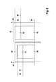
- FIG. 1 an internal combustion engine 1 of a motor vehicle is shown, in which a piston 2 in a cylinder 3 back and forth is movable.
- the cylinder 3 is provided with a combustion chamber 4 which is delimited inter alia by the piston 2, an inlet valve 5 and an outlet valve 6.
- an intake valve 5 With the intake valve 5, an intake pipe 7 and with the exhaust valve 6, an exhaust pipe 8 is coupled.
- the injection valve 9 comprises a - in the drawing of FIG. 1 not shown - servo valve, which can be actuated by an actuator 18. With a sufficient drive duration of the servo valve, fuel can be injected into the combustion chamber 4. With the spark plug 10, the fuel in the combustion chamber 4 can be ignited.
- a fuel injection system of the internal combustion engine 1 is designated by the reference numeral 100.
- a rotatable throttle valve 11 is housed, via which the intake pipe 7 air can be supplied.
- the amount of air supplied is dependent on the angular position of the throttle valve 11.
- a catalyst 12 is housed, which serves to purify the exhaust gases resulting from the combustion of the fuel.
- a low-pressure line 21 supplies fuel to a metering device 22 and to a high-pressure pump 23 coupled to the metering device 22.
- the high-pressure pump 23 is a - not visible in the drawing - electric and / or mechanical fuel pump, which is adapted to promote fuel with a respectively required pressure.
- the high-pressure pump 23 conveys the fuel by means of a supply line 24 into an accumulator 13.
- the injection valve 9 is connected via a pressure line 20 to the pressure accumulator 13.
- the injection valves 9 of the remaining (not shown) cylinder 3 of the internal combustion engine 1 are connected to the pressure accumulator 13; However, this is in the drawing of FIG. 1 indicated only by means of short vertical lines on the pressure accumulator 13.
- a pressure sensor 14 is arranged on the pressure accumulator 13, with which the pressure in the pressure accumulator 13 can be measured. This pressure is that pressure which is exerted on the fuel and with which therefore the fuel can be injected via the injection valve 9 into the combustion chamber 4 of the internal combustion engine 1.
- the fuel injection system 100 may also have a pressure regulating valve 14 a, which is designed to remove fuel from the pressure accumulator 13.
- a control and / or regulating device 15 in the upper right portion of the drawing according to FIG. 1 is acted upon by input signals 16, which represent measured by sensors operating variables of the internal combustion engine 1.
- the control and / or regulating device 15 is connected to the pressure sensor 14, an air mass sensor in the intake pipe 7, a lambda sensor in the exhaust pipe 8, a speed sensor and the like.
- the control and / or regulating device 15 generates output signals 17 with which the behavior of the internal combustion engine 1 can be influenced via actuators or actuators.
- the control and / or regulating device 15 is connected to the actuator 18 of the injection valve 9, the spark plug 10, the throttle valve 11, the pressure regulating valve 14 a and the like, and generates the signals required for their control.
- the control and / or regulating device 15 comprises a computer program 26 and a map 28.
- control and / or regulating device 15 is provided to control and / or regulate operating variables of the internal combustion engine 1.
- the fuel mass injected from the injection valve 9 into the combustion chamber 4 is controlled and / or regulated by the control and / or regulating device 15 as a function of a desired torque of the internal combustion engine 1 taking into account low fuel consumption and / or low pollutant development.
- fuel is conveyed into the pressure accumulator 13.
- This fuel is injected via the injection valves 9 of the individual cylinders 3 into the associated combustion chambers 4.
- burns are generated in the combustion chambers 4, through which the piston 2 are set in a reciprocating motion. These movements are transmitted to a crankshaft, not shown, and exert on this a torque.
- a current fuel pressure in the pressure accumulator 13 is determined.
- the metering device 22 is controlled by the control and / or regulating device 15 such that a respectively required fuel pressure in the pressure accumulator 13 can be kept as constant as possible.
- the pressure regulating valve 14a can also be actuated in a manner known per se in order to influence the fuel pressure in the pressure accumulator 13.
- the pressure regulating valve 14a can be assigned its own manipulated variable (comparable to the manipulated variable 25 of the metering device 22).
- the fuel pressure, the fuel temperature, and the fuel grade are taken into consideration as parameters.
- FIG. 2 2 shows a bar graph showing two aging states of the fuel injection system 100.
- a bar graph 30 left in the drawing describes a new state of the fuel injection system 100 and the injector 9.
- a right-hand bar diagram 32 in the drawing describes a state of the fuel injection system 100 and the injector 9, respectively operating time.
- Perpendicular to an abscissa 34 flow rates 36 of the fuel are applied, which in the present case are caused by leaks 38 and 40 on the one hand, and control amounts 42 and 44 of the injection valve 9 on the other hand.
- horizontal dashed lines indicate respectively a first flow 46 and 48, and a second flow 50 and 52, respectively.
- first flow rates 46 and 48 of the respective leakage 38 and 40 of the Injector 9 correspond to the first flow rates 46 and 48 of the respective leakage 38 and 40 of the Injector 9, and the second flow rates 50 and 52 of the respective leakage 38 and 40 plus the respective control amount 42 and 44th
- the control quantities 42 and 44 are the same. Therefore, the control amounts 42 and 44, respectively, are used to calculate in a first measurement interval 60 (see the following Figures 3 and 4 ) to allow a defined removal of fuel from the pressure accumulator 13. In a second measurement interval 62 (see the following Figures 3 and 4 ), however, no control amounts 42 and 44 are removed from the pressure accumulator 13. In both measuring intervals 60 and 62, however, there is a removal of fuel from the pressure accumulator 13 as a result of the leaks 38 and 40. By means of a subtraction of each taken in the first and the second measuring interval 60 and 62 amount of fuel can on the respective control amount 42 and 44 are closed. It can be concluded that the state of the pressure sensor 14.
- control quantity 44 determined according to a specific operating time deviates from the control quantity 42 determined in the new state, it is assumed according to the invention that the reason for this is an incorrectly regulated fuel pressure in the pressure accumulator 13 because of the assumed good reproducibility of the control quantities 42 and 44 ,
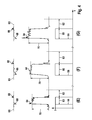
- FIG. 3 shows a first set of diagrams (A) to (D) over a time t entered on the abscissa.
- drive signals 58 are shown, which each define a first measurement interval 60 by an amplitude "1".
- the amplitude "0" defines a second measurement interval 62 for each first measurement interval 60, which immediately adjoins the first measurement interval 60.
- a respective duration of the first measurement intervals 60 in the diagrams (A) to (D) is different.
- the second measuring intervals 62 each have the same duration as the associated first measuring intervals 60.
- the first measurement intervals 60-and correspondingly the second measurement intervals 62-can also have the same duration.
- the method according to the invention can optionally be simplified and the accuracy increased.
- an operating variable 64 of the pressure control 19 of the fuel injection system 100 is entered in each case.
- the operating variable 64 characterizes a rate of the fuel taken out of the pressure accumulator 13.
- a respective associated pressure setpoint 66 is entered, which represents a parameter.
- a fuel pressure 68 is regulated in response to the pressure command 66.
- the curves shown in the diagrams (A) to (D) in the middle and the upper part have a vertical offset from each other for the sake of drawing.
- the pressure setpoint 66 increases stepwise from diagram (A) to diagram (D), but the associated lines or curves in the drawing show an approximately equal vertical dimension.
- the operating variables 64 of the respective second measuring intervals 62 are compared vertically to each other in order to allow a better comparison to the first measuring intervals 60.
- a plurality of withdrawals of fuel from the pressure accumulator 13 takes place periodically.
- the actuator 18 of the injection valve 9 is actuated so rapidly in each individual withdrawal that the injection valve 9 does not already inject fuel into the combustion chamber 4 of the internal combustion engine 1.
- each of a tax amount of Fuel for driving a servo valve of the injection valve 9 is removed from the pressure accumulator 13 and then fed back to the fuel injection system 100 via a return.
- no contribution is made to a torque of the internal combustion engine 1.
- the servo valve In the second measurement interval 62, no such removal of fuel occurs, that is, the servo valve is not actuated to remove a control amount of the fuel.
- the remaining operating conditions of the internal combustion engine 1 in the second measuring interval 62 should be as similar as possible to the operating conditions during the first measuring interval 60.
- the first and second measurement intervals 60 and 62 therefore follow one another directly.
- the additional fuel quantity taken during the first measuring interval 60 can be determined during the at least one take-off.
- the difference 70 is formed from average values of the operating quantities 64 during the first measuring interval 60 and the second measuring interval 62 in order to increase the accuracy of the method.
- a specific sequence of the first measurement interval 60 and of the second measurement interval 62 is not required, that is to say that in the diagrams (A) to (D) the "second" measurement interval 62 may also be arranged temporally before the associated first measurement interval 60.
- the inventive method is particularly simple and accurate to carry out when it is performed in an operating mode of the internal combustion engine 1, in which usually no injection of fuel is provided in the combustion chamber 4 of the internal combustion engine 1. For example, this can be done in a coasting operation of the internal combustion engine 1, in which no fuel is injected for a comparatively long period of time. However, it is also possible to carry out the process in a gas exchange phase during one or more operating cycles of the internal combustion engine 1.
- FIG. 4 shows a second set of diagrams (E) to (G) over time t, similar to the four diagrams (A) to (D) of FIG. 3 ,
- the FIG. 4 is thus one Continuation of the presentation of FIG. 3 , For the details of the drawing applies to the FIG. 3 The same.
- the rate (operating variable 64) of the fuel removed from the pressure accumulator 13 is greater during the respective first measuring intervals 60 than during the respective second measuring intervals 62. This is due to the control quantities 42 and 44 taken during the first measuring intervals 60. For both measuring intervals 60 and 62, however, a leakage 38 or 40 of the injection valve 9 is approximately equal. Furthermore, it can be seen that the difference 70 progressively increases in the diagrams (A) to (G) corresponding to the respective higher desired pressure value 66 or fuel pressure 68. It follows that the fuel pressure 68 represents a parameter in the determination of the control amount 42 and 44, respectively.
Abstract
Description
Die Erfindung betrifft ein Verfahren nach dem Oberbegriff des Anspruchs 1, sowie ein Computerprogramm und eine Steuer- und/oder Regeleinrichtung nach den nebengeordneten Patentansprüchen.The invention relates to a method according to the preamble of claim 1, and a computer program and a control and / or regulating device according to the independent claims.
Vom Markt her bekannt sind Einspritzventile von Brennkraftmaschinen, welche über ein so genanntes "Servoventil" betätigt werden, welches elektrisch angesteuert wird. Bei Betätigung des Servoventils wird ein Kraftstoffdruck in einem Steuerraum des Einspritzventils abgesenkt, wobei Kraftstoff über hydraulische Drosseln in einen Injektor-Rücklauf abgeführt wird. Mittels der so gebildeten Druckdifferenz kann eine Einspritzdüse geöffnet und Kraftstoff in einen Brennraum der Brennkraftmaschine eingespritzt werden.From the market known injection valves of internal combustion engines, which are actuated by a so-called "servo valve", which is electrically controlled. Upon actuation of the servo valve, a fuel pressure in a control chamber of the injection valve is lowered, wherein fuel is discharged via hydraulic throttles in an injector return. By means of the pressure difference thus formed, an injection nozzle can be opened and fuel injected into a combustion chamber of the internal combustion engine.
Damit der hydraulische Druck in einem das Einspritzventil versorgenden Druckspeicher (Kraftstoffspeicher, "Rail") nicht abnimmt, muss Kraftstoff in den Druckspeicher nachgefördert werden. Diese Nachförderung erfolgt mittels einer Druckregelung, wobei mittels eines Drucksensors ("Raildrucksensor") ein aktueller Kraftstoffdruck ermittelt wird. Dadurch kann mittels einer Zumesseinrichtung eine entsprechende Menge an Kraftstoff in den Druckspeicher nachgefördert werden.So that the hydraulic pressure in a pressure accumulator supplying the injection valve (fuel storage, "rail") does not decrease, fuel must be fed into the pressure accumulator. This Nachförderung carried out by means of a pressure control, wherein by means of a pressure sensor ("rail pressure sensor"), a current fuel pressure is determined. As a result, by means of a metering device, a corresponding amount of fuel can be conveyed to the pressure accumulator.
Das der Erfindung zugrunde liegende Problem wird durch ein Verfahren nach Anspruch 1 sowie durch ein Computerprogramm und eine Steuer- und/oder Regeleinrichtung nach den nebengeordneten Ansprüchen gelöst. Vorteilhafte Weiterbildungen sind in den Unteransprüchen angegeben.The problem underlying the invention is achieved by a method according to claim 1 and by a computer program and a control and / or regulating device according to the independent claims. Advantageous developments are specified in the subclaims.
Die Erfindung betrifft ein Verfahren zum Betreiben eines Kraftstoffeinspritzsystems einer Brennkraftmaschine, bei dem unter Druck stehender Kraftstoff in einem Druckspeicher bereit gestellt und ein in dem Druckspeicher vorliegender Kraftstoffdruck mittels einer Druckregelung geregelt wird. Erfindungsgemäß erfolgt in einem ersten Messintervall mindestens eine Entnahme von Kraftstoff aus dem Druckspeicher, und in einem zweiten Messintervall erfolgt keine derartige Entnahme von Kraftstoff aus dem Druckspeicher. In dem ersten und in dem zweiten Messintervall wird jeweils eine Betriebsgröße der Druckregelung ermittelt. Mittels der Betriebsgröße kann eine Rate des aus dem Druckspeicher jeweils entnommenen Kraftstoffs ermittelt werden.The invention relates to a method for operating a fuel injection system of an internal combustion engine, provided in the pressurized fuel in a pressure accumulator and a present in the pressure accumulator fuel pressure is controlled by means of a pressure control. According to the invention, at least one withdrawal of fuel from the pressure accumulator takes place in a first measurement interval, and in a second measurement interval, no such removal of fuel from the pressure accumulator takes place. In the first and in the second measuring interval in each case an operating variable of the pressure control is determined. By means of the operating variable, it is possible to determine a rate of the fuel respectively withdrawn from the pressure accumulator.
Unter der "Rate" des Kraftstoffs wird der Quotient aus einer dem Druckspeicher entnommenen bzw. zugeführten Kraftstoffmenge (bzw. Steuermenge) und einem zugehörigen Zeitintervall verstanden.The "rate" of the fuel is understood to mean the quotient of an amount of fuel (or control quantity) withdrawn or supplied to the accumulator and an associated time interval.
Besonders bevorzugt wird aus einer Differenz der ermittelten Betriebsgrößen der Druckregelung die während des ersten Messintervalls entnommene Kraftstoffmenge bei der mindestens einen Entnahme ermittelt. Die Differenz charakterisiert die jeweils entnommene Rate des Kraftstoffs. Durch die beschriebene Differenzbildung kann die in dem ersten Messintervall entnommene Steuermenge vergleichsweise genau ermittelt werden.Particularly preferably, the amount of fuel taken during the first measuring interval is determined in the at least one sampling from a difference of the determined operating variables of the pressure control. The difference characterizes the respectively withdrawn rate of the fuel. By means of the difference formation described, the control quantity taken in the first measuring interval can be determined comparatively accurately.
Von Vorteil ist es, wenn das erste und das zweite Messintervall zeitlich benachbart angeordnet sind. Vorzugsweise folgen die Messintervalle sehr kurz oder sogar unmittelbar aufeinander, und weisen eine gleiche Dauer auf. Eine bestimmte Reihenfolge der beiden Messintervalle ist dabei nicht erforderlich, das heißt, das zweite Messintervall kann zeitlich hinter oder vor dem ersten Messintervall liegen. Weiterhin kann das erste bzw. das zweite Messintervall einen Arbeitszyklus der Brennkraftmaschine oder einen Teil eines Arbeitszyklus oder mehrere Arbeitszyklen umfassen. Dabei ist es nicht erforderlich, dass während der Messintervalle Kraftstoff in den Brennraum der Brennkraftmaschine eingespritzt wird, wie weiter unten noch erläutert werden wird.It is advantageous if the first and second measurement intervals are arranged adjacent to one another in terms of time. Preferably, the measurement intervals follow very briefly or even directly on each other, and have an equal duration. A specific order of the two measurement intervals is not required, that is, the second measurement interval may be behind the time or before the first measurement interval. Furthermore, the first or the second measurement interval comprise a duty cycle of the internal combustion engine or a part of a working cycle or several working cycles. It is not necessary that fuel is injected into the combustion chamber of the internal combustion engine during the measurement intervals, as will be explained below.
Das erfindungsgemäße Verfahren weist den Vorteil auf, dass ein Drucksensor einer Druckregelung in einem Kraftstoffeinspritzsystem einer Brennkraftmaschine überwacht und quantitativ bewertet werden kann. Dazu sind im Allgemeinen keine zusätzlichen Bauelemente oder Komponenten erforderlich. Das Verfahren kann vergleichsweise genau und langzeitstabil durchgeführt werden.The inventive method has the advantage that a pressure sensor of a pressure control in a fuel injection system of an internal combustion engine can be monitored and quantitatively evaluated. This generally requires no additional components or components. The process can be carried out comparatively accurately and with long-term stability.
Insbesondere ist vorgesehen, dass die mindestens eine Entnahme von Kraftstoff erfolgt, indem ein Servoventil eines Einspritzventils der Brennkraftmaschine derart angesteuert wird, dass eine Steuermenge des Kraftstoffs entnommen wird, bei welcher das Einspritzventil nicht bereits Kraftstoff in einen Brennraum der Brennkraftmaschine einspritzt. Dabei wird das Einspritzventil so kurz angesteuert, dass das Servoventil zwar betätigt wird, jedoch beispielsweise eine mit einer Auslassöffnung (Einspritzdüse) des Einspritzventils zusammenwirkende Ventilnadel nicht von ihrem Ventilsitz abhebt ("Blank-Shot"). Somit wird einerseits noch kein Kraftstoff in den Brennraum der Brennkraftmaschine eingespritzt. Andererseits wird die zur kurzen Betätigung des Servoventils erforderliche Steuermenge ("Blank-Shot-Menge") des Kraftstoffs in einen Injektor-Rücklauf geführt, und dadurch der Druck in dem Druckspeicher jeweils um ein entsprechendes Maß gesenkt. Somit wird über die beschriebene Ansteuerung des Einspritzventils, das heißt, einer Ansteuerung eines das Einspritzventil betätigenden Aktors, eine definierte zusätzliche Kraftstoffmenge aus dem Druckspeicher entnommen, welche mittels der Druckregelung schnell kompensiert wird.In particular, it is provided that the at least one removal of fuel takes place by a servo valve of an injection valve of the internal combustion engine is controlled such that a control amount of the fuel is removed, in which the injection valve is not already injecting fuel into a combustion chamber of the internal combustion engine. In this case, the injection valve is driven so short that the servo valve is indeed actuated, but for example, a cooperating with an outlet opening (injector) of the injector valve needle does not lift off its valve seat ("blank shot"). Thus, on the one hand no fuel is injected into the combustion chamber of the internal combustion engine. On the other hand, the amount of fuel required to briefly actuate the servo valve is fed into an injector return, thereby reducing the pressure in the pressure accumulator by a corresponding amount. Thus, a defined additional amount of fuel is removed from the accumulator via the described control of the injection valve, that is, a control of the injector actuating actuator, which is compensated quickly by means of the pressure control.
Außer den im Betrieb der Brennkraftmaschine eingespritzten Kraftstoffmengen ergibt sich durch Leckagen des Einspritzventils, welche - wie die erfindungsgemäß entnommene Steuermenge - in den Injektor-Rücklauf geführt werden, eine Entnahme von Kraftstoff aus dem Druckspeicher. Dies wird jeweils durch die Druckregelung fortlaufend ausgeglichen. Die Leckagen sind vergleichsweise stark abhängig von einem Kraftstoffdruck und von der Kraftstofftemperatur. Außerdem können sich die Leckagen über der Lebensdauer des Einspritzventils verändern, das heißt, diese werden im Allgemeinen mit der Zeit größer. Andererseits hängen die jeweiligen Steuermengen im Wesentlichen von dem Kraftstoffdruck und der Dauer der Ansteuerung ab. Ferner besteht gegebenenfalls eine geringe Abhängigkeit der Steuermengen von der Kraftstofftemperatur und von der Kraftstoffsorte.In addition to the quantities of fuel injected during operation of the internal combustion engine, leakage of the injection valve, which, like the control quantity withdrawn according to the invention, is conducted into the injector return, results in removal of fuel from the pressure accumulator. This is continuously compensated by the pressure control. The leaks are comparatively strongly dependent on a fuel pressure and on the fuel temperature. In addition, the leaks can over the life of the injector, that is, these generally become larger with time. On the other hand, the respective control amounts are substantially dependent on the fuel pressure and the duration of the drive. Further, there may be little dependence of the control amounts on the fuel temperature and the type of fuel.
Erfindungsgemäß wurde erkannt, dass die Steuermengen jedoch nicht oder nur unwesentlich von der Alterung des Einspritzventils abhängen. Bei einer jeweils gleichen Ansteuerdauer des Einspritzventils hängen die Steuermengen des Kraftstoffs also im Wesentlichen allein von dem Kraftstoffdruck ab. Dadurch wird es möglich, mittels gezielter Entnahmen der Steuermengen die Druckregelung zu einer zusätzlichen Nachförderung von Kraftstoff zu veranlassen, wobei eine Stellgröße der Druckregelung als Betriebsgröße ermittelt wird. Daraus lässt sich auf den in dem Druckspeicher herrschenden Kraftstoffdruck schließen. Durch Auswertung der Stellgröße kann der Drucksensor daher quantitativ überwacht werden, wobei die Leckagen in dem ersten und dem zweiten Messintervall gleich sind und somit die Differenz der ermittelten Betriebsgrößen nicht beeinflussen.According to the invention, it has been recognized that the control quantities do not or only insignificantly depend on the aging of the injection valve. In the case of a respective same activation duration of the injection valve, the control quantities of the fuel thus depend essentially solely on the fuel pressure. This makes it possible, by means of targeted withdrawals of the control quantities to cause the pressure control to an additional Nachförderung of fuel, wherein a manipulated variable of the pressure control is determined as an operating variable. From this it is possible to conclude on the pressure prevailing in the accumulator fuel pressure. By evaluating the manipulated variable, the pressure sensor can therefore be quantitatively monitored, wherein the leaks in the first and the second measuring interval are the same and thus do not influence the difference of the determined operating variables.
Eine Ausgestaltung der Erfindung sieht vor, dass ein bzw. das Servoventil eines bzw. des Einspritzventils der Brennkraftmaschine in dem ersten Messintervall mehrfach zur Entnahme einer Steuermenge angesteuert wird, wobei die Ansteuerung vorzugsweise periodisch erfolgt. Durch die Mehrzahl der entnommenen Steuermengen wird in der Summe die entnommene Kraftstoffmenge größer, wodurch die Genauigkeit des Verfahrens verbessert werden kann. Durch die periodische Ansteuerung wird das Verfahren zudem vereinfacht.An embodiment of the invention provides that one or the servo valve of one or the injection valve of the internal combustion engine is repeatedly actuated in the first measuring interval for the removal of a control amount, wherein the control preferably takes place periodically. The majority of the extracted control amounts in the sum of the extracted fuel amount larger, whereby the accuracy of the method can be improved. The periodic control also simplifies the process.
Die Durchführung des Verfahrens wird vereinfacht und verbessert, wenn das Verfahren in einer Betriebsart der Brennkraftmaschine durchgeführt wird, in der üblicherweise keine Einspritzung von Kraftstoff in einen Brennraum der Brennkraftmaschine vorgesehen ist, insbesondere in einem Schubbetrieb und/oder einer Gaswechselphase. Dadurch können mögliche Störeinflüsse minimiert und die Betriebsbedingungen der Brennkraftmaschine während der Messintervalle besonders gut reproduziert werden. Mittels der Verwendung der Gaswechselphase ist es jedoch auch möglich, das Verfahren in einem Lastbetrieb der Brennkraftmaschine durchzuführen.Carrying out the method is simplified and improved when the method is carried out in an operating mode of the internal combustion engine in which usually no injection of fuel into a combustion chamber of the internal combustion engine is provided, in particular in a coasting operation and / or a gas exchange phase. As a result, possible interference can be minimized and the operating conditions of the internal combustion engine can be reproduced particularly well during the measurement intervals. However, by using the gas exchange phase, it is also possible to carry out the method in a load operation of the internal combustion engine.
Das erfindungsgemäße Verfahren kann beispielsweise entsprechend den nachfolgenden Schritten durchgeführt werden:
- (a) der Kraftstoffdruck in dem Druckspeicher wird während des ersten und des zweiten Messintervalls mittels der Druckregelung auf einen jeweils gleichen Drucksollwert geregelt;
- (b) das Einspritzventil wird während des ersten Messintervalls so angesteuert, dass eine Steuermenge des Kraftstoffs aus dem Druckspeicher entnommen wird, wobei das Einspritzventil nicht bereits Kraftstoff in den Brennraum einspritzt;
- (c) während der Ansteuerung des Einspritzventils wird ein erster Wert der Betriebsgröße der Druckregelung, insbesondere eine Stellgröße eines Druckreglers und/oder einer Zumesseinrichtung und/oder eines Druckregelventils ermittelt;
- (d) das Einspritzventil wird während des zweiten Messintervalls so angesteuert, dass keine Steuermenge des Kraftstoffs aus dem Druckspeicher entnommen wird;
- (e) es wird ein zweiter Wert der Betriebsgröße der Druckregelung ermittelt;
- (f) es wird eine Differenz zwischen dem ersten Wert und dem zweiten Wert der Betriebsgröße ermittelt; und
- (g) die Differenz wird mit einer in einer Steuer- und/oder Regeleinrichtung der Brennkraftmaschine gespeicherten Differenz, welche unter vergleichbaren Bedingungen ermittelt wurde, verglichen, und daraus auf einen Zustand des Drucksensors geschlossen.
- (A) the fuel pressure in the pressure accumulator is controlled during the first and the second measuring interval by means of the pressure control to a respective same pressure setpoint;
- (B) the injection valve is controlled during the first measurement interval so that a control amount of the fuel is removed from the pressure accumulator, wherein the injection valve is not already injecting fuel into the combustion chamber;
- (c) during the control of the injection valve, a first value of the operating variable of the pressure control, in particular a control variable of a pressure regulator and / or a metering device and / or a pressure control valve is determined;
- (D) the injection valve is controlled during the second measurement interval so that no control amount of the fuel is removed from the pressure accumulator;
- (e) determining a second value of the operating variable of the pressure control;
- (f) a difference between the first value and the second value of the operating quantity is determined; and
- (G) the difference is compared with a difference stored in a control and / or regulating device of the internal combustion engine, which was determined under comparable conditions, and concluded therefrom on a state of the pressure sensor.
Die Entnahme der Steuermenge in dem ersten Messintervall erfolgt mit einer möglichst gleichbleibenden Rate, beispielsweise mittels der oben beschriebenen periodischen Ansteuerung. Erfindungsgemäß wird also auf den Zustand des Drucksensors geschlossen, indem eine von der Entnahme-Rate des Kraftstoffs abhängige Betriebsgröße, beispielsweise eine Stellgröße oder eine die Stellgröße charakterisierende Größe der Druckregelung ermittelt wird. Dabei wird in einem ersten Fall (erstes Messintervall) eine definierte Menge bzw. Rate des Kraftstoffs zusätzlich aus dem Druckspeicher entnommen, und in einem zweiten Fall (zweites Messintervall) nicht. Dazu wird das Einspritzventil in dem ersten Messintervall in einer geeigneten Weise elektrisch angesteuert, und in dem zweiten Messintervall beispielsweise nicht angesteuert.The removal of the control amount in the first measurement interval is carried out with a constant rate as possible, for example by means of the above-described periodic control. According to the invention, therefore, the state of the pressure sensor is closed by one of the removal rate of the fuel dependent operating variable, for example, a manipulated variable or a variable characterizing the manipulated variable size of the pressure control is determined. In this case, in a first case (first measuring interval), a defined quantity or rate of the fuel is additionally taken from the pressure accumulator, and not in a second case (second measuring interval). For this purpose, the injection valve is electrically actuated in a suitable manner in the first measuring interval, and not actuated in the second measuring interval, for example.
Die übrigen Betriebsbedingungen des Kraftstoffeinspritzsystems sollen in dem ersten und dem zweiten Messintervall vergleichbar sein. Es wird in beiden Fällen der Kraftstoffdruck in dem Druckspeicher mittels der Druckregelung möglichst konstant auf den Drucksollwert geregelt. Dazu ist es erforderlich, dass die Druckregelung die Stellgröße jeweils passend einstellt. Weil in dem ersten Messintervall eine größere Rate von Kraftstoff aus dem Druckspeicher entnommen wird, als in dem zweiten Messintervall, sind die Werte der Betriebsgröße entsprechend unterschiedlich.The remaining operating conditions of the fuel injection system should be comparable in the first and second measurement intervals. In both cases, the fuel pressure in the pressure accumulator is regulated as constantly as possible to the desired pressure value by means of the pressure control. For this purpose, it is necessary that the pressure control adjusts the manipulated variable appropriately. Because a larger rate of fuel is withdrawn from the accumulator in the first measurement interval than in the second measurement interval, the values of the operating quantity are correspondingly different.
Die Steuermenge für eine einzelne Betätigung des Servoventils ist bei üblichen Ausführungsformen von Einspritzventilen vergleichsweise unabhängig von einer Alterung. Entsprechend ergibt sich bei einer definierten periodischen Entnahme der Steuermengen eine ebenfalls im Wesentlichen alterungsunabhängige Entnahme-Rate des Kraftstoffs. Die sich ergebende Differenz hängt daher im Wesentlichen von dem Kraftstoffdruck sowie von der Entnahme-Rate ab. Die Änderung der Betriebsgröße bzw. Stellgröße der Druckregelung im Vergleich des ersten zu dem zweiten Messintervalls ist somit ein relativ genaues Maß für die in den Druckspeicher nachzufördernde Rate des Kraftstoffs.The control amount for a single operation of the servo valve is relatively independent of aging in conventional embodiments of injectors. Correspondingly, in the case of a defined periodic withdrawal of the control quantities, a likewise substantially age-independent removal rate of the fuel results. The resulting difference therefore depends essentially on the fuel pressure and the withdrawal rate. The change in the operating variable or manipulated variable of the pressure control compared to the first to the second measurement interval is thus a relatively accurate measure of the nachzufördernde in the pressure accumulator rate of the fuel.
Weiterhin ist vorgesehen, dass gelegentlich und/oder periodisch Werte der Betriebsgröße der Druckregelung in dem ersten und dem zweiten Messintervall ermittelt werden, und dass diese Werte mit in einem Neuzustand des Kraftstoffeinspritzsystems und/oder des Einspritzventils und/oder des Drucksensors in dem ersten und dem zweiten Messintervall erfassten Werten verglichen werden, und dass aus dem Vergleich auf einen Zustand des Drucksensors geschlossen wird. Für den Fall, dass die ermittelte Differenz der Werte der Betriebsgröße größer ist als eine gespeicherte Differenz, welche unter vergleichbaren Bedingungen, beispielsweise in einem Neuzustand des Kraftstoffsystems ermittelt wurde, wird erfindungsgemäß angenommen, dass der Drucksensor einen zu niedrigen Kraftstoffdruck des Druckspeichers anzeigt, das heißt, der tatsächliche Kraftstoffdruck ist größer. Für den Fall, dass die ermittelte Differenz kleiner ist als die gespeicherte Differenz, wird angenommen, dass der Drucksensor einen zu hohen Kraftstoffdruck des Druckspeichers anzeigt, das heißt, der tatsächliche Kraftstoffdruck ist kleiner. Somit kann der Zustand des Drucksensors quantitativ bewertet und seine Funktion plausibilisiert werden.It is further provided that occasionally and / or periodically values of the operating variable of the pressure control in the first and the second measuring interval are determined, and that these values are in a new state of the fuel injection system and / or the injection valve and / or the pressure sensor in the first and the second measuring interval detected values, and that is concluded from the comparison to a state of the pressure sensor. In the event that the determined difference of the values of the operating variable is greater than a stored difference, which under comparable conditions, for example in a new state of Fuel system has been determined, it is assumed according to the invention that the pressure sensor indicates too low a fuel pressure of the pressure accumulator, that is, the actual fuel pressure is greater. In the event that the determined difference is smaller than the stored difference, it is assumed that the pressure sensor indicates too high a fuel pressure of the accumulator, that is, the actual fuel pressure is smaller. Thus, the condition of the pressure sensor can be quantitatively evaluated and its function can be made plausible.
Weiterhin ist vorgesehen, dass die Betriebsgröße der Druckregelung bei verschiedenen Kraftstoffdrücken und/oder bei verschiedenen Kraftstofftemperaturen und/oder verschiedenen Kraftstoffsorten und/oder mit verschiedenen Ansteuerdauern für das Einspritzventil bzw. das Servoventil des Einspritzventils ermittelt wird. Damit werden wichtige Parameter beschrieben, welche die Steuermenge des Kraftstoffs bei der Betätigung des Einspritzventils quantitativ beeinflussen können. Erfindungsgemäß werden diese Parameter mit erfasst bzw. mit gespeichert. Die Speicherung kann beispielsweise mittels einer Tabelle und/oder eines Kennfelds in einem Datenspeicher der Steuer- und/oder Regeleinrichtung erfolgen. Dadurch kann ein Vergleich der jeweiligen Steuermengen zu einem Neuzustand des Kraftstoffeinspritzsystems in Abhängigkeit dieser Parameter erfolgen und die Genauigkeit des Verfahrens somit verbessert werden.It is further provided that the operating variable of the pressure control is determined at different fuel pressures and / or at different fuel temperatures and / or different fuel types and / or with different drive durations for the injection valve or the servo valve of the injection valve. This describes important parameters that can quantitatively influence the fuel control amount when the injector is actuated. According to the invention, these parameters are recorded or stored with. The storage can be done for example by means of a table and / or a map in a data memory of the control and / or regulating device. Thereby, a comparison of the respective control amounts to a new state of the fuel injection system in dependence of these parameters can take place and the accuracy of the method can thus be improved.
Ergänzend kann eine Zähl-Nummer (beispielsweise 1 bis 4 bei einem Vierzylindermotor) des Einspritzventils als Parameter ermittelt und für das Verfahren mit verwendet werden. Somit können eventuelle individuelle Unterschiede mehrerer Einspritzventile berücksichtigt werden.In addition, a count number (for example 1 to 4 in a four-cylinder engine) of the injection valve can be determined as a parameter and used for the method. Thus, any individual differences of several injectors can be considered.
Das Einspritzventil kann hergestellt werden, wobei Muster des Einspritzventils auf einer hydraulischen Prüfbank vermessen werden. Dabei wird das Servoventil des Einspritzventils derart angesteuert, dass eine Steuermenge des Kraftstoffs entnommen wird, bei welcher das Einspritzventil nicht bereits Kraftstoff absetzt, und wobei die entnommene Steuermenge ermittelt und eine die entnommene Steuermenge charakterisierende Größe und/oder eine Entnahme-Rate des Kraftstoffs und/oder eine Differenz der Betriebsgröße zwischen dem ersten und dem zweiten Messintervall in Abhängigkeit von einem Kraftstoffdruck und/oder einer Kraftstofftemperatur und/oder einer Kraftstoffsorte und/oder einer Ansteuerdauer für das Einspritzventil bzw. das Servoventil des Einspritzventils in einem Kennfeld gespeichert wird. Die derart an den Mustern ermittelten Steuermengen können in Abhängigkeit der genannten Parameter für eine Serie von Einspritzventilen in der jeweiligen Steuer- und/oder Regeleinrichtung der Brennkraftmaschine gespeichert werden. Dadurch ist in einem Neuzustand der Brennkraftmaschine bzw. des Kraftstoffeinspritzsystems eine Ermittlung der Steuermenge nicht mehr erforderlich, wodurch Kosten gespart werden können.The injector may be manufactured by measuring patterns of the injector on a hydraulic test bench. In this case, the servo valve of the injection valve is controlled such that a control amount of the fuel is taken, in which the injection valve is not already settling fuel, and wherein the withdrawn control amount determined and the control amount characterizing size and / or a withdrawal rate of the fuel and / or a difference in the operating variable between the first and the second measuring interval as a function of a fuel pressure and / or a fuel temperature and / or a fuel grade and / or a Control period for the injection valve or the servo valve of the injection valve is stored in a map. The control quantities thus determined on the patterns can be stored in the respective control and / or regulating device of the internal combustion engine as a function of the parameters mentioned for a series of injection valves. As a result, in a new state of the internal combustion engine or the fuel injection system, a determination of the control amount is no longer required, which costs can be saved.
Weiterhin ist vorgesehen, dass das erfindungsgemäße Verfahren zumindest teilweise mittels eines Computerprogramms durchgeführt wird, welches auf der Steuer- und/oder Regeleinrichtung der Brennkraftmaschine gespeichert ist. Dadurch kann die Abarbeitung der für das Verfahren erforderlichen Schritte und Rechenoperationen schnell und vergleichsweise einfach durchgeführt werden.Furthermore, it is provided that the method according to the invention is carried out at least partially by means of a computer program which is stored on the control and / or regulating device of the internal combustion engine. As a result, the processing of the steps and arithmetic operations required for the method can be carried out quickly and comparatively easily.
Für die Erfindung wichtige Merkmale finden sich ferner in den nachfolgenden Zeichnungen, wobei die Merkmale sowohl in Alleinstellung als auch in unterschiedlichen Kombinationen für die Erfindung wichtig sein können, ohne dass hierauf nochmals explizit hingewiesen wird.Features which are important for the invention can also be found in the following drawings, wherein the features, both alone and in different combinations, can be important for the invention, without being explicitly referred to again.
Nachfolgend werden beispielhafte Ausführungsformen der Erfindung unter Bezugnahme auf die Zeichnung erläutert. In der Zeichnung zeigen:
- Figur 1
- ein vereinfachtes Schema eines Kraftstoffeinspritzsystems einer Brennkraftmaschine;
- Figur 2
- ein Balkendiagramm mit zwei Alterungszuständen des Kraftstoffeinspritzsystems;
Figur 3- ein erstes Diagramm mit Fördermengen und Drücken eines Kraftstoffs;
Figur 4- ein zweites Diagramm mit Fördermengen und Drücken des Kraftstoffs, und
- Figur 5
- ein vereinfachtes Flussdiagramm einer Ausführungsform des erfindungsgemäßen Verfahrens.
- FIG. 1
- a simplified diagram of a fuel injection system of an internal combustion engine;
- FIG. 2
- a bar graph with two aging states of the fuel injection system;
- FIG. 3
- a first diagram with flow rates and pressures of a fuel;
- FIG. 4
- a second diagram with flow rates and pressures of the fuel, and
- FIG. 5
- a simplified flow diagram of an embodiment of the method according to the invention.
Es werden für funktionsäquivalente Elemente und Größen in allen Figuren auch bei unterschiedlichen Ausführungsformen die gleichen Bezugszeichen verwendet.The same reference numerals are used for functionally equivalent elements and sizes in all figures, even in different embodiments.
In der
Im Bereich des Einlassventils 5 und des Auslassventils 6 ragen ein Einspritzventil 9 und eine Zündkerze 10 in den Brennraum 4. Das Einspritzventil 9 umfasst ein - in der Zeichnung der
In dem Ansaugrohr 7 ist eine drehbare Drosselklappe 11 untergebracht, über die dem Ansaugrohr 7 Luft zuführbar ist. Die Menge der zugeführten Luft ist abhängig von der Winkelstellung der Drosselklappe 11. In dem Abgasrohr 8 ist ein Katalysator 12 untergebracht, der der Reinigung der durch die Verbrennung des Kraftstoffs entstehenden Abgase dient.In the
Eine Niederdruckleitung 21 führt Kraftstoff einer Zumesseinrichtung 22 und einer mit der Zumesseinrichtung 22 gekoppelten Hochdruckpumpe 23 zu. Die Hochdruckpumpe 23 ist eine - in der Zeichnung nicht sichtbare - elektrische und/oder mechanische Kraftstoffpumpe, welche dazu geeignet ist, Kraftstoff mit einem jeweils erforderlichen Druck zu fördern. Die Hochdruckpumpe 23 fördert den Kraftstoff mittels einer Zuführleitung 24 in einen Druckspeicher 13. Das Einspritzventil 9 ist über eine Druckleitung 20 mit dem Druckspeicher 13 verbunden. In entsprechender Weise sind auch die Einspritzventile 9 der übrigen (nicht dargestellten) Zylinder 3 der Brennkraftmaschine 1 mit dem Druckspeicher 13 verbunden; dies ist jedoch in der Zeichnung der
Weiterhin ist an dem Druckspeicher 13 ein Drucksensor 14 angeordnet, mit dem der Druck in dem Druckspeicher 13 messbar ist. Bei diesem Druck handelt es sich um denjenigen Druck, der auf den Kraftstoff ausgeübt wird, und mit dem deshalb der Kraftstoff über das Einspritzventil 9 in den Brennraum 4 der Brennkraftmaschine 1 eingespritzt werden kann. Das Kraftstoffeinspritzsystem 100 kann auch über ein Druckregelventil 14a verfügen, das dazu ausgebildet ist, Kraftstoff aus dem Druckspeicher 13 zu entnehmen.Furthermore, a
Eine Steuer- und/oder Regeleinrichtung 15 im rechten oberen Bereich der Zeichnung gemäß
Unter anderem ist die Steuer- und/oder Regeleinrichtung 15 dazu vorgesehen, Betriebsgrößen der Brennkraftmaschine 1 zu steuern und/oder zu regeln. Beispielsweise wird die von dem Einspritzventil 9 in den Brennraum 4 eingespritzte Kraftstoffmasse von der Steuer- und/oder Regeleinrichtung 15 in Abhängigkeit eines gewünschten Drehmoments der Brennkraftmaschine 1 unter Berücksichtigung eines geringen Kraftstoffverbrauchs und/oder einer geringen Schadstoffentwicklung gesteuert und/oder geregelt.Among other things, the control and / or regulating
Insbesondere sind die Zumesseinrichtung 22, der Druckspeicher 13, der Drucksensor 14, das Druckregelventil 14a und die Steuer- und/oder Regeleinrichtung 15 Elemente einer Druckregelung 19 des Kraftstoffeinspritzsystems 100. Zu diesem Zweck weist die Steuer- und/oder Regeleinrichtung 15 einen - nicht dargestellten - Mikroprozessor auf, der das Computerprogramm 26 in einem Speichermedium abgespeichert hat, das dazu geeignet ist, die genannte Steuerung und/oder Regelung durchzuführen.In particular, the
Im Betrieb der Brennkraftmaschine 1 wird Kraftstoff in den Druckspeicher 13 gefördert. Dieser Kraftstoff wird über die Einspritzventile 9 der einzelnen Zylinder 3 in die zugehörigen Brennräume 4 eingespritzt. Mit Hilfe der Zündkerzen 10 werden Verbrennungen in den Brennräumen 4 erzeugt, durch die die Kolben 2 in eine Hin- und Herbewegung versetzt werden. Diese Bewegungen werden auf eine nicht dargestellte Kurbelwelle übertragen und üben auf diese ein Drehmoment aus. Mittels des Drucksensors 14 wird ein aktueller Kraftstoffdruck in dem Druckspeicher 13 ermittelt. Mittels einer Stellgröße 25 wird die Zumesseinrichtung 22 von der Steuer- und/oder Regeleinrichtung 15 derart gesteuert, dass ein jeweils erforderlicher Kraftstoffdruck in dem Druckspeicher 13 möglichst kontant gehalten werden kann. Alternativ oder ergänzend kann auch das Druckregelventil 14a in an sich bekannter Weise angesteuert werden, um den Kraftstoffdruck in dem Druckspeicher 13 zu beeinflussen. Dem Druckregelventil 14a kann hierzu eine eigene Stellgröße (vergleichbar zur Stellgröße 25 der Zumesseinrichtung 22) zugeordnet sein.During operation of the internal combustion engine 1, fuel is conveyed into the
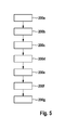
Entsprechend der Darstellung der
- (200a) der Kraftstoffdruck in
dem Druckspeicher 13 wird während des ersten und des zweiten Messintervalls 60 bzw. 62 (siehe dazu dieFigur 3 ) mittels der Druckregelung 19 auf einen jeweils gleichen Drucksollwert 66 (siehe dazu dieFigur 3 ) geregelt; - (200b) der Aktor 18 des Einspritzventils 9 wird während des ersten Messintervalls 60 periodisch mehrfach kurz angesteuert, so dass eine Steuermenge des Kraftstoffs aus
dem Druckspeicher 13 entnommen wird, wobei das Einspritzventil 9 nicht bereits Kraftstoff inden Brennraum 4 einspritzt; - (200c) während der Ansteuerung des Einspritzventils 9 wird ein erster Wert einer Betriebsgröße der Druckregelung 19, insbesondere einer Stellgröße 25 eines Druckreglers und/oder der Zumesseinrichtung 22 und/oder des Druckregelventils 14a ermittelt;
- (200d) das Einspritzventil 9 wird während des zweiten Messintervalls 62 so angesteuert, dass keine Steuermenge des Kraftstoffs aus
dem Druckspeicher 13 entnommen wird; dabei wird der Aktor 18 in diesem Schritt (d) bevorzugt gar nicht angesteuert; - (200e) es wird ein zweiter Wert der Betriebsgröße der Druckregelung 19 ermittelt;
- (200f) es wird eine Differenz 70 (siehe dazu die
Figur 3 ) zwischen dem ersten Wert und dem zweiten Wert der Betriebsgröße ermittelt; und - (200g) die
Differenz 70 wird mit einer in der Steuer- und/oder Regeleinrichtung 15 der Brennkraftmaschine 1gespeicherten Differenz 70, welche unter vergleichbaren Bedingungen ermittelt wurde, verglichen, und daraus auf einen Zustand des Drucksensors 14 geschlossen.
- (200a) the fuel pressure in the
pressure accumulator 13 is during the first and thesecond measurement interval 60 and 62 (see theFIG. 3 ) by means of thepressure control 19 to a respective same pressure setpoint 66 (see theFIG. 3 ) regulated; - (200b) the actuator 18 of the injection valve 9 is periodically activated several times during the
first measurement interval 60, so that a control amount of the fuel is taken from thepressure accumulator 13, wherein the injection valve 9 is not already injecting fuel into thecombustion chamber 4; - (200c) during the control of the injection valve 9 is a first value of an operating variable of the
pressure control 19, in particular a manipulated variable 25th a pressure regulator and / or themetering device 22 and / or thepressure regulating valve 14a determined; - (200d) the injection valve 9 is controlled during the
second measurement interval 62 so that no control amount of the fuel is removed from thepressure accumulator 13; In this case, the actuator 18 is preferably not activated in this step (d); - (200e) a second value of the operating quantity of the
pressure control 19 is determined; - (200f) there will be a difference 70 (see the
FIG. 3 ) between the first value and the second value of the operating quantity; and - (200g) the
difference 70 is compared with a stored in the control and / or regulatingdevice 15 of the internal combustion engine 1difference 70, which was determined under comparable conditions, and concluded therefrom to a state of thepressure sensor 14.
Bei der Durchführung der genannten Schritte (200a) bis (200g) werden der Kraftstoffdruck, die Kraftstofftemperatur, und die Kraftstoffsorte als Parameter berücksichtigt.In performing the above steps (200a) to (200g), the fuel pressure, the fuel temperature, and the fuel grade are taken into consideration as parameters.
Beide Balkendiagramme 30 und 32 veranschaulichen zusammen die der Erfindung zugrunde liegende Bilanz. Man erkennt, dass die Leckage 40 beispielsweise eines "alten" Einspritzventils 9 stärker ist, als die Leckage 38 eines "neuen" Einspritzventils 9. Die Steuermengen 42 und 44 sind dagegen gleich. Daher werden die Steuermengen 42 bzw. 44 dazu verwendet, um in einem ersten Messintervall 60 (siehe die nachfolgenden
Falls die verfahrensgemäß nach einer bestimmten Betriebsdauer ermittelte Steuermenge 44 von der im Neuzustand ermittelten Steuermenge 42 abweicht, so wird - wegen der vorausgesetzten guten Reproduzierbarkeit der Steuermengen 42 und 44 - erfindungsgemäß angenommen, dass die Ursache dafür ein nicht korrekt geregelter Kraftstoffdruck in dem Druckspeicher 13 ist.If, according to the method, the
Für den Fall, dass - bei einem scheinbar korrekt geregelten Kraftstoffdruck in dem Druckspeicher 13 - die Steuermenge 44 größer als die Steuermenge 42 ist, wird angenommen, dass der Drucksensor 14 einen zu niedrigen Kraftstoffdruck im Druckspeicher 13 anzeigt, das heißt, der tatsächliche Kraftstoffdruck ist größer. Für den Fall, dass - bei einem scheinbar korrekt geregelten Kraftstoffdruck in dem Druckspeicher 13 - die Steuermenge 44 kleiner als die Steuermenge 42 ist, wird angenommen, dass der Drucksensor 14 einen zu hohen Kraftstoffdruck im Druckspeicher 13 anzeigt, das heißt, der tatsächliche Kraftstoffdruck ist kleiner.In the event that - at a seemingly correctly controlled fuel pressure in the pressure accumulator 13 - the
In einem in der Zeichnung mittleren Bereich ist jeweils eine Betriebsgröße 64 der Druckregelung 19 des Kraftstoffeinspritzsystems 100 eingetragen. Die Betriebsgröße 64 charakterisiert eine Rate des aus dem Druckspeicher 13 entnommenen Kraftstoffs. In einem in der Zeichnung oberen Bereich ist ein jeweils zugehöriger Drucksollwert 66 eingetragen, welcher einen Parameter darstellt. Ein Kraftstoffdruck 68 wird in Abhängigkeit von dem Drucksollwert 66 geregelt.In a middle region in the drawing, an operating
Die in den Diagrammen (A) bis (D) in dem mittleren und dem oberen Bereich dargestellten Kurven weisen aus Gründen der zeichnerischen Darstellung teilweise einen vertikalen Versatz zueinander auf. Beispielsweise wird in der
In dem ersten Messintervall 60 erfolgen jeweils periodisch mehrere Entnahmen von Kraftstoff aus dem Druckspeicher 13. Dabei wird der Aktor 18 des Einspritzventils 9 bei jeder einzelnen Entnahme derart kurz angesteuert, dass das Einspritzventil 9 nicht bereits Kraftstoff in den Brennraum 4 der Brennkraftmaschine 1 einspritzt. Dadurch wird jeweils eine Steuermenge des Kraftstoffs zum Ansteuern eines Servoventils des Einspritzventils 9 aus dem Druckspeicher 13 entnommen und anschließend über einen Rücklauf wieder dem Kraftstoffeinspritzsystem 100 zugeführt. Dabei wird jedoch kein Beitrag zu einem Drehmoment der Brennkraftmaschine 1 geleistet.In the first measuring
In dem zweiten Messintervall 62 erfolgt keine derartige Entnahme von Kraftstoff, das heißt, das Servoventil wird nicht zur Entnahme einer Steuermenge des Kraftstoffs betätigt. Die übrigen Betriebsbedingungen der Brennkraftmaschine 1 in dem zweiten Messintervall 62 sollen jedoch den Betriebsbedingungen während des ersten Messintervalls 60 möglichst gleichen. Vorzugsweise folgen das erste und das zweite Messintervall 60 und 62 daher unmittelbar aufeinander.In the
Aus einer Differenz 70 der in dem jeweils ersten und zweiten Messintervall 60 und 62 ermittelten Betriebsgrößen 64 kann die während des ersten Messintervalls 60 zusätzlich entnommene Kraftstoffmenge bei der mindestens einen Entnahme ermittelt werden. Vorzugsweise wird die Differenz 70 aus Mittelwerten der Betriebsgrößen 64 während des ersten Messintervalls 60 und des zweiten Messintervalls 62 gebildet, um die Genauigkeit des Verfahrens zu erhöhen. Eine bestimmte Reihenfolge des ersten Messintervalls 60 und des zweiten Messintervalls 62 ist jedoch nicht erforderlich, das heißt, in den Diagrammen (A) bis (D) kann das "zweite" Messintervall 62 gegebenenfalls auch zeitlich vor dem zugehörigen ersten Messintervall 60 angeordnet sein.From a
Das erfindungsgemäße Verfahren ist besonders einfach und genau durchführbar, wenn es in einer Betriebsart der Brennkraftmaschine 1 durchgeführt wird, in der üblicherweise keine Einspritzung von Kraftstoff in den Brennraum 4 der Brennkraftmaschine 1 vorgesehen ist. Beispielsweise kann dies in einem Schubbetrieb der Brennkraftmaschine 1 erfolgen, in welchem für eine vergleichsweise lange Zeitspanne kein Kraftstoff eingespritzt wird. Es ist jedoch ebenso möglich, das Verfahren in einer Gaswechselphase während eines oder mehrerer Arbeitszyklen der Brennkraftmaschine 1 durchzuführen.The inventive method is particularly simple and accurate to carry out when it is performed in an operating mode of the internal combustion engine 1, in which usually no injection of fuel is provided in the
Man erkennt aus den
Claims (10)
Applications Claiming Priority (1)
| Application Number | Priority Date | Filing Date | Title |
|---|---|---|---|
| DE102011075124A DE102011075124A1 (en) | 2011-05-03 | 2011-05-03 | Method for operating a fuel injection system of an internal combustion engine |
Publications (1)
| Publication Number | Publication Date |
|---|---|
| EP2520788A2 true EP2520788A2 (en) | 2012-11-07 |
Family
ID=46052566
Family Applications (1)
| Application Number | Title | Priority Date | Filing Date |
|---|---|---|---|
| EP12165871A Withdrawn EP2520788A2 (en) | 2011-05-03 | 2012-04-27 | Method for operating a fuel injection system for a combustion engine |
Country Status (3)
| Country | Link |
|---|---|
| US (1) | US9494102B2 (en) |
| EP (1) | EP2520788A2 (en) |
| DE (1) | DE102011075124A1 (en) |
Families Citing this family (3)
| Publication number | Priority date | Publication date | Assignee | Title |
|---|---|---|---|---|
| EP2926953A1 (en) * | 2014-04-04 | 2015-10-07 | HILTI Aktiengesellschaft | Method and system for controlling injection processes |
| DE102015211024B4 (en) * | 2015-06-16 | 2017-07-20 | Continental Automotive Gmbh | A monitoring method for monitoring a leakage balance in an injector assembly, driving method for driving an injector and electronic control unit |
| JP2018162761A (en) * | 2017-03-27 | 2018-10-18 | 三菱自動車工業株式会社 | Engine control apparatus |
Family Cites Families (6)
| Publication number | Priority date | Publication date | Assignee | Title |
|---|---|---|---|---|
| US6076504A (en) * | 1998-03-02 | 2000-06-20 | Cummins Engine Company, Inc. | Apparatus for diagnosing failures and fault conditions in a fuel system of an internal combustion engine |
| JP3884577B2 (en) * | 1998-08-31 | 2007-02-21 | 株式会社日立製作所 | Control device for internal combustion engine |
| EP1008741B1 (en) * | 1998-11-20 | 2003-04-02 | Mitsubishi Jidosha Kogyo Kabushiki Kaisha | Accumulator type fuel injection system |
| JP4321342B2 (en) * | 2004-04-22 | 2009-08-26 | 株式会社デンソー | Common rail fuel injection system |
| US8091531B2 (en) * | 2009-04-22 | 2012-01-10 | GM Global Technology Operations LLC | Diagnostic systems and methods for a pressure sensor during idle conditions |
| US8220322B2 (en) * | 2009-04-30 | 2012-07-17 | GM Global Technology Operations LLC | Fuel pressure sensor performance diagnostic systems and methods based on hydrostatics in a fuel system |
-
2011
- 2011-05-03 DE DE102011075124A patent/DE102011075124A1/en not_active Withdrawn
-
2012
- 2012-04-19 US US13/451,094 patent/US9494102B2/en not_active Expired - Fee Related
- 2012-04-27 EP EP12165871A patent/EP2520788A2/en not_active Withdrawn
Non-Patent Citations (1)
| Title |
|---|
| None |
Also Published As
| Publication number | Publication date |
|---|---|
| DE102011075124A1 (en) | 2012-11-08 |
| US9494102B2 (en) | 2016-11-15 |
| US20120283933A1 (en) | 2012-11-08 |
Similar Documents
| Publication | Publication Date | Title |
|---|---|---|
| DE102007028900B4 (en) | Method and device for diagnosing an injection valve of an internal combustion engine that is in communication with a fuel rail | |
| DE102006034514B4 (en) | Method for controlling an internal combustion engine | |
| EP2148070A2 (en) | Method for determining the injected fuel mass of a single injection and device for carrying out the method | |
| EP2758650B1 (en) | Method for assessing an injection behaviour of at least one injection valve in an internal combustion engine and operating method for an internal combustion engine | |
| WO2007134887A1 (en) | Method and device for controlling an injection valve of an internal combustion engine | |
| DE102007000067B4 (en) | Fuel injection device | |
| DE102012218176A1 (en) | Method for operating a fuel injection system | |
| DE102005036192A1 (en) | Fuel injection system e.g. high pressure-based fuel injection system, controlling method for e.g. self-ignition internal combustion engine, involves implementing compression wave correction based on periodic model that models masses wave | |
| EP1797308A1 (en) | Method for the operation of an internal combustion engine | |
| WO2006074842A1 (en) | Method and device for controlling an injector | |
| DE102005020686A1 (en) | Method for controlling a fuel supply device of an internal combustion engine | |
| DE102007050813A1 (en) | Method for monitoring delivery quantity with valve control for internal combustion engine, particularly valve control for spark-ignition internal combustion engine, involves controlling valve of internal combustion engine | |
| DE60318195T2 (en) | DIESEL ENGINE WITH A DEVICE FOR CONTROLLING THE STREAM OF INJECTION-MOLDED FUEL | |
| DE102010029933B4 (en) | Method and device for operating a fuel injection system | |
| EP2520788A2 (en) | Method for operating a fuel injection system for a combustion engine | |
| DE10303573B4 (en) | Method, computer program, storage medium and control and / or regulating device for operating an internal combustion engine, and internal combustion engine, in particular for a motor vehicle | |
| DE102011056159A1 (en) | Fuel injection controller for use in common-rail fuel injection system utilized in i.e. four-cylinder diesel engine, of automobile, has injection characteristic calculating section calculating injection characteristic of fuel injector | |
| DE10305525B4 (en) | Method and device for adapting the pressure wave correction in a high-pressure injection system of a motor vehicle while driving | |
| EP2896809B1 (en) | Method for determining an injection pressure and motor vehicle | |
| EP2019195A1 (en) | Method for determining the amount of fuel injected | |
| DE102017126111A1 (en) | SYSTEMS AND METHOD FOR CONTROLLING FLUID INJECTION | |
| DE10248627A1 (en) | Method for operating an internal combustion engine, burner crater and control device therefor | |
| DE102007009565A1 (en) | Method for determining fuel composition in injection system of internal-combustion engine particularly of motor vehicle, involves determining physical parameter assigned to fuel pressure wave | |
| DE102007053404A1 (en) | Method for correcting control function for injector of injection engine, involves determining internal pressure in cylinder of injection engine which is assigned to injector | |
| WO2013156377A1 (en) | Method and device for operating an internal combustion engine |
Legal Events
| Date | Code | Title | Description |
|---|---|---|---|
| PUAI | Public reference made under article 153(3) epc to a published international application that has entered the european phase |
Free format text: ORIGINAL CODE: 0009012 |
|
| AK | Designated contracting states |
Kind code of ref document: A2 Designated state(s): AL AT BE BG CH CY CZ DE DK EE ES FI FR GB GR HR HU IE IS IT LI LT LU LV MC MK MT NL NO PL PT RO RS SE SI SK SM TR |
|
| AX | Request for extension of the european patent |
Extension state: BA ME |
|
| STAA | Information on the status of an ep patent application or granted ep patent |
Free format text: STATUS: THE APPLICATION IS DEEMED TO BE WITHDRAWN |
|
| 18D | Application deemed to be withdrawn |
Effective date: 20171103 |