EP2520773A2 - Combustion engine with at least one combustion chamber - Google Patents
Combustion engine with at least one combustion chamber Download PDFInfo
- Publication number
- EP2520773A2 EP2520773A2 EP11009800A EP11009800A EP2520773A2 EP 2520773 A2 EP2520773 A2 EP 2520773A2 EP 11009800 A EP11009800 A EP 11009800A EP 11009800 A EP11009800 A EP 11009800A EP 2520773 A2 EP2520773 A2 EP 2520773A2
- Authority
- EP
- European Patent Office
- Prior art keywords
- piston
- cylinder unit
- rocker arm
- valve
- internal combustion
- Prior art date
- Legal status (The legal status is an assumption and is not a legal conclusion. Google has not performed a legal analysis and makes no representation as to the accuracy of the status listed.)
- Granted
Links
- 238000002485 combustion reaction Methods 0.000 title claims abstract description 39
- 230000007246 mechanism Effects 0.000 claims abstract description 24
- 238000000034 method Methods 0.000 claims abstract description 6
- 230000033001 locomotion Effects 0.000 claims description 53
- 230000000903 blocking effect Effects 0.000 claims description 16
- 230000006837 decompression Effects 0.000 claims description 4
- 230000000694 effects Effects 0.000 description 11
- 210000002414 leg Anatomy 0.000 description 11
- 230000001133 acceleration Effects 0.000 description 7
- 230000003111 delayed effect Effects 0.000 description 5
- 230000006835 compression Effects 0.000 description 4
- 238000007906 compression Methods 0.000 description 4
- 230000008878 coupling Effects 0.000 description 4
- 238000010168 coupling process Methods 0.000 description 4
- 238000005859 coupling reaction Methods 0.000 description 4
- 238000003860 storage Methods 0.000 description 4
- 230000008901 benefit Effects 0.000 description 3
- 230000004044 response Effects 0.000 description 3
- 230000009471 action Effects 0.000 description 2
- 230000004913 activation Effects 0.000 description 2
- 238000006243 chemical reaction Methods 0.000 description 2
- 239000000428 dust Substances 0.000 description 2
- 238000005461 lubrication Methods 0.000 description 2
- 230000009467 reduction Effects 0.000 description 2
- 101100074336 Xenopus laevis ripply2.1 gene Proteins 0.000 description 1
- 238000013459 approach Methods 0.000 description 1
- 230000009286 beneficial effect Effects 0.000 description 1
- 238000010276 construction Methods 0.000 description 1
- 230000007547 defect Effects 0.000 description 1
- 230000001419 dependent effect Effects 0.000 description 1
- 238000011161 development Methods 0.000 description 1
- 230000018109 developmental process Effects 0.000 description 1
- 238000005553 drilling Methods 0.000 description 1
- 210000003414 extremity Anatomy 0.000 description 1
- 230000002349 favourable effect Effects 0.000 description 1
- 238000007667 floating Methods 0.000 description 1
- 230000001050 lubricating effect Effects 0.000 description 1
- 238000004519 manufacturing process Methods 0.000 description 1
- 238000011084 recovery Methods 0.000 description 1
- 230000000979 retarding effect Effects 0.000 description 1
- 230000003068 static effect Effects 0.000 description 1
- 230000001360 synchronised effect Effects 0.000 description 1
- 210000000689 upper leg Anatomy 0.000 description 1
Images


Classifications
-
- F—MECHANICAL ENGINEERING; LIGHTING; HEATING; WEAPONS; BLASTING
- F01—MACHINES OR ENGINES IN GENERAL; ENGINE PLANTS IN GENERAL; STEAM ENGINES
- F01L—CYCLICALLY OPERATING VALVES FOR MACHINES OR ENGINES
- F01L13/00—Modifications of valve-gear to facilitate reversing, braking, starting, changing compression ratio, or other specific operations
- F01L13/06—Modifications of valve-gear to facilitate reversing, braking, starting, changing compression ratio, or other specific operations for braking
-
- F—MECHANICAL ENGINEERING; LIGHTING; HEATING; WEAPONS; BLASTING
- F01—MACHINES OR ENGINES IN GENERAL; ENGINE PLANTS IN GENERAL; STEAM ENGINES
- F01L—CYCLICALLY OPERATING VALVES FOR MACHINES OR ENGINES
- F01L1/00—Valve-gear or valve arrangements, e.g. lift-valve gear
- F01L1/12—Transmitting gear between valve drive and valve
- F01L1/18—Rocking arms or levers
- F01L1/181—Centre pivot rocking arms
-
- F—MECHANICAL ENGINEERING; LIGHTING; HEATING; WEAPONS; BLASTING
- F01—MACHINES OR ENGINES IN GENERAL; ENGINE PLANTS IN GENERAL; STEAM ENGINES
- F01L—CYCLICALLY OPERATING VALVES FOR MACHINES OR ENGINES
- F01L1/00—Valve-gear or valve arrangements, e.g. lift-valve gear
- F01L1/26—Valve-gear or valve arrangements, e.g. lift-valve gear characterised by the provision of two or more valves operated simultaneously by same transmitting-gear; peculiar to machines or engines with more than two lift-valves per cylinder
- F01L1/267—Valve-gear or valve arrangements, e.g. lift-valve gear characterised by the provision of two or more valves operated simultaneously by same transmitting-gear; peculiar to machines or engines with more than two lift-valves per cylinder with means for varying the timing or the lift of the valves
-
- F—MECHANICAL ENGINEERING; LIGHTING; HEATING; WEAPONS; BLASTING
- F01—MACHINES OR ENGINES IN GENERAL; ENGINE PLANTS IN GENERAL; STEAM ENGINES
- F01L—CYCLICALLY OPERATING VALVES FOR MACHINES OR ENGINES
- F01L13/00—Modifications of valve-gear to facilitate reversing, braking, starting, changing compression ratio, or other specific operations
- F01L13/06—Modifications of valve-gear to facilitate reversing, braking, starting, changing compression ratio, or other specific operations for braking
- F01L13/065—Compression release engine retarders of the "Jacobs Manufacturing" type
-
- F—MECHANICAL ENGINEERING; LIGHTING; HEATING; WEAPONS; BLASTING
- F01—MACHINES OR ENGINES IN GENERAL; ENGINE PLANTS IN GENERAL; STEAM ENGINES
- F01L—CYCLICALLY OPERATING VALVES FOR MACHINES OR ENGINES
- F01L1/00—Valve-gear or valve arrangements, e.g. lift-valve gear
- F01L1/02—Valve drive
- F01L1/04—Valve drive by means of cams, camshafts, cam discs, eccentrics or the like
- F01L1/047—Camshafts
- F01L1/053—Camshafts overhead type
-
- F—MECHANICAL ENGINEERING; LIGHTING; HEATING; WEAPONS; BLASTING
- F01—MACHINES OR ENGINES IN GENERAL; ENGINE PLANTS IN GENERAL; STEAM ENGINES
- F01L—CYCLICALLY OPERATING VALVES FOR MACHINES OR ENGINES
- F01L1/00—Valve-gear or valve arrangements, e.g. lift-valve gear
- F01L1/20—Adjusting or compensating clearance
-
- F—MECHANICAL ENGINEERING; LIGHTING; HEATING; WEAPONS; BLASTING
- F01—MACHINES OR ENGINES IN GENERAL; ENGINE PLANTS IN GENERAL; STEAM ENGINES
- F01L—CYCLICALLY OPERATING VALVES FOR MACHINES OR ENGINES
- F01L13/00—Modifications of valve-gear to facilitate reversing, braking, starting, changing compression ratio, or other specific operations
- F01L2013/10—Auxiliary actuators for variable valve timing
- F01L2013/105—Hydraulic motors
-
- F—MECHANICAL ENGINEERING; LIGHTING; HEATING; WEAPONS; BLASTING
- F01—MACHINES OR ENGINES IN GENERAL; ENGINE PLANTS IN GENERAL; STEAM ENGINES
- F01L—CYCLICALLY OPERATING VALVES FOR MACHINES OR ENGINES
- F01L2305/00—Valve arrangements comprising rollers
-
- F—MECHANICAL ENGINEERING; LIGHTING; HEATING; WEAPONS; BLASTING
- F01—MACHINES OR ENGINES IN GENERAL; ENGINE PLANTS IN GENERAL; STEAM ENGINES
- F01L—CYCLICALLY OPERATING VALVES FOR MACHINES OR ENGINES
- F01L2810/00—Arrangements solving specific problems in relation with valve gears
- F01L2810/02—Lubrication
Definitions
- the invention relates to an internal combustion engine having at least one combustion chamber, from which by means of at least one exhaust valve exhaust is discharged, comprising an engine brake device with a hydraulic auxiliary valve control unit, which is integrated into the exhaust valve with a camshaft connecting link mechanism and the exhaust valve when the engine brake device in an intermediate-open position and a hydraulic valve clearance compensation mechanism for the exhaust valve, wherein the link mechanism comprises at least one rocker arm and an intermediate member disposed between the rocker arm and the exhaust valve and the hydraulic auxiliary valve control unit of the engine braking device comprises a first piston-cylinder unit for temporary intermediate opening of an exhaust valve and the hydraulic lash adjuster mechanism comprises a second piston-cylinder unit for counteracting valve lash.
- US 2010/319657 A1 is known a method and a system with an EVB (Exhaust Valve Brake), in which the braking energy of the engine is achieved by the combination of a motor dust brake and a decompression brake.
- EVB Exhaust Valve Brake
- the US 2010/0319657 A1 in that two exhaust valves are controlled on a valve bridge, wherein one of the exhaust valves is mounted on the valve bridge by a piston-cylinder unit movable and controllable.
- This first piston-cylinder unit in the valve bridge ensures the feasibility and holding an open position of the linearly displaceable exhaust valve of the valve bridge and thus the possibility of braking.
- valve bridge comprises a second piston-cylinder unit, which serves as a connecting means to the valve-side leg of the rocker arm, wherein on the upper side of this rocker arm leg of the rocker arm is biased by a spring.
- camshaft is provided with a larger main exhaust cam and a smaller compression reduction cam. With each revolution of the camshaft, regardless of whether a braking operation has been initiated, the rocker arm responds to the two cams of the camshaft.
- an oil guide channel extending from the center of the rocker arm via the connecting elements, to the second piston-cylinder unit and from this to the first piston-cylinder unit, the system is applied during the braking phase with an oil pressure, which is controlled with the the channel connected elements acts.
- an outlet opening of the valve bridge which is closed in phases by an anvil, the oil trapped in the valve bridge or the oil pressure can escape or be decomposed at certain times (when passing through the large cam).
- a disadvantage of this system is that on the one hand an active activation namely an oil pressure loading is required to open the exhaust valve for the braking effect of the engine and keep it open.
- an active activation namely an oil pressure loading is required to open the exhaust valve for the braking effect of the engine and keep it open.
- the construction of an oil pressure within the rocker arm, the valve bridge and the parts connecting them is problematic because in the course of using this system, the tolerances and in particular the tightness of the aforementioned elements can vary greatly, which directly affects the reliability of the pressure build-up and thus can affect the controllability of the outlet opening.
- the entire system always passes through both cams. The movement of the compression reduction cam in the non-braking state represents an unnecessary expenditure of energy and increases the wear of the entire system.
- the invention has the object of providing an internal combustion engine with the features of the preamble of claim 1 and a method of operating an internal combustion engine according to the preamble of claim 15 such that in a simple and reliable way a valve clearance compensation and at the same time a combined engine dust and decompression brake ( EVB) is executable. It is another object of the invention to make the system such that it is easy to manufacture, is subject to low wear, the executed movements of the elements are low and have a low frictional resistance. A further object of the invention is to enable a passively controlled EVB which manages without an actively acting electronic / electrical or hydraulic control line.
- the first piston-cylinder unit is arranged in or on the intermediate element and the second piston-cylinder unit in or on the rocker arm.
- Another core of the invention is to take advantage of this delay of the response of the two piston-cylinder units to each other and to take into account in the interpretation that substantially minimizes undesirable effects of a piston-cylinder unit to the other piston-cylinder unit and / or completely excluded.
- the intermediate element usually including, inter alia, a valve bridge is not firmly connected to the rocker arm and a gap could result if the valves would perform a fast to the combustion chamber directed movement. Such a gap would lead to an albeit small proportion of movement of the rocker arm is possible without direct influence on the intermediate element.
- this rate of motion inertia forces may act as a drag and / or acceleration retarding effect on the rocker arm.
- this forces When a force acts on the rocker arm, this forces a rotational movement, this movement is carried out only with delay or with a delayed acceleration, since the mass of the rocker arm acts.
- this effect can be used positively in the case of a valve jump, since the restoring force of the hydraulic valve play compensation (from the second piston-cylinder unit) can therefore only have a limited effect on a possible undesired adjustment movement of the rocker arm in the direction of valves.
- This can lead to the introduction of force acting on the rocker arm and its movement / acceleration so late that the second piston-cylinder unit arranged on the rocker arm does not react directly and thus delayed and thus unwanted movement and / or acceleration of the second piston Cylinder unit prevented or thereby at least can be minimized so that only a negligible impact on the overall system.
- the first and the second piston-cylinder unit for oil supply are connected to a common oil source, wherein the first and the second piston-cylinder unit are each connected to the oil source without the interposition of the other.
- the valve drive or the connection mechanism is fed, for example, by an oil feed present at the bearing of the rocker arm.
- the provided there with a substantially constant pressure oil is passed through oil passages both to the first and the second piston-cylinder unit and to bearings of movably mounted parts.
- the decoupling of leading to the first and second piston-cylinder unit oil channels also supports the delayed, decoupled and thus more independent function of each piston-cylinder unit.
- the rocker arm has at least two legs enclosing an angle.
- the second piston-cylinder unit in or on the camshaft facing leg of the Rocker be arranged.
- the second piston-cylinder unit arranged in or on one limb of the rocker arm is arranged between a rocker arm bearing and the intermediate element or the valve bridge, preferably with the interposition of a further separately movable rocker arm element.
- the former variant is characterized by the fact that the arrangement of the second piston-cylinder unit on the opposite side of the valve bridge leg of the rocker arm, the effect of inertia on the movement of the rocker arm is amplified.
- a series connection of the oil supply of the first and second piston-cylinder unit can be realized.
- an arrangement of the second piston-cylinder unit between the rocker arm bearing and the intermediate elements or on the intermediate element (eg., The valve bridge) associated side starting from the rocker arm be beneficial.
- the intermediate element may comprise, as an essential component, a valve bridge which connects at least two exhaust valves to one another. Furthermore, the intermediate element may also comprise connecting links between the rocker arm and the outlet valve. In the following, reference is made to embodiments in which the intermediate element is designed as a valve bridge.
- the active systems for shifting the exhaust valve to an intermediate open position either use direct electronic / electrical control of an exhaust valve or initiate it via a control circuit operating at a defined controllable oil pressure.
- the passive systems to this effect are characterized by the fact that the intermediate opened position of the exhaust valve initiated by an exhaust gas backflow stagnated in the exhaust duct, or that the exhaust valve is stopped in its closing movement in an intermediate position. In this case, a flap in the exhaust duct is closed to achieve the braking effect of the engine, which builds up from there exhaust gas builds up a back pressure, which is the closing of the linearly movably mounted in the valve bridge Counteracts exhaust valve.
- the blocking effect of the first piston-cylinder unit keeps the outlet valve open.
- the rocker arm is constructed in several parts and comprises a base body and a carrier body, wherein the carrier body is movably mounted relative to the base body and the relative mobility of the base body and carrier body through the second piston-cylinder unit can be influenced.
- a biasing force can act between the two levers, so that a hydraulic valve clearance compensation (HVA) can be carried out by the relative movement of the base body and carrier body.
- HVA hydraulic valve clearance compensation
- a correspondingly biased spring can apply the restoring force.
- the second piston-cylinder unit is designed in the manner of a one-way valve and executed with a biasing action relative to the carrier body to the camshaft with the second piston-cylinder unit ensures a substantially rigid connection between the rocker arm and the camshaft in a locked phase.
- a deflection is carried out during a readjustment phase.
- the second piston-cylinder unit forms an integral part of the hydraulic valve clearance compensation and ensures that in the event that between the contact region of the support body (eg a roller) and the camshaft resulting due to wear or other circumstances gap Adjustment of the second piston-cylinder unit reliably remains closed, or does not form.
- the method according to the invention is applied to an overhead camshaft engine.
- a contacting with the camshaft contact element is arranged on the carrier body or movably mounted on the carrier body, wherein preferably the contact element is designed as a rotatably mounted on the carrier body roller.
- the carrier body thus acts as a carrier of the contact element designed as a roller and allows movement of the contact element in response to the movement of the camshaft.
- the carrier body is in turn movably mounted on the main body or parallel to this at, for example, a rocker shaft. If the carrier body is movably mounted on the base body, this can be realized either by a rotary bearing which ensures a rotational movement of the carrier body relative to the base body or by a linear bearing which ensures a linear movement of the carrier body relative to the base body become.
- the longitudinal axis of the second piston-cylinder unit with an auxiliary line extending from a point of retracted end position of the second piston-cylinder unit to the center of the axis of rotation of the camshaft and / or spans to the center of the axis of rotation of a rotatably mounted contact element encloses an angle of 45 ° to - 45 °.
- the longitudinal axis of the second piston-cylinder unit to the longitudinal axis of the linear movement of the support body forms an angle of 45 ° to - 45 ° or aligned parallel thereto.
- the angular range between 20 ° to -20 °, particularly preferably between 10 ° to -10 °, both for the rotatable and for the linearly displaceable support body.
- the first and the second piston-cylinder unit are preferably each provided with a biased by a spring piston, a pressure chamber and a pressure chamber at least in phases occlusive locking element.
- the blocking element and the pressure chamber make it possible for these elements to be used as blocking means by the oil temporarily trapped in the pressure chamber. Due to the blocking function of the second piston-cylinder unit, the mobility of the carrier to the main body can be largely inhibited. By the blocking function of the first piston-cylinder unit, a holding function of the exhaust valve in an intermediate open position executable.
- the pressure chamber of the first piston-cylinder unit comprises a leading to the outside of the pressure chamber of the intermediate element oil passage which is phase-locked by a counter-holder substantially oil-tight.
- the closing function of the counter-holder with regard to the oil passage of the pressure chamber of the first piston-cylinder unit leading from the intermediate element is active when the rocker arm runs on the base circle of the cam and thus the valve bridge remains in its closed valve position ,
- the rocker arm, starting from the passage of the cam a Performs tilting movement, thereby the valve bridge is pressed down, the counter-holder as relative to the pivot point to the rocker arm fixed element remains in place, so that the leading from the pressure chamber of the first piston-cylinder unit oil passage is released to the outside of the valve bridge, so that the In the pressure chamber prevailing oil pressure is removed and the blocking function of the first piston-cylinder unit is canceled, and thus the exhaust valve actuated in the first piston-cylinder unit or connected is moved back into its closing end position by the spring force of the valve springs.
- the system according to the invention can be applied to both active and passive EVBs.
- a particularly advantageous embodiment is achieved in that the inventive idea underlying the main claim is applied to a passive EVB and the engine braking effect is achieved by keeping open an exhaust valve and / or not by an additional operating exclusively for the braking effect valve.
- the device according to the invention is also based on a method which is characterized essentially by the fact that the internal combustion engine is provided with at least one two-part rocker arm for operating an internal combustion engine with a hydraulic valve lash adjuster and a combined engine stall and decompression brake, which comprises a carrier body and a base body perform in the case of the valve clearance compensation relative movement to each other, wherein in a short-term movement of the valve and / or the intermediate element, the second piston-cylinder unit due to their arrangement in or on the rocker arm and / or the inertia of the rocker arm an insignificant or no movement of the carrier body is performed relative to the main body.
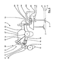
- FIG. 1 shows the essential elements of the invention.
- An internal combustion engine is provided with at least one combustion chamber 1, from which exhaust gas can be discharged by means of at least one exhaust valve 2, 2 ', wherein the internal combustion engine is provided with an engine brake device with a hydraulic additional valve control unit 3.
- the auxiliary valve control unit 3 is integrated into a connecting mechanism 5 connecting the exhaust valve 2, 2 'to a camshaft 4, the exhaust valve 2 being held in an intermediate open position Z when the engine braking device is actuated.
- the valves 2, 2 ' are moved by the reaction of the rocker arm 6 to the position of the camshaft 4 between a closed position S and an open position O back and forth. Only one of the exhaust valves 2, 2 'namely exhaust valve 2 can be kept temporarily or during a braking phase by the additional valve control unit 3 in the case of a braking operation in an intermediate open position Z.
- the internal combustion engine comprises a hydraulic valve clearance compensation mechanism 7 by which occurring in the course of wear of individual elements of the connecting mechanism 5 wear and thus a game within the system by adjusting individual elements is avoided.
- the connecting mechanism 5 further comprises a rocker arm 6 and an intermediate element 8 arranged between the rocker arm 6 and the outlet valve 2, 2 '.
- the intermediate element 8 is designed in the illustrated embodiment as a valve bridge 9 which couples two exhaust valves 2, 2' to one another tilting lever side adjustably mounted adjusting screw 10 is in contact.
- the adjusting screw 10 is connected via a coupling element 29 with the valve bridge 9, the coupling element 29 may be an integral part of the intermediate element 8 or an attached component of the intermediate element 8.
- the coupling element 29 is in the illustrated embodiment on the valve bridge 9 and can move away from this.
- the hydraulic additional valve control unit 3 provides a first piston-cylinder unit 11.
- the hydraulic valve clearance compensation mechanism 7 comprises a second piston-cylinder unit 12 which counteracts the occurrence of a valve clearance.
- the first piston-cylinder unit 11 is arranged in the illustrated embodiment in the valve bridge 9 and the second piston-cylinder unit 12 in the rocker arm 6.
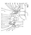
- connection mechanism 5 In the FIGS. 1 . 2 . 3 . 5 . 7 . 8th and 9 the connection mechanism 5 is always aligned on the base circle of the camshaft 4 and thus in its normal position G. In the FIGS. 4 and 6 the connection mechanism 5 is moved out of the basic position G by the cam 13 of the camshaft 4 into a position which brings the valves 2, 2 'into the open position O.
- the first and the second piston-cylinder unit 11, 12 is connected to the oil supply to a common oil source here in the storage area 14 of the rocker arm 6, wherein the first and second piston-cylinder unit 11, 12 respectively without interposition of the other piston Cylinder unit 11, 12 is connected to the oil source.
- oil is passed through an axial bore 15 to the center of the bearing 14 and from there via channel sections 16, 16 ', 16 "within the bearing 14 to the camshaft side of the rocker arm 6, to the valve bridge side of the rocker arm. 6 and to lubrication regions 17 for lubricating the rotational movement of the rocker arm 6 relative to the bearing 14.
- the channel section 16 merges into the oil passages 18, 18 'which guide the oil to bearings or the axes of rotation 19, 20 of a carrier body 21 and a roller 22, respectively
- the channel portion 18 ' also disposed in the rocker arm 6 directs the oil to the second piston-cylinder unit 12.
- the channel portion 16 guides the oil through a passage portion 23 to the adjusting screw 10 within which an axial oil guide bore (not shown) is located in turn, the oil leads to the valve bridge 9 and there in an arranged within the valve bridge 9 oil passage 24 to a pressure chamber 25 of the ers th piston-cylinder unit 11 leads.
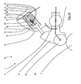
- the rocker arm 6 is preferably provided with two legs 26, 26 'enclosing an angle ⁇ , the second piston-cylinder unit 12 being arranged in the leg 26 of the rocker arm 6 facing the camshaft 4, cf. FIG. 2 ,
- the second piston-cylinder unit 12 is arranged in the leg 26 'of the rocker arm 6, wherein the second piston-cylinder unit 12 is arranged in the region between a rocker arm bearing 14 and the valve bridge 9.
- the rocker arm 6 is constructed in several parts in the illustrated embodiment and comprises a base body 27 and a support body 21, wherein the support body 21 is rotatably mounted relative to the base body 27, wherein the relative mobility (arrow R) of the base body 27 and support body 21 through the second piston-cylinder unit 12 can be influenced.
- the element of the rocker arm 6 is defined, which is mechanically closer to the valve bridge 9 and the intermediate element 8.
- the carrier element 21 forms the carrier for the contact element 28 which is in contact with the camshaft 4.
- the contact element 28 may be a slider, compare FIG. 7 or include a roller 22.
- the axis of rotation 29 of the support body 21 may be aligned concentrically with the axis of rotation 14 of the main body 27 of the rocker arm 6 according to the drawing figures 7 and 8.
- the support body 21 is thus rotatably arranged on the main body 27 via the rotation axis 19 according to the drawing figures 1 to 6, wherein the rotational movement R of the support body 21 by action of the second piston-cylinder unit 12 on the one hand and on the other hand by the contact via the contact element 28 and / or the roller 22 is affected on the camshaft 4.
- the roller 22 drives on the cam 13
- the second piston-cylinder unit 12 behaves substantially - except for a slight deflection and rebound - rigid and initiates the movement of the cam 13 the rocker arm 6, so that it performs a rotational movement, which in turn acts on the valve bridge 9 via the adjusting screw 10 and this displaced in the direction of the combustion chamber 1 and thus the valves 2, 2 'in an open position O spends.
- the substantially rigid property of the second piston-cylinder unit 12 can be achieved by behaving essentially in the manner of a one-way valve.
- the longitudinal axis 31 of the second piston-cylinder unit 12 with a straight auxiliary line 32, the point of the retracted end position (cross-sectional center of the piston, in FIG. 1 marked "x") of the second piston-cylinder unit 12 is constructed with the rotational axis 20 of the pivot bearing, an angle ⁇ 45 ° to -45 °, including in particular an angle ⁇ of 10 ° to -10 °.
- the structure of the first and / or the second piston-cylinder unit 11, 12 respectively provides a preferably by a spring 41, 45 in the extended position biased piston 40, 44, a pressure chamber 25, 47 and a pressure chamber 25, 47 at least phasing blocking element 42, 46 before.
- a filled with oil pressure chamber 25, 47 and with simultaneous closure of the pressure chamber 25, 47 by the blocking element 42, 46 a blocking of the movement of the first and / or second piston / cylinder unit 11, 12 are executed.
- valve bridge 9 pressure chamber 25 of the first piston-cylinder unit 11 also provides a leading to the outside of the pressure chamber 25 oil passage 33, which is in phases closed by the anvil 34.
- This shutter stops at least as long as the valve bridge 9 remains in its basic position GS.
- the second piston-cylinder unit 12 comprises a disc 48 on which a cylindrical support means 49 having a through hole centrally in the bottom surface, is attached. Between the piston 44 and support means 49, a pressure chamber 47 is formed, which via the through hole with an anteroom connected is.
- the support means 49 is partially surrounded by an inner region of the piston 44.
- a step in the interlocking area serves as Endlagenbegrenzer the movement of the piston 44 relative to the support means 49.
- the through hole is closed in phases with a ball 51, wherein a spring 52 biases the ball 51 in its closed position, this spring is supported on a 52 Cage 53 off.
- the second piston-cylinder unit 12 and the bearing 19 of the support body 21 to the base body 27 is arranged and designed such that in short-term movements of the valves 2, 2 'influenced by the second piston-cylinder unit 12 movement R of the Carrier body 21 relative to the base body 27 to a negligible extent or not executed, preferably this is based to an insignificant extent or not performed movement substantially on the inertia of the rocker arm.
- valves 2, 2 ' are shown schematically with a distance 43, 43' from the valve bridge 9.
- a force acting on the valves 2, 2' initiates a sudden movement 35 of the valves 2, 2 '. Since the valves 2, 2 'are moved away from the valve bridge 9 due to this jump movement, the valve bridge 9 is in a quasi "floating state" because the support to the valves 2, 2' is missing.
- valve bridge could also - like the valves 2, 2 '- move towards the combustion chamber 1 and from the basic position GS away. This would cause the anvil 34 opens the oil passage 33 and can build up no oil pressure in the pressure chamber 25 and finally it would come to a blocking effect of the valve 2 in its intermediate open position.
- the inertia of the rocker arm 6, in particular that of the main body 27 can be used to the effect that the effect of the second piston-cylinder unit 12 on the acceleration of the rocker arm 6, in particular of the main body 27, so “delayed” is performed that it is not comes to a "pushing" of the valve bridge through the second piston-cylinder unit 12 or this happens only in an insubstantial for the overall course dimensions.
- the distance 43 or the path of the valve 2 from the valve bridge 9 should be ensured by the possible, held out path of the piston 40 within the cylinder of the first piston-cylinder unit 11.
- the spring 41 By the spring 41, a quick reaction of the first piston-cylinder unit 11 is achieved, which in turn allows a rapid filling of the enlarged by the piston movement pressure chamber 25.
- the first piston-cylinder unit 11 reacts with the result of the blocking effect by filling the pressure chamber 25 and the lock by the blocking element 42 faster than the second piston-cylinder unit 12 with the Vortemposweitergabe or force application to the valve bridge 9 and thus with the movement of the valve bridge 9 to the combustion chamber 1 out.
- the bearing area of the axis of rotation 19 of the support member 21 relative to the base body 27 and / or the storage of the rocker arm 6 at its Kipphebelellager 14 form such that an inertia is forced by the increased static friction the rocker arm 6 and its acceleration capability, so that the second piston-cylinder unit 12 can not or only insignificantly close a (short-term) distance 43, 43 'between the valve bridge 9 and the valves 2, 2' by moving the valve bridge 9.
- the valve bridge could briefly move in an inclined position.
- the camshaft 4 facing the first leg 26 of the rocker arm 6 and the exhaust valve 2, 2 'facing second leg 26' of the rocker arm 6 are each provided with at least one oil guide channel 18 ', 23 wherein the oil guide channels 18', 23 with the Oil source (here the bore 15) are connected and the oil, starting from the arranged in the region of the Kipphebellagers 14 oil source via the oil guide channels 18 ', 23 to the first and second piston-cylinder unit 11, 12 can be fed.
- a further oil guide channel 18 is additionally arranged in the first leg 26, which passes the oil to the storage area 19 of the carrier body 21 and channel sections in the carrier body 21 via this to the storage area 20 of the contact element 28.
- a vent channel 37 is provided, which emits a small amount of oil, for example, in the case of compression of the second piston-cylinder unit 12 to the environment of the rocker arm 6 , Additionally or alternatively, air can escape through the channel 37 of the rocker arm 6.
- the above-described arrangement of the first and second piston-cylinder unit 11, 12 according to the invention is particularly advantageous for overhead camshaft engines 4.
Abstract
Description
Die Erfindung betrifft eine Brennkraftmaschine mit mindestens einem Brennraum, aus dem mittels mindestens eines Auslassventils Abgas abführbar ist, umfassend eine Motorbremseinrichtung mit einer hydraulischen Ventil-Zusatzsteuereinheit, die in einen das Auslassventil mit einer Nockenwelle verbindenden Verbindungsmechanismus integriert ist und die das Auslassventil bei betätigter Motorbremseinrichtung in einer zwischengeöffneten Stellung hält und einen hydraulischen Ventilspielausgleichsmechanismus für das Auslassventil, wobei der Verbindungsmechanismus zumindest einen Kipphebel und einen zwischen dem Kipphebel und dem Auslassventil angeordnetes Zwischenelement umfasst und die hydraulische Ventil-Zusatzsteuereinheit der Motorbremseinrichtung eine erste Kolben-Zylinder-Einheit zur temporären Zwischenöffnung eines Auslassventils umfasst und der hydraulische Ventilspielausgleichsmechanismus eine zweite Kolben-Zylinder-Einheit zum entgegenwirken eines Ventilspiels umfasst.The invention relates to an internal combustion engine having at least one combustion chamber, from which by means of at least one exhaust valve exhaust is discharged, comprising an engine brake device with a hydraulic auxiliary valve control unit, which is integrated into the exhaust valve with a camshaft connecting link mechanism and the exhaust valve when the engine brake device in an intermediate-open position and a hydraulic valve clearance compensation mechanism for the exhaust valve, wherein the link mechanism comprises at least one rocker arm and an intermediate member disposed between the rocker arm and the exhaust valve and the hydraulic auxiliary valve control unit of the engine braking device comprises a first piston-cylinder unit for temporary intermediate opening of an exhaust valve and the hydraulic lash adjuster mechanism comprises a second piston-cylinder unit for counteracting valve lash.
Aus
Ferner umfasst die Ventilbrücke eine zweite Kolben-Zylinder-Einheit, die als Verbindungsmittel zu dem ventilseitigen Schenkel des Kipphebels dient, wobei auf der Oberseite dieses Kipphebelschenkels der Kipphebel durch eine Feder unter Vorspannung gebracht wird. Darüber hinaus ist die Nockenwelle mit einem größeren Hauptabgasnocken und einem kleineren Kompressionsverringerungsnocken versehen. Bei jeder Umdrehung der Nockenwelle unabhängig davon ob ein Bremsvorgang eingeleitet ist, reagiert der Kipphebel auf die beiden Nocken der Nockenwelle. Durch einen Ölführungskanal der sich vom Zentrum des Kipphebels über die Verbindungselemente, zu der zweiten Kolben-Zylinder-Einheit und von dieser zu der ersten Kolben-Zylinder-Einheit streckt, wird das System während der Bremsphase mit einem Öldruck beaufschlagt, der steuernd auf die mit dem Kanal verbundenen Elemente einwirkt. Über eine Auslassöffnung der Ventilbrücke die phasenweise durch einen Gegenhalter verschlossen ist, kann zu bestimmten Zeitpunkten (bei Durchlaufen der großen Nocke) das in der Ventilbrücke gefangene Öl bzw. der Öldruck entweichen bzw. abgebaut werden.Further, the valve bridge comprises a second piston-cylinder unit, which serves as a connecting means to the valve-side leg of the rocker arm, wherein on the upper side of this rocker arm leg of the rocker arm is biased by a spring. In addition, the camshaft is provided with a larger main exhaust cam and a smaller compression reduction cam. With each revolution of the camshaft, regardless of whether a braking operation has been initiated, the rocker arm responds to the two cams of the camshaft. Through an oil guide channel extending from the center of the rocker arm via the connecting elements, to the second piston-cylinder unit and from this to the first piston-cylinder unit, the system is applied during the braking phase with an oil pressure, which is controlled with the the channel connected elements acts. By way of an outlet opening of the valve bridge, which is closed in phases by an anvil, the oil trapped in the valve bridge or the oil pressure can escape or be decomposed at certain times (when passing through the large cam).
Nachteilig bei diesem System ist, dass es zum einen einer aktiven Ansteuerung nämlich einer Öldruckbeaufschlagung bedarf, um das Auslassventil für die Bremswirkung des Motors zu öffnen und offen zu halten. Grundsätzlich ist der Aufbau eines Öldrucks innerhalb des Kipphebels, der Ventilbrücke und der diese verbindenden Teile problematisch, da im Laufe der Verwendung dieses Systems die Toleranzen und insbesondere die Dichtigkeit der vorgenannten Elemente zueinander stark variieren kann, was sich direkt auf die Zuverlässigkeit des Druckaufbaus und damit auf die Steuerbarkeit der Auslassöffnung auswirken kann. Ferner ist es nachteilig, dass das Gesamtsystem stets beide Nocken durchläuft. Die Bewegung des Kommpressionsverringerungsnockens im Nichtbremszustand stellt einen unnötigen Energieaufwand dar und erhöht den Verschleiß des Gesamtsystems.A disadvantage of this system is that on the one hand an active activation namely an oil pressure loading is required to open the exhaust valve for the braking effect of the engine and keep it open. Basically, the construction of an oil pressure within the rocker arm, the valve bridge and the parts connecting them is problematic because in the course of using this system, the tolerances and in particular the tightness of the aforementioned elements can vary greatly, which directly affects the reliability of the pressure build-up and thus can affect the controllability of the outlet opening. Furthermore, it is disadvantageous that the entire system always passes through both cams. The movement of the compression reduction cam in the non-braking state represents an unnecessary expenditure of energy and increases the wear of the entire system.
Ein weiterer Nachteil ist darin zu erkennen, dass bei einem Defekt der für den Ventilspielausgleich notwendigen Kolben-Zylinder-Einheit ebenso die Ausführbarkeit der ersten Kolben-Zylinder-Einheit direkt beeinträchtigt wird, da der Ölführungskanal nach Art einer Reihenschaltung mehrere Elemente durchläuft.Another disadvantage is the fact that in case of a defect of the necessary for the valve clearance compensation piston-cylinder unit as well as the feasibility of the first piston-cylinder unit is directly affected, since the oil supply passage in the manner of a series circuit passes through several elements.
Der Erfindung liegt die Aufgabe zugrunde, eine Brennkraftmaschine mit den Merkmalen des Oberbegriffs des Anspruches 1 bzw. ein Verfahren zum Betreiben einer Brennkraftmaschine gemäß dem Oberbegriff des Anspruchs 15 derart weiterzubilden, dass auf einfache und zuverlässige Weise ein Ventilspielausgleich und gleichzeitig eine kombinierte Motorstaubremse und Dekompressionsbremse (EVB) ausführbar ist. Ferner ist es Aufgabe der Erfindung, das System derart zu gestalten, dass dieses leicht zu fertigen ist, einen geringen Verschleiß unterliegt, die ausgeführten Bewegungen der Elemente gering sind und einen geringen Reibwiderstand aufweisen. Eine weitere Aufgabe der Erfindung ist es eine, passiv angesteuerte EVB zur ermöglichen, die ohne eine aktiv agierende elektronische/elektrische oder hydraulische Steuerleitung auskommt.The invention has the object of providing an internal combustion engine with the features of the preamble of claim 1 and a method of operating an internal combustion engine according to the preamble of
Diese Aufgabe wird durch die Merkmale des Anspruchs 1 und 15 gelöst. Vorteilhafte Weiterbildungen der Erfindung ergeben sich aus den Unteransprüchen 2 bis 14.This object is solved by the features of
Als Kern der Erfindung wird es angesehen, dass die erste Kolben-Zylinder-Einheit im oder am Zwischenelement und die zweite Kolben-Zylinder-Einheit im oder am Kipphebel angeordnet ist. Dadurch, dass die erste und die zweite Kolben-Zylinder-Einheit in oder an zwei getrennten Elementen des Verbindungsmechanismus angeordnet sind, wird es auf einfache Weise ermöglicht eine Verzögerung des Ansprechverhaltens der beiden Kolben-Zylinder-Einheiten zueinander zu erreichen. Ein weiterer Kern der Erfindung ist es, diese Verzögerung des Ansprechverhaltens der beiden Kolben-Zylinder-Einheiten zueinander dahingehend zu Nutzen und in der Auslegung zu berücksichtigen, dass unerwünschte Beeinflussungen einer Kolben-Zylinder-Einheit zu der jeweils anderen Kolben-Zylinder-Einheit wesentlich minimiert und/oder gänzlich ausgeschlossen werden können.As the core of the invention, it is considered that the first piston-cylinder unit is arranged in or on the intermediate element and the second piston-cylinder unit in or on the rocker arm. The fact that the first and the second piston-cylinder unit are arranged in or on two separate elements of the connecting mechanism, it is easily possible to achieve a delay in the response of the two piston-cylinder units to each other. Another core of the invention is to take advantage of this delay of the response of the two piston-cylinder units to each other and to take into account in the interpretation that substantially minimizes undesirable effects of a piston-cylinder unit to the other piston-cylinder unit and / or completely excluded.
Da das Zwischenelement, meist unter anderem eine Ventilbrücke umfassend, nicht fest mit dem Kipphebel verbunden ist und sich ein Spalt ergeben könnte, wenn die Ventile eine schnelle zum Brennraum gerichtete Bewegung ausführen würden. Ein derartiger Spalt würde dazu führen, dass ein wenn auch geringer Bewegungsanteil des Kipphebels ohne direkten Einfluss auf das Zwischenelement möglich ist. Während dieses Bewegungsanteils können Massenträgheitskräfte als ein die Bewegung und/oder die Beschleunigung verzögernder Effekt auf den Kipphebel wirken. Wenn auf den Kipphebel eine Kraft einwirkt, die diesen zu einer Drehbewegung zwingt, wird diese Bewegung erst mit Verzögerung oder mit einer verzögerten Beschleunigung ausgeführt, da die Masse des Kipphebels einwirkt. Beispielsweise ist dieser Effekt im Fall eines Ventilsprungs positiv nutzbar, da die Rückstellkraft des hydraulischen Ventilspielausgleichs (aus der zweiten Kolben-Zylinder-Einheit) sich deshalb lediglich begrenzt auf eine mögliche unerwünschte Nachstellbewegung des Kipphebels in Richtung Ventile auswirken kann. Dies kann dazu führen, dass die Krafteinleitung derart verspätet auf den Kipphebel und seine Bewegung/Beschleunigung einwirkt, dass die an dem Kipphebel angeordnete zweite Kolben-Zylinder-Einheit nicht direkt und damit verzögert reagiert und damit eine unerwünschte Bewegung und/oder Beschleunigung der zweiten Kolben-Zylinder-Einheit verhindert oder dadurch zumindest derart minimiert werden kann, dass auf das Gesamtsystem ein nur unwesentlichen Einfluss genommen wird.Since the intermediate element, usually including, inter alia, a valve bridge is not firmly connected to the rocker arm and a gap could result if the valves would perform a fast to the combustion chamber directed movement. Such a gap would lead to an albeit small proportion of movement of the rocker arm is possible without direct influence on the intermediate element. During this rate of motion inertia forces may act as a drag and / or acceleration retarding effect on the rocker arm. When a force acts on the rocker arm, this forces a rotational movement, this movement is carried out only with delay or with a delayed acceleration, since the mass of the rocker arm acts. For example, this effect can be used positively in the case of a valve jump, since the restoring force of the hydraulic valve play compensation (from the second piston-cylinder unit) can therefore only have a limited effect on a possible undesired adjustment movement of the rocker arm in the direction of valves. This can lead to the introduction of force acting on the rocker arm and its movement / acceleration so late that the second piston-cylinder unit arranged on the rocker arm does not react directly and thus delayed and thus unwanted movement and / or acceleration of the second piston Cylinder unit prevented or thereby at least can be minimized so that only a negligible impact on the overall system.
Gemäß einer bevorzugten Ausführungsform sind die erste und die zweite Kolben-Zylinder-Einheit zur Ölspeisung an einer gemeinsamen Ölquelle angeschlossen, wobei die erste und die zweite Kolben-Zylinder-Einheit jeweils ohne Zwischenschaltung der jeweils anderen mit der Ölquelle verbunden sind. Der Ventiltrieb bzw. der Verbindungsmechanismus wird beispielsweise durch eine am Lager des Kipphebels vorliegende Ölzuführung gespeist. Das dort mit einem im Wesentlichen konstanten Druck bereitgestellte Öl wird über Ölkanäle sowohl zu der ersten und der zweiten Kolben-Zylinder-Einheit als auch zu Lagerstellen von beweglich gelagerten Teilen geleitet. In dieser konstruktiven Maßnahme liegt der Vorteil, dass die erste und die zweite Kolben-Zylinder-Einheit voneinander unabhängig mit Öldruck beaufschlagt werden, sodass bei Defekt einer der beiden Kolben-Zylinder-Einheiten die jeweils andere in Ihrer Funktion und/oder in Ihrer Steuerung nicht beeinflusst wird.According to a preferred embodiment, the first and the second piston-cylinder unit for oil supply are connected to a common oil source, wherein the first and the second piston-cylinder unit are each connected to the oil source without the interposition of the other. The valve drive or the connection mechanism is fed, for example, by an oil feed present at the bearing of the rocker arm. The provided there with a substantially constant pressure oil is passed through oil passages both to the first and the second piston-cylinder unit and to bearings of movably mounted parts. In this structural measure has the advantage that the first and the second piston-cylinder unit are independently pressurized with oil pressure, so that in case of failure of one of the two piston-cylinder units each other in their function and / or in your control not being affected.
Die Entkopplung der zu der ersten und zweiten Kolben-Zylinder-Einheit führenden Ölkanäle unterstützt zusätzlich die verzögerte, entkoppelte und damit auch unabhängigere Funktion der jeweiligen Kolben-Zylinder-Einheit.The decoupling of leading to the first and second piston-cylinder unit oil channels also supports the delayed, decoupled and thus more independent function of each piston-cylinder unit.
In einer besonders bevorzugten Ausführungsform weist der Kipphebel wenigstens zwei einen Winkel einschließende Schenkel auf. Hierbei kann in einer ersten Variante die zweite Kolben-Zylinder-Einheit in oder an dem der Nockenwelle zugewandten Schenkel des Kipphebels angeordnet sein. In einer alternativen Variante ist die in oder an einem Schenkel des Kipphebels angeordnete zweite Kolben-Zylinder-Einheit zwischen einem Kipphebellager und dem Zwischenelement bzw. der Ventilbrücke, vorzugsweise unter Zwischenschaltung eines weiteren separat beweglichen Kipphebelelementes angeordnet.In a particularly preferred embodiment, the rocker arm has at least two legs enclosing an angle. Here, in a first variant, the second piston-cylinder unit in or on the camshaft facing leg of the Rocker be arranged. In an alternative variant, the second piston-cylinder unit arranged in or on one limb of the rocker arm is arranged between a rocker arm bearing and the intermediate element or the valve bridge, preferably with the interposition of a further separately movable rocker arm element.
Die erstgenannte Variante zeichnet sich dadurch aus, dass durch die Anordnung der zweiten Kolben-Zylinder-Einheit auf dem der Ventilbrücke gegenüberliegenden Schenkel des Kipphebels die Auswirkung der Massenträgheit auf die Bewegung des Kipphebels verstärkt wird. Mit der zweiten Variante ist eine Reihenschaltung der Ölversorgung der ersten und zweiten Kolben-Zylinder-Einheit realisierbar. Auch bei Ausführungen in denen der Kipphebel aus mehreren zueinander beweglichen Teilen gebildet ist, kann eine Anordnung der zweiten Kolben-Zylinder-Einheit zwischen dem Kipphebellager und dem Zwischenelementen bzw. auf der dem Zwischenelement (z. B. der Ventilbrücke) zugeordneten Seite ausgehend vom Kipphebellager vorteilhaft sein.The former variant is characterized by the fact that the arrangement of the second piston-cylinder unit on the opposite side of the valve bridge leg of the rocker arm, the effect of inertia on the movement of the rocker arm is amplified. With the second variant, a series connection of the oil supply of the first and second piston-cylinder unit can be realized. Also in embodiments in which the rocker arm is formed of a plurality of mutually movable parts, an arrangement of the second piston-cylinder unit between the rocker arm bearing and the intermediate elements or on the intermediate element (eg., The valve bridge) associated side starting from the rocker arm be beneficial.
Das Zwischenelement kann als wesentlichen Bestandteil eine Ventilbrücke umfassen, die wenigstens zwei Auslassventile miteinander verbindet. Ferner kann das Zwischenelement auch Verbindungsglieder zwischen dem Kipphebel und dem Auslassventil umfassen. Im Nachfolgenden wird auf Ausführungen Bezug genommen bei denen das Zwischenelement als Ventilbrücke ausgebildet ist.The intermediate element may comprise, as an essential component, a valve bridge which connects at least two exhaust valves to one another. Furthermore, the intermediate element may also comprise connecting links between the rocker arm and the outlet valve. In the following, reference is made to embodiments in which the intermediate element is designed as a valve bridge.
Bei den EVB-Systemen können aktive und passive Systeme unterschieden werden, wobei die aktiven Systeme zur Verlagerung des Auslassventils in eine zwischengeöffnete Stellung entweder eine direkte elektronisch/elektrische Ansteuerung eines Auslassventils verwenden oder dies über einen mit einem definiert steuerbaren Öldruck arbeitenden Steuerkreislauf initiieren. Die passiven Systeme dahingehend zeichnen sich dadurch aus, dass die zwischengeöffnete Stellung des Auslassventils durch einen im Abgaskanal rückgestauten Abgasrückstrom initiiert, bzw. dass das Auslassventil in seiner Schließbewegung in einer Zwischenposition gestoppt wird. Dabei wird zum Erreichen der Bremswirkung des Motors eine Klappe im Abgaskanal geschlossen, das sich ab dort aufstauende Abgas baut einen Staudruck auf, der dem Schließen des in der Ventilbrücke linear bewegbar gelagerten Auslassventils entgegenwirkt. Durch die Sperrwirkung der ersten Kolben-Zylinder-Einheit wird das Auslassventil offen gehalten.In the EVB systems, a distinction can be made between active and passive systems wherein the active systems for shifting the exhaust valve to an intermediate open position either use direct electronic / electrical control of an exhaust valve or initiate it via a control circuit operating at a defined controllable oil pressure. The passive systems to this effect are characterized by the fact that the intermediate opened position of the exhaust valve initiated by an exhaust gas backflow stagnated in the exhaust duct, or that the exhaust valve is stopped in its closing movement in an intermediate position. In this case, a flap in the exhaust duct is closed to achieve the braking effect of the engine, which builds up from there exhaust gas builds up a back pressure, which is the closing of the linearly movably mounted in the valve bridge Counteracts exhaust valve. The blocking effect of the first piston-cylinder unit keeps the outlet valve open.
Ein weiterer wesentlicher Vorteil in der dem Erfindungsgedanken zugrunde liegenden Ausführung kann dadurch erreicht werden, dass der Kipphebel mehrteilig aufgebaut ist und einen Grundkörper und einen Trägerkörper umfasst, wobei der Trägerkörper relativ zu dem Grundkörper bewegbar gelagert ist und die relative Bewegbarkeit von Grundkörper und Trägerkörper durch die zweite Kolben-Zylinder-Einheit beeinflussbar ist. Dadurch dass die zweite Kolben-Zylinder-Einheit von einem Öldruck beaufschlagt wird, kann eine Vorspannkraft zwischen den beiden Hebeln wirken, sodass durch die Relativbewegung von Grundkörper und Trägerkörper ein hydraulischer Ventilspielausgleich (HVA) ausführbar ist. Alternativ oder zusätzlich kann eine entsprechend vorgespannte Feder die Rückstellkraft aufbringen.Another significant advantage in the embodiment underlying the inventive concept can be achieved in that the rocker arm is constructed in several parts and comprises a base body and a carrier body, wherein the carrier body is movably mounted relative to the base body and the relative mobility of the base body and carrier body through the second piston-cylinder unit can be influenced. As a result of the oil pressure being applied to the second piston-cylinder unit, a biasing force can act between the two levers, so that a hydraulic valve clearance compensation (HVA) can be carried out by the relative movement of the base body and carrier body. Alternatively or additionally, a correspondingly biased spring can apply the restoring force.
Bevorzugt ist die zweite Kolben-Zylinder-Einheit nach Art eines Einwegeventils ausgebildet und mit einer Vorspannwirkung gegenüber dem Trägerkörper zu der Nockenwelle hin ausgeführt wobei die zweite Kolben-Zylinder-Einheit in einer Sperrphase eine im wesentliche starre Verbindung zwischen dem Kipphebel und der Nockenwelle gewährleistet. Vorzugsweise wird während einer Nachstellphase eine Einfederung ausführt. Die zweite Kolben-Zylinder-Einheit bildet einen wesentlichen Bestandteil des hydraulischen Ventilspielausgleichs und sorgt dafür, dass für den Fall dass zwischen dem Kontaktbereich des Trägerkörpers (z. B. einer Rolle) und der Nockenwelle ein sich aufgrund von Verschleiß oder andere Umstände ergebender Spalt durch Nachstellung der zweiten Kolben-Zylinder-Einheit zuverlässig geschlossen bleibt, bzw. sich nicht bildet.Preferably, the second piston-cylinder unit is designed in the manner of a one-way valve and executed with a biasing action relative to the carrier body to the camshaft with the second piston-cylinder unit ensures a substantially rigid connection between the rocker arm and the camshaft in a locked phase. Preferably, a deflection is carried out during a readjustment phase. The second piston-cylinder unit forms an integral part of the hydraulic valve clearance compensation and ensures that in the event that between the contact region of the support body (eg a roller) and the camshaft resulting due to wear or other circumstances gap Adjustment of the second piston-cylinder unit reliably remains closed, or does not form.
Vorzugsweise wird das erfindungsgemäße Verfahren an einem Motor mit oben liegender Nockenwelle angewandt.Preferably, the method according to the invention is applied to an overhead camshaft engine.
Jedoch soll trotz hydraulischem Ventilspielausgleich die Grundfunktion des Kipphebels gewährleistet werden, wonach bei Durchlaufen des Nockens der Kipphebel eine definierte Kippbewegung vollzieht, hierfür weist der Kipphebel eine gewisse starre Eigenschaft in sich auf, die zumindest während der Sperrphase ausgeführt wird. Trotz der nahezu starren Verbindung des Grund- und Trägerköpers ausgehend von der zweiten Kolben-Zylinder-Einheit, wird bei Durchlaufen des Nockens eine geringfügige Einfederung der zweiten Kolben-Zylinder-Einheit ausgeführt bzw. billigend in Kauf genommen. Es ist hierbei darauf zu achten, dass bei der Auslegung der auf die Kippbewegung des Kipphebels reagierenden Bauteile diese geringfügige Einfederung der zweiten Kolben-Zylinder-Einheit bei Durchlaufen des Nockens berücksichtigt wird. Die geringfügige Einfederung bei dem Durchlaufen des Nockens und der danach ausgeführten Rückstellung der zweiten Kolben-Zylinder-Einheit ausgehend von einem in der zweiten Kolben-Zylinder-Einheit angeordneten Rückstellfeder und/oder durch den in der zweiten Kolben-Zylinder-Einheit anliegenden Öldrucks ermöglicht einen Selbstausgleich des Systems, sodass bei gegebenenfalls zu starker Nachstellung durch die zweite Kolben-Zylinder-Einheit zur Vermeidung eines Spaltes dies nach einem Durchlaufen des Nockens der Nockenwelle wieder auf ein "Normalmaß" zurückgeführt werden kann. Damit werden erhöhte Spannungen im Verbindungsmechanismus vermieden.However, despite hydraulic valve clearance compensation, the basic function of the rocker arm to be ensured, after which the rocker arm undergoes a defined tilting movement when passing through the cam, for this purpose, the rocker arm in a certain rigid property in itself, which is carried out at least during the lock phase. Despite the almost rigid connection of the base and Trägerköpers starting from the second piston-cylinder unit, a slight deflection of the second piston-cylinder unit is executed or approved accepting the cam when passing through the cam. It is important to note here that in the interpretation of reacting to the tilting movement of the rocker arm components this slight deflection of the second piston-cylinder unit is considered when passing through the cam. The slight deflection in the passage of the cam and the then performed recovery of the second piston-cylinder unit from a arranged in the second piston-cylinder unit return spring and / or by the voltage applied to the second piston-cylinder unit oil pressure allows one Self-balancing of the system so that, if necessary, too strong adjustment by the second piston-cylinder unit to avoid a gap this can be returned to a "normal" again after passing through the cam of the camshaft. This avoids increased stresses in the connection mechanism.
Im Weiteren wird vorgeschlagen, die Drehachse eines drehbeweglichen Trägerkörpers konzentrisch zu der Drehachse des Kipphebels auszurichten. Dadurch dass die beiden Lagerpunkte zusammenfallen werden weniger Lagerelemente benötigt und eine kompakte Bauform ermöglicht.It is further proposed to align the axis of rotation of a rotatable support body concentric with the axis of rotation of the rocker arm. The fact that the two bearing points coincide will require fewer bearing elements and allow a compact design.
Ferner ist es vorteilhaft, wenn ein mit der Nockenwelle in Kontakt stehendes Kontaktelement am Trägerkörper angeordnet oder beweglich am Trägerkörper gelagert ist, wobei bevorzugt das Kontaktelement als drehbar am Trägerkörper gelagerte Rolle ausgebildet ist. Der Trägerkörper wirkt damit als Träger des als Rolle ausgebildeten Kontaktelementes und ermöglicht eine Bewegung des Kontaktelementes in Reaktion auf die Bewegung der Nockenwelle.Furthermore, it is advantageous if a contacting with the camshaft contact element is arranged on the carrier body or movably mounted on the carrier body, wherein preferably the contact element is designed as a rotatably mounted on the carrier body roller. The carrier body thus acts as a carrier of the contact element designed as a roller and allows movement of the contact element in response to the movement of the camshaft.
Der Trägerkörper ist seinerseits beweglich an dem Grundkörper oder parallel zu diesem an zum Beispiel einer Kipphebelachse gelagert. Wenn der Trägerkörper beweglich am Grundkörper gelagert ist, kann dies entweder durch ein Drehlager, das eine Drehbewegung des Trägerkörpers relativ zum Grundkörper gewährleistet oder durch ein Linearlager das eine Linearbewegung des Trägerkörpers relativ zum Grundkörper gewährleistet realisiert werden. Im Falle eines drehbar am Grundkörper gelagerten Trägerkörpers ist es von Vorteil, wenn die Längsachse der zweiten Kolben-Zylinder-Einheit mit einer Hilfslinie, die sich von einem Punkt der eingefahrenen Endlage der zweiten Kolben-Zylinder-Einheit zu dem Zentrum der Rotationsachse der Nockenwelle und/oder zu dem Zentrum der Rotationsachse eines drehbar gelagerten Kontaktelementes hin aufspannt, einen Winkel von 45° bis - 45° einschließt. Im Falle eines linear gelagerten Trägerkörpers ist es von Vorteil, wenn die Längsachse der zweiten Kolben-Zylinder-Einheit zu der Längsachse der Linearbewegung des Trägerkörpers einen Winkel von 45° bis - 45° einschließt oder parallel dazu ausgerichtet ist. Insbesondere ist es von Vorteil, wenn sowohl für den drehbaren als auch für den linear verlagerbaren Trägerkörper der Winkelbereich zwischen 20° bis - 20°, besonders bevorzugt zwischen 10° bis - 10° beträgt. Je näher sich der Winkel an 0° bzw. an die parallele Ausrichtung der beiden Längsachsen annähert, desto günstiger ist der Wirkungsgrad der Krafteinleitung der zweiten Kolben-Zylinder-Einheit auf das Trägerelement, sodass ein geringerer Öldruck zur Ausführung der definierten Rückstellkraft benötigt wird.The carrier body is in turn movably mounted on the main body or parallel to this at, for example, a rocker shaft. If the carrier body is movably mounted on the base body, this can be realized either by a rotary bearing which ensures a rotational movement of the carrier body relative to the base body or by a linear bearing which ensures a linear movement of the carrier body relative to the base body become. In the case of a rotatably mounted on the base body support body, it is advantageous if the longitudinal axis of the second piston-cylinder unit with an auxiliary line extending from a point of retracted end position of the second piston-cylinder unit to the center of the axis of rotation of the camshaft and / or spans to the center of the axis of rotation of a rotatably mounted contact element, encloses an angle of 45 ° to - 45 °. In the case of a linearly mounted carrier body, it is advantageous if the longitudinal axis of the second piston-cylinder unit to the longitudinal axis of the linear movement of the support body forms an angle of 45 ° to - 45 ° or aligned parallel thereto. In particular, it is advantageous if the angular range between 20 ° to -20 °, particularly preferably between 10 ° to -10 °, both for the rotatable and for the linearly displaceable support body. The closer the angle approaches to 0 ° or to the parallel alignment of the two longitudinal axes, the more favorable the efficiency of the introduction of force of the second piston-cylinder unit on the support element, so that a lower oil pressure to perform the defined restoring force is needed.
Die erste und die zweite Kolben-Zylinder-Einheit sind vorzugsweise jeweils mit einem durch eine Feder vorgespannten Kolben, einem Druckraum sowie ein den Druckraum zumindest phasenweise verschließende Sperrelement versehen. Das Sperrelement und der Druckraum ermöglichen, dass diese Elemente durch das zeitweise im Druckraum gefangene Öl als Sperrmittel verwendbar sind. Durch die Sperrfunktion der zweiten Kolben-Zylinder-Einheit kann die Bewegbarkeit des Trägers zum Grundkörper weitgehend gehemmt werden. Durch die Sperrfunktion der ersten Kolben-Zylinder-Einheit wird eine Haltefunktion des Auslassventils in einer zwischengeöffneten Stellung ausführbar.The first and the second piston-cylinder unit are preferably each provided with a biased by a spring piston, a pressure chamber and a pressure chamber at least in phases occlusive locking element. The blocking element and the pressure chamber make it possible for these elements to be used as blocking means by the oil temporarily trapped in the pressure chamber. Due to the blocking function of the second piston-cylinder unit, the mobility of the carrier to the main body can be largely inhibited. By the blocking function of the first piston-cylinder unit, a holding function of the exhaust valve in an intermediate open position executable.
Der Druckraum der ersten Kolben-Zylinder-Einheit umfasst einen nach außerhalb des Druckraums des Zwischenelementes führenden Ölkanal der phasenweise von einem Gegenhalter im wesentlichen Öldicht verschlossen wird. Die Schließfunktion des Gegenhalters hinsichtlich des aus dem Zwischenelement (z. B. der Ventilbrücke) führenden Ölkanals des Druckraums der ersten Kolben-Zylinder-Einheit ist dann aktiv, wenn der Kipphebel auf dem Grundkreis der Nocke läuft und damit die Ventilbrücke in ihrer geschlossenen Ventilstellung bleibt. Wenn nun der Kipphebel ausgehend von dem Durchlaufen der Nocke eine Kippbewegung ausführt, wird hierdurch die Ventilbrücke nach unten gedrückt, wobei der Gegenhalter als relativ zum Drehpunkt zum Kipphebels fixiertes Element an seinem Ort verharrt, sodass der aus dem Druckraum der ersten Kolben-Zylinder-Einheit führende Ölkanal nach außerhalb der Ventilbrücke freigegeben wird, sodass der im Druckraum herrschende Öldruck aufgehoben sowie die Sperrfunktion der ersten Kolben-Zylinder-Einheit aufgehoben wird, und damit das in der ersten Kolben-Zylinder-Einheit angesteuerte bzw. verbundene Auslassventil in seine Verschlussendlage durch die Federkraft der Ventilfedern zurückbewegt wird.The pressure chamber of the first piston-cylinder unit comprises a leading to the outside of the pressure chamber of the intermediate element oil passage which is phase-locked by a counter-holder substantially oil-tight. The closing function of the counter-holder with regard to the oil passage of the pressure chamber of the first piston-cylinder unit leading from the intermediate element (eg the valve bridge) is active when the rocker arm runs on the base circle of the cam and thus the valve bridge remains in its closed valve position , Now, if the rocker arm, starting from the passage of the cam a Performs tilting movement, thereby the valve bridge is pressed down, the counter-holder as relative to the pivot point to the rocker arm fixed element remains in place, so that the leading from the pressure chamber of the first piston-cylinder unit oil passage is released to the outside of the valve bridge, so that the In the pressure chamber prevailing oil pressure is removed and the blocking function of the first piston-cylinder unit is canceled, and thus the exhaust valve actuated in the first piston-cylinder unit or connected is moved back into its closing end position by the spring force of the valve springs.
Grundsätzlich kann das erfindungsgemäße System sowohl bei aktiven als auch bei passiven EVB's angewandt werden. Jedoch wird eine besonders vorteilhafte Ausführungsform dadurch erreicht, dass der dem Hauptanspruch zugrunde liegende Erfindungsgedanke an einer passiven EVB angewandt wird und die Motorbremswirkung durch die Offenhaltung eines Auslassventils und/oder nicht durch ein zusätzliches ausschließlich für die Bremswirkung arbeitenden Ventils realisiert wird.In principle, the system according to the invention can be applied to both active and passive EVBs. However, a particularly advantageous embodiment is achieved in that the inventive idea underlying the main claim is applied to a passive EVB and the engine braking effect is achieved by keeping open an exhaust valve and / or not by an additional operating exclusively for the braking effect valve.
Der erfindungsgemäßen Vorrichtung liegt ebenso ein Verfahren zugrunde das sich im wesentlichen dadurch kennzeichnet, dass zum Betreiben einer Brennkraftmaschine mit einem hydraulischen Ventilspielausgleich und einer kombinierten Motorstau und Dekompressionsbremse die Brennkraftmaschine mit wenigstens einem zweiteilig ausgebildeten Kipphebel versehen ist, der einen Trägerkörper und einen Grundkörper umfasst, die im Fall des Ventilspielausgleichs eine relative Bewegung zueinander ausführen, wobei bei einer kurzzeitigen Bewegung des Ventils und/oder des Zwischenelementes die zweite Kolben-Zylinder-Einheit aufgrund ihrer Anordnung im oder am Kipphebel und/oder der Massenträgheit des Kipphebels eine unwesentliche oder keine Bewegung des Trägerkörper relativ zu dem Grundkörper ausgeführt wird.The device according to the invention is also based on a method which is characterized essentially by the fact that the internal combustion engine is provided with at least one two-part rocker arm for operating an internal combustion engine with a hydraulic valve lash adjuster and a combined engine stall and decompression brake, which comprises a carrier body and a base body perform in the case of the valve clearance compensation relative movement to each other, wherein in a short-term movement of the valve and / or the intermediate element, the second piston-cylinder unit due to their arrangement in or on the rocker arm and / or the inertia of the rocker arm an insignificant or no movement of the carrier body is performed relative to the main body.
Die Erfindung ist anhand von Ausführungsbeispielen in Zeichnungsfiguren näher erläutert. Diese zeigen:
- Fig. 1:
- eine schematische Schnittdarstellung eines Teiles einer Brennkraftmaschine, die mit einer Motorbremseinrichtung und einem hydraulischen Ventilspielausgleichsmechanismus ausgestattet ist;
- Fig. 2:
- eine schematische Schnittdarstellung gemäß Detail A aus
Figur 1 ; - Fig. 3:
- eine vereinfachte schematische Darstellung wesentlicher Elemente der Brennkraftmaschine mit geschlossenen Ventilen und Kipphebelrolle auf Nockengrundkreis;
- Fig. 4:
- eine schematische Darstellung gemäß
Figur 3 , wobei die Kipphebelrolle auf dem Nocken läuft und die Ventile in Offenstellung positioniert sind; - Fig. 5:
- eine schematische Darstellung gemäß
Figur 3 , wobei die Kipphebelrolle auf dem Nockengrundkreis läuft und ein Auslassventil in eine zwischengeöffnete Stellung angeordnet ist (Bremsbetrieb); - Fig. 6:
- eine schematische Darstellung gemäß
Figur 3 , wobei die Kipphebelrolle auf dem Nocken der Nockenwelle läuft und die beiden Auslassventile in der geöffneten Stellung angeordnet sind; - Fig. 7:
- eine schematische Darstellung einer alternativen Ausführungsform des Verbindungsmechanismus zwischen Nockenwelle und Auslassventile;
- Fig. 8:
- eine schematische Darstellung einer weiteren alternativen Ausführungsform wobei die zweite Kolben-Zylinder-Einheit zwischen Nockenwelle und Auslassventil angeordnet ist;
- Fig. 9:
- eine schematische Darstellung gemäß
Figur 3 die Ventile einen Ventilsprung ausführen; - Fig. 10:
- eine schematische Detaildarstellung der zweiten Kolben-Zylinder-Einheit.
- Fig. 1:
- a schematic sectional view of a part of an internal combustion engine, which is equipped with an engine brake device and a hydraulic valve clearance compensation mechanism;
- Fig. 2:
- a schematic sectional view according to detail A from
FIG. 1 ; - 3:
- a simplified schematic representation of essential elements of the internal combustion engine with closed valves and rocker roller on cam base circle;
- 4:
- a schematic representation according to
FIG. 3 wherein the rocker arm roller is running on the cam and the valves are positioned in the open position; - Fig. 5:
- a schematic representation according to
FIG. 3 wherein the rocker arm roller is running on the cam base circle and an exhaust valve is arranged in an intermediate open position (braking operation); - Fig. 6:
- a schematic representation according to
FIG. 3 wherein the rocker roller is running on the cam of the camshaft and the two exhaust valves are arranged in the open position; - Fig. 7:
- a schematic representation of an alternative embodiment of the connection mechanism between the camshaft and exhaust valves;
- Fig. 8:
- a schematic representation of another alternative embodiment wherein the second piston-cylinder unit between the camshaft and exhaust valve is arranged;
- Fig. 9:
- a schematic representation according to
FIG. 3 the valves make a valve jump; - Fig. 10:
- a schematic detail of the second piston-cylinder unit.
Aus Zeichnungsfigur 1 sind die wesentlichen Elemente der Erfindung dargestellt. Eine Brennkraftmaschine ist mit mindestens einem Brennraum 1 versehen, aus dem mittels mindestens eines Auslassventils 2, 2' Abgas abführbar ist, wobei die Brennkraftmaschine mit einer Motorbremseinrichtung mit einer hydraulischen Ventil-Zusatzsteuereinheit 3 versehen ist. Die Ventil-Zusatzsteuereinheit 3 ist in einen das Auslassventil 2, 2' mit einer Nockenwelle 4 verbindenden Verbindungsmechanismus 5 integriert, wobei das Auslassventil 2 bei betätigter Motorbremseinrichtung in einer zwischengeöffneten Stellung Z gehalten wird. Die Ventile 2, 2' werden durch die Reaktion des Kipphebels 6 auf die Stellung der Nockenwelle 4 zwischen einer Schließstellung S und einer Offenstellung O hin und her bewegt. Lediglich eines der Auslassventile 2,2' nämlich Auslassventil 2 kann durch die Ventil-Zusatzsteuereinheit 3 im Falle eines Bremsvorganges in einer zwischengeöffneten Stellung Z temporär oder während einer Bremsphase gehalten werden.Drawing figure 1 shows the essential elements of the invention. An internal combustion engine is provided with at least one combustion chamber 1, from which exhaust gas can be discharged by means of at least one
Ferner umfasst die Brennkraftmaschine einen hydraulischen Ventilspielausgleichsmechanismus 7 durch den ein im Zuge von Verschleißerscheinungen einzelner Elemente des Verbindungsmechanismus 5 auftretender Verschleiß und damit ein Spiel innerhalb des Systems durch Nachstellung einzelner Elemente vermieden wird. Der Verbindungsmechanismus 5 umfasst ferner einen Kipphebel 6 und ein zwischen dem Kipphebel 6 und dem Auslassventil 2, 2' angeordnetes Zwischenelement 8. Das Zwischenelement 8 ist in der dargestellter Ausführungsform als Ventilbrücke 9 ausgebildet, die zwei Auslassventile 2, 2' miteinander koppelt und mit einer kipphebelseitig verstellbar gelagerten Verstellschraube 10 in Kontakt steht. Die Verstellschraube 10 ist über ein Koppelelement 29 mit der Ventilbrücke 9 verbunden, das Koppelelement 29 kann ein integraler Bestandteil des Zwischenelementes 8 oder ein angesetztes Bauteil des Zwischenelementes 8 sein. Das Koppelelement 29 liegt in der dargestellten Ausführungsform auf der Ventilbrücke 9 auf und kann sich von dieser wegbewegen.Furthermore, the internal combustion engine comprises a hydraulic valve
Durch die Verstellschraube 10 wird eine Kippbewegung des Kipphebels 6 auf die Ventilbrücke 9 und damit auf die Auslassventile 2, 2' übertragen. Durch diese Bewegung wird eine Ansteuerung der Auslassventile 2, 2' und deren definierte Bewegung von einer Schließstellung S in eine Offenstellung O und zurück erreicht. Die beiden Ventile 2, 2' werden durch Ventilfedern (nicht dargestellt) in Ihre Schließstellung S vorgespannt, so dass auch eine Zurückbewegung nach Zurückbewegen des Kipphebels ausführbar ist. Zur Realisierung der Motorbremseinrichtung sieht die hydraulische Ventil-Zusatzsteuereinheit 3 eine erste Kolben-Zylinder-Einheit 11 vor. Der hydraulische Ventilspielausgleichsmechanismus 7 umfasst eine zweite Kolben-Zylinder-Einheit 12 die der Entstehung eines Ventilspiels entgegenwirkt.By the adjusting
Die erste Kolben-Zylinder-Einheit 11 ist in der dargestellten Ausführungsform in der Ventilbrücke 9 und die zweite Kolben-Zylinder-Einheit 12 im Kipphebel 6 angeordnet.The first piston-
In den
Die erste und die zweite Kolben-Zylinder-Einheit 11, 12 ist zur Ölspeisung an einer gemeinsamen Ölquelle hier im Lagerbereich 14 des Kipphebels 6 angeschlossen, wobei die ersten und die zweite Kolben-Zylinder-Einheit 11, 12 jeweils ohne Zwischenschaltung der jeweils anderen Kolben-Zylinder-Einheit 11, 12 an der Ölquelle angeschlossen ist. Ausgehend von dem Lager 14 des Kipphebels 6 wird Öl durch eine axiale Bohrung 15 zum Zentrum des Lagers 14 geführt und von dort über Kanalabschnitte 16, 16', 16" innerhalb des Lagers 14 zu der Nockenwellenseite des Kipphebels 6, zu der Ventilbrückenseite des Kipphebels 6 sowie zu Schmierbereichen 17 zur Schmierung der Drehbewegung des Kipphebels 6 relativ zum Lager 14 geleitet. Der Kanalabschnitt 16 geht in die Ölkanäle 18, 18' über, die das Öl zu Lagerstellen oder den Drehachsen 19, 20 eines Trägerkörpers 21 bzw. einer Rolle 22 führt. Der ebenfalls im Kipphebel 6 angeordnete Kanalabschnitt 18' leitet das Öl zu der zweiten Kolben-Zylinder-Einheit 12. Der Kanalabschnitt 16 führt das Öl über einen Kanalabschnitt 23 zu der Verstellschraube 10 innerhalb der eine axiale Ölführungsbohrung (nicht dargestellt) angeordnet ist, die wiederum das Öl zu der Ventilbrücke 9 führt und dort in einem innerhalb der Ventilbrücke 9 angeordneten Ölkanal 24 zu einem Druckraum 25 der ersten Kolben-Zylinder-Einheit 11 führt.The first and the second piston-
Der Kipphebel 6 ist vorzugsweise mit zwei einen Winkel α einschließenden Schenkeln 26, 26' versehen, wobei die zweite Kolben-Zylinder-Einheit 12 in dem der Nockenwelle 4 zugewandten Schenkel 26 des Kipphebels 6 angeordnet ist, vgl.
Der Kipphebel 6 ist in der dargestellten Ausführungsform mehrteilig aufgebaut und umfasst dabei einen Grundkörper 27 sowie einen Trägerkörper 21, wobei der Trägerkörper 21 relativ zu dem Grundkörper 27 drehbar gelagert ist, wobei die relative Bewegbarkeit (Pfeil R) von Grundkörper 27 und Trägerkörper 21 durch die zweite Kolben-Zylinder-Einheit 12 beeinflussbar ist. Als Grundkörper 27 ist das Element des Kipphebels 6 definiert, welches mechanisch der Ventilbrücke 9 bzw. dem Zwischenelement 8 näher liegt. Das Trägerelement 21 bildet den Träger für das Kontaktelement 28 das in Kontakt mit der Nockenwelle 4 steht. Das Kontaktelement 28 kann dabei ein Gleitelement, vergleiche
Der Trägerkörper 21 ist damit über die Drehachse 19 gemäß den Zeichnungsfiguren 1 bis 6 drehbar am Grundkörper 27 angeordnet, wobei die Drehbewegung R des Trägerkörpers 21 durch Einwirkung der zweiten Kolben-Zylinder-Einheit 12 einerseits und andererseits durch den Kontakt über das Kontaktelement 28 und/oder die Rolle 22 auf die Nockenwelle 4 beeinflusst wird. Wenn die Nockenwelle 4 aus dem Grundkreis heraus weitergedreht wird, fährt die Rolle 22 auf den Nocken 13, die zweite Kolben-Zylinder-Einheit 12 verhält sich im wesentlichen - bis auf eine geringfügige Einfederung und Ausfederung - starr und leitet die Bewegung des Nockens 13 auf den Kipphebel 6 um, sodass dieser eine Drehbewegung ausführt, die wiederum über die Verstellschraube 10 auf die Ventilbrücke 9 einwirkt und diese in Richtung des Brennraums 1 verlagert und damit die Ventile 2, 2' in eine Offenstellung O verbringt. Durch diese im Wesentlichen eine Sperrwirkung darstellende Eigenschaft der zweiten Kolben-Zylinder-Einheit 12 kann die übliche Funktion eines Kipphebels 6 gewährleistet werden. Die im Wesentlichen starre Eigenschaft der zweiten Kolben-Zylinder-Einheit 12 kann dadurch erreicht werden, dass sich diese im Wesentlichen nach Art eines Einwegeventils verhält.The
Wie insbesondere aus Zeichnungsfigur 1 dargestellt, ist es von Vorteil, wenn die Längsachse 31 der zweiten Kolben-Zylinder-Einheit 12 mit einer geraden Hilfslinie 32, die von einem Punkt der eingefahrenen Endlage (Querschnittsmittelpunkt des Kolbens, in
Der Aufbau der ersten und/oder der zweiten Kolben-Zylinder-Einheit 11, 12 sieht jeweils einen vorzugsweise durch eine Feder 41, 45 in die ausgefahrene Position vorgespannten Kolben 40, 44, einen Druckraum 25, 47 sowie einen den Druckraum 25, 47 zumindest phasenweise verschließendes Sperrelement 42, 46 vor. Damit kann ein mit Öl gefüllter Druckraum 25, 47 und bei gleichzeitigem Verschluss des Druckraumes 25, 47 durch das Sperrelement 42, 46 eine Sperrung der Bewegung der ersten und/oder zweiten Kolben/Zylinder-Einheit 11, 12 ausgeführt werden.The structure of the first and / or the second piston-
Der in der Ventilbrücke 9 angeordnete Druckraum 25 der ersten Kolben-Zylinder-Einheit 11 sieht ferner einen nach außerhalb des Druckraumes 25 führenden Ölkanal 33 vor, der phasenweise durch den Gegenhalter 34 verschließbar ist. Dieser Verschluss hält zumindest solange an, wie die Ventilbrücke 9 in Ihrer Grundstellung GS verharrt. Wenn die Rolle 22 auf den Nocken 13 der Nockenwelle 4 läuft wird durch die Kippbewegung des Kipphebels 6 die Ventilbrücke 9 aus Ihrer Grundstellung GS nach unten bewegt, sodass der lagefixierte Gegenhalter 34 den Ölkanal 33 und damit den Druckraum 25 freigibt und das darin gefangene Öl herausgedrückt werden kann.The arranged in the
Wie aus
Erfindungsgemäß wird die zweite Kolben-Zylinder-Einheit 12 und die Lagerung 19 des Trägerkörpers 21 zu dem Grundkörper 27 derart angeordnet und ausgebildet, dass bei kurzzeitigen Bewegungen der Ventile 2, 2' die durch die zweite Kolben-Zylinder-Einheit 12 beeinflussbare Bewegung R des Trägerkörpers 21 relativ zu dem Grundkörper 27 in einem unwesentlichen Maße oder nicht ausgeführt wird, vorzugsweise beruht diese in einem unwesentlichen Maße bzw. nicht ausgeführte Bewegung im wesentlichen auf der Massenträgheit des Kipphebels 6.According to the second piston-
Insbesondere bei einem Ventilsprung, der eine kurzzeitige Bewegung 35 der Ventile 2, 2' beschreibt, ist diese Trägheit wesentlich, vgl.
Erschwerend kommt hinzu, dass die zweite Kolben-Zylinder-Einheit 12 durch Ihre Vorspannung des Trägerkörpers 21 zu der Nockenwelle 4 dazu führt, dass die Vorspannkraft den Kipphebel 6 in Richtung (in
Der Abstand 43 bzw. der Weg des Ventils 2 von der Ventilbrücke 9 sollte durch den möglichen, vorgehaltenen Ausfahrweg des Kolbens 40 innerhalb des Zylinders der ersten Kolben-Zylinder-Einheit 11 gewährleistet sein. Durch die Feder 41 wird eine schnelle Reaktion der ersten Kolben-Zylinder-Einheit 11 erreicht, die wiederum eine schnelle Auffüllung des durch die Kolbenbewegung vergrößerten Druckraumes 25 ermöglicht. Damit reagiert die erste Kolben-Zylinder-Einheit 11 mit dem Ergebnis der Sperrwirkung durch Auffüllung des Druckraumes 25 und dessen sperren durch das Sperrelement 42 schneller als die zweite Kolben-Zylinder-Einheit 12 mit der Vorspannungsweitergabe bzw. der Kraftaufbringung auf die Ventilbrücke 9 und damit mit der Bewegung der Ventilbrücke 9 zu dem Brennraum 1 hin.The
Alternativ und/oder zusätzlich zu der Berücksichtigung der Masse des Kipphebels 6 und der damit einhergehenden verzögerten Beschleunigung des Kipphebels 6 kann es vorgesehen sein, den Lagerbereich der Drehachse 19 des Trägerelementes 21 relativ zu dem Grundkörper 27 und/oder die Lagerung des Kipphebels 6 an seinem Kipphebellager 14 derart auszubilden, dass durch eine verstärkte Haftreibung dem Kipphebel 6 und seiner Beschleunigungsfähigkeit eine Trägheit aufgezwungen wird, so dass die zweite Kolben-Zylinder-Einheit 12 nicht oder lediglich unwesentlich einen (kurzzeitigen) Abstand 43, 43' zwischen der Ventilbrücke 9 und der Ventile 2, 2' durch Bewegen der Ventilbrücke 9 schließen kann. Im Zuge des Ventilsprung kann es zu einer ungleichmäßigen und oder nichtsynchronen Bewegung der Ventile 2, 2' relativ zu der Ventilbrücke 9 kommen. Auch könnte sich hierbei die Ventilbrücke kurzzeitig in eine Schräglage bewegen.Alternatively and / or in addition to the consideration of the mass of the
Ferner geht aus
Die oben beschriebene erfindungsgemäße Anordnung der ersten und zweiten Kolben-Zylinder-Einheit 11, 12 ist insbesondere für Motoren mit obenliegender Nockenwelle 4 vorteilhaft.The above-described arrangement of the first and second piston-
- 11
- Brennraumcombustion chamber
- 2, 2'2, 2 '
- Auslassventiloutlet valve
- 33
- Ventil-ZusatzsteuereinheitValve additional control unit
- 44
- Nockenwellecamshaft
- 55
- Verbindungsmechanismusjoint mechanism
- 66
- Kipphebelrocker arm
- 77
- VentilspielausgleichsmechanismusValve play compensation mechanism
- 88th
- Zwischenelementintermediate element
- 99
- Ventilbrückevalve bridge
- 1010
- Verstellschraubeadjusting
- 1111
- erste Kolben-Zylinder-Einheitfirst piston-cylinder unit
- 1212
- zweite Kolben-Zylinder-Einheitsecond piston-cylinder unit
- 1313
- Nocke v. 4Cam v. 4
- 1414
- Lager v. 6Warehouse v. 6
- 1515
- Bohrungdrilling
- 16, 16', 16"16, 16 ', 16 "
- Kanalabschnittchannel section
- 1717
- Schmierbereichlubrication region
- 18, 18'18, 18 '
- Kanalabschnittchannel section
- 1919
- Drehachse v. 21Rotation axis v. 21
- 2020
- Drehachse v. 22Rotation axis v. 22
- 2121
- Trägerkörper v. 22, 28Carrier body v. 22, 28
- 2222
- Rollerole
- 2323
- Kanalabschnitt v. 26Canal section v. 26
- 2424
- Ölkanaloil passage
- 2525
- Druckraum v. 11Pressure chamber v. 11
- 26, 26'26, 26 '
- Schenkel v. 6Thighs v. 6
- 2727
- Grundkörper v. 6Basic body v. 6
- 2828
- Kontaktelementcontact element
- 2929
- Koppelelementcoupling element
- 3030
- 3131
- Längsachse v. 12Longitudinal axis v. 12
- 3232
- Hilfslinieledger line
- 3333
- Ölkanal v. 8Oil channel v. 8th
- 3434
- Gegenhalterbackstop
- 3535
- BewegungMove
- 3636
- Abgaskanalexhaust duct
- 3737
- Entlüftungskanalvent channel
- 4040
- Kolben v. 11Piston v. 11
- 4141
- Federv.11Federv.11
- 4242
- Sperrelement v. 11Blocking element v. 11
- 43, 43'43, 43 '
- Abstand zwischen 2, 2' und 9Distance between 2, 2 'and 9
- 4444
- Kolben v. 12Piston v. 12
- 4545
- Feder v. 12Spring v. 12
- 4646
- Sperrelement v. 12Blocking element v. 12
- 4747
- Druckraum v. 12Pressure chamber v. 12
- 4848
- Scheibedisc
- 4949
- Stützmittelproppant
- 5050
- Zwischenraumgap
- 5151
- Kugel v. 46Ball v. 46
- 5252
- Feder v. 46Spring v. 46
- 5353
- Käfig v. 46Cage v. 46
- αα
- Winkel zwischen 26 und 26'Angle between 26 and 26 '
- ββ
- Winkel zwischen 31 und 32Angle between 31 and 32
- RR
- Bewegung zwischen 21 und 27Movement between 21 and 27
- SS
- Schließstellung v. 2, 2'Closed position v. 2, 2 '
- OO
- Offenstellung v. 2, 2'Open position v. 2, 2 '
- ZZ
- Zwischenoffenstellung v. 2Intermediate disclosure v. 2
- GG
- Grundstellung. v. 6Initial position. v. 6
- GSGS
- Grundstellung v. 9Basic position v. 9
Claims (15)
Priority Applications (1)
| Application Number | Priority Date | Filing Date | Title |
|---|---|---|---|
| PL11009800T PL2520773T3 (en) | 2011-05-04 | 2011-12-13 | Combustion engine with at least one combustion chamber |
Applications Claiming Priority (2)
| Application Number | Priority Date | Filing Date | Title |
|---|---|---|---|
| DE102011100324 | 2011-05-04 | ||
| DE102011118537A DE102011118537A1 (en) | 2011-05-04 | 2011-11-15 | Internal combustion engine with at least one combustion chamber |
Publications (3)
| Publication Number | Publication Date |
|---|---|
| EP2520773A2 true EP2520773A2 (en) | 2012-11-07 |
| EP2520773A3 EP2520773A3 (en) | 2013-03-27 |
| EP2520773B1 EP2520773B1 (en) | 2014-07-02 |
Family
ID=45370386
Family Applications (1)
| Application Number | Title | Priority Date | Filing Date |
|---|---|---|---|
| EP11009800.1A Active EP2520773B1 (en) | 2011-05-04 | 2011-12-13 | Combustion engine with at least one combustion chamber |
Country Status (7)
| Country | Link |
|---|---|
| US (1) | US8746208B2 (en) |
| EP (1) | EP2520773B1 (en) |
| CN (1) | CN102767408B (en) |
| BR (1) | BR102012008925B1 (en) |
| DE (1) | DE102011118537A1 (en) |
| EA (1) | EA026598B1 (en) |
| PL (1) | PL2520773T3 (en) |
Cited By (4)
| Publication number | Priority date | Publication date | Assignee | Title |
|---|---|---|---|---|
| WO2015022071A1 (en) * | 2013-08-12 | 2015-02-19 | Avl List Gmbh | Valve-actuating device for changing the valve stroke |
| EP2851525A1 (en) * | 2013-09-19 | 2015-03-25 | MAN Truck & Bus AG | Device and method for actuating at least one exhaust valve of a valve-controlled combustion engine |
| EP2959122A4 (en) * | 2013-02-25 | 2016-10-05 | Jacobs Vehicle Systems Inc | Integrated master-slave pistons for actuating engine valves |
| WO2019117825A1 (en) * | 2017-12-14 | 2019-06-20 | Ford Otomotiv Sanayi A. S. | A rocker arm mechanism |
Families Citing this family (8)
| Publication number | Priority date | Publication date | Assignee | Title |
|---|---|---|---|---|
| CN106150589B (en) * | 2015-04-28 | 2019-01-15 | 上海尤顺汽车部件有限公司 | A kind of list valve compression-release valve bridge brake apparatus and method |
| DE102015016526A1 (en) * | 2015-12-19 | 2017-06-22 | Daimler Ag | Method for operating a reciprocating internal combustion engine |
| DE102018123125A1 (en) * | 2018-09-20 | 2020-03-26 | Schaeffler Technologies AG & Co. KG | Device for carrying out a multi-cycle engine braking |
| KR20210041335A (en) * | 2019-10-07 | 2021-04-15 | 현대자동차주식회사 | Compression release type engine brake |
| CN112065525B (en) * | 2020-09-09 | 2021-11-19 | 潍柴动力股份有限公司 | Rocker arm mechanism and engine assembly |
| CN112065524B (en) * | 2020-09-11 | 2021-09-28 | 潍柴动力股份有限公司 | Rocker arm assembly and engine |
| US11377980B2 (en) * | 2020-12-02 | 2022-07-05 | Jiangsu Jointek Precision Machinery Co., Ltd | Self-resetting single-valve double-piston hydraulic drive device and method for overhead cam engine |
| KR20230097190A (en) | 2020-12-03 | 2023-06-30 | 자콥스 비히클 시스템즈, 인코포레이티드. | Rotary actuator systems for controlling valve operation in internal combustion engines |
Family Cites Families (17)
| Publication number | Priority date | Publication date | Assignee | Title |
|---|---|---|---|---|
| US2036936A (en) * | 1932-04-04 | 1936-04-07 | Halford Frank Bernard | Valve gear for internal combustion engines |
| JPS5926768B2 (en) * | 1976-07-27 | 1984-06-30 | トヨタ自動車株式会社 | Internal combustion engine valve drive device |
| JPS6098113A (en) * | 1983-11-01 | 1985-06-01 | Nissan Motor Co Ltd | Valve clearance adjuster for internal-combustion engine with valve motion selecting device |
| US5107803A (en) * | 1991-02-15 | 1992-04-28 | Alan Furnivall | Split-action rocker arm |
| SE504145C2 (en) * | 1995-03-20 | 1996-11-18 | Volvo Ab | Exhaust valve mechanism in an internal combustion engine |
| SE521245C2 (en) * | 1998-12-18 | 2003-10-14 | Volvo Lastvagnar Ab | Engine braking application system, method of reducing engine speed and use of the system |
| US6394050B1 (en) * | 1999-09-15 | 2002-05-28 | Diesel Engine Retarders, Inc. | Actuator piston assembly for a rocker arm system |
| US6386160B1 (en) * | 1999-12-22 | 2002-05-14 | Jenara Enterprises, Ltd. | Valve control apparatus with reset |
| DE10349641A1 (en) * | 2003-10-24 | 2005-05-19 | Man Nutzfahrzeuge Ag | Engine dust brake device of a 4-stroke reciprocating internal combustion engine |
| EP1969207A4 (en) * | 2005-12-28 | 2012-03-07 | Jacobs Vehicle Systems Inc | Method and system for partial cycle bleeder brake |
| US7913656B2 (en) * | 2007-10-31 | 2011-03-29 | Ford Global Technologies, Llc | Variable displacement engine having selectively engageable rocker arm with positioning device |
| DE102008061412A1 (en) * | 2008-07-11 | 2010-01-14 | Man Nutzfahrzeuge Ag | Hydraulic valve and EVB clearance compensation |
| CN101392667B (en) * | 2008-10-30 | 2013-02-27 | 杨柳 | Engine braking apparatus and method using single valve and bridge of valve |
| CN102459830A (en) * | 2009-06-02 | 2012-05-16 | 雅各布斯车辆系统公司 | Method and system for single exhaust valve bridge brake |
| DE102009048104A1 (en) * | 2009-10-02 | 2011-04-07 | Man Nutzfahrzeuge Aktiengesellschaft | Internal combustion engine with an engine brake device |
| DE102009048143A1 (en) * | 2009-10-02 | 2011-04-07 | Man Nutzfahrzeuge Aktiengesellschaft | Internal combustion engine with an engine brake device |
| JP5436134B2 (en) * | 2009-10-05 | 2014-03-05 | 株式会社オティックス | Rocker arm and valve mechanism |
-
2011
- 2011-11-15 DE DE102011118537A patent/DE102011118537A1/en not_active Withdrawn
- 2011-12-13 PL PL11009800T patent/PL2520773T3/en unknown
- 2011-12-13 EP EP11009800.1A patent/EP2520773B1/en active Active
-
2012
- 2012-04-13 EA EA201200487A patent/EA026598B1/en not_active IP Right Cessation
- 2012-04-16 BR BR102012008925-4A patent/BR102012008925B1/en active IP Right Grant
- 2012-05-02 US US13/462,142 patent/US8746208B2/en active Active
- 2012-05-04 CN CN201210148823.XA patent/CN102767408B/en active Active
Non-Patent Citations (1)
| Title |
|---|
| None |
Cited By (7)
| Publication number | Priority date | Publication date | Assignee | Title |
|---|---|---|---|---|
| EP2959122A4 (en) * | 2013-02-25 | 2016-10-05 | Jacobs Vehicle Systems Inc | Integrated master-slave pistons for actuating engine valves |
| WO2015022071A1 (en) * | 2013-08-12 | 2015-02-19 | Avl List Gmbh | Valve-actuating device for changing the valve stroke |
| US10830159B2 (en) | 2013-08-12 | 2020-11-10 | Avl List Gmbh | Valve-actuating device for varying the valve lift |
| EP2851525A1 (en) * | 2013-09-19 | 2015-03-25 | MAN Truck & Bus AG | Device and method for actuating at least one exhaust valve of a valve-controlled combustion engine |
| RU2661921C2 (en) * | 2013-09-19 | 2018-07-23 | Ман Трак Унд Бас Аг | Device and method for actuating at least one exhaust valve of valve-controlled internal combustion engine |
| WO2019117825A1 (en) * | 2017-12-14 | 2019-06-20 | Ford Otomotiv Sanayi A. S. | A rocker arm mechanism |
| US11255225B2 (en) | 2017-12-14 | 2022-02-22 | Ford Otomotsv Sanayi A. S. | Rocker arm mechanism |
Also Published As
| Publication number | Publication date |
|---|---|
| EA201200487A1 (en) | 2013-05-30 |
| EP2520773B1 (en) | 2014-07-02 |
| BR102012008925A2 (en) | 2013-06-18 |
| US20120279463A1 (en) | 2012-11-08 |
| CN102767408A (en) | 2012-11-07 |
| CN102767408B (en) | 2017-03-01 |
| EA026598B1 (en) | 2017-04-28 |
| DE102011118537A1 (en) | 2012-11-08 |
| BR102012008925B1 (en) | 2021-02-02 |
| PL2520773T3 (en) | 2014-12-31 |
| EP2520773A3 (en) | 2013-03-27 |
| US8746208B2 (en) | 2014-06-10 |
Similar Documents
| Publication | Publication Date | Title |
|---|---|---|
| EP2520773B1 (en) | Combustion engine with at least one combustion chamber | |
| DE10203621B4 (en) | Valve control device of an internal combustion engine | |
| EP2577034B1 (en) | Valve actuator, egr valve, turbocharger | |
| DE112014003482T5 (en) | Apparatus and method for adjusting the play of engine brakes | |
| EP3638926B1 (en) | Park lock for an automatic transmission in a motor vehicle | |
| DE202009016619U1 (en) | Valve gear of an internal combustion engine | |
| DE19650987A1 (en) | Braking system for an internal combustion engine | |
| WO2008012306A1 (en) | Switchable valve gear of an internal combustion engine | |
| EP3434871B1 (en) | Sliding cam system | |
| WO2008110440A1 (en) | Switchable supporting element for a valve train of an internal combustion engine | |
| EP3418513B1 (en) | Power transmission device | |
| EP1974131B1 (en) | Gas exchange valve actuating device | |
| EP1364108B1 (en) | Gas exchange valve mechanism for an internal combustion engine | |
| EP2722498A1 (en) | Device to actuate at least one exhaust valve of a valve-controlled combustion engine | |
| DE102017130323B3 (en) | Valve device for an internal combustion engine | |
| EP1588027B1 (en) | Hydraulic carrier rocker arm | |
| EP3450708A1 (en) | Sliding cam system | |
| DE102018111185A1 (en) | Variable valve train of a combustion piston engine and method for its control | |
| EP3401517A1 (en) | Valve gear lever | |
| EP1870610A2 (en) | Lever system and method for its assembly | |
| EP3167168B1 (en) | Mechanically controllable valve drive | |
| DE19505725C2 (en) | Engine brake | |
| DE102006004935A1 (en) | Variable valve drive for changing control timing of cam-actuated gas-exchange valves, has tappet with rotational angle adjustable to change timing and tappet guide rotating about rotational axis parallel to longitudinal axis of camshaft | |
| DE102004019280A1 (en) | clutch | |
| DE102022117873B3 (en) | Valve arrangement for a valve train of an internal combustion engine |
Legal Events
| Date | Code | Title | Description |
|---|---|---|---|
| PUAI | Public reference made under article 153(3) epc to a published international application that has entered the european phase |
Free format text: ORIGINAL CODE: 0009012 |
|
| AK | Designated contracting states |
Kind code of ref document: A2 Designated state(s): AL AT BE BG CH CY CZ DE DK EE ES FI FR GB GR HR HU IE IS IT LI LT LU LV MC MK MT NL NO PL PT RO RS SE SI SK SM TR |
|
| AX | Request for extension of the european patent |
Extension state: BA ME |
|
| PUAL | Search report despatched |
Free format text: ORIGINAL CODE: 0009013 |
|
| AK | Designated contracting states |
Kind code of ref document: A3 Designated state(s): AL AT BE BG CH CY CZ DE DK EE ES FI FR GB GR HR HU IE IS IT LI LT LU LV MC MK MT NL NO PL PT RO RS SE SI SK SM TR |
|
| AX | Request for extension of the european patent |
Extension state: BA ME |
|
| RIC1 | Information provided on ipc code assigned before grant |
Ipc: F01L 13/06 20060101AFI20130215BHEP Ipc: F01L 1/26 20060101ALI20130215BHEP Ipc: F01L 1/18 20060101ALI20130215BHEP Ipc: F01L 1/053 20060101ALI20130215BHEP |
|
| 17P | Request for examination filed |
Effective date: 20130604 |
|
| RIC1 | Information provided on ipc code assigned before grant |
Ipc: F01L 1/26 20060101ALI20140204BHEP Ipc: F01L 1/20 20060101ALI20140204BHEP Ipc: F01L 1/18 20060101ALI20140204BHEP Ipc: F01L 13/06 20060101AFI20140204BHEP Ipc: F01L 13/00 20060101ALI20140204BHEP Ipc: F01L 1/053 20060101ALI20140204BHEP |
|
| GRAP | Despatch of communication of intention to grant a patent |
Free format text: ORIGINAL CODE: EPIDOSNIGR1 |
|
| INTG | Intention to grant announced |
Effective date: 20140314 |
|
| GRAS | Grant fee paid |
Free format text: ORIGINAL CODE: EPIDOSNIGR3 |
|
| GRAA | (expected) grant |
Free format text: ORIGINAL CODE: 0009210 |
|
| AK | Designated contracting states |
Kind code of ref document: B1 Designated state(s): AL AT BE BG CH CY CZ DE DK EE ES FI FR GB GR HR HU IE IS IT LI LT LU LV MC MK MT NL NO PL PT RO RS SE SI SK SM TR |
|
| REG | Reference to a national code |
Ref country code: GB Ref legal event code: FG4D Free format text: NOT ENGLISH |
|
| REG | Reference to a national code |
Ref country code: CH Ref legal event code: EP Ref country code: AT Ref legal event code: REF Ref document number: 676060 Country of ref document: AT Kind code of ref document: T Effective date: 20140715 |
|
| REG | Reference to a national code |
Ref country code: IE Ref legal event code: FG4D Free format text: LANGUAGE OF EP DOCUMENT: GERMAN |
|
| REG | Reference to a national code |
Ref country code: DE Ref legal event code: R096 Ref document number: 502011003608 Country of ref document: DE Effective date: 20140814 |
|
| REG | Reference to a national code |
Ref country code: SE Ref legal event code: TRGR |
|
| REG | Reference to a national code |
Ref country code: NL Ref legal event code: T3 |
|
| REG | Reference to a national code |
Ref country code: LT Ref legal event code: MG4D |
|
| REG | Reference to a national code |
Ref country code: PL Ref legal event code: T3 |
|
| PG25 | Lapsed in a contracting state [announced via postgrant information from national office to epo] |
Ref country code: BG Free format text: LAPSE BECAUSE OF FAILURE TO SUBMIT A TRANSLATION OF THE DESCRIPTION OR TO PAY THE FEE WITHIN THE PRESCRIBED TIME-LIMIT Effective date: 20141002 Ref country code: GR Free format text: LAPSE BECAUSE OF FAILURE TO SUBMIT A TRANSLATION OF THE DESCRIPTION OR TO PAY THE FEE WITHIN THE PRESCRIBED TIME-LIMIT Effective date: 20141003 Ref country code: CZ Free format text: LAPSE BECAUSE OF FAILURE TO SUBMIT A TRANSLATION OF THE DESCRIPTION OR TO PAY THE FEE WITHIN THE PRESCRIBED TIME-LIMIT Effective date: 20140702 Ref country code: PT Free format text: LAPSE BECAUSE OF FAILURE TO SUBMIT A TRANSLATION OF THE DESCRIPTION OR TO PAY THE FEE WITHIN THE PRESCRIBED TIME-LIMIT Effective date: 20141103 Ref country code: ES Free format text: LAPSE BECAUSE OF FAILURE TO SUBMIT A TRANSLATION OF THE DESCRIPTION OR TO PAY THE FEE WITHIN THE PRESCRIBED TIME-LIMIT Effective date: 20140702 Ref country code: NO Free format text: LAPSE BECAUSE OF FAILURE TO SUBMIT A TRANSLATION OF THE DESCRIPTION OR TO PAY THE FEE WITHIN THE PRESCRIBED TIME-LIMIT Effective date: 20141002 Ref country code: LT Free format text: LAPSE BECAUSE OF FAILURE TO SUBMIT A TRANSLATION OF THE DESCRIPTION OR TO PAY THE FEE WITHIN THE PRESCRIBED TIME-LIMIT Effective date: 20140702 Ref country code: FI Free format text: LAPSE BECAUSE OF FAILURE TO SUBMIT A TRANSLATION OF THE DESCRIPTION OR TO PAY THE FEE WITHIN THE PRESCRIBED TIME-LIMIT Effective date: 20140702 |
|
| PG25 | Lapsed in a contracting state [announced via postgrant information from national office to epo] |
Ref country code: HR Free format text: LAPSE BECAUSE OF FAILURE TO SUBMIT A TRANSLATION OF THE DESCRIPTION OR TO PAY THE FEE WITHIN THE PRESCRIBED TIME-LIMIT Effective date: 20140702 Ref country code: CY Free format text: LAPSE BECAUSE OF FAILURE TO SUBMIT A TRANSLATION OF THE DESCRIPTION OR TO PAY THE FEE WITHIN THE PRESCRIBED TIME-LIMIT Effective date: 20140702 Ref country code: IS Free format text: LAPSE BECAUSE OF FAILURE TO SUBMIT A TRANSLATION OF THE DESCRIPTION OR TO PAY THE FEE WITHIN THE PRESCRIBED TIME-LIMIT Effective date: 20141102 Ref country code: RS Free format text: LAPSE BECAUSE OF FAILURE TO SUBMIT A TRANSLATION OF THE DESCRIPTION OR TO PAY THE FEE WITHIN THE PRESCRIBED TIME-LIMIT Effective date: 20140702 Ref country code: LV Free format text: LAPSE BECAUSE OF FAILURE TO SUBMIT A TRANSLATION OF THE DESCRIPTION OR TO PAY THE FEE WITHIN THE PRESCRIBED TIME-LIMIT Effective date: 20140702 |
|
| REG | Reference to a national code |
Ref country code: DE Ref legal event code: R097 Ref document number: 502011003608 Country of ref document: DE |
|
| PG25 | Lapsed in a contracting state [announced via postgrant information from national office to epo] |
Ref country code: DK Free format text: LAPSE BECAUSE OF FAILURE TO SUBMIT A TRANSLATION OF THE DESCRIPTION OR TO PAY THE FEE WITHIN THE PRESCRIBED TIME-LIMIT Effective date: 20140702 Ref country code: SK Free format text: LAPSE BECAUSE OF FAILURE TO SUBMIT A TRANSLATION OF THE DESCRIPTION OR TO PAY THE FEE WITHIN THE PRESCRIBED TIME-LIMIT Effective date: 20140702 Ref country code: EE Free format text: LAPSE BECAUSE OF FAILURE TO SUBMIT A TRANSLATION OF THE DESCRIPTION OR TO PAY THE FEE WITHIN THE PRESCRIBED TIME-LIMIT Effective date: 20140702 Ref country code: RO Free format text: LAPSE BECAUSE OF FAILURE TO SUBMIT A TRANSLATION OF THE DESCRIPTION OR TO PAY THE FEE WITHIN THE PRESCRIBED TIME-LIMIT Effective date: 20140702 |
|
| PLBE | No opposition filed within time limit |
Free format text: ORIGINAL CODE: 0009261 |
|
| STAA | Information on the status of an ep patent application or granted ep patent |
Free format text: STATUS: NO OPPOSITION FILED WITHIN TIME LIMIT |
|
| 26N | No opposition filed |
Effective date: 20150407 |
|
| PG25 | Lapsed in a contracting state [announced via postgrant information from national office to epo] |
Ref country code: BE Free format text: LAPSE BECAUSE OF NON-PAYMENT OF DUE FEES Effective date: 20141231 |
|
| PG25 | Lapsed in a contracting state [announced via postgrant information from national office to epo] |
Ref country code: LU Free format text: LAPSE BECAUSE OF FAILURE TO SUBMIT A TRANSLATION OF THE DESCRIPTION OR TO PAY THE FEE WITHIN THE PRESCRIBED TIME-LIMIT Effective date: 20141213 |
|
| REG | Reference to a national code |
Ref country code: CH Ref legal event code: PL |
|
| REG | Reference to a national code |
Ref country code: IE Ref legal event code: MM4A |
|
| PG25 | Lapsed in a contracting state [announced via postgrant information from national office to epo] |
Ref country code: CH Free format text: LAPSE BECAUSE OF NON-PAYMENT OF DUE FEES Effective date: 20141231 Ref country code: LI Free format text: LAPSE BECAUSE OF NON-PAYMENT OF DUE FEES Effective date: 20141231 Ref country code: IE Free format text: LAPSE BECAUSE OF NON-PAYMENT OF DUE FEES Effective date: 20141213 |
|
| PG25 | Lapsed in a contracting state [announced via postgrant information from national office to epo] |
Ref country code: SI Free format text: LAPSE BECAUSE OF FAILURE TO SUBMIT A TRANSLATION OF THE DESCRIPTION OR TO PAY THE FEE WITHIN THE PRESCRIBED TIME-LIMIT Effective date: 20140702 |
|
| REG | Reference to a national code |
Ref country code: FR Ref legal event code: PLFP Year of fee payment: 5 |
|
| PG25 | Lapsed in a contracting state [announced via postgrant information from national office to epo] |
Ref country code: SM Free format text: LAPSE BECAUSE OF FAILURE TO SUBMIT A TRANSLATION OF THE DESCRIPTION OR TO PAY THE FEE WITHIN THE PRESCRIBED TIME-LIMIT Effective date: 20140702 |
|
| PG25 | Lapsed in a contracting state [announced via postgrant information from national office to epo] |
Ref country code: MC Free format text: LAPSE BECAUSE OF FAILURE TO SUBMIT A TRANSLATION OF THE DESCRIPTION OR TO PAY THE FEE WITHIN THE PRESCRIBED TIME-LIMIT Effective date: 20140702 |
|
| PG25 | Lapsed in a contracting state [announced via postgrant information from national office to epo] |
Ref country code: MT Free format text: LAPSE BECAUSE OF FAILURE TO SUBMIT A TRANSLATION OF THE DESCRIPTION OR TO PAY THE FEE WITHIN THE PRESCRIBED TIME-LIMIT Effective date: 20140702 Ref country code: HU Free format text: LAPSE BECAUSE OF FAILURE TO SUBMIT A TRANSLATION OF THE DESCRIPTION OR TO PAY THE FEE WITHIN THE PRESCRIBED TIME-LIMIT; INVALID AB INITIO Effective date: 20111213 |
|
| GBPC | Gb: european patent ceased through non-payment of renewal fee |
Effective date: 20151213 |
|
| PG25 | Lapsed in a contracting state [announced via postgrant information from national office to epo] |
Ref country code: GB Free format text: LAPSE BECAUSE OF NON-PAYMENT OF DUE FEES Effective date: 20151213 |
|
| REG | Reference to a national code |
Ref country code: FR Ref legal event code: PLFP Year of fee payment: 6 |
|
| REG | Reference to a national code |
Ref country code: FR Ref legal event code: PLFP Year of fee payment: 7 |
|
| REG | Reference to a national code |
Ref country code: AT Ref legal event code: MM01 Ref document number: 676060 Country of ref document: AT Kind code of ref document: T Effective date: 20161213 |
|
| PG25 | Lapsed in a contracting state [announced via postgrant information from national office to epo] |
Ref country code: AT Free format text: LAPSE BECAUSE OF NON-PAYMENT OF DUE FEES Effective date: 20161213 |
|
| PG25 | Lapsed in a contracting state [announced via postgrant information from national office to epo] |
Ref country code: MK Free format text: LAPSE BECAUSE OF FAILURE TO SUBMIT A TRANSLATION OF THE DESCRIPTION OR TO PAY THE FEE WITHIN THE PRESCRIBED TIME-LIMIT Effective date: 20140702 |
|
| PG25 | Lapsed in a contracting state [announced via postgrant information from national office to epo] |
Ref country code: AL Free format text: LAPSE BECAUSE OF FAILURE TO SUBMIT A TRANSLATION OF THE DESCRIPTION OR TO PAY THE FEE WITHIN THE PRESCRIBED TIME-LIMIT Effective date: 20140702 |
|
| REG | Reference to a national code |
Ref country code: DE Ref legal event code: R081 Ref document number: 502011003608 Country of ref document: DE Owner name: MAN TRUCK & BUS SE, DE Free format text: FORMER OWNER: MAN TRUCK & BUS AG, 80995 MUENCHEN, DE |
|
| PGFP | Annual fee paid to national office [announced via postgrant information from national office to epo] |
Ref country code: PL Payment date: 20221206 Year of fee payment: 12 |
|
| PGFP | Annual fee paid to national office [announced via postgrant information from national office to epo] |
Ref country code: DE Payment date: 20221227 Year of fee payment: 12 |
|
| PGFP | Annual fee paid to national office [announced via postgrant information from national office to epo] |
Ref country code: TR Payment date: 20231201 Year of fee payment: 13 Ref country code: SE Payment date: 20231222 Year of fee payment: 13 Ref country code: NL Payment date: 20231226 Year of fee payment: 13 Ref country code: IT Payment date: 20231221 Year of fee payment: 13 Ref country code: FR Payment date: 20231226 Year of fee payment: 13 |
|
| PGFP | Annual fee paid to national office [announced via postgrant information from national office to epo] |
Ref country code: PL Payment date: 20231201 Year of fee payment: 13 |