EP2520436B1 - Printing device - Google Patents
Printing device Download PDFInfo
- Publication number
- EP2520436B1 EP2520436B1 EP10840984.8A EP10840984A EP2520436B1 EP 2520436 B1 EP2520436 B1 EP 2520436B1 EP 10840984 A EP10840984 A EP 10840984A EP 2520436 B1 EP2520436 B1 EP 2520436B1
- Authority
- EP
- European Patent Office
- Prior art keywords
- card
- section
- printing
- transport path
- stacker
- Prior art date
- Legal status (The legal status is an assumption and is not a legal conclusion. Google has not performed a legal analysis and makes no representation as to the accuracy of the status listed.)
- Active
Links
- 238000007639 printing Methods 0.000 title claims description 288
- 238000012546 transfer Methods 0.000 claims description 227
- 238000012545 processing Methods 0.000 claims description 79
- 230000015572 biosynthetic process Effects 0.000 claims description 72
- 238000003860 storage Methods 0.000 claims description 63
- 238000000926 separation method Methods 0.000 claims description 9
- 230000008859 change Effects 0.000 claims description 5
- 238000003780 insertion Methods 0.000 claims description 4
- 230000037431 insertion Effects 0.000 claims description 4
- 230000032258 transport Effects 0.000 description 330
- 239000013256 coordination polymer Substances 0.000 description 68
- 238000004804 winding Methods 0.000 description 29
- 238000001514 detection method Methods 0.000 description 23
- 238000011144 upstream manufacturing Methods 0.000 description 18
- 230000007246 mechanism Effects 0.000 description 16
- 238000010438 heat treatment Methods 0.000 description 15
- 230000015654 memory Effects 0.000 description 10
- 230000005540 biological transmission Effects 0.000 description 7
- 238000012795 verification Methods 0.000 description 5
- 238000004140 cleaning Methods 0.000 description 4
- 239000003086 colorant Substances 0.000 description 4
- 238000010586 diagram Methods 0.000 description 4
- 239000000428 dust Substances 0.000 description 4
- 238000012544 monitoring process Methods 0.000 description 4
- 230000004044 response Effects 0.000 description 4
- 230000008878 coupling Effects 0.000 description 3
- 238000010168 coupling process Methods 0.000 description 3
- 238000005859 coupling reaction Methods 0.000 description 3
- 230000000694 effects Effects 0.000 description 3
- 238000000034 method Methods 0.000 description 3
- 230000009471 action Effects 0.000 description 2
- 230000003247 decreasing effect Effects 0.000 description 2
- 230000007547 defect Effects 0.000 description 2
- 230000010365 information processing Effects 0.000 description 2
- 230000007257 malfunction Effects 0.000 description 2
- 238000003825 pressing Methods 0.000 description 2
- 238000000859 sublimation Methods 0.000 description 2
- 230000008022 sublimation Effects 0.000 description 2
- HBBGRARXTFLTSG-UHFFFAOYSA-N Lithium ion Chemical compound [Li+] HBBGRARXTFLTSG-UHFFFAOYSA-N 0.000 description 1
- 238000004040 coloring Methods 0.000 description 1
- 238000012790 confirmation Methods 0.000 description 1
- 238000001816 cooling Methods 0.000 description 1
- 230000000593 degrading effect Effects 0.000 description 1
- 230000002542 deteriorative effect Effects 0.000 description 1
- 238000007599 discharging Methods 0.000 description 1
- 239000013013 elastic material Substances 0.000 description 1
- 238000005265 energy consumption Methods 0.000 description 1
- 230000006870 function Effects 0.000 description 1
- 238000009434 installation Methods 0.000 description 1
- 229910001416 lithium ion Inorganic materials 0.000 description 1
- 238000004519 manufacturing process Methods 0.000 description 1
- 230000001737 promoting effect Effects 0.000 description 1
- 239000000126 substance Substances 0.000 description 1
Images


Classifications
-
- B—PERFORMING OPERATIONS; TRANSPORTING
- B41—PRINTING; LINING MACHINES; TYPEWRITERS; STAMPS
- B41J—TYPEWRITERS; SELECTIVE PRINTING MECHANISMS, i.e. MECHANISMS PRINTING OTHERWISE THAN FROM A FORME; CORRECTION OF TYPOGRAPHICAL ERRORS
- B41J13/00—Devices or arrangements of selective printing mechanisms, e.g. ink-jet printers or thermal printers, specially adapted for supporting or handling copy material in short lengths, e.g. sheets
- B41J13/10—Sheet holders, retainers, movable guides, or stationary guides
- B41J13/12—Sheet holders, retainers, movable guides, or stationary guides specially adapted for small cards, envelopes, or the like, e.g. credit cards, cut visiting cards
-
- B—PERFORMING OPERATIONS; TRANSPORTING
- B41—PRINTING; LINING MACHINES; TYPEWRITERS; STAMPS
- B41J—TYPEWRITERS; SELECTIVE PRINTING MECHANISMS, i.e. MECHANISMS PRINTING OTHERWISE THAN FROM A FORME; CORRECTION OF TYPOGRAPHICAL ERRORS
- B41J2/00—Typewriters or selective printing mechanisms characterised by the printing or marking process for which they are designed
- B41J2/005—Typewriters or selective printing mechanisms characterised by the printing or marking process for which they are designed characterised by bringing liquid or particles selectively into contact with a printing material
- B41J2/0057—Typewriters or selective printing mechanisms characterised by the printing or marking process for which they are designed characterised by bringing liquid or particles selectively into contact with a printing material where an intermediate transfer member receives the ink before transferring it on the printing material
-
- B—PERFORMING OPERATIONS; TRANSPORTING
- B41—PRINTING; LINING MACHINES; TYPEWRITERS; STAMPS
- B41J—TYPEWRITERS; SELECTIVE PRINTING MECHANISMS, i.e. MECHANISMS PRINTING OTHERWISE THAN FROM A FORME; CORRECTION OF TYPOGRAPHICAL ERRORS
- B41J29/00—Details of, or accessories for, typewriters or selective printing mechanisms not otherwise provided for
- B41J29/02—Framework
- B41J29/023—Framework with reduced dimensions
-
- B—PERFORMING OPERATIONS; TRANSPORTING
- B65—CONVEYING; PACKING; STORING; HANDLING THIN OR FILAMENTARY MATERIAL
- B65H—HANDLING THIN OR FILAMENTARY MATERIAL, e.g. SHEETS, WEBS, CABLES
- B65H1/00—Supports or magazines for piles from which articles are to be separated
- B65H1/02—Supports or magazines for piles from which articles are to be separated adapted to support articles on edge
- B65H1/022—Supports or magazines for piles from which articles are to be separated adapted to support articles on edge with non-controlled means for advancing the pile to present the pile to the separating device, e.g. weights or spring
-
- B—PERFORMING OPERATIONS; TRANSPORTING
- B65—CONVEYING; PACKING; STORING; HANDLING THIN OR FILAMENTARY MATERIAL
- B65H—HANDLING THIN OR FILAMENTARY MATERIAL, e.g. SHEETS, WEBS, CABLES
- B65H1/00—Supports or magazines for piles from which articles are to be separated
- B65H1/02—Supports or magazines for piles from which articles are to be separated adapted to support articles on edge
- B65H1/027—Support fully or partially removable from the handling machine, e.g. cassette, drawer
-
- B—PERFORMING OPERATIONS; TRANSPORTING
- B65—CONVEYING; PACKING; STORING; HANDLING THIN OR FILAMENTARY MATERIAL
- B65H—HANDLING THIN OR FILAMENTARY MATERIAL, e.g. SHEETS, WEBS, CABLES
- B65H15/00—Overturning articles
- B65H15/016—Overturning articles employing rotary or reciprocating elements supporting transport means
-
- B—PERFORMING OPERATIONS; TRANSPORTING
- B65—CONVEYING; PACKING; STORING; HANDLING THIN OR FILAMENTARY MATERIAL
- B65H—HANDLING THIN OR FILAMENTARY MATERIAL, e.g. SHEETS, WEBS, CABLES
- B65H3/00—Separating articles from piles
- B65H3/02—Separating articles from piles using friction forces between articles and separator
- B65H3/06—Rollers or like rotary separators
- B65H3/0653—Rollers or like rotary separators for separating substantially vertically stacked articles
-
- G—PHYSICS
- G06—COMPUTING; CALCULATING OR COUNTING
- G06K—GRAPHICAL DATA READING; PRESENTATION OF DATA; RECORD CARRIERS; HANDLING RECORD CARRIERS
- G06K13/00—Conveying record carriers from one station to another, e.g. from stack to punching mechanism
- G06K13/02—Conveying record carriers from one station to another, e.g. from stack to punching mechanism the record carrier having longitudinal dimension comparable with transverse dimension, e.g. punched card
- G06K13/07—Transporting of cards between stations
-
- B—PERFORMING OPERATIONS; TRANSPORTING
- B41—PRINTING; LINING MACHINES; TYPEWRITERS; STAMPS
- B41J—TYPEWRITERS; SELECTIVE PRINTING MECHANISMS, i.e. MECHANISMS PRINTING OTHERWISE THAN FROM A FORME; CORRECTION OF TYPOGRAPHICAL ERRORS
- B41J2202/00—Embodiments of or processes related to ink-jet or thermal heads
- B41J2202/30—Embodiments of or processes related to thermal heads
- B41J2202/35—Thermal printing on id card
-
- B—PERFORMING OPERATIONS; TRANSPORTING
- B65—CONVEYING; PACKING; STORING; HANDLING THIN OR FILAMENTARY MATERIAL
- B65H—HANDLING THIN OR FILAMENTARY MATERIAL, e.g. SHEETS, WEBS, CABLES
- B65H2301/00—Handling processes for sheets or webs
- B65H2301/30—Orientation, displacement, position of the handled material
- B65H2301/33—Modifying, selecting, changing orientation
- B65H2301/332—Turning, overturning
- B65H2301/3321—Turning, overturning kinetic therefor
- B65H2301/33214—Turning, overturning kinetic therefor about an axis perpendicular to the direction of displacement and parallel to the surface of material
-
- B—PERFORMING OPERATIONS; TRANSPORTING
- B65—CONVEYING; PACKING; STORING; HANDLING THIN OR FILAMENTARY MATERIAL
- B65H—HANDLING THIN OR FILAMENTARY MATERIAL, e.g. SHEETS, WEBS, CABLES
- B65H2404/00—Parts for transporting or guiding the handled material
- B65H2404/10—Rollers
- B65H2404/14—Roller pairs
- B65H2404/142—Roller pairs arranged on movable frame
- B65H2404/1421—Roller pairs arranged on movable frame rotating, pivoting or oscillating around an axis, e.g. parallel to the roller axis
-
- B—PERFORMING OPERATIONS; TRANSPORTING
- B65—CONVEYING; PACKING; STORING; HANDLING THIN OR FILAMENTARY MATERIAL
- B65H—HANDLING THIN OR FILAMENTARY MATERIAL, e.g. SHEETS, WEBS, CABLES
- B65H2405/00—Parts for holding the handled material
- B65H2405/30—Other features of supports for sheets
- B65H2405/31—Supports for sheets fully removable from the handling machine, e.g. cassette
- B65H2405/311—Supports for sheets fully removable from the handling machine, e.g. cassette and serving also as package
-
- B—PERFORMING OPERATIONS; TRANSPORTING
- B65—CONVEYING; PACKING; STORING; HANDLING THIN OR FILAMENTARY MATERIAL
- B65H—HANDLING THIN OR FILAMENTARY MATERIAL, e.g. SHEETS, WEBS, CABLES
- B65H2701/00—Handled material; Storage means
- B65H2701/10—Handled articles or webs
- B65H2701/19—Specific article or web
- B65H2701/1914—Cards, e.g. telephone, credit and identity cards
Definitions
- the present invention relates to a printing device, and more particularly, to a printing device capable of printing on card-shaped printing media with the features of the preamble of claim 1.
- JP S57 143687 A discloses a device which is able to supply and store many cards of plural types in different hoppers for each type and to transmit cards in hoppers in a prescribed sequence.
- the hoppers are arranged above the device.
- Such a printing device is usually provided with a supply section to supply card-shaped printing media, a printing section that having an image formation section and an image transfer section, and a storage section that stores printing-processed printing media.
- a printing medium supplied from the supply section is transported to the printing section, and the printing section transfers an image formed in the image formation section to the printing medium in the image transfer section.
- a magnetic write section or an IC write section is provided on the upstream side or downstream side of the printing section, and various kinds of information are recorded on printing media.
- the printing media subjected to the printing processing by transfer of the image and the recording processing by write of the information are stored in the storage section provided on the most downstream side.
- the transport path is also increased, and there is a tendency that the entire printing device is upsized.
- a technique is disclosed that the printing section is disposed above the supply section, a change section for changing the transport direction of printing media is disposed on the downstream side of the supply section while being on the upstream side of the printing section, and that the transport path of the printing media is below the printing section while being above the supply section (for example, see Patent Document 1).
- the supply section is disposed below the printing section, it is possible to miniaturize the printing device, and to increase the supply number of printing media corresponding to the length of the transport path.
- Patent Document 1 Japanese Patent Gazette No. 3625206
- the size of the storage section is increased in the lateral direction, it is possible to store all the supplied printing media, but the whole of the printing device including the storage section is upsized. Further, when the size of the storage section is increased in the lateral direction, it becomes difficult to store the printing media in an alignment state, and such a problem arises that the printing media are scattered inside the storage section.
- a printing device capable of printing on a card-shaped printing medium is a printing device with the features of claim 1.
- the device has an openable/closable top cover to cover the transport path as a part of the device housing, the supply stacker is configured to be detachable and attachable with respect to the top cover, and the top cover may be configured to be openable and closable with the supply stacker not attached to the top cover.
- the printing section has an image formation section that forms an image on an intermediate transfer medium, and an image transfer section provided above the image formation section to transfer the image formed on the intermediate transform medium to the printing medium, and a first recording section that records information on the printing medium may further be provided in between the image transfer section and the card rotating section while being between the transport path and the supply stacker.
- the first recording section is capable of performing recording processing on the printing medium, with the printing medium held at its one end by the card rotating section.
- a second recording section that records information on the printing medium may be further provided on the side opposite to the supply stacker in the card rotating section on an extension of a supply path to supply the printing medium toward the card rotating section from the supply stacker.
- the device is further provided with an error discharge outlet to discharge the printing medium when the recording processing fails in the first or second recoding section, the error discharge outlet is provided on the side opposite to the first recording section in the card rotating section, the first recording section, the card rotating section and the error discharge outlet are disposed linearly, and it is possible to discharge the printing medium failing in the recording processing toward the error discharge outlet from the card rotating section.
- the device is provided with a third recording section that records information on the printing medium on an extension of the transport path of the card rotating section, and the third recording section is capable of performing recording processing on the printing medium with the printing medium held at its one end by the card rotating section.
- the printing section may be provided in between the discharge stacker and the second recording section.
- the supply stacker is comprised of a stacker housing, a printing media storage section that aligns and stores a plurality of printing media in a standing posture forward and backward in the sending direction, a medium feed opening to feed a front printing medium stored in the printing media storage section toward the printing section, a support member that supports the back of a backmost printing medium stored in the printing media storage section, and biasing means for biasing the support member in the sending direction of the printing medium, each provided inside the stacker housing, the printing media storage section is provided with a printing media placement surface to place the printing media in the standing posture, and a printing media lock surface that engages in the front printing medium, and the printing media lock surface has an inclined surface that locks the printing media in a forward-tilting posture.
- the housing of the supply stacker is provided with a sending-out opening that engages the supply roller in the surface of the front printing medium in the printing media storage section, and the printing media lock surface, the sending-out opening and the medium feed opening are disposed in this order in the printing media feeding direction.
- the device housing is provided with a stacker insertion opening to insert the supply stacker, and the stacker insertion opening is configured to enable the supply stacker to be inserted and removed in the approximately same direction as the printing medium carrying-out direction.
- the printing media placement surface has a height difference that inclines the printing medium forward in the sending direction, and the height difference may be comprised of a plurality of step surfaces that are lowered stepwise in the sending direction, or an inclined surface that is lowered gradually in the sending direction.
- the separating means is comprised of a separation gap provided in the supply stacker to separate printing media.
- printing media are stored in the supply stacker provided above the transport path of printing media, in a laminate manner to be placed parallel, and it is thereby possible to increase the supply number of printing media.
- the transport path By placing the transport path above the printing section, it is possible to miniaturize the entire device, while since the transport path is located in the upper portion inside the printing device, it is possible to increase the height of the discharge stacker. Therefore, it is possible to obtain the effect of enabling all the printing media supplied from the supply stacker to be stored in the discharge stacker and of supporting large-amount discharge in response to large-amount supply.
- the card storage section is configured to align and store a plurality of cards in a standing posture forward and backward in the sending direction, it is configured that the front card is supplied to the inside of the information recording device from the medium feed opening, and it is thereby possible to store a large amount of cards, as compared with the conventional case of stacking and storing cards vertically in a horizontal posture and recording in a recording section disposed in the horizontal direction.
- the card lock surface (printing media lock surface) that engages in the front card is provided with an inclined surface for locking the cards in a forward-tilting posture
- the cards stored in the card storage section are supported in the storage section in the forward-tilting posture. Therefore, in work of adding cards or work of removing the front card that is jammed, there is little fear that stored cards fall and are scattered, and the work is ease.
- the standby section is provided in between the card rotating section that reverses the direction of the recording medium and the image transfer section that prints and transfers the image to the transfer film, the image formation section for forming an image on the transfer film is disposed parallel in space occupied by the standby section, and it is thereby possible to make the device small in size and compact.
- the standby section is disposed in between the card rotating section and the image transfer section in the first transport path, it is possible to record information on a succeeding recording medium in the second transport path located on the upstream side of the first transport path after sending a preceding recording medium to the standby section.
- the standby section is not disposed in the image transfer section, and is disposed in between the card rotating section and the image transfer section. If a recording medium waits in the image transfer section, the front end portion of the recording medium is heated by a heat source of the image transfer section. When only the front end portion of the recording medium is heated, a temperature difference occurs in a single recording medium, and there is a fear that fluctuations arise in the image.
- the standby section since the standby section is provided in between the card rotating section and the image transfer section, it does not happen that a part of the waiting recording medium is heated. Further, when the standby section is provided in the card rotating section or the information recording section, it is not possible to perform parallel processing of the image formation processing on the preceding recording medium and the information recording processing on the succeeding recording medium, and it is thus preferable to provide the standby section in between the card rotating section and the image transfer section in the first transport path.
- Embodiment 1 will be described below, in which the present invention is applied to a printing device for transferring an image to a card-shaped recording medium (hereafter, referred to as a card C) to print, based on drawings of FIGs. 1 to 6 .
- a card C a card-shaped recording medium
- a printing device 1 of the invention is provided with a housing 2 as a device housing.
- An opening is formed at the top of the housing 2, and a cover body 2A as a top cover is disposed to cover the opening.
- One end portion of the cover body 2A is axially supported by an edge portion on one side in the upper portion of the housing 2 to be openable and closable.
- FIG. 4 it is possible to open and close the cover body 2A by rotating the other end portion about one end portion.
- a card stacker 3 as a supply stacker that is a supply source of cards C, to be detachable and attachable with respect to the cover body 2A.
- the cover body 2A is openable and closable when the card stacker 3 is not attached to the cover body 2A (also see FIG. 4 ).
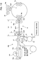
- a card rotating section (change section) 4 disposed below the card stacker 3 to rotate a card C supplied from the card stacker 3 a predetermined angle while nipping the card, an approximately horizontal linear card transport path CP to transport the card C from the card rotating section 4, a printing section PR provided below the card transport path CP in the substantially center portion of the card transport path CP to perform printing processing on the card C, and a control section that controls various sensors to acquire position information and the whole of the printing device 1.
- a card storage section 29 as a discharge stacker to store printed cards C.
- the card transport path CP is positioned in the vicinity immediately below the cover body 2A.
- the cover body 2A is arranged in the position for covering the card transport path CP and a part of the card rotating section 4, and the card stacker 3 is provided above the card transport path CP and the card rotating section 4.
- the card stacker 3 stores a plurality of blank cards C to be placed parallel in a laminate manner. In other words, the cards C are stored inside the card stacker 3 so that the thickness direction is aligned along the approximately horizontal direction.
- a stacker side plate 26 In a position near the other end portion of the cover body 2A in the card stacker 3 is disposed a stacker side plate 26 having a medium feed opening 107 ( FIG. 9 ) to permit the passage of only a single card C.
- Under the stacker side plate 26 on the side opposite to the card stacker 3 is disposed a card supply roller 18 in press-contact.
- the card supply roller 18 rotates and thereby sends out the card C positioned on the outermost side on a card-by-card basis among a plurality of blank cards C stored in the card stacker 3.
- the card support roller 18 comes into contact with the card C through a sending-out opening provided in the stacker side plate 26.
- a supply path SP to supply the card C toward the card rotating section 4.
- a first card transport roller pair comprised of a transport roller 19a disposed on one side (left side in FIG. 1 ) of the supplied card C, and a driven roller disposed on the other side (right side in FIG. 1 ).
- the first card transport roller pair is comprised of cleaning rollers having adhesion on their surface to clean the surface of the card C.
- a cleaner roller 30 is disposed in press-contact.
- the surface is coated with a substance having stronger adhesion than the first card transport roller pair to clean the surface of the driven roller (eventually, the transported card C).
- a card locating section 15a is disposed in the vicinity of the card rotating section 4 on the downstream side of the first card transport roller pair in the supply path SP.
- the sensor is capable of being formed of a transmission integral type or reflective integral type, and is to detect a card end of the card C transported on the supply path SP.
- the card rotating section 4 is disposed below the first card transport roller pair, and inside a rotating frame axially supported by the device housing 2 to be turntable and rotatable are disposed two roller pairs that nip the opposite ends of the card C, and a card guide (not shown) to guide the card C in between two roller pairs.
- the card rotating section 4 is capable of reversing or changing the transport direction of the card held between the pinch roller pairs.
- entire rotation of the card rotating section 4 and rotation of the roller pairs is driven independently.
- one roller of the roller pair is a driving roller
- the other roller is a driven roller.
- a magnetic write section (second recording section) 23 that magnetically recording information on a magnetic stripe while reading the recorded magnetic information to verify (confirm recording) when the card C is a magnetic card
- an IC write section (first recording section) 24 that stores electronic information in an incorporated non-contact type IC while reading the stored electronic information to verify when the card C is an IC card
- an eject box 25 error discharge outlet
- a barcode write section (third recording section) 28 is disposed to add barcode information while reading the added barcode information to verify when the card C is provided with a barcode.
- a receiving opening of the magnetic write section 23 is disposed on the side opposite to the card stacker 3 in the card rotating section 4, on an extension of the supply path SP that supplies the card C toward the card rotating section 4 from the supply stacker 3.
- the medium feed opening 107 of the stacker side plate 26, the card rotating section 4 and the magnetic write section 23 are disposed linearly.
- a card locating sensor 15d is disposed in the vicinity of the card rotating section 4 in the transport path toward the receiving opening of the magnetic write section 23.
- the IC write section 24 is disposed in between the card transport path CP and the card stacker 3 i.e. above the card transport path CP and below the card stacker 3.
- the IC write section 24 is disposed in between the printing section PR (more specifically, image transfer section, described later specifically) and the card rotating section 4.
- a card locating sensor 15b is disposed in the vicinity of the card rotating section 4 in the transport path toward the IC write section 24.
- the eject box 25 is disposed on the side opposite to the IC write section 24 in the card rotating section 4, and the IC write section 24, the card rotating section 4 and the eject box 25 are disposed linearly.
- the barcode write section 28 is disposed on an extension of the card transport path CP of the card rotating section 4.
- each of the card locating sensors 15b, 15d is capable of being formed of a transmission integral type or reflective integral type as in the above-mentioned card locating sensor 15a.
- the card rotating section 4 changes or reverses the transport direction of the card C nipped by two pinch roller pairs.
- the card C is positioned toward the magnetic write section 23, IC write section 24, barcode write section 28, receiving opening of the eject box 25 and card transport path CP by the card rotating section 4.
- the magnetic write section 23, IC write section 24 and barcode write section 28 perform recording processing of respective information on the card C with the card held at its one end portion by the card rotating section 4 (one pinch roller pair).
- three rotation position sensors are provided on the supply path SP side, the IC write section 24 side and the card transport path CP side, respectively.
- the position sensors on the IC write section 24 side and the card transport path CP side are capable of detecting the rotation position of the card C
- the position sensor on the supply path SP side is capable of detecting the rotation position of the card C or the rotation position of the driving roller in one pinch roller pair of two pinch roller pairs.
- a shield plate is disposed along the IC write section 24 to avoid the effect on the printing section PR and the sensor in the card transport path CP by electromagnetic waves generated in the IC write section 24.
- the card transport path CP has a second card transport roller pair, disposed on the downstream side of the card rotating section 4, comprised of a transport roller 19b disposed above the card transport path CP and a driven roller disposed below the path CP.
- a third card transport roller pair comprised of a transport roller 19c and a driven roller
- a platen roller 27 (constituting also the image transfer section, described later) on the downstream side of the third card transport roller pair
- a fourth card transport roller pair on the downstream side of the platen roller 27, comprised of a transport roller 19d and a driven roller
- a fifth card transport roller pair on the downstream side of the fourth card transport roller pair, comprised of a transport roller 19e and a driven roller.
- Standby space corresponding to a single card C is formed in between the second card transport roller pair (transport roller 19b) and the platen roller 27 (image transfer section PT).
- the card locating sensor 15c is arranged on the upstream side in the card transport direction of the second card transport roller pair i.e. in the vicinity of the card rotating section 4, a card locating section 16 is arranged in the downstream vicinity in the card transport direction of the third card transport roller pair, and a card locating sensor 17 is arranged in the downstream vicinity in the card transport direction of the fifth card transport roller pair in the most downstream position of the card transport path CP.
- each of these sensors is capable of being formed of a transmission integral type or reflective integral type, and detects the card end of the card C transported on the card transport path CP.
- the printing section PR is provided below the card transport path CP in the substantially center portion of the card transport path CP, and is provided in between the magnetic write section 23 disposed below the card rotating section 4 and the card storage section 29.
- the printing section PR is comprised of an image formation section PF having a thermal head 9 and platen roller 12 to form an image on an intermediate transfer film F, an intermediate transfer film transport section that transports the intermediate transfer film F, an ink ribbon transport section that transports an ink ribbon R, and the image transfer section PT that transfers the image formed on the intermediate transfer film F to the card C.
- the image transfer section PT is provided above the image formation section PF.
- the printing section PR is provided in between the magnetic write section 23 and the card storage section 29 below the card transport path CP, and therefore, the image transfer section PT provided above the image formation section PF is positioned in the substantially center portion of the card transport path CP.
- the platen roller 12 is axially supported to be rotatable in a fixed position.
- the thermal head 9 is configured to be able to travel between a separate position separate from the platen roller 12 and a printing position (state as shown in FIG. 1 ) in press-contact with the outer periphery of the platen roller 12 via the intermediate transfer film F and the ink ribbon R.
- the intermediate transfer film F and the ink ribbon R exist between the platen roller 12 and the thermal head 9.
- the image formation section PF selectively heats heating elements constituting the thermal head 9 for the ink ribbon R, and thereby forms an image (mirror image) on the intermediate transfer film F.
- the intermediate transfer film transport section has a film supply section 5 that supplies the intermediate transfer film F, a film winding section 6 that winds up the intermediate transfer film F, and a film main transport roller 13 that transports the intermediate transfer film F with high accuracy and is comprised thereof.
- the spool shaft of the film supply section 5 has a DC motor M1 capable of rotating forward and backward at high speed
- the spool shaft of the film winding section 6 has a DC motor M2 capable of rotating forward and backward at high speed
- the film main transport roller 13 has a stepping motor M3 capable of rotating forward and backward at high speed.
- the film winding section 6 is also used in managing back tension of the intermediate transfer film F in transferring the image formed on the intermediate transfer film F to the card C in the image transfer section PT.
- nip rollers 21, 22 (described specifically later) arranged in the film main transport roller 13 are separated from the film main transport roller 13.
- a plurality of rollers is arranged to change the transport direction in transporting the intermediate transfer film F between the film supply section 5 and the film winding section 6.
- the film main transport roller 13 are arranged two nip rollers 21, 22 movable between a nip position to come into press-contact with the film main transport roller 13 via the intermediate transfer film F and a separate position separate from the film main transport roller 13.
- the nip roller 21 is positioned on the upper side (the card transport path CP side) of the film main transport roller 13, and the nip roller 22 is positioned on the lower side.
- a driving source for moving such nip rollers 21, 22 between the nip position and the separate position for example, it is possible to use a magnetic plunger.
- a first mark detection sensor 10 is disposed to detect a mark (hereinafter, this mark is referred to as a first mark) formed on the intermediate transfer film F.
- the image formation section PF is disposed via a plurality of rollers.
- the thermal head 9 and the platen roller are disposed to be opposed.
- two rollers are arranged above the film main transport roller 13 to line in the approximately horizontal direction below the card transport path CP.
- the intermediate transfer film F is transported substantially horizontally between these two rollers (this portion in which the intermediate transfer film F is substantially horizontally transformed is referred to as a horizontal transport portion for the sake of convenience.)
- One of these two rollers is positioned on the downstream side in the card transport direction in the vicinity of the third card transport roller pair having the transport roller 19c, and the other roller is positioned on the upstream side in the card transport direction in the vicinity of the fourth card transport roller pair having the transport roller 19d.
- a transfer locating sensor 14 is disposed to detect a mark of the intermediate transfer film F in transferring the image formed on the intermediate transfer film F to the card.
- the first mark detection sensor 10 and the transfer locating sensor 14 are also capable of being formed of a transmission integral type or a reflective integral type.
- the intermediate transfer film F has a base film Fa, back coat layer Fb formed on the backside of the base film Fa, acceptance layer Fe for accepting ink, overcoat layer Fd for protecting the surface of the acceptance layer Fe, and release layer Fc formed on the frontside of the base film Fa to promote peeling, by heating, of the overcoat layer Fd and the acceptance layer Fe as one piece from the base film Fa.
- the back coat layer Fb, base film Fa, release layer Fc, overcoat layer Fd and acceptance layer Fe are laminated in this order.
- the intermediate transfer film F is transported so that the acceptance layer Fe side is opposed to the ink ribbon R, and that the back coat layer Fb side is able to come into contact with the platen roller 12.
- the above-mentioned first mark is formed linearly in the direction crossing the longitudinal direction of the intermediate transfer film F at predetermined intervals of one image area corresponding to the card C.
- the ink ribbon transport section has a ribbon supply section 7 that supplies the ink ribbon R, and a ribbon winding section 8 that winds up the ink ribbon R.
- DC motors M4, M5 capable of rotating forward and backward at high speed are used as a rotation driving source, respectively.
- a second mark detection sensor 11 to detect a mark (hereinafter, this mark is referred to as a second mark, and in this example, BK of the ink ribbon R is used as the second mark) formed on the ink ribbon R.
- the second mark detection sensor 11 is also capable of being formed of a transmission integral type or a reflective integral type.
- the position of the ink ribbon R is managed by detecting the second mark with the second mark detection sensor 11.
- the ink ribbon R is comprised of a plurality of colors as described below, and therefore, is transported in the substantially vertical direction to prevent the occurrence of misregistration (to improve printing quality) in image formation.
- the ink ribbon R has the shape of a film in a band shape with the width slightly longer than the length in the longitudinal direction of the card C.
- Ink of Y (Yellow), M (Magenta), C (Cyan) and BK (Black) is coated on the film and is repeated in a panel sequence.
- the image transfer section PT is disposed in the substantially center portion in the above-mentioned horizontal transport portion of the intermediate transfer film F.
- the platen roller 27 is disposed above the card transport path CP to support the card C in transferring the image formed on the intermediate transfer film F to the card C
- a heat roller 20 is disposed below the card transport path CP to be able to move forward and backward between a proceeding position and a retracted position with respect to the platen roller 27.
- the image is transferred to the card C from below the card transport path CP.
- a heating lamp not shown, for heating the intermediate transfer film F.
- the platen roller 27 and heating roller 20 are disposed to nip the card C and the intermediate transfer film F transported in the card transport path CP.
- To move the heating roller 20 forward and backward for example, it is possible to use a cam.
- a decurl roller DR to correct curling of the image-formed card C is disposed in between the fourth card transport roller 19d and the fifth card transport roller 19e above the card transport path CP.
- the decurl roller DR is disposed to be able to move forward and backward between a proceeding position and a retracted position with respect to the card transport path CP, and corrects curling of the card C due to heat of the incorporated heat source.
- the card storage section 29 is disposed on the side opposite to the card rotating section 4 of the card transport path CP, and has a box shape having the height of from the bottom position of the housing 2 to the height position of the card transport path CP.
- a shelf board to mount discharged cards C is provided to be movable in the vertical direction.
- Opposite end portions of a spring are respectively fixed the lower surface of the shelf board and the inner bottom of the card storage section 29.
- the cards C subjected to the printing processing or the like are stacked and stored to overlap. In other words, the cards C are stored in the card storage section 29 so that the thickness direction is aligned along the approximately vertical direction.
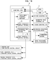
- a control section 40 has a microcomputer 40A that performs control processing on the printing device 1 and is comprised thereof.
- the microcomputer 40A is comprised of a CPU that operates on a high-speed clock as a central processing unit, ROM in which control operation of the printing device 1 is stored, RAM for working as a work area of the CPU, involatile memories such as a flash memory and EEPROM, and internal buses to connect the elements.
- the microcomputer 40A is connected to an external bus 40B.
- the external bus 40B is connected to each of a touch panel display operation control section 40C that controls display of a touch panel (input display section), not shown, and input command, a sensor control section 40D that controls signals from various sensors, a motor control section 40E that controls driving of each motor, an outside input/output interface 40F to communicate with an external device such as a host computer, a buffer memory 40G that temporarily stores image information and the like to print on the card C, and a thermal head control section 40H that controls heat energy to the thermal head 9.
- an actuator control section is also connected to control an actuator and the like for travel of the nip rollers 21, 22 between the nip position and the separate position, and travel of the decurl roller DR between the proceeding position and the retracted position.
- the printing device 1 operates by the command from the above-mentioned touch panel, and is also capable of operating by a command from the above-mentioned external device via the outside input/output interface 40F.
- the printing device 1 has a power supply section that supplies operation power to each of the above-mentioned sections, and a battery device (for example, button-type lithium ion battery) connected to the power supply section as a power supply to ensure operation time for writing required information in the involatile memory after supply of commercial power is shut off.
- a battery device for example, button-type lithium ion battery
- the operation of the printing device 1 of this Embodiment will be described next focusing on the CPU (hereinafter, referred to as the CPU) of the microcomputer 40A of the control section 40.
- the CPU expands programs and program data in the RAM from the ROM, monitors initial setting processing for positioning each of the above-mentioned components in the home position and output information from an empty sensor, not shown, thereby confirms that the cards C are stored in the card stacker 3, further monitors output information from the above-mentioned various sensors, and thereby confirms that the intermediate transfer film F and the ink ribbon R are installed.
- the CPU causes an alert to be sounded, displays the message on the above-mentioned touch panel, while in the case of operating by the command from the external device, notifying the external device of the message, performs confirmation processing to confirm whether everything is stored and installed, and transports the intermediate transfer film F and the ink ribbon R to the usable initial position by referring to the involatile memory.
- the buffer memory 40G of the control section 40 stores image information decomposed to three colors, Y, M and C, and control information received from the external device via the outside input/output interface 40F, the thermal head 9 is in the retracted position, and that a printing command is issued from the external device.
- the CPU waits for a printing command (transfer request), and when the printing command is issued, drives the motor M2 to start transport so that the film winding section 6 winds up the intermediate transfer film F, while driving the motor M5 to start transport so that the ink ribbon winding section 8 winds up the ink ribbon R.
- the first mark of the intermediate transfer film F passes through the first mark detection sensor 10, and is positioned on the upstream side in the intermediate transfer film transport direction in image formation (this position is referred to as an initial position of the intermediate transfer film F.)
- the thermal head 9 is positioned in the retracted position, the first mark is on the upstream side of the first mark detection sensor 10 in the transport direction in image formation, and the first mark detection sensor 10 does not detect the first mark yet (in the operation of feeding the start of the intermediate transfer film F in image formation).
- the front end portion of Y color of the ink ribbon R is positioned to correspond to the printing start position of the intermediate transfer film F (this position is referred to as an initial position of the ink ribbon R.)
- the initial positions of the intermediate transfer film F and the ink ribbon R are set so that the distance from a press-contact position in which the thermal head 9 and the platen 12 are in press-contact to the image formation position in the initial position of the intermediate transfer film F is the same as the distance from the press-contact position to the front end portion of Y color of the ink ribbon R.
- the thermal head 9 is moved to the printing position. Also in this state, the first mark is on the upstream side of the first mark detection sensor 10 in the transport direction in image formation, and the first mark detection sensor 10 does not detect the first mark yet.
- the CPU transports the intermediate transfer film F and the ink ribbon R (in the transport direction in image formation), while monitoring output information (output signal) from the first mark detection sensor 10, thereby determines whether or not the first mark detection sensor 10 detects the first mark, and continues monitoring in a negative determination, while performing feeding for transporting each of the intermediate transfer film F and the ink ribbon R by a predetermined distance in a positive determination.
- the intermediate transfer film F and the ink ribbon R are transported at the same time by the same distance.
- the intermediate transfer film F (in a strict sense, the position of the intermediate transfer film F corresponding to one image area targeted for image formation) is on the upstream side from the printing start position (position to start formation of an image on the intermediate transfer film F by heating selectively heating elements of the thermal heat 9 for the ink ribbon R), and the preliminary passage of current is started to the thermal head 9.
- each heating element is heated to the temperature that does not allow ink of the ink ribbon R to be transferred to the intermediate transfer film F i.e. near the upper limit of the temperature that disables coloring.
- Such a preliminary passage of current is performed to prevent the printing quality from deteriorating due to the fact that the heating elements cannot follow when the heating elements constituting the thermal head 9 are selectively heated immediately after the intermediate transfer film F arrives at the printing start position.
- the CPU still continues to transport the intermediate transfer film F and the ink ribbon R, and when both of the intermediate transfer film F and the ink ribbon R arrive at the printing start position (the motor control section 40E performs time management on the DC motors, while performing pulse management on the stepping motor, and it is thereby possible to grasp that the intermediate transfer film F arrives at the initial printing position), selectively heats the heating elements constituting the thermal head 9 to start image formation on the intermediate transfer film F.
- the ink ribbon R is disposed in order of Y, M, C and BK, in a strict sense, the feeding position of the intermediate transfer film F corresponding to one image area and the feeding position of Y of the ink ribbon R arrive at the printing start position. In addition, such registering processing will be described later.
- the intermediate transfer film F and the ink ribbon R are transported continuously, and image transfer to the intermediate transfer film F corresponding to one image area is finished.
- Shown herein is a printing example using a single color of BK.
- the thermal head 9 is moved to the retracted position, the output information of the first mark detection sensor 10 and the second mark detection sensor 11 is monitored, and the intermediate transfer film F is thereby transported backward so that the first mark reaches the upstream side in the transport direction in image formation onto the intermediate transfer film F from the location position of the first mark detection sensor 10, while the ink ribbon R is transported backward so that the front end of ink of the next color (M color) of the ink ribbon R corresponds to the initial position of the intermediate transfer film F.
- M color next color
- backward transport is performed until the position of the intermediate transfer film F of one image area and the position of ink (M) of the next color of the ink ribbon R arrive at the initial positions.
- the distance from the initial position of the intermediate transfer film F to the printing start position is calculated so that the position of the intermediate transfer film F of one image area and the position of ink (M) of the next color of the ink ribbon R coincide with the printing start position, and backward transport is performed corresponding to the distance.
- the distance calculation will be described.
- Y is printed, in a state in which the intermediate transfer film F and the ink ribbon R arrive at the printing start position, in order for the printing start position of the intermediate transfer film F and the printing start position of Y to coincide with each other, the position of Y of the ink ribbon is registered in the initial position such that the first mark is on the upstream side of the first mark detection sensor 10 in the transport direction in image formation, and that the first mark detection sensor 10 does not detect the first mark yet.
- the distance from the initial position of the intermediate transfer film F to the printing start position is beforehand calculated, and the initial position of the ink ribbon R is determined according to the distance.
- the initial position of the ink ribbon R in printing M is determined so that the printing position of M and the printing start position of the intermediate transfer film coincide with each other.
- Next C is in the same manner.
- the absolute position of the ink ribbon R is managed by detecting BK using the second mark detection sensor 11, the printing quality does not deteriorate unless feeding of the intermediate transfer film F is misregistered.
- the CPU transports the image formed on the intermediate transfer film F to the image transfer section PT, and executes transfer processing for transferring the image to the card C in the image formation section PF.
- the CPU drives and rotates the card supply roller 18, and feeds the blank card C to the supply path SP from the card stacker 3.
- the first card transport roller pair disposed on the supply path SP is driven to rotate concurrently with driving of the card supply roller 18, and cleans the printing surface side of the card C, while promoting transport to the card rotating section 4 on the supply path SP. Further, as shown in FIG.
- the CPU concurrently with rotation driving of the first card transport roller pair, the CPU rotates the card rotating section 4, and positions two pinch roller pairs to be positioned on the extension of the supply path SP (this position is referred to as an initial position of the card rotating section 4.)
- the CPU halts rotation driving of the card rotating section 4.
- the card locating sensor 15a provided in the vicinity of the card rotating section 4 detects the front end in the transport direction of the card C
- the CPU halts rotation driving of the card supply roller 18, while driving and rotating two pinch roller pairs in the card rotating section 4.
- the CPU halts rotation driving of the first card transport roller pair and two pinch roller pairs in the card rotating section 4.
- the CPU refers to the control information stored in the buffer memory 40, determines whether the card C is a magnetic card or an IC card, and corresponding to the determination result, rotates the card rotating section 4 a predetermined angle to feed the card C to the magnetic write section 23 or IC write section 24.
- the CPU drives two pinch roller pairs in the card rotating section 4.
- the CPU halts rotation driving of the pinch roller pairs.
- the magnetic write section 23 records the magnetic information and executes verification.
- the CPU drives two pinch roller pairs in the card rotating section 4.
- the CPU halts rotation driving of the pinch roller pairs.
- the IC write section 24 records the electronic information and executes verification.
- the CPU refers to the control information stored in the buffer memory 40, determines whether or not to need to record barcode information on the card C, and corresponding to the determination result, rotates the card rotating section 4 a predetermined angle to feed the card C to the barcode write section 28.
- the CPU drives two pinch roller pairs in the card rotating section 4.
- the CPU halts rotation driving of the pinch roller pairs.
- the barcode write section 28 adds the barcode information and executes verification.
- the CPU determines whether to transport the card C to the eject box 25 or to the second card transport roller side on the card transport path CP. In determining to transport to the eject box 25, at the time the card C is detected by the position sensor provided on the IC write section 24 side of the card rotating section 4 and the card transport direction coincides with the direction of the IC write section 24, the CPU drives two pinch roller pairs in the card rotating section 4 to transport to the eject box 25, and then, performs the above-mentioned processing again from supply of the blank card C by the card supply roller 18.
- the CPU determines to transport to the second card transport roller side on the card transport path CP
- the CPU drives two pinch roller pairs in the card rotating section 4, and transports the card C to the card transport path CP.
- the card locating sensor 15c disposed in the vicinity of the card rotating section 4 detects the front end in the transport direction of the card C
- the CPU drives and rotates the transport roller arranged on the card transport path CP.
- the CPU halts rotation driving of the pinch roller pairs of the card rotating section 4, and halts the transport roller arranged on the card transport path CP.
- the card C is once nipped by the second and third card transport roller pairs.
- the CPU moves the nip rollers 21, 22 to the nip position, and transports the intermediate transfer film F such that the image of one image area is formed in the image formation section PF to the image transfer section PT.
- This transport is performed by driving the motor M1 and stepping motor M3 while checking detection of the first mark by the transfer locating sensor 14.
- the CPU heats the heating lamp of the heat roller 20 to move forward to the proceeding position.
- the CPU drives and rotates the transport roller arranged on the card transport path CP, and transports the card C nipped by the second and third card transport roller pairs to the image transfer section PT.
- the intermediate transfer film F and the card C are transported to the image transfer section PT at the same speed, the card C is supported on its upper side (backside) by the rotating platen roller 27, while being heated on its lower side (frontside) by the heat lamp 20 via the image formation position of one image area of the intermediate transfer film F, and the image of one image area of the intermediate transfer film F is thereby transferred to the card C.
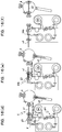
- the card C After finishing image transfer, the card C is still transported to the downstream side on the card transport path CP, and when the card locating sensor 17 detects the front end in the transport direction of the card C, the CPU halts rotation driving of the transport roller arranged on the card transport path CP. By this means, the card C is once nipped by the fourth and fifth card transport roller pairs. In this state, the decurl roller DR is positioned in the proceeding position, and corrects skew of the card C. After positioning the decurl roller DR in the retracted position, the CPU drives the transport roller arranged on the card transport path CP in the backward rotation direction, and transports backward the card C to the card rotating section 4 on the card transport path CP.
- the CPU drives and rotates the pinch roller pairs in the card rotating section 4.
- the CPU halts rotation driving of the transport roller arranged on the card transport path CP and the pinch roller pairs in the card rotating section 4.
- the CPU rotates the card rotating section 4 nipping the card C 180 degrees.
- the card C is reversed and positioned with the lower side (frontside) turned to the backside.
- the card C is transported to the second card transport roller pair side, and nipped by the second and third card transport roller pairs, and subsequent control is already disrobed and therefore, omitted.
- the processing content differs from the content of the printing processing as described already, but is the same except the respect, and the description is omitted. Further, the processing differs in the respects that the blank card C is not supplied from the card stacker 3 in the transfer processing, and that magnetic or electronic information or barcode information is not recorded on the card C. Since the card is already nipped by the second and third transport roller pairs, it is essential only that the image transfer section PT transfers the image formed on the intermediate transfer film F to the backside, and the description is redundant, and is omitted.
- the card C After finishing image transfer to the backside, the card C is still transported to the downstream side on the card transport path CP, and is discharged outside the housing 2 via a discharge outlet formed in the outer surface of the housing 2. In this position is disposed the card storage section 29 that stores the cards C subjected to the printing and information recording processing.
- the cards C discharged from the housing 2 are stacked to overlap on the shelf board inside the card storage section 29.
- the cards C are stored in the card storage section 29 while being aligned.
- the shelf board When the card is not stored in the card storage section 29, the shelf board is positioned in the upper portion inside the card storage section 29 by biasing of the spring.
- the CPU After a lapse of predetermined time since the card locating sensor 17 detects the card rear end in the transport direction, the CPU halts rotation driving of the transport roller arranged on the card transport path CP and two pinch roller pairs of the card rotating section 4, drives the motor M1 to rewind the intermediate transfer film F to a predetermined position, and stores the position information of an unused image area of the intermediate transfer film F in the nonvolatile memory. By this means, printing on a single card C is finished.
- the card stacker 3 is provided on the top side of the cover body 2A disposed at the top of the housing 2. Therefore, it is possible to increase the card stacker 3 corresponding to the length of the cover body 2A, and by storing the cards C to be placed parallel in a laminate manner inside the card stacker 3, it is possible to increase the supply number of cards C.
- the card transport path CP is disposed below the cover body 2A, and the printing section PR is disposed below the card transport path CP. Therefore, since the card transport path CP is positioned in the upper portion inside the housing 2, it is possible to increase the height of the card storage section 29 disposed outside the housing 2 on the most downstream side of the card transport path CP.
- the card storage section 29 it is possible to store all cards C, which are supplied from the card stacker 3 and are subjected to processing of printing, information recording and the like, in the card storage section 29, and it is thereby possible to support large-amount discharge in response to large-amount supply. Further, since the printing section PR is disposed below the card transport path CP and the card stacker 3 is provided on the top side of the cover body 2A, it is possible to decrease the size of the entire device enabling large-amount processing.
- the card stacker 3 is configured to be detachable and attachable with respect to the cover body 2A. Therefore, by preparing card stackers 3 for each type and/or size of card C, operation for replacing cards C to supply is made ease, and it is possible to easily support various kinds of cards C. Furthermore, since the printing section PR is provided below the card transport path CP, the card transport path CP is disposed in the vicinity immediately below the cover body 2A. Therefore, by removing the card stacker 3 from the cover body 2A and opening the cover body 2A, it is possible to access the card transport path CP from the opening at the top of the cover body 2A with ease (see FIG. 4 ).
- the printing section PR is provided in between the magnetic write section 23 and the card storage section 29, the image transfer section PT in which a jam tends to occur frequently is disposed in the substantially center portion of the card transport path CP, and it is thereby possible to improve efficiency of jam clearing operation. Furthermore, since the card transport path CP is disposed in the vicinity immediately below the cover body 2A, the need for removing the ink ribbon R and/or intermediate transfer film F is eliminated in jam clearing, and it is thereby possible to avoid the adhesion of dust to the ink ribbon R and intermediate transfer film F.
- the IC write section 24 is disposed above the card transport path CP, while being below the card stacker 3 in between the image transfer section PT and the card rotating section 4. Therefore, it is possible to effectively use space inside the housing 2, and to contribute to miniaturization of the entire device. In this arrangement, even when a jam occurs in the image transfer section PT, it is possible to avoid interference of the IC write section 24 in jam clearing operation.
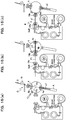
- the recording processing is performed with one end of the card C held by the pinch roller pair in the card rotating section 4, in performing the recording processing of magnetic information by the magnetic write section 23, recording processing of electronic information by the IC write section 24, and recording processing of barcode information by the barcode write section 28 (also see FIG. 6 ). Therefore, it is not necessary to provide driving mechanisms in the magnetic write section 23, IC write section 24 and barcode write section 28. By this means, it is possible to contribute to miniaturization of the entire device, and to reduce energy consumption corresponding to no need of the driving mechanisms. Further, in the printing device 1, the barcode write section 28 is disposed on the extension of the card transport path CP outside the housing 2 on the card rotating section 4 side. Therefore, when the barcode information is not needed, it is possible to remove the barcode write section 28, and to improve versatility.
- the magnetic write section 23 is disposed on the extension of the supply path SP on the side opposite to the card stacker 3 in the card rotating section 4 i.e. below the card rotating section 4. Therefore, when the card C is positioned toward the magnetic write section 23 in recording the magnetic information on the card C, it is possible to share the position sensor provided on the supply path SP side of the card rotating section 4 (also see FIG. 5 ). Further, the IC write section 24, card rotating section 4 and eject box 25 are disposed linearly, and the eject box 25 is disposed on the side opposite to the IC write section 24 in the card rotating section 4.
- the printing device 1 of this Embodiment standby space corresponding to a single card C is formed on the card transport path CP between the second card transport roller pair having the transport roller 19b and the platen roller 27 constituting the image transfer section PT. Therefore, when the image transfer section PT executes image transfer, it is possible to perform the recording processing of magnetic information or electronic information in the magnetic write section 23 or IC write section 24 by rotation of the card rotating section 4, and therefore, it is made possible to perform parallel processing of the printing processing and the recording processing.
- this Embodiment shows the example in which the barcode write section 28 is disposed on the extension of the card transport path CP, but the invention is not limited thereto.
- the recording processing of barcode information for example, it is possible to configure so that electronic information is stored in an IC incorporated into the card C.
- the IC write section 24 performs recording processing on a non-contact type IC, while recording processing is performed on a contact type IC, and it is thus possible to use separately.
- this Embodiment shows the example in which the printing section PR performs the printing processing after the recording processing in the magnetic write section 23 and IC write section 24, but the invention is not limited thereto, and the sequence of the recording processing and the printing processing may be changed to perform.
- the invention is not limited thereto, and the sequence of the recording processing and the printing processing may be changed to perform.
- by controlling the blank card C transported from the card stacker 3 to the card rotating section 4 to be fed onto the card transport path CP it is possible to perform the printing processing before the recording processing.
- this Embodiment shows the example in which the film winding section 6 is disposed below the film supply section 5, but the invention is not limited thereto, and the positions of the film supply section 5 and the film winding section 6 may be interchanged. Still furthermore, the example is shown in which the ribbon winding section 8 is disposed above the ribbon supply section 8, but the invention is not limited thereto, and it is naturally possible to interchange the positions of the ribbon winding section 8 and the ribbon supply section 7. Moreover, this Embodiment shows the example of using DC motors respectively in the supply sections and winding sections of the intermediate transfer film F and the ink ribbon R, and it is also possible to use a common DC motor in the supply section and the winding section with a gear mechanism.
- Embodiment 2 according to the invention will be described next with reference to FIGs. 7 to 18 .
- Embodiment 2 it is possible to store a large amount of cards in storing a plurality of cards in a medium feed section, while facilitating operation for adding cards and operation for removing a failed card.
- Embodiment 2 in performing a plurality of types of processing of information recording and image formation on a recording medium, it is possible to perform parallel processing on a plurality of cards, while miniaturizing the transport path of recording media, information recording mechanism and image formation mechanism.
- Embodiment 2 components having the same functions as in Embodiment 1 are assigned the same reference numerals, but sensors such as card locating sensors 15a to 15e, ink ribbon R mark detection sensor 11 and transfer locating sensor 14 in Embodiment 1 are changed to numerals of Se1 to Se12 in Embodiment 2 to describe.
- Embodiment 2 according to the invention will be described below.
- FIG. 12 is a conceptual diagram showing a layout configuration of a device of FIG. 7 , and according to FIG. 12 , a layout of each configuration will be described.
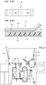
- a card supply section CA In the device housing 2 are disposed a card supply section CA, and the card rotating section 4 for changing the direction of a card C as a printing medium fed from the card supply section CA.
- a first transport path P1 On the downstream side of the card rotating section 4 are disposed a first transport path P1 for carrying the card in the first direction, and a second transport path P2 for carrying the card C in the second direction.
- a third transport path P3 for transporting the card C in the third transport direction is disposed separately from the second transport path P2.
- the card supply section CA is comprised of the card stacker 3 provided with a card storage section for aligning and storing a plurality of cards C in a standing posture (see FIGs. 7 to 9 ) forward and backward, and a supply opening for feeding the card, and the direction for sending out the card C (direction of arrow X in FIG. 2 ), and the card transport direction (direction of arrow Y in FIG. 2 ) of the first transport path P1 are disposed in the substantially parallel directions in mutually opposite directions.
- the card stacker 3 positioned in the upper portion of FIG. 2 and the first transport path P1 are disposed parallel in lower and upper portions, the storage area of cards C and image transfer mechanism (transfer platen 27 and standby section E described later) are laid parallel in upper and lower portions, and it is intended to make the device compact.
- the card rotating section 4 is provided below and adjacent to the card supply section CA, and is disposed on one end side (right side in FIG. 12 ) of the device housing 2. Then, on the downstream side of the card rotating section 4, the first transport path P1 is disposed in the approximately horizontal direction, and the second transport path P2 is disposed in the approximately vertical direction.
- the first and second transport paths P1 and P2 are disposed in different angular directions, are preferably disposed in the angular range of 90 degrees to 180 degrees as shown in the figure, and are set in an appropriate angular range in consideration of densely configuration of paths.
- the standby section E is comprised of the transport roller 19b, its driven roller (hereinafter, referred to as a transport roller pair 19b), transport roller 19c and its driven roller (hereinafter, transport roller pair 19c) at a distance Ld shorter than the transport length Lc of the card C.
- the printing section PR is comprised of the transfer platen (in the device shown in the figure, platen roller 27), supports the card C to back up, and transfers an image to the surface (the lower surface in FIG. 13 ). In the platen, the heat roller 20 to transfer is disposed to move up and down between a standby position separate from the card C and an operating position to come into contact with the card C.
- the transfer film F is provided between the transfer platen roller 27 and the heat roller 20.
- the device as shown in the figure is provided with a transfer film cassette 50, as described later, and the transfer film cassette 50 is disposed below the first transport path P1 together with a ribbon cassette 42, described later.
- the transfer film F stored in the transfer film cassette 50 is provided with a film path P4 to run between the transfer platen 27 and the image formation section PF.
- the image transfer section PT is disposed in the arrangement space of the standby section E of the first transport path P1 below the transport path.
- the image formation section PF is comprised of the platen roller 12 for image formation and the thermal head 9 disposed opposite the platen roller, and is configured so that the ink ribbon R runs in between the roller and head.
- the configuration of the ink ribbon will be described in the ribbon cassette, described later.
- the card rotating section 4 and the standby section E of the first transport path P1 are positioned in the upper portion, and the second transport path P2 and an upper recording area of a magnetic recording mechanism and the like, described later, of the path are positioned in the side portion. Then, the ribbon cassette 42 and the transfer film cassette 50 are disposed in this order in between the card rotating section 4 of the first transport path P1 and the image transfer section PT.
- the first transport path P1 and the second transport path P2 are disposed in the different angular directions via the card rotating section 4 as described above, and the ribbon cassette 42 and the transfer film cassette 50 are disposed in an area surrounded by both paths to form an intermediate transfer area. Then, the standby section E is disposed in the first transport path between the card rotating section 4 and the printing section PR, and the image formation section PF is disposed below the section E.
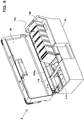
- the card stacker 3 of the card supply section CA is configured in a cassette form (card cassette), and is inserted in a stacker installation opening formed in the device housing 2 to enable load and unload. Accordingly, by pulling up the card stacker 3 with a grip, not shown, the card stacker 3 is detachable upward (in the substantially same direction as the card supply direction, described later), and when a card jam occurs in the supply section, it is possible to clear the jam by removing the card stacker 3. As shown in FIG.
- the card stacker 3 is comprised of a box-shaped housing 3a (hereinafter, referred to as the "housing"), and a card storage section 104 provided inside the housing.
- the card storage section 104 (printing media storage section) is comprised of storage space adapted to card dimensions for enabling a plurality of cards that are printing media to be aligned and stored in a standing posture.
- the card storage section 104 is provided with an opening portion 104a to load and unload the card C in the upper portion shown in the figure, and is hinge-coupled to an open/close cover 3b to open and close the opening portion.
- the card storage section 104 is configured in a space form to align the cards C from one end (left end viewed in the figure) to the other end (right end) to store in a standing posture.
- a card placement surface 105 as the printing media placement surface to place the cards C in a standing posture
- a card lock surface 106 as the printing media lock surface that locks the front card C.
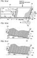
- the card placement surface 105 and the card lock surface 106 hold the cards in a forward-tilting posture. Therefore, the card placement surface 105 is comprised of an inclined surface 105a or step surfaces 105b with a height difference ⁇ d in the sending direction (arrow X direction). Further, the card lock surface 106 is formed of an inclined surface 106a that locks the card C in a forward-tilting posture. In other words, the sending direction is the direction toward the card lock surface 106 in the card collection direction.
- the card placement surface using a plurality of step surfaces lowering stepwise in the sending direction as in this Embodiment, the card lower end edge placed in a standing posture is locked by the step portion, and the card does not fall in a forward-tilting posture direction.
- the card stacker 3 is removed to add cards C, the cards do not fall, and addition operation is made ease.
- FIG. 9(a) is a configuration view of the card section 104
- FIG. 9(b) shows the case of configuring the card placement surface 105 using the step surfaces 105b
- FIG. 9(c) shows the case of configuring the surface 105 using the inclined surface 105a
- the height difference ⁇ d lowering in the sending direction X is formed in both cases
- the inclined surface 106a of the card lock surface 106 is formed at an angle ⁇ adapted to the height difference ⁇ d.
- the card lock surface 106 does not need to be always formed of a flat surface, and may be formed of protrusions that lock the card front in a forward-tilting posture.
- protrusions contacting the card upper portion and protrusions contacting the card lower portion are provided with a height difference.
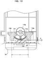
- the card storage section 104 is provided with the medium feed opening 107 at its front end portion in the sending direction.
- the medium feed opening 107 is comprised of an opening for enabling the front card C to be carried outside the housing. Then, as shown in FIG. 9 , the opening 107 is formed in the shape of a slit for carrying out the front card C locked in a forward-tilting posture by the card lock surface 106 from the bottom of the housing 3a to the outside.
- the medium feed opening 107 has a slit thickness (d) adapted to the card thickness and width (e) as shown in FIG. 10 , and is formed in the slit thickness (d) for allowing only the front card C to pass through.
- the medium feed opening 107 constitutes separating means for separating the card C on a card-by-card basis in sending the card C with a pick-up roller 18, described later.
- separation pads 108a, 108b at card opposite end portions (or may be in one center portion) and an idle roller 109 are disposed opposite each other and form the separating means.
- the separation pad 108a (108b) is made of an elastic material such as rubber with a high coefficient of friction, and separates the card C in between the pad and the idle roller 109.
- the separation pads 108a, 108b separate two sheets or more passing through the above-mentioned slit thickness (d).
- the slit thickness (d) is configured to be adjustable corresponding to the thickness of the card C to store.
- the separation pads 108a, 108b hold the card C, and the card does not thereby run out.
- the adjustment mechanism as shown in the figure is formed of an eccentric cam 110, the cam surface 110a is formed to be able to vary the slit thickness (d) shown in the figure gradually, and the rotation angle is set with an adjustment knob 110b.
- the card storage section 104 is provided with a picker opening 111 that engages the pick-up means 18, described later, in the surface of the front card.
- the picker opening 111 is formed as an opening that engages the pick-up roller 18, described later, in the front card C.
- the picker opening 111 is disposed in between the card lock surface 106 as described above and the medium feed opening 107, and the card lock surface 106, picker opening 111 and medium feed opening 107 are disposed in this order along the card feed direction Y (shown by the arrow in FIG. 9 ).
- the picker opening 111 and the medium feed opening 107 are disposed with respect to the card lock surface 106 that supports the card C in a forward-tilting posture, and therefore, triangular space Ar as shown in FIG. 9 is formed.
- the pick-up roller 18, described later inside the space, it is possible to reduce the space of the device.
- the card storage section 104 is provided with a support member 112 that is a support member for supporting the back of the backmost card stored in the card storage section 104.
- the support member 112 is comprised of a member such as a plate member and a block member that press-supports the back of the card C, and sends out the cards C, which are aligned and stored in a standing posture, in the sending direction X.
- the support member 112 is supported slidably in the sending direction X by a guide groove 13 formed on the inner wall of the housing 3a.
- the support member 112 is integrally provided with an operation knob 114, and by operating the knob, is movable between an operating position for supporting the card C and a retracted position retracted therefrom.
- the support member 112 is provided with a biasing means 115 for biasing the member 112 in the sending direction of the card C.
- the biasing means 115 shown in the figure is comprised of a spring, and one end 115a of the spring is fixed to the housing 3a, while the other end 115b is fixed to the support member 112.
- "115P" shown in the figure denotes a pulley that supports the spring in a U-turn shape. Then, as shown in FIG. 11 , the biasing means 115 is disposed on the side surface portion of the housing 3a.
- a taper surface 112x is provided in the upper portion of the support member 112 so as to create a gap between the member and the card C. Accordingly, in the case of adding the low number of cards C, with the support member 112 pressing the card C, it is possible to add the cards C by inserting the cards in the tapered surface, and it is not necessary to move the support member 112 with the operation knob 114.
- the operation knob 114 is hinge-coupled to the support member 112 to be swingable, and the member of the device is locked in a latch groove 116 as shown in FIG. 11 .
- the latch groove 116 By locking in the latch groove 116, the support member 112 is held in the retracted position.
- the operation knob 114 locked in the latch groove 116 inhibits close of the open/close cover 3b in the dashed-line state in FIG. 8 .
- the carry-in roller 19a is provided with adhesion
- the cleaning roller 30 is further provided with stronger adhesion
- the carry-in roller 19a thereby removes dust from the card C
- the cleaning roller 30 further removes dust of the carry-in roller 19a.
- the card rotating section 4 as a change section is disposed, and is configured to enable the card C fed from the card stacker 3 to turn in a predetermined angular direction.
- the card rotating section 4 disposed on the downstream side of the card supply section CA. As shown in FIG. 7 , the carry-in roller 19a is disposed on the downstream side of the medium feed opening 107 of the card stacker 3. Then, the card C sent out of the card stacker 3 is fed to the card rotating section 4 by the carry-in roller 19a.
- the card rotating section 4 is comprised of a rotating frame axially supported by the device frame (not shown) to be rotatable, and a pair or a plurality of roller pairs supported by the frame.
- roller pairs 4a, 4b spaced a distance in front and in the back are axially supported by the rotating frame to be rotatable.
- the rotating frame turns in a predetermined angular direction by a turn motor (pulse motor or the like), and the roller pairs attached to the frame are configured to rotate in forward and backward directions with a transport motor.
- the driving mechanism is not shown in the figure, but for example, it is configured that a single pulse motor is used and that the turn of the rotating frame and rotation of roller pairs are switched using a clutch.
- the card C prepared in the card stacker 3 is sent out by the card supply roller 18, separated on a card-by-card basis by the separation gap of the medium feed opening 107, and fed to the card rotating section 4 on the downstream side. Then, the card rotating section 4 carries the card C into the unit by the roller pairs 4a, 4b, and changes the position in the predetermined angular direction while nipping the card by the roller pairs.
- the first transport path P1, second transport path P2 and third transport path P3 described later are disposed in respective angular directions.
- a magnetic recording unit 23 is incorporated into the second transport path P2, and records magnetic information on a magnetic stripe of the card C fed from the card rotating section 4.
- the magnetic recording unit 23 shown in the figure is comprised of a read/write head, and is configured to read the recorded information to determine correct or wrong concurrently with recording of the magnetic information.
- a non-contact IC recording unit 127 is incorporated into the third transport path P3, and records information on an IC that is beforehand built-in the recording medium.
- the eject box (reject stacker) 25 and barcode reader are disposed in the outer region of the card rotating section 4 in the turn direction thereof.
- the barcode reader is a unit to read a barcode printed in the image formation section PF, described later, and determine correct or wrong (error determination).
- roller pairs 4a, 4b move the card C, of which position is changed to the predetermined angular direction by the card rotating section 4, to the recording unit, it is made possible to input data on the card magnetically or electronically. Further, when a recording error occurs in any of the data input units, the card is carried out to the eject box (reject stacker) 25.
- the first transport path P1 is disposed on the downstream side of the card rotating section 4.
- the printing section PR for transferring an image to the intermediate transfer film F is disposed in the first transport path P1, and forms the image on the card C fed from the card rotating section 4.
- the roller pairs (which may be belts) 19b, 19c are disposed on the upstream side of the printing section PR in the first transport path P1, and are coupled to a transport motor, not shown.
- a group of transport roller pairs 19b, 19c is configured to enable switching between forward rotation and backward rotation, and is able to transport the card C from the printing section PR to the card rotating section 4, concurrently with transport of the card C from the card rotating section 4 to the printing section PR.
- the standby section E is disposed on the upstream side of the printing section PR.
- the transport roller pair 19b and the transport roller pair 19c are disposed at a distance Ld shorter than the length Lc in the transport direction of the card C.
- the card C is held by the group of transport roller pairs 19b, 19c spaced a distance in front and in the back, and waits temporarily. Therefore, transmission clutches (not shown) are provided in between the transport roller pairs 19b, 19c and the driving motor, and by turning the clutches to the OFF state, it is possible to halt the card C to wait.
- the transport roller pairs 19b, 19c are disposed in between the card rotating section 4 and the printing section PR to transfer, described later. Further, the sensor Se5 to detect carry-in and carrying-out of the card C with respect to the card rotating section 4 is disposed in between the card rotating section 4 and the transport roller pair 19b, and is capable of detecting the presence or absence of the card C inside the card rotating section 4.
- the card front end exists on the upstream side from the heat roller 20, described later.
- the front end portion of the waiting card C is not heated by the heat roller 20, there is no fear that fluctuations occur in the image transferred to the card C.
- the transfer film F since the standby section E is disposed on the upstream side of the printing section PR, the transfer film F is not damaged.
- the card rear end exists in between the transport roller pair 19b and the sensor Se5 (in the state of passing through the sensor Se5). Accordingly, even when the card rotating section 4 turns during standby of the card, the section 4 does not come into contact with the card C.
- the standby section E in the first transport path P1 between the card rotating section 4 and the printing section PR, it is possible to control separately a job for recording the magnetic information in the second transport path P2 and a job for recording the IC information in the third transport path P3 positioned on the upstream side, and a job for forming an image in the first transport path P1 positioned on the downstream side.
- the standby position E is provided in between the card rotating section 4 and the printing section PR in the first transport path for forming an image on the card, the image formation section for forming the image on the transfer film is disposed parallel in the space occupied by the standby section E, and it is thereby possible to make the device small and compact.
- the printing section PR is disposed on the downstream side of the standby section E.
- the printing section PR is comprised of the transfer platen roller 27 (hereinafter, referred to as the platen roller 27) that supports the card C to back up, and the heat roller 20 is disposed opposite the platen roller 27.
- the heat roller 20 moves up and down between the standby position (solid-line state in FIG. 13 ) separate from the platen roller 27 and the operating position (dashed-line state in FIG. 13 ) for nipping and pressing the card C with the platen roller 27.
- the moving up-and-down mechanism is not shown, but for example, is comprised of a shift cam and a driving motor that drives the cam.
- the heat roller 20 is comprised of a heat roller, and fuses image ink formed on the transfer film F onto the card C. Therefore, at least one (the transfer roller in the device shown in the figure) of the platen roller 27 and the heat roller 20 is driven to rotate, and the velocity is set to coincide with the transport velocity of the card C and the travel velocity of the film. Further, the heat roller 20 shifts from the standby state to the operating state at timing at which the card front end that is sent out by the transport roller pair 19c reaches the platen roller 27.
- the heat roller 20 is provided with a moving up-and-down mechanism (not shown) for bringing into press-contact and separating with/from the platen roller 27 disposed in the first transport path P1 via the transfer film F.
- the heat roller 20 is comprised of a heat roller, and transfers an image on the transfer film F to the card surface with the heating means disposed inside.
- the Se10 shown in the figure is a position detection sensor for the ink ribbon R
- the Se9 shown in the figure is a sensor for detecting the presence or absence of the transfer film F.
- the printing section PR is provided with a fan f2 to remove heat generated inside the device to the outside.
- a carrying-out path P5 for carrying out the card C to a storage stacker mount 60 of the card storage section 29.
- Transport rollers (which may be belts) 19d, 19e for transporting the card C are disposed in the carrying-out path P5 and are coupled to a transport motor, not shown.
- the decurl roller DR is disposed in between the transport roller 19d and the transport roller 19e, presses the card center portion held by the transport rollers 19d and 19e, and thereby corrects curl. Therefore, the decurl roller DR is configured to be able to move to positions in the vertical direction viewed in FIG. 7 by a moving up-and-down mechanism, not shown.
- the image formation section PF forms an image such as a photograph of face and text data on the frontside and backside of the card C.
- the device shown in the figure shows the case of forming an image with a sublimation ink ribbon.
- the thermal head 9 and the ink ribbon R are disposed in the image formation section PF.
- the ink ribbon R is stored in the ribbon cassette 42, the ribbon cassette 42 stores the supply spool 7 as a ribbon supply section and the winding spool 8 as a ribbon winding section, and the winding spool 8 is coupled to a wind motor M5, not shown.
- the thermal head 9 is disposed in a position opposed to the platen roller 12.
- the thermal head 9 is coupled to a head control IC 74x (see FIG. 18 ) to control heat of the thermal head 9.
- the head control IC 74x controls heating of the thermal head 9 according to image data, and thereby forms the image on the transfer film F, described later, with the ink ribbon R. Therefore, the winding spool 8 is configured to rotate in synchronization with heat control of the thermal head 9, and wind up the ink ribbon R at a predetermined velocity.
- "f1" shown in the figure denotes a cooling fan to cool the thermal head 9.
- the transfer film F is wound around the supply spool 5 as the supply section and the winding spool 6 as the winding section, and is provided so as to shift the transfer image to the platen roller 31 and transfer roller (heat roller) 20.
- "13" shown in FIGs. 7 and 13 is a shift roller as a main transport roller of the transfer film F, and the pinch rollers 20, 21 are disposed on the periphery of the roller, and the shift roller 13 is coupled to a driving motor, not shown.
- the transfer film F moves in a counterclockwise direction in FIG. 7 at the same velocity as the ink ribbon R.
- the storage section 29 is configured to store cards C fed from the printing section PR on the storage stacker mount 60.
- the storage stacker mount 60 is configured to move downward to the lower side as viewed in FIG. 7 with a moving up-and-down mechanism 61, by detecting the uppermost card with a level sensor and the moving up-and-down mechanism 61, not shown.
- the transfer film cassette 50 installed with the transfer film F will be described.
- the transfer film cassette 50 is comprised of a unit separate from the device housing 2, and is attached to the device housing 2 to be detachable and attachable.
- a front cover is disposed on the front side of FIG. 7 to be openable and closable, and with the front cover opened, the transfer film cassette 50 is inserted in the device frame in the arrow direction in FIG. 14 .
- the supply spool 5 and winding spool 6 are inserted in the transfer film cassette 50 to be detachable and attachable.
- "52" shown in the figure denotes a bearing portion that supports one end of the spool
- "56" shown in the figure denotes a coupling member that supports the other end side of the spool.
- the bearing portions 52 and coupling members 56 disposed on the cassette side support the spool end portions. Then, the transfer film F is laid from the supply spool 5 to guide rollers 34a, 35b, 35a via a peeling roller 34b, and then to the winding spool 6.
- the guide rollers 35a, 35b, 34a and peeling roller 34b shown in the figure are comprised of pin members (driven rollers) attached to the transfer film cassette 50, but the rollers may be fixed pins (that do not rotate).
- the peeling roller 34b is provided on the downstream side (on the side closer to the supply spool 5 than the heat roller 20) in the film transport direction of the time of transfer of transfer film F.
- a film travel path P4 is configured for the film to travel between the transfer platen roller 27 and the image formation section PF.
- the image formation section PF is disposed in the arrangement space of the standby section E of the first transport path P1 below the transport path. Then, the image formation section PF is comprised of the image platen 12 to form an image and the thermal head 9 disposed opposite the platen, and is disposed so that the ink ribbon R travels therebetween. A configuration of the ink ribbon will be described in the ribbon cassette.
- the ribbon cassette 42 in the device of FIG. 7 will be described.
- the supply spool 7 and winding spool 8 are incorporated into a plastic case 42a to be rotatable.
- the film-shaped ink ribbon R is wound between both spools 7, 8.
- the ink ribbon R is a sublimation ribbon, and formed in the shape of a band in a panel sequence of ribbons Y (Yellow), M (Magenta), C (Cyan) and BK (Black). Then, the ink ribbon R is wound around the supply spool 7 in the shape of a roll.
- the ribbon cassette 42 is inserted in the device housing 2 in the sheet frontside-backside direction in FIG. 7 to be detachable and attachable, and the ink ribbon R is inserted in between the image formation platen (platen roller) 45 and the thermal head 9 installed on the device housing 2 side. Further, the winding spool 8 engages in the wind motor M5 installed on the device housing 2 side with a coupling (not shown). In addition, a head moving up-and-down mechanism (not shown) is provided so that the thermal head 9 waits in the standby position separate from the platen roller 45 in inserting the ribbon cassette 42.
- spools 7, 8 are disposed in the path direction (vertical direction) of the second transport path P2. Meanwhile, also in the transfer film cassette 50 as described previously, the supply spool 5 and the winding spool 6 are disposed in the same direction (vertical direction).
- the spools 7, 8 of the ribbon cassette 42 and the spools 5, 6 of the transfer film cassette 50 are arranged in the substantially same direction, and it is thereby possible to configure the device densely.
- FIG. 15(a) shows a state in which the card C is fed from the card supply section CA to the second transport path P2.
- the control means 70 drives and rotates the card supply roller 18 by a medium feed instruction signal, and sends out the card C from the card stacker 3.
- the card C is fed to the card rotating section 4 by the carry-in roller 19a.
- the card rotating section 4 is set for an angular position to guide the card C to the second transport path P2.
- the front card C is fed from the card stacker 3 to the second transport path P2.
- the magnetic recording unit (not shown) is incorporated into the second transport path P2, and records magnetic information, for example, on a magnetic stripe formed on the card C.
- the recording unit that records information in the second transport path P2 is not limited to the magnetic recording unit, and may be an IC recording unit or barcode writer.
- "127" of FIG. 7 denotes a contact type IC recording unit.
- the control means 70 changes the direction of the card rotating section 40 to record information in the third transport path P3 (in the device shown in the figure, non-contact IC information recording), after recording the information in the second transport path P2.
- FIG. 15(b) shows a state in which the direction of the card C with the information recorded in the first transport path (and the third transport path) P1 (P3) is changed to the direction (first direction) of the first transport path P1.
- the first direction is disposed in the approximately horizontal direction in the device housing 2.
- the control means 70 drives and rotates the roller pairs 4a, 4b of the card rotating section 4, and sends out the card C in the first direction from the card rotating section 4.
- FIG. 15(c) shows a state in which the card C that is sent out of the card rotating section 4 waits in the standby section E.
- the transport roller pair 19b constituting the standby section E is disposed on the downstream side of the card rotating section 4, starts rotating with a signal such that the sensor Se5 detects the card front end, and stops rotating with (or immediately after) a signal of detecting the rear end.
- the card C finishing the information recording in the second transport path P2 is fed to the first transport path P1 promptly (irrespective of the processing status in the first transport path) after finishing the job, and waits in the standby section E positioned in the carry-in entrance of the path.
- the card rear end has reliably passed through the sensor Se5.
- the control means 70 stores the number of pulses by which the card C is transported after the card front end passes through the Se8, and uses the number in feeding the card start position in image transfer, described later.
- the card C may be transported once to the downstream side from the printing section PR, switched back, and transported to the standby section E. By this means, it is possible to remove skew of the card C with a card skew removing mechanism, not shown.
- the transfer film F is provided slightly below than the first transport path P1, the card C and the transfer film F do not contact each other.
- control means 70 forms an image on the transfer film F to prepare for image transfer in the first transport path P1.
- the image formation on the transfer film F is started after the job of information recording in the second transport path P2 or before the job.
- image formation is started by a medium feed instruction signal for sending out the card C from the card stacker 3. Accordingly, the maximum processing efficiency is obtained in starting image formation on the transfer film F concurrently with information recording on the card C.
- image formation on the transfer film F is started after the job of information recording in the second transport path P2, an unnecessary image is not formed on the transfer film F if an information recording error occurs.
- FIG. 16(d) shows a state immediately after finishing image formation on the transfer film F in the image formation section PF.
- the card C is sent out from the standby section E toward the printing section PR, and the image formation surface (image frame) of the transfer film F is fed to the printing section PR.
- the control means 70 sets the transport velocity of the card, the travel velocity of the transfer film and card sending-out timing so that timing at which the card front end reaches the printing section PR coincides with timing at which the front end of the image frame of the transfer film F reaches the printing section PR.
- FIG. 16(e) shows the initial state in transferring the image to the card C in the printing section PR.
- the heat roller 20 moves from the standby position (position separate from the card C) to the operating position (position for contacting the card C), and heats the image on the transfer film to transfer onto the card C.
- FIG. 16(f) shows a state in which the card rear end is carried out from the printing section PR. At this point, the peeling member (pin) 34b moves from the operating position to the standby position.
- FIG. 17 described next is timing for performing simultaneous parallel processing on a plurality of cards C.
- FIG. 17(a) shows the case (gt>dt) where image formation time gt on the transfer film is longer than information recording time dt on the card C
- FIG. 17(b) shows the case of dt>gt.
- a first card c1 is carried into the inside of the device from the card stacker 3, and information is recorded in the second transport path P2 (R/W).
- the image formation section PF starts formation of an image on the transfer film F (c1 printing).
- the card c1 is fed to the standby section E, and waits in the position (c1 standby).
- the card c1 is sent out from the standby section E to the printing section PR (c1 feeding). Then, the image is transferred onto the card in the printing section PR (c1 transfer).
- the image-transferred card c1 is carried out to the storage stacker mount 60 (c1 discharge).
- a second card c2 is carried in from the card stacker 3 (c2 carry-in).
- the information is recorded on the card c2 in the second transport path P2 (R/W).
- the image formation section PF starts formation of the image on the transfer film F (c2 printing).
- the card c2 is fed to the standby section E, and waits in the position (c2 standby).
- the first card is carried out from the first transport path P1 to the outside.
- a third card is subjected to carry-in, R/W, printing, standby, feeding, transfer and carrying-out.
- each of a plurality of cards C is subjected to "carry-in, R/W, printing, transfer, carrying-out" processing at timing as shown in FIG. 17(b) .
- FIG. 18 describes the control configuration according to the invention.
- a control section H is comprised of a control CPU 70, and the CPU 70 is provided with ROM 71 and RAM 72.
- the control CPU 70 are configured a data input control section 73, image formation control section 74, processing time calculating section 75, and card transport control section 76.
- the card transport control section 76 transmits command signals to a driving circuit of a driving motor, not shown, to control the card transport means (the group of transport roller pairs 19b, 19c) disposed in the first transport path P1 and the carrying-out path P5.
- the card transport control section 76 transmits command signals to a driving circuit of the turn motor of the card rotating section 4.
- the card transport control section 76 is electrically connected to sensors Se1 to Se12 to receive respective state signals. Concurrently therewith, the section 76 is connected to the data input control section 73 to receive job signals.
- the data input control section 73 transmits command signals to control transmission and reception of input data to a data R/W IC 73x incorporated into the magnetic recording section A1. Similarly, the section 73 is configured to transmit command signals to a data R/W IC 73y of the IC recording section A2.
- the image formation control section 74 controls image formation on the frontside and backside of the card C in the image formation section PF.
- the RAM 72 stores the processing time to input data on the card in the data input section (magnetic/IC recording section), for example, in a data table.
- the card transport control section 76 is provided with a monitoring means and determining means, and each means is incorporated into the control program of the control CPU 70.
- the monitoring means is configured to receive a state signal of each sensor and a job signal of the data input control section 73 to monitor a transport state of the card C existing inside the device.
- the processing time calculating section 75 is provided with an information processing calculating means 75x for calculating the finish time of information recording in the second transport path P2, image processing calculating means 75y for calculating the finish time of image formation in the image formation section PF, and comparing means 75z for comparing the processing time calculated in each calculating section. For example, using the medium feed instruction signal as a reference, the information processing calculating section 75x calculates from "time required to set the card in the second transport path" and "time required to record the information on the card". At this point, the time required to record the information is calculated from beforehand set scan time of the magnetic head.
- the image processing calculating means 75y calculates from the length in the card moving direction of an image area to form the image on the card.
- the case of forming an image on the front in the card transport direction is of the maximum processing time.
- control CPU 70 is configured to cause the information medium fed from the card rotating section 4 to wait in the standby section E when the finish time of image formation is later than the finish time of information recording in the comparing section 75z. Concurrently therewith, the control CPU 70 is configured to move the information medium fed from the card rotating section 4 to the printing section PR without causing the card to wait in the standby section E when the finish time of information recording is later than the finish time of image formation in the comparing section 75z.
- the present invention is to provide a printing device capable of supporting large-amount discharge in response to large-amount supply of printing media while miniaturizing the device, therefore contributes to manufacturing and sales of the printing device, and has industrial applicability.
Landscapes
- Engineering & Computer Science (AREA)
- Mechanical Engineering (AREA)
- Physics & Mathematics (AREA)
- General Physics & Mathematics (AREA)
- Theoretical Computer Science (AREA)
- Separation, Sorting, Adjustment, Or Bending Of Sheets To Be Conveyed (AREA)
- Electronic Switches (AREA)
Description
- The present invention relates to a printing device, and more particularly, to a printing device capable of printing on card-shaped printing media with the features of the preamble of
claim 1. - A conventional printing device is described in
DE 37 04 059 A1 , which shows a printing device for printing on cards with a printer performing printing from below the transport path.JP S57 143687 A - Such a printing device is usually provided with a supply section to supply card-shaped printing media, a printing section that having an image formation section and an image transfer section, and a storage section that stores printing-processed printing media. A printing medium supplied from the supply section is transported to the printing section, and the printing section transfers an image formed in the image formation section to the printing medium in the image transfer section. Further, in recording magnetic information or the like on a printing medium, or in storing electronic information in an IC incorporated into a printing medium, a magnetic write section or an IC write section is provided on the upstream side or downstream side of the printing section, and various kinds of information are recorded on printing media. The printing media subjected to the printing processing by transfer of the image and the recording processing by write of the information are stored in the storage section provided on the most downstream side.
- In addition, in the case of performing the printing processing and recording processing on a large amount of printing media, it is necessary to increase the capacity of the supply section, the transport path is also increased, and there is a tendency that the entire printing device is upsized. To avoid the upsizing, such a technique is disclosed that the printing section is disposed above the supply section, a change section for changing the transport direction of printing media is disposed on the downstream side of the supply section while being on the upstream side of the printing section, and that the transport path of the printing media is below the printing section while being above the supply section (for example, see Patent Document 1). In this technique, since the supply section is disposed below the printing section, it is possible to miniaturize the printing device, and to increase the supply number of printing media corresponding to the length of the transport path.
- Patent Document 1: Japanese Patent Gazette No.
3625206 - However, in the technique of
Patent Document 1, since the transport path of printing media is below the printing section while being above the supply section, the transport path is positioned in the lower portion inside the printing device. In other words, since the printing media are in the shape of a card, the height of the supply section is decreased, and the height position of the transport path is lowered. The printing medium subjected to the printing processing is discharged in the height position of the transport path, and it is thereby difficult to make the storage section higher than the height position of the transport path. As a result, since the capacity of the storage section is decreased, even when the supply number of media is increased in the supply section, it is not possible to store all the printing media subjected to the printing processing or the like in the storage section. When the size of the storage section is increased in the lateral direction, it is possible to store all the supplied printing media, but the whole of the printing device including the storage section is upsized. Further, when the size of the storage section is increased in the lateral direction, it becomes difficult to store the printing media in an alignment state, and such a problem arises that the printing media are scattered inside the storage section. - In view of the aforementioned matters, it is an object of the present invention to provide a printing device capable of supporting large-amount discharge in response to large-amount supply of printing media while miniaturizing the device.
- To attain the object, in the invention, a printing device capable of printing on a card-shaped printing medium is a printing device with the features of
claim 1. - In the invention, the device has an openable/closable top cover to cover the transport path as a part of the device housing, the supply stacker is configured to be detachable and attachable with respect to the top cover, and the top cover may be configured to be openable and closable with the supply stacker not attached to the top cover.
- Further, the printing section has an image formation section that forms an image on an intermediate transfer medium, and an image transfer section provided above the image formation section to transfer the image formed on the intermediate transform medium to the printing medium, and a first recording section that records information on the printing medium may further be provided in between the image transfer section and the card rotating section while being between the transport path and the supply stacker.
- At this point, the first recording section is capable of performing recording processing on the printing medium, with the printing medium held at its one end by the card rotating section.
- Furthermore, a second recording section that records information on the printing medium may be further provided on the side opposite to the supply stacker in the card rotating section on an extension of a supply path to supply the printing medium toward the card rotating section from the supply stacker.
- The device is further provided with an error discharge outlet to discharge the printing medium when the recording processing fails in the first or second recoding section, the error discharge outlet is provided on the side opposite to the first recording section in the card rotating section, the first recording section, the card rotating section and the error discharge outlet are disposed linearly, and it is possible to discharge the printing medium failing in the recording processing toward the error discharge outlet from the card rotating section.
- Moreover, the device is provided with a third recording section that records information on the printing medium on an extension of the transport path of the card rotating section, and the third recording section is capable of performing recording processing on the printing medium with the printing medium held at its one end by the card rotating section.
- The printing section may be provided in between the discharge stacker and the second recording section.
- Further, in the aforementioned device, on the sending side of the supply stacker are provided a supply roller that sends out the printing medium, and separating means for separating the sent printing medium on a sheet-by-sheet basis, the supply stacker is comprised of a stacker housing, a printing media storage section that aligns and stores a plurality of printing media in a standing posture forward and backward in the sending direction, a medium feed opening to feed a front printing medium stored in the printing media storage section toward the printing section, a support member that supports the back of a backmost printing medium stored in the printing media storage section, and biasing means for biasing the support member in the sending direction of the printing medium, each provided inside the stacker housing, the printing media storage section is provided with a printing media placement surface to place the printing media in the standing posture, and a printing media lock surface that engages in the front printing medium, and the printing media lock surface has an inclined surface that locks the printing media in a forward-tilting posture.
- Furthermore, the housing of the supply stacker is provided with a sending-out opening that engages the supply roller in the surface of the front printing medium in the printing media storage section, and the printing media lock surface, the sending-out opening and the medium feed opening are disposed in this order in the printing media feeding direction. The device housing is provided with a stacker insertion opening to insert the supply stacker, and the stacker insertion opening is configured to enable the supply stacker to be inserted and removed in the approximately same direction as the printing medium carrying-out direction. Then, the printing media placement surface has a height difference that inclines the printing medium forward in the sending direction, and the height difference may be comprised of a plurality of step surfaces that are lowered stepwise in the sending direction, or an inclined surface that is lowered gradually in the sending direction. Meanwhile, the separating means is comprised of a separation gap provided in the supply stacker to separate printing media.
- According to the invention, printing media are stored in the supply stacker provided above the transport path of printing media, in a laminate manner to be placed parallel, and it is thereby possible to increase the supply number of printing media. Meanwhile, by placing the transport path above the printing section, it is possible to miniaturize the entire device, while since the transport path is located in the upper portion inside the printing device, it is possible to increase the height of the discharge stacker. Therefore, it is possible to obtain the effect of enabling all the printing media supplied from the supply stacker to be stored in the discharge stacker and of supporting large-amount discharge in response to large-amount supply.
- Further, according to the invention, the card storage section is configured to align and store a plurality of cards in a standing posture forward and backward in the sending direction, it is configured that the front card is supplied to the inside of the information recording device from the medium feed opening, and it is thereby possible to store a large amount of cards, as compared with the conventional case of stacking and storing cards vertically in a horizontal posture and recording in a recording section disposed in the horizontal direction.
- Concurrently therewith, since the card lock surface (printing media lock surface) that engages in the front card is provided with an inclined surface for locking the cards in a forward-tilting posture, the cards stored in the card storage section are supported in the storage section in the forward-tilting posture. Therefore, in work of adding cards or work of removing the front card that is jammed, there is little fear that stored cards fall and are scattered, and the work is ease.
- Further, according to the invention, in the first transport path for forming an image on a recording medium, the standby section is provided in between the card rotating section that reverses the direction of the recording medium and the image transfer section that prints and transfers the image to the transfer film, the image formation section for forming an image on the transfer film is disposed parallel in space occupied by the standby section, and it is thereby possible to make the device small in size and compact.
- Furthermore, since the standby section is disposed in between the card rotating section and the image transfer section in the first transport path, it is possible to record information on a succeeding recording medium in the second transport path located on the upstream side of the first transport path after sending a preceding recording medium to the standby section.
- Concurrently therewith, for the recording processing in the second transport path and the image formation processing in the first transport path, it is possible to set the path (place) and timing for the processing of the job individually. Accordingly, for example, when a malfunction (jam or the like) occurs in the ink ribbon and/or transfer film, it is possible to halt the device after recording the information on the succeeding recording medium in the second transport path with the preceding recording medium waiting in the standby position, and it is not necessary to remove all recording media inside the device to handle the error. Further, after handling the malfunction (after handling the jam), since the recording medium waits in the predetermined standby position, it is easy to resume the device after handling.
- In addition, in the invention, the standby section is not disposed in the image transfer section, and is disposed in between the card rotating section and the image transfer section. If a recording medium waits in the image transfer section, the front end portion of the recording medium is heated by a heat source of the image transfer section. When only the front end portion of the recording medium is heated, a temperature difference occurs in a single recording medium, and there is a fear that fluctuations arise in the image.
- Therefore, in the invention, since the standby section is provided in between the card rotating section and the image transfer section, it does not happen that a part of the waiting recording medium is heated. Further, when the standby section is provided in the card rotating section or the information recording section, it is not possible to perform parallel processing of the image formation processing on the preceding recording medium and the information recording processing on the succeeding recording medium, and it is thus preferable to provide the standby section in between the card rotating section and the image transfer section in the first transport path.
-
-
FIG. 1 is a front view showing a configuration of a printing device ofEmbodiment 1 to which the invention is applicable; -
FIG. 2 is a block diagram illustrating details of a control section of the printing device ofEmbodiment 1; -
FIG. 3 contains explanatory views of an ink ribbon and intermediate transfer film, whereFIG. 3(A) is a front view schematically showing the ink ribbon, andFIG. 3(B) is a sectional view schematically showing the intermediate transfer film; -
FIG. 4 is a front view schematically showing a state in which a cover is opened in the printing device ofEmbodiment 1; -
FIG. 5 is a front view schematically showing a state in which a card is supplied from a card stacker and transported on a supply path in the printing device ofEmbodiment 1; -
FIG. 6 is a front view schematically showing a state in which the card is held at its one end by a card rotating section when an IC write section performs recording processing on the card in the printing device ofEmbodiment 1; -
FIG. 7 is a front view showing the entire configuration of a printing device ofEmbodiment 2 to which the invention is applicable; -
FIG. 8 is a perspective view showing the entire configuration of a card stacker in the device ofFIG. 7 ; -
FIG. 9 contains explanatory views of the card stacker ofFIG. 8 , whereFIG. 9(a) shows a vertical sectional view,FIG. 9(b) is an enlarged view of a card placement surface, andFIG. 9(c) shows the case where the card placement surface is comprised of an inclined surface; -
FIG. 10 is a bottom view of the device ofFIG. 8 ; -
FIG. 11 is a top view of the device ofFIG. 8 ; -
FIG. 12 is a conceptual diagram showing a layout configuration of the device ofFIG. 7 ; -
FIG. 13 is a detailed explanatory view of a standby section in the device ofFIG. 7 ; -
FIG. 14 is an entire perspective view of an intermediate transfer film cassette; -
FIGs. 15(a) to 15(c) are operating state explanatory views of a card; -
FIGs. 16(d) to 16(f) are operating state explanatory views of the card; -
FIGs. 17(a) and 17(b) are timing charts for performing simultaneous parallel processing on a plurality of cards; and -
FIG. 18 is a control configuration diagram in the device ofFIG. 7 . -
Embodiment 1 will be described below, in which the present invention is applied to a printing device for transferring an image to a card-shaped recording medium (hereafter, referred to as a card C) to print, based on drawings ofFIGs. 1 to 6 . - As shown in
FIG. 1 , aprinting device 1 of the invention is provided with ahousing 2 as a device housing. An opening is formed at the top of thehousing 2, and acover body 2A as a top cover is disposed to cover the opening. One end portion of thecover body 2A is axially supported by an edge portion on one side in the upper portion of thehousing 2 to be openable and closable. In other words, as shown inFIG. 4 , it is possible to open and close thecover body 2A by rotating the other end portion about one end portion. As shown inFIG. 1 , above thecover body 2A is provided acard stacker 3, as a supply stacker that is a supply source of cards C, to be detachable and attachable with respect to thecover body 2A. Thecover body 2A is openable and closable when thecard stacker 3 is not attached to thecover body 2A (also seeFIG. 4 ). - Inside the
housing 2 are mainly stored a card rotating section (change section) 4 disposed below thecard stacker 3 to rotate a card C supplied from thecard stacker 3 a predetermined angle while nipping the card, an approximately horizontal linear card transport path CP to transport the card C from thecard rotating section 4, a printing section PR provided below the card transport path CP in the substantially center portion of the card transport path CP to perform printing processing on the card C, and a control section that controls various sensors to acquire position information and the whole of theprinting device 1. Further, outside thehousing 2, on the side opposite to thecard rotating section 4 in the card transport path CP is disposed acard storage section 29 as a discharge stacker to store printed cards C. Since the printing section PR is provided below the card transport path CP, the card transport path CP is positioned in the vicinity immediately below thecover body 2A. In other words, thecover body 2A is arranged in the position for covering the card transport path CP and a part of thecard rotating section 4, and thecard stacker 3 is provided above the card transport path CP and thecard rotating section 4. - The
card stacker 3 stores a plurality of blank cards C to be placed parallel in a laminate manner. In other words, the cards C are stored inside thecard stacker 3 so that the thickness direction is aligned along the approximately horizontal direction. In a position near the other end portion of thecover body 2A in thecard stacker 3 is disposed astacker side plate 26 having a medium feed opening 107 (FIG. 9 ) to permit the passage of only a single card C. Under thestacker side plate 26 on the side opposite to thecard stacker 3 is disposed acard supply roller 18 in press-contact. Thecard supply roller 18 rotates and thereby sends out the card C positioned on the outermost side on a card-by-card basis among a plurality of blank cards C stored in thecard stacker 3. Thecard support roller 18 comes into contact with the card C through a sending-out opening provided in thestacker side plate 26. - Under the
card supply roller 18 is formed a supply path SP to supply the card C toward thecard rotating section 4. In the supply path SP is disposed a first card transport roller pair comprised of atransport roller 19a disposed on one side (left side inFIG. 1 ) of the supplied card C, and a driven roller disposed on the other side (right side inFIG. 1 ). The first card transport roller pair is comprised of cleaning rollers having adhesion on their surface to clean the surface of the card C. Further, on the side opposite to thetransport roller 19a in the driven roller in the first card transport roller pair, acleaner roller 30 is disposed in press-contact. In thecleaner roller 30, the surface is coated with a substance having stronger adhesion than the first card transport roller pair to clean the surface of the driven roller (eventually, the transported card C). Acard locating section 15a is disposed in the vicinity of thecard rotating section 4 on the downstream side of the first card transport roller pair in the supply path SP. For example, the sensor is capable of being formed of a transmission integral type or reflective integral type, and is to detect a card end of the card C transported on the supply path SP. - The
card rotating section 4 is disposed below the first card transport roller pair, and inside a rotating frame axially supported by thedevice housing 2 to be turntable and rotatable are disposed two roller pairs that nip the opposite ends of the card C, and a card guide (not shown) to guide the card C in between two roller pairs. By this means, by the rotating frame rotating, thecard rotating section 4 is capable of reversing or changing the transport direction of the card held between the pinch roller pairs. To prevent the roller pairs constituting thecard rotating section 4 from rotating together with the card C and thereby displacing the card C, entire rotation of thecard rotating section 4 and rotation of the roller pairs is driven independently. In addition, although abstracted inFIG. 1 , one roller of the roller pair is a driving roller, and the other roller is a driven roller. - Around the
card rotating section 4 are arranged a magnetic write section (second recording section) 23 that magnetically recording information on a magnetic stripe while reading the recorded magnetic information to verify (confirm recording) when the card C is a magnetic card, an IC write section (first recording section) 24 that stores electronic information in an incorporated non-contact type IC while reading the stored electronic information to verify when the card C is an IC card, and an eject box 25 (error discharge outlet) to store failed cards to abandon when the magnetic card or IC card is determined to be faulty by verification. Further, on the outward side on thecard rotating section 4 side of thehousing 2, a barcode write section (third recording section) 28 is disposed to add barcode information while reading the added barcode information to verify when the card C is provided with a barcode. - A receiving opening of the
magnetic write section 23 is disposed on the side opposite to thecard stacker 3 in thecard rotating section 4, on an extension of the supply path SP that supplies the card C toward thecard rotating section 4 from thesupply stacker 3. In other words, as shown inFIG. 5 , the medium feed opening 107 of thestacker side plate 26, thecard rotating section 4 and themagnetic write section 23 are disposed linearly. Acard locating sensor 15d is disposed in the vicinity of thecard rotating section 4 in the transport path toward the receiving opening of themagnetic write section 23. TheIC write section 24 is disposed in between the card transport path CP and thecard stacker 3 i.e. above the card transport path CP and below thecard stacker 3. Further, since the printing section PR is positioned below the substantially center portion of the card transport path CP, theIC write section 24 is disposed in between the printing section PR (more specifically, image transfer section, described later specifically) and thecard rotating section 4. Acard locating sensor 15b is disposed in the vicinity of thecard rotating section 4 in the transport path toward theIC write section 24. As shown inFIG. 6 , theeject box 25 is disposed on the side opposite to theIC write section 24 in thecard rotating section 4, and theIC write section 24, thecard rotating section 4 and theeject box 25 are disposed linearly. Further, thebarcode write section 28 is disposed on an extension of the card transport path CP of thecard rotating section 4. In addition, each of thecard locating sensors card locating sensor 15a. - As shown in
FIG. 1 , by the rotating frame rotating a predetermined angle, thecard rotating section 4 changes or reverses the transport direction of the card C nipped by two pinch roller pairs. In other words, the card C is positioned toward themagnetic write section 23,IC write section 24,barcode write section 28, receiving opening of theeject box 25 and card transport path CP by thecard rotating section 4. Themagnetic write section 23,IC write section 24 andbarcode write section 28 perform recording processing of respective information on the card C with the card held at its one end portion by the card rotating section 4 (one pinch roller pair). In addition, although abstracted inFIG. 1 , in thecard rotating section 4, three rotation position sensors are provided on the supply path SP side, theIC write section 24 side and the card transport path CP side, respectively. Among the sensors, the position sensors on theIC write section 24 side and the card transport path CP side are capable of detecting the rotation position of the card C, and the position sensor on the supply path SP side is capable of detecting the rotation position of the card C or the rotation position of the driving roller in one pinch roller pair of two pinch roller pairs. Further, below theIC write section 24, a shield plate, not shown, is disposed along theIC write section 24 to avoid the effect on the printing section PR and the sensor in the card transport path CP by electromagnetic waves generated in theIC write section 24. - To transport the card C in the approximately horizontal direction from the
card rotating section 4, the card transport path CP has a second card transport roller pair, disposed on the downstream side of thecard rotating section 4, comprised of atransport roller 19b disposed above the card transport path CP and a driven roller disposed below the path CP. On the downstream side of the second card transport roller pair are disposed a third card transport roller pair comprised of atransport roller 19c and a driven roller, a platen roller 27 (constituting also the image transfer section, described later) on the downstream side of the third card transport roller pair, a fourth card transport roller pair, on the downstream side of theplaten roller 27, comprised of atransport roller 19d and a driven roller, and a fifth card transport roller pair, on the downstream side of the fourth card transport roller pair, comprised of atransport roller 19e and a driven roller. Standby space corresponding to a single card C is formed in between the second card transport roller pair (transport roller 19b) and the platen roller 27 (image transfer section PT). - The
card locating sensor 15c is arranged on the upstream side in the card transport direction of the second card transport roller pair i.e. in the vicinity of thecard rotating section 4, acard locating section 16 is arranged in the downstream vicinity in the card transport direction of the third card transport roller pair, and acard locating sensor 17 is arranged in the downstream vicinity in the card transport direction of the fifth card transport roller pair in the most downstream position of the card transport path CP. For example, each of these sensors is capable of being formed of a transmission integral type or reflective integral type, and detects the card end of the card C transported on the card transport path CP. - The printing section PR is provided below the card transport path CP in the substantially center portion of the card transport path CP, and is provided in between the
magnetic write section 23 disposed below thecard rotating section 4 and thecard storage section 29. The printing section PR is comprised of an image formation section PF having athermal head 9 andplaten roller 12 to form an image on an intermediate transfer film F, an intermediate transfer film transport section that transports the intermediate transfer film F, an ink ribbon transport section that transports an ink ribbon R, and the image transfer section PT that transfers the image formed on the intermediate transfer film F to the card C. The image transfer section PT is provided above the image formation section PF. In other words, the printing section PR is provided in between themagnetic write section 23 and thecard storage section 29 below the card transport path CP, and therefore, the image transfer section PT provided above the image formation section PF is positioned in the substantially center portion of the card transport path CP. - In the image formation section PF, the
platen roller 12 is axially supported to be rotatable in a fixed position. Thethermal head 9 is configured to be able to travel between a separate position separate from theplaten roller 12 and a printing position (state as shown inFIG. 1 ) in press-contact with the outer periphery of theplaten roller 12 via the intermediate transfer film F and the ink ribbon R. In forming an image on the intermediate transfer film F, the intermediate transfer film F and the ink ribbon R exist between theplaten roller 12 and thethermal head 9. According to a command (printing command of image information of an image, text and the like stored in a buffer memory) of the control section, in the printing position, the image formation section PF selectively heats heating elements constituting thethermal head 9 for the ink ribbon R, and thereby forms an image (mirror image) on the intermediate transfer film F. - The intermediate transfer film transport section has a
film supply section 5 that supplies the intermediate transfer film F, afilm winding section 6 that winds up the intermediate transfer film F, and a filmmain transport roller 13 that transports the intermediate transfer film F with high accuracy and is comprised thereof. As respective rotation driving sources, the spool shaft of thefilm supply section 5 has a DC motor M1 capable of rotating forward and backward at high speed, the spool shaft of thefilm winding section 6 has a DC motor M2 capable of rotating forward and backward at high speed, and the filmmain transport roller 13 has a stepping motor M3 capable of rotating forward and backward at high speed. In addition, thefilm winding section 6 is also used in managing back tension of the intermediate transfer film F in transferring the image formed on the intermediate transfer film F to the card C in the image transfer section PT. At this point, niprollers 21, 22 (described specifically later) arranged in the filmmain transport roller 13 are separated from the filmmain transport roller 13. - Further, in the intermediate transfer film transport section, a plurality of rollers is arranged to change the transport direction in transporting the intermediate transfer film F between the
film supply section 5 and thefilm winding section 6. In the filmmain transport roller 13 are arranged two niprollers main transport roller 13 via the intermediate transfer film F and a separate position separate from the filmmain transport roller 13. Thenip roller 21 is positioned on the upper side (the card transport path CP side) of the filmmain transport roller 13, and thenip roller 22 is positioned on the lower side. As a driving source for moving such niprollers - In the vicinity of the
film winding section 6, a firstmark detection sensor 10 is disposed to detect a mark (hereinafter, this mark is referred to as a first mark) formed on the intermediate transfer film F. In between the firstmark detection sensor 10 and the filmmain transport roller 13, the image formation section PF is disposed via a plurality of rollers. In other words, thethermal head 9 and the platen roller are disposed to be opposed. Further, two rollers are arranged above the filmmain transport roller 13 to line in the approximately horizontal direction below the card transport path CP. The intermediate transfer film F is transported substantially horizontally between these two rollers (this portion in which the intermediate transfer film F is substantially horizontally transformed is referred to as a horizontal transport portion for the sake of convenience.) One of these two rollers is positioned on the downstream side in the card transport direction in the vicinity of the third card transport roller pair having thetransport roller 19c, and the other roller is positioned on the upstream side in the card transport direction in the vicinity of the fourth card transport roller pair having thetransport roller 19d. In between the roller disposed in the vicinity of the third card transport roller pair and thenip roller 21 in the filmmain transport roller 13, atransfer locating sensor 14 is disposed to detect a mark of the intermediate transfer film F in transferring the image formed on the intermediate transfer film F to the card. In addition, as in various sensors as described above, the firstmark detection sensor 10 and thetransfer locating sensor 14 are also capable of being formed of a transmission integral type or a reflective integral type. - As shown in
FIG. 3(B) , the intermediate transfer film F has a base film Fa, back coat layer Fb formed on the backside of the base film Fa, acceptance layer Fe for accepting ink, overcoat layer Fd for protecting the surface of the acceptance layer Fe, and release layer Fc formed on the frontside of the base film Fa to promote peeling, by heating, of the overcoat layer Fd and the acceptance layer Fe as one piece from the base film Fa. In the intermediate transfer film F, from the lower side, the back coat layer Fb, base film Fa, release layer Fc, overcoat layer Fd and acceptance layer Fe are laminated in this order. The intermediate transfer film F is transported so that the acceptance layer Fe side is opposed to the ink ribbon R, and that the back coat layer Fb side is able to come into contact with theplaten roller 12. In addition, although abstracted inFIG. 3(B) , the above-mentioned first mark is formed linearly in the direction crossing the longitudinal direction of the intermediate transfer film F at predetermined intervals of one image area corresponding to the card C. - As shown in
FIG. 1 , the ink ribbon transport section has aribbon supply section 7 that supplies the ink ribbon R, and aribbon winding section 8 that winds up the ink ribbon R. In the spool shafts of the inkribbon supply section 7 and theribbon winding section 8, DC motors M4, M5 capable of rotating forward and backward at high speed are used as a rotation driving source, respectively. - In between the
ribbon supply section 7 and thethermal head 9 is disposed a secondmark detection sensor 11 to detect a mark (hereinafter, this mark is referred to as a second mark, and in this example, BK of the ink ribbon R is used as the second mark) formed on the ink ribbon R. As in various sensors as described above, the secondmark detection sensor 11 is also capable of being formed of a transmission integral type or a reflective integral type. The position of the ink ribbon R is managed by detecting the second mark with the secondmark detection sensor 11. In addition, actually, the ink ribbon R is comprised of a plurality of colors as described below, and therefore, is transported in the substantially vertical direction to prevent the occurrence of misregistration (to improve printing quality) in image formation. - As shown in
FIG. 3(A) , for example, the ink ribbon R has the shape of a film in a band shape with the width slightly longer than the length in the longitudinal direction of the card C. Ink of Y (Yellow), M (Magenta), C (Cyan) and BK (Black) is coated on the film and is repeated in a panel sequence. - As shown in
FIG. 1 , the image transfer section PT is disposed in the substantially center portion in the above-mentioned horizontal transport portion of the intermediate transfer film F. In the image transfer section PT, theplaten roller 27 is disposed above the card transport path CP to support the card C in transferring the image formed on the intermediate transfer film F to the card C, and aheat roller 20 is disposed below the card transport path CP to be able to move forward and backward between a proceeding position and a retracted position with respect to theplaten roller 27. In other words, in the image transfer section PT, the image is transferred to the card C from below the card transport path CP. Into theheat roller 20 is incorporated a heating lamp, not shown, for heating the intermediate transfer film F. Theplaten roller 27 andheating roller 20 are disposed to nip the card C and the intermediate transfer film F transported in the card transport path CP. To move theheating roller 20 forward and backward, for example, it is possible to use a cam. Further, a decurl roller DR to correct curling of the image-formed card C is disposed in between the fourthcard transport roller 19d and the fifthcard transport roller 19e above the card transport path CP. The decurl roller DR is disposed to be able to move forward and backward between a proceeding position and a retracted position with respect to the card transport path CP, and corrects curling of the card C due to heat of the incorporated heat source. - The
card storage section 29 is disposed on the side opposite to thecard rotating section 4 of the card transport path CP, and has a box shape having the height of from the bottom position of thehousing 2 to the height position of the card transport path CP. Inside thecard storage section 29, a shelf board to mount discharged cards C is provided to be movable in the vertical direction. Opposite end portions of a spring are respectively fixed the lower surface of the shelf board and the inner bottom of thecard storage section 29. Inside thecard storage section 29, the cards C subjected to the printing processing or the like are stacked and stored to overlap. In other words, the cards C are stored in thecard storage section 29 so that the thickness direction is aligned along the approximately vertical direction. - As shown in
FIG. 2 , acontrol section 40 has amicrocomputer 40A that performs control processing on theprinting device 1 and is comprised thereof. Themicrocomputer 40A is comprised of a CPU that operates on a high-speed clock as a central processing unit, ROM in which control operation of theprinting device 1 is stored, RAM for working as a work area of the CPU, involatile memories such as a flash memory and EEPROM, and internal buses to connect the elements. - The
microcomputer 40A is connected to anexternal bus 40B. Theexternal bus 40B is connected to each of a touch panel displayoperation control section 40C that controls display of a touch panel (input display section), not shown, and input command, asensor control section 40D that controls signals from various sensors, amotor control section 40E that controls driving of each motor, an outside input/output interface 40F to communicate with an external device such as a host computer, abuffer memory 40G that temporarily stores image information and the like to print on the card C, and a thermalhead control section 40H that controls heat energy to thethermal head 9. Further, although abstracted inFIG. 2 , an actuator control section is also connected to control an actuator and the like for travel of the niprollers - The
printing device 1 operates by the command from the above-mentioned touch panel, and is also capable of operating by a command from the above-mentioned external device via the outside input/output interface 40F. In addition, theprinting device 1 has a power supply section that supplies operation power to each of the above-mentioned sections, and a battery device (for example, button-type lithium ion battery) connected to the power supply section as a power supply to ensure operation time for writing required information in the involatile memory after supply of commercial power is shut off. - The operation of the
printing device 1 of this Embodiment will be described next focusing on the CPU (hereinafter, referred to as the CPU) of themicrocomputer 40A of thecontrol section 40. In addition, when power is supplied to thecontrol section 40, the CPU expands programs and program data in the RAM from the ROM, monitors initial setting processing for positioning each of the above-mentioned components in the home position and output information from an empty sensor, not shown, thereby confirms that the cards C are stored in thecard stacker 3, further monitors output information from the above-mentioned various sensors, and thereby confirms that the intermediate transfer film F and the ink ribbon R are installed. When any of them is not stored or installed, the CPU causes an alert to be sounded, displays the message on the above-mentioned touch panel, while in the case of operating by the command from the external device, notifying the external device of the message, performs confirmation processing to confirm whether everything is stored and installed, and transports the intermediate transfer film F and the ink ribbon R to the usable initial position by referring to the involatile memory. Further, to simplify the description, the description is given assuming that thebuffer memory 40G of thecontrol section 40 stores image information decomposed to three colors, Y, M and C, and control information received from the external device via the outside input/output interface 40F, thethermal head 9 is in the retracted position, and that a printing command is issued from the external device. - In printing, the CPU waits for a printing command (transfer request), and when the printing command is issued, drives the motor M2 to start transport so that the
film winding section 6 winds up the intermediate transfer film F, while driving the motor M5 to start transport so that the inkribbon winding section 8 winds up the ink ribbon R. By this means, the first mark of the intermediate transfer film F passes through the firstmark detection sensor 10, and is positioned on the upstream side in the intermediate transfer film transport direction in image formation (this position is referred to as an initial position of the intermediate transfer film F.) In this state, thethermal head 9 is positioned in the retracted position, the first mark is on the upstream side of the firstmark detection sensor 10 in the transport direction in image formation, and the firstmark detection sensor 10 does not detect the first mark yet (in the operation of feeding the start of the intermediate transfer film F in image formation). Further, for the ink ribbon R, since the position of the ink ribbon R is managed by the secondcard detection sensor 11, the front end portion of Y color of the ink ribbon R is positioned to correspond to the printing start position of the intermediate transfer film F (this position is referred to as an initial position of the ink ribbon R.) In other words, the initial positions of the intermediate transfer film F and the ink ribbon R are set so that the distance from a press-contact position in which thethermal head 9 and theplaten 12 are in press-contact to the image formation position in the initial position of the intermediate transfer film F is the same as the distance from the press-contact position to the front end portion of Y color of the ink ribbon R. - Next, the
thermal head 9 is moved to the printing position. Also in this state, the first mark is on the upstream side of the firstmark detection sensor 10 in the transport direction in image formation, and the firstmark detection sensor 10 does not detect the first mark yet. - Next, the CPU transports the intermediate transfer film F and the ink ribbon R (in the transport direction in image formation), while monitoring output information (output signal) from the first
mark detection sensor 10, thereby determines whether or not the firstmark detection sensor 10 detects the first mark, and continues monitoring in a negative determination, while performing feeding for transporting each of the intermediate transfer film F and the ink ribbon R by a predetermined distance in a positive determination. In addition, the intermediate transfer film F and the ink ribbon R are transported at the same time by the same distance. In this state, the intermediate transfer film F (in a strict sense, the position of the intermediate transfer film F corresponding to one image area targeted for image formation) is on the upstream side from the printing start position (position to start formation of an image on the intermediate transfer film F by heating selectively heating elements of thethermal heat 9 for the ink ribbon R), and the preliminary passage of current is started to thethermal head 9. In addition, in the preliminary passage of current, for thethermal head 9, each heating element is heated to the temperature that does not allow ink of the ink ribbon R to be transferred to the intermediate transfer film F i.e. near the upper limit of the temperature that disables coloring. Such a preliminary passage of current is performed to prevent the printing quality from deteriorating due to the fact that the heating elements cannot follow when the heating elements constituting thethermal head 9 are selectively heated immediately after the intermediate transfer film F arrives at the printing start position. - Further, the CPU still continues to transport the intermediate transfer film F and the ink ribbon R, and when both of the intermediate transfer film F and the ink ribbon R arrive at the printing start position (the
motor control section 40E performs time management on the DC motors, while performing pulse management on the stepping motor, and it is thereby possible to grasp that the intermediate transfer film F arrives at the initial printing position), selectively heats the heating elements constituting thethermal head 9 to start image formation on the intermediate transfer film F. At this point, as described above, since the ink ribbon R is disposed in order of Y, M, C and BK, in a strict sense, the feeding position of the intermediate transfer film F corresponding to one image area and the feeding position of Y of the ink ribbon R arrive at the printing start position. In addition, such registering processing will be described later. - Furthermore, the intermediate transfer film F and the ink ribbon R are transported continuously, and image transfer to the intermediate transfer film F corresponding to one image area is finished. Shown herein is a printing example using a single color of BK. In performing color printing using three colors of Y, M and C, the
thermal head 9 is moved to the retracted position, the output information of the firstmark detection sensor 10 and the secondmark detection sensor 11 is monitored, and the intermediate transfer film F is thereby transported backward so that the first mark reaches the upstream side in the transport direction in image formation onto the intermediate transfer film F from the location position of the firstmark detection sensor 10, while the ink ribbon R is transported backward so that the front end of ink of the next color (M color) of the ink ribbon R corresponds to the initial position of the intermediate transfer film F. - At this point, backward transport is performed until the position of the intermediate transfer film F of one image area and the position of ink (M) of the next color of the ink ribbon R arrive at the initial positions. In this case, the distance from the initial position of the intermediate transfer film F to the printing start position is calculated so that the position of the intermediate transfer film F of one image area and the position of ink (M) of the next color of the ink ribbon R coincide with the printing start position, and backward transport is performed corresponding to the distance.
- Details of the distance calculation will be described. When Y is printed, in a state in which the intermediate transfer film F and the ink ribbon R arrive at the printing start position, in order for the printing start position of the intermediate transfer film F and the printing start position of Y to coincide with each other, the position of Y of the ink ribbon is registered in the initial position such that the first mark is on the upstream side of the first
mark detection sensor 10 in the transport direction in image formation, and that the firstmark detection sensor 10 does not detect the first mark yet. At this point, the distance from the initial position of the intermediate transfer film F to the printing start position is beforehand calculated, and the initial position of the ink ribbon R is determined according to the distance. When printing of Y is finished, next, the initial position of the ink ribbon R in printing M is determined so that the printing position of M and the printing start position of the intermediate transfer film coincide with each other. Next C is in the same manner. In addition, for the ink ribbon R, since the absolute position of the ink ribbon R is managed by detecting BK using the secondmark detection sensor 11, the printing quality does not deteriorate unless feeding of the intermediate transfer film F is misregistered. - As described above, when image formation on the intermediate transfer film F by three colors, Y, M and C, is finished, the CPU transports the image formed on the intermediate transfer film F to the image transfer section PT, and executes transfer processing for transferring the image to the card C in the image formation section PF.
- In the transfer processing, first, the CPU drives and rotates the
card supply roller 18, and feeds the blank card C to the supply path SP from thecard stacker 3. The first card transport roller pair disposed on the supply path SP is driven to rotate concurrently with driving of thecard supply roller 18, and cleans the printing surface side of the card C, while promoting transport to thecard rotating section 4 on the supply path SP. Further, as shown inFIG. 5 , concurrently with rotation driving of the first card transport roller pair, the CPU rotates thecard rotating section 4, and positions two pinch roller pairs to be positioned on the extension of the supply path SP (this position is referred to as an initial position of thecard rotating section 4.) When the position sensor provided on the supply path SP side of thecard rotating section 4 detects the driving roller of one pinch roller pair of two pinch roller pairs, the CPU halts rotation driving of thecard rotating section 4. When thecard locating sensor 15a provided in the vicinity of thecard rotating section 4 detects the front end in the transport direction of the card C, the CPU halts rotation driving of thecard supply roller 18, while driving and rotating two pinch roller pairs in thecard rotating section 4. At the time the blank card is transported by a predetermined distance, the CPU halts rotation driving of the first card transport roller pair and two pinch roller pairs in thecard rotating section 4. By this means, the card C is nipped by two pinch roller pairs in thecard rotating section 4. - Next, the CPU refers to the control information stored in the
buffer memory 40, determines whether the card C is a magnetic card or an IC card, and corresponding to the determination result, rotates thecard rotating section 4 a predetermined angle to feed the card C to themagnetic write section 23 orIC write section 24. When the card C is a magnetic card, at the time the card transport direction is turned to themagnetic write section 23 by rotation of thecard rotating section 4 i.e. at the time the card C is detected by the position sensor provided on the supply path SP side of thecard rotating section 4 and the card transport direction coincides with the direction of the supply path SP, the CPU drives two pinch roller pairs in thecard rotating section 4. When thecard locating sensor 15d disposed in the vicinity of thecard rotating section 4 detects the rear end in the transport direction of the card C, the CPU halts rotation driving of the pinch roller pairs. With one end of the card C held by one of the pinch roller pairs in thecard rotating section 4, themagnetic write section 23 records the magnetic information and executes verification. Meanwhile, when the card C is an IC card, as shown inFIG. 6 , at the time the card transport direction is turned to theIC write section 24 by rotation of thecard rotating section 4 i.e. at the time the card C is detected by the position sensor provided on theIC write section 24 side of thecard rotating section 4, the CPU drives two pinch roller pairs in thecard rotating section 4. When thecard locating sensor 15b disposed in the vicinity of thecard rotating section 4 detects the rear end in the transport direction of the card C, the CPU halts rotation driving of the pinch roller pairs. With one end of the card blank held by one of the pinch roller pairs in thecard rotating section 4, theIC write section 24 records the electronic information and executes verification. - Further, the CPU refers to the control information stored in the
buffer memory 40, determines whether or not to need to record barcode information on the card C, and corresponding to the determination result, rotates thecard rotating section 4 a predetermined angle to feed the card C to thebarcode write section 28. At this point, at the time the card transport direction coincides with the direction of the card transport path CP by rotation of thecard rotating section 4 i.e. at the time the card C is detected by the position sensor provided on the card transport path CP side of thecard rotating section 4, the CPU drives two pinch roller pairs in thecard rotating section 4. When the card C is transported to thebarcode write section 28 by a predetermined distance, the CPU halts rotation driving of the pinch roller pairs. With one end of the card C held by one of the pinch roller pairs in thecard rotating section 4, thebarcode write section 28 adds the barcode information and executes verification. - Upon receiving the card C subjected to information recording on the card C from the
magnetic write section 23,IC write section 24 orbarcode write section 28, corresponding to the verification result, the CPU determines whether to transport the card C to theeject box 25 or to the second card transport roller side on the card transport path CP. In determining to transport to theeject box 25, at the time the card C is detected by the position sensor provided on theIC write section 24 side of thecard rotating section 4 and the card transport direction coincides with the direction of theIC write section 24, the CPU drives two pinch roller pairs in thecard rotating section 4 to transport to theeject box 25, and then, performs the above-mentioned processing again from supply of the blank card C by thecard supply roller 18. - Meanwhile, when the CPU determines to transport to the second card transport roller side on the card transport path CP, at the time the card C is detected by the position sensor provided on the card transport path CP side of the
card rotating section 4 and the card transport direction coincides with the direction of the card transport path CP, the CPU drives two pinch roller pairs in thecard rotating section 4, and transports the card C to the card transport path CP. When thecard locating sensor 15c disposed in the vicinity of thecard rotating section 4 detects the front end in the transport direction of the card C, the CPU drives and rotates the transport roller arranged on the card transport path CP. When thecard locating sensor 16 detects the front end in the transport direction of the card C, the CPU halts rotation driving of the pinch roller pairs of thecard rotating section 4, and halts the transport roller arranged on the card transport path CP. By this means, the card C is once nipped by the second and third card transport roller pairs. - After the card C is nipped by the second and third card transport roller pairs (because of preventing the quality of the image on the intermediate transfer film F from degrading due to local pressurization by the
nip rollers rollers transfer locating sensor 14. Prior to the transport processing, the CPU heats the heating lamp of theheat roller 20 to move forward to the proceeding position. - When the
transfer locating sensor 14 detects the first mark, the CPU drives and rotates the transport roller arranged on the card transport path CP, and transports the card C nipped by the second and third card transport roller pairs to the image transfer section PT. By this means, the intermediate transfer film F and the card C are transported to the image transfer section PT at the same speed, the card C is supported on its upper side (backside) by therotating platen roller 27, while being heated on its lower side (frontside) by theheat lamp 20 via the image formation position of one image area of the intermediate transfer film F, and the image of one image area of the intermediate transfer film F is thereby transferred to the card C. - After finishing image transfer, the card C is still transported to the downstream side on the card transport path CP, and when the
card locating sensor 17 detects the front end in the transport direction of the card C, the CPU halts rotation driving of the transport roller arranged on the card transport path CP. By this means, the card C is once nipped by the fourth and fifth card transport roller pairs. In this state, the decurl roller DR is positioned in the proceeding position, and corrects skew of the card C. After positioning the decurl roller DR in the retracted position, the CPU drives the transport roller arranged on the card transport path CP in the backward rotation direction, and transports backward the card C to thecard rotating section 4 on the card transport path CP. At the time thecard locating sensor 15c detects the front end in the transport direction of the card C, the CPU drives and rotates the pinch roller pairs in thecard rotating section 4. At the time thecard locating sensor 15c detects the rear end in the transport direction of the card C, the CPU halts rotation driving of the transport roller arranged on the card transport path CP and the pinch roller pairs in thecard rotating section 4. By this means, the card C is nipped again by two pinch roller pairs in thecard rotating section 4. - Next, the CPU rotates the
card rotating section 4 nipping the card C 180 degrees. By this means, the card C is reversed and positioned with the lower side (frontside) turned to the backside. Then, the card C is transported to the second card transport roller pair side, and nipped by the second and third card transport roller pairs, and subsequent control is already disrobed and therefore, omitted. - Generally, since there are many cases that information related to the card C is printed on the backside of the card C, the cases will be described in the Embodiment. By performing the above-mentioned printing processing with one color of BK, an image of one image area is formed on the intermediate transfer film F. In this respect, the processing content differs from the content of the printing processing as described already, but is the same except the respect, and the description is omitted. Further, the processing differs in the respects that the blank card C is not supplied from the
card stacker 3 in the transfer processing, and that magnetic or electronic information or barcode information is not recorded on the card C. Since the card is already nipped by the second and third transport roller pairs, it is essential only that the image transfer section PT transfers the image formed on the intermediate transfer film F to the backside, and the description is redundant, and is omitted. - After finishing image transfer to the backside, the card C is still transported to the downstream side on the card transport path CP, and is discharged outside the
housing 2 via a discharge outlet formed in the outer surface of thehousing 2. In this position is disposed thecard storage section 29 that stores the cards C subjected to the printing and information recording processing. The cards C discharged from thehousing 2 are stacked to overlap on the shelf board inside thecard storage section 29. By this means, the cards C are stored in thecard storage section 29 while being aligned. When the card is not stored in thecard storage section 29, the shelf board is positioned in the upper portion inside thecard storage section 29 by biasing of the spring. When storage of the card C is started in thecard storage section 29, as the number of stored cards increases, by their weight, the shelf board moves downward, and storage space in the upper portion is ensured. - After a lapse of predetermined time since the
card locating sensor 17 detects the card rear end in the transport direction, the CPU halts rotation driving of the transport roller arranged on the card transport path CP and two pinch roller pairs of thecard rotating section 4, drives the motor M1 to rewind the intermediate transfer film F to a predetermined position, and stores the position information of an unused image area of the intermediate transfer film F in the nonvolatile memory. By this means, printing on a single card C is finished. - The action and others of the
printing device 1 of this Embodiment will be described next. - In the
printing device 1 of this Embodiment, thecard stacker 3 is provided on the top side of thecover body 2A disposed at the top of thehousing 2. Therefore, it is possible to increase thecard stacker 3 corresponding to the length of thecover body 2A, and by storing the cards C to be placed parallel in a laminate manner inside thecard stacker 3, it is possible to increase the supply number of cards C. Inside thehousing 2, the card transport path CP is disposed below thecover body 2A, and the printing section PR is disposed below the card transport path CP. Therefore, since the card transport path CP is positioned in the upper portion inside thehousing 2, it is possible to increase the height of thecard storage section 29 disposed outside thehousing 2 on the most downstream side of the card transport path CP. Accordingly, it is possible to store all cards C, which are supplied from thecard stacker 3 and are subjected to processing of printing, information recording and the like, in thecard storage section 29, and it is thereby possible to support large-amount discharge in response to large-amount supply. Further, since the printing section PR is disposed below the card transport path CP and thecard stacker 3 is provided on the top side of thecover body 2A, it is possible to decrease the size of the entire device enabling large-amount processing. - Further, in the
printing device 1 of this Embodiment, thecard stacker 3 is configured to be detachable and attachable with respect to thecover body 2A. Therefore, by preparingcard stackers 3 for each type and/or size of card C, operation for replacing cards C to supply is made ease, and it is possible to easily support various kinds of cards C. Furthermore, since the printing section PR is provided below the card transport path CP, the card transport path CP is disposed in the vicinity immediately below thecover body 2A. Therefore, by removing thecard stacker 3 from thecover body 2A and opening thecover body 2A, it is possible to access the card transport path CP from the opening at the top of thecover body 2A with ease (seeFIG. 4 ). By this means, even when a card jam or the like occurs, it is possible to improve jam clearing performance. Further, since the printing section PR is provided in between themagnetic write section 23 and thecard storage section 29, the image transfer section PT in which a jam tends to occur frequently is disposed in the substantially center portion of the card transport path CP, and it is thereby possible to improve efficiency of jam clearing operation. Furthermore, since the card transport path CP is disposed in the vicinity immediately below thecover body 2A, the need for removing the ink ribbon R and/or intermediate transfer film F is eliminated in jam clearing, and it is thereby possible to avoid the adhesion of dust to the ink ribbon R and intermediate transfer film F. - Furthermore, in the
printing device 1 of this Embodiment, theIC write section 24 is disposed above the card transport path CP, while being below thecard stacker 3 in between the image transfer section PT and thecard rotating section 4. Therefore, it is possible to effectively use space inside thehousing 2, and to contribute to miniaturization of the entire device. In this arrangement, even when a jam occurs in the image transfer section PT, it is possible to avoid interference of theIC write section 24 in jam clearing operation. - Still furthermore, in the
printing device 1 of this Embodiment, the recording processing is performed with one end of the card C held by the pinch roller pair in thecard rotating section 4, in performing the recording processing of magnetic information by themagnetic write section 23, recording processing of electronic information by theIC write section 24, and recording processing of barcode information by the barcode write section 28 (also seeFIG. 6 ). Therefore, it is not necessary to provide driving mechanisms in themagnetic write section 23,IC write section 24 andbarcode write section 28. By this means, it is possible to contribute to miniaturization of the entire device, and to reduce energy consumption corresponding to no need of the driving mechanisms. Further, in theprinting device 1, thebarcode write section 28 is disposed on the extension of the card transport path CP outside thehousing 2 on thecard rotating section 4 side. Therefore, when the barcode information is not needed, it is possible to remove thebarcode write section 28, and to improve versatility. - Moreover, in the
printing device 1 of this Embodiment, themagnetic write section 23 is disposed on the extension of the supply path SP on the side opposite to thecard stacker 3 in thecard rotating section 4 i.e. below thecard rotating section 4. Therefore, when the card C is positioned toward themagnetic write section 23 in recording the magnetic information on the card C, it is possible to share the position sensor provided on the supply path SP side of the card rotating section 4 (also seeFIG. 5 ). Further, theIC write section 24,card rotating section 4 and ejectbox 25 are disposed linearly, and theeject box 25 is disposed on the side opposite to theIC write section 24 in thecard rotating section 4. Therefore, in discharging the card C failing in the recording processing, when the card C is positioned toward theeject box 25, it is possible to share the position sensor provided on theIC write section 24 side of the card rotating section 4 (also seeFIG. 6 ). Accordingly, the need of position sensors on themagnetic write section 23 side and on theeject box 25 side is eliminated, and it is thereby possible to reduce the number of sensors in thecard rotating section 4. - Then, in the
printing device 1 of this Embodiment, standby space corresponding to a single card C is formed on the card transport path CP between the second card transport roller pair having thetransport roller 19b and theplaten roller 27 constituting the image transfer section PT. Therefore, when the image transfer section PT executes image transfer, it is possible to perform the recording processing of magnetic information or electronic information in themagnetic write section 23 orIC write section 24 by rotation of thecard rotating section 4, and therefore, it is made possible to perform parallel processing of the printing processing and the recording processing. - In addition, this Embodiment shows the example in which the
barcode write section 28 is disposed on the extension of the card transport path CP, but the invention is not limited thereto. As a substitute for the recording processing of barcode information, for example, it is possible to configure so that electronic information is stored in an IC incorporated into the card C. In this case, theIC write section 24 performs recording processing on a non-contact type IC, while recording processing is performed on a contact type IC, and it is thus possible to use separately. Moreover, it is possible to adopt a configuration for performing recording processing for enabling various kinds of demands to be supported. - Further, this Embodiment shows the example in which the printing section PR performs the printing processing after the recording processing in the
magnetic write section 23 andIC write section 24, but the invention is not limited thereto, and the sequence of the recording processing and the printing processing may be changed to perform. In this case, by controlling the blank card C transported from thecard stacker 3 to thecard rotating section 4 to be fed onto the card transport path CP, it is possible to perform the printing processing before the recording processing. - Furthermore, this Embodiment shows the example in which the
film winding section 6 is disposed below thefilm supply section 5, but the invention is not limited thereto, and the positions of thefilm supply section 5 and thefilm winding section 6 may be interchanged. Still furthermore, the example is shown in which theribbon winding section 8 is disposed above theribbon supply section 8, but the invention is not limited thereto, and it is naturally possible to interchange the positions of theribbon winding section 8 and theribbon supply section 7. Moreover, this Embodiment shows the example of using DC motors respectively in the supply sections and winding sections of the intermediate transfer film F and the ink ribbon R, and it is also possible to use a common DC motor in the supply section and the winding section with a gear mechanism. -
Embodiment 2 according to the invention will be described next with reference toFIGs. 7 to 18 . InEmbodiment 2, it is possible to store a large amount of cards in storing a plurality of cards in a medium feed section, while facilitating operation for adding cards and operation for removing a failed card. Further, inEmbodiment 2, in performing a plurality of types of processing of information recording and image formation on a recording medium, it is possible to perform parallel processing on a plurality of cards, while miniaturizing the transport path of recording media, information recording mechanism and image formation mechanism. In addition, components having the same functions as inEmbodiment 1 are assigned the same reference numerals, but sensors such ascard locating sensors 15a to 15e, ink ribbon Rmark detection sensor 11 andtransfer locating sensor 14 inEmbodiment 1 are changed to numerals of Se1 to Se12 inEmbodiment 2 to describe.Embodiment 2 according to the invention will be described below. - First,
FIG. 12 is a conceptual diagram showing a layout configuration of a device ofFIG. 7 , and according toFIG. 12 , a layout of each configuration will be described. - In the
device housing 2 are disposed a card supply section CA, and thecard rotating section 4 for changing the direction of a card C as a printing medium fed from the card supply section CA. On the downstream side of thecard rotating section 4 are disposed a first transport path P1 for carrying the card in the first direction, and a second transport path P2 for carrying the card C in the second direction. In the device ofFIG. 7 , a third transport path P3 for transporting the card C in the third transport direction is disposed separately from the second transport path P2. - In such a layout configuration, the card supply section CA is comprised of the
card stacker 3 provided with a card storage section for aligning and storing a plurality of cards C in a standing posture (seeFIGs. 7 to 9 ) forward and backward, and a supply opening for feeding the card, and the direction for sending out the card C (direction of arrow X inFIG. 2 ), and the card transport direction (direction of arrow Y inFIG. 2 ) of the first transport path P1 are disposed in the substantially parallel directions in mutually opposite directions. In other words, since thecard stacker 3 positioned in the upper portion ofFIG. 2 and the first transport path P1 are disposed parallel in lower and upper portions, the storage area of cards C and image transfer mechanism (transferplaten 27 and standby section E described later) are laid parallel in upper and lower portions, and it is intended to make the device compact. - The
card rotating section 4 is provided below and adjacent to the card supply section CA, and is disposed on one end side (right side inFIG. 12 ) of thedevice housing 2. Then, on the downstream side of thecard rotating section 4, the first transport path P1 is disposed in the approximately horizontal direction, and the second transport path P2 is disposed in the approximately vertical direction. The first and second transport paths P1 and P2 are disposed in different angular directions, are preferably disposed in the angular range of 90 degrees to 180 degrees as shown in the figure, and are set in an appropriate angular range in consideration of densely configuration of paths. - In the first transport path P1 are disposed the standby section E and the printing section PR to transfer, and the standby section E is disposed in between the
card rotating section 4 and the printing section PR. As shown inFIG. 13 , the standby section E is comprised of thetransport roller 19b, its driven roller (hereinafter, referred to as atransport roller pair 19b),transport roller 19c and its driven roller (hereinafter,transport roller pair 19c) at a distance Ld shorter than the transport length Lc of the card C. The printing section PR is comprised of the transfer platen (in the device shown in the figure, platen roller 27), supports the card C to back up, and transfers an image to the surface (the lower surface inFIG. 13 ). In the platen, theheat roller 20 to transfer is disposed to move up and down between a standby position separate from the card C and an operating position to come into contact with the card C. - The transfer film F is provided between the
transfer platen roller 27 and theheat roller 20. The device as shown in the figure is provided with atransfer film cassette 50, as described later, and thetransfer film cassette 50 is disposed below the first transport path P1 together with aribbon cassette 42, described later. - The transfer film F stored in the
transfer film cassette 50 is provided with a film path P4 to run between thetransfer platen 27 and the image formation section PF. The image transfer section PT is disposed in the arrangement space of the standby section E of the first transport path P1 below the transport path. Then, the image formation section PF is comprised of theplaten roller 12 for image formation and thethermal head 9 disposed opposite the platen roller, and is configured so that the ink ribbon R runs in between the roller and head. The configuration of the ink ribbon will be described in the ribbon cassette, described later. - In thus configured image formation section PF, the
card rotating section 4 and the standby section E of the first transport path P1 are positioned in the upper portion, and the second transport path P2 and an upper recording area of a magnetic recording mechanism and the like, described later, of the path are positioned in the side portion. Then, theribbon cassette 42 and thetransfer film cassette 50 are disposed in this order in between thecard rotating section 4 of the first transport path P1 and the image transfer section PT. - As described above, the first transport path P1 and the second transport path P2 are disposed in the different angular directions via the
card rotating section 4 as described above, and theribbon cassette 42 and thetransfer film cassette 50 are disposed in an area surrounded by both paths to form an intermediate transfer area. Then, the standby section E is disposed in the first transport path between thecard rotating section 4 and the printing section PR, and the image formation section PF is disposed below the section E. By such a layout configuration, it is possible to densely configure the device and to achieve the compact device. - A configuration of the card supply section CA in the device of
FIG. 7 will be described. In the device ofFIG. 7 , thecard stacker 3 of the card supply section CA is configured in a cassette form (card cassette), and is inserted in a stacker installation opening formed in thedevice housing 2 to enable load and unload. Accordingly, by pulling up thecard stacker 3 with a grip, not shown, thecard stacker 3 is detachable upward (in the substantially same direction as the card supply direction, described later), and when a card jam occurs in the supply section, it is possible to clear the jam by removing thecard stacker 3. As shown inFIG. 8 , thecard stacker 3 is comprised of a box-shapedhousing 3a (hereinafter, referred to as the "housing"), and acard storage section 104 provided inside the housing. The card storage section 104 (printing media storage section) is comprised of storage space adapted to card dimensions for enabling a plurality of cards that are printing media to be aligned and stored in a standing posture. Thecard storage section 104 is provided with anopening portion 104a to load and unload the card C in the upper portion shown in the figure, and is hinge-coupled to an open/close cover 3b to open and close the opening portion. - As shown in
FIGs. 8 and9 , thecard storage section 104 is configured in a space form to align the cards C from one end (left end viewed in the figure) to the other end (right end) to store in a standing posture. In the space are provided acard placement surface 105 as the printing media placement surface to place the cards C in a standing posture, and acard lock surface 106 as the printing media lock surface that locks the front card C. - The
card placement surface 105 and thecard lock surface 106 hold the cards in a forward-tilting posture. Therefore, thecard placement surface 105 is comprised of aninclined surface 105a or step surfaces 105b with a height difference Δd in the sending direction (arrow X direction). Further, thecard lock surface 106 is formed of aninclined surface 106a that locks the card C in a forward-tilting posture. In other words, the sending direction is the direction toward thecard lock surface 106 in the card collection direction. - By configuring the card placement surface using a plurality of step surfaces lowering stepwise in the sending direction as in this Embodiment, the card lower end edge placed in a standing posture is locked by the step portion, and the card does not fall in a forward-tilting posture direction. By this means, when the
card stacker 3 is removed to add cards C, the cards do not fall, and addition operation is made ease. -
FIG. 9(a) is a configuration view of thecard section 104,FIG. 9(b) shows the case of configuring thecard placement surface 105 using the step surfaces 105b,FIG. 9(c) shows the case of configuring thesurface 105 using theinclined surface 105a, the height difference Δd lowering in the sending direction X is formed in both cases, and theinclined surface 106a of thecard lock surface 106 is formed at an angle θ adapted to the height difference Δd. - In addition, although not shown in the figure, the
card lock surface 106 does not need to be always formed of a flat surface, and may be formed of protrusions that lock the card front in a forward-tilting posture. In this case, protrusions contacting the card upper portion and protrusions contacting the card lower portion are provided with a height difference. - The
card storage section 104 is provided with themedium feed opening 107 at its front end portion in the sending direction. Themedium feed opening 107 is comprised of an opening for enabling the front card C to be carried outside the housing. Then, as shown inFIG. 9 , theopening 107 is formed in the shape of a slit for carrying out the front card C locked in a forward-tilting posture by thecard lock surface 106 from the bottom of thehousing 3a to the outside. Themedium feed opening 107 has a slit thickness (d) adapted to the card thickness and width (e) as shown inFIG. 10 , and is formed in the slit thickness (d) for allowing only the front card C to pass through. Themedium feed opening 107 constitutes separating means for separating the card C on a card-by-card basis in sending the card C with a pick-uproller 18, described later. - In the device shown in the figure, concurrently with the
medium feed opening 107 separating the card C, as shown inFIG. 10 ,separation pads idle roller 109 are disposed opposite each other and form the separating means. Then, theseparation pad 108a (108b) is made of an elastic material such as rubber with a high coefficient of friction, and separates the card C in between the pad and theidle roller 109. In other words, theseparation pads card stacker 3 is removed from the device, theseparation pads - As shown in
FIG. 10 , the adjustment mechanism as shown in the figure is formed of aneccentric cam 110, thecam surface 110a is formed to be able to vary the slit thickness (d) shown in the figure gradually, and the rotation angle is set with anadjustment knob 110b. - The
card storage section 104 is provided with apicker opening 111 that engages the pick-up means 18, described later, in the surface of the front card. Thepicker opening 111 is formed as an opening that engages the pick-uproller 18, described later, in the front card C. Thepicker opening 111 is disposed in between thecard lock surface 106 as described above and themedium feed opening 107, and thecard lock surface 106,picker opening 111 andmedium feed opening 107 are disposed in this order along the card feed direction Y (shown by the arrow inFIG. 9 ). - Thus, the
picker opening 111 and themedium feed opening 107 are disposed with respect to thecard lock surface 106 that supports the card C in a forward-tilting posture, and therefore, triangular space Ar as shown inFIG. 9 is formed. By arranging the pick-uproller 18, described later, inside the space, it is possible to reduce the space of the device. - As shown in
FIG. 9 , thecard storage section 104 is provided with asupport member 112 that is a support member for supporting the back of the backmost card stored in thecard storage section 104. Thesupport member 112 is comprised of a member such as a plate member and a block member that press-supports the back of the card C, and sends out the cards C, which are aligned and stored in a standing posture, in the sending direction X. In the device as shown in the figure, as shown inFIGs. 7 and11 , thesupport member 112 is supported slidably in the sending direction X by aguide groove 13 formed on the inner wall of thehousing 3a. Thesupport member 112 is integrally provided with anoperation knob 114, and by operating the knob, is movable between an operating position for supporting the card C and a retracted position retracted therefrom. - The
support member 112 is provided with a biasing means 115 for biasing themember 112 in the sending direction of the card C. The biasing means 115 shown in the figure is comprised of a spring, and oneend 115a of the spring is fixed to thehousing 3a, while theother end 115b is fixed to thesupport member 112. "115P" shown in the figure denotes a pulley that supports the spring in a U-turn shape. Then, as shown inFIG. 11 , the biasing means 115 is disposed on the side surface portion of thehousing 3a. - In addition, a
taper surface 112x is provided in the upper portion of thesupport member 112 so as to create a gap between the member and the card C. Accordingly, in the case of adding the low number of cards C, with thesupport member 112 pressing the card C, it is possible to add the cards C by inserting the cards in the tapered surface, and it is not necessary to move thesupport member 112 with theoperation knob 114. - Further, the
operation knob 114 is hinge-coupled to thesupport member 112 to be swingable, and the member of the device is locked in alatch groove 116 as shown inFIG. 11 . By locking in thelatch groove 116, thesupport member 112 is held in the retracted position. Theoperation knob 114 locked in thelatch groove 116 inhibits close of the open/close cover 3b in the dashed-line state inFIG. 8 . By this means, in a state in which thesupport member 112 is locked in the retracted position, it is possible to inhibit close of the open/close cover 3b, and only when thesupport member 112 is in the operating state, it is possible to close the open/close cover 3b. - In addition, "18" shown in
FIG. 9 denotes the pick-up roller, and "109" denotes the separation roller (idle roller) to form the gap. "19a" shown in the figure denotes a carry-in roller, and transports the card C sent out of themedium feed opening 107 to the downstream side. "30" shown in the figure denotes a cleaning roller in press-contact with the carry-inroller 19a, and removes dust adhering to the carry-inroller 19a. - In addition, it may be configured that the carry-in
roller 19a is provided with adhesion, the cleaningroller 30 is further provided with stronger adhesion, the carry-inroller 19a thereby removes dust from the card C, and that the cleaningroller 30 further removes dust of the carry-inroller 19a. - Then, on the downstream side of the
card stacker 3, thecard rotating section 4 as a change section is disposed, and is configured to enable the card C fed from thecard stacker 3 to turn in a predetermined angular direction. - Described next is the
card rotating section 4 disposed on the downstream side of the card supply section CA. As shown inFIG. 7 , the carry-inroller 19a is disposed on the downstream side of the medium feed opening 107 of thecard stacker 3. Then, the card C sent out of thecard stacker 3 is fed to thecard rotating section 4 by the carry-inroller 19a. Thecard rotating section 4 is comprised of a rotating frame axially supported by the device frame (not shown) to be rotatable, and a pair or a plurality of roller pairs supported by the frame. - In the device as shown in the figure, two
roller pairs - Accordingly, the card C prepared in the
card stacker 3 is sent out by thecard supply roller 18, separated on a card-by-card basis by the separation gap of themedium feed opening 107, and fed to thecard rotating section 4 on the downstream side. Then, thecard rotating section 4 carries the card C into the unit by the roller pairs 4a, 4b, and changes the position in the predetermined angular direction while nipping the card by the roller pairs. - On the downstream side of the
card rotating section 4, the first transport path P1, second transport path P2 and third transport path P3 described later are disposed in respective angular directions. Then, amagnetic recording unit 23 is incorporated into the second transport path P2, and records magnetic information on a magnetic stripe of the card C fed from thecard rotating section 4. Themagnetic recording unit 23 shown in the figure is comprised of a read/write head, and is configured to read the recorded information to determine correct or wrong concurrently with recording of the magnetic information. - Further, a non-contact
IC recording unit 127 is incorporated into the third transport path P3, and records information on an IC that is beforehand built-in the recording medium. Furthermore, the eject box (reject stacker) 25 and barcode reader are disposed in the outer region of thecard rotating section 4 in the turn direction thereof. For example, the barcode reader is a unit to read a barcode printed in the image formation section PF, described later, and determine correct or wrong (error determination). - Accordingly, when the roller pairs 4a, 4b move the card C, of which position is changed to the predetermined angular direction by the
card rotating section 4, to the recording unit, it is made possible to input data on the card magnetically or electronically. Further, when a recording error occurs in any of the data input units, the card is carried out to the eject box (reject stacker) 25. - The first transport path P1 is disposed on the downstream side of the
card rotating section 4. The printing section PR for transferring an image to the intermediate transfer film F is disposed in the first transport path P1, and forms the image on the card C fed from thecard rotating section 4. The roller pairs (which may be belts) 19b, 19c are disposed on the upstream side of the printing section PR in the first transport path P1, and are coupled to a transport motor, not shown. A group of transport roller pairs 19b, 19c is configured to enable switching between forward rotation and backward rotation, and is able to transport the card C from the printing section PR to thecard rotating section 4, concurrently with transport of the card C from thecard rotating section 4 to the printing section PR. - In the first transport path P1, the standby section E is disposed on the upstream side of the printing section PR. In the standby section E, as shown in
FIG. 13 , thetransport roller pair 19b and thetransport roller pair 19c are disposed at a distance Ld shorter than the length Lc in the transport direction of the card C. The card C is held by the group of transport roller pairs 19b, 19c spaced a distance in front and in the back, and waits temporarily. Therefore, transmission clutches (not shown) are provided in between the transport roller pairs 19b, 19c and the driving motor, and by turning the clutches to the OFF state, it is possible to halt the card C to wait. The transport roller pairs 19b, 19c are disposed in between thecard rotating section 4 and the printing section PR to transfer, described later. Further, the sensor Se5 to detect carry-in and carrying-out of the card C with respect to thecard rotating section 4 is disposed in between thecard rotating section 4 and thetransport roller pair 19b, and is capable of detecting the presence or absence of the card C inside thecard rotating section 4. - In addition, in a state in which the card C waits, the card front end exists on the upstream side from the
heat roller 20, described later. By this means, since the front end portion of the waiting card C is not heated by theheat roller 20, there is no fear that fluctuations occur in the image transferred to the card C. Further, in the case where the card front end is bent, when the card C is caused to wait on theheat roller 20, there is a fear that the card C rubs the transfer film F, described later, to damage. In this Embodiment, since the standby section E is disposed on the upstream side of the printing section PR, the transfer film F is not damaged. Furthermore, in the state in which the card C waits, the card rear end exists in between thetransport roller pair 19b and the sensor Se5 (in the state of passing through the sensor Se5). Accordingly, even when thecard rotating section 4 turns during standby of the card, thesection 4 does not come into contact with the card C. - Thus, by arranging the standby section E in the first transport path P1 between the
card rotating section 4 and the printing section PR, it is possible to control separately a job for recording the magnetic information in the second transport path P2 and a job for recording the IC information in the third transport path P3 positioned on the upstream side, and a job for forming an image in the first transport path P1 positioned on the downstream side. Then, the standby position E is provided in between thecard rotating section 4 and the printing section PR in the first transport path for forming an image on the card, the image formation section for forming the image on the transfer film is disposed parallel in the space occupied by the standby section E, and it is thereby possible to make the device small and compact. - Accordingly, for example, when a defect such as a jam occurs in the transfer film F or a defect occurs in the ink ribbon R in the image formation job in the first transport path P1 on the downstream side, without halting the device, it is possible to control to halt the device after finishing the job of information recording in the second transport path P2 on the upstream side.
- In the first transport path P1, the printing section PR is disposed on the downstream side of the standby section E. As shown in
FIG. 13 , the printing section PR is comprised of the transfer platen roller 27 (hereinafter, referred to as the platen roller 27) that supports the card C to back up, and theheat roller 20 is disposed opposite theplaten roller 27. Theheat roller 20 moves up and down between the standby position (solid-line state inFIG. 13 ) separate from theplaten roller 27 and the operating position (dashed-line state inFIG. 13 ) for nipping and pressing the card C with theplaten roller 27. The moving up-and-down mechanism is not shown, but for example, is comprised of a shift cam and a driving motor that drives the cam. - Then, the transfer film F is wound to be able to run between the
platen roller 27 and theheat roller 20. Theheat roller 20 is comprised of a heat roller, and fuses image ink formed on the transfer film F onto the card C. Therefore, at least one (the transfer roller in the device shown in the figure) of theplaten roller 27 and theheat roller 20 is driven to rotate, and the velocity is set to coincide with the transport velocity of the card C and the travel velocity of the film. Further, theheat roller 20 shifts from the standby state to the operating state at timing at which the card front end that is sent out by thetransport roller pair 19c reaches theplaten roller 27. - Further, the
heat roller 20 is provided with a moving up-and-down mechanism (not shown) for bringing into press-contact and separating with/from theplaten roller 27 disposed in the first transport path P1 via the transfer film F. Theheat roller 20 is comprised of a heat roller, and transfers an image on the transfer film F to the card surface with the heating means disposed inside. In addition, the Se10 shown in the figure is a position detection sensor for the ink ribbon R, and the Se9 shown in the figure is a sensor for detecting the presence or absence of the transfer film F. In addition, the printing section PR is provided with a fan f2 to remove heat generated inside the device to the outside. - On the downstream side of the printing section PR is provided a carrying-out path P5 for carrying out the card C to a
storage stacker mount 60 of thecard storage section 29. Transport rollers (which may be belts) 19d, 19e for transporting the card C are disposed in the carrying-out path P5 and are coupled to a transport motor, not shown. In addition, the decurl roller DR is disposed in between thetransport roller 19d and thetransport roller 19e, presses the card center portion held by thetransport rollers FIG. 7 by a moving up-and-down mechanism, not shown. - The image formation section PF forms an image such as a photograph of face and text data on the frontside and backside of the card C. The device shown in the figure shows the case of forming an image with a sublimation ink ribbon. In the image formation section PF are disposed the
thermal head 9 and the ink ribbon R. The ink ribbon R is stored in theribbon cassette 42, theribbon cassette 42 stores thesupply spool 7 as a ribbon supply section and the windingspool 8 as a ribbon winding section, and the windingspool 8 is coupled to a wind motor M5, not shown. - Then, the
thermal head 9 is disposed in a position opposed to theplaten roller 12. Thethermal head 9 is coupled to ahead control IC 74x (seeFIG. 18 ) to control heat of thethermal head 9. Thehead control IC 74x controls heating of thethermal head 9 according to image data, and thereby forms the image on the transfer film F, described later, with the ink ribbon R. Therefore, the windingspool 8 is configured to rotate in synchronization with heat control of thethermal head 9, and wind up the ink ribbon R at a predetermined velocity. "f1" shown in the figure denotes a cooling fan to cool thethermal head 9. - The transfer film F is wound around the
supply spool 5 as the supply section and the windingspool 6 as the winding section, and is provided so as to shift the transfer image to the platen roller 31 and transfer roller (heat roller) 20. "13" shown inFIGs. 7 and13 is a shift roller as a main transport roller of the transfer film F, and thepinch rollers shift roller 13 is coupled to a driving motor, not shown. The transfer film F moves in a counterclockwise direction inFIG. 7 at the same velocity as the ink ribbon R. - As shown in
FIG. 7 , thestorage section 29 is configured to store cards C fed from the printing section PR on thestorage stacker mount 60. Thestorage stacker mount 60 is configured to move downward to the lower side as viewed inFIG. 7 with a moving up-and-down mechanism 61, by detecting the uppermost card with a level sensor and the moving up-and-down mechanism 61, not shown. - The
transfer film cassette 50 installed with the transfer film F will be described. As shown inFIG. 14 , thetransfer film cassette 50 is comprised of a unit separate from thedevice housing 2, and is attached to thedevice housing 2 to be detachable and attachable. Although not shown in the figure, a front cover is disposed on the front side ofFIG. 7 to be openable and closable, and with the front cover opened, thetransfer film cassette 50 is inserted in the device frame in the arrow direction inFIG. 14 . - The
supply spool 5 and windingspool 6 are inserted in thetransfer film cassette 50 to be detachable and attachable. "52" shown in the figure denotes a bearing portion that supports one end of the spool, and "56" shown in the figure denotes a coupling member that supports the other end side of the spool. The bearingportions 52 andcoupling members 56 disposed on the cassette side support the spool end portions. Then, the transfer film F is laid from thesupply spool 5 to guiderollers roller 34b, and then to the windingspool 6. - In addition, the
guide rollers roller 34b shown in the figure are comprised of pin members (driven rollers) attached to thetransfer film cassette 50, but the rollers may be fixed pins (that do not rotate). In the device, in transferring the image on the transfer film F to the card C, transfer is performed while winding the transfer film F by thesupply spool 5. Accordingly, the peelingroller 34b is provided on the downstream side (on the side closer to thesupply spool 5 than the heat roller 20) in the film transport direction of the time of transfer of transfer film F. - In thus laid transfer film F are engaged the
shift roller 13 andpinch rollers supply spool 5 and windingspool 6 and theshift roller 13 are driven to rotate to move the film at the same velocity. - For the transfer film F stored in the
transfer film cassette 50, a film travel path P4 is configured for the film to travel between thetransfer platen roller 27 and the image formation section PF. The image formation section PF is disposed in the arrangement space of the standby section E of the first transport path P1 below the transport path. Then, the image formation section PF is comprised of theimage platen 12 to form an image and thethermal head 9 disposed opposite the platen, and is disposed so that the ink ribbon R travels therebetween. A configuration of the ink ribbon will be described in the ribbon cassette. - The
ribbon cassette 42 in the device ofFIG. 7 will be described. As shown inFIG. 7 , thesupply spool 7 and windingspool 8 are incorporated into a plastic case 42a to be rotatable. The film-shaped ink ribbon R is wound between bothspools supply spool 7 in the shape of a roll. - The
ribbon cassette 42 is inserted in thedevice housing 2 in the sheet frontside-backside direction inFIG. 7 to be detachable and attachable, and the ink ribbon R is inserted in between the image formation platen (platen roller) 45 and thethermal head 9 installed on thedevice housing 2 side. Further, the windingspool 8 engages in the wind motor M5 installed on thedevice housing 2 side with a coupling (not shown). In addition, a head moving up-and-down mechanism (not shown) is provided so that thethermal head 9 waits in the standby position separate from the platen roller 45 in inserting theribbon cassette 42. - In the
ribbon cassette 42, as shown inFIG. 7 , spools 7, 8 are disposed in the path direction (vertical direction) of the second transport path P2. Meanwhile, also in thetransfer film cassette 50 as described previously, thesupply spool 5 and the windingspool 6 are disposed in the same direction (vertical direction). Thespools ribbon cassette 42 and thespools transfer film cassette 50 are arranged in the substantially same direction, and it is thereby possible to configure the device densely. - As described above, it is a feature of the invention that the card C to move from the
card rotating section 4 to the printing section PR is caused to wait temporarily in the standby section E of the first transport path P1. The standby operation will be described according toFIG. 15. FIG. 15(a) shows a state in which the card C is fed from the card supply section CA to the second transport path P2. The control means 70 drives and rotates thecard supply roller 18 by a medium feed instruction signal, and sends out the card C from thecard stacker 3. The card C is fed to thecard rotating section 4 by the carry-inroller 19a. Thecard rotating section 4 is set for an angular position to guide the card C to the second transport path P2. - Accordingly, the front card C is fed from the
card stacker 3 to the second transport path P2. The magnetic recording unit (not shown) is incorporated into the second transport path P2, and records magnetic information, for example, on a magnetic stripe formed on the card C. In addition, in this case, the recording unit that records information in the second transport path P2 is not limited to the magnetic recording unit, and may be an IC recording unit or barcode writer. In addition, "127" ofFIG. 7 denotes a contact type IC recording unit. Further, although not shown in the figure, the control means 70 changes the direction of thecard rotating section 40 to record information in the third transport path P3 (in the device shown in the figure, non-contact IC information recording), after recording the information in the second transport path P2. -
FIG. 15(b) shows a state in which the direction of the card C with the information recorded in the first transport path (and the third transport path) P1 (P3) is changed to the direction (first direction) of the first transport path P1. The first direction is disposed in the approximately horizontal direction in thedevice housing 2. Then, the control means 70 drives and rotates the roller pairs 4a, 4b of thecard rotating section 4, and sends out the card C in the first direction from thecard rotating section 4. -
FIG. 15(c) shows a state in which the card C that is sent out of thecard rotating section 4 waits in the standby section E. Thetransport roller pair 19b constituting the standby section E is disposed on the downstream side of thecard rotating section 4, starts rotating with a signal such that the sensor Se5 detects the card front end, and stops rotating with (or immediately after) a signal of detecting the rear end. In this state, the card C finishing the information recording in the second transport path P2 is fed to the first transport path P1 promptly (irrespective of the processing status in the first transport path) after finishing the job, and waits in the standby section E positioned in the carry-in entrance of the path. At this point, the card rear end has reliably passed through the sensor Se5. - Accordingly, even when the
card rotating section 4 is driven during standby of the card C, the section does not contact the card. In addition, in the state in which the card C is waiting, the card front end has passed through the sensor Se8. At this point, the control means 70 stores the number of pulses by which the card C is transported after the card front end passes through the Se8, and uses the number in feeding the card start position in image transfer, described later. In addition, in transporting the card C from thecard rotating section 4 to the standby section E, the card C may be transported once to the downstream side from the printing section PR, switched back, and transported to the standby section E. By this means, it is possible to remove skew of the card C with a card skew removing mechanism, not shown. At this point, in the printing section PR, since the transfer film F is provided slightly below than the first transport path P1, the card C and the transfer film F do not contact each other. - Meanwhile, the control means 70 forms an image on the transfer film F to prepare for image transfer in the first transport path P1. The image formation on the transfer film F is started after the job of information recording in the second transport path P2 or before the job. At processing timing (see
FIG. 17 ) as described later, image formation is started by a medium feed instruction signal for sending out the card C from thecard stacker 3. Accordingly, the maximum processing efficiency is obtained in starting image formation on the transfer film F concurrently with information recording on the card C. Meanwhile, when image formation on the transfer film F is started after the job of information recording in the second transport path P2, an unnecessary image is not formed on the transfer film F if an information recording error occurs. -
FIG. 16(d) shows a state immediately after finishing image formation on the transfer film F in the image formation section PF. At this point, the card C is sent out from the standby section E toward the printing section PR, and the image formation surface (image frame) of the transfer film F is fed to the printing section PR. At this point, the control means 70 sets the transport velocity of the card, the travel velocity of the transfer film and card sending-out timing so that timing at which the card front end reaches the printing section PR coincides with timing at which the front end of the image frame of the transfer film F reaches the printing section PR. -
FIG. 16(e) shows the initial state in transferring the image to the card C in the printing section PR. At this point, theheat roller 20 moves from the standby position (position separate from the card C) to the operating position (position for contacting the card C), and heats the image on the transfer film to transfer onto the card C. -
FIG. 16(f) shows a state in which the card rear end is carried out from the printing section PR. At this point, the peeling member (pin) 34b moves from the operating position to the standby position. - According to
FIG. 17 , described next is timing for performing simultaneous parallel processing on a plurality of cards C.FIG. 17(a) shows the case (gt>dt) where image formation time gt on the transfer film is longer than information recording time dt on the card C, andFIG. 17(b) shows the case of dt>gt. - When the control means 70 issues a medium feed instruction signal, a first card c1 is carried into the inside of the device from the
card stacker 3, and information is recorded in the second transport path P2 (R/W). Concurrently therewith, upon receiving the medium feed instruction signal, the image formation section PF starts formation of an image on the transfer film F (c1 printing). When the information recording is finished in the second transport path P2, the card c1 is fed to the standby section E, and waits in the position (c1 standby). After this standby, when the image formation on the transfer film F is finished, the card c1 is sent out from the standby section E to the printing section PR (c1 feeding). Then, the image is transferred onto the card in the printing section PR (c1 transfer). The image-transferred card c1 is carried out to the storage stacker mount 60 (c1 discharge). - Next, after the first card c1 waits in the standby section E, upon receiving a medium feed instruction signal, a second card c2 is carried in from the card stacker 3 (c2 carry-in). The information is recorded on the card c2 in the second transport path P2 (R/W). Concurrently therewith, upon receiving the medium feed instruction signal, the image formation section PF starts formation of the image on the transfer film F (c2 printing). Next, as in the previous card, when the information recording is finished in the second transport path P2, the card c2 is fed to the standby section E, and waits in the position (c2 standby). In addition, at this point, the first card is carried out from the first transport path P1 to the outside. Thereafter, in the same manner, at timing as shown in
FIG. 17(a) , a third card is subjected to carry-in, R/W, printing, standby, feeding, transfer and carrying-out. - At processing timing (dt>gt) of
FIG. 17(b) , when the image formation time on the downstream side is shorter than the information recording time on the upstream side, without the card waiting in the standby position, each of a plurality of cards C is subjected to "carry-in, R/W, printing, transfer, carrying-out" processing at timing as shown inFIG. 17(b) . -
FIG. 18 describes the control configuration according to the invention. For example, a control section H is comprised of acontrol CPU 70, and theCPU 70 is provided withROM 71 andRAM 72. Then, in thecontrol CPU 70 are configured a datainput control section 73, imageformation control section 74, processingtime calculating section 75, and cardtransport control section 76. Then, the cardtransport control section 76 transmits command signals to a driving circuit of a driving motor, not shown, to control the card transport means (the group of transport roller pairs 19b, 19c) disposed in the first transport path P1 and the carrying-out path P5. The cardtransport control section 76 transmits command signals to a driving circuit of the turn motor of thecard rotating section 4. - The card
transport control section 76 is electrically connected to sensors Se1 to Se12 to receive respective state signals. Concurrently therewith, thesection 76 is connected to the datainput control section 73 to receive job signals. - The data
input control section 73 transmits command signals to control transmission and reception of input data to a data R/W IC 73x incorporated into the magnetic recording section A1. Similarly, thesection 73 is configured to transmit command signals to a data R/W IC 73y of the IC recording section A2. The imageformation control section 74 controls image formation on the frontside and backside of the card C in the image formation section PF. - Then, the
RAM 72 stores the processing time to input data on the card in the data input section (magnetic/IC recording section), for example, in a data table. - Then, the card
transport control section 76 is provided with a monitoring means and determining means, and each means is incorporated into the control program of thecontrol CPU 70. The monitoring means is configured to receive a state signal of each sensor and a job signal of the datainput control section 73 to monitor a transport state of the card C existing inside the device. - The processing
time calculating section 75 is provided with an information processing calculating means 75x for calculating the finish time of information recording in the second transport path P2, image processing calculating means 75y for calculating the finish time of image formation in the image formation section PF, and comparingmeans 75z for comparing the processing time calculated in each calculating section. For example, using the medium feed instruction signal as a reference, the informationprocessing calculating section 75x calculates from "time required to set the card in the second transport path" and "time required to record the information on the card". At this point, the time required to record the information is calculated from beforehand set scan time of the magnetic head. - Meanwhile, for example, the image processing calculating means 75y calculates from the length in the card moving direction of an image area to form the image on the card. In this case, the case of forming an image on the front in the card transport direction is of the maximum processing time.
- Then, the
control CPU 70 is configured to cause the information medium fed from thecard rotating section 4 to wait in the standby section E when the finish time of image formation is later than the finish time of information recording in the comparingsection 75z. Concurrently therewith, thecontrol CPU 70 is configured to move the information medium fed from thecard rotating section 4 to the printing section PR without causing the card to wait in the standby section E when the finish time of information recording is later than the finish time of image formation in the comparingsection 75z. - The present invention is to provide a printing device capable of supporting large-amount discharge in response to large-amount supply of printing media while miniaturizing the device, therefore contributes to manufacturing and sales of the printing device, and has industrial applicability.
-
- 2 Device housing
- 2A Top cover (cover body)
- 3 Supply stacker (card stacker)
- 3a Stacker housing
- 4 Card rotating section
- 4a, 4b Roller pair
- 5 Supply spool
- 6 Winding spool
- 9 Thermal head
- 18 Supply roller
- 19b, 19c Transport roller
- 23 Second recording section (magnetic write section)
- 24 First recording section (IC write section)
- 25 Error discharge outlet (eject box)
- 28 Third recording section (barcode write section)
- 29 Discharge stacker (card storage section)
- 42 Ribbon cassette
- 45 Image formation platen (platen roller)
- 50 Transfer film cassette
- 104 Printing media storage section (card storage section)
- 105 Printing media placement surface (card placement surface)
- 105a Inclined surface
- 105b Step surfaces
- 106 Printing media lock surface (card lock surface)
- 107 Medium feed opening
- 108a, 108b Separation pad (separating means)
- 109 Idle roller (separating means)
- 112 Support member
- 115 Biasing member
- CP Transport path
- F Transfer film
- H Control means
- P1 First transport path
- P2 Second transport path
- PF Image formation section
- PR Printing section
- PT Image transfer section (Platen roller 27)
- R Ink ribbon
- SP Supply path
Claims (14)
- A printing device (1) capable of printing on a card-shaped printing medium, comprising:a horizontal linear transport path (CP) to transport the printing medium;a card rotating section (4) provided at one end of the transport path (CP) to change a transport direction of the printing medium;a supply stacker (3) provided above the transport path and the card rotating section, configured to store the printing media prior to processing to be placed parallel in a laminate manner, i.e. so that the thickness direction is aligned along the approximately horizontal direction;a printing section (PR) provided below the transport path (CP) to perform printing processing on the printing medium from below the transport path (CP); anda discharge stacker (29) provided at the other end of the transport path (CP) to store printing media subjected to the printing processing to overlap in a laminate manner,characterized by further comprisingan openable/closable top cover (2A) to cover the transport path (CP) as part of a device housing (2),wherein the top cover (2A) is arranged in the position for covering that transport path (CP) and a part of the card rotating section (4),the supply stacker (3) is provided above the top cover (2A), and is configured to be detachable and attachable to the top cover (2A), andthe top cover (2A) is openable and closable when the supply stacker (3) is not attached thereto.
- The printing device according to claim 1, wherein the printing section (PR) has an image formation section (PF) that forms an image on an intermediate transfer medium, and an image transfer section (PT) provided above the image formation section (PF) to transfer the image formed on the intermediate transform medium to the printing medium, and a first recording section (24) that records information on the printing medium is further provided in between the image transfer section (PT) and the card rotating section (4) while being between the transport path (CP) and the supply stacker (3).
- The printing device according to claim 2, wherein the first recording section (24) performs recording processing by IC recording on the printing medium, with the printing medium held at one end thereof by the card rotating section (4).
- The printing device according to claim 2, further comprising:
a second recording section (23) that records information by magnetically recording or IC recording on the printing medium, on the side opposite to the supply stacker (3) in the card rotating section (4), on an extension of a supply path (SP)to supply the printing medium toward the card rotating section (4) from the supply stacker (3). - The printing device according to claim 4, further comprising:an error discharge outlet (25) to discharge the printing medium when the recording processing fails in the first or second recording section (23, 24),wherein the error discharge outlet (25) is provided on the side opposite to the first recording section (24) in the card rotating section (4), the first recording section (24), the card rotating section (4) and the error discharge outlet (25) are disposed linearly, and the printing medium failing in the recording processing in the first or second recording section (23, 24) is discharged toward the error discharge outlet (25) from the card rotating section (4).
- The printing device according to claim 4, further comprising:a third recording section (28) that records barcode information on the printing medium on an extension of the transport path (CP) of the card rotating section (4),wherein the third recording section (28) performs the recording processing on the printing medium with the printing medium held at one end thereof by the card rotating section (4) .
- The printing device according to claim 4, wherein the printing section (PR) is provided in between the discharge stacker (29) and the second recording section (23).
- The printing device according to claim 1, wherein on a sending side of the supply stacker (3) are provided a supply roller (18) that sends out the printing medium, and separating means (108a, 108b, 109) for separating the sent printing medium on a sheet-by-sheet basis,
the supply stacker (3) is comprised of a stacker housing (3a), a printing media storage section (104) that aligns and stores a plurality of printing media in a standing posture forward and backward in the sending direction, a medium feed opening (107) to feed a front printing medium stored in the printing media storage section (104) toward the printing section (PR), a support member (112) that supports the back of a backmost printing medium stored in the printing media storage section (104), and biasing means (115) for biasing the support member (112) in the sending direction of the printing medium, each provided inside the stacker housing (3a),
the printing media storage section (104) is provided with a printing media placement surface (105) to place the printing media in the standing posture, and a printing media lock surface (106) that engages in the front printing medium, and
the printing media lock surface (106) has an inclined surface (106a) that locks the printing media in a forward-tilting posture. - The printing device according to claim 8, wherein the housing (3a) of the supply stacker (3) is provided with a sending-out opening (111) that engages the supply roller (18) in a surface of the front printing medium in the printing media storage section (104), and the printing media lock surface (106), the sending-out opening (111) and the medium feed opening (107) are disposed in this order in a printing media feeding direction.
- The printing device according to claim 8, wherein the device housing (2) is provided with a stacker insertion opening to insert the supply stacker (3), and the stacker insertion opening is configured to enable the supply stacker (3) to be inserted and removed in the approximately same direction as a printing medium carrying-out direction.
- The printing device according to claim 8, wherein the printing media placement surface (105) has a height difference that inclines the printing medium forward in the sending direction.
- The printing device according to claim 8, wherein the printing media placement surface (105) is comprised of a plurality of step surfaces (105b) that are lowered stepwise in the sending direction.
- The printing device according to claim 8, wherein the printing media placement surface (105) is comprised of an inclined surface (105a) that is lowered gradually in the sending direction.
- The printing device according to claim 8, wherein the separating means (108a, 108b, 109) is comprised of a separation gap provided in the supply stacker (3) to separate printing media.
Applications Claiming Priority (5)
| Application Number | Priority Date | Filing Date | Title |
|---|---|---|---|
| JP2009297109A JP5517604B2 (en) | 2009-12-28 | 2009-12-28 | Printing device |
| JP2010164311A JP5743131B2 (en) | 2010-07-21 | 2010-07-21 | Card storage cassette for information recording device |
| JP2010164310A JP5850483B2 (en) | 2010-07-21 | 2010-07-21 | Card storage cassette for information recording device |
| JP2010189353A JP5586090B2 (en) | 2010-08-26 | 2010-08-26 | Image forming apparatus |
| PCT/JP2010/073526 WO2011081128A1 (en) | 2009-12-28 | 2010-12-27 | Printing device |
Publications (3)
| Publication Number | Publication Date |
|---|---|
| EP2520436A1 EP2520436A1 (en) | 2012-11-07 |
| EP2520436A4 EP2520436A4 (en) | 2018-02-21 |
| EP2520436B1 true EP2520436B1 (en) | 2020-02-26 |
Family
ID=44226533
Family Applications (1)
| Application Number | Title | Priority Date | Filing Date |
|---|---|---|---|
| EP10840984.8A Active EP2520436B1 (en) | 2009-12-28 | 2010-12-27 | Printing device |
Country Status (4)
| Country | Link |
|---|---|
| US (1) | US8820743B2 (en) |
| EP (1) | EP2520436B1 (en) |
| CN (1) | CN102686404B (en) |
| WO (1) | WO2011081128A1 (en) |
Families Citing this family (25)
| Publication number | Priority date | Publication date | Assignee | Title |
|---|---|---|---|---|
| WO2012077709A1 (en) * | 2010-12-07 | 2012-06-14 | 凸版印刷株式会社 | Printer |
| JP5859831B2 (en) * | 2011-12-01 | 2016-02-16 | 凸版印刷株式会社 | Printing device |
| JP6000078B2 (en) * | 2012-11-09 | 2016-09-28 | ニスカ株式会社 | Transfer device |
| CN103086175A (en) * | 2012-12-10 | 2013-05-08 | 苏州一致电子制程有限公司 | Conveying device for heat transfer film |
| JP6161319B2 (en) * | 2013-02-22 | 2017-07-12 | ニスカ株式会社 | Transfer apparatus and transfer method |
| JP6114056B2 (en) * | 2013-02-22 | 2017-04-12 | ニスカ株式会社 | Transfer device |
| JP6161320B2 (en) * | 2013-02-22 | 2017-07-12 | ニスカ株式会社 | Transfer apparatus and transfer method |
| JP6287370B2 (en) * | 2014-03-10 | 2018-03-07 | セイコーエプソン株式会社 | Image recording apparatus and image recording method |
| GB2536918B (en) * | 2015-03-31 | 2021-04-14 | Magicard Ltd | Method and apparatus for printing a security card |
| EP3280596A4 (en) * | 2015-04-09 | 2018-04-25 | Entrust Datacard Corporation | Modular print engines and modular print engine components |
| DE202016008507U1 (en) * | 2016-01-08 | 2018-03-09 | Entrust Datacard Corporation | Card printing mechanism with card return path |
| JP6737677B2 (en) * | 2016-09-30 | 2020-08-12 | 日本電産サンキョー株式会社 | Card issuing device |
| JP6696873B2 (en) * | 2016-09-30 | 2020-05-20 | 日本電産サンキョー株式会社 | Card processing equipment |
| JP6915978B2 (en) * | 2016-10-21 | 2021-08-11 | キヤノンファインテックニスカ株式会社 | Media transfer device and image forming device |
| CN107973152B (en) * | 2016-10-21 | 2021-08-06 | 佳能精技立志凯株式会社 | Medium conveying device and image forming apparatus |
| CN107973153B (en) * | 2016-10-21 | 2021-05-04 | 佳能精技立志凯株式会社 | Medium conveyance device and image forming apparatus |
| US10872161B2 (en) | 2016-11-23 | 2020-12-22 | Entrust Corporation | Printer identity and security |
| KR102558262B1 (en) * | 2016-11-23 | 2023-07-21 | 인트러스트 코포레이션 | Printer identity and security |
| KR102472320B1 (en) | 2016-11-23 | 2022-11-30 | 인트러스트 코포레이션 | Contamination Control Processing Method in Retransfer Card Printer |
| EP3630491B1 (en) * | 2017-05-22 | 2023-08-09 | Entrust Corporation | Out-of-sequence retransfer printing |
| CN107857155A (en) * | 2017-10-27 | 2018-03-30 | 胡武平 | A kind of rubber plastic plastic plate bending equipment |
| JP7237690B2 (en) * | 2019-03-28 | 2023-03-13 | 日本電産サンキョー株式会社 | card carrier |
| JP7475819B2 (en) * | 2019-05-08 | 2024-04-30 | キヤノン株式会社 | PRINTING SYSTEM, PRINTING SYSTEM CONTROL METHOD, AND PROGRAM - Patent application |
| JP7346082B2 (en) * | 2019-05-28 | 2023-09-19 | 第一実業ビスウィル株式会社 | Tablet printing inspection equipment |
| US11850869B2 (en) | 2020-12-17 | 2023-12-26 | Entrust Corporation | Retransfer printer with platen roller homing |
Family Cites Families (31)
| Publication number | Priority date | Publication date | Assignee | Title |
|---|---|---|---|---|
| JPS57143687A (en) * | 1981-02-28 | 1982-09-04 | Anritsu Corp | Information card processing device |
| DE3704059A1 (en) * | 1987-02-10 | 1988-08-18 | Base Ten Systems Electronics G | Device for printing information on sheet-type data carriers, such as index cards or the like |
| JPH04125254U (en) * | 1991-04-26 | 1992-11-16 | オムロン株式会社 | Paper sheet feeding device |
| JP2971718B2 (en) * | 1993-11-17 | 1999-11-08 | ローレルバンクマシン株式会社 | Paper processing machine |
| JPH08185461A (en) * | 1994-12-28 | 1996-07-16 | Nisca Corp | Method and device for processing issuance defective card in card preparing machine |
| JP3366791B2 (en) * | 1995-11-09 | 2003-01-14 | ニスカ株式会社 | Information recording device |
| US5941522A (en) * | 1997-05-13 | 1999-08-24 | Fargo Electronics, Inc. | Printer with auxiliary operation |
| US6264296B1 (en) * | 1997-05-06 | 2001-07-24 | Fargo Electronics, Inc. | Ink jet identification card printer with lamination station |
| JPH11309967A (en) * | 1998-04-27 | 1999-11-09 | Sony Corp | Card printing device |
| JP3625206B2 (en) | 1998-10-16 | 2005-03-02 | 日本ビクター株式会社 | Card recorder |
| JP3330355B2 (en) | 1999-08-31 | 2002-09-30 | ニスカ株式会社 | Card recording device |
| JP2001310503A (en) * | 2000-04-28 | 2001-11-06 | Canon Inc | Recording device |
| JP3976477B2 (en) * | 2000-06-16 | 2007-09-19 | 日本ビクター株式会社 | Thermal transfer recording device |
| JP3667617B2 (en) * | 2000-09-28 | 2005-07-06 | ニスカ株式会社 | Card processing device |
| JP3510199B2 (en) * | 2000-09-28 | 2004-03-22 | ニスカ株式会社 | Card recording device |
| JP3737037B2 (en) | 2001-05-31 | 2006-01-18 | ニスカ株式会社 | Printing device |
| JP2002361918A (en) * | 2001-06-07 | 2002-12-18 | Nisca Corp | Printer |
| JP3752437B2 (en) * | 2001-08-03 | 2006-03-08 | ニスカ株式会社 | Printing apparatus and printing method |
| US6873348B1 (en) * | 2002-01-29 | 2005-03-29 | Nisca Corporation | Printing method and printing system and printing apparatus |
| US6809751B2 (en) * | 2002-10-02 | 2004-10-26 | Cycard Technologies, Inc. | Card printing system and method |
| US7878505B2 (en) * | 2003-08-19 | 2011-02-01 | Hid Global Corporation | Credential substrate rotator and processing module |
| JP4146776B2 (en) * | 2003-09-02 | 2008-09-10 | サクサ株式会社 | Card processing device |
| US7328897B2 (en) * | 2003-10-20 | 2008-02-12 | Zih Corp. | Card printer and method of printing on cards |
| JP2005186495A (en) | 2003-12-26 | 2005-07-14 | Nisca Corp | Thermal transfer printer |
| JP4369353B2 (en) * | 2004-12-07 | 2009-11-18 | 日立オムロンターミナルソリューションズ株式会社 | Card issuing machine |
| US7434728B2 (en) * | 2005-02-04 | 2008-10-14 | Datacard Corporation | Desktop card processor |
| US7665920B2 (en) * | 2007-03-08 | 2010-02-23 | Fargo Electronics, Inc. | Card holder for a credential production device |
| US8834046B2 (en) | 2007-03-08 | 2014-09-16 | Assa Abloy Ab | Inverted reverse-image transfer printing |
| JP5265175B2 (en) * | 2007-11-02 | 2013-08-14 | ニスカ株式会社 | Thermal head energization control method and thermal printer |
| JP5286590B2 (en) * | 2008-05-21 | 2013-09-11 | ネッツエスアイ東洋株式会社 | Card dispenser |
| US8646770B2 (en) * | 2009-09-18 | 2014-02-11 | Hid Global Corporation | Card substrate rotator with lift mechanism |
-
2010
- 2010-12-27 US US13/519,267 patent/US8820743B2/en active Active
- 2010-12-27 WO PCT/JP2010/073526 patent/WO2011081128A1/en active Application Filing
- 2010-12-27 CN CN201080059346.9A patent/CN102686404B/en active Active
- 2010-12-27 EP EP10840984.8A patent/EP2520436B1/en active Active
Non-Patent Citations (1)
| Title |
|---|
| None * |
Also Published As
| Publication number | Publication date |
|---|---|
| WO2011081128A1 (en) | 2011-07-07 |
| US8820743B2 (en) | 2014-09-02 |
| EP2520436A1 (en) | 2012-11-07 |
| CN102686404A (en) | 2012-09-19 |
| US20120286464A1 (en) | 2012-11-15 |
| EP2520436A4 (en) | 2018-02-21 |
| CN102686404B (en) | 2015-08-26 |
Similar Documents
| Publication | Publication Date | Title |
|---|---|---|
| EP2520436B1 (en) | Printing device | |
| JP5848129B2 (en) | Printing apparatus and printing method | |
| JP5517604B2 (en) | Printing device | |
| US6668716B2 (en) | Printing apparatus | |
| US6796732B2 (en) | Printing apparatus | |
| US9180713B2 (en) | Printing apparatus with controller for preventing warping of intermediate transfer film and printing method for the same | |
| WO2012074001A1 (en) | Information recording device | |
| JP2002103714A (en) | Card recorder | |
| US8950856B2 (en) | Transfer device | |
| US9139018B2 (en) | Printing apparatus and printing method | |
| JP5586090B2 (en) | Image forming apparatus | |
| CN109866502B (en) | Recording apparatus | |
| JP2017128132A (en) | Printing device and printing method | |
| JP3553033B2 (en) | Printing equipment | |
| JP5658015B2 (en) | Information recording device | |
| JP7529546B2 (en) | Image forming device | |
| JP5898401B2 (en) | Information recording device | |
| JP3550553B2 (en) | Printing equipment | |
| JP2004230764A (en) | Machine body opening/closing mechanism, machine body opening/closing method, and printing device | |
| JP2021154584A (en) | Printing device and control method | |
| JP2002355999A (en) | Printer | |
| JP2010086467A (en) | Printing system |
Legal Events
| Date | Code | Title | Description |
|---|---|---|---|
| PUAI | Public reference made under article 153(3) epc to a published international application that has entered the european phase |
Free format text: ORIGINAL CODE: 0009012 |
|
| 17P | Request for examination filed |
Effective date: 20120629 |
|
| AK | Designated contracting states |
Kind code of ref document: A1 Designated state(s): AL AT BE BG CH CY CZ DE DK EE ES FI FR GB GR HR HU IE IS IT LI LT LU LV MC MK MT NL NO PL PT RO RS SE SI SK SM TR |
|
| DAX | Request for extension of the european patent (deleted) | ||
| RAP1 | Party data changed (applicant data changed or rights of an application transferred) |
Owner name: TOPPAN PRINTING CO., LTD. Owner name: CANON FINETECH NISCA INC. |
|
| RA4 | Supplementary search report drawn up and despatched (corrected) |
Effective date: 20180123 |
|
| RIC1 | Information provided on ipc code assigned before grant |
Ipc: B41J 17/32 20060101ALI20180116BHEP Ipc: B41J 2/005 20060101ALI20180116BHEP Ipc: G06K 13/07 20060101ALI20180116BHEP Ipc: B65H 1/26 20060101ALI20180116BHEP Ipc: B41J 13/00 20060101AFI20180116BHEP Ipc: B65H 3/06 20060101ALI20180116BHEP Ipc: B41J 35/28 20060101ALI20180116BHEP Ipc: B41J 13/12 20060101ALI20180116BHEP |
|
| STAA | Information on the status of an ep patent application or granted ep patent |
Free format text: STATUS: EXAMINATION IS IN PROGRESS |
|
| 17Q | First examination report despatched |
Effective date: 20190313 |
|
| GRAP | Despatch of communication of intention to grant a patent |
Free format text: ORIGINAL CODE: EPIDOSNIGR1 |
|
| STAA | Information on the status of an ep patent application or granted ep patent |
Free format text: STATUS: GRANT OF PATENT IS INTENDED |
|
| INTG | Intention to grant announced |
Effective date: 20191007 |
|
| GRAS | Grant fee paid |
Free format text: ORIGINAL CODE: EPIDOSNIGR3 |
|
| GRAA | (expected) grant |
Free format text: ORIGINAL CODE: 0009210 |
|
| STAA | Information on the status of an ep patent application or granted ep patent |
Free format text: STATUS: THE PATENT HAS BEEN GRANTED |
|
| AK | Designated contracting states |
Kind code of ref document: B1 Designated state(s): AL AT BE BG CH CY CZ DE DK EE ES FI FR GB GR HR HU IE IS IT LI LT LU LV MC MK MT NL NO PL PT RO RS SE SI SK SM TR |
|
| REG | Reference to a national code |
Ref country code: GB Ref legal event code: FG4D |
|
| REG | Reference to a national code |
Ref country code: CH Ref legal event code: EP |
|
| REG | Reference to a national code |
Ref country code: AT Ref legal event code: REF Ref document number: 1237162 Country of ref document: AT Kind code of ref document: T Effective date: 20200315 |
|
| REG | Reference to a national code |
Ref country code: IE Ref legal event code: FG4D |
|
| REG | Reference to a national code |
Ref country code: DE Ref legal event code: R096 Ref document number: 602010063279 Country of ref document: DE |
|
| PG25 | Lapsed in a contracting state [announced via postgrant information from national office to epo] |
Ref country code: RS Free format text: LAPSE BECAUSE OF FAILURE TO SUBMIT A TRANSLATION OF THE DESCRIPTION OR TO PAY THE FEE WITHIN THE PRESCRIBED TIME-LIMIT Effective date: 20200226 Ref country code: NO Free format text: LAPSE BECAUSE OF FAILURE TO SUBMIT A TRANSLATION OF THE DESCRIPTION OR TO PAY THE FEE WITHIN THE PRESCRIBED TIME-LIMIT Effective date: 20200526 Ref country code: FI Free format text: LAPSE BECAUSE OF FAILURE TO SUBMIT A TRANSLATION OF THE DESCRIPTION OR TO PAY THE FEE WITHIN THE PRESCRIBED TIME-LIMIT Effective date: 20200226 |
|
| REG | Reference to a national code |
Ref country code: NL Ref legal event code: MP Effective date: 20200226 |
|
| REG | Reference to a national code |
Ref country code: LT Ref legal event code: MG4D |
|
| PG25 | Lapsed in a contracting state [announced via postgrant information from national office to epo] |
Ref country code: GR Free format text: LAPSE BECAUSE OF FAILURE TO SUBMIT A TRANSLATION OF THE DESCRIPTION OR TO PAY THE FEE WITHIN THE PRESCRIBED TIME-LIMIT Effective date: 20200527 Ref country code: LV Free format text: LAPSE BECAUSE OF FAILURE TO SUBMIT A TRANSLATION OF THE DESCRIPTION OR TO PAY THE FEE WITHIN THE PRESCRIBED TIME-LIMIT Effective date: 20200226 Ref country code: SE Free format text: LAPSE BECAUSE OF FAILURE TO SUBMIT A TRANSLATION OF THE DESCRIPTION OR TO PAY THE FEE WITHIN THE PRESCRIBED TIME-LIMIT Effective date: 20200226 Ref country code: IS Free format text: LAPSE BECAUSE OF FAILURE TO SUBMIT A TRANSLATION OF THE DESCRIPTION OR TO PAY THE FEE WITHIN THE PRESCRIBED TIME-LIMIT Effective date: 20200626 Ref country code: HR Free format text: LAPSE BECAUSE OF FAILURE TO SUBMIT A TRANSLATION OF THE DESCRIPTION OR TO PAY THE FEE WITHIN THE PRESCRIBED TIME-LIMIT Effective date: 20200226 Ref country code: BG Free format text: LAPSE BECAUSE OF FAILURE TO SUBMIT A TRANSLATION OF THE DESCRIPTION OR TO PAY THE FEE WITHIN THE PRESCRIBED TIME-LIMIT Effective date: 20200526 |
|
| PG25 | Lapsed in a contracting state [announced via postgrant information from national office to epo] |
Ref country code: NL Free format text: LAPSE BECAUSE OF FAILURE TO SUBMIT A TRANSLATION OF THE DESCRIPTION OR TO PAY THE FEE WITHIN THE PRESCRIBED TIME-LIMIT Effective date: 20200226 |
|
| PG25 | Lapsed in a contracting state [announced via postgrant information from national office to epo] |
Ref country code: DK Free format text: LAPSE BECAUSE OF FAILURE TO SUBMIT A TRANSLATION OF THE DESCRIPTION OR TO PAY THE FEE WITHIN THE PRESCRIBED TIME-LIMIT Effective date: 20200226 Ref country code: EE Free format text: LAPSE BECAUSE OF FAILURE TO SUBMIT A TRANSLATION OF THE DESCRIPTION OR TO PAY THE FEE WITHIN THE PRESCRIBED TIME-LIMIT Effective date: 20200226 Ref country code: SK Free format text: LAPSE BECAUSE OF FAILURE TO SUBMIT A TRANSLATION OF THE DESCRIPTION OR TO PAY THE FEE WITHIN THE PRESCRIBED TIME-LIMIT Effective date: 20200226 Ref country code: SM Free format text: LAPSE BECAUSE OF FAILURE TO SUBMIT A TRANSLATION OF THE DESCRIPTION OR TO PAY THE FEE WITHIN THE PRESCRIBED TIME-LIMIT Effective date: 20200226 Ref country code: ES Free format text: LAPSE BECAUSE OF FAILURE TO SUBMIT A TRANSLATION OF THE DESCRIPTION OR TO PAY THE FEE WITHIN THE PRESCRIBED TIME-LIMIT Effective date: 20200226 Ref country code: LT Free format text: LAPSE BECAUSE OF FAILURE TO SUBMIT A TRANSLATION OF THE DESCRIPTION OR TO PAY THE FEE WITHIN THE PRESCRIBED TIME-LIMIT Effective date: 20200226 Ref country code: PT Free format text: LAPSE BECAUSE OF FAILURE TO SUBMIT A TRANSLATION OF THE DESCRIPTION OR TO PAY THE FEE WITHIN THE PRESCRIBED TIME-LIMIT Effective date: 20200719 Ref country code: RO Free format text: LAPSE BECAUSE OF FAILURE TO SUBMIT A TRANSLATION OF THE DESCRIPTION OR TO PAY THE FEE WITHIN THE PRESCRIBED TIME-LIMIT Effective date: 20200226 Ref country code: CZ Free format text: LAPSE BECAUSE OF FAILURE TO SUBMIT A TRANSLATION OF THE DESCRIPTION OR TO PAY THE FEE WITHIN THE PRESCRIBED TIME-LIMIT Effective date: 20200226 |
|
| REG | Reference to a national code |
Ref country code: AT Ref legal event code: MK05 Ref document number: 1237162 Country of ref document: AT Kind code of ref document: T Effective date: 20200226 |
|
| REG | Reference to a national code |
Ref country code: DE Ref legal event code: R097 Ref document number: 602010063279 Country of ref document: DE |
|
| PLBE | No opposition filed within time limit |
Free format text: ORIGINAL CODE: 0009261 |
|
| STAA | Information on the status of an ep patent application or granted ep patent |
Free format text: STATUS: NO OPPOSITION FILED WITHIN TIME LIMIT |
|
| PG25 | Lapsed in a contracting state [announced via postgrant information from national office to epo] |
Ref country code: AT Free format text: LAPSE BECAUSE OF FAILURE TO SUBMIT A TRANSLATION OF THE DESCRIPTION OR TO PAY THE FEE WITHIN THE PRESCRIBED TIME-LIMIT Effective date: 20200226 Ref country code: IT Free format text: LAPSE BECAUSE OF FAILURE TO SUBMIT A TRANSLATION OF THE DESCRIPTION OR TO PAY THE FEE WITHIN THE PRESCRIBED TIME-LIMIT Effective date: 20200226 |
|
| 26N | No opposition filed |
Effective date: 20201127 |
|
| PG25 | Lapsed in a contracting state [announced via postgrant information from national office to epo] |
Ref country code: PL Free format text: LAPSE BECAUSE OF FAILURE TO SUBMIT A TRANSLATION OF THE DESCRIPTION OR TO PAY THE FEE WITHIN THE PRESCRIBED TIME-LIMIT Effective date: 20200226 Ref country code: SI Free format text: LAPSE BECAUSE OF FAILURE TO SUBMIT A TRANSLATION OF THE DESCRIPTION OR TO PAY THE FEE WITHIN THE PRESCRIBED TIME-LIMIT Effective date: 20200226 |
|
| REG | Reference to a national code |
Ref country code: CH Ref legal event code: PL |
|
| PG25 | Lapsed in a contracting state [announced via postgrant information from national office to epo] |
Ref country code: MC Free format text: LAPSE BECAUSE OF FAILURE TO SUBMIT A TRANSLATION OF THE DESCRIPTION OR TO PAY THE FEE WITHIN THE PRESCRIBED TIME-LIMIT Effective date: 20200226 |
|
| REG | Reference to a national code |
Ref country code: BE Ref legal event code: MM Effective date: 20201231 |
|
| PG25 | Lapsed in a contracting state [announced via postgrant information from national office to epo] |
Ref country code: LU Free format text: LAPSE BECAUSE OF NON-PAYMENT OF DUE FEES Effective date: 20201227 Ref country code: IE Free format text: LAPSE BECAUSE OF NON-PAYMENT OF DUE FEES Effective date: 20201227 |
|
| PG25 | Lapsed in a contracting state [announced via postgrant information from national office to epo] |
Ref country code: CH Free format text: LAPSE BECAUSE OF NON-PAYMENT OF DUE FEES Effective date: 20201231 Ref country code: LI Free format text: LAPSE BECAUSE OF NON-PAYMENT OF DUE FEES Effective date: 20201231 |
|
| PG25 | Lapsed in a contracting state [announced via postgrant information from national office to epo] |
Ref country code: TR Free format text: LAPSE BECAUSE OF FAILURE TO SUBMIT A TRANSLATION OF THE DESCRIPTION OR TO PAY THE FEE WITHIN THE PRESCRIBED TIME-LIMIT Effective date: 20200226 Ref country code: MT Free format text: LAPSE BECAUSE OF FAILURE TO SUBMIT A TRANSLATION OF THE DESCRIPTION OR TO PAY THE FEE WITHIN THE PRESCRIBED TIME-LIMIT Effective date: 20200226 Ref country code: CY Free format text: LAPSE BECAUSE OF FAILURE TO SUBMIT A TRANSLATION OF THE DESCRIPTION OR TO PAY THE FEE WITHIN THE PRESCRIBED TIME-LIMIT Effective date: 20200226 |
|
| PG25 | Lapsed in a contracting state [announced via postgrant information from national office to epo] |
Ref country code: MK Free format text: LAPSE BECAUSE OF FAILURE TO SUBMIT A TRANSLATION OF THE DESCRIPTION OR TO PAY THE FEE WITHIN THE PRESCRIBED TIME-LIMIT Effective date: 20200226 Ref country code: AL Free format text: LAPSE BECAUSE OF FAILURE TO SUBMIT A TRANSLATION OF THE DESCRIPTION OR TO PAY THE FEE WITHIN THE PRESCRIBED TIME-LIMIT Effective date: 20200226 |
|
| PG25 | Lapsed in a contracting state [announced via postgrant information from national office to epo] |
Ref country code: BE Free format text: LAPSE BECAUSE OF NON-PAYMENT OF DUE FEES Effective date: 20201231 |
|
| P01 | Opt-out of the competence of the unified patent court (upc) registered |
Effective date: 20230522 |
|
| PGFP | Annual fee paid to national office [announced via postgrant information from national office to epo] |
Ref country code: GB Payment date: 20231102 Year of fee payment: 14 |
|
| PGFP | Annual fee paid to national office [announced via postgrant information from national office to epo] |
Ref country code: FR Payment date: 20231108 Year of fee payment: 14 Ref country code: DE Payment date: 20231031 Year of fee payment: 14 |