EP2520169A1 - Baking oven door and baking oven - Google Patents
Baking oven door and baking oven Download PDFInfo
- Publication number
- EP2520169A1 EP2520169A1 EP11003512A EP11003512A EP2520169A1 EP 2520169 A1 EP2520169 A1 EP 2520169A1 EP 11003512 A EP11003512 A EP 11003512A EP 11003512 A EP11003512 A EP 11003512A EP 2520169 A1 EP2520169 A1 EP 2520169A1
- Authority
- EP
- European Patent Office
- Prior art keywords
- baking oven
- wall
- image recording
- oven door
- door
- Prior art date
- Legal status (The legal status is an assumption and is not a legal conclusion. Google has not performed a legal analysis and makes no representation as to the accuracy of the status listed.)
- Granted
Links
Images

Classifications
-
- F—MECHANICAL ENGINEERING; LIGHTING; HEATING; WEAPONS; BLASTING
- F24—HEATING; RANGES; VENTILATING
- F24C—DOMESTIC STOVES OR RANGES ; DETAILS OF DOMESTIC STOVES OR RANGES, OF GENERAL APPLICATION
- F24C15/00—Details
- F24C15/02—Doors specially adapted for stoves or ranges
-
- A—HUMAN NECESSITIES
- A21—BAKING; EDIBLE DOUGHS
- A21B—BAKERS' OVENS; MACHINES OR EQUIPMENT FOR BAKING
- A21B3/00—Parts or accessories of ovens
- A21B3/02—Doors; Flap gates
-
- F—MECHANICAL ENGINEERING; LIGHTING; HEATING; WEAPONS; BLASTING
- F24—HEATING; RANGES; VENTILATING
- F24C—DOMESTIC STOVES OR RANGES ; DETAILS OF DOMESTIC STOVES OR RANGES, OF GENERAL APPLICATION
- F24C15/00—Details
- F24C15/006—Arrangements for circulation of cooling air
-
- F—MECHANICAL ENGINEERING; LIGHTING; HEATING; WEAPONS; BLASTING
- F24—HEATING; RANGES; VENTILATING
- F24C—DOMESTIC STOVES OR RANGES ; DETAILS OF DOMESTIC STOVES OR RANGES, OF GENERAL APPLICATION
- F24C7/00—Stoves or ranges heated by electric energy
- F24C7/08—Arrangement or mounting of control or safety devices
Definitions
- the invention is directed to a baking oven door and to a baking oven comprising such a baking oven door.
- baking ovens such as household baking ovens
- insulated, non-transparent doors Such a design may be advantageous for reducing energy consumption and for reducing the temperatures on the outer, user exposed faces of the door.
- a baking oven door is provided which is adapted to be attached to a household or industrial type baking oven. It goes without saying, that baking oven doors are adapted and designed for closing an opening of a muffle, i. e. baking chamber, of the baking oven, in particular during normal operation.
- the baking oven door can be hingedly and/or slidably attached to the baking oven.
- door will be used as a short from for the term “baking oven door”.
- the door comprises an outer and an inner wall.
- the inner wall faces the muffle of the baking oven, and the outer wall faces away from the muffle, i. e. is exposed to the surroundings and visible by a user.
- the door further comprises at least one image recording device, such as a camera.
- the at least one image recording device is mounted in between, i. e. in an intermediate space between, the outer and inner wall of the door.
- the at least one image recording device is arranged and adapted to pick up images of the muffle interior.
- the field of view of the at least one image recording device may be selected or selectable or adjustable, such that at least images of objects placed in standard positions within the muffle can be recorded. It is of advantage, if the image recording device is positioned and adapted such that baking processes of objects within the muffle, i. e. baking chamber, can be adequately tracked by a user.
- the at least one image recording device for example having a fixed field of view, can be fixedly attached to the door.
- actuators coupled to an image recording device and adapted to move and/or rotate a respective image recording device in at least one direction can be provided.
- further actuators for adjusting the zoom and/or field of view of the image recording device By providing actuators and/or further actuators, a user of the baking oven may be allowed to adjust or select the area within the muffle to be recorded by the image recording device.
- a user interface comprising control elements for controlling the actuators and/or further actuators may be provided as required.
- the actuators and/or further actuators may be controlled in an automated manner.
- image recording device settings appropriate for a respective user selected baking program can be set automatically in order to provide images of baking program relevant areas of the muffle.
- the outer side of the outer wall comprises, or even constitutes, a heat sink which is thermally coupled to, i. e. in direct thermal contact with, the image recording device.
- the outer side of the outer wall shall mean the side facing away from the muffle in the closed state, i. e. the side of the door directly exposed to the environment.
- the heat sink preferably has high thermal conductivity.
- the heat sink may be an integrated part of the outer wall, and in particular may constitute the outer wall. It is also possible that the heat sink is attached to the outer wall, preferably making up or being part of an outside cover of the door.
- the image recording device can be cooled efficiently via the heat sink. Efficient cooling is, inter alia, advantageous for adequate image quality, and favorable for image recording device lifetimes.
- the heat sink is a flat, sheet-like thermal conductor, preferably at least partially constituting an outer cover of the door. Comparatively high cooling efficiency can be obtained if the heat sink covers the whole outer side of the door, i. e. the whole outer side of the outer wall.
- a further advantage of such a design is that heat loss through the door can be reduced, and, as a yet further advantage, the outer surface of the door can be cleaned comparatively easy.
- the outer wall and/or outer cover, in particular the thermal conductor are/is opaque to a user of the baking oven appliance.
- incidence of light from the outside into the muffle can be prevented, which in turn may contribute to improved image quality.
- opaque, i. e. non-transparent, materials generally also block heat or heat radiation, the temperature at the outer side can be kept low and heat loss through the door can be reduced, i. e. energy efficiency of the baking oven can be improved.
- the thermal conductor is made from metal, metal alloys, ceramic and/or plastic. Also composites of the aforementioned materials may be used.
- the thermal conductor can also or in addition comprise metal, metal alloy, ceramic and/or plastic particles or fibres embedded in a matrix. In particular, these type of materials show good, or even high heat conductivity and heat emissivity, which is advantageous for effectively cooling the image recording device.
- the inner wall of the door comprises an image recording window, wherein the inner wall is preferably made from glass at least in the region of the image recording window.
- the whole inner wall can be made from glass, i. e. the inner wall can comprise a pane of glass.
- the image recording window shall be sized and positioned such that the resulting image recording field of view of the image recording device is sufficiently large, to allow imaging of at least the relevant regions of the muffle, such as for example the muffle center.
- the relevant region may comprise the section of the muffle interior in which items to be baked are positioned in at least most instances.
- the image recording field of view is such or can be adapted such that images of items, such as foodstuff and the like, can be recorded for all conventional and usual operating conditions. Imaging of the whole muffle interior may require more than one image recording device and/or may require adaptation of the image recording field of view.
- the door further comprises at least one partition wall arranged between the outer and inner wall.
- the image recording device is mounted in between, i. e. in a space between, the partition wall and the outer wall and/or in a space between adjacent partition walls. Using a partition wall can greatly reduce heat load of the image recording device.
- the partition wall or partition walls arranged between the image recording device and the inner wall comprises or comprise, respectively, a further image recording window.
- the further image recording window is preferably sized, positioned and aligned with the image recording window to obtain an optimal field of view.
- the further image recording window shall be designed, positioned and sized such that the field of view allowed by the image recording window is not restricted in size by the further image recording window.
- the further image recording window may have smaller dimensions than the image recording window of the inner wall. Also, in adequately sizing and positioning and aligning the image recording window and the further image recording window or windows, heat loss through the door can be kept at a minimum.
- the at least one partition wall is preferably made from glass at least in the region of the further image recording window.
- the partition wall may be made from a material different from glass, preferably a material with low thermal conductivity and preferably high thermal reflectivity.
- At least in the region of the further image recording window shall in particular include the case that the partition wall as a whole is made from glass.
- the door comprises at least one channel, preferably running in vertical direction in normal use of the baking oven door.
- the channel is designed for guiding through a cooling medium, preferably a gaseous cooling medium.
- a cooling medium preferably a gaseous cooling medium.
- the channel can be designed as a passive and/or active cooling channel.
- passive cooling channel shall mean that a stream of cooling medium through the channel is established by thermal processes, in particular thermal convection. In this case, vertical channels may be most efficient.
- active cooling channel shall mean that the cooling medium is forced through the channel, for example by a fan, ventilator or blower, which, subject to the design and size of the channel, allow higher flow rates and therefore higher cooling efficiency.
- At least one channel is arranged at least one of between the inner wall and an adjacent partition wall, between two adjacent partition walls, and the outer wall and an adjacent partition wall.
- At least one channel is provided in an intermediate space between the inner wall and an adjacent partition wall, two adjacent partition walls, and the outer wall and an adjacent outer wall, in which intermediate space the image recording device is positioned.
- direct cooling of the image recording device is possible.
- a comparatively low temperature load of the image recording device can be obtained if it is arranged in the outermost space next to the outer wall.
- the image recording device is coupled to a cooling element which is arranged within the door, and which is thermally coupled, preferably in direct thermal contact, to the heat sink.
- a cooling element By using such a cooling element, heat can be efficiently removed from the image recording device and transferred to the heat sink.
- the cooling element may be made from metal, in particular light metal, such as aluminum, or a metal alloy.
- At least one channel for guiding through a cooling medium is arranged and designed such that a cooling medium guided or passing through the channel directly impinges the image recording device and/or the cooling element.
- the image recording device can be cooled efficiently.
- an insulation material is provided at least one of in a space between the inner wall and the outer wall, in a space between the inner wall and an adjacent partition wall, in a space between adjacent partition walls, and in a space between the outer wall and an adjacent partition wall.
- the insulation material has recesses adapted to the size of the image recording window and/or further image recording window.
- the image recording device can be shielded from high temperature loads, and the temperature at the outer side of the door can be kept low. Further, the energy loss through the door can be greatly reduced, which is desirable for high energy efficiency type baking ovens.
- At least one channel may pass through, i. e. may be integrated in, the insulation material.
- the channel is preferably located on a side of the insulation material facing towards the outer wall.
- At least the inner wall, and preferably at least one of the at least one partition wall arranged between the image recording device and the inner wall, are coated with an infra-red reflecting material.
- the infra-red reflecting material is applied on a side facing the muffle in normal use of the door, at least in the region of the image recording window and/or further image recording window.
- At least one of the inner wall, outer wall, and at least one partition wall is coated with a non-reflecting optic material.
- the non-reflecting optic material is applied on a side facing towards the outer side of the door, at least in the region of the image recording window and/or further image recording window.
- a nonreflective coating which may be a black matt paint, may prevent reflections or other optical effects negatively affecting image quality.
- a baking oven is provided, in particular a baking oven of household or industrial appliance, which comprises at least one muffle and at least one corresponding door as described above, in particular according to any of the described embodiments and developments.
- the at least one door is mounted to the baking oven and adapted for closing the at least one muffle during normal operation of the baking oven.
- the at least one door can for example be hingedly and/or slidably mounted or attached to the baking oven, in particular a frame of the baking oven.
- the baking oven may comprise at least one display device adapted to display and/or project images recorded by the image recording device on a display area.
- At least one of the at least one display devices can be mounted at and/or integrated in a front cover of the baking oven, in particular the front wall.
- images recorded by the image recording device are transmitted, for example by wireless communication, to a mobile display device.
- a mobile display device may be specifically designed for the respective baking oven.
- any suitable mobile display device can be used, in particular portable type screens, displays or screens of mobile phones or mobile computers and the like.
- Using mobile displays as set out beforehand has the advantage that a user can check the status of items placed within the muffle from nearly any remote location.
- the baking oven may comprise special fixtures and interfaces for removably fixing and connecting mobile display devices to the baking oven.
- the image recording device is mounted in an upper part of the door. With such a mounting position favorable fields of view for imaging relevant areas of the muffle of the baking oven can be obtained.
- Fig. 1 shows a schematic perspective view of a baking oven 1 comprising a door 2.
- the door 2 is hingedly attached to a frame 3 of the baking oven 1 and is designed and adapted to close at least an opening 4 of a baking camber, i. e. a muffle 5, of the baking oven 1.
- a baking camber i. e. a muffle 5
- the door 2 is sized such that in the closed state, it covers or extends over nearly the whole front face 6 of the baking oven 1.
- Such configurations are often requested or preferred by customers and users, mainly for design and esthetic reasons.
- a door configured to cover the whole front face may be effective in reducing heat loss through the door 2.
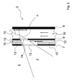
- Fig. 2 shows a vertical sectional view of the door 2.
- the door 2 has a layer structure and comprises an inner wall 7, an outer wall 8 and a partition wall 9 arranged between the inner wall 7 and the outer wall 8.
- the partition wall 9 is only optional, i. e. the present invention can also be implemented without any partition wall 9.
- the door 2 further comprises a camera 10, which in more general terms constitutes an image recording device.
- the camera 10 is mounted between the partition wall 9 and the outer wall 8. As can be seen from Fig. 2 , the camera 10 is mounted to the outer wall 8.
- the outer wall 8 constitutes a heat sink to which the camera 10 and/or an optional cooling element 11 is/are thermally coupled. If a cooling element 11 is used, the camera 10 may be thermally coupled to the cooling element which in turn is thermally coupled to the heat sink.
- the heat sink in the present case constitutes a front cover of the door.
- the front cover is exposed to environmental temperatures of the baking oven 1, which in general are far below the temperatures prevailing within the muffle 2 and within the door 2 during operation of the baking oven 1. Due to the comparatively low temperatures of the heat sink, i. e. front cover, the camera 10 can be efficiently cooled without any further cooling devices.
- the heat sink is formed as a flat sheet-like thermal conductor, which may be made from metal, metal alloys, ceramics, plastics or mixtures thereof. Any other material with good heat conducting and heat emission properties can be used as well.
- the heat sink is made from aluminum which has comparatively good heat conducting properties.
- the heat sink, thermal conductor, outer cover and outer wall are all the same.
- the aluminum heat sink has comparatively good heat conducting and emission properties, heat can be efficiently removed from the camera 10 and released to the surrounding environment, i. e. the camera 10 can be efficiently protected against overtemperatures. Due to the advantageous thermal properties of the aluminum heat sink, temperatures prevailing at the outer side of the door 2 can be kept low reducing the danger of burns.
- the outer wall i. e. the outer cover, in the present case is made from aluminum
- the outer wall is not transparent to a user of the baking oven 1.
- the camera 10 is arranged and adapted to pick up images of the interior of the muffle 5, such that images of an item, such as foodstuff, arranged within the muffle 5 can be presented to the user.
- Sections of the door 2 towards the muffle interior have to be sufficiently transparent and adequately sized so that the camera 10 can pick up images of relevant sections of the muffle interior.
- the inner wall 7 and the partition wall 9 can be provided with image recording windows sized and positioned to obtain a satisfactory field of view F at least with respect to relevant areas or sections within the muffle 5.
- the inner wall is made from glass which is transparent anyway.
- an insulation material 12 is applied for reducing heat transfer and heat loss through the door 2.
- the insulation material 12 has a cut-out sufficiently large so as not to impair the field of view F of the camera 10. Via the cut-out in the insulation material 12 a first image recording window 13 of the inner wall 7 is defined.
- a second image recording window 14 is provided in the partition wall 9.
- the size, location and orientation of the second image recording window 14 is adapted and adjusted to the first image recording window 13 so that an optimal field of view F is obtained.
- the partition wall 9 may be made from glass or other materials, wherein at least the section of the partition wall 9 containing or constituting the second image recording window 14 is made from glass.
- the insulation material 12 is cut out according to the image recording windows. Respective recesses in the insulation material 12 are such that an optimal field of view F can be realized.
- An additional measure to reduce the temperatures within the door 2, i. e. to reduce the thermal load of the camera 10, is to provide cooling channels within the door 2.
- the cooling channels are adapted to guide through a cooling medium.
- a first cooling channel 15 is provided within the insulation material 12, such that a flow of cooling medium can be directed to the first 13 and second image recording window 14.
- a flow of cooling medium is indicated by vertical arrows.
- the first cooling channel 15 is provided as a type of cut-out channel in the insulation material 12.
- the first cooling channel 15 is in particular designed to cool, i. e. to lower the temperature in the space between the first 13 and second image recording window 14. In this way, heat radiation impinging on the camera 10 can be reduced, which in turn reduces the thermal load of the camera 10 and improves image quality.
- the space between the outer wall 8 and the partition wall 9 can be used as a second cooling channel 16.
- a cooling medium such as a gaseous cooling medium, in particular air
- the camera 10 and/or the cooling element 11 can be directly cooled, i. e. directly impinged with cooling medium.
- the camera 10 is shielded from high temperatures prevailing in the muffle 5 by the inner wall 7 and the partition wall 9. Insulation material 12 and circulation of a cooling medium further contribute to reduce temperature load of the camera 10. The insulation material 12 also reduces heat loss through the door, which is a relevant aspect for low energy baking ovens.
- An additional possibility for reducing thermal load of the camera 10 and heat loss through the door 2 is to provide at least the inner wall 7, and/or the partition wall 9 with an infra-red reflecting coating.
- heat radiation through the door 2, i. e. heat loss through the door and thermal load of the camera 10, can be further reduced.
- the infra-red reflecting coating is applied to the side of the inner wall 7 and/or partition wall 9 facing the muffle 5.
- a mat paint On a side of the inner wall 7 and the partition wall 9 oriented away from the muffle5, i. e. facing the camera 10, there may be applied a mat paint. Such a mat paint may be useful in reducing reflections and other optical interferences and disturbances impairing image quality of the camera 10.
- the cooling medium in particular air, can be actively guided through the first and second cooling channel 15 and 16.
- Images recorded by the camera 10 can be presented to a user of the baking oven 1 on a display attached, preferably removably attached, to the baking oven 1.
- a display may be a conventional display device, including optical displays and projection displays and the like fixedly installed at the oven 1.
- images recorded by the camera 10 can be displayed on mobile imaging devices.
- Such a mobile imaging device may be any suitable mobile display device able to communicate with the baking oven 1, i. e. to receive and display images recorded by the camera 10.
- display devices of mobile phones and mobile computers can be used to display images recorded by the camera 10. In the latter cases, information of the camera 10, in particular images of the interior of the muffle 5 can be viewed from remote locations.
- the proposed door is effective in reducing temperature load to a camera mounted within the door.
- the camera can be efficiently protected from thermal impacts, leading to improved image quality, display quality and lifetime of respective imaging devices.
Abstract
Description
- The invention is directed to a baking oven door and to a baking oven comprising such a baking oven door.
- Today, baking ovens, such as household baking ovens, are known which have insulated, non-transparent doors. Such a design may be advantageous for reducing energy consumption and for reducing the temperatures on the outer, user exposed faces of the door.
- As users in general want to observe the baking process within the muffle of the baking oven, optical systems and even camera systems have been proposed in order to visualize the baking chamber, i. e. muffle, at least partially on a display area. Here, reference is made to
DE 79 34 764 U1 ,DE 43 33 443 A1 ,DE 201 03 517 U1 ,DE 20 2008 000 135 U1 andDE 10 2008 043 722 A1 . However, there is still room for further improving such configurations, in particular with respect to display quality. - Starting therefrom it is an object of the invention to provide a baking oven door and a respective baking oven with an improved visualization system adapted to visualize at least parts of the baking chamber, i. e. muffle, to a user.
- This object is solved by the independent claims. Advantageous developments of the invention result from respective dependent claims.
- According to
independent claim 1, a baking oven door is provided which is adapted to be attached to a household or industrial type baking oven. It goes without saying, that baking oven doors are adapted and designed for closing an opening of a muffle, i. e. baking chamber, of the baking oven, in particular during normal operation. The baking oven door can be hingedly and/or slidably attached to the baking oven. - In the following, the term "door" will be used as a short from for the term "baking oven door".
- The door comprises an outer and an inner wall. When mounted to the baking oven and in the closed state of the door, the inner wall faces the muffle of the baking oven, and the outer wall faces away from the muffle, i. e. is exposed to the surroundings and visible by a user.
- The door further comprises at least one image recording device, such as a camera. The at least one image recording device is mounted in between, i. e. in an intermediate space between, the outer and inner wall of the door.
- The at least one image recording device is arranged and adapted to pick up images of the muffle interior. The field of view of the at least one image recording device may be selected or selectable or adjustable, such that at least images of objects placed in standard positions within the muffle can be recorded. It is of advantage, if the image recording device is positioned and adapted such that baking processes of objects within the muffle, i. e. baking chamber, can be adequately tracked by a user.
- In developments, the at least one image recording device, for example having a fixed field of view, can be fixedly attached to the door. In a more elaborate development, actuators coupled to an image recording device and adapted to move and/or rotate a respective image recording device in at least one direction can be provided. Further, it is possible to provide further actuators for adjusting the zoom and/or field of view of the image recording device. By providing actuators and/or further actuators, a user of the baking oven may be allowed to adjust or select the area within the muffle to be recorded by the image recording device. A user interface comprising control elements for controlling the actuators and/or further actuators may be provided as required. In the alternative or in addition, the actuators and/or further actuators may be controlled in an automated manner. In particular, image recording device settings appropriate for a respective user selected baking program can be set automatically in order to provide images of baking program relevant areas of the muffle.
- With the proposed baking oven door, at least a part of the outer side of the outer wall comprises, or even constitutes, a heat sink which is thermally coupled to, i. e. in direct thermal contact with, the image recording device. The outer side of the outer wall shall mean the side facing away from the muffle in the closed state, i. e. the side of the door directly exposed to the environment.
- The heat sink preferably has high thermal conductivity. The heat sink may be an integrated part of the outer wall, and in particular may constitute the outer wall. It is also possible that the heat sink is attached to the outer wall, preferably making up or being part of an outside cover of the door.
- With the proposed configuration, the image recording device can be cooled efficiently via the heat sink. Efficient cooling is, inter alia, advantageous for adequate image quality, and favorable for image recording device lifetimes.
- In a further development, the heat sink is a flat, sheet-like thermal conductor, preferably at least partially constituting an outer cover of the door. Comparatively high cooling efficiency can be obtained if the heat sink covers the whole outer side of the door, i. e. the whole outer side of the outer wall. A further advantage of such a design is that heat loss through the door can be reduced, and, as a yet further advantage, the outer surface of the door can be cleaned comparatively easy.
- In a further development, the outer wall and/or outer cover, in particular the thermal conductor, are/is opaque to a user of the baking oven appliance. In this case, incidence of light from the outside into the muffle can be prevented, which in turn may contribute to improved image quality. As opaque, i. e. non-transparent, materials generally also block heat or heat radiation, the temperature at the outer side can be kept low and heat loss through the door can be reduced, i. e. energy efficiency of the baking oven can be improved.
- In a yet further development, the thermal conductor is made from metal, metal alloys, ceramic and/or plastic. Also composites of the aforementioned materials may be used. The thermal conductor can also or in addition comprise metal, metal alloy, ceramic and/or plastic particles or fibres embedded in a matrix. In particular, these type of materials show good, or even high heat conductivity and heat emissivity, which is advantageous for effectively cooling the image recording device.
- In another development, the inner wall of the door comprises an image recording window, wherein the inner wall is preferably made from glass at least in the region of the image recording window. In particular, the whole inner wall can be made from glass, i. e. the inner wall can comprise a pane of glass. However, it is also possible that only the image recording window or the region of the image recording window is made from glass, whereas the remainder of the inner wall is made from a material other than glass, such for example a material with low thermal conductivity and/or high thermal reflectivity. The image recording window shall be sized and positioned such that the resulting image recording field of view of the image recording device is sufficiently large, to allow imaging of at least the relevant regions of the muffle, such as for example the muffle center. The relevant region may comprise the section of the muffle interior in which items to be baked are positioned in at least most instances. In particular, it is desirable that the image recording field of view is such or can be adapted such that images of items, such as foodstuff and the like, can be recorded for all conventional and usual operating conditions. Imaging of the whole muffle interior may require more than one image recording device and/or may require adaptation of the image recording field of view.
- In a preferred development, the door further comprises at least one partition wall arranged between the outer and inner wall. Preferably, the image recording device is mounted in between, i. e. in a space between, the partition wall and the outer wall and/or in a space between adjacent partition walls. Using a partition wall can greatly reduce heat load of the image recording device.
- The partition wall or partition walls arranged between the image recording device and the inner wall comprises or comprise, respectively, a further image recording window. The further image recording window is preferably sized, positioned and aligned with the image recording window to obtain an optimal field of view. In other words, the further image recording window shall be designed, positioned and sized such that the field of view allowed by the image recording window is not restricted in size by the further image recording window.
- As the image recording window and the at least one further image recording window are arranged in series, the further image recording window may have smaller dimensions than the image recording window of the inner wall. Also, in adequately sizing and positioning and aligning the image recording window and the further image recording window or windows, heat loss through the door can be kept at a minimum.
- The at least one partition wall is preferably made from glass at least in the region of the further image recording window. Here, reference is also made to respective configuration of the inner wall and respective image recording window. In more detail, outside the further image recording window, the partition wall may be made from a material different from glass, preferably a material with low thermal conductivity and preferably high thermal reflectivity. At least in the region of the further image recording window shall in particular include the case that the partition wall as a whole is made from glass.
- In another development, the door comprises at least one channel, preferably running in vertical direction in normal use of the baking oven door. The channel is designed for guiding through a cooling medium, preferably a gaseous cooling medium. With such a channel, which constitutes a kind of cooling channel, the door as such and/or even the image recording device can be directly cooled.
- In embodiments, the channel can be designed as a passive and/or active cooling channel. The term passive cooling channel shall mean that a stream of cooling medium through the channel is established by thermal processes, in particular thermal convection. In this case, vertical channels may be most efficient. The term active cooling channel shall mean that the cooling medium is forced through the channel, for example by a fan, ventilator or blower, which, subject to the design and size of the channel, allow higher flow rates and therefore higher cooling efficiency.
- In a preferred development, at least one channel is arranged at least one of between the inner wall and an adjacent partition wall, between two adjacent partition walls, and the outer wall and an adjacent partition wall. In all cases, the average temperature prevailing in the inner spaces of the door can be reduced, which in turn reduces the temperature load of the image recording device. Further, the temperature at the outer side of the outer wall, i. e. the heat sink, can be reduced. Low temperatures at the outer side are desirable for preventing burns when touching the outer side of the door.
- Preferably, at least one channel is provided in an intermediate space between the inner wall and an adjacent partition wall, two adjacent partition walls, and the outer wall and an adjacent outer wall, in which intermediate space the image recording device is positioned. Here, direct cooling of the image recording device is possible.
- A comparatively low temperature load of the image recording device can be obtained if it is arranged in the outermost space next to the outer wall.
- In a further preferred embodiment, the image recording device is coupled to a cooling element which is arranged within the door, and which is thermally coupled, preferably in direct thermal contact, to the heat sink. By using such a cooling element, heat can be efficiently removed from the image recording device and transferred to the heat sink. The cooling element may be made from metal, in particular light metal, such as aluminum, or a metal alloy.
- In a development, at least one channel for guiding through a cooling medium is arranged and designed such that a cooling medium guided or passing through the channel directly impinges the image recording device and/or the cooling element. In this case, the image recording device can be cooled efficiently.
- In a yet further preferred embodiment, an insulation material is provided at least one of in a space between the inner wall and the outer wall, in a space between the inner wall and an adjacent partition wall, in a space between adjacent partition walls, and in a space between the outer wall and an adjacent partition wall.
- In order not to impair the field of view of the image recording device, the insulation material has recesses adapted to the size of the image recording window and/or further image recording window.
- By using an insulation material, which may be of silicon carbide type or any other suitable type, in particular a porous or granular type material, the image recording device can be shielded from high temperature loads, and the temperature at the outer side of the door can be kept low. Further, the energy loss through the door can be greatly reduced, which is desirable for high energy efficiency type baking ovens.
- At least one channel may pass through, i. e. may be integrated in, the insulation material. The channel is preferably located on a side of the insulation material facing towards the outer wall. In this way, advantageous insulation properties, in particular towards the image recording device, as well as good cooling and energy efficiency can be obtained.
- In a further development, at least the inner wall, and preferably at least one of the at least one partition wall arranged between the image recording device and the inner wall, are coated with an infra-red reflecting material. The infra-red reflecting material is applied on a side facing the muffle in normal use of the door, at least in the region of the image recording window and/or further image recording window. Using such a coating at least in the region of the image recording window and/or further image recording window can lower the temperature load of the image recording device and may reduce heat loss through the door.
- In a further development, at least one of the inner wall, outer wall, and at least one partition wall, is coated with a non-reflecting optic material. The non-reflecting optic material is applied on a side facing towards the outer side of the door, at least in the region of the image recording window and/or further image recording window. Such a nonreflective coating, which may be a black matt paint, may prevent reflections or other optical effects negatively affecting image quality.
- According to
independent claim 15, a baking oven is provided, in particular a baking oven of household or industrial appliance, which comprises at least one muffle and at least one corresponding door as described above, in particular according to any of the described embodiments and developments. - The at least one door is mounted to the baking oven and adapted for closing the at least one muffle during normal operation of the baking oven. The at least one door can for example be hingedly and/or slidably mounted or attached to the baking oven, in particular a frame of the baking oven. As to advantages and advantageous effects of the baking oven, reference is made to the description above.
- In a development of the baking oven, the baking oven may comprise at least one display device adapted to display and/or project images recorded by the image recording device on a display area.
- At least one of the at least one display devices can be mounted at and/or integrated in a front cover of the baking oven, in particular the front wall.
- It is also possible, that images recorded by the image recording device are transmitted, for example by wireless communication, to a mobile display device. Such a mobile display device may be specifically designed for the respective baking oven. However, any suitable mobile display device can be used, in particular portable type screens, displays or screens of mobile phones or mobile computers and the like. Using mobile displays as set out beforehand has the advantage that a user can check the status of items placed within the muffle from nearly any remote location. The baking oven may comprise special fixtures and interfaces for removably fixing and connecting mobile display devices to the baking oven.
- In a preferred development of the baking oven, the image recording device is mounted in an upper part of the door. With such a mounting position favorable fields of view for imaging relevant areas of the muffle of the baking oven can be obtained.
- Exemplary embodiments of the invention will now be described in connection with the annexed figures, in which:
- Fig. 1
- shows a schematic perspective view of a baking oven; and
- Fig. 2
- shows a vertical sectional view of a baking oven door.
- In the figures, like elements are designated by like reference signs.
-
Fig. 1 shows a schematic perspective view of abaking oven 1 comprising adoor 2. Thedoor 2 is hingedly attached to aframe 3 of thebaking oven 1 and is designed and adapted to close at least anopening 4 of a baking camber, i. e. amuffle 5, of thebaking oven 1. - In the present case, the
door 2 is sized such that in the closed state, it covers or extends over nearly the wholefront face 6 of thebaking oven 1. Such configurations are often requested or preferred by customers and users, mainly for design and esthetic reasons. However, a door configured to cover the whole front face may be effective in reducing heat loss through thedoor 2. -
Fig. 2 shows a vertical sectional view of thedoor 2. Thedoor 2 has a layer structure and comprises aninner wall 7, anouter wall 8 and apartition wall 9 arranged between theinner wall 7 and theouter wall 8. Note that thepartition wall 9 is only optional, i. e. the present invention can also be implemented without anypartition wall 9. - The
door 2 further comprises acamera 10, which in more general terms constitutes an image recording device. Thecamera 10 is mounted between thepartition wall 9 and theouter wall 8. As can be seen fromFig. 2 , thecamera 10 is mounted to theouter wall 8. - In accordance with the present invention, the
outer wall 8 constitutes a heat sink to which thecamera 10 and/or an optional cooling element 11 is/are thermally coupled. If a cooling element 11 is used, thecamera 10 may be thermally coupled to the cooling element which in turn is thermally coupled to the heat sink. - The heat sink in the present case constitutes a front cover of the door. The front cover is exposed to environmental temperatures of the
baking oven 1, which in general are far below the temperatures prevailing within themuffle 2 and within thedoor 2 during operation of thebaking oven 1. Due to the comparatively low temperatures of the heat sink, i. e. front cover, thecamera 10 can be efficiently cooled without any further cooling devices. - The heat sink is formed as a flat sheet-like thermal conductor, which may be made from metal, metal alloys, ceramics, plastics or mixtures thereof. Any other material with good heat conducting and heat emission properties can be used as well. In the present case the heat sink is made from aluminum which has comparatively good heat conducting properties. In the present case, the heat sink, thermal conductor, outer cover and outer wall are all the same.
- As the aluminum heat sink has comparatively good heat conducting and emission properties, heat can be efficiently removed from the
camera 10 and released to the surrounding environment, i. e. thecamera 10 can be efficiently protected against overtemperatures. Due to the advantageous thermal properties of the aluminum heat sink, temperatures prevailing at the outer side of thedoor 2 can be kept low reducing the danger of burns. - As the outer wall, i. e. the outer cover, in the present case is made from aluminum, the outer wall is not transparent to a user of the
baking oven 1. As a consequence, items placed within themuffle 5 can not be directly observed by the user's eye. However, thecamera 10 is arranged and adapted to pick up images of the interior of themuffle 5, such that images of an item, such as foodstuff, arranged within themuffle 5 can be presented to the user. - Sections of the
door 2 towards the muffle interior have to be sufficiently transparent and adequately sized so that thecamera 10 can pick up images of relevant sections of the muffle interior. Here, theinner wall 7 and thepartition wall 9 can be provided with image recording windows sized and positioned to obtain a satisfactory field of view F at least with respect to relevant areas or sections within themuffle 5. In the configuration ofFig. 2 , the inner wall is made from glass which is transparent anyway. - In the space between the
partition wall 9 and theinner wall 7 there is arranged aninsulation material 12. The insulation material is applied for reducing heat transfer and heat loss through thedoor 2. - In order to obtain suitable field of view angles □, the
insulation material 12 has a cut-out sufficiently large so as not to impair the field of view F of thecamera 10. Via the cut-out in the insulation material 12 a firstimage recording window 13 of theinner wall 7 is defined. - Further, a second
image recording window 14 is provided in thepartition wall 9. The size, location and orientation of the secondimage recording window 14 is adapted and adjusted to the firstimage recording window 13 so that an optimal field of view F is obtained. Thepartition wall 9 may be made from glass or other materials, wherein at least the section of thepartition wall 9 containing or constituting the secondimage recording window 14 is made from glass. - The
insulation material 12 is cut out according to the image recording windows. Respective recesses in theinsulation material 12 are such that an optimal field of view F can be realized. - An additional measure to reduce the temperatures within the
door 2, i. e. to reduce the thermal load of thecamera 10, is to provide cooling channels within thedoor 2. The cooling channels are adapted to guide through a cooling medium. - In the configuration shown in
Fig. 2 , afirst cooling channel 15 is provided within theinsulation material 12, such that a flow of cooling medium can be directed to the first 13 and secondimage recording window 14. InFig. 2 , a flow of cooling medium is indicated by vertical arrows. - The
first cooling channel 15 is provided as a type of cut-out channel in theinsulation material 12. Thefirst cooling channel 15 is in particular designed to cool, i. e. to lower the temperature in the space between the first 13 and secondimage recording window 14. In this way, heat radiation impinging on thecamera 10 can be reduced, which in turn reduces the thermal load of thecamera 10 and improves image quality. - As an additional way to cool the
camera 10, the space between theouter wall 8 and thepartition wall 9 can be used as asecond cooling channel 16. By guiding through a cooling medium, such as a gaseous cooling medium, in particular air, through thesecond cooling channel 16, thecamera 10 and/or the cooling element 11 can be directly cooled, i. e. directly impinged with cooling medium. - So far, the
camera 10 is shielded from high temperatures prevailing in themuffle 5 by theinner wall 7 and thepartition wall 9.Insulation material 12 and circulation of a cooling medium further contribute to reduce temperature load of thecamera 10. Theinsulation material 12 also reduces heat loss through the door, which is a relevant aspect for low energy baking ovens. - An additional possibility for reducing thermal load of the
camera 10 and heat loss through thedoor 2 is to provide at least theinner wall 7, and/or thepartition wall 9 with an infra-red reflecting coating. In this way, heat radiation through thedoor 2, i. e. heat loss through the door and thermal load of thecamera 10, can be further reduced. Preferably, the infra-red reflecting coating is applied to the side of theinner wall 7 and/orpartition wall 9 facing themuffle 5. - On a side of the
inner wall 7 and thepartition wall 9 oriented away from the muffle5, i. e. facing thecamera 10, there may be applied a mat paint. Such a mat paint may be useful in reducing reflections and other optical interferences and disturbances impairing image quality of thecamera 10. - The cooling medium, in particular air, can be actively guided through the first and
second cooling channel - Images recorded by the
camera 10 can be presented to a user of thebaking oven 1 on a display attached, preferably removably attached, to thebaking oven 1. Such a display may be a conventional display device, including optical displays and projection displays and the like fixedly installed at theoven 1. Further, images recorded by thecamera 10 can be displayed on mobile imaging devices. Such a mobile imaging device may be any suitable mobile display device able to communicate with the bakingoven 1, i. e. to receive and display images recorded by thecamera 10. In particular, display devices of mobile phones and mobile computers can be used to display images recorded by thecamera 10. In the latter cases, information of thecamera 10, in particular images of the interior of themuffle 5 can be viewed from remote locations. - As can be seen, the proposed door is effective in reducing temperature load to a camera mounted within the door. In particular, the camera can be efficiently protected from thermal impacts, leading to improved image quality, display quality and lifetime of respective imaging devices.
- Reference signs
- 1
- baking oven
- 2
- door
- 3
- frame
- 4
- opening
- 5
- muffle
- 6
- front face
- 7
- inner wall
- 8
- outer wall
- 9
- partition wall
- 10
- camera
- 11
- cooling element
- 12
- insulation material
- 13
- first image recording window
- 14
- second image recording window
- 15
- first cooling channel
- 16
- second cooling channel
- F
- field of view
- □
- field of view angle
Claims (17)
- Baking oven door (2) adapted to be attached to a household or industrial type baking oven (1) and being adapted to close an opening (4) to a muffle (5) of the baking oven (1), the baking oven door (2) comprising an outer (8) and an inner wall (7) and at least one image recording device (10), wherein the at least one image recording device (10) is mounted inside the door (2) in between the outer (8) and inner wall (7) and is arranged and adapted to pick up images of the muffle (5) interior, and wherein at least a part of the outer side of the outer wall (8) comprises a heat sink which is thermally coupled to the image recording device (10).
- Baking oven door (2) according to claim 1, wherein the heat sink is a flat, sheet-like thermal conductor (8), preferably at least partially constituting an outer cover of the baking oven door (2).
- Baking oven door (2) according to at least one of the preceding claims, wherein the outer wall (8) and/or outer cover, in particular the thermal conductor, are/is opaque to a user of the baking oven (1).
- Baking oven door (2) according to claim 2 or 3,
wherein the thermal conductor (8) is made from metal,
a metal alloy, ceramic and/or plastic, and/or the thermal conductor (8) comprises metal, metal alloy, ceramic and/or plastic particles and/or fibres embedded in a matrix. - Baking oven door (2) according to at least one of the preceding claims, wherein the inner wall (7) of the door (2) comprises an image recording window (13), wherein the inner wall (7) is preferably made from glass at least in the region of the image recording window (13).
- Baking oven door (2) according to at least one of the preceding claims, further comprising at least one partition wall (9) arranged between the outer (8) and inner wall (7), wherein the image recording device (10) is preferably mounted in between the partition wall (9) and the outer wall (8), and the partition wall/walls (9) between the image recording device (10) and the inner wall (7) comprises/comprise a further image recording window (14), wherein the at least one partition wall (9) is preferably made from glass at least in the region of the further image recording window (14).
- Baking oven door (2) according to at least one of the preceding claims, comprising at least one channel (15, 16), preferably running in vertical direction in normal use of the baking oven door (2), the channel (15, 16) being designed for guiding through a cooling medium, preferably a gaseous cooling medium.
- Baking oven door (2) according to claim 7, wherein at least one channel (15, 16) is arranged at least one of between the inner wall (7) and an adjacent partition wall (9), between two adjacent partition walls (9), and the outer wall (8) and an adjacent partition wall (9).
- Baking oven door (2) according to at least one of the preceding claims, wherein the image recording device (10) is coupled to a cooling element (11) which is arranged within the baking oven door (2) and which is thermally coupled, preferably in direct thermal contact, to the heat sink (8).
- Baking oven door (2) according to at least one of claims 7 to 9, wherein at least one of the at least one channel (16) is arranged and designed such that a cooling medium passing through the channel (16) impinges the image recording device (10) and/or the cooling element (11).
- Baking oven door (2) according to at least one of the preceding claims, wherein an insulation material (12) is provided at least one of in a space between the inner wall (7) and the outer wall (8), in a space between the inner wall (7) and an adjacent partition wall (9), in a space between adjacent partition walls (9) and in a space between the outer wall (8) and an adjacent partition wall (9), wherein the insulation material (12) has recesses adapted to the size of the image recording window (13) and/or further image recording window (14).
- Baking oven door (2) according to at least one of claims 7 to 11, wherein at least one channel (15) passes through the insulation material (12), preferably on a side of the insulation material (12) facing towards the outer wall (8).
- Baking oven door (2) according to at least one of the preceding claims, wherein at least the inner wall (7), and preferably at least one of the at least one partition wall (9) arranged between the image recording device (10) and the inner wall (7), are coated with an infra-red reflecting material on a side facing the muffle (5) in normal use of the baking oven door (2), at least in the region of the image recording window (13) and/or further image recording window (14).
- Baking oven door (2) according to at least one of the preceding claims, wherein at least one of the inner wall (7), outer wall (8) and at least one partition wall (9), is coated with a non-reflecting optic material on a side facing towards the outer side of the baking oven door (2), at least in the region of the image recording window (13) and/or further image recording window (14).
- Baking oven (1), in particular household baking oven, comprising at least one muffle (5) and at least one baking oven door (2) according to at least one of claims 1 to 14, the at least one baking oven door (2) being mounted to the baking oven (1) and adapted for closing the at least one muffle (5) during normal operation of the baking oven (1).
- Baking oven (1) according to claim 15, further comprising at least one display device adapted to display and/or project images recorded by the image recording device (10) on a display area, wherein at least one of the at least one display devices is mounted, in particular integrated, in a front cover of the baking oven, in particular in the front wall (8), or is a mobile type display device.
- Baking oven (1) according to at least one of claims 15 and 16, wherein the image recording device (10) is mounted in an upper part of the baking oven door (2).
Priority Applications (5)
| Application Number | Priority Date | Filing Date | Title |
|---|---|---|---|
| EP11003512.8A EP2520169B1 (en) | 2011-04-29 | 2011-04-29 | Baking oven door and baking oven |
| AU2012247625A AU2012247625B2 (en) | 2011-04-29 | 2012-04-19 | Baking oven door and baking oven |
| US13/978,413 US9982895B2 (en) | 2011-04-29 | 2012-04-19 | Baking oven door and baking oven |
| CN201280006127.3A CN103501618A (en) | 2011-04-29 | 2012-04-19 | Baking oven door and baking oven |
| PCT/EP2012/057118 WO2012146523A1 (en) | 2011-04-29 | 2012-04-19 | Baking oven door and baking oven |
Applications Claiming Priority (1)
| Application Number | Priority Date | Filing Date | Title |
|---|---|---|---|
| EP11003512.8A EP2520169B1 (en) | 2011-04-29 | 2011-04-29 | Baking oven door and baking oven |
Publications (2)
| Publication Number | Publication Date |
|---|---|
| EP2520169A1 true EP2520169A1 (en) | 2012-11-07 |
| EP2520169B1 EP2520169B1 (en) | 2019-12-04 |
Family
ID=44509942
Family Applications (1)
| Application Number | Title | Priority Date | Filing Date |
|---|---|---|---|
| EP11003512.8A Active EP2520169B1 (en) | 2011-04-29 | 2011-04-29 | Baking oven door and baking oven |
Country Status (5)
| Country | Link |
|---|---|
| US (1) | US9982895B2 (en) |
| EP (1) | EP2520169B1 (en) |
| CN (1) | CN103501618A (en) |
| AU (1) | AU2012247625B2 (en) |
| WO (1) | WO2012146523A1 (en) |
Cited By (15)
| Publication number | Priority date | Publication date | Assignee | Title |
|---|---|---|---|---|
| WO2014086487A1 (en) * | 2012-12-04 | 2014-06-12 | Ingo Stork Genannt Wersborg | Heat treatment device with monitoring system |
| EP2930918A1 (en) * | 2014-04-07 | 2015-10-14 | Indesit Company S.p.A. | Oven comprising a camera |
| WO2016034295A1 (en) * | 2014-09-03 | 2016-03-10 | Electrolux Appliances Aktiebolag | Domestic appliance, in particular cooking oven, with a camera |
| WO2016128372A1 (en) * | 2015-02-10 | 2016-08-18 | Electrolux Appliances Aktiebolag | Oven door and oven comprising an oven door |
| EP3263992A1 (en) * | 2016-06-27 | 2018-01-03 | Electrolux Appliances Aktiebolag | Domestic appliance with optical monitoring device |
| DE102017216855A1 (en) | 2017-09-22 | 2019-03-28 | Convotherm-Elektrogeräte Gmbh | Cooking appliance, in particular commercial cooking appliance |
| EP3477209A1 (en) * | 2017-10-27 | 2019-05-01 | Whirlpool Corporation | Oven having an imaging device |
| DE102018201743A1 (en) | 2018-02-05 | 2019-08-08 | Convotherm-Elektrogeräte Gmbh | Cooking appliance, in particular commercial cooking appliance |
| EP3575692A1 (en) * | 2014-08-18 | 2019-12-04 | Stork genannt Wersborg, Ingo | Heat treatment system |
| EP3586063B1 (en) * | 2017-02-21 | 2021-07-07 | BSH Hausgeräte GmbH | Cooking appliance comprising a receiving area for a removable sensor module |
| US11156367B2 (en) | 2020-01-21 | 2021-10-26 | Haier Us Appliance Solutions, Inc. | Oven appliance with an adjustable camera assembly |
| EP3460336B1 (en) * | 2017-09-22 | 2021-12-01 | WELBILT Deutschland GmbH | Cooking device, in particular commercial cooking device |
| US11408611B2 (en) | 2020-01-21 | 2022-08-09 | Haier Us Appliance Solutions, Inc. | Oven appliance with an adjustable camera assembly |
| US11585538B2 (en) | 2018-04-16 | 2023-02-21 | Lg Electronics Inc. | Cooking appliance |
| EP3586064B1 (en) * | 2017-02-21 | 2023-08-30 | BSH Hausgeräte GmbH | Cooking device comprising a removable sensor module |
Families Citing this family (41)
| Publication number | Priority date | Publication date | Assignee | Title |
|---|---|---|---|---|
| EP3292738B1 (en) | 2015-05-05 | 2020-12-30 | June Life, Inc. | A connected oven |
| US9927129B2 (en) * | 2015-06-01 | 2018-03-27 | June Life, Inc. | Thermal management system and method for a connected oven |
| US9879865B2 (en) | 2015-06-08 | 2018-01-30 | Alto-Shaam, Inc. | Cooking oven |
| US9677774B2 (en) | 2015-06-08 | 2017-06-13 | Alto-Shaam, Inc. | Multi-zone oven with variable cavity sizes |
| US10890336B2 (en) | 2015-06-08 | 2021-01-12 | Alto-Shaam, Inc. | Thermal management system for multizone oven |
| US10337745B2 (en) | 2015-06-08 | 2019-07-02 | Alto-Shaam, Inc. | Convection oven |
| US10088172B2 (en) | 2016-07-29 | 2018-10-02 | Alto-Shaam, Inc. | Oven using structured air |
| US9615007B2 (en) | 2015-06-12 | 2017-04-04 | Haier Us Appliance Solutions, Inc. | Oven camera assembly |
| KR102360056B1 (en) * | 2015-07-03 | 2022-02-09 | 삼성전자주식회사 | Oven |
| KR102362654B1 (en) | 2015-07-03 | 2022-02-15 | 삼성전자주식회사 | Oven |
| USD787041S1 (en) | 2015-09-17 | 2017-05-16 | Whirlpool Corporation | Gas burner |
| US10837651B2 (en) | 2015-09-24 | 2020-11-17 | Whirlpool Corporation | Oven cavity connector for operating power accessory trays for cooking appliance |
| US11777190B2 (en) | 2015-12-29 | 2023-10-03 | Whirlpool Corporation | Appliance including an antenna using a portion of appliance as a ground plane |
| US10989417B2 (en) * | 2016-01-27 | 2021-04-27 | Owens Corning Intellectual Capital, Llc | Thermal appliance |
| US10145568B2 (en) | 2016-06-27 | 2018-12-04 | Whirlpool Corporation | High efficiency high power inner flame burner |
| WO2018044067A1 (en) * | 2016-09-01 | 2018-03-08 | Samsung Electronics Co., Ltd. | Oven |
| CN106580120A (en) * | 2016-12-23 | 2017-04-26 | 宁波方太厨具有限公司 | Oven capable of collecting food images |
| JP6850126B2 (en) * | 2016-12-28 | 2021-03-31 | シャープ株式会社 | Cooker |
| JP6850141B2 (en) * | 2017-02-01 | 2021-03-31 | シャープ株式会社 | Cooker |
| US10551056B2 (en) | 2017-02-23 | 2020-02-04 | Whirlpool Corporation | Burner base |
| US10451290B2 (en) | 2017-03-07 | 2019-10-22 | Whirlpool Corporation | Forced convection steam assembly |
| US10660162B2 (en) | 2017-03-16 | 2020-05-19 | Whirlpool Corporation | Power delivery system for an induction cooktop with multi-output inverters |
| DE102017220884A1 (en) | 2017-11-22 | 2019-05-23 | BSH Hausgeräte GmbH | Cooking appliance with image recording device |
| US11116050B1 (en) | 2018-02-08 | 2021-09-07 | June Life, Inc. | High heat in-situ camera systems and operation methods |
| US10523851B2 (en) * | 2018-02-19 | 2019-12-31 | Haier Us Appliance Solutions, Inc. | Camera assembly for an oven appliance |
| US10440245B1 (en) | 2018-05-02 | 2019-10-08 | Haier Us Appliance Solutions, Inc. | Oven appliance camera assembly including a light shield |
| US10627116B2 (en) | 2018-06-26 | 2020-04-21 | Whirlpool Corporation | Ventilation system for cooking appliance |
| US10619862B2 (en) | 2018-06-28 | 2020-04-14 | Whirlpool Corporation | Frontal cooling towers for a ventilation system of a cooking appliance |
| US10837652B2 (en) | 2018-07-18 | 2020-11-17 | Whirlpool Corporation | Appliance secondary door |
| CN108919721B (en) * | 2018-08-02 | 2020-03-10 | 杭州老板电器股份有限公司 | Cooking apparatus and control method thereof |
| DE102018217324A1 (en) | 2018-10-10 | 2020-04-16 | BSH Hausgeräte GmbH | Cooking device with camera and method for operating a cooking device |
| CN111096681B (en) * | 2018-10-25 | 2022-08-26 | 宁波方太厨具有限公司 | Embedded oven convenient to observe food baking state |
| CN111096682B (en) * | 2018-10-25 | 2022-08-26 | 宁波方太厨具有限公司 | Embedded oven |
| US20200166276A1 (en) * | 2018-11-28 | 2020-05-28 | Whirlpool Corporation | Cooking appliance |
| EP3667173B1 (en) * | 2018-12-12 | 2023-06-07 | Electrolux Appliances Aktiebolag | Food preparation entity |
| US11680712B2 (en) | 2020-03-13 | 2023-06-20 | June Life, Inc. | Method and system for sensor maintenance |
| US11593717B2 (en) | 2020-03-27 | 2023-02-28 | June Life, Inc. | System and method for classification of ambiguous objects |
| US11940153B2 (en) | 2020-12-01 | 2024-03-26 | GMG Products, LLC | Fuel conditioner for grill |
| JP7426963B2 (en) | 2021-05-06 | 2024-02-02 | 日立グローバルライフソリューションズ株式会社 | heating cooker |
| WO2022240956A1 (en) * | 2021-05-11 | 2022-11-17 | Jabil Inc. | An apparatus, system and method of cooling sensitive electronics in a heated environment |
| US20230204222A1 (en) * | 2021-12-29 | 2023-06-29 | Whirlpool Corporation | Glass foam for oven camera insulation |
Citations (6)
| Publication number | Priority date | Publication date | Assignee | Title |
|---|---|---|---|---|
| DE7934764U1 (en) | 1978-12-13 | 1980-03-27 | Franke S.P.A., Peschiera Del Garda, Verona (Italien) | OVEN WITH AN OPTICAL DEVICE FOR VIEWING THE FOOD IN IT |
| FR2693538A1 (en) * | 1992-07-07 | 1994-01-14 | Scholtes Ets Eugen | Device for cooling the door of a domestic cooking oven. |
| DE4333443A1 (en) | 1993-09-30 | 1995-04-06 | Bosch Siemens Hausgeraete | Arrangement for observing and monitoring cooking processes in cookers |
| DE20103517U1 (en) | 2001-02-28 | 2001-05-10 | Rational Ag | Cooking appliance with a functional cooking appliance door |
| DE202008000135U1 (en) | 2007-07-24 | 2008-03-13 | Bauer, Robert | Apparatus for making food or bakery products |
| DE102008043722A1 (en) | 2008-11-13 | 2010-05-20 | BSH Bosch und Siemens Hausgeräte GmbH | Household appliance e.g. baking oven, operating arrangement, has portable remote operating unit for operating household appliances, and holder for holding remote operating unit, where holder is integrated into appliance door |
Family Cites Families (27)
| Publication number | Priority date | Publication date | Assignee | Title |
|---|---|---|---|---|
| US2281608A (en) * | 1938-07-15 | 1942-05-05 | Alfred S Vincent | Viewing device for cooking ranges |
| US3453997A (en) * | 1968-03-04 | 1969-07-08 | Chambers Corp | Oven doors |
| US5433189A (en) * | 1994-02-17 | 1995-07-18 | Maytag Corporation | Oven door heat dissipation system |
| US5441036A (en) * | 1994-08-29 | 1995-08-15 | Whirlpool Corporation | Cool multi-sectioned oven door for a large window oven |
| US5960785A (en) * | 1997-05-28 | 1999-10-05 | American Trim, Llc | Cooking range oven having insulated oven door with viewing system |
| DE19737357C2 (en) * | 1997-08-27 | 2001-07-12 | Bsh Bosch Siemens Hausgeraete | Cooking appliance with a screen designed as a screen plate |
| US6024084A (en) * | 1999-02-22 | 2000-02-15 | Engineered Glass Products, Llc | Double sided heat barrier glass with clear CVD coating and method of making the same |
| US6486473B2 (en) * | 2000-03-02 | 2002-11-26 | Mine Safety Applicances Company | Thermal imaging camera |
| US6892030B2 (en) * | 2002-12-17 | 2005-05-10 | John L. Rife | System and method for effecting temperature control in a camera |
| DE10307217B4 (en) * | 2003-02-20 | 2006-04-13 | Schott Ag | Door with viewing window for microwave ovens |
| KR100526206B1 (en) | 2003-03-21 | 2005-11-08 | 삼성전자주식회사 | Cooking Apparatus |
| CA2526216C (en) * | 2003-05-30 | 2010-07-20 | Ppg Industries Ohio, Inc. | Appliance with coated transparency |
| US7329869B2 (en) * | 2005-09-13 | 2008-02-12 | Autoliv Development Ab | Camera system |
| KR100793794B1 (en) * | 2006-04-20 | 2008-01-11 | 엘지전자 주식회사 | Cooking Device |
| US7762250B2 (en) * | 2007-02-06 | 2010-07-27 | Bsh Home Appliances Corporation | Cooking appliance having a latch plate shield for improved guidance of cooling air and exhaust air |
| US8857422B2 (en) * | 2007-02-06 | 2014-10-14 | Bsh Home Appliances Corporation | Oven door assembly having shield for drawing heat away from an oven door window |
| JP5662154B2 (en) * | 2007-11-15 | 2015-01-28 | エックストラリス・テクノロジーズ・リミテッド | Object approach determination method and AVSD system in active video smoke detection (AVSD) system |
| CN101398197A (en) * | 2008-10-20 | 2009-04-01 | 郭恒勋 | Micro-wave oven without microwave radiation |
| CN101435601B (en) * | 2008-12-12 | 2011-03-23 | 申家群 | Non-radiation microwave oven |
| US8753008B2 (en) * | 2009-06-26 | 2014-06-17 | Fluke Corporation | Protective enclosure for a thermal imaging device of an industrial monitoring system |
| US8610822B2 (en) * | 2010-04-19 | 2013-12-17 | Apple Inc. | Camera alignment and mounting structures |
| JP5566198B2 (en) * | 2010-06-16 | 2014-08-06 | キヤノン株式会社 | Electronics |
| GB2500671B8 (en) * | 2012-03-29 | 2014-07-09 | Ev Offshore Ltd | Camera assembly |
| US9060111B2 (en) * | 2012-09-06 | 2015-06-16 | Apple Inc. | Electronic device with compact camera module |
| US9075288B2 (en) * | 2012-09-06 | 2015-07-07 | Sensormatic Electronics, LLC | Pan, tilt, zoom camera system for cooling electronics |
| EP2740258B1 (en) * | 2012-10-15 | 2016-12-21 | GoPro, Inc. | Heat transfer camera ring |
| EP2929252B1 (en) * | 2012-12-04 | 2018-10-24 | Stork genannt Wersborg, Ingo | Haet treatment device with monitoring system |
-
2011
- 2011-04-29 EP EP11003512.8A patent/EP2520169B1/en active Active
-
2012
- 2012-04-19 WO PCT/EP2012/057118 patent/WO2012146523A1/en active Application Filing
- 2012-04-19 AU AU2012247625A patent/AU2012247625B2/en not_active Ceased
- 2012-04-19 US US13/978,413 patent/US9982895B2/en active Active
- 2012-04-19 CN CN201280006127.3A patent/CN103501618A/en active Pending
Patent Citations (6)
| Publication number | Priority date | Publication date | Assignee | Title |
|---|---|---|---|---|
| DE7934764U1 (en) | 1978-12-13 | 1980-03-27 | Franke S.P.A., Peschiera Del Garda, Verona (Italien) | OVEN WITH AN OPTICAL DEVICE FOR VIEWING THE FOOD IN IT |
| FR2693538A1 (en) * | 1992-07-07 | 1994-01-14 | Scholtes Ets Eugen | Device for cooling the door of a domestic cooking oven. |
| DE4333443A1 (en) | 1993-09-30 | 1995-04-06 | Bosch Siemens Hausgeraete | Arrangement for observing and monitoring cooking processes in cookers |
| DE20103517U1 (en) | 2001-02-28 | 2001-05-10 | Rational Ag | Cooking appliance with a functional cooking appliance door |
| DE202008000135U1 (en) | 2007-07-24 | 2008-03-13 | Bauer, Robert | Apparatus for making food or bakery products |
| DE102008043722A1 (en) | 2008-11-13 | 2010-05-20 | BSH Bosch und Siemens Hausgeräte GmbH | Household appliance e.g. baking oven, operating arrangement, has portable remote operating unit for operating household appliances, and holder for holding remote operating unit, where holder is integrated into appliance door |
Cited By (29)
| Publication number | Priority date | Publication date | Assignee | Title |
|---|---|---|---|---|
| US11013237B2 (en) | 2012-12-04 | 2021-05-25 | Ingo Stork Genannt Wersborg | Heat treatment monitoring system |
| WO2014086487A1 (en) * | 2012-12-04 | 2014-06-12 | Ingo Stork Genannt Wersborg | Heat treatment device with monitoring system |
| EP2930918A1 (en) * | 2014-04-07 | 2015-10-14 | Indesit Company S.p.A. | Oven comprising a camera |
| EP3062500A2 (en) | 2014-04-07 | 2016-08-31 | Indesit Company S.p.A. | Oven comprising a camera |
| EP3062500A3 (en) * | 2014-04-07 | 2016-10-05 | Indesit Company S.p.A. | Oven comprising a camera |
| US10808941B2 (en) | 2014-04-07 | 2020-10-20 | Whirlpool Corporation | Oven comprising a camera |
| US9933165B2 (en) | 2014-04-07 | 2018-04-03 | Whirlpool Emea S.P.A. | Oven comprising a camera |
| EP3575692A1 (en) * | 2014-08-18 | 2019-12-04 | Stork genannt Wersborg, Ingo | Heat treatment system |
| WO2016034295A1 (en) * | 2014-09-03 | 2016-03-10 | Electrolux Appliances Aktiebolag | Domestic appliance, in particular cooking oven, with a camera |
| US20170208652A1 (en) * | 2014-09-03 | 2017-07-20 | Electrolux Appliances Aktiebolag | Domestic Appliance, In Particular Cooking Oven, With A Camera |
| US10674569B2 (en) | 2014-09-03 | 2020-06-02 | Electrolux Appliances Aktiebolag | Domestic appliance, in particular cooking oven, with a camera |
| WO2016128372A1 (en) * | 2015-02-10 | 2016-08-18 | Electrolux Appliances Aktiebolag | Oven door and oven comprising an oven door |
| WO2018001722A1 (en) * | 2016-06-27 | 2018-01-04 | Electrolux Appliances Aktiebolag | Domestic appliance with optical monitoring device |
| EP3263992A1 (en) * | 2016-06-27 | 2018-01-03 | Electrolux Appliances Aktiebolag | Domestic appliance with optical monitoring device |
| US10778876B2 (en) | 2016-06-27 | 2020-09-15 | Electrolux Appliances Aktiebolag | Domestic appliance with optical monitoring device |
| EP3586063B1 (en) * | 2017-02-21 | 2021-07-07 | BSH Hausgeräte GmbH | Cooking appliance comprising a receiving area for a removable sensor module |
| EP3586064B1 (en) * | 2017-02-21 | 2023-08-30 | BSH Hausgeräte GmbH | Cooking device comprising a removable sensor module |
| EP3460336B1 (en) * | 2017-09-22 | 2021-12-01 | WELBILT Deutschland GmbH | Cooking device, in particular commercial cooking device |
| US11391466B2 (en) | 2017-09-22 | 2022-07-19 | Welbilt Deutschland GmbH | Cooking appliance, in particular commercial cooking appliance |
| DE102017216855A1 (en) | 2017-09-22 | 2019-03-28 | Convotherm-Elektrogeräte Gmbh | Cooking appliance, in particular commercial cooking appliance |
| US10591218B2 (en) | 2017-10-27 | 2020-03-17 | Whirlpool Corporation | Oven having an imaging device |
| EP3477209A1 (en) * | 2017-10-27 | 2019-05-01 | Whirlpool Corporation | Oven having an imaging device |
| US11231230B2 (en) | 2017-10-27 | 2022-01-25 | Whirlpool Corporation | Oven having an imaging device |
| US11619451B2 (en) | 2017-10-27 | 2023-04-04 | Whirlpool Corporation | Oven having an imaging device |
| DE102018201743A1 (en) | 2018-02-05 | 2019-08-08 | Convotherm-Elektrogeräte Gmbh | Cooking appliance, in particular commercial cooking appliance |
| US11585538B2 (en) | 2018-04-16 | 2023-02-21 | Lg Electronics Inc. | Cooking appliance |
| EP3557136B1 (en) * | 2018-04-16 | 2023-05-31 | LG Electronics Inc. | Cooking appliance |
| US11156367B2 (en) | 2020-01-21 | 2021-10-26 | Haier Us Appliance Solutions, Inc. | Oven appliance with an adjustable camera assembly |
| US11408611B2 (en) | 2020-01-21 | 2022-08-09 | Haier Us Appliance Solutions, Inc. | Oven appliance with an adjustable camera assembly |
Also Published As
| Publication number | Publication date |
|---|---|
| WO2012146523A1 (en) | 2012-11-01 |
| US9982895B2 (en) | 2018-05-29 |
| AU2012247625B2 (en) | 2016-12-22 |
| AU2012247625A1 (en) | 2013-06-20 |
| CN103501618A (en) | 2014-01-08 |
| US20140048055A1 (en) | 2014-02-20 |
| EP2520169B1 (en) | 2019-12-04 |
Similar Documents
| Publication | Publication Date | Title |
|---|---|---|
| EP2520169B1 (en) | Baking oven door and baking oven | |
| EP3247186B1 (en) | Outdoor display screen and communication device | |
| US7228857B2 (en) | Electric oven with door cooling structure | |
| EP3121573B1 (en) | Oven, in particular baking oven or microwave oven | |
| EP3159610B1 (en) | Oven for cooking food | |
| US20200063978A1 (en) | Cooking device comprising a removable sensor module | |
| CN209593569U (en) | A kind of smart machine with Image Acquisition | |
| EP3660403B1 (en) | Cooking appliance | |
| KR101153923B1 (en) | Outdoor display system | |
| KR100953213B1 (en) | Outdoor display enclosure | |
| US20020046749A1 (en) | Stove for cooking food with a viewing window, and a viewing window for household appliances, such as cooking stoves or ovens | |
| US20200128972A1 (en) | Led lighting system for heated enclosure | |
| US11499722B2 (en) | Household cooking appliance having an oven door with an interior camera | |
| US11231177B2 (en) | Fireplace system, heat exchanger and method | |
| US20220248508A1 (en) | Transparent metal coatings for camera pane in microwave oven | |
| KR101524261B1 (en) | Vehicle comprising outdoor display device | |
| CN218390786U (en) | Visual culinary art device and culinary art system | |
| JP4792698B2 (en) | oven | |
| EP4328491A1 (en) | Cooking appliance | |
| JP2020122885A (en) | Camera housing | |
| US20230139545A1 (en) | Cooking appliance | |
| US20230136254A1 (en) | Cooking appliance | |
| CN215637544U (en) | Air conditioner indoor unit and air conditioner | |
| JP2013142838A (en) | Imaging apparatus | |
| CN215637543U (en) | Air conditioner indoor unit and air conditioner |
Legal Events
| Date | Code | Title | Description |
|---|---|---|---|
| PUAI | Public reference made under article 153(3) epc to a published international application that has entered the european phase |
Free format text: ORIGINAL CODE: 0009012 |
|
| 17P | Request for examination filed |
Effective date: 20110915 |
|
| AK | Designated contracting states |
Kind code of ref document: A1 Designated state(s): AL AT BE BG CH CY CZ DE DK EE ES FI FR GB GR HR HU IE IS IT LI LT LU LV MC MK MT NL NO PL PT RO RS SE SI SK SM TR |
|
| AX | Request for extension of the european patent |
Extension state: BA ME |
|
| STAA | Information on the status of an ep patent application or granted ep patent |
Free format text: STATUS: EXAMINATION IS IN PROGRESS |
|
| 17Q | First examination report despatched |
Effective date: 20161027 |
|
| GRAP | Despatch of communication of intention to grant a patent |
Free format text: ORIGINAL CODE: EPIDOSNIGR1 |
|
| STAA | Information on the status of an ep patent application or granted ep patent |
Free format text: STATUS: GRANT OF PATENT IS INTENDED |
|
| RIC1 | Information provided on ipc code assigned before grant |
Ipc: F24C 15/02 20060101ALI20190521BHEP Ipc: A21B 3/02 20060101AFI20190521BHEP Ipc: F24C 15/00 20060101ALI20190521BHEP Ipc: F24C 7/08 20060101ALI20190521BHEP |
|
| INTG | Intention to grant announced |
Effective date: 20190624 |
|
| GRAS | Grant fee paid |
Free format text: ORIGINAL CODE: EPIDOSNIGR3 |
|
| GRAA | (expected) grant |
Free format text: ORIGINAL CODE: 0009210 |
|
| STAA | Information on the status of an ep patent application or granted ep patent |
Free format text: STATUS: THE PATENT HAS BEEN GRANTED |
|
| RIN1 | Information on inventor provided before grant (corrected) |
Inventor name: RUTHER, FLORIAN |
|
| AK | Designated contracting states |
Kind code of ref document: B1 Designated state(s): AL AT BE BG CH CY CZ DE DK EE ES FI FR GB GR HR HU IE IS IT LI LT LU LV MC MK MT NL NO PL PT RO RS SE SI SK SM TR |
|
| REG | Reference to a national code |
Ref country code: GB Ref legal event code: FG4D |
|
| REG | Reference to a national code |
Ref country code: CH Ref legal event code: EP |
|
| REG | Reference to a national code |
Ref country code: AT Ref legal event code: REF Ref document number: 1208250 Country of ref document: AT Kind code of ref document: T Effective date: 20191215 |
|
| REG | Reference to a national code |
Ref country code: DE Ref legal event code: R096 Ref document number: 602011063742 Country of ref document: DE |
|
| REG | Reference to a national code |
Ref country code: IE Ref legal event code: FG4D |
|
| REG | Reference to a national code |
Ref country code: NL Ref legal event code: MP Effective date: 20191204 |
|
| REG | Reference to a national code |
Ref country code: LT Ref legal event code: MG4D |
|
| PG25 | Lapsed in a contracting state [announced via postgrant information from national office to epo] |
Ref country code: ES Free format text: LAPSE BECAUSE OF FAILURE TO SUBMIT A TRANSLATION OF THE DESCRIPTION OR TO PAY THE FEE WITHIN THE PRESCRIBED TIME-LIMIT Effective date: 20191204 Ref country code: LV Free format text: LAPSE BECAUSE OF FAILURE TO SUBMIT A TRANSLATION OF THE DESCRIPTION OR TO PAY THE FEE WITHIN THE PRESCRIBED TIME-LIMIT Effective date: 20191204 Ref country code: SE Free format text: LAPSE BECAUSE OF FAILURE TO SUBMIT A TRANSLATION OF THE DESCRIPTION OR TO PAY THE FEE WITHIN THE PRESCRIBED TIME-LIMIT Effective date: 20191204 Ref country code: BG Free format text: LAPSE BECAUSE OF FAILURE TO SUBMIT A TRANSLATION OF THE DESCRIPTION OR TO PAY THE FEE WITHIN THE PRESCRIBED TIME-LIMIT Effective date: 20200304 Ref country code: FI Free format text: LAPSE BECAUSE OF FAILURE TO SUBMIT A TRANSLATION OF THE DESCRIPTION OR TO PAY THE FEE WITHIN THE PRESCRIBED TIME-LIMIT Effective date: 20191204 Ref country code: LT Free format text: LAPSE BECAUSE OF FAILURE TO SUBMIT A TRANSLATION OF THE DESCRIPTION OR TO PAY THE FEE WITHIN THE PRESCRIBED TIME-LIMIT Effective date: 20191204 Ref country code: NO Free format text: LAPSE BECAUSE OF FAILURE TO SUBMIT A TRANSLATION OF THE DESCRIPTION OR TO PAY THE FEE WITHIN THE PRESCRIBED TIME-LIMIT Effective date: 20200304 Ref country code: GR Free format text: LAPSE BECAUSE OF FAILURE TO SUBMIT A TRANSLATION OF THE DESCRIPTION OR TO PAY THE FEE WITHIN THE PRESCRIBED TIME-LIMIT Effective date: 20200305 |
|
| PG25 | Lapsed in a contracting state [announced via postgrant information from national office to epo] |
Ref country code: RS Free format text: LAPSE BECAUSE OF FAILURE TO SUBMIT A TRANSLATION OF THE DESCRIPTION OR TO PAY THE FEE WITHIN THE PRESCRIBED TIME-LIMIT Effective date: 20191204 Ref country code: HR Free format text: LAPSE BECAUSE OF FAILURE TO SUBMIT A TRANSLATION OF THE DESCRIPTION OR TO PAY THE FEE WITHIN THE PRESCRIBED TIME-LIMIT Effective date: 20191204 |
|
| PG25 | Lapsed in a contracting state [announced via postgrant information from national office to epo] |
Ref country code: AL Free format text: LAPSE BECAUSE OF FAILURE TO SUBMIT A TRANSLATION OF THE DESCRIPTION OR TO PAY THE FEE WITHIN THE PRESCRIBED TIME-LIMIT Effective date: 20191204 |
|
| PG25 | Lapsed in a contracting state [announced via postgrant information from national office to epo] |
Ref country code: RO Free format text: LAPSE BECAUSE OF FAILURE TO SUBMIT A TRANSLATION OF THE DESCRIPTION OR TO PAY THE FEE WITHIN THE PRESCRIBED TIME-LIMIT Effective date: 20191204 Ref country code: CZ Free format text: LAPSE BECAUSE OF FAILURE TO SUBMIT A TRANSLATION OF THE DESCRIPTION OR TO PAY THE FEE WITHIN THE PRESCRIBED TIME-LIMIT Effective date: 20191204 Ref country code: NL Free format text: LAPSE BECAUSE OF FAILURE TO SUBMIT A TRANSLATION OF THE DESCRIPTION OR TO PAY THE FEE WITHIN THE PRESCRIBED TIME-LIMIT Effective date: 20191204 Ref country code: EE Free format text: LAPSE BECAUSE OF FAILURE TO SUBMIT A TRANSLATION OF THE DESCRIPTION OR TO PAY THE FEE WITHIN THE PRESCRIBED TIME-LIMIT Effective date: 20191204 Ref country code: PT Free format text: LAPSE BECAUSE OF FAILURE TO SUBMIT A TRANSLATION OF THE DESCRIPTION OR TO PAY THE FEE WITHIN THE PRESCRIBED TIME-LIMIT Effective date: 20200429 |
|
| PG25 | Lapsed in a contracting state [announced via postgrant information from national office to epo] |
Ref country code: SK Free format text: LAPSE BECAUSE OF FAILURE TO SUBMIT A TRANSLATION OF THE DESCRIPTION OR TO PAY THE FEE WITHIN THE PRESCRIBED TIME-LIMIT Effective date: 20191204 Ref country code: SM Free format text: LAPSE BECAUSE OF FAILURE TO SUBMIT A TRANSLATION OF THE DESCRIPTION OR TO PAY THE FEE WITHIN THE PRESCRIBED TIME-LIMIT Effective date: 20191204 Ref country code: IS Free format text: LAPSE BECAUSE OF FAILURE TO SUBMIT A TRANSLATION OF THE DESCRIPTION OR TO PAY THE FEE WITHIN THE PRESCRIBED TIME-LIMIT Effective date: 20200404 |
|
| REG | Reference to a national code |
Ref country code: DE Ref legal event code: R097 Ref document number: 602011063742 Country of ref document: DE |
|
| REG | Reference to a national code |
Ref country code: AT Ref legal event code: MK05 Ref document number: 1208250 Country of ref document: AT Kind code of ref document: T Effective date: 20191204 |
|
| PLBE | No opposition filed within time limit |
Free format text: ORIGINAL CODE: 0009261 |
|
| STAA | Information on the status of an ep patent application or granted ep patent |
Free format text: STATUS: NO OPPOSITION FILED WITHIN TIME LIMIT |
|
| PG25 | Lapsed in a contracting state [announced via postgrant information from national office to epo] |
Ref country code: DK Free format text: LAPSE BECAUSE OF FAILURE TO SUBMIT A TRANSLATION OF THE DESCRIPTION OR TO PAY THE FEE WITHIN THE PRESCRIBED TIME-LIMIT Effective date: 20191204 |
|
| 26N | No opposition filed |
Effective date: 20200907 |
|
| PG25 | Lapsed in a contracting state [announced via postgrant information from national office to epo] |
Ref country code: SI Free format text: LAPSE BECAUSE OF FAILURE TO SUBMIT A TRANSLATION OF THE DESCRIPTION OR TO PAY THE FEE WITHIN THE PRESCRIBED TIME-LIMIT Effective date: 20191204 Ref country code: AT Free format text: LAPSE BECAUSE OF FAILURE TO SUBMIT A TRANSLATION OF THE DESCRIPTION OR TO PAY THE FEE WITHIN THE PRESCRIBED TIME-LIMIT Effective date: 20191204 Ref country code: PL Free format text: LAPSE BECAUSE OF FAILURE TO SUBMIT A TRANSLATION OF THE DESCRIPTION OR TO PAY THE FEE WITHIN THE PRESCRIBED TIME-LIMIT Effective date: 20191204 Ref country code: MC Free format text: LAPSE BECAUSE OF FAILURE TO SUBMIT A TRANSLATION OF THE DESCRIPTION OR TO PAY THE FEE WITHIN THE PRESCRIBED TIME-LIMIT Effective date: 20191204 |
|
| REG | Reference to a national code |
Ref country code: CH Ref legal event code: PL |
|
| PG25 | Lapsed in a contracting state [announced via postgrant information from national office to epo] |
Ref country code: CH Free format text: LAPSE BECAUSE OF NON-PAYMENT OF DUE FEES Effective date: 20200430 Ref country code: LU Free format text: LAPSE BECAUSE OF NON-PAYMENT OF DUE FEES Effective date: 20200429 Ref country code: LI Free format text: LAPSE BECAUSE OF NON-PAYMENT OF DUE FEES Effective date: 20200430 |
|
| REG | Reference to a national code |
Ref country code: BE Ref legal event code: MM Effective date: 20200430 |
|
| PG25 | Lapsed in a contracting state [announced via postgrant information from national office to epo] |
Ref country code: BE Free format text: LAPSE BECAUSE OF NON-PAYMENT OF DUE FEES Effective date: 20200430 |
|
| GBPC | Gb: european patent ceased through non-payment of renewal fee |
Effective date: 20200429 |
|
| PG25 | Lapsed in a contracting state [announced via postgrant information from national office to epo] |
Ref country code: IE Free format text: LAPSE BECAUSE OF NON-PAYMENT OF DUE FEES Effective date: 20200429 Ref country code: GB Free format text: LAPSE BECAUSE OF NON-PAYMENT OF DUE FEES Effective date: 20200429 |
|
| PG25 | Lapsed in a contracting state [announced via postgrant information from national office to epo] |
Ref country code: TR Free format text: LAPSE BECAUSE OF FAILURE TO SUBMIT A TRANSLATION OF THE DESCRIPTION OR TO PAY THE FEE WITHIN THE PRESCRIBED TIME-LIMIT Effective date: 20191204 Ref country code: MT Free format text: LAPSE BECAUSE OF FAILURE TO SUBMIT A TRANSLATION OF THE DESCRIPTION OR TO PAY THE FEE WITHIN THE PRESCRIBED TIME-LIMIT Effective date: 20191204 Ref country code: CY Free format text: LAPSE BECAUSE OF FAILURE TO SUBMIT A TRANSLATION OF THE DESCRIPTION OR TO PAY THE FEE WITHIN THE PRESCRIBED TIME-LIMIT Effective date: 20191204 |
|
| PG25 | Lapsed in a contracting state [announced via postgrant information from national office to epo] |
Ref country code: MK Free format text: LAPSE BECAUSE OF FAILURE TO SUBMIT A TRANSLATION OF THE DESCRIPTION OR TO PAY THE FEE WITHIN THE PRESCRIBED TIME-LIMIT Effective date: 20191204 |
|
| PGFP | Annual fee paid to national office [announced via postgrant information from national office to epo] |
Ref country code: IT Payment date: 20230421 Year of fee payment: 13 Ref country code: FR Payment date: 20230421 Year of fee payment: 13 Ref country code: DE Payment date: 20230427 Year of fee payment: 13 |
|
| P01 | Opt-out of the competence of the unified patent court (upc) registered |
Effective date: 20230625 |