EP2520148B1 - Verfahren zur Messung eines Gutstroms mittels Microwellen, Sensoranordnung und Vorrichtung mit einer Sensoranordnung - Google Patents
Verfahren zur Messung eines Gutstroms mittels Microwellen, Sensoranordnung und Vorrichtung mit einer Sensoranordnung Download PDFInfo
- Publication number
- EP2520148B1 EP2520148B1 EP12002983.0A EP12002983A EP2520148B1 EP 2520148 B1 EP2520148 B1 EP 2520148B1 EP 12002983 A EP12002983 A EP 12002983A EP 2520148 B1 EP2520148 B1 EP 2520148B1
- Authority
- EP
- European Patent Office
- Prior art keywords
- flow
- transmitter
- microwaves
- receiver
- microwave
- Prior art date
- Legal status (The legal status is an assumption and is not a legal conclusion. Google has not performed a legal analysis and makes no representation as to the accuracy of the status listed.)
- Active
Links
Images

Classifications
-
- A—HUMAN NECESSITIES
- A01—AGRICULTURE; FORESTRY; ANIMAL HUSBANDRY; HUNTING; TRAPPING; FISHING
- A01C—PLANTING; SOWING; FERTILISING
- A01C7/00—Sowing
- A01C7/08—Broadcast seeders; Seeders depositing seeds in rows
- A01C7/10—Devices for adjusting the seed-box ; Regulation of machines for depositing quantities at intervals
- A01C7/102—Regulating or controlling the seed rate
- A01C7/105—Seed sensors
-
- G—PHYSICS
- G01—MEASURING; TESTING
- G01N—INVESTIGATING OR ANALYSING MATERIALS BY DETERMINING THEIR CHEMICAL OR PHYSICAL PROPERTIES
- G01N22/00—Investigating or analysing materials by the use of microwaves or radio waves, i.e. electromagnetic waves with a wavelength of one millimetre or more
Definitions
- the invention relates to a method for agricultural sowing and spreading machines for measuring a crop flow according to claim 1, and to an agricultural sowing or spreading machine according to claim 2.
- material flows are conveyed.
- the material being conveyed is particles such as grains, granules, shot, coarse-grained powders, etc.
- Examples of applications include the pneumatic or free-fall conveying of grains, granules, powders and shot in, for example, agricultural seed drills and pneumatic fertilizer spreaders or centrifugal spreaders, the food and feed industry, the building materials industry or in production, such as the conveying of plastic granules to injection molding machines.
- each seed coulter is assigned a dosing unit, e.g. for corn, beans, pelleted sugar beet seeds or similar.
- seed drills on the other hand, the seed, e.g. all types of grain, rapeseed, grass seed or similar, is distributed from a container to a distribution system via a dosing unit in proportion to the driving speed. The seed is then distributed either freely, so-called mechanical seeding mechanism, or by means of air flow, so-called pneumatic seeding mechanism, through a large number of from lines to the sowing coulters.
- the seed With pneumatic seed drills the seed is generally blown from below by a dosing unit via a main line in an air stream into spherical segment-shaped distribution heads. In the distribution head the material flow is distributed into sowing lines.
- the sowing line the sowing pipe, conveys the seed to one sowing coulter each, which places the seed in the soil.
- a large number of sowing coulters are used here, e.g. with a sowing coulter spacing of 15 cm this corresponds to 60 sowing coulters with a working width of 9 m.
- the seed is dosed according to a calibration proportional to the driving speed so that a certain distribution in terms of mass or number of seeds per unit area is achieved.
- longitudinal distribution i.e. distribution in the direction of travel
- transverse distribution i.e. distribution across the working width of the machine.
- Problems when using pneumatic seed drills include: detecting a gradual or partial blockage or clogging of the line, measuring the actual throughput, i.e. the mass and/or number of seeds per unit of time, and the distribution accuracy in longitudinal and transverse distribution.
- sensors are known, particularly for sowing machines: optical sensors that work reflectively or transflectively with one or more light detectors, e.g. a phototransistor, mechanical sensors such as a pin in the crop flow with a coupled piezo element for counting impacting particles, structure-borne sound sensors for measuring the structure-borne sound when small particles hit, measuring the pulse energy when hitting a piezo element or an array of piezo elements, radiometric sensors with radiation transmission and scintillation detector, ultrasonic sensors for measuring the energy reflected from the material flow and capacitive sensors as amplitude-determining element in an oscillator circuit such as in the US$4,782,282 described.
- a light detectors e.g. a phototransistor
- mechanical sensors such as a pin in the crop flow with a coupled piezo element for counting impacting particles
- structure-borne sound sensors for measuring the structure-borne sound when small particles hit
- measuring the pulse energy when hitting a piezo element or an array of piezo elements measuring the pulse energy when hitting a
- optical sensors are most commonly used for blockage detection and counting of mostly large seeds, e.g. corn, soybeans, in precision seed drills.
- Counting i.e. throughput recording
- large seeds such as corn and soybeans.
- Counting the seeds using optical sensors is prone to errors, as duplications can occur due to overlapping seeds. Reliable optical counting is technically very complex.
- a capacitive measuring method which propagates electromagnetic energy with a predetermined frequency and amplitude into a measuring chamber.
- the electromagnetic sensor records the signal changes of the electromagnetic energy in the measuring chamber, which are caused by the disturbance of the electromagnetic energy field and the passage of the analyte.
- the source of the electromagnetic energy propagates non-resonant electromagnetic energy in a material-specific manner. frequency and amplitude to be determined into the measuring chamber.
- US6,346,888 B1 further discloses under the generic term specific designs of possible applications of the material sensor and determinations of the flow rate of substances that flow as a continuum using the Doppler technique.
- the frequency-shifted received signal is related to the speed and thus to the flow rate.
- US6,346,888 B1 therefore only and exclusively discloses the use of the resulting Doppler frequency to measure the velocity of the substance flowing as a continuum and the associated flow rate.
- the US 5,644,244 A discloses a method for determining the ratio of solid to liquid substances by means of phase shifting of reference and test microwaves.
- the Doppler radar method is used to measure the parameter "speed" of the material flowing through, whereby a further evaluation of the reflected radiation with regard to the layer thickness is carried out in order to determine the layer thickness of the material flow.
- the object of the present invention is to improve methods and sensor arrangements from the prior art.
- this object is achieved by a method for agricultural sowing and spreading machines for measuring a material flow according to claim 1.
- the object to be sensed moves through the transmitted microwave signal.
- This signal is diffusely partially scattered or reflected by the object to be sensed. Due to Due to the Doppler effect, the frequency of the reflected wave is shifted proportionally to the speed of the object.
- the low-frequency beat signal to be evaluated is created by mixing the transmitted and received signals.
- the material flow rate is calculated from the amplitude of the beat signal. This is possible because the amplitude of the beat signal is proportional to the material flow rate or the size of the particles.
- the speed of the goods can be calculated from the frequency of the beat signal. This is possible because the frequency of the beat signal is proportional to the speed of the goods.
- a further aspect of the invention relates to an agricultural sowing or spreading machine according to claim 2.
- the agricultural sowing or spreading machine with the sensor arrangement for measuring a material flow of particles using microwaves with a microwave transmitter and a microwave receiver is designed in such a way that the transmitter and the receiver are arranged in such a way that the microwaves are sent by the transmitter into a material flow and are reflected from the material flow to the receiver.
- the sensor arrangement consisting of microwave transmitter and microwave receiver continuously sends electromagnetic waves.
- the material to be sensed moves due to the emitted waves.
- the electromagnetic waves emitted by the transmitter are diffusely partially scattered back or reflected by the material to be sensed.
- the superposition creates the beat signal at the receiver, which can then be evaluated according to the method according to the invention.
- the transmitter emits microwaves with a frequency of 0.2 GHz to 600 GHz, especially from 0.3 GHz to 300 GHz.
- the invention is also applicable to frequencies above 300 GHz.
- Transmitters and receivers send and receive electromagnetic waves using antennas. These can therefore have antennas.
- the antennas are advantageously designed as planar or point source antennas with a main lobe of the radiation characteristic that covers the flow of material.
- the material flow can move freely falling, thrown or flowing.
- the senor arrangement has a line for the flow of material.
- the transmitter and receiver can then be installed at an angle to the line so that an antenna continuously sends electromagnetic waves through the line.
- Each line can have a pneumatic conveying system for the flow of goods.
- pneumatic conveying the goods are transported by compressed air. This is generated by compressing the ambient air in a compressor. This allows the speed of the goods being transported to be determined. In addition, transport against gravity is also possible.
- the pipe can be arranged to slope downwards. This allows the seeds to be transported by gravity.
- the line is made of a material that is permeable to the microwave signal.
- This can in particular be any non-metallic material.
- the method and a sensor arrangement according to the invention make it possible to quantitatively detect and count the particles of a moving material flow consisting of particles, so-called particulate material, in a line system with high accuracy.
- the machine can be a seed drill.
- the device is a seed drill and has a seed tube with a sensor arrangement. If several sensor arrangements are provided on several seed tubes, precise monitoring and recording of the longitudinal and transverse distribution is possible.
- a final aspect of the disclosure includes a use of a monostatic continuous wave radar for measuring a moving flow of particles or a liquid, wherein the particles or liquid are quantitatively detected and/or counted.
- the continuous wave radar can be frequency or amplitude modulated.
- the use of a pulsed radar is also possible.
- the inventive concept of the present application has the following advantages:
- the high-resolution measurement enables the throughput to be recorded and particles to be counted.
- a measurement on all the seed tubes of a seed drill enables precise monitoring and recording of the longitudinal and transverse distribution.
- a partial blockage with a reduction in the throughput on individual seed tubes is not only possible when the seed tube is completely full up to the measuring point due to the blockage. It is also possible to detect and monitor the shutdown of the seed flow in individual lines when tramlines are created.
- the measurability of the throughput in individual lines opens up optimization potential through blockage detection at an early stage and the monitoring, control and regulation of the longitudinal and transverse distribution.
- the proposed arrangement is insensitive to contamination. It is also comparatively simple in construction and inexpensive to manufacture.
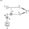
- the microwave signal generated by the oscillator O is sent to the object G via the transmitter. Part of this signal is reflected onto the receiving antenna E. The two signals are superimposed by a mixer M. This produces the Doppler frequency signal fD, which is amplified by an amplifier or filter VE. After processing in an analog-digital converter ADU and a microcontroller MCU, the result is output.
- the Figures 2 and 3 show examples of such a Doppler signal fD.
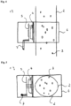
- the sensor arrangement 1 shown is connected to a pipe 2.
- a material flow with individual grains 3 is conveyed in the pipe 2.
- the sensor arrangement with a radar front end 4, which is connected to an electronic circuit 5 on a circuit board, is arranged in a metal housing 6.
- the measurement results of the radar front end 4, which were processed by the electronics 5, are forwarded via a cable 7.
Landscapes
- Life Sciences & Earth Sciences (AREA)
- Soil Sciences (AREA)
- Environmental Sciences (AREA)
- Physics & Mathematics (AREA)
- Electromagnetism (AREA)
- Health & Medical Sciences (AREA)
- Chemical & Material Sciences (AREA)
- Analytical Chemistry (AREA)
- Biochemistry (AREA)
- General Health & Medical Sciences (AREA)
- General Physics & Mathematics (AREA)
- Immunology (AREA)
- Pathology (AREA)
- Measuring Volume Flow (AREA)
- Measurement Of Levels Of Liquids Or Fluent Solid Materials (AREA)
Description
- Die Erfindung betrifft ein Verfahren für landwirtschaftliche Sä- und Streumaschinen zur Messung eines Gutstroms gemäß Anspruch 1, und eine Landwirtschaftiche Sä- oder Streumaschine gemäß Anspruch 2.
- In zahlreichen industriellen Anwendungen werden Gutströme gefördert. Bei dem geförderten Material handelt es sich um Teilchen, wie z.B. Körner, Granulate, Schrote, grobkörnige Pulver etc. Anwendungsbeispiele sind die pneumatische oder frei fallende Förderung von Körnern, Granulaten, Pulver und Schroten in z. B. landwirtschaftlichen Sämaschinen und pneumatischen Düngerstreuern bzw. Schleuderstreuern, der Lebensmittel- und Futtermittelindustrie, der Baustoffindustrie oder in der Produktion, wie beispielsweise die Förderung von Kunststoffgranulat zu Spritzgussmaschinen.
- Ein Anwendungsbereich aus dem Stand der Technik, auf den im Folgenden näher eingegangen werden soll, sind landwirtschaftliche Sämaschinen. Bei Einzelkornsämaschinen ist jedem Säschar eine Dosiereinheit z. B. für Mais, Bohnen, pillierte Zuckerrübensamen oder ähnliches zugeordnet. Bei sogenannten Drillmaschinen hingegen wird das Saatgut, z. B. Getreide aller Art, Rapssamen, Grassamen oder Ähnliches, aus einem Behälter proportional zur Fahrgeschwindigkeit über eine Dosiereinheit einem Verteilsystem zugeteilt. Das Saatgut wird in der Folge entweder frei fallend, sogenannter mechanischer Sämechanismus, oder mittels Luftstrom, sogenannter pneumatischer Sämechanismus, durch eine Vielzahl von Leitungen zu den Säscharen gefördert. Bei pneumatischen Drillmaschinen wird im Allgemeinen das Saatgut von einer Dosiereinheit über eine Hauptleitung im Luftstrom in kugelsegmentförmige Verteilköpfe von unten eingeblasen. Im Verteilkopf wird der Gutstrom in Säleitungen verteilt. Die Säleitung, die sogenannte Saatpfeife, fördert das Saatgut zu jeweils einem Säschar, welches das Saatgut im Boden ablegt. Hierbei wird eine Vielzahl von Säscharen eingesetzt, z. B. bei einem Säscharabstand von 15 cm entsprechend 60 Säschare bei 9 m Arbeitsbreite. Die Dosierung des Saatguts erfolgt entsprechend einer Kalibrierung proportional zur Fahrgeschwindigkeit, so dass eine bestimmte Verteilung bezüglich Masse oder Anzahl der Saatkörner pro Flächeneinheit erreicht wird. Bei der Beurteilung der Verteilung ist die Längs-, d. h. die Verteilung in Fahrtrichtung, von der Querverteilung, d. h. die Verteilung über die Arbeitsbreite der Maschine, zu unterscheiden.
- Ein weiterer Anwendungsbereich sind Streumaschinen ("Schleuderstreuer"). Hierbei wird granuliertes Material meist von einer sich drehenden Scheibe geschleudert und so flächig verteilt.
- Problematisch beim Einsatz pneumatischer Sämaschinen sind: die Erfassung einer allmählichen oder teilweisen Blockade bzw. Verstopfung der Leitung, die Messung des tatsächlichen Durchsatzes, d. h. der Masse und/oder der Anzahl der Körner pro Zeiteinheit, und die Verteilgenauigkeit in Längs- und Querverteilung.
- Aus dem Stand der Technik sind zahlreiche Lösungen bekannt, um einen Gutstrom zu erfassen. Insbesondere bei Sämaschinen sind folgende Sensoren bekannt: optische Sensoren, die reflektiv oder transflektiv mit einem oder mehreren Lichtdetektoren, z. B. einem Phototransistor, wirken, mechanische Sensoren wie einen Stift im Gutstrom mit angekoppeltem Piezoelement zur Zählung auftreffender Partikel, Körperschallsensoren zur Messung des Körperschalls beim Auftreffen von Körperchen, die Messung der Impulsenergie beim Auftreffen auf ein Piezoelement oder eine Array aus Piezoelementen, radiometrische Sensoren mit Strahlungstransmission und Szintillationsdetektor, Ultraschallsensoren zur Messung der vom Gutstrom reflektierten Energie und kapazitive Sensoren als amplitudenbestimmendes Element in einer Oszillatorschaltung wie beispielsweise in der
US 4,782,282 beschrieben. - Auch eine Verwendung von Mikrowellenabsorption durch den Gutstrom, sogenannte TEM Transversal-Elektromagnetische Mode, im Hohlraumresonator wie in
US 4,246,469 beschrieben wurden vorgeschlagen. - Hiervon finden in der aktuellen Praxis am häufigsten optische Sensoren zur Blockadeerkennung und Zählung meist grosser Saatkörner, z. B. Mais, Sojabohnen, in Einzelkornsämaschinen Verwendung.
- Problem bei der Blockadeerkennung ist, dass diese nur auf vollständig oder weitgehend verstopfte Leitungen anspricht. Tritt eine Blockade des Säschares auf, so wird diese erst erkannt, wenn das Rohr bis zur Messstelle mit Material angefüllt ist. Teilblockaden mit verringertem Durchsatz sind schwer zu erkennen.
- Die Zählung, d. h. die Durchsatzerfassung, ist meist nur bei grossen Saatkörnern wie Mais und Sojabohnen möglich. Die Zählung der Körner mittels optischer Sensoren ist fehlerbehaftet, da Dopplungen durch überlappende Körner auftreten können. Eine sichere optische Zählung ist technisch sehr aufwändig.
- Aus
US 6,346,888 B1 ist ein kapazitives Messverfahren bekannt, welches elektromagnetische Energie mit einer vorab bestimmten Frequenz und Amplitude in eine Messkammer ausbreitet. Der elektromagnetische Messwertgeber erfasst dabei die Signalveränderungen der elektromagnetischen Energie in der Messkammer, welche durch die Störung des elektromagnetischen Energiefeldes und der Passage des Analytikums verursacht wird. Die Quelle der elektromagnetischen Energie verbreitet (propagates) hierzu nicht-resonante elektromagnetische Energie in vorab material-spezifisch festzulegender Frequenz und Amplitude in die Messkammer. - Die
US 6,346,888 B1 offenbart des Weiteren unter dem Oberbegriff spezifische Gestaltungen möglicher Anwendungen des Materialsensors und Bestimmungen der Durchflussrate von Substanzen, welche als Kontinuum fließen, unter Nutzung der Doppler Technik. Hierbei wird das frequenzverschobene Empfangssignal mit der Geschwindigkeit und so mit der Durchflussrate in Beziehung gebracht.US 6,346,888 B1 offenbart mithin nur und ausschließlich die Nutzung der entstehenden Dopplerfrequenz zur Geschwindigkeitsmessung der als Kontinuum fließenden Substanz und der damit zusammenhängenden Durchflussrate. - Die
US 5,644,244 A offenbart ein Verfahren zur Bestimmung des Verhältnisses von festen zu flüssigen Substanzen mittels Phasenverschiebung von Referenz- und Test-Mikrowellen. - In der
EP 0 843 959 A1 wird das Doppler-Radarverfahren zur Messung des Parameters "Geschwindigkeit" des durchströmenden Gutes vorgetragen, wobei zur Erfassung der Schichtdicke des Gutstroms eine weitergehende Auswertung der reflektierten Strahlung hinsichtlich der Schichtdicke erfolgt. - Aufgabe der vorliegenden Erfindung ist es, Verfahren und Sensoranordnungen aus dem Stand der Technik zu verbessern.
- Nach einem ersten Aspekt der Erfindung löst diese Aufgabe ein Verfahren für landwirtschaftliche Sä- und Streumaschinen zur Messung eines Gutstroms gemäß Anspruch 1.
- Das zu sensierende Gut bewegt sich durch das gesendete Mikrowellensignal. Dieses Signal wird von dem zu sensierenden Gut diffus teilweise zurückgestreut bzw. reflektiert. Auf Grund des Dopplereffekts ist die Frequenz der reflektierten Welle proportional zur Geschwindigkeit des Guts verschoben. Durch eine Mischung des Sende- und des Empfangssignals entsteht das auszuwertende niederfrequente Schwebungssignal.
- Erfindungsgemäß wird aus der Amplitude des Schwebungssignals die Gutstrommenge berechnet. Dies ist möglich, da die Amplitude des Schwebungssignals proportional zur Gutstrommenge bzw. zur Grösse der Teilchen ist.
- Weiter kann aus der Frequenz des Schwebungssignals die Gutgeschwindigkeit berechnet werden. Dies ist möglich, da die Frequenz des Schwebungssignals proportional zur Gutgeschwindigkeit ist.
- Ein weiterer Aspekt der Erfindung betrifft eine Landwirtschaftiche Sä- oder Streumaschine gemäß Anspruch 2.
- Hierbei ist die Landwirtschaftiche Sä- oder Streumaschine mit der Sensoranordnung zur Messung eines Gutstroms aus Teilchen mittels Mikrowellen mit einem Mikrowellensender und einem Mikrowellenempfänger so ausgestaltet, dass der Sender und der Empfänger so angeordnet sind, dass die Mikrowellen durch den Sender in einen Gutstrom gesendet werden und von dem Gutstrom auf den Empfänger reflektiert werden. Die Sensoranordnung aus Mikrowellensender und Mikrowellenempfänger sendet kontinuierlich elektromagnetische Wellen. Das zu sensierende Gut bewegt sich durch die ausgesandten Wellen. Die vom Sender ausgesandten elektromagnetischen Wellen werden von dem zu sensierenden Gut diffus teilweise zurückgestreut bzw. reflektiert. Durch die Überlagerung entsteht am Empfänger das Schwebungssignal, das dann entsprechend des erfindungsgemässen Verfahrens ausgewertet werden kann.
- Von Vorteil ist, wenn der Sender Mikrowellen mit einer Frequenz von 0,2 GHz bis 600 GHz, insbesondere von 0,3 GHz bis 300 GHz, abstrahlt. Die Erfindung ist jedoch auch für Frequenzen von über 300 GHz anwendbar.
- Sender und Empfänger senden bzw. empfangen elektromagnetische Wellen mittels Antennen. Diese können daher Antennen aufweisen. Vorteilhafterweise sind die Antennen als planare oder Punktstrahlerantennen mit einer den Gutstrom abdeckenden Hauptkeule der Abstrahlcharakteristik ausgebildet.
- Vorteilhafter Weise kann sich der Gutstrom frei fallend, geworfen oder fliessend bewegen.
- Weiter von Vorteil ist, wenn die Sensoranordnung eine Leitung für den Gutstrom aufweist. Sender und Empfänger können dann in einem Winkel zum Leitungsverlauf angebracht werden, so dass von einer Antenne kontinuierlich elektromagnetische Wellen durch die Leitung gesendet werden.
- Es ist auch möglich, mehrere Sensoranordnungen an einer Leitung anzubringen. Diese können beispielsweise versetzt oder übereinander angeordnet werden. Auch eine Anordnung in einem rechten Winkel ist denkbar. Bei dieser ist die Berechnung einer Kreuzkorrelation möglich.
- Jede Leitung kann eine pneumatische Förderung für den Gutstrom aufweisen. Bei einer pneumatischen Förderung wird das Gut durch Druckluft transportiert. Diese wird durch Komprimieren der Umgebungsluft in einem Kompressor erzeugt. Dadurch ist die Geschwindigkeit des transportierten Guts zu bestimmen. Zudem ist auch ein Transport entgegen der Schwerkraft möglich.
- Alternativ kann die Leitung abfallend angeordnet sein. Das Saatgut kann so durch die Schwerkraft transportiert werden.
- Von Vorteil ist weiter, wenn die Leitung aus einem für das Mikrowellensignal durchlässigen Material besteht. Dies kann insbesondere jedes nicht-metallische Material sein. Durch das Verfahren sowie durch eine erfindungsgemässe Sensoranordnung ist sowohl eine quantitative Erfassung als auch eine Zählung der Teilchen eines in Bewegung befindlichen Gutstroms bestehend aus Teilchen, sogenanntes particulate material, in einem Leitungssystem mit hoher Genauigkeit möglich.
- Die Maschine kann eine Sämaschine sein.
- Von Vorteil ist, wenn es sich bei der Vorrichtung um eine Sämaschine handelt, wenn sie ein Särohr aufweist, das eine Sensoranordnung aufweist. Werden mehrere Sensoranordnungen an mehreren Särohren vorgesehen, so ist eine exakte Überwachung und Erfassung der Längs- und Querverteilung möglich.
- Schliesslich umfasst ein letzter Aspekt der Offenbarung eine Verwendung eines monostatischen Dauerstrichradars zur Messung eines in Bewegung befindlichen Gutstroms aus Teilchen oder einer Flüssigkeit, wobei die Teilchen oder Flüssigkeit quantitativ erfasst werden und/oder gezählt werden.
- Das Dauerstrichradar kann frequenz- oder amplitudenmoduliert sein. Auch eine Verwendung eines gepulsten Radars ist möglich.
- Zusammenfassend hat der erfinderische Gedanke der vorliegenden Anmeldung folgende Vorteile:
Die hochauflösende Messung ermöglicht die Erfassung der Durchsatzmenge und die Zählung von Teilchen. Eine Messung an allen Särohren einer Sämaschine ermöglicht eine exakte Überwachung und Erfassung der Längs- und Querverteilung. Eine Detektion einer Teilblockade mit Verringerung des Durchsatzes an einzelnen Särohren ist nicht erst bei vollständiger Füllung des Särohres bis zur Messstelle auf Grund der Blockade möglich. Weiter ist eine Detektion und Überwachung der Abschaltung des Saatgutflusses in einzelnen Leitungen bei der Anlage von Fahrgassen möglich. Die Messbarkeit des Durchsatzes in einzelnen Leitungen eröffnet zusammenfassend also Optimierungspotentiale durch eine Blockadeerkennung in einem frühen Stadium und die Überwachung, Steuerung und Regelung der Längs- und Querverteilung. - Weiter vereinfacht die Zählbarkeit der Einzelkörner wesentlich die Kalibrierung und Einstellung der Sämaschine. Ein Kalibriervorgang mit Verwiegung kann entfallen.
- Eine Erkennung von Dopplungen und Mehrfachbelegungen durch überlappende Körner anhand der Signalamplitude ist möglich.
- Durch Ausgestaltung als Sensoranordnung ist eine einfache Montage und Nachrüstung an bestehenden Maschinen ohne konstruktive Änderungen denkbar. Es sind keine Veränderungen notwendig, da keine Einbauten im Förderweg erfolgen. Die Sensoranordnung wird vielmehr von aussen an der vorhandenen Leitung anliegend angebracht.
- Im Gegensatz zu optischen Sensoren ist die vorgeschlagene Anordnung unempfindlich gegenüber Verschmutzung. Sie ist weiter vergleichsweise einfach in der Konstruktion und kostengünstig herzustellen.
- Die Erfindung wird nachfolgend anhand eines Ausführungsbeispiels unter Bezugnahme auf die Zeichnungen näher erläutert.
- Hierin zeigen:
-
Fig.1 : eine Prinzipskizze einer Schaltung für eine Sensoranordnung, -
Fig.2 : ein Dopplersignal eines einzelnen Korns, aufgenommen bei freiem Fall durch eine Leitung vor dem Radar Frontend, -
Fig.3 : ein Dopplersignal eines Körnergutstroms, -
Fig.4 : eine schematische Darstellung einer Sensoranordnung mit einer Leitung in Seitenansicht, und -
Fig.5 : eine schematische Darstellung einer Sensoranordnung mit einer Leitung in Draufsicht. - Wie auf der Prinzipskizze in
Figur 1 erkennbar, wird das vom Oszillator O erzeugte Mikrowellensignal über den Sender auf das Gut G gesendet. Ein Teil dieses Signals wird auf die Empfangsantenne E reflektiert. Durch einen Mischer M werden die beiden Signale überlagert. Hieraus entsteht das Dopplerfrequenzsignal fD, welches durch einen Verstärker bzw. Filter VE verstärkt wird. Nach der Verarbeitung in einem Analog-DigitalUmsetzer ADU und einem Mikrocontroller MCU wird das Ergebnis ausgegeben. - Die
Figuren 2 und 3 zeigen Beispiele eines solchen Dopplersignals fD. - Die in
Figur 4 und Figur 5 dargestellte Sensoranordnung 1 ist mit einem Rohr 2 verbunden. In dem Rohr 2 wird ein Gutstrom mit einzelnen Körnern 3 gefördert. Die Sensoranordnung mit einem Radar Frontend 4, das mit einer elektronischen Schaltung 5 auf einer Platine verbunden ist, ist in einem Metallgehäuse 6 angeordnet. Durch ein Kabel 7 werden die Messergebnisse des Radar Frontends 4, die durch die Elektronik 5 verarbeitetet wurden, weitergeleitet.
Claims (5)
- Verfahren für landwirtschaftliche Sä- und Streumaschinen zur Messung eines Gutstroms aus separaten Teilchen mittels Mikrowellen, wobei mittels eines Mikrowellen-Dopplereffekts eine Messung der Menge eines Gutstroms erfolgt, dadurch gekennzeichnet, dass ein gesendetes Mikrowellensignal und ein vom Gut reflektiertes Empfangssignal überlagert werden und das sich daraus ergebende niederfrequente Schwebungssignal gemessen wird, wobei aus der Amplitude des Schwebungssignals die Gutstrommenge berechnet wird, wobei die Amplitude des Schwebungssignals proportional zur Gutstrommenge ist.
- Landwirtschaftiche Sä- oder Streumaschine mit einer Sensoranordnung und Mitteln, die so angepasst sind, dass sie die Schritte des Verfahrens nach Anspruch 1 ausführen, wobei die Sensoranordnung ausgestaltet ist zur Messung eines Gutstroms aus Teilchen mittels Mikrowellen mit einem Mikrowellensender und einem Mikrowellenempfänger, wobei der Sender und der Empfänger so angeordnet sind, dass die Mikrowellen durch den Sender in einen Gutstrom gesendet werden und von dem Gutstrom auf den Empfänger reflektiert werden.
- Landwirtschaftiche Sä- oder Streumaschine nach Anspruch 2, dadurch gekennzeichnet, dass der Sender und der Empfänger Antennen aufweisen, wobei eine Antenne als planare Antenne ausgebildet ist.
- Landwirtschaftiche Sä- oder Streumaschine nach Anspruch 3, dadurch gekennzeichnet, dass eine Antenne als Punktstrahler mit den Gutstrom abdeckender Hauptkeule der Abstrahlcharakteristik ausgebildet ist.
- Landwirtschaftiche Sä- oder Streumaschine nach einem der Ansprüche 2 bis 4, dadurch gekennzeichnet, dass sie eine Sämaschine ist und ein Särohr aufweist, das eine Sensoranordnung aufweist.
Applications Claiming Priority (3)
| Application Number | Priority Date | Filing Date | Title |
|---|---|---|---|
| DE102011100244A DE102011100244A1 (de) | 2011-05-02 | 2011-05-02 | Verfahren zur Messung eines leitungsgeführten Gutstroms mittels Microwellen, Sensoranordnung und Vorrichtung mit einer Sensoranordnung |
| US201161571660P | 2011-07-01 | 2011-07-01 | |
| US201261586297P | 2012-01-13 | 2012-01-13 |
Publications (4)
| Publication Number | Publication Date |
|---|---|
| EP2520148A2 EP2520148A2 (de) | 2012-11-07 |
| EP2520148A3 EP2520148A3 (de) | 2013-05-22 |
| EP2520148C0 EP2520148C0 (de) | 2024-08-14 |
| EP2520148B1 true EP2520148B1 (de) | 2024-08-14 |
Family
ID=46052518
Family Applications (1)
| Application Number | Title | Priority Date | Filing Date |
|---|---|---|---|
| EP12002983.0A Active EP2520148B1 (de) | 2011-05-02 | 2012-04-27 | Verfahren zur Messung eines Gutstroms mittels Microwellen, Sensoranordnung und Vorrichtung mit einer Sensoranordnung |
Country Status (3)
| Country | Link |
|---|---|
| US (1) | US8915144B2 (de) |
| EP (1) | EP2520148B1 (de) |
| DE (1) | DE102011100244A1 (de) |
Families Citing this family (19)
| Publication number | Priority date | Publication date | Assignee | Title |
|---|---|---|---|---|
| EP2756745A1 (de) * | 2013-01-17 | 2014-07-23 | MSO Messtechnik und Ortung GmbH | Verfahren zur Ermittlung der Verteilung eines Gutstroms mittels Mikrowellen, Sensoranordnung und entsprechende Vorrichtung |
| DE102013103060A1 (de) * | 2013-03-26 | 2014-10-16 | Amazonen-Werke H. Dreyer Gmbh & Co. Kg | Vorrichtung zum Ermitteln von zumindest einem Verteilungsparameter |
| US9464994B2 (en) | 2013-07-30 | 2016-10-11 | Clemson University | High sensitivity tunable radio frequency sensors |
| BE1021841B1 (nl) | 2014-05-21 | 2016-01-21 | Cnh Industrial Belgium Nv | Restantenstrooisysteem |
| DE102014010586B4 (de) * | 2014-07-17 | 2016-04-07 | Maschinenfabrik Bernard Krone Gmbh | Landwirtschaftliche Erntemaschine |
| EP3355680B1 (de) | 2015-02-24 | 2019-04-03 | MSO Messtechnik und Ortung GmbH | Verfahren zur messung des erntegutmassestroms am feldhäcksler |
| WO2018144553A1 (en) * | 2017-01-31 | 2018-08-09 | Kinze Manufacturing, Inc. | Radar based seed sensor for use with agricultural systems, methods, and apparatus |
| CN106872490A (zh) * | 2017-03-10 | 2017-06-20 | 四川莱源科技有限公司 | 基于雷达的水分测试装置 |
| BE1024954B1 (nl) * | 2017-07-03 | 2018-08-23 | Cnh Industrial Belgium Nv | Regeling voor het lossen van gewas voor een veldhakselaar |
| EP3434091B1 (de) * | 2017-07-27 | 2020-02-12 | Baumer Electric AG | Sensorvorrichtung zur bestimmung der position von saatgut während der aussaat, system zur aussaat und verfahren zur positionsbestimmung von saatgut in einem graben |
| CN110024668B (zh) * | 2019-04-24 | 2024-04-26 | 辽宁玉宝农业科技有限公司 | 花生地埋式滴灌覆膜播种机 |
| CN114173545B (zh) | 2019-08-01 | 2023-07-07 | 精密种植有限责任公司 | 使用传感器确定相对种子或颗粒速度的方法和系统 |
| EP3783343B1 (de) * | 2019-08-22 | 2021-08-25 | Siemens Schweiz AG | Bestimmung eines mischungsverhältnisses |
| DE102019215322A1 (de) * | 2019-10-07 | 2021-04-08 | Robert Bosch Gmbh | Fallrohr zum Ausbringen von Saatgut und/oder Düngemittel mittels einer landwirtschaftliche Arbeitsmaschine |
| CN111752141A (zh) * | 2020-03-11 | 2020-10-09 | 广州极飞科技有限公司 | 播撒设备的流量控制方法及相关装置 |
| CN111742658A (zh) * | 2020-03-11 | 2020-10-09 | 广州极飞科技有限公司 | 颗粒物的播撒检测方法及相关装置 |
| WO2021180185A1 (zh) * | 2020-03-11 | 2021-09-16 | 广州极飞科技有限公司 | 播撒数据的处理方法及装置、颗粒物的播撒检测方法、播撒设备的流量控制方法、播撒匀度确定方法及装置、计算机可读存储介质、播撒设备控制装置、播撒设备以及作业设备 |
| US12022772B2 (en) | 2021-01-22 | 2024-07-02 | Deere & Company | Agricultural header control |
| CN114258764B (zh) * | 2022-01-13 | 2022-12-09 | 中国农业大学 | 一种播种监测装置 |
Citations (3)
| Publication number | Priority date | Publication date | Assignee | Title |
|---|---|---|---|---|
| JPH0493722A (ja) | 1990-08-10 | 1992-03-26 | Fueroo Kogyo Kk | 移動物体検出測定装置 |
| EP0843959A1 (de) * | 1996-11-21 | 1998-05-27 | CLAAS KGaA | Messvorrichtung zur Messung von Parametern in einer landwirtschaftlichen Maschine |
| US20030074143A1 (en) | 2001-10-12 | 2003-04-17 | Phelan James Joseph | Microwave flow sensor for a harvester |
Family Cites Families (20)
| Publication number | Priority date | Publication date | Assignee | Title |
|---|---|---|---|---|
| US2824284A (en) * | 1947-10-03 | 1958-02-18 | Thomas H Johnson | Microwave-registering of projectile position and velocity in guns |
| US3187329A (en) * | 1960-09-30 | 1965-06-01 | Lab For Electronics Inc | Apparatus for vehicular speed measurements |
| US3881353A (en) * | 1974-04-29 | 1975-05-06 | Dickey John Corp | Ultrasonic sensor |
| US4246469A (en) | 1978-11-08 | 1981-01-20 | Dickey-John Corporation | Microwave seed sensor |
| US4239010A (en) * | 1979-06-29 | 1980-12-16 | Dickey-John Corporation | Microwave seed sensor for field seed planter |
| GB2082006B (en) * | 1980-08-08 | 1984-07-25 | Dickey John Corp | Seed planter |
| US4782282A (en) | 1986-07-09 | 1988-11-01 | Dickey-John Corporation | Capacitive-type seed sensor for a planter monitor |
| US5644244A (en) * | 1991-06-21 | 1997-07-01 | Texaco Inc. | Method for analyzing a petroleum stream |
| DE19535962C1 (de) * | 1995-09-27 | 1997-02-13 | Siemens Ag | Dopplerradarmodul |
| US5708366A (en) * | 1996-11-05 | 1998-01-13 | New Holland North America, Inc. | Microwave moisture/yield monitor with calibration on-the-go |
| US6100526A (en) * | 1996-12-30 | 2000-08-08 | Dsquared Development, Inc. | Grain quality monitor |
| US6346888B1 (en) * | 1999-10-20 | 2002-02-12 | Larry M. Conrad | Non-resonant electromagnetic energy sensor |
| DE10100664A1 (de) * | 2001-01-09 | 2002-07-11 | Hauni Maschinenbau Ag | Verfahren zum Prüfen eines Produktionsmaterials |
| DE10112499B4 (de) * | 2001-03-15 | 2010-08-19 | Hauni Maschinenbau Ag | Resonatoreinrichtung, insbesondere Mikrowellenresonatoreinrichtung |
| DE10236515C1 (de) * | 2002-08-09 | 2003-09-25 | Case Harvesting Sys Gmbh | Verfahren und Meßeinrichtung zur Bestimmung von Inhaltsstoffen und/oder Eigenschaften von Erntegut in Häckslern |
| DE20221824U1 (de) * | 2002-09-06 | 2008-05-15 | Claas Selbstfahrende Erntemaschinen Gmbh | Vorrichtung zum Zerkleinern von landwirtschaftlichem Erntegut |
| US7006047B2 (en) * | 2003-01-24 | 2006-02-28 | Bae Systems Information And Electronic Systems Integration Inc. | Compact low RCS ultra-wide bandwidth conical monopole antenna |
| DE20305448U1 (de) * | 2003-03-24 | 2003-07-24 | Katz, Elisabeth, 72226 Simmersfeld | Vorrichtung zur Bestimmung des Feststoffgehaltes einer Suspension |
| DE102006050663A1 (de) * | 2006-09-28 | 2008-04-17 | Claas Selbstfahrende Erntemaschinen Gmbh | Messvorrichtung zur Messung von Parametern |
| FI121976B (fi) * | 2008-01-31 | 2011-06-30 | Patria Weapon Systems Oy | Sovitelma kranaatin tukemiseksi takaaladattavan aseen putkeen |
-
2011
- 2011-05-02 DE DE102011100244A patent/DE102011100244A1/de not_active Withdrawn
-
2012
- 2012-04-27 EP EP12002983.0A patent/EP2520148B1/de active Active
- 2012-05-02 US US13/461,998 patent/US8915144B2/en active Active
Patent Citations (3)
| Publication number | Priority date | Publication date | Assignee | Title |
|---|---|---|---|---|
| JPH0493722A (ja) | 1990-08-10 | 1992-03-26 | Fueroo Kogyo Kk | 移動物体検出測定装置 |
| EP0843959A1 (de) * | 1996-11-21 | 1998-05-27 | CLAAS KGaA | Messvorrichtung zur Messung von Parametern in einer landwirtschaftlichen Maschine |
| US20030074143A1 (en) | 2001-10-12 | 2003-04-17 | Phelan James Joseph | Microwave flow sensor for a harvester |
Non-Patent Citations (3)
| Title |
|---|
| SABIR M S, STUCHLY S S, HAMID A: "A Mass Flowmeter for Grain", TRANSACTIONS OF THE ASAE, vol. 19, no. 6, 1 January 1976 (1976-01-01), pages 1138 - 1142, XP093280694, DOI: 10.13031/2013.36189 |
| WOLFGANG WEIDMANN: "Radarsensorik - schwarze Magie oder faszinierende Technik?", 1 January 2011, ISBN: 9783897544116, article WEIDMANN, WOLFGANG : "3. RADARVERFAHREN FÜR DIE RADAR SENSORIK", pages: 148 - 169, XP009561300 |
| WOLFGANG WEIDMANN: "Radarsensorik - schwarze Magie oder faszinierende Technik?", 1 January 2011, VERLAG J.H. RÖLL GMBH, DE, ISBN: 978-3-89754-411-6, article WOLFGANG WEIDMANN: "3. Grundsätzlicher Aufbau eines Radarsensors", pages: 24 - 35, XP009561301 |
Also Published As
| Publication number | Publication date |
|---|---|
| US8915144B2 (en) | 2014-12-23 |
| EP2520148A3 (de) | 2013-05-22 |
| DE102011100244A1 (de) | 2012-11-08 |
| EP2520148A2 (de) | 2012-11-07 |
| EP2520148C0 (de) | 2024-08-14 |
| US20120279314A1 (en) | 2012-11-08 |
Similar Documents
| Publication | Publication Date | Title |
|---|---|---|
| EP2520148B1 (de) | Verfahren zur Messung eines Gutstroms mittels Microwellen, Sensoranordnung und Vorrichtung mit einer Sensoranordnung | |
| DE19648126B4 (de) | Selbstfahrender Feldhäcksler | |
| DK2783560T3 (en) | DEVICE FOR DETERMINING AT LEAST ONE DISTRIBUTION PARAMETERS | |
| Karimi et al. | A practical approach to comparative design of non-contact sensing techniques for seed flow rate detection | |
| EP2887797B1 (de) | Füttervorrichtung zur futterausgabe zu einem futtertrog und verfahren zur überwachung der funktion einer solchen füttervorrichtung | |
| EP2409558A1 (de) | Produktausgabevorrichtung und Steuerverfahren dafür | |
| US20230189699A1 (en) | Meters for particulate farming products and related systems | |
| EP3440911A1 (de) | Sämaschine mit überwachtem körnerstrom | |
| Yin et al. | Design and evaluation of a maize monitoring system for precision planting | |
| Kweon et al. | Feed gate adaptation of a spinner spreader for uniformity control | |
| US7310046B2 (en) | Method for eliminating reading errors in a non-contact microwave solids flow meter | |
| US20240180067A1 (en) | Methods and Systems for Measuring Duty Cycle and Pulse Frequency of Sensors to Determine Seed or Particle Metrics | |
| DE19946410A1 (de) | Sämaschine mit einer pneumatischen Fördereinrichtung | |
| Yin et al. | Design and test of precision seeding monitoring system for maize planter [J] | |
| EP4276422B1 (de) | Verfahren zum bestimmen eines massenstroms und förder- und messeinrichtung | |
| EP3834597B1 (de) | Schleuderstreuer | |
| EP4397165B1 (de) | Bodenbearbeitungsmaschine | |
| DE102015116947A1 (de) | Vorrichtung und Verfahren zur Charakterisierung der Masseverteilung von Streugutpartikeln | |
| EP4335273A1 (de) | Elektronische vorrichtung zum erfassen von granularem material innerhalb einer landwirtschaftlichen verteilmaschine | |
| Yin YanXin et al. | Design and evaluation of a maize monitoring system for precision planting. | |
| Maharlouie et al. | Feasibility study of a pivoted-plate sensor for silage corn yield monitoring | |
| BR122021018719B1 (pt) | Sistema de monitoramento e manutenção para de fertilizantes, sementes miúdas e produtos químicos e método | |
| BR102016023064A2 (pt) | Dosador e método de dosagem de fertilizantes, sementes miúdas e produtos químicos, sistema e método de monitoramento de dosagem, sistema e método de monitoramento de entupimento em saída de dosador, sistema de manutenção para dosador e sistema dosador |
Legal Events
| Date | Code | Title | Description |
|---|---|---|---|
| PUAI | Public reference made under article 153(3) epc to a published international application that has entered the european phase |
Free format text: ORIGINAL CODE: 0009012 |
|
| AK | Designated contracting states |
Kind code of ref document: A2 Designated state(s): AL AT BE BG CH CY CZ DE DK EE ES FI FR GB GR HR HU IE IS IT LI LT LU LV MC MK MT NL NO PL PT RO RS SE SI SK SM TR |
|
| AX | Request for extension of the european patent |
Extension state: BA ME |
|
| RIC1 | Information provided on ipc code assigned before grant |
Ipc: A01C 7/10 20060101AFI20121220BHEP |
|
| PUAL | Search report despatched |
Free format text: ORIGINAL CODE: 0009013 |
|
| AK | Designated contracting states |
Kind code of ref document: A3 Designated state(s): AL AT BE BG CH CY CZ DE DK EE ES FI FR GB GR HR HU IE IS IT LI LT LU LV MC MK MT NL NO PL PT RO RS SE SI SK SM TR |
|
| AX | Request for extension of the european patent |
Extension state: BA ME |
|
| RIC1 | Information provided on ipc code assigned before grant |
Ipc: A01C 7/10 20060101AFI20130418BHEP |
|
| 17P | Request for examination filed |
Effective date: 20130419 |
|
| RBV | Designated contracting states (corrected) |
Designated state(s): AL AT BE BG CH CY CZ DE DK EE ES FI FR GB GR HR HU IE IS IT LI LT LU LV MC MK MT NL NO PL PT RO RS SE SI SK SM TR |
|
| 17Q | First examination report despatched |
Effective date: 20140523 |
|
| STAA | Information on the status of an ep patent application or granted ep patent |
Free format text: STATUS: EXAMINATION IS IN PROGRESS |
|
| RIC1 | Information provided on ipc code assigned before grant |
Ipc: G01N 22/00 20060101ALI20231128BHEP Ipc: A01C 7/10 20060101AFI20231128BHEP |
|
| GRAP | Despatch of communication of intention to grant a patent |
Free format text: ORIGINAL CODE: EPIDOSNIGR1 |
|
| STAA | Information on the status of an ep patent application or granted ep patent |
Free format text: STATUS: GRANT OF PATENT IS INTENDED |
|
| INTG | Intention to grant announced |
Effective date: 20240503 |
|
| GRAS | Grant fee paid |
Free format text: ORIGINAL CODE: EPIDOSNIGR3 |
|
| GRAA | (expected) grant |
Free format text: ORIGINAL CODE: 0009210 |
|
| STAA | Information on the status of an ep patent application or granted ep patent |
Free format text: STATUS: THE PATENT HAS BEEN GRANTED |
|
| AK | Designated contracting states |
Kind code of ref document: B1 Designated state(s): AL AT BE BG CH CY CZ DE DK EE ES FI FR GB GR HR HU IE IS IT LI LT LU LV MC MK MT NL NO PL PT RO RS SE SI SK SM TR |
|
| REG | Reference to a national code |
Ref country code: GB Ref legal event code: FG4D Free format text: NOT ENGLISH |
|
| REG | Reference to a national code |
Ref country code: CH Ref legal event code: EP |
|
| REG | Reference to a national code |
Ref country code: DE Ref legal event code: R096 Ref document number: 502012017271 Country of ref document: DE |
|
| REG | Reference to a national code |
Ref country code: IE Ref legal event code: FG4D Free format text: LANGUAGE OF EP DOCUMENT: GERMAN |
|
| U01 | Request for unitary effect filed |
Effective date: 20240814 |
|
| U07 | Unitary effect registered |
Designated state(s): AT BE BG DE DK EE FI FR IT LT LU LV MT NL PT SE SI Effective date: 20240827 |
|
| PG25 | Lapsed in a contracting state [announced via postgrant information from national office to epo] |
Ref country code: NO Free format text: LAPSE BECAUSE OF FAILURE TO SUBMIT A TRANSLATION OF THE DESCRIPTION OR TO PAY THE FEE WITHIN THE PRESCRIBED TIME-LIMIT Effective date: 20241114 |
|
| PG25 | Lapsed in a contracting state [announced via postgrant information from national office to epo] |
Ref country code: PL Free format text: LAPSE BECAUSE OF FAILURE TO SUBMIT A TRANSLATION OF THE DESCRIPTION OR TO PAY THE FEE WITHIN THE PRESCRIBED TIME-LIMIT Effective date: 20240814 Ref country code: GR Free format text: LAPSE BECAUSE OF FAILURE TO SUBMIT A TRANSLATION OF THE DESCRIPTION OR TO PAY THE FEE WITHIN THE PRESCRIBED TIME-LIMIT Effective date: 20241115 |
|
| PG25 | Lapsed in a contracting state [announced via postgrant information from national office to epo] |
Ref country code: IS Free format text: LAPSE BECAUSE OF FAILURE TO SUBMIT A TRANSLATION OF THE DESCRIPTION OR TO PAY THE FEE WITHIN THE PRESCRIBED TIME-LIMIT Effective date: 20241214 |
|
| PG25 | Lapsed in a contracting state [announced via postgrant information from national office to epo] |
Ref country code: HR Free format text: LAPSE BECAUSE OF FAILURE TO SUBMIT A TRANSLATION OF THE DESCRIPTION OR TO PAY THE FEE WITHIN THE PRESCRIBED TIME-LIMIT Effective date: 20240814 |
|
| PG25 | Lapsed in a contracting state [announced via postgrant information from national office to epo] |
Ref country code: RS Free format text: LAPSE BECAUSE OF FAILURE TO SUBMIT A TRANSLATION OF THE DESCRIPTION OR TO PAY THE FEE WITHIN THE PRESCRIBED TIME-LIMIT Effective date: 20241114 Ref country code: ES Free format text: LAPSE BECAUSE OF FAILURE TO SUBMIT A TRANSLATION OF THE DESCRIPTION OR TO PAY THE FEE WITHIN THE PRESCRIBED TIME-LIMIT Effective date: 20240814 |
|
| PG25 | Lapsed in a contracting state [announced via postgrant information from national office to epo] |
Ref country code: RS Free format text: LAPSE BECAUSE OF FAILURE TO SUBMIT A TRANSLATION OF THE DESCRIPTION OR TO PAY THE FEE WITHIN THE PRESCRIBED TIME-LIMIT Effective date: 20241114 Ref country code: PL Free format text: LAPSE BECAUSE OF FAILURE TO SUBMIT A TRANSLATION OF THE DESCRIPTION OR TO PAY THE FEE WITHIN THE PRESCRIBED TIME-LIMIT Effective date: 20240814 Ref country code: NO Free format text: LAPSE BECAUSE OF FAILURE TO SUBMIT A TRANSLATION OF THE DESCRIPTION OR TO PAY THE FEE WITHIN THE PRESCRIBED TIME-LIMIT Effective date: 20241114 Ref country code: IS Free format text: LAPSE BECAUSE OF FAILURE TO SUBMIT A TRANSLATION OF THE DESCRIPTION OR TO PAY THE FEE WITHIN THE PRESCRIBED TIME-LIMIT Effective date: 20241214 Ref country code: HR Free format text: LAPSE BECAUSE OF FAILURE TO SUBMIT A TRANSLATION OF THE DESCRIPTION OR TO PAY THE FEE WITHIN THE PRESCRIBED TIME-LIMIT Effective date: 20240814 Ref country code: GR Free format text: LAPSE BECAUSE OF FAILURE TO SUBMIT A TRANSLATION OF THE DESCRIPTION OR TO PAY THE FEE WITHIN THE PRESCRIBED TIME-LIMIT Effective date: 20241115 Ref country code: ES Free format text: LAPSE BECAUSE OF FAILURE TO SUBMIT A TRANSLATION OF THE DESCRIPTION OR TO PAY THE FEE WITHIN THE PRESCRIBED TIME-LIMIT Effective date: 20240814 |
|
| PG25 | Lapsed in a contracting state [announced via postgrant information from national office to epo] |
Ref country code: SM Free format text: LAPSE BECAUSE OF FAILURE TO SUBMIT A TRANSLATION OF THE DESCRIPTION OR TO PAY THE FEE WITHIN THE PRESCRIBED TIME-LIMIT Effective date: 20240814 |
|
| PG25 | Lapsed in a contracting state [announced via postgrant information from national office to epo] |
Ref country code: CZ Free format text: LAPSE BECAUSE OF FAILURE TO SUBMIT A TRANSLATION OF THE DESCRIPTION OR TO PAY THE FEE WITHIN THE PRESCRIBED TIME-LIMIT Effective date: 20240814 |
|
| PG25 | Lapsed in a contracting state [announced via postgrant information from national office to epo] |
Ref country code: SK Free format text: LAPSE BECAUSE OF FAILURE TO SUBMIT A TRANSLATION OF THE DESCRIPTION OR TO PAY THE FEE WITHIN THE PRESCRIBED TIME-LIMIT Effective date: 20240814 |
|
| PLBI | Opposition filed |
Free format text: ORIGINAL CODE: 0009260 |
|
| PLAX | Notice of opposition and request to file observation + time limit sent |
Free format text: ORIGINAL CODE: EPIDOSNOBS2 |
|
| U20 | Renewal fee for the european patent with unitary effect paid |
Year of fee payment: 14 Effective date: 20250424 |
|
| 26 | Opposition filed |
Opponent name: AMAZONEN-WERKE H. DREYER SE & CO. KG Effective date: 20250514 |
|
| PLBB | Reply of patent proprietor to notice(s) of opposition received |
Free format text: ORIGINAL CODE: EPIDOSNOBS3 |
|
| RAP4 | Party data changed (patent owner data changed or rights of a patent transferred) |
Owner name: MSO MESSTECHNIK UND ORTUNG GMBH |
|
| U1H | Name or address of the proprietor changed after the registration of the unitary effect |
Owner name: MSO MESSTECHNIK UND ORTUNG GMBH; DE |
|
| U1N | Appointed representative for the unitary patent procedure changed after the registration of the unitary effect |
Representative=s name: BOESHERZ GOEBEL PATENTANWAELTE; DE |
|
| REG | Reference to a national code |
Ref country code: CH Ref legal event code: H13 Free format text: ST27 STATUS EVENT CODE: U-0-0-H10-H13 (AS PROVIDED BY THE NATIONAL OFFICE) Effective date: 20251125 |
|
| PG25 | Lapsed in a contracting state [announced via postgrant information from national office to epo] |
Ref country code: MC Free format text: LAPSE BECAUSE OF FAILURE TO SUBMIT A TRANSLATION OF THE DESCRIPTION OR TO PAY THE FEE WITHIN THE PRESCRIBED TIME-LIMIT Effective date: 20240814 |
|
| GBPC | Gb: european patent ceased through non-payment of renewal fee |
Effective date: 20250427 |
|
| PG25 | Lapsed in a contracting state [announced via postgrant information from national office to epo] |
Ref country code: GB Free format text: LAPSE BECAUSE OF NON-PAYMENT OF DUE FEES Effective date: 20250427 |
|
| PG25 | Lapsed in a contracting state [announced via postgrant information from national office to epo] |
Ref country code: CH Free format text: LAPSE BECAUSE OF NON-PAYMENT OF DUE FEES Effective date: 20250430 |