EP2519400B1 - Infusionsverfahren und aufbau eines infusionsverfahrens - Google Patents
Infusionsverfahren und aufbau eines infusionsverfahrens Download PDFInfo
- Publication number
- EP2519400B1 EP2519400B1 EP10799055.8A EP10799055A EP2519400B1 EP 2519400 B1 EP2519400 B1 EP 2519400B1 EP 10799055 A EP10799055 A EP 10799055A EP 2519400 B1 EP2519400 B1 EP 2519400B1
- Authority
- EP
- European Patent Office
- Prior art keywords
- gas
- receiving space
- infusion method
- component
- matrix material
- Prior art date
- Legal status (The legal status is an assumption and is not a legal conclusion. Google has not performed a legal analysis and makes no representation as to the accuracy of the status listed.)
- Active
Links
Images


Classifications
-
- B—PERFORMING OPERATIONS; TRANSPORTING
- B29—WORKING OF PLASTICS; WORKING OF SUBSTANCES IN A PLASTIC STATE IN GENERAL
- B29C—SHAPING OR JOINING OF PLASTICS; SHAPING OF MATERIAL IN A PLASTIC STATE, NOT OTHERWISE PROVIDED FOR; AFTER-TREATMENT OF THE SHAPED PRODUCTS, e.g. REPAIRING
- B29C70/00—Shaping composites, i.e. plastics material comprising reinforcements, fillers or preformed parts, e.g. inserts
- B29C70/04—Shaping composites, i.e. plastics material comprising reinforcements, fillers or preformed parts, e.g. inserts comprising reinforcements only, e.g. self-reinforcing plastics
- B29C70/28—Shaping operations therefor
- B29C70/30—Shaping by lay-up, i.e. applying fibres, tape or broadsheet on a mould, former or core; Shaping by spray-up, i.e. spraying of fibres on a mould, former or core
- B29C70/36—Shaping by lay-up, i.e. applying fibres, tape or broadsheet on a mould, former or core; Shaping by spray-up, i.e. spraying of fibres on a mould, former or core and impregnating by casting, e.g. vacuum casting
-
- B—PERFORMING OPERATIONS; TRANSPORTING
- B29—WORKING OF PLASTICS; WORKING OF SUBSTANCES IN A PLASTIC STATE IN GENERAL
- B29C—SHAPING OR JOINING OF PLASTICS; SHAPING OF MATERIAL IN A PLASTIC STATE, NOT OTHERWISE PROVIDED FOR; AFTER-TREATMENT OF THE SHAPED PRODUCTS, e.g. REPAIRING
- B29C70/00—Shaping composites, i.e. plastics material comprising reinforcements, fillers or preformed parts, e.g. inserts
- B29C70/04—Shaping composites, i.e. plastics material comprising reinforcements, fillers or preformed parts, e.g. inserts comprising reinforcements only, e.g. self-reinforcing plastics
- B29C70/28—Shaping operations therefor
- B29C70/40—Shaping or impregnating by compression not applied
- B29C70/42—Shaping or impregnating by compression not applied for producing articles of definite length, i.e. discrete articles
- B29C70/44—Shaping or impregnating by compression not applied for producing articles of definite length, i.e. discrete articles using isostatic pressure, e.g. pressure difference-moulding, vacuum bag-moulding, autoclave-moulding or expanding rubber-moulding
- B29C70/443—Shaping or impregnating by compression not applied for producing articles of definite length, i.e. discrete articles using isostatic pressure, e.g. pressure difference-moulding, vacuum bag-moulding, autoclave-moulding or expanding rubber-moulding and impregnating by vacuum or injection
-
- B—PERFORMING OPERATIONS; TRANSPORTING
- B29—WORKING OF PLASTICS; WORKING OF SUBSTANCES IN A PLASTIC STATE IN GENERAL
- B29C—SHAPING OR JOINING OF PLASTICS; SHAPING OF MATERIAL IN A PLASTIC STATE, NOT OTHERWISE PROVIDED FOR; AFTER-TREATMENT OF THE SHAPED PRODUCTS, e.g. REPAIRING
- B29C70/00—Shaping composites, i.e. plastics material comprising reinforcements, fillers or preformed parts, e.g. inserts
- B29C70/04—Shaping composites, i.e. plastics material comprising reinforcements, fillers or preformed parts, e.g. inserts comprising reinforcements only, e.g. self-reinforcing plastics
- B29C70/28—Shaping operations therefor
- B29C70/40—Shaping or impregnating by compression not applied
- B29C70/42—Shaping or impregnating by compression not applied for producing articles of definite length, i.e. discrete articles
- B29C70/46—Shaping or impregnating by compression not applied for producing articles of definite length, i.e. discrete articles using matched moulds, e.g. for deforming sheet moulding compounds [SMC] or prepregs
- B29C70/48—Shaping or impregnating by compression not applied for producing articles of definite length, i.e. discrete articles using matched moulds, e.g. for deforming sheet moulding compounds [SMC] or prepregs and impregnating the reinforcements in the closed mould, e.g. resin transfer moulding [RTM], e.g. by vacuum
-
- B—PERFORMING OPERATIONS; TRANSPORTING
- B29—WORKING OF PLASTICS; WORKING OF SUBSTANCES IN A PLASTIC STATE IN GENERAL
- B29C—SHAPING OR JOINING OF PLASTICS; SHAPING OF MATERIAL IN A PLASTIC STATE, NOT OTHERWISE PROVIDED FOR; AFTER-TREATMENT OF THE SHAPED PRODUCTS, e.g. REPAIRING
- B29C70/00—Shaping composites, i.e. plastics material comprising reinforcements, fillers or preformed parts, e.g. inserts
- B29C70/04—Shaping composites, i.e. plastics material comprising reinforcements, fillers or preformed parts, e.g. inserts comprising reinforcements only, e.g. self-reinforcing plastics
- B29C70/28—Shaping operations therefor
- B29C70/54—Component parts, details or accessories; Auxiliary operations, e.g. feeding or storage of prepregs or SMC after impregnation or during ageing
- B29C70/546—Measures for feeding or distributing the matrix material in the reinforcing structure
-
- B—PERFORMING OPERATIONS; TRANSPORTING
- B29—WORKING OF PLASTICS; WORKING OF SUBSTANCES IN A PLASTIC STATE IN GENERAL
- B29C—SHAPING OR JOINING OF PLASTICS; SHAPING OF MATERIAL IN A PLASTIC STATE, NOT OTHERWISE PROVIDED FOR; AFTER-TREATMENT OF THE SHAPED PRODUCTS, e.g. REPAIRING
- B29C70/00—Shaping composites, i.e. plastics material comprising reinforcements, fillers or preformed parts, e.g. inserts
- B29C70/04—Shaping composites, i.e. plastics material comprising reinforcements, fillers or preformed parts, e.g. inserts comprising reinforcements only, e.g. self-reinforcing plastics
- B29C70/28—Shaping operations therefor
- B29C70/54—Component parts, details or accessories; Auxiliary operations, e.g. feeding or storage of prepregs or SMC after impregnation or during ageing
- B29C70/549—Details of caul plates, e.g. materials or shape
-
- B—PERFORMING OPERATIONS; TRANSPORTING
- B29—WORKING OF PLASTICS; WORKING OF SUBSTANCES IN A PLASTIC STATE IN GENERAL
- B29D—PRODUCING PARTICULAR ARTICLES FROM PLASTICS OR FROM SUBSTANCES IN A PLASTIC STATE
- B29D99/00—Subject matter not provided for in other groups of this subclass
- B29D99/001—Producing wall or panel-like structures, e.g. for hulls, fuselages, or buildings
- B29D99/0014—Producing wall or panel-like structures, e.g. for hulls, fuselages, or buildings provided with ridges or ribs, e.g. joined ribs
-
- B—PERFORMING OPERATIONS; TRANSPORTING
- B29—WORKING OF PLASTICS; WORKING OF SUBSTANCES IN A PLASTIC STATE IN GENERAL
- B29L—INDEXING SCHEME ASSOCIATED WITH SUBCLASS B29C, RELATING TO PARTICULAR ARTICLES
- B29L2031/00—Other particular articles
- B29L2031/30—Vehicles, e.g. ships or aircraft, or body parts thereof
- B29L2031/3076—Aircrafts
- B29L2031/3082—Fuselages
Definitions
- the invention relates to an infusion method in a unilaterally open tool according to the preamble of patent claim 1 and a structure for an infusion method for producing a fiber-reinforced composite component in a unilaterally open tool according to the preamble of patent claim 8.
- FIG. 1 A structure of a known infusion method for producing a fiber-reinforced composite component in a unilaterally open tool is in FIG. 1 shown.
- the in the patent DE 10013409C1 described in detail vacuum assisted process (VAP) is on a surface 2 of a unilaterally open tool 4, a component 6 of at least one dry fiber-reinforced semifinished product, such as a fiber fabric of a plurality of carbon fibers stored.
- the tool 4 is arranged in a vacuum chamber 8, which is formed by a vacuum film 10 enclosing the component 6 and which is supported on the surface 2 of the tool 4 via sealing elements 12.
- the evacuation of the vacuum chamber 8 takes place via a suction 14 near the tool.
- a sprue 16 remote from the tool is provided for supplying the resin.
- the flow aid 18, the perforated film 20, the tear-off fabric 22 and the component 6 are covered by a membrane 26 which limits an air chamber 28 with the vacuum film 10 and engages the tool surface 2 via sealing elements 12.
- the membrane 26 has Semipermeable properties and usually has a structure of a technical plastic material. It is permeable to gases or volatiles but retains liquids with viscosities comparable to water.
- the US 2008 0093761 shows an infusion method for producing a rotor blade of a wind turbine.
- US 2008 0093761 describes a method for producing an elongated sheath part from a fiber composite by means of vacuum infusion wherein the fibrous material is impregnated with liquid polymer and using a mold having a mold cavity in which a fiber insert having a first side surface and a second side surface is placed the fiber insert further comprises a plurality of fibrous layers and a distribution layer, the distribution layer permitting a higher flow rate for the liquid polymer than the fibrous layers, with a semipermeable membrane disposed opposite the first side surface of the fibrous insert and the semipermeable membrane substantially permeable to gases and gases Liquid polymer is substantially impermeable and further communicates with a vacuum source, wherein the distribution layer is disposed inside the fiber insert with fiber layers on both sides and interrupted by a zone w This zone is positioned opposite the semipermeable membrane and liquid polymer is passed through inlet channels to the distribution layer
- the object of the present invention is to provide an infusion method and a structure for an infusion method in a unilaterally open tool, which eliminates the aforementioned disadvantages and enables the secure production of complex components with repeatable high quality.
- the semi-finished products are arranged in a chamber open to be evacuated in a tool which is open on one side.
- at least one local gas receiving space is formed between the composite component and a chamber wall, which is shut off from the matrix material by at least one local gas-permeable membrane and escape into the volatiles contained in the matrix material and / or in the structure during infiltration.
- L-VAP Local Assisted Vacuum Process
- the method according to the invention allows a simple draping of the at least one membrane so that it does not lose its gas-permeable or matrix-material-blocking properties or they are not diminished.
- the risk of defects within the component is significantly reduced and thus the component quality significantly and repeatably increased.
- the method makes it possible to dispense with an existing suction during the resin infusion, so that the device complexity is reduced.
- the membrane is preferably used in flat or slightly curved surfaces or indeed strong but only simply curved surfaces.
- the at least one gas receiving space is evacuated when evacuating the chamber. This ensures that the gas receiving space is free of gases and has a maximum receiving volume.
- the at least one gas accommodating space may be arranged in the area of converging flow fronts, so that the gases propelled by the matrix material are reliably driven into the gas accommodating space.
- At least one dimensionally stable gas storage is arranged in the at least one gas receiving space. This prevents that when evacuating the chamber, the receiving volume of the gas receiving space is reduced.
- the gas storage has a stable maximum storage volume.
- the at least one membrane can be arranged directly on the gas storage, so that the gas storage directly forms the gas receiving space.
- the at least one gas storage can be dimensionally stable in such a way that it can be used to support a component region.
- the gas storage acts in this variant as a pressure piece or tool core, whereby the number of parts is reduced due to the multi-functionality of the gas storage when using a plurality of such gas storage and despite the local arrangement of the gas storage takes place a nearly flat gas extraction.
- pressure points on the composite component are avoided by the use of gas storage as shaping elements.
- the gases escaping into the at least one gas accommodating space or the at least one gas accumulator can be removed via an exhaust from the gas accommodating space or the gas accumulator.
- the course of the flow fronts can be controlled specifically.
- the at least one gas storage can be designed with a smaller storage volume.
- An inventive structure for an infusion method for producing a fiber-reinforced composite component with textile semi-finished products which are stored in a chamber to be evacuated in a unilaterally open tool and form of a matrix material to be infiltrated composite component, according to the invention for receiving in the matrix material and / or in construction contained volatile substances at least a local gas receiving space between the composite component and a chamber wall, which is shut off by at least one local gas-permeable membrane with respect to the matrix material.
- the at least one local gas receiving space or the partial gas receiving spaces may be formed on component areas that have a simple geometry such as a flat or slightly curved surface or have a strong but only slightly curved surface.
- a simply strongly curved surface is a step-shaped or rectangular surface course, as is possible in the connection region of stiffening element feet to skin fields.
- a gas storage is positioned in the at least one gas receiving space, which stores the the volatile gases allowed.
- the invention is characterized by a particularly simple construction, since the gas storage or the gas storage can be positioned due to its robustness almost flexible on the semi-finished / can and eliminates the provision of individual exhaust.
- the gas storage can be conveniently positioned on curved or edged or stepped component surfaces, without a significant impairment of their storage volume is to be feared.
- the gas storage can be individually shapes, for example. Cutting, milling or drilling and can thus be optimally adapted to the respective component area.
- the at least one gas reservoir has an open-pore or porous material structure similar to a sponge or a foam. Exemplary embodiments are an open-pore metal foam or an open-pored plastic foam.
- the membrane is detachably arranged on a contact surface of the at least one gas reservoir facing a component region. This eliminates the positioning of the membrane on the component area, which significantly simplifies the assembly and the draping process. It can be easily removed by the detachable arrangement of the membrane after exhaustion and replaced with a new membrane without the gas storage is to dispose of itself.
- the at least one gas storage is dimensionally stable, so that it is not subject to any change in shape when evacuating the chamber and it is ensured that it always has its maximum storage volume.
- the at least one gas storage forms at least a portion of a shaping element.
- a shaping element or pressure piece Gas storage according to the invention has a solid frame structure with partially open and / or permeable areas. The cavity may be partially opened, for example, via bores or holes in the wall to the outside environment.
- the gas storage may have a grid-like wall, via the grid meshes evacuation of the cavity and a gas absorption can take place.
- a resin entering through the openings or the grid meshes in the cavity of the respective gas storage can be covered with a respective membrane.
- the at least one gas receiving space or the at least one gas reservoir is in fluid communication with an exhaust, so that, for example, the volatiles escaping from the matrix material into the gas receiving spaces can be subjected to a cleaning.
- FIG. 2 shows a cross section through a Assembly 31 for making a monolithic fiber-reinforced composite component 32.
- the component 32 to be manufactured consists of a plurality of dry fiber layers, knitted fabrics or the like and is impregnated in its manufacture with a matrix material, for example an epoxy or polyester resin, over its cross section.
- the component 32 is a skin panel of an aircraft fuselage formed by a fabric 34 forming the outer skin of the aircraft and stringers 36, 38 stabilizing the fabric 34.
- the stringer 36, 38 each have a foot portion 40, 42, via which they are baked on the fabric 34, and in each case a centrally on the foot portion 40, 42 arranged web 44, 46.
- the curvature of the fabric 34 and the skin panel is made For clarity, not shown. Likewise are in FIG. 2 For reasons of clarity, no stringers 36, which laterally stabilize during production, such as tool cores or pressure pieces, are shown.
- the component 32 is placed over the sheet 34 on a surface 2 of a tool 4 open on one side and positioned in a vacuum chamber 8 formed by a vacuum film.
- the vacuum film 10 encloses the semifinished product 6 and is sealed against the outside environment via sealing elements 12 acting on the tool 4.
- a global flow aid 18 is arranged on the component 32 and spaced from the component surface 2 by a perforated foil 20 and a multiplicity of individual tear-off fabrics 22.
- the extraction of gases and volatiles in the buildup and in the resin takes place via at least one suction device close to the tool 52, which, viewed in the vertical direction, is below the Sprues 48, 50 between the foot portions 40, 42 of the stringers 36, 38 is arranged and is highlighted by an oval border drawing.
- the suction 52 is preferably positioned in the region of converging resin fronts or flow fronts, since these drive the residual air in the vacuum chamber 8 and other gases dissolving from the resin virtually in front of it.
- Suction 52 is in fluid communication with a local gas receiving space 54 formed between a chamber wall 56 and a component side diaphragm 58 and bounded laterally by at least one or more sealing elements 60 over which film portion 56 rides on the flow aid 18 is supported.
- the membrane 58 has semipermeable properties and allows the exit of the residual air or gases from the vacuum chamber 8 and the resin in the gas receiving space 54, but prevents the entry of the resin. Thus, the membrane 58 shuts off the gas receiving space 54 from the resin, thereby preventing leakage of the liquid resin into the suction 52.
- the component 32 to be manufactured is packaged in accordance with the structure 31.
- the vacuum chamber 8 is evacuated via the suction 52 or a plurality of the suction 52 and fed via the sprues 48, 50, the resin is distributed over the flow aid 18 evenly over the component surface 24.
- the resin penetrates the stringer 36, 38 as well as the sheet 34 in the vertical or thickness direction, forming two flow fronts to be moved towards each other (not shown).
- the flow fronts drive the remaining in the structure 31 residual air and the gases or volatiles contained in the resin before it enters through the respective partial semipermeable membrane 58 in the local gas receiving spaces 54 and is sucked out there.
- the component 32 When confluence of the flow fronts, the component 32 is completely saturated with the resin and degassed through the gas receiving spaces 54. In this case, it is prevented by the membranes 58 that the liquid resin is again pressed out of the component 32 via the gas receiving spaces 54 or flows away. After soaking the component 32 this is cured and then fed to further processing steps such as quality control.
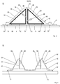
- FIG. 3 shows a cross section through a second structure 61 according to the invention for producing a composite component 32 from a plurality of textile semi-finished products positioned in an open mold 4.
- the composite component 32 is shown as a T-shaped stiffening element 36.
- a gas reservoir 64, 66 is positioned in gas receiving spaces 54, 62, which also act as shaping elements for the stiffening element 36 in addition to storing the volatile substances taken up from the matrix material or the structure.
- no suction 52 provided (with respect to suction s. FIG. 5 ).
- the gas accommodating spaces 54, 62 extend laterally of the stiffening element 36 over its entire axial length and are essentially delimited by its foot section 40, its web 44 and in each case by a film section 56, 68 of a vacuum film 10.
- the gas accommodating spaces 54, 62 have a triangular cross section.
- a sealing element 60 is arranged on the side of the foot section 40 on a tool surface 2, on which the vacuum film 10 engages.
- at least one suction 14 is arranged laterally of the foot portion 40.
- at least one sprue 14 is positioned laterally of the foot portion 40.
- the gas reservoirs 64, 66 have a triangular cross-section corresponding to the gas accommodating spaces 54, 56 and have an open-pore material structure for storing the residual air displaced from the composite component 32 into the gas accommodating spaces 54, 62.
- the gas reservoirs 64, 66 are in contact with and in contact with the stiffening element 36 located contact surfaces 70, 72, 74, 76 provided with a semipermeable membrane 58, 78.
- the gas receiving chambers 56, 62 forming membranes 58, 78 are connected to the gas storage 58, 78, whereby these directly form the gas receiving spaces 56, 62.
- the membranes 58, 78 extend over an outer surface 80, 82 facing the respective film section 56, 68 of the vacuum film 10, so that the gas reservoirs 64, 66 at least in the region of their side surfaces 70, 72, 80 and 74, 76, 82 with each one of the membranes 58, 78 are provided.
- the membranes 58, 78 are detachably attached to the gas reservoirs 64, 66, so that they can be exchanged for functional membranes 58, 78 when exhausted.
- the gas receiving chambers 56, 62 with a membrane 58, 78 can be shut off from the matrix material and the gas reservoirs 64, 66 then be positioned with their free side surfaces 70, 72, 74, 76, 80, 82 in these.
- membranes 58, 78 are in the FIG. 3 and also in particular in the FIGS. 4 and 5 shown spaced from the foot portion 44 and the web 40 via a respective gap.
- the chamber walls 56, 68 shown by the gas reservoirs 64, 64 and the outer surface side membrane portions spaced in each case over a gap.
- the gas-permeable properties of the membranes 58, 78 When evacuating the composite component 32 to be infiltrated via the exhaust 14, the gas-permeable properties of the membranes 58, 78 also evacuate the gas pockets 54, 62 and thus the gas reservoirs 64, 66, so that the structure 61 has a uniform negative pressure relative to its outer environment 84 .
- the vacuum in the gas pockets 54, 62 remains, so that the gas reservoirs 64, 66 can hold the residual air remaining in the structure (see arrows 86, 88).
- FIG. 4 Transferred to a composite member 32 to be infiltrated having a plurality of spaced-apart stiffening members 36, 38 means as in FIG. 4 greatly simplified shows that the stiffening elements 36, 38 are stabilized by the dimensionally stable and acting as shaping elements gas reservoirs 64, 66 and between the stiffening elements 36, 38 no gas receiving space 54, 62 formed or gas storage 64, 66 is arranged, so that despite a local or partial arrangement of the gas storage 64, 66 a surface escape of the residual air from the composite component 32 is made possible.
- FIG. 5 shows a third structure according to the invention 89.
- This structure 91 is based on that in the FIGS. 3 and 4 explained second construction 61 and has as a single difference in each case a gas storage 64, 66 associated with suction (arrows 52, 90), via which the volatile substances stored by the gas stores 64, 66 can be continuously or discontinuously led out of the structure 89.
Landscapes
- Engineering & Computer Science (AREA)
- Mechanical Engineering (AREA)
- Chemical & Material Sciences (AREA)
- Composite Materials (AREA)
- Architecture (AREA)
- Civil Engineering (AREA)
- Structural Engineering (AREA)
- Moulding By Coating Moulds (AREA)
- Casting Or Compression Moulding Of Plastics Or The Like (AREA)
Description
- Die Erfindung betrifft ein Infusionsverfahren in einem einseitig offenen Werkzeug nach dem Oberbegriff des Patentanspruchs 1 sowie einen Aufbau für ein Infusionsverfahren zur Herstellung eines faserverstärkten Verbundbauteils in einem einseitig offenen Werkzeug nach dem Oberbegriff des Patentanspruchs 8.
- Ein Aufbau eines bekannten Infusionsverfahrens zur Herstellung eines faserverstärkten Verbundbauteils in einem einseitig offenen Werkzeug ist in
Figur 1 gezeigt. Bei diesem Zweikammer-Aufbau 1, der dem in dem PatentDE 10013409C1 ausführlich beschriebenen Vakuum-Assisted-Process (VAP) zugrunde liegt, wird auf einer Oberfläche 2 eines einseitig offenen Werkzeugs 4 ein Bauteil 6 aus zumindest einem trockenen faserverstärktem Halbzeug, beispielsweise ein Fasergelege aus einer Vielzahl von Kohlenstofffasern, abgelegt. Das Werkzeug 4 ist in einer Vakuumkammer 8 angeordnet, die von einer das Bauteil 6 umhüllenden Vakuumfolie 10 gebildet ist und die sich über Dichtelemente 12 auf der Oberfläche 2 des Werkzeugs 4 abstützt. Die Evakuierung der Vakuumkammer 8 erfolgt über eine werkzeugnahe Absaugung 14. Zur Infiltrierung des Bauteils 6 mit einem Matrixmaterial, beispielsweise einem Epoxidharz, ist ein werkzeugferner Anguss 16 zur Zuführung des Harzes vorgesehen. Die Verteilung des Harzes über das Bauteil 6 erfolgt über eine globale, das Halbzeug 6 überspannende Fließhilfe 18, die über eine Lochfolie 20 und ein Abreißgewebe 22 von einer Bauteiloberfläche 24 beabstandet ist. Die Fließhilfe 18, die Lochfolie 20, das Abreißgewebe 22 sowie das Bauteil 6 sind von einer Membran 26 abgedeckt, die mit der Vakuumfolie 10 eine Luftkammer 28 begrenzt und über Dichtelemente 12 an der Werkzeugoberfläche 2 angreift. Die Membran 26 hat semipermeable Eigenschaften und weist meistens eine Struktur aus einem technischen Kunststoffmaterial auf. Sie ist für Gase bzw. flüchtige Stoffe durchlässig, hält jedoch Flüssigkeiten mit Viskositäten vergleichbar Wasser zurück. Diese semipermeablen Eigenschaften werden durch in der Membran 26 befindliche durchlässige Poren bzw. Maschen erreicht, welche mehr oder minder gleichmäßig auf der Membranoberfläche verteilt sind. Die Dicke der Membran bewegt sich gewöhnlich im Zehntel-Millimeterbereich. Im Prinzip schottet die Membran 26 den zu durchtränkenden Aufbau einschließlich der Fließhilfe 18 gegenüber der Vakuumfolie 10 ab, wobei durch die globale Luftkammer 28 eine flächige Vakuumverteilung auf der Oberfläche 24 des Halbzeugs 6 erzielt wird. Zur verbesserten bzw. gezielten Führung der Luft bzw. Gase in der Luftkammer 28 in Richtung der Absaugung 14 ist zwischen der Membran 26 und der Vakuumfolie 10 ein Belüftungsgewebe 30 angeordnet. - Diese bekannte Aufbau eignet sich jedoch nur begrenzt für die Herstellung komplexer Bauteile, da insbesondere die Membran ein hochkomplexer und sensibler Hilfsstoff ist, der bei fehlerhafter Drapierung seine semipermeablen Eigenschaften verliert sowie sehr schnell einreißen kann, so dass in dem herzustellenden Bauteil Fehlstellen generiert werden und die Bauteile somit eine mindere Qualität aufweisen. Darüber hinaus ist die Membran sehr teuer, so dass sich der Ersatz eingerissener bzw. geschädigter Membran unweigerlich in hohen Materialkosten wiederspiegelt.
- Die
US 2008 0093761 zeigt ein Infusionsverfahren zur Herstellung eines Rotorblattes einer Windenergieanlage.US 2008 0093761 beschreibt ein Verfahren zum Erzeugen eines länglichen Mantelteils aus einem Faser-Verbundwerkstoff mittels Vakuuminfusion, wobei das Fasermaterial mit flüssigem Polymer imprägniert ist, und Verwendung einer Form mit einem Formenhohlraum, in dem ein Fasereinsatz mit einer ersten Seitenflache und einer zweiten Seitenflache angeordnet wird, und wobei der Fasereinsatz ferner eine Vielzahl von Faserschichten und eine Verteilungsschicht aufweist, wobei die Verteilungsschicht eine höhere Durchflussrate für das flüssige Polymer als die Faserschichten zulasst, wobei eine halbdurchlässige Membran gegenüber der ersten Seitenflache des Fasereinsatzes angeordnet wird und die halbdurchlässige Membran für Gase im wesentlichen durchlässig und für flüssiges Polymer im wesentlichen undurchlässig ist und ferner mit einer Vakuumquelle kommuniziert, wobei die Verteilungsschicht im Inneren des Fasereinsatzes mit Faserschichten an beiden Seiten angeordnet wird und von einer Zone unterbrochen wird, wobei diese Zone gegenüber der halbdurchlässigen Membran positioniert ist, und dass flüssiges Polymer durch Einlasskanale zu der Verteilungsschicht geleitet wird und dadurch eine Strömungsfront zwischen der Verteilungsschicht und der zweiten Seitenflache erzeugt, wird, wobei sich diese Strömungsfront durch die Zone in Richtung zu der halbdurchlässigen Membran bewegt. - Aufgabe der vorliegenden Erfindung ist es, ein Infusionsverfahren sowie einen Aufbau für ein Infusionsverfahren in einem einseitig offenen Werkzeug zu schaffen, das die vorgenannten Nachteile beseitigt und die sichere Herstellung komplexer Bauteile mit wiederholbarer hoher Qualität ermöglicht.
- Diese Aufgabe wird gelöst durch ein Infusionsverfahren mit den Merkmalen des Patentanspruchs 1 und durch einen Aufbau für ein Infusionsverfahren mit den Merkmalen des Patentanspruchs 8.
- Bei einem erfindungsgemäßen Infusionsverfahren zur Herstellung eines faserverstärkten Verbundbauteils mit textilen Halbzeugen, die das von einem Matrixmaterial zu infiltrierende Verbundbauteil bilden, werden die Halbzeuge in einem einseitig offenen Werkzeug in einer zu evakuierenden Kammer angeordnet. Erfindungsgemäß wird zwischen dem Verbundbauteil und einer Kammerwandung zumindest ein lokaler Gasaufnahmeraum gebildet wird, der durch zumindest eine lokale gasdurchlässige Membran gegenüber dem Matrixmaterial abgesperrt wird, und in den beim Infiltrieren im Matrixmaterial und/oder im Aufbau enthaltene flüchtige Stoffe entweichen.
- Das erfindungsgemäß als Local-Assisted-Vacuum-Process (L-VAP) bezeichnete Verfahren eignet sich zur kostengünstigen Herstellung komplexer Bauteile in wiederholbarer hoher Qualität, da durch die lokale Gasaufnahmeraumbildung der Drapieraufwand der lokalen Membran bzw. lokalen Membranen vereinfacht wird und weiterhin großflächig flüchtige Bestandteile, die im Aufbau und im Harz enthalten sind, entweichen können. Die Ausbildung einer globalen, das zu fertigende Bauteil umspannenden Luftkammer entfällt, sondern es werden lediglich gezielte lokale bzw. partielle Gasaufnahmeräume gebildet, die die sichere Entnahme von im Aufbau und im Harz enthalten flüchtigen Bestandteilen wie Gase und Restluft ermöglichen, dank der lokalen Membranen das Matrixmaterial jedoch zurückgehalten wird. Das erfindungsgemäße Verfahren erlaubt zudem eine einfache Drapierung der zumindest einen Membran, so dass sie ihre gasdurchlässigen bzw. Matrixmaterial-blockierenden Eigenschaften nicht verliert bzw. diese nicht gemindert werden. Hierdurch wird die Gefahr von Fehlstellen innerhalb des Bauteils wesentlich verringert und somit die Bauteilqualität signifikant und wiederholbar gesteigert. Zudem ermöglicht das Verfahren den Verzicht auf eine während der Harzinfusion bestehende Absaugung, so dass der vorrichtungstechnische Aufwand reduziert wird. Weiterhin ist es bei der erfindungsgemäßen Lösung nicht mehr notwendig, die exakte Position des in Fließfronten von mehreren Seiten her zusammenlaufenden Matrixmaterials zu kennen.
- Um zu vermeiden, dass die Struktur der Membran nachteilig verändert wird und eventuell seine semipermeablen Eigenschaften verliert, wird die Membran vorzugsweise bei ebenen bzw. wenig gewölbten Flächen oder bei zwar stark jedoch nur einfach gekrümmten Oberflächen eingesetzt.
- Bei einem Ausführungsbeispiel wird der zumindest eine Gasaufnahmeraum beim Evakuieren der Kammer mit evakuiert. Hierdurch wird sichergestellt, dass der Gasaufnahmeraum frei von Gasen ist und eine maximales Aufnahmevolumen aufweist.
- Der zumindest eine Gasaufnahmeraum kann im Bereich von zusammenlaufenden Fließfronten angeordnet werden, so dass die von dem Matrixmaterial vor sich her getriebenen Gase verlässlich in den Gasaufnahmeraum getrieben werden.
- Gemäß der Erfindung wird in dem zumindest einen Gasaufnahmeraum zumindest ein formstabiler Gasspeicher angeordnet. Hierdurch wird verhindert, dass beim Evakuieren der Kammer das Aufnahmevolumen des Gasaufnahmeraums verkleinert wird. Zudem weist der Gasspeicher ein stabiles maximales Speichervolumen auf. Dabei kann die zumindest eine Membran direkt an dem Gasspeicher angeordnet sein, so dass der Gasspeicher den Gasaufnahmeraum unmittelbar bildet.
- Der zumindest eine Gasspeicher kann derart formstabil sein, dass er zur Stützung eines Bauteilbereichs eingesetzt werden kann. Der Gasspeicher wirkt bei dieser Variante als Druckstück bzw. Werkzeugkern, wodurch bei der Verwendung einer Vielzahl von derartigen Gasspeichern die Teileanzahl aufgrund der Multifunktionalität der Gasspeicher reduziert wird und trotz der lokalen Anordnung der Gasspeicher eine nahezu flächige Gasentnahme erfolgt. Zudem werden durch die Verwendung der Gasspeicher als Formgebungselemente Druckstellen auf dem Verbundbauteil vermieden.
- Bei einer kostengünstigen Variante wird der zumindest eine Gasspeicher mit einem geschlossenen bzw. versiegelten
Formgebungselement zur Stützung eines Bauteilbereichs kombiniert. - Die in den zumindest einen Gasaufnahmeraum bzw. den zumindest einen Gasspeicher entweichenden Gase können über eine Absaugung aus dem Gasaufnahmeraum bzw. dem Gasspeicher abgeführt werden. Hierdurch kann der Verlauf der Fließfronten gezielt gesteuert werden. Zudem können bspw. der zumindest eine Gasspeicher mit einem kleineren Speichervolumen ausgelegt werden.
- Ein erfindungsgemäßer Aufbau für ein Infusionsverfahren zur Herstellung eines faserverstärkten Verbundbauteils mit textilen Halbzeugen, die in einer zu evakuierenden Kammer in einem einseitig offenen Werkzeug abgelegt sind und das von einem Matrixmaterial zu infiltrierenden Verbundbauteil bilden, weist erfindungsgemäß zur Aufnahme von im Matrixmaterial und/oder im Aufbau enthaltenen flüchtigen Stoffen zumindest einen lokalen Gasaufnahmeraum zwischen dem Verbundbauteil und einer Kammerwandung auf, der durch zumindest eine lokale gasdurchlässige Membran gegenüber dem Matrixmaterial abgesperrt ist.
- Ein derartiger Aufbau eignet sich insbesondere zur kostengünstigen Herstellung komplexer Bauteile mit hoher reproduzierbarer Qualität, da der zumindest eine lokale Gasaufnahmeraum bzw. die partiellen Gasaufnahmeräume an Bauteilbereichen ausgebildet sein können, die eine einfache Geometrie wie zum Beispiel eine ebene bzw. nur leicht gekrümmte Oberfläche oder aber eine zwar stark jedoch nur einfach gekrümmte Oberfläche aufweisen. Ein Beispiel für eine einfach stark gekrümmte Oberfläche ist ein stufenförmiger bzw. rechtwinkliger Oberflächenverlauf wie im Anbindungsbereich von Versteifungselementenfüßen an Hautfeldern möglich. Hierdurch ist eine Beschädigung der lokalen Membran ausgeschlossen und somit eine optimale Funktionsfähigkeit der Membran gewährleistet. Zudem ist durch eine entsprechende Anzahl von Gasaufnahmeräumen eine großflächige Absaugung gewährleistet.
- Gemäß der Erfindung ist in dem zumindest einen Gasaufnahmeraum ein Gasspeicher positioniert, der die Speicherung
der flüchtigen Gase erlaubt. Die Erfindung zeichnet sich durch einen besonders einfachen Aufbau auf, da der Gasspeicher bzw. die Gasspeicher aufgrund seiner Robustheit nahezu flexibel an dem Halbzeug positioniert werden kann/können und die Bereitstellung einer individuellen Absaugung entfällt. Die Gasspeicher lassen sich bequem an gekrümmten oder kantigen bzw. stufenförmigen Bauteiloberflächen positionieren, ohne dass eine wesentliche Beeinträchtigung ihres Speichervolumens zu befürchten ist. Die Gasspeicher lassen sich individuell Formen bspw. Zuschneiden, Fräsen oder Aufbohren und können somit optimal an den jeweiligen Bauteilbereich angepasst sein. Der zumindest eine Gasspeicher hat eine offenporige bzw. poröse Materialstruktur ähnlich einem Schwamm oder einem Schaum. Beispielhafte Ausführungsbeispiele sind ein offenporiger Metallschaum oder ein offenporiger Kunststoffschäum. - Bei einem Ausführungsbeispiel ist an einer einem Bauteilbereich zugewandten Kontaktfläche des zumindest einen Gasspeichers die Membran lösbar angeordnet. Hierdurch entfällt die Positionierung der Membran an dem Bauteilbereich, was die Montage bzw. den Drapiervorgang wesentlich vereinfacht. Dabei kann durch die lösbare Anordnung der Membran diese nach Erschöpfung einfach entfernt und gegen eine neue Membran ausgetauscht werden, ohne dass der Gasspeicher an sich zu entsorgen ist.
- Bevorzugterweise ist der zumindest eine Gasspeicher formstabil, so dass er bei einer Evakuierung der Kammer keiner Formveränderung unterliegt und sicher gestellt ist, dass er stets sein maximales Speichervolumen aufweist.
- Bei einem Ausführungsbeispiel bildet der zumindest eine Gasspeicher zumindest einen Abschnitt eines Formgebungselementes. Hierdurch wird die Teilevielfalt des Aufbaus reduziert und insbesondere kann trotz der gezielten lokalen Gasaufhahmeraumbildung eine großflächige Gasaufnahme erfolgen. Ein als Formgebungselement bzw. Druckstück besonders geeigneter
erfindungsgemäßer Gasspeicher hat eine feste Rahmenstruktur mit teilweise offenen und/oder durchlässigen Bereichen. Der Hohlraum kann beispielsweise über Bohrungen bzw. bohrungsartige Öffnungen in der Wandung zur Außenumgebung bereichsweise geöffnet sein. - Ebenso kann der Gasspeicher eine gitterartige Wandung aufweisen, über deren Gittermaschen eine Evakuierung des Hohlraums und eine Gasaufnahme erfolgen kann. Zu Vermeidung eines Harzeintritts durch die Öffnungen bzw. die Gittermaschen in den Hohlraum kann der jeweilige Gasspeicher mit jeweils einer Membran bespannt sein.
- Bei einem Ausführungsbeispiel steht der zumindest eine Gasaufnahmeraum bzw. der zumindest eine Gasspeicher mit einer Absaugung in Fluidverbindung, so dass bspw. die aus dem Matrixmaterial in die Gasaufnahmeräume entwichenen flüchtigen Stoffe bspw. einer Reinigung unterzogen werden können.
- Sonstige vorteilhafte Ausführungsbeispiele sind Gegenstand weiterer Unteransprüche.
- Im Folgenden werden bevorzugte Ausführungsbeispiele anhand schematischer stark vereinfachter Darstellungen näher erläutert. Es zeigen:
- Figur 1
- einen bekannten Aufbau eines Infusionsverfahrens,
- Figur 2
- einen Aufbau nach einem LocalAssisted-Vacuum-Process (L-VAP), der nicht Teil der Erfindung ist,
- Figur 3
- einen zweiten Aufbau nach dem erfindungsgemäßen Infusionsverfahren,
- Figur 4
- eine weitere Darstellung des zweiten Aufbaus, und
- Figur 5
- einen dritten Aufbau nach dem erfindungsgemäßen Infusionsverfahren.
-
Figur 2 zeigt einen Querschnitt durch einen Aufbau 31 zur Herstellung eines monolithischen faserverstärkten Verbundbauteils 32. Das zu fertigende Bauteil 32 besteht aus einer Vielzahl von trockenen Fasergelegen, Gewirken, Geweben oder ähnlichem und wird bei der Herstellung mit einem Matrixmaterial, beispielsweise einem Epoxid- oder Polyesterharz, über seinen Querschnitt getränkt. In dem gezeigten Ausführungsbeispiel ist das Bauteil 32 ein Hautfeld eines Flugzeugrumpfes, das von einem die Außenhaut des Flugzeugs bildenden Flächengebilde 34 und von das Flächengebilde 34 stabilisierenden Stringern 36, 38 gebildet wird. Die Stringer 36, 38 haben jeweils einen Fußabschnitt 40, 42, über den sie an dem Flächengebilde 34 angebacken werden, und jeweils einen mittig auf dem Fußabschnitt 40, 42 angeordneten Steg 44, 46. Die Krümmung des Flächengebildes 34 bzw. des Hautfeldes ist aus Gründen der Übersichtlichkeit nicht dargestellt. Ebenso sind inFigur 2 aus Gründen der Übersichtlichkeit keine die Stringer 36 während der Herstellung seitlich stabilisierende Formgebungselemente wie Werkzeugkerne bzw. Druckstücke gezeigt. - Das Bauteil 32 ist über das Flächengebilde 34 auf einer Oberfläche 2 eines einseitig geöffneten Werkzeugs 4 abgelegt und in einer von einer Vakuumfolie 10 gebildeten Vakuumkammer 8 positioniert. Die Vakuumfolie 10 umschließt das Halbzeug 6 und ist über an dem Werkzeug 4 angreifenden Dichtelementen 12 gegenüber der Außenumgebung abgedichtet.
- Die Zufuhr des Harzes in die Vakuumkammer 8 und somit zu dem zu fertigenden Bauteil 32 erfolgt über Angüsse 48, 50, die werkzeugfern im Bereich von Kopfabschnitten der Stege 44, 46 angeordnet sind. Zur Verteilung des Harzes über das Bauteil 32 ist eine globale Fließhilfe 18 auf dem Bauteil 32 angeordnet und über eine Lochfolie 20 sowie eine Vielzahl von einzelnen Abreißgeweben 22 von der Bauteiloberfläche 2 beabstandet.
- Die Absaugung von im Aufbau und im Harz sich befindenden Gasen bzw. flüchtigen Stoffen erfolgt über zumindest eine werkzeugnahe Absaugung 52, die in vertikaler Richtung betrachtet unterhalb der Angüsse 48, 50 zwischen den Fußabschnitten 40, 42 der Stringer 36, 38 angeordnet ist und durch ein ovale Umrandung zeichnerisch hervorgehoben ist. Dabei ist die Absaugung 52 bevorzugterweise im Bereich von zusammenlaufender Harzfronten bzw. Fließfronten positioniert, da diese die Restluft in der Vakuumkammer 8 und sonstige sich aus dem Harz lösenden Gasen quasi vor sich hertreiben. Die Absaugung 52 steht mit einem lokalen Gasaufnahmeraum 54 in Fluidverbindung, der zwischen einer Kammerwandung bzw. einem Folienabschnitt 56 und einer bauteilseitigen Membran 58 gebildet und seitlich von zumindest einem umlaufenden bzw. mehreren Dichtelementen 60 begrenzt ist, über das sich der Folienabschnitt 56 auf der Fließhilfe 18 abstützt. Die Membran 58 hat semipermeable Eigenschaften und erlaubt den Austritt der Restluft bzw. der Gase aus der Vakuumkammer 8 und dem Harz in den Gasaufnahmeraum 54, verhindert jedoch den Eintritt des Harzes. Somit sperrt die Membran 58 den Gasaufnahmeraum 54 gegenüber dem Harz ab, wodurch ein Abströmen des flüssigen Harzes in die Absaugung 52 verhindert wird.
- Bei einem Infusionsverfahren wird das zu fertigende Bauteil 32 gemäß dem Aufbau 31 eingepackt. Dann wird die Vakuumkammer 8 über die Absaugung 52 bzw. eine Vielzahl der Absaugungen 52 evakuiert und über die Angüsse 48, 50 das Harz zugeführt, das über die Fließhilfe 18 gleichmäßig über die Bauteiloberfläche 24 verteilt wird. Das Harz durchdringt die Stringer 36, 38 sowie das Flächengebilde 34 in vertikaler bzw. Dickenrichtung, wobei sich zwei aufeinander zu bewegende Fließfronten ausbilden (nicht gezeigt). Die Fließfronten treiben die sich im Aufbau 31 befindende Restluft sowie die in dem Harz enthaltenen Gase bzw. flüchtigen Stoffe vor sich her bis diese durch die jeweilige partielle semipermeable Membran 58 in die lokalen Gasaufnahmeräume 54 eintritt und dort abgesaugt wird. Beim Zusammentreffen der Fließfronten ist das Bauteil 32 vollständig mit dem Harz durchtränkt und über die Gasaufnahmeräume 54 entgast. Dabei wird durch die Membranen 58 verhindert, dass das flüssige Harz über die Gasaufnahmeräume 54 wieder aus dem Bauteil 32 gedrückt wird bzw. abfließt. Nach dem Durchtränken des Bauteils 32 wird dieses ausgehärtet und anschließend weiteren Bearbeitungsschritten wie einer Qualitätskontrolle zugeführt.
-
Figur 3 zeigt einen Querschnitt durch einen zweiten erfindungsgemäßen Aufbau 61 zur Herstellung eines Verbundbauteils 32 aus einer Vielzahl von in einem offenen Werkzeug 4 positionierten textilen Halbzeugen. Aus Gründen der Übersichtlichkeit ist das Verbundbauteil 32 als ein T-förmiges Versteifungselement 36 gezeigt. Im Wesentlichen Unterschied zum Aufbau 31 nachFigur 2 ist bei diesem Aufbau 61 in Gasaufnahmeräumen 54, 62 jeweils ein Gasspeicher 64, 66 positioniert, die neben einer Speicherung der aus dem Matrixmaterial bzw. dem Aufbau aufgenommenen flüchtigen Stoffe zudem als Formgebungselemente für das Versteifungselement 36 wirken. Zudem ist bei der inFigur 3 gezeigten Variante keine Absaugung 52 vorgesehen (bzgl. Absaugung s.Figur 5 ). - Die Gasaufnahmeräume 54, 62 erstrecken sich seitlich des Versteifungselements 36 über dessen gesamte axiale Länge und werden im Wesentlichen von dessen Fußabschnitt 40, dessen Steg 44 sowie jeweils einem Folienabschnitt 56, 68 einer Vakuumfolie 10 begrenzt. Somit weisen die Gasaufnahmeräume 54, 62 einen dreieckigen Querschnitt auf. Zum druckdichten Abschließen der Gasaufnahmeräume 54, 62 ist seitlich des Fußabschnittes 40 auf einer Werkzeugoberfläche 2 ein Dichtelement 60 angeordnet, an dem die Vakuumfolie 10 angreift. Zur Evakuierung des Aufbaus 61 ist seitlich des Fußabschnittes 40 zumindest eine Absaugung 14 angeordnet. Zur Infusion des Harzes ist seitlich des Fußabschnittes 40 zumindest ein Anguss 14 positioniert.
- Die Gasspeicher 64, 66 haben einen den Gasaufnahmeräumen 54, 56 entsprechenden dreieckigen Querschnitt und weisen eine offenporige Materialstruktur zur Speicherung der in die Gasaufnahmeräume 54, 62 aus dem Verbundbauteil 32 verdrängten Restluft auf. Um zu verhindern, dass deren Poren durch das Matrixmaterial zugesetzt werden, sind die Gasspeicher 64, 66 an ihren dem Versteifungselement 36 zugewandten und mit diesen sich in Kontakt befindenden Kontaktflächen 70, 72, 74, 76 mit einer semipermeablen Membran 58, 78 versehen. Somit sind die die Gasaufnahmeräume 56, 62 bildenden Membranen 58, 78 an die Gasspeicher 58, 78 angebunden, wodurch diese unmittelbar die Gasaufnahmeräume 56, 62 bilden. Zudem erstrecken sich die Membranen 58, 78 über eine dem jeweiligen Folienabschnitt 56, 68 der Vakuumfolie 10 zugewandte Außenfläche 80, 82, so dass die Gasspeicher 64, 66 zumindest im Bereich ihrer Seitenflächen 70, 72, 80 bzw. 74, 76, 82 mit jeweils einer der Membranen 58, 78 versehen sind. Dabei sind die Membranen 58, 78 lösbar an den Gasspeichern 64, 66 befestigt, so dass sie bei Erschöpfung gegen funktionsfähige Membranen 58, 78 ausgetauscht werden können. Selbstverständlich können jedoch auch die Gasaufnahmeräume 56, 62 mit einer Membran 58, 78 gegenüber dem Matrixmaterial abgesperrt sein und die Gasspeicher 64, 66 dann mit ihren freien Seitenflächen 70, 72, 74, 76, 80, 82 in diesen positioniert sein.
- Zur besseren Sichtbarmachung der Membranen 58, 78 sind diese in der
Figur 3 und auch insbesondere in denFiguren 4 und5 von dem Fußabschnitt 44 und dem Steg 40 über jeweils einen Spalt beabstandet dargestellt. Ebenso sind zur besseren Sichtbarmachung der Gasaufnahmeräume 54, 62 in derFigur 3 und auch insbesondere in denFiguren 4 und5 die Kammerwandungen 56, 68 von den Gasspeichern 64, 64 bzw. deren außenflächenseitigen Membranabschnitten über jeweils einen Spalt beabstandet dargestellt. - Bei einer Evakuierung des zu infiltrierenden Verbundbauteils 32 über die Absaugung 14 werden durch die gasdurchlässigen Eigenschaften der Membranen 58, 78 ebenfalls die Gasaufnahmeräume 54, 62 und somit die Gasspeicher 64, 66 evakuiert, so dass der Aufbau 61 einen gleichmäßigen Unterdruck gegenüber seiner Außenumgebung 84 aufweist. Bei der Infusion des Harzes über den bzw. die Angusse 16 bleibt der Unterdruck in den Gasaufnahmeräumen 54, 62 bestehen, so dass die Gasspeicher 64, 66 die in dem Aufbau verbleibende Restluft aufnehmen kann (s. Pfeile 86, 88).
- Übertragen auf ein zu infiltrierenden Verbundbauteil 32 mit einer Vielzahl von voneinander beabstandeten Versteifungselementen 36, 38 bedeutet dies wie in
Figur 4 stark vereinfacht gezeigt, dass die Versteifungselemente 36, 38 von den formstabilen und als Formgebungselemente wirkenden Gasspeichern 64, 66 stabilisiert werden und zwischen den Versteifungselementen 36, 38 kein Gasaufnahmeraum 54, 62 ausgebildet bzw. Gasspeicher 64, 66 angeordnet ist, so dass trotz einer lokalen bzw. partiellen Anordnung der Gasspeicher 64, 66 ein flächiges Entweichen der Restluft aus dem Verbundbauteil 32 ermöglicht wird. -
Figur 5 zeigt einen dritten erfindungsgemäßen Aufbau 89. Dieser Aufbau 91 basiert auf dem in denFiguren 3 und 4 erläuterten zweiten Aufbau 61 und weist als einzigen Unterschied jeweils eine einem Gasspeicher 64, 66 zugeordnete Absaugung (Pfeile 52, 90) auf, über die die von den Gasspeichern 64, 66 gespeicherten flüchtigen Stoffe kontinuierlich oder diskontinuierlich aus dem Aufbau 89 geführt werden können. - Offenbart ist ein Infusionsverfahren zur Herstellung eines faserverstärkten Verbundbauteils mit textilen Halbzeugen in einem offenen Werkzeug, bei dem zumindest ein lokaler Gasaufnahmeraum zur Aufnahme von im Matrixmaterial und/oder im Aufbau enthaltenen flüchtigen Stoffen wie Harzgase und Restluft ausgebildet wird, der über eine lokale semipermeable Membran zum Matrixmaterial abgesperrt ist, sowie ein Aufbau zur Durchführung eines derartigen Verfahrens.
-
- 1
- Aufbau
- 2
- Oberfläche
- 4
- Werkzeug
- 6
- Bauteil
- 8
- Vakuumkammer
- 10
- Vakuumfolie
- 12
- Dichtelement
- 14
- Absaugung (Auslass)
- 16
- Anguss (Einlass)
- 18
- Fließhilfe
- 20
- Lochfolie
- 22
- Abreißgewebe
- 24
- Oberfläche
- 26
- Membran
- 28
- Luftkammer
- 30
- Belüftungsgewebe
- 31
- Aufbau
- 32
- Bauteil
- 34
- Flächengebilde
- 36
- Stringer
- 38
- Stringer
- 40
- Fußabschnitt
- 42
- Fußabschnitt
- 44
- Steg
- 46
- Steg
- 48
- Anguss
- 50
- Anguss
- 52
- Absaugung
- 54
- Gasaufnahmeraum
- 56
- Kammerwandung
- 58
- Membran
- 60
- Dichtelement
- 61
- Aufbau
- 62
- Gasaufnahmeraum
- 64
- Gasspeicher
- 66
- Gasspeicher
- 68
- Kammerwandung
- 70
- Kontaktfläche
- 72
- Kontaktfläche
- 74
- Kontaktfläche
- 76
- Kontaktfläche
- 78
- Membran
- 80
- Außenfläche
- 82
- Außenfläche
- 84
- Außenumgebung
- 86
- Pfeil Restluft
- 88
- Pfeil Restluft
- 89
- Aufbau
- 90
- Pfeil Absaugung
Claims (11)
- Infusionsverfahren zur Herstellung eines faserverstärkten Verbundbauteils (32) mit textilen Halbzeugen, die in einem einseitig offenen Werkzeug (4) in einer zu evakuierenden Kammer (8) angeordnet werden und das von einem Matrixmaterial zu infiltrierende Verbundbauteil (32) bilden, wobei
zwischen dem Verbundbauteil (32) und einer Kammerwandung (56, 68) zumindest ein lokaler Gasaufnahmeraum (54, 62) gebildet wird, der durch zumindest eine lokale gasdurchlässige Membran (58, 78) gegenüber dem Matrixmaterial abgesperrt wird und in den beim Infiltrieren im Matrixmaterial und/oder im Aufbau (31; 61; 89) enthaltene flüchtige Stoffe entweichen, dadurch gekennzeichnet, dass in dem Gasaufnahmeraum (54, 62) zumindest ein formstabiler Gasspeicher (64, 66) angeordnet wird, und wobei der formstabile Gasspeicher (64, 66) eine offenporige Materialstruktur hat. - Infusionsverfahren nach Anspruch 1, wobei die Membran (58, 80) an ebenen bis wenig gewölbten Bauteilflachen positioniert wird.
- Infusionsverfahren nach Anspruch 1 oder 2, wobei der Gasaufnahmeraum (54, 62) beim Evakuieren der Kammer (8) evakuiert wird.
- Infusionsverfahren nach Anspruch 1, 2 oder 3, wobei der Gasaufnahmeraum (54, 62) im Bereich zusammenlaufender Fließfronten angeordnet wird.
- Infusionsverfahren nach Anspruch 4, wobei der Gasspeicher (64, 66) zur Stützung eines Bauteilbereichs (40, 44) eingesetzt wird.
- Infusionsverfahren nach Anspruch 5, wobei der Gasspeicher (64, 66) mit einem geschlossenen Formgebungselement zur Stützung eines Bauteilbereichs (40, 44) kombiniert wird.
- Infusionsverfahren nach einem der vorhergehenden Ansprüche, wobei die Gase dem Gasaufnahmeraum (54, 62) über eine Absaugung (52, 90) entnommen werden.
- Aufbau (31; 61; 89) für ein Infusionsverfahren zur Herstellung eines faserverstärkten Verbundbauteils (32) mit textilen Halbzeugen, die in einer zu evakuierenden Kammer (8) in einem einseitig offenen Werkzeug (4) abgelegt sind und das von einem Matrixmaterial zu infiltrierenden Verbundbauteil (32) bilden, wobei zur Aufnahme von im Matrixmaterial und/oder im Aufbau (31; 61; 89) enthaltenen flüchtigen Stoffen zumindest ein lokaler Gasaufnahmeraum (54, 62) zwischen dem Verbundbauteil (32) und einer Kammerwandung (56, 68) gebildet ist, der durch zumindest eine lokale gasdurchlässige Membran (58, 78) gegenüber dem Matrixmaterial abgesperrt ist, dadurch gekennzeichnet, dass in dem Gasaufnahmeraum (54, 62) zumindest ein formstabiler Gasspeicher (64, 66) positioniert ist, und wobei der formstabile Gasspeicher (64, 66) eine offenporige Materialstruktur aufweist.
- Aufbau nach Anspruch 8, wobei an einer einem Bauteilbereich (40, 44) zugewandten Kontaktfläche (70, 72, 74, 76) die Membran (58, 78) lösbar angeordnet ist.
- Aufbau nach Anspruch 9, wobei der Gasspeicher (64, 66) zumindest ein Abschnitt eines Formgebungselementes ist.
- Aufbau nach einem der Ansprüche 8 bis10, wobei der Gasaufnahmeraum (54, 62) mit einer Absaugung (52, 90) in Fluidverbindung steht.
Applications Claiming Priority (4)
| Application Number | Priority Date | Filing Date | Title |
|---|---|---|---|
| US29051509P | 2009-12-29 | 2009-12-29 | |
| DE102009060705 | 2009-12-29 | ||
| DE102010062871A DE102010062871A1 (de) | 2009-12-29 | 2010-12-12 | Infusionsverfahren und Aufbau eines Infusionsverfahrens |
| PCT/EP2010/070830 WO2011080289A1 (de) | 2009-12-29 | 2010-12-29 | Infusionsverfahren und aufbau eines infusionsverfahrens |
Publications (2)
| Publication Number | Publication Date |
|---|---|
| EP2519400A1 EP2519400A1 (de) | 2012-11-07 |
| EP2519400B1 true EP2519400B1 (de) | 2019-10-16 |
Family
ID=44311980
Family Applications (1)
| Application Number | Title | Priority Date | Filing Date |
|---|---|---|---|
| EP10799055.8A Active EP2519400B1 (de) | 2009-12-29 | 2010-12-29 | Infusionsverfahren und aufbau eines infusionsverfahrens |
Country Status (4)
| Country | Link |
|---|---|
| US (1) | US10213970B2 (de) |
| EP (1) | EP2519400B1 (de) |
| DE (1) | DE102010062871A1 (de) |
| WO (1) | WO2011080289A1 (de) |
Families Citing this family (13)
| Publication number | Priority date | Publication date | Assignee | Title |
|---|---|---|---|---|
| AT511113B1 (de) * | 2011-03-04 | 2013-09-15 | Facc Ag | Verfahren zur herstellung eines faserverbundbauteils und werkzeuganordnung hierfür |
| US9199419B2 (en) | 2012-10-31 | 2015-12-01 | The Boeing Company | System and method for facilitating fluid movement in close-molded composite parts |
| EP2829387B1 (de) | 2013-07-23 | 2016-09-07 | Airbus Operations GmbH | Granuliertes Material, das in einem flüssigen Verbundformverfahren verwendet wird |
| CN103496178B (zh) * | 2013-09-03 | 2016-01-13 | 航天特种材料及工艺技术研究所 | 一种泡沫加筋复合材料结构的真空共注射整体成型方法 |
| US9403350B2 (en) * | 2013-12-16 | 2016-08-02 | The Nordam Group, Inc. | Flash control metal bonding |
| JP7085803B2 (ja) * | 2017-04-28 | 2022-06-17 | 三菱重工業株式会社 | 複合材の成形方法及び複合材の成形装置 |
| US11326576B2 (en) * | 2017-07-27 | 2022-05-10 | Vestas Wind Systems A/S | Web foot for a shear web |
| GB2568958A (en) | 2017-12-04 | 2019-06-05 | Short Brothers Plc | Resin barrier device |
| EP3860837A1 (de) * | 2018-10-02 | 2021-08-11 | Covestro Intellectual Property GmbH & Co. KG | Infusionsvorrichtung und verfahren zur herstellung von faserverstärkten verbundbauteilen |
| CN111284038A (zh) * | 2018-12-07 | 2020-06-16 | 中航贵州飞机有限责任公司 | 一种无人机用带筋复合材料件的液态成型方法 |
| DE102019114710A1 (de) * | 2019-05-31 | 2020-12-03 | Airbus Operations Gmbh | Vorrichtung und Verfahren |
| CN113733601B (zh) * | 2021-08-24 | 2022-09-20 | 成都飞机工业(集团)有限责任公司 | 一种用于vari液体成型复合材料加筋壁板的导流方法 |
| JP7447185B2 (ja) * | 2022-06-10 | 2024-03-11 | 三菱重工業株式会社 | 複合材構造体の製造装置及び複合材構造体の製造方法 |
Family Cites Families (38)
| Publication number | Priority date | Publication date | Assignee | Title |
|---|---|---|---|---|
| US2913036A (en) * | 1956-08-10 | 1959-11-17 | Anthony Bros Fibre Glass Pool | Process and apparatus for molding large plastic structures |
| US4132755A (en) * | 1977-07-22 | 1979-01-02 | Jay Johnson | Process for manufacturing resin-impregnated, reinforced articles without the presence of resin fumes |
| US4816106A (en) * | 1984-12-13 | 1989-03-28 | Aeritalia Saipa - Gruppo Velivoli Da Trasporto | Method for the controlled curing of composites |
| US4902215A (en) * | 1988-06-08 | 1990-02-20 | Seemann Iii William H | Plastic transfer molding techniques for the production of fiber reinforced plastic structures |
| FR2632604B1 (fr) * | 1988-06-08 | 1991-07-12 | Aerospatiale | Cadre en materiau composite notamment pour fuselage d'aeronef, et son procede de fabrication |
| FR2638673B1 (fr) * | 1988-11-08 | 1991-03-22 | Aerospatiale | Outillage pour le moulage de panneaux auto-raidis en materiau composite |
| US4917353A (en) * | 1988-11-15 | 1990-04-17 | The Boeing Company | Vacuum probe and method |
| US4942013A (en) * | 1989-03-27 | 1990-07-17 | Mcdonnell Douglas Corporation | Vacuum resin impregnation process |
| US5061542A (en) * | 1989-08-28 | 1991-10-29 | United Technologies Corporation | Stabilizing foam inserts for resin transfer molding |
| US5593633A (en) * | 1990-05-03 | 1997-01-14 | Dull; Kenneth M. | Edge and surface breather for high temperature composite processing |
| IT1262970B (it) * | 1992-08-03 | 1996-07-23 | Alenia Aeritalia & Selenia | Sistema per la realizzazione distrutture in fibra di carbonio, e procedimento per detto, particolarmente idoneo per applicazioni aeronautiche. |
| US5403537A (en) * | 1993-09-14 | 1995-04-04 | Martin Marietta Corporation | Method for forming composite structures |
| US5709893A (en) * | 1995-06-06 | 1998-01-20 | The Boeing Company | Breathable tooling for forming parts from volatile-emitting composite materials |
| DE19536675C1 (de) * | 1995-09-30 | 1997-02-20 | Deutsche Forsch Luft Raumfahrt | Vorrichtung und Verfahren zur Herstellung von großflächigen Bauelementen nach dem RTM-Verfahren |
| JPH10146898A (ja) * | 1996-11-15 | 1998-06-02 | Honda Motor Co Ltd | 繊維強化複合材の成形方法 |
| US6523246B1 (en) * | 1999-11-26 | 2003-02-25 | Honda Giken Kogyo Kabushiki Kaisha | Jig used for formation of fiber-reinforced composite structure and method for formation of fiber-reinforced composite structure using jig |
| WO2001041993A2 (en) * | 1999-12-07 | 2001-06-14 | The Boeing Company | Double bag vacuum infusion process and system for low cost, advanced composite fabrication |
| US6818159B2 (en) * | 2000-03-17 | 2004-11-16 | Deutsches Zentrum Fuer Luft-Und Raumfahrt E.V. | Process for the production of a composite consisting of a fiber reinforced material |
| DE10013409C1 (de) | 2000-03-17 | 2000-11-23 | Daimler Chrysler Ag | Verfahren und Vorrichtung zur Herstellung von faserverstärkten Bauteilen mittels eines Injektionsverfahrens |
| JP4425424B2 (ja) * | 2000-05-01 | 2010-03-03 | 本田技研工業株式会社 | 繊維強化複合材からなるジョグル付き半硬化物品の製造方法、及びそれを用いた予備成形構造体の製造方法 |
| US6478922B1 (en) * | 2000-06-15 | 2002-11-12 | Alliant Techsystems Inc. | Method of manufacturing a composite structure using a conformable locating aperture system |
| JP4448242B2 (ja) * | 2000-09-05 | 2010-04-07 | 本田技研工業株式会社 | スティフンドパネル用成形補助治具 |
| US20030019567A1 (en) * | 2001-07-26 | 2003-01-30 | Burpo Steven J. | Vacuum assisted resin transfer method for co-bonding composite laminate structures |
| DE10156123B4 (de) * | 2001-11-16 | 2006-07-27 | Eads Deutschland Gmbh | Verfahren und Vorrichtung zur Herstellung von faserverstärkten Kunststoffbauteilen |
| DE10203976B4 (de) * | 2002-01-31 | 2006-07-27 | Eads Deutschland Gmbh | Entgasungs-Vorrichtung zur Entgasung von für die Herstellung von Faserverbund-Bauteilen vorgesehenem Matrix-Material |
| US6896841B2 (en) * | 2003-03-20 | 2005-05-24 | The Boeing Company | Molding process and apparatus for producing unified composite structures |
| DE10325694B4 (de) * | 2003-06-06 | 2005-10-27 | Eads Deutschland Gmbh | Verfahren zum Verkleben von Bauteilen und insbesondere von Faserverbundbauteilen |
| US7160498B2 (en) * | 2004-03-08 | 2007-01-09 | Tracker Marine, L.L.C. | Closed molding tool |
| US7357166B2 (en) * | 2004-11-24 | 2008-04-15 | The Boeing Company | Flexible mandrel for highly contoured composite stringer |
| DK176135B1 (da) * | 2004-11-30 | 2006-09-18 | Lm Glasfiber As | Vakuuminfusion ved hjælp af semipermeabel membran |
| DE602006000870T2 (de) * | 2006-05-26 | 2009-05-14 | Siemens Aktiengesellschaft | Verfahren und Gegenstand zum Formen eines Bauteils durch Transfergiessen von Harz (R.T.M.), wobei das Formteil zumindest teilweise ein faserverstärktes Laminat enthält |
| US20080136060A1 (en) * | 2006-12-08 | 2008-06-12 | Gkn Westland Aerospace, Inc. | System and method for forming and curing a composite structure |
| BRPI0809269B8 (pt) * | 2007-03-20 | 2023-03-28 | Mitsubishi Heavy Ind Ltd | Método de rtm auxiliada com vácuo, e método para produzir um produto moldado de plástico reforçado com fibra |
| US7727631B2 (en) * | 2007-06-07 | 2010-06-01 | General Electric Company | System and method of manufacture of multi-resin composite articles |
| DE102007061431B4 (de) * | 2007-12-20 | 2013-08-08 | Airbus Operations Gmbh | Verfahren zur Versteifung eines Faserverbundbauteils sowie Vakuummatte und Anordnung zur Herstellung eines versteiften Faserverbundbauteils |
| DE102008055771C5 (de) | 2008-11-04 | 2018-06-14 | Senvion Gmbh | Rotorblattgurt |
| FR2959694B1 (fr) * | 2010-05-10 | 2012-08-03 | Lorraine Construction Aeronautique | Dispositif pour la fabrication d'une piece composite par injection de resine |
| US20140166191A1 (en) * | 2012-12-14 | 2014-06-19 | Aurora Flight Sciences Corporation | Methods for combining components of varying stages of cure |
-
2010
- 2010-12-12 DE DE102010062871A patent/DE102010062871A1/de not_active Ceased
- 2010-12-29 US US13/519,947 patent/US10213970B2/en active Active
- 2010-12-29 EP EP10799055.8A patent/EP2519400B1/de active Active
- 2010-12-29 WO PCT/EP2010/070830 patent/WO2011080289A1/de not_active Ceased
Non-Patent Citations (1)
| Title |
|---|
| None * |
Also Published As
| Publication number | Publication date |
|---|---|
| WO2011080289A1 (de) | 2011-07-07 |
| US20130069286A1 (en) | 2013-03-21 |
| EP2519400A1 (de) | 2012-11-07 |
| DE102010062871A1 (de) | 2011-06-30 |
| US10213970B2 (en) | 2019-02-26 |
Similar Documents
| Publication | Publication Date | Title |
|---|---|---|
| WO2011080289A1 (de) | Infusionsverfahren und aufbau eines infusionsverfahrens | |
| EP2681037B1 (de) | Verfahren zur herstellung eines faserverbundbauteils | |
| EP1181149B1 (de) | Verfahren und vorrichtung zur herstellung von faserverstärkten bauteilen mittels eines injektionsverfahrens | |
| EP2585282B1 (de) | Formwerkzeug zur herstellung von faserverstärkten bauteilen | |
| EP1420940B1 (de) | Verfahren und vorrichtung zur herstellung von faserverstärkten bauteilen mittels eines injektionsverfahrens | |
| EP2181834B1 (de) | Verfahren zur Herstellung eines Rotorblattgurts | |
| EP2909013B1 (de) | Vorrichtung und verfahren zur herstellung eines rotorblattgurts | |
| DE102012110307B4 (de) | Verfahren zur Herstellung von Verbundmaterial-Bauteilen aus Kunststoff durch Hochdruck-Harztransferpressen und zugehöriges Hochdruck-Harztransferpressen-Werkzeug | |
| DE102014007869B4 (de) | Vorrichtung und Verfahren zum Infiltrieren von Fasermaterial mit Harz zur Herstellung eines Faserverbundbauteils | |
| EP2988922B1 (de) | Fliesshilfe für infusionsaufbau, infusionsaufbau mit fliesshilfe sowie verfahren zum infiltrieren von fasermaterial mit harz | |
| DE602006000870T2 (de) | Verfahren und Gegenstand zum Formen eines Bauteils durch Transfergiessen von Harz (R.T.M.), wobei das Formteil zumindest teilweise ein faserverstärktes Laminat enthält | |
| EP2435238A2 (de) | Vorrichtung und verfahren zur herstellung eines verbundbauteils | |
| EP2731794B1 (de) | Wabenkernstabilisierung für sandwich-bauteile | |
| DE19813104A1 (de) | Verfahren zur Herstellung von Faserverbundbauteilen | |
| DE102015007284B4 (de) | Verfahren zur Herstellung von Faserverbundbauteilen | |
| DE102021132136A1 (de) | Verfahren und Vorrichtung zur Herstellung keramischer Faserkomposite mit variabler Geometrie | |
| DE102015005492B4 (de) | Fließhilfe für einen Infusionsaufbau sowie Infusionsaufbau und Verfahren zum Infiltrieren eines Fasermaterials | |
| DE102019114329A1 (de) | Aufbau und Verfahren zur Fertigung von Bauteilen aus einem Kunststoff oder Verbundmaterial, insbesondere für Luft- und Raumfahrzeuge, sowie Hilfswerkzeug | |
| DE102015219960A1 (de) | Vorrichtung und Verfahren zum Herstellen eines Faserverbundbauteils | |
| EP3103627A1 (de) | Absaugung in harzinfusionsverfahren |
Legal Events
| Date | Code | Title | Description |
|---|---|---|---|
| PUAI | Public reference made under article 153(3) epc to a published international application that has entered the european phase |
Free format text: ORIGINAL CODE: 0009012 |
|
| 17P | Request for examination filed |
Effective date: 20120704 |
|
| AK | Designated contracting states |
Kind code of ref document: A1 Designated state(s): AL AT BE BG CH CY CZ DE DK EE ES FI FR GB GR HR HU IE IS IT LI LT LU LV MC MK MT NL NO PL PT RO RS SE SI SK SM TR |
|
| DAX | Request for extension of the european patent (deleted) | ||
| 17Q | First examination report despatched |
Effective date: 20160615 |
|
| STAA | Information on the status of an ep patent application or granted ep patent |
Free format text: STATUS: EXAMINATION IS IN PROGRESS |
|
| GRAP | Despatch of communication of intention to grant a patent |
Free format text: ORIGINAL CODE: EPIDOSNIGR1 |
|
| STAA | Information on the status of an ep patent application or granted ep patent |
Free format text: STATUS: GRANT OF PATENT IS INTENDED |
|
| INTG | Intention to grant announced |
Effective date: 20190211 |
|
| GRAJ | Information related to disapproval of communication of intention to grant by the applicant or resumption of examination proceedings by the epo deleted |
Free format text: ORIGINAL CODE: EPIDOSDIGR1 |
|
| STAA | Information on the status of an ep patent application or granted ep patent |
Free format text: STATUS: EXAMINATION IS IN PROGRESS |
|
| GRAP | Despatch of communication of intention to grant a patent |
Free format text: ORIGINAL CODE: EPIDOSNIGR1 |
|
| STAA | Information on the status of an ep patent application or granted ep patent |
Free format text: STATUS: GRANT OF PATENT IS INTENDED |
|
| INTC | Intention to grant announced (deleted) | ||
| INTG | Intention to grant announced |
Effective date: 20190625 |
|
| GRAS | Grant fee paid |
Free format text: ORIGINAL CODE: EPIDOSNIGR3 |
|
| GRAA | (expected) grant |
Free format text: ORIGINAL CODE: 0009210 |
|
| STAA | Information on the status of an ep patent application or granted ep patent |
Free format text: STATUS: THE PATENT HAS BEEN GRANTED |
|
| AK | Designated contracting states |
Kind code of ref document: B1 Designated state(s): AL AT BE BG CH CY CZ DE DK EE ES FI FR GB GR HR HU IE IS IT LI LT LU LV MC MK MT NL NO PL PT RO RS SE SI SK SM TR |
|
| REG | Reference to a national code |
Ref country code: GB Ref legal event code: FG4D Free format text: NOT ENGLISH |
|
| REG | Reference to a national code |
Ref country code: CH Ref legal event code: EP |
|
| REG | Reference to a national code |
Ref country code: DE Ref legal event code: R096 Ref document number: 502010016318 Country of ref document: DE |
|
| REG | Reference to a national code |
Ref country code: IE Ref legal event code: FG4D Free format text: LANGUAGE OF EP DOCUMENT: GERMAN |
|
| REG | Reference to a national code |
Ref country code: AT Ref legal event code: REF Ref document number: 1190865 Country of ref document: AT Kind code of ref document: T Effective date: 20191115 |
|
| REG | Reference to a national code |
Ref country code: NL Ref legal event code: MP Effective date: 20191016 |
|
| PGFP | Annual fee paid to national office [announced via postgrant information from national office to epo] |
Ref country code: FR Payment date: 20191220 Year of fee payment: 10 |
|
| REG | Reference to a national code |
Ref country code: LT Ref legal event code: MG4D |
|
| PG25 | Lapsed in a contracting state [announced via postgrant information from national office to epo] |
Ref country code: NO Free format text: LAPSE BECAUSE OF FAILURE TO SUBMIT A TRANSLATION OF THE DESCRIPTION OR TO PAY THE FEE WITHIN THE PRESCRIBED TIME-LIMIT Effective date: 20200116 Ref country code: GR Free format text: LAPSE BECAUSE OF FAILURE TO SUBMIT A TRANSLATION OF THE DESCRIPTION OR TO PAY THE FEE WITHIN THE PRESCRIBED TIME-LIMIT Effective date: 20200117 Ref country code: PL Free format text: LAPSE BECAUSE OF FAILURE TO SUBMIT A TRANSLATION OF THE DESCRIPTION OR TO PAY THE FEE WITHIN THE PRESCRIBED TIME-LIMIT Effective date: 20191016 Ref country code: SE Free format text: LAPSE BECAUSE OF FAILURE TO SUBMIT A TRANSLATION OF THE DESCRIPTION OR TO PAY THE FEE WITHIN THE PRESCRIBED TIME-LIMIT Effective date: 20191016 Ref country code: LV Free format text: LAPSE BECAUSE OF FAILURE TO SUBMIT A TRANSLATION OF THE DESCRIPTION OR TO PAY THE FEE WITHIN THE PRESCRIBED TIME-LIMIT Effective date: 20191016 Ref country code: FI Free format text: LAPSE BECAUSE OF FAILURE TO SUBMIT A TRANSLATION OF THE DESCRIPTION OR TO PAY THE FEE WITHIN THE PRESCRIBED TIME-LIMIT Effective date: 20191016 Ref country code: PT Free format text: LAPSE BECAUSE OF FAILURE TO SUBMIT A TRANSLATION OF THE DESCRIPTION OR TO PAY THE FEE WITHIN THE PRESCRIBED TIME-LIMIT Effective date: 20200217 Ref country code: BG Free format text: LAPSE BECAUSE OF FAILURE TO SUBMIT A TRANSLATION OF THE DESCRIPTION OR TO PAY THE FEE WITHIN THE PRESCRIBED TIME-LIMIT Effective date: 20200116 Ref country code: NL Free format text: LAPSE BECAUSE OF FAILURE TO SUBMIT A TRANSLATION OF THE DESCRIPTION OR TO PAY THE FEE WITHIN THE PRESCRIBED TIME-LIMIT Effective date: 20191016 Ref country code: ES Free format text: LAPSE BECAUSE OF FAILURE TO SUBMIT A TRANSLATION OF THE DESCRIPTION OR TO PAY THE FEE WITHIN THE PRESCRIBED TIME-LIMIT Effective date: 20191016 Ref country code: LT Free format text: LAPSE BECAUSE OF FAILURE TO SUBMIT A TRANSLATION OF THE DESCRIPTION OR TO PAY THE FEE WITHIN THE PRESCRIBED TIME-LIMIT Effective date: 20191016 |
|
| PGFP | Annual fee paid to national office [announced via postgrant information from national office to epo] |
Ref country code: GB Payment date: 20191220 Year of fee payment: 10 |
|
| PG25 | Lapsed in a contracting state [announced via postgrant information from national office to epo] |
Ref country code: IS Free format text: LAPSE BECAUSE OF FAILURE TO SUBMIT A TRANSLATION OF THE DESCRIPTION OR TO PAY THE FEE WITHIN THE PRESCRIBED TIME-LIMIT Effective date: 20200224 Ref country code: HR Free format text: LAPSE BECAUSE OF FAILURE TO SUBMIT A TRANSLATION OF THE DESCRIPTION OR TO PAY THE FEE WITHIN THE PRESCRIBED TIME-LIMIT Effective date: 20191016 Ref country code: RS Free format text: LAPSE BECAUSE OF FAILURE TO SUBMIT A TRANSLATION OF THE DESCRIPTION OR TO PAY THE FEE WITHIN THE PRESCRIBED TIME-LIMIT Effective date: 20191016 |
|
| PG25 | Lapsed in a contracting state [announced via postgrant information from national office to epo] |
Ref country code: AL Free format text: LAPSE BECAUSE OF FAILURE TO SUBMIT A TRANSLATION OF THE DESCRIPTION OR TO PAY THE FEE WITHIN THE PRESCRIBED TIME-LIMIT Effective date: 20191016 |
|
| REG | Reference to a national code |
Ref country code: DE Ref legal event code: R097 Ref document number: 502010016318 Country of ref document: DE |
|
| PG2D | Information on lapse in contracting state deleted |
Ref country code: IS |
|
| PG25 | Lapsed in a contracting state [announced via postgrant information from national office to epo] |
Ref country code: DK Free format text: LAPSE BECAUSE OF FAILURE TO SUBMIT A TRANSLATION OF THE DESCRIPTION OR TO PAY THE FEE WITHIN THE PRESCRIBED TIME-LIMIT Effective date: 20191016 Ref country code: EE Free format text: LAPSE BECAUSE OF FAILURE TO SUBMIT A TRANSLATION OF THE DESCRIPTION OR TO PAY THE FEE WITHIN THE PRESCRIBED TIME-LIMIT Effective date: 20191016 Ref country code: CZ Free format text: LAPSE BECAUSE OF FAILURE TO SUBMIT A TRANSLATION OF THE DESCRIPTION OR TO PAY THE FEE WITHIN THE PRESCRIBED TIME-LIMIT Effective date: 20191016 Ref country code: RO Free format text: LAPSE BECAUSE OF FAILURE TO SUBMIT A TRANSLATION OF THE DESCRIPTION OR TO PAY THE FEE WITHIN THE PRESCRIBED TIME-LIMIT Effective date: 20191016 Ref country code: IS Free format text: LAPSE BECAUSE OF FAILURE TO SUBMIT A TRANSLATION OF THE DESCRIPTION OR TO PAY THE FEE WITHIN THE PRESCRIBED TIME-LIMIT Effective date: 20200216 |
|
| REG | Reference to a national code |
Ref country code: CH Ref legal event code: PL |
|
| PLBE | No opposition filed within time limit |
Free format text: ORIGINAL CODE: 0009261 |
|
| STAA | Information on the status of an ep patent application or granted ep patent |
Free format text: STATUS: NO OPPOSITION FILED WITHIN TIME LIMIT |
|
| REG | Reference to a national code |
Ref country code: BE Ref legal event code: MM Effective date: 20191231 |
|
| PG25 | Lapsed in a contracting state [announced via postgrant information from national office to epo] |
Ref country code: IT Free format text: LAPSE BECAUSE OF FAILURE TO SUBMIT A TRANSLATION OF THE DESCRIPTION OR TO PAY THE FEE WITHIN THE PRESCRIBED TIME-LIMIT Effective date: 20191016 Ref country code: SM Free format text: LAPSE BECAUSE OF FAILURE TO SUBMIT A TRANSLATION OF THE DESCRIPTION OR TO PAY THE FEE WITHIN THE PRESCRIBED TIME-LIMIT Effective date: 20191016 Ref country code: SK Free format text: LAPSE BECAUSE OF FAILURE TO SUBMIT A TRANSLATION OF THE DESCRIPTION OR TO PAY THE FEE WITHIN THE PRESCRIBED TIME-LIMIT Effective date: 20191016 Ref country code: MC Free format text: LAPSE BECAUSE OF FAILURE TO SUBMIT A TRANSLATION OF THE DESCRIPTION OR TO PAY THE FEE WITHIN THE PRESCRIBED TIME-LIMIT Effective date: 20191016 |
|
| 26N | No opposition filed |
Effective date: 20200717 |
|
| PG25 | Lapsed in a contracting state [announced via postgrant information from national office to epo] |
Ref country code: LU Free format text: LAPSE BECAUSE OF NON-PAYMENT OF DUE FEES Effective date: 20191229 Ref country code: IE Free format text: LAPSE BECAUSE OF NON-PAYMENT OF DUE FEES Effective date: 20191229 |
|
| PG25 | Lapsed in a contracting state [announced via postgrant information from national office to epo] |
Ref country code: BE Free format text: LAPSE BECAUSE OF NON-PAYMENT OF DUE FEES Effective date: 20191231 Ref country code: SI Free format text: LAPSE BECAUSE OF FAILURE TO SUBMIT A TRANSLATION OF THE DESCRIPTION OR TO PAY THE FEE WITHIN THE PRESCRIBED TIME-LIMIT Effective date: 20191016 Ref country code: CH Free format text: LAPSE BECAUSE OF NON-PAYMENT OF DUE FEES Effective date: 20191231 Ref country code: LI Free format text: LAPSE BECAUSE OF NON-PAYMENT OF DUE FEES Effective date: 20191231 |
|
| PG25 | Lapsed in a contracting state [announced via postgrant information from national office to epo] |
Ref country code: CY Free format text: LAPSE BECAUSE OF FAILURE TO SUBMIT A TRANSLATION OF THE DESCRIPTION OR TO PAY THE FEE WITHIN THE PRESCRIBED TIME-LIMIT Effective date: 20191016 |
|
| PG25 | Lapsed in a contracting state [announced via postgrant information from national office to epo] |
Ref country code: HU Free format text: LAPSE BECAUSE OF FAILURE TO SUBMIT A TRANSLATION OF THE DESCRIPTION OR TO PAY THE FEE WITHIN THE PRESCRIBED TIME-LIMIT; INVALID AB INITIO Effective date: 20101229 Ref country code: MT Free format text: LAPSE BECAUSE OF FAILURE TO SUBMIT A TRANSLATION OF THE DESCRIPTION OR TO PAY THE FEE WITHIN THE PRESCRIBED TIME-LIMIT Effective date: 20191016 |
|
| GBPC | Gb: european patent ceased through non-payment of renewal fee |
Effective date: 20201229 |
|
| PG25 | Lapsed in a contracting state [announced via postgrant information from national office to epo] |
Ref country code: FR Free format text: LAPSE BECAUSE OF NON-PAYMENT OF DUE FEES Effective date: 20201231 |
|
| PG25 | Lapsed in a contracting state [announced via postgrant information from national office to epo] |
Ref country code: GB Free format text: LAPSE BECAUSE OF NON-PAYMENT OF DUE FEES Effective date: 20201229 |
|
| PG25 | Lapsed in a contracting state [announced via postgrant information from national office to epo] |
Ref country code: TR Free format text: LAPSE BECAUSE OF FAILURE TO SUBMIT A TRANSLATION OF THE DESCRIPTION OR TO PAY THE FEE WITHIN THE PRESCRIBED TIME-LIMIT Effective date: 20191016 |
|
| PG25 | Lapsed in a contracting state [announced via postgrant information from national office to epo] |
Ref country code: MK Free format text: LAPSE BECAUSE OF FAILURE TO SUBMIT A TRANSLATION OF THE DESCRIPTION OR TO PAY THE FEE WITHIN THE PRESCRIBED TIME-LIMIT Effective date: 20191016 |
|
| PGFP | Annual fee paid to national office [announced via postgrant information from national office to epo] |
Ref country code: AT Payment date: 20231221 Year of fee payment: 14 |
|
| PGFP | Annual fee paid to national office [announced via postgrant information from national office to epo] |
Ref country code: DE Payment date: 20241210 Year of fee payment: 15 |
|
| REG | Reference to a national code |
Ref country code: AT Ref legal event code: MM01 Ref document number: 1190865 Country of ref document: AT Kind code of ref document: T Effective date: 20241229 |
|
| PG25 | Lapsed in a contracting state [announced via postgrant information from national office to epo] |
Ref country code: AT Free format text: LAPSE BECAUSE OF NON-PAYMENT OF DUE FEES Effective date: 20241229 |