EP2518899A2 - Single-trigger low-energy flip-flop circuit - Google Patents
Single-trigger low-energy flip-flop circuit Download PDFInfo
- Publication number
- EP2518899A2 EP2518899A2 EP12165817A EP12165817A EP2518899A2 EP 2518899 A2 EP2518899 A2 EP 2518899A2 EP 12165817 A EP12165817 A EP 12165817A EP 12165817 A EP12165817 A EP 12165817A EP 2518899 A2 EP2518899 A2 EP 2518899A2
- Authority
- EP
- European Patent Office
- Prior art keywords
- trigger
- circuit
- flop circuit
- low
- clock
- Prior art date
- Legal status (The legal status is an assumption and is not a legal conclusion. Google has not performed a legal analysis and makes no representation as to the accuracy of the status listed.)
- Granted
Links
Images



Classifications
-
- H—ELECTRICITY
- H03—ELECTRONIC CIRCUITRY
- H03K—PULSE TECHNIQUE
- H03K3/00—Circuits for generating electric pulses; Monostable, bistable or multistable circuits
- H03K3/02—Generators characterised by the type of circuit or by the means used for producing pulses
- H03K3/26—Generators characterised by the type of circuit or by the means used for producing pulses by the use, as active elements, of bipolar transistors with internal or external positive feedback
- H03K3/28—Generators characterised by the type of circuit or by the means used for producing pulses by the use, as active elements, of bipolar transistors with internal or external positive feedback using means other than a transformer for feedback
- H03K3/281—Generators characterised by the type of circuit or by the means used for producing pulses by the use, as active elements, of bipolar transistors with internal or external positive feedback using means other than a transformer for feedback using at least two transistors so coupled that the input of one is derived from the output of another, e.g. multivibrator
- H03K3/286—Generators characterised by the type of circuit or by the means used for producing pulses by the use, as active elements, of bipolar transistors with internal or external positive feedback using means other than a transformer for feedback using at least two transistors so coupled that the input of one is derived from the output of another, e.g. multivibrator bistable
-
- H—ELECTRICITY
- H03—ELECTRONIC CIRCUITRY
- H03K—PULSE TECHNIQUE
- H03K3/00—Circuits for generating electric pulses; Monostable, bistable or multistable circuits
- H03K3/02—Generators characterised by the type of circuit or by the means used for producing pulses
- H03K3/353—Generators characterised by the type of circuit or by the means used for producing pulses by the use, as active elements, of field-effect transistors with internal or external positive feedback
- H03K3/356—Bistable circuits
-
- H—ELECTRICITY
- H03—ELECTRONIC CIRCUITRY
- H03K—PULSE TECHNIQUE
- H03K3/00—Circuits for generating electric pulses; Monostable, bistable or multistable circuits
- H03K3/01—Details
- H03K3/012—Modifications of generator to improve response time or to decrease power consumption
-
- H—ELECTRICITY
- H03—ELECTRONIC CIRCUITRY
- H03K—PULSE TECHNIQUE
- H03K3/00—Circuits for generating electric pulses; Monostable, bistable or multistable circuits
- H03K3/02—Generators characterised by the type of circuit or by the means used for producing pulses
- H03K3/027—Generators characterised by the type of circuit or by the means used for producing pulses by the use of logic circuits, with internal or external positive feedback
- H03K3/037—Bistable circuits
-
- H—ELECTRICITY
- H03—ELECTRONIC CIRCUITRY
- H03K—PULSE TECHNIQUE
- H03K3/00—Circuits for generating electric pulses; Monostable, bistable or multistable circuits
- H03K3/02—Generators characterised by the type of circuit or by the means used for producing pulses
- H03K3/353—Generators characterised by the type of circuit or by the means used for producing pulses by the use, as active elements, of field-effect transistors with internal or external positive feedback
- H03K3/356—Bistable circuits
- H03K3/356104—Bistable circuits using complementary field-effect transistors
- H03K3/356113—Bistable circuits using complementary field-effect transistors using additional transistors in the input circuit
- H03K3/35613—Bistable circuits using complementary field-effect transistors using additional transistors in the input circuit the input circuit having a differential configuration
- H03K3/356139—Bistable circuits using complementary field-effect transistors using additional transistors in the input circuit the input circuit having a differential configuration with synchronous operation
-
- H—ELECTRICITY
- H03—ELECTRONIC CIRCUITRY
- H03K—PULSE TECHNIQUE
- H03K3/00—Circuits for generating electric pulses; Monostable, bistable or multistable circuits
- H03K3/02—Generators characterised by the type of circuit or by the means used for producing pulses
- H03K3/353—Generators characterised by the type of circuit or by the means used for producing pulses by the use, as active elements, of field-effect transistors with internal or external positive feedback
- H03K3/356—Bistable circuits
- H03K3/356104—Bistable circuits using complementary field-effect transistors
- H03K3/356182—Bistable circuits using complementary field-effect transistors with additional means for controlling the main nodes
- H03K3/356191—Bistable circuits using complementary field-effect transistors with additional means for controlling the main nodes with synchronous operation
Definitions
- the present invention generally relates to digital flip-flop circuits and more specifically to a single-trigger low-energy flip-flop circuit that is fully-static and insensitive to fabrication process variations.
- Power dissipation is a significant problem in conventional integrated circuits.
- a large fraction of the power dissipated in conventional digital integrated circuits is consumed in the clock network.
- the amount of energy that is consumed by flip-flops due to data transitions is small because the activity factor, the fraction of time the data input of the flip-flop toggles, is quite low, typically about 5-10%.
- the clock input load and clock energy is an increasingly important metric to consider when determining the energy that is consumed by the latches and flip-flops in a conventional integrated circuit. Reducing the clock-switched capacitance by a given amount produces 10x the power savings compared with reducing the data-switched capacitance by the same amount.
- Figure 1 illustrates a conventional flip-flop circuit 100.
- the flip-flop circuit 100 includes 26 transistors, including the inverters used to generate clkN and clkP.
- Each of the clock signals, clkP has a load of four transistor devices and clkN ha a load of six transistor devices.
- 12 transistor gates (and corresponding wires) toggle, including the gates coupled to the clk signal.
- Figure 2 illustrates another conventional flip-flop circuit 200 that is sometimes referred to as the StrongARM flip-flop.
- the total clock load presented to Clk 220 of the flip-flop circuit 200 is only three transistor devices.
- the total number of transistors in the flip-flop circuit 200 is twenty, where each NAND gate includes four transistors.
- half of the internal nodes toggle each clock cycle.
- the internal nodes include the gates that are coupled to Clk 220 and the node 210.
- the node 210 is coupled to four transistor gates and three transistor sources or drains.
- the total number of internal nodes that toggle each clock cycle is seven gates and ten transistor sources or drains or the equivalent of approximately seventeen gate loads.
- flip-flop circuit that reduces the energy consumed by reducing the number of internal nodes that toggle during a clock cycle. Additionally, the flip-flop circuit should function independent of fabrication process variations by not relying on sizing relationships between different transistors in the flip-flop circuit.
- One embodiment of the present invention sets forth a technique for capturing and storing a level of an input signal using a single-trigger, low-energy flip-flop circuit that is fully-static and insensitive to fabrication process variations.
- the single-trigger, low-energy flip-flop circuit presents only three transistor gate loads to the clock signal and none of the internal nodes toggle when the input signal remains constant.
- One of the clock signals may be a low-frequency "keeper clock" that toggles less frequently than the other two clock signals that are input to two transistor gates.
- Various embodiments of the invention comprise a single-trigger low-energy flip-flop circuit including a trigger sub-circuit and a latch sub-circuit.
- the trigger sub-circuit includes a first clock-activated transistor and is configured to arm a trigger signal when an input signal to the single-trigger low-energy flip-flop circuit is at a different level than a level of an output signal generated by the single-trigger low-energy flip-flop circuit.
- the latch sub-circuit includes a second clock-activated transistor and is configured to change the level of the output signal when the trigger signal is armed and a clock signal transitions from a first level to a second level and maintain the level of the output signal when the trigger signal is unarmed.
- One advantage of the disclosed single-trigger low-energy flip-flop circuit is that the transistor device load on the clock signal is reduced to only three transistor gates. Therefore, the clock energy is reduced significantly compared with flip-flop circuits having greater loads on the clock signal. Additionally, the internal nodes are driven high or low during stable states of the circuit to produce a fully static design that does not rely on sizing relationships between the different transistors, such as transistors configured as sense amplifiers. Therefore, the single-trigger low-energy flip-flop circuit operation is robust, even when the characteristics of the transistors vary due to the fabrication process.
- Figure 1 illustrates a conventional flip-flop circuit, according to the prior art
- Figure 2 illustrates another conventional flip-flop circuit, according to the prior art
- Figure 3 illustrates a single-trigger low-energy flip-flop circuit, according to one embodiment of the invention
- Figure 4 is a transition map diagram showing legal transitions for the single-trigger low-energy flip-flop circuit for each combination of input signals, in accordance with one or more aspects of the present invention
- FIG. 5 is a block diagram illustrating a processor/chip including the single-trigger low-energy flip-flop circuit shown in Figure 3 , in accordance with one or more aspects of the present invention.
- Figure 6 is a block diagram illustrating a computer system configured to implement one or more aspects of the present invention.
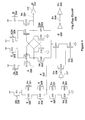
- FIG. 3 illustrates a single-trigger low-energy flip-flop circuit 300, according to one embodiment of the invention.
- the flip-flop circuit 300 is a fully-static, clock-energy efficient flip-flop that presents only three loads to the clock and does not depend on transistor device size relationships.
- transistors 306, 307, 308, 309, 318, 319, 320, 321, 322, 323, and 324 are NMOS devices and transistors 301, 302, 303, 304, 305, 310, 311, 312, 313, 314, 315, 316, and 317 are PMOS devices.
- the flip-flop circuit 300 includes four main sub-circuits, a single trigger sub-circuit, an output buffer, and a latch.
- Transistors 301, 302, 303, 304, 305, 306, 307, 308, 309, 323, and inverter 327 are configured to form the single trigger sub-circuit.
- the single trigger circuit When the input signal Dd 333 changes to a level that is different than the level of the output Q 337 when the Clk 330 is low, the single trigger circuit is "armed," i.e., configured to set or reset the output Q 337 at the next rising edge of the Clk 330. If Dd 333 changes value again, so that Dd 333 is the same level as Q 337 while the Clk 330 is still low, the armed trigger circuit is unarmed.
- the single trigger sub-circuit asserts the trigger signal, pulling E 332 up to a high level, when the input signal Dd 333 is low and Q 337 is high and the Clk 330 is low. A reset is triggered to force the output signal Q 337 to a low level when the Clk 330 transitions from low to high.
- the single trigger sub-circuit also asserts the trigger signal, pulling E 332 up to a high level, when the input signal Dd 333 is high and Q 337 is low and the clock is low. A set is triggered to force the output signal Q 337 to a high level when the clock 330 transitions from low to high.
- E 332 is low and En 336 is high.
- Transistors 310, 311, 312, 313, 314, 315, 316, 317, 318, 319, 320, 321, 322, and 324 are configured to form the latch circuit.
- Inverter 329 is configured to buffer the output of the latch and generate the flip-flop output Q 337.
- the latch circuit is enabled when the Clk 330 is high and transistor 324 is enabled.
- E 332 is low and the clock transitions from low to high, transistor 322 is disabled so that neither S 326 nor Sn 331 are changed.
- the inverter 327 and transistor 323 function as a keeper circuit to maintain E 332 low if any of the inputs (Dd 333, Dn 334, D 335, S 326, Sn 331) change while the Clk 330 is high.
- transistor 316 is enabled so that the latch maintains the level of output Q 337.
- Transistors 310 and 312 are configured to pull-up S 326 when Dn 334 and Sn 331 are both low, causing Q 337 to transition high.
- Transistors 311 and 313 are configured pull-up Sn 331 when Dd 333 and S 326 are both low, causing Q 337 to transition.
- Transistor 316 serves as a keeper after E 332 transitions low and until the Clk 330 transitions low. The D 335 input may change after transistor 316 is activated to keep the state of S 326 and Sn 331.
- the single trigger sub-circuit is armed when the Clk 330 rises, a state transition is triggered.
- the latch sub-circuit is set by pulling node sN 331 low via clock-enabled pull-down transistor 324 and transistor 322.
- the data input dN 334 should remain stable until the trigger signal, E 332 is deasserted (unarmed) to ensure that the hold time for the single-trigger low-energy flip-flop circuit 300 is met.
- D 335 to activate transistors 305 and 311 reduces the length of the hold time requirement, i.e., provides additional margin for the hold time.
- the invertor between Dn 334 and Dd 333 may be omitted and D 335 may replace Dd 333.
- E 332 When E 332 is deasserted (unarmed), transistor 316 is enabled so that the levels of S 326, Sn 331, and output Q 337are maintained. S 326, Sn 331, and output Q 337 will remain unchanged until the single-trigger sub-circuit is armed (E 332 is asserted) and Clk 330 rises.
- the triggering of a set occurs when E 332 and Clk 330 are high and the node Sn 331 is pulled low through transistor 321, node S 326 is then pulled up by transistors 312 and 310. Since the state transition was triggered by Dd 333 being high and Q 337 being low, the signal Dn 334 is guaranteed to be low. Sn 331 going low forces Q 337 high, effectively setting Q 337. The triggering of a reset proceeds in a similar manner. If E 332 is armed when Clk 330 rises and Dd 333 is low, node s 326 is pulled down through transistors 320, 322, and 324, which in turn pulls up node sN 331.
- the transistor 317 receives a keeper clock signal, kClk 338. It is not necessary to activate kclk 338 every clock cycle. It is sufficient for the keeper clock signal kclk to go low once every N cycles, where N is small enough so that charge is restored to the node shared by transistors 314, 315, 316, and 317. A value, N of 100, would suffice for most conditions and would result in the keeper clock load consuming only 1% of the energy of a clock load that toggled every cycle.
- the keeper clock signal kclk 338 should be gated high enough in the clock tree so that the clock load of an OR gate used to generate the keeper clock signal kclk 338 can be amortized over many flip-flop circuits 300.
- the keeper clock signal kclk 338 may be generated using a clock gating circuit that is described in patent application serial number 13/008,894 (Attorney Docket No. NVDA/SC-10-0317-US1) filed January 18, 2011, and titled "Low Energy Flip-Flops.”
- Figure 4 is a transition map diagram 400 showing legal transitions for the single-trigger low-energy flip-flop circuit 300 for each combination of input signals, in accordance with one or more aspects of the present invention.
- the behavior of the single-trigger flip-flop circuit 300 may be understood by considering each of the flip-flop circuits to be an asynchronous finite state machine and following the state transitions on the transition map 400.
- the transition map 400 plots the states of the input variables (D 335 and Clk 330) on the horizontal axis and the state variables (E 332 and S 326) on the vertical axis. All horizontal transitions are input stimulus. All vertical transitions are the response of the flip-flop circuit 300 to the input stimulus.
- the flip-flop circuit 300 has eight stable states labeled 401, 402, 403, 404, 405, 406, 407, and 408. There are six transient states labeled 411, 412, 413, 414, 415, and 416 that reflect the state of the circuit after an input change but before the circuit's response to that change.
- D 335 transitioning back to 0 will return the single-trigger flip-flop circuit 300 to state 401, negating E 332 and unarming the trigger. If D 335 toggles while Clk 330 is low, the flip-flop circuit 300 can cycle around the loop between states 401 and 402.
- the single-trigger flip-flop circuit flip-flop circuit 300 responds by asserting S 326, thereby triggering the set.
- the single-trigger flip-flop circuit 300 transitions from state 402 to the transient state 410 and immediately transitions to state 403 as S 326 rising causes E 332 to be pulled-down by the single trigger sub-circuit.
- the single-trigger flip-flop circuit 300 transitions to state 405.
- the single-trigger flip-flop circuit 300 transitions from state 406 to the transient state 409 and immediately transitions to state 407 as S 326 falling causes E 332 to be pulled-down by the single trigger sub-circuit.
- the single-trigger flip-flop circuit 300 transitions to state 401.
- the single-trigger flip-flop circuit 300 shows that all major nodes (E 332, En 336, S 326, and Sn 331) are driven either high or low in each of the eight stable states 401, 402, 403, 404, 405, 406, 407, and 408.
- the single-trigger flip-flop circuit 300 is fully static.
- Node S 326 is undriven briefly during the transient state 413 (on the way to transient state 410).
- node sN 331 is undriven briefly during the transient state 416 (on the way to transient state 409).
- these transient states 413 and 416 persist for only one or two gate delays, floating nodes in these states are not a concern.
- E 332 is high when the Clk 330 transitions from low to high, E 332 will be floating high, not driven high. E 332 is expected to remain high for a few gate delays until it is pulled low by transistors 306 and 308 or transistors 307 and 309. All nodes are driven in the transient states 411, 412, 413, and 415.
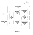
- FIG. 5 is a block diagram illustrating a processor/chip 540 including single-trigger flip-flop circuit 300 from Figure 3 , in accordance with one or more aspects of the present invention.
- I/O circuits 565 may include pads and other I/O specific circuits to send and receive signals from other devices in a system.
- Output signal 555 is produced by I/O circuits 565 based on signals received by the I/O circuits 565.
- the input signal 551 is received by the I/O circuits 565 and is input to the first single-trigger flip-flop circuit 300 for storage.
- the I/O circuits 565 also provide clock signals to the single-trigger flip-flop circuit 300.
- the combinational circuits 570 receive the output generated by the first single-trigger flip-flop circuit 300 and generate a combinational output that is received by the second single-trigger flip-flop circuit 300.
- the second single-trigger flip-flop circuit 300 stores the combinational output and generates an output that is input to the combinational circuits 572.
- the output of the combinational circuits 572 is received and stored by the third single-trigger flip-flop circuit 300.
- the third single-trigger flip-flop circuit 300 generates an output that is provided to the I/O circuits 565.
- the single-trigger flip-flop circuit 300 may be used to store signals for multiple clock cycles or to pipeline signals that change as frequently as each clock cycle.
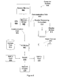
- FIG. 6 is a block diagram illustrating a computer system 100 configured to implement one or more aspects of the present invention.
- Computer system 600 includes a central processing unit (CPU) 602 and a system memory 604 communicating via a bus path through a memory bridge 605.
- Memory bridge 605 may be integrated into CPU 602 as shown in Figure 6 .
- memory bridge 605 may be a conventional device, e.g., a Northbridge chip, that is connected via a bus to CPU 602.
- Memory bridge 605 is connected via communication path 606 (e.g., a HyperTransport link) to an I/O (input/output) bridge 607.
- communication path 606 e.g., a HyperTransport link
- I/O bridge 607 which may be, e.g., a Southbridge chip, receives user input from one or more user input devices 608 (e.g., keyboard, mouse) and forwards the input to CPU 602 via path 606 and memory bridge 605.
- a parallel processing subsystem 612 is coupled to memory bridge 605 via a bus or other communication path 613 (e.g., a PCI Express, Accelerated Graphics Port, or HyperTransport link); in one embodiment parallel processing subsystem 612 is a graphics subsystem that delivers pixels to a display device 610 (e.g., a conventional CRT or LCD based monitor).
- a system disk 614 is also connected to I/O bridge 607.
- a switch 616 provides connections between I/O bridge 607 and other components such as a network adapter 618 and various add-in cards 620 and 621.
- Other components may also be connected to I/O bridge 607.
- Communication paths interconnecting the various components in Figure 6 may be implemented using any suitable protocols, such as PCI (Peripheral Component Interconnect), PCI-Express (PCI-E), AGP (Accelerated Graphics Port), HyperTransport, or any other bus or point-to-point communication protocol(s), and connections between different devices may use different protocols as is known in the art.
- the parallel processing subsystem 612 incorporates circuitry optimized for graphics and video processing, including, for example, video output circuitry, and constitutes a graphics processing unit (GPU).
- the parallel processing subsystem 612 incorporates circuitry optimized for general purpose processing, while preserving the underlying computational architecture, described in greater detail herein.
- the parallel processing subsystem 612 may be integrated with one or more other system elements, such as the memory bridge 605, CPU 602, and I/O bridge 607 to from a system on chip (SoC).
- SoC system on chip
- One or more of CPU 602, parallel processing sub-system 612, I/O bridge 607, and switch 616 may include a single-trigger low-energy flip-flop circuit 300 or 350.
- system memory 604 is connected to CPU 602 directly rather than through a bridge, and other devices communicate with system memory 604 via memory bridge 605 and CPU 602.
- parallel processing subsystem 612 is connected to I/O bridge 607 or directly to CPU 602, rather than to memory bridge 605.
- one or more of CPU 602, I/O bridge 607, parallel processing subsystem 612, and memory bridge 605 may be integrated into one or more chips.
- switch 616 is eliminated, and network adapter 618 and add-in cards 620, 621 connect directly to I/O bridge 607.
- the single-trigger low-energy flip-flop circuit 300 is fully static since all nodes are driven high or low during all stable states of the circuits.
- the single-trigger low-energy flip-flop circuit 300 is low energy since the internal nodes toggle only when the data changes and the loading of the clock is only three transistor gates. Additionally, the single-trigger low-energy flip-flop circuit 300 does not rely on sizing relationships between the different transistors to function properly. Therefore, the operation of single-trigger low-energy flip-flop circuit 300 is robust, even when the characteristics of the transistors vary due to the fabrication process.
- One embodiment of the invention may be implemented as a program product for use with a computer system.
- the program(s) of the program product define functions of the embodiments (including the methods described herein) and can be contained on a variety of computer-readable storage media.
- Illustrative computer-readable storage media include, but are not limited to: (i) non-writable storage media (e.g., read-only memory devices within a computer such as CD-ROM disks readable by a CD-ROM drive, flash memory, ROM chips or any type of solid-state non-volatile semiconductor memory) on which information is permanently stored; and (ii) writable storage media (e.g., floppy disks within a diskette drive or hard-disk drive or any type of solid-state random-access semiconductor memory) on which alterable information is stored.
- non-writable storage media e.g., read-only memory devices within a computer such as CD-ROM disks readable by a CD-ROM drive, flash memory, ROM
Landscapes
- Engineering & Computer Science (AREA)
- Power Engineering (AREA)
- Logic Circuits (AREA)
- Design And Manufacture Of Integrated Circuits (AREA)
- Electronic Switches (AREA)
Abstract
Description
- The present invention generally relates to digital flip-flop circuits and more specifically to a single-trigger low-energy flip-flop circuit that is fully-static and insensitive to fabrication process variations.
- Power dissipation is a significant problem in conventional integrated circuits. A large fraction of the power dissipated in conventional digital integrated circuits is consumed in the clock network. The amount of energy that is consumed by flip-flops due to data transitions is small because the activity factor, the fraction of time the data input of the flip-flop toggles, is quite low, typically about 5-10%. In contrast, the clock input load and clock energy is an increasingly important metric to consider when determining the energy that is consumed by the latches and flip-flops in a conventional integrated circuit. Reducing the clock-switched capacitance by a given amount produces 10x the power savings compared with reducing the data-switched capacitance by the same amount.
-
Figure 1 illustrates a conventional flip-flop circuit 100. The flip-flop circuit 100 includes 26 transistors, including the inverters used to generate clkN and clkP. Each of the clock signals, clkP has a load of four transistor devices and clkN ha a load of six transistor devices. At each clock transition, 12 transistor gates (and corresponding wires) toggle, including the gates coupled to the clk signal. -
Figure 2 illustrates another conventional flip-flop circuit 200 that is sometimes referred to as the StrongARM flip-flop. Compared with the flip-flop circuit 100, the total clock load presented toClk 220 of the flip-flop circuit 200 is only three transistor devices. The total number of transistors in the flip-flop circuit 200 is twenty, where each NAND gate includes four transistors.
However, half of the internal nodes toggle each clock cycle. The internal nodes include the gates that are coupled toClk 220 and thenode 210. Thenode 210 is coupled to four transistor gates and three transistor sources or drains. The total number of internal nodes that toggle each clock cycle is seven gates and ten transistor sources or drains or the equivalent of approximately seventeen gate loads. Suppose input d is high and all of the internal nodes are initially high (Vdd or a Vt drop below Vdd). When theClk 220 goes high both source and drain ofinput transistor 201 go low, both source and drain of thetransistor 202 go low, the drain oftransistor 203 goes low, both sides ofbridging transistor 204 go low, both the source and drain ofinput transistor 205 go low, and the source oftransistor 206 goes low. - Accordingly, what is needed in the art is a flip-flop circuit that reduces the energy consumed by reducing the number of internal nodes that toggle during a clock cycle. Additionally, the flip-flop circuit should function independent of fabrication process variations by not relying on sizing relationships between different transistors in the flip-flop circuit.
- One embodiment of the present invention sets forth a technique for capturing and storing a level of an input signal using a single-trigger, low-energy flip-flop circuit that is fully-static and insensitive to fabrication process variations. The single-trigger, low-energy flip-flop circuit presents only three transistor gate loads to the clock signal and none of the internal nodes toggle when the input signal remains constant. One of the clock signals may be a low-frequency "keeper clock" that toggles less frequently than the other two clock signals that are input to two transistor gates.
- Various embodiments of the invention comprise a single-trigger low-energy flip-flop circuit including a trigger sub-circuit and a latch sub-circuit. The trigger sub-circuit includes a first clock-activated transistor and is configured to arm a trigger signal when an input signal to the single-trigger low-energy flip-flop circuit is at a different level than a level of an output signal generated by the single-trigger low-energy flip-flop circuit. The latch sub-circuit includes a second clock-activated transistor and is configured to change the level of the output signal when the trigger signal is armed and a clock signal transitions from a first level to a second level and maintain the level of the output signal when the trigger signal is unarmed.
- One advantage of the disclosed single-trigger low-energy flip-flop circuit is that the transistor device load on the clock signal is reduced to only three transistor gates. Therefore, the clock energy is reduced significantly compared with flip-flop circuits having greater loads on the clock signal. Additionally, the internal nodes are driven high or low during stable states of the circuit to produce a fully static design that does not rely on sizing relationships between the different transistors, such as transistors configured as sense amplifiers. Therefore, the single-trigger low-energy flip-flop circuit operation is robust, even when the characteristics of the transistors vary due to the fabrication process.
- So that the manner in which the above recited features of the present invention can be understood in detail, a more particular description of the invention, briefly summarized above, may be had by reference to embodiments, some of which are illustrated in the appended drawings. It is to be noted, however, that the appended drawings illustrate only typical embodiments of this invention and are therefore not to be considered limiting of its scope, for the invention may admit to other equally effective embodiments.
-
Figure 1 illustrates a conventional flip-flop circuit, according to the prior art; -
Figure 2 illustrates another conventional flip-flop circuit, according to the prior art; -
Figure 3 illustrates a single-trigger low-energy flip-flop circuit, according to one embodiment of the invention; -
Figure 4 is a transition map diagram showing legal transitions for the single-trigger low-energy flip-flop circuit for each combination of input signals, in accordance with one or more aspects of the present invention; -
Figure 5 is a block diagram illustrating a processor/chip including the single-trigger low-energy flip-flop circuit shown inFigure 3 , in accordance with one or more aspects of the present invention; and -
Figure 6 is a block diagram illustrating a computer system configured to implement one or more aspects of the present invention. - In the following description, numerous specific details are set forth to provide a more thorough understanding of the present invention. However, it will be apparent to one of skill in the art that the present invention may be practiced without one or more of these specific details. In other instances, well-known features have not been described in order to avoid obscuring the present invention.
-
Figure 3 illustrates a single-trigger low-energy flip-flop circuit 300, according to one embodiment of the invention. The flip-flop circuit 300 is a fully-static, clock-energy efficient flip-flop that presents only three loads to the clock and does not depend on transistor device size relationships. As shown inFigure 3 transistors transistors flop circuit 300 includes four main sub-circuits, a single trigger sub-circuit, an output buffer, and a latch.Transistors inverter 327 are configured to form the single trigger sub-circuit. - When the
input signal Dd 333 changes to a level that is different than the level of theoutput Q 337 when theClk 330 is low, the single trigger circuit is "armed," i.e., configured to set or reset theoutput Q 337 at the next rising edge of theClk 330. IfDd 333 changes value again, so thatDd 333 is the same level asQ 337 while theClk 330 is still low, the armed trigger circuit is unarmed. - The single trigger sub-circuit asserts the trigger signal, pulling
E 332 up to a high level, when theinput signal Dd 333 is low andQ 337 is high and theClk 330 is low. A reset is triggered to force theoutput signal Q 337 to a low level when theClk 330 transitions from low to high. The single trigger sub-circuit also asserts the trigger signal, pullingE 332 up to a high level, when theinput signal Dd 333 is high andQ 337 is low and the clock is low. A set is triggered to force theoutput signal Q 337 to a high level when theclock 330 transitions from low to high. When theinput signal Dd 333 and theoutput signal Q 337 are at the same level,E 332 is low and En 336 is high. -
Transistors Inverter 329 is configured to buffer the output of the latch and generate the flip-flop output Q 337. In contrast with the trigger sub circuit that is enabled when theclk 330 is low, the latch circuit is enabled when the Clk 330 is high andtransistor 324 is enabled. WhenE 332 is low and the clock transitions from low to high,transistor 322 is disabled so that neitherS 326 nor Sn 331 are changed. Theinverter 327 andtransistor 323 function as a keeper circuit to maintainE 332 low if any of the inputs (Dd 333,Dn 334,D 335,S 326, Sn 331) change while theClk 330 is high. WhenE 332 is low,transistor 316 is enabled so that the latch maintains the level ofoutput Q 337. - When
E 332 is high ( trigger is armed) and the clock transitions from low to high,transistor 322 is enabled and eitherS 326 orSn 331 is pulled down so thatoutput Q 337 changes to the same level asinput Dd 333, i.e., so thatDd 333 is passed through to theoutput Q 337. WhenE 332 and thekClk 338 are high,transistors Dd 333 through to theoutput Q 337. OnceS 326 reaches the same level asDd 333 orSn 331 reaches the same level asDn 334, thetrigger signal E 322 is disarmed, i.e., pulled low by the single trigger sub-circuit.Transistors S 326 whenDn 334 andSn 331 are both low, causingQ 337 to transition high.Transistors Sn 331 whenDd 333 andS 326 are both low, causingQ 337 to transition.Transistor 316 serves as a keeper afterE 332 transitions low and until theClk 330 transitions low. TheD 335 input may change aftertransistor 316 is activated to keep the state ofS 326 andSn 331. - In sum, if the single trigger sub-circuit is armed when the
Clk 330 rises, a state transition is triggered. In particular, ifDd 333 is asserted whenClk 330 rises, the latch sub-circuit is set by pullingnode sN 331 low via clock-enabled pull-down transistor 324 andtransistor 322. When theClk 330 is high, thedata input dN 334 should remain stable until the trigger signal,E 332 is deasserted (unarmed) to ensure that the hold time for the single-trigger low-energy flip-flop circuit 300 is met. Note that usingD 335 to activatetransistors Dn 334 andDd 333 may be omitted andD 335 may replaceDd 333. WhenE 332 is deasserted (unarmed),transistor 316 is enabled so that the levels ofS 326,Sn 331, and output Q 337are maintained.S 326,Sn 331, andoutput Q 337 will remain unchanged until the single-trigger sub-circuit is armed (E 332 is asserted) andClk 330 rises. - The triggering of a set occurs when
E 332 andClk 330 are high and thenode Sn 331 is pulled low throughtransistor 321,node S 326 is then pulled up bytransistors Dd 333 being high andQ 337 being low, thesignal Dn 334 is guaranteed to be low.Sn 331 goinglow forces Q 337 high, effectively settingQ 337. The triggering of a reset proceeds in a similar manner. IfE 332 is armed whenClk 330 rises andDd 333 is low, node s 326 is pulled down throughtransistors node sN 331.Sn 331 goinghigh forces Q 337 low, effectively resettingQ 337. When the node s 326 goes low,sN 331 is pulled up bytransistors Dd 333 being low andQ 337 being high, thetransistor 311 is enabled. - The
transistor 317 receives a keeper clock signal,kClk 338. It is not necessary to activatekclk 338 every clock cycle. It is sufficient for the keeper clock signal kclk to go low once every N cycles, where N is small enough so that charge is restored to the node shared bytransistors clock signal kclk 338 should be gated high enough in the clock tree so that the clock load of an OR gate used to generate the keeperclock signal kclk 338 can be amortized over many flip-flop circuits 300. The keeperclock signal kclk 338 may be generated using a clock gating circuit that is described in patent application serial number13/008,894 -
Figure 4 is a transition map diagram 400 showing legal transitions for the single-trigger low-energy flip-flop circuit 300 for each combination of input signals, in accordance with one or more aspects of the present invention. The behavior of the single-trigger flip-flop circuit 300 may be understood by considering each of the flip-flop circuits to be an asynchronous finite state machine and following the state transitions on thetransition map 400. Thetransition map 400 plots the states of the input variables (D 335 and Clk 330) on the horizontal axis and the state variables (E 332 and S 326) on the vertical axis. All horizontal transitions are input stimulus. All vertical transitions are the response of the flip-flop circuit 300 to the input stimulus. - The flip-
flop circuit 300 has eight stable states labeled 401, 402, 403, 404, 405, 406, 407, and 408. There are six transient states labeled 411, 412, 413, 414, 415, and 416 that reflect the state of the circuit after an input change but before the circuit's response to that change. - Consider starting in
state 401 with Clk=D=Q=0. As with all stable states, there are two possibilities,Clk 330 can change, orD 335 can change. (As with all flip-flops, the setup and hold time constraints guarantee the fundamental mode assumption for the flip-flop circuit 300.) IfClk 330 rises instate 401, the flip-flop circuit 300 transitions tostate 407 with no response from the flip-flop circuit. IfD 335 rises instate 401 the single-trigger flip-flop circuit 300 transitions tostate 402 and the single-trigger sub-circuit assertsE 332, arming the trigger. Instate 402,D 335 transitioning back to 0 will return the single-trigger flip-flop circuit 300 tostate 401, negatingE 332 and unarming the trigger. IfD 335 toggles whileClk 330 is low, the flip-flop circuit 300 can cycle around the loop betweenstates - If the
Clk 330 rises while the single-trigger flip-flop circuit 300 is instate 402, the single-trigger flip-flop circuit flip-flop circuit 300 responds by assertingS 326, thereby triggering the set. The single-trigger flip-flop circuit 300 transitions fromstate 402 to thetransient state 410 and immediately transitions tostate 403 asS 326 risingcauses E 332 to be pulled-down by the single trigger sub-circuit. When the single-trigger flip-flop circuit 300is instate 403 andClk 330 falls, the single-trigger flip-flop circuit 300 transitions tostate 405.State 405 is analogous tostate 401, but with D=Q=1. - The reset sequence occurs when the single-trigger flip-
flop circuit 300 transitions fromstate 405 when D=1 and Q=1 tostate 406 whenD 335 falls, arming the trigger. Instate 406,D 335 transitioning back to 1 will return the single-trigger flip-flop circuit 300 tostate 405, unarming the trigger. IfD 335 toggles whileClk 330 is low, the single-trigger flip-flop circuit 300 can cycle around the loop betweenstates Clk 330 rises while the single-trigger flip-flop circuit 300 is instate 406, the single-trigger flip-flop circuit 300 responds by negating S 326 (asserting Sn 331), thereby triggering a reset. The single-trigger flip-flop circuit 300 transitions fromstate 406 to thetransient state 409 and immediately transitions tostate 407 asS 326 fallingcauses E 332 to be pulled-down by the single trigger sub-circuit. When the single-trigger flip-flop circuit 300 is instate 407 andClk 330 falls, the single-trigger flip-flop circuit 300 transitions tostate 401. - When S=D=0, input changes cause transitions between
states flop circuit 300. Similarly, when S=D=1, input changes cause transitions betweenstates flop circuit 300. Only whenClk 330 is low and D ≠ S does the single-trigger flip-flop circuit 300 transition to thearmed state flop circuit 300 is in an armed state whenClk 330 rises, the appropriate trigger takes place - setting or resetting the single-trigger flip-flop circuit 300 by transitioning tostate 403 viatransient state 410 orstate 407 viatransient state 409, respectively. - An analysis of the single-trigger flip-
flop circuit 300 shows that all major nodes (E 332,En 336,S 326, and Sn 331) are driven either high or low in each of the eightstable states flop circuit 300 is fully static.Node S 326 is undriven briefly during the transient state 413 (on the way to transient state 410). Similarlynode sN 331 is undriven briefly during the transient state 416 (on the way to transient state 409). However, since thesetransient states E 332 is high when theClk 330 transitions from low to high,E 332 will be floating high, not driven high.E 332 is expected to remain high for a few gate delays until it is pulled low bytransistors transistors transient states -
Figure 5 is a block diagram illustrating a processor/chip 540 including single-trigger flip-flop circuit 300 fromFigure 3 , in accordance with one or more aspects of the present invention. I/O circuits 565 may include pads and other I/O specific circuits to send and receive signals from other devices in a system.Output signal 555 is produced by I/O circuits 565 based on signals received by the I/O circuits 565. Theinput signal 551 is received by the I/O circuits 565 and is input to the first single-trigger flip-flop circuit 300 for storage. The I/O circuits 565 also provide clock signals to the single-trigger flip-flop circuit 300. Thecombinational circuits 570 receive the output generated by the first single-trigger flip-flop circuit 300 and generate a combinational output that is received by the second single-trigger flip-flop circuit 300. The second single-trigger flip-flop circuit 300 stores the combinational output and generates an output that is input to the combinational circuits 572. The output of the combinational circuits 572 is received and stored by the third single-trigger flip-flop circuit 300. The third single-trigger flip-flop circuit 300 generates an output that is provided to the I/O circuits 565. The single-trigger flip-flop circuit 300 may be used to store signals for multiple clock cycles or to pipeline signals that change as frequently as each clock cycle. -
Figure 6 is a block diagram illustrating acomputer system 100 configured to implement one or more aspects of the present invention.Computer system 600 includes a central processing unit (CPU) 602 and asystem memory 604 communicating via a bus path through amemory bridge 605.Memory bridge 605 may be integrated intoCPU 602 as shown inFigure 6 . Alternatively,memory bridge 605, may be a conventional device, e.g., a Northbridge chip, that is connected via a bus toCPU 602.Memory bridge 605 is connected via communication path 606 (e.g., a HyperTransport link) to an I/O (input/output)bridge 607. I/O bridge 607, which may be, e.g., a Southbridge chip, receives user input from one or more user input devices 608 (e.g., keyboard, mouse) and forwards the input toCPU 602 viapath 606 andmemory bridge 605. Aparallel processing subsystem 612 is coupled tomemory bridge 605 via a bus or other communication path 613 (e.g., a PCI Express, Accelerated Graphics Port, or HyperTransport link); in one embodimentparallel processing subsystem 612 is a graphics subsystem that delivers pixels to a display device 610 (e.g., a conventional CRT or LCD based monitor). Asystem disk 614 is also connected to I/O bridge 607. Aswitch 616 provides connections between I/O bridge 607 and other components such as anetwork adapter 618 and various add-incards O bridge 607. Communication paths interconnecting the various components inFigure 6 may be implemented using any suitable protocols, such as PCI (Peripheral Component Interconnect), PCI-Express (PCI-E), AGP (Accelerated Graphics Port), HyperTransport, or any other bus or point-to-point communication protocol(s), and connections between different devices may use different protocols as is known in the art. - In one embodiment, the
parallel processing subsystem 612 incorporates circuitry optimized for graphics and video processing, including, for example, video output circuitry, and constitutes a graphics processing unit (GPU). In another embodiment, theparallel processing subsystem 612 incorporates circuitry optimized for general purpose processing, while preserving the underlying computational architecture, described in greater detail herein. In yet another embodiment, theparallel processing subsystem 612 may be integrated with one or more other system elements, such as thememory bridge 605,CPU 602, and I/O bridge 607 to from a system on chip (SoC). One or more ofCPU 602,parallel processing sub-system 612, I/O bridge 607, and switch 616 may include a single-trigger low-energy flip-flop circuit 300 or 350. - It will be appreciated that the system shown herein is illustrative and that variations and modifications are possible. The connection topology, including the number and arrangement of bridges, may be modified as desired. For instance, in some embodiments,
system memory 604 is connected toCPU 602 directly rather than through a bridge, and other devices communicate withsystem memory 604 viamemory bridge 605 andCPU 602. In other alternative topologies,parallel processing subsystem 612 is connected to I/O bridge 607 or directly toCPU 602, rather than tomemory bridge 605. In still other embodiments, one or more ofCPU 602, I/O bridge 607,parallel processing subsystem 612, andmemory bridge 605 may be integrated into one or more chips. The particular components shown herein are optional; for instance, any number of add-in cards or peripheral devices might be supported. In some embodiments,switch 616 is eliminated, andnetwork adapter 618 and add-incards O bridge 607. - In sum, the single-trigger low-energy flip-
flop circuit 300 is fully static since all nodes are driven high or low during all stable states of the circuits. The single-trigger low-energy flip-flop circuit 300 is low energy since the internal nodes toggle only when the data changes and the loading of the clock is only three transistor gates. Additionally, the single-trigger low-energy flip-flop circuit 300 does not rely on sizing relationships between the different transistors to function properly. Therefore, the operation of single-trigger low-energy flip-flop circuit 300 is robust, even when the characteristics of the transistors vary due to the fabrication process. - One embodiment of the invention may be implemented as a program product for use with a computer system. The program(s) of the program product define functions of the embodiments (including the methods described herein) and can be contained on a variety of computer-readable storage media. Illustrative computer-readable storage media include, but are not limited to: (i) non-writable storage media (e.g., read-only memory devices within a computer such as CD-ROM disks readable by a CD-ROM drive, flash memory, ROM chips or any type of solid-state non-volatile semiconductor memory) on which information is permanently stored; and (ii) writable storage media (e.g., floppy disks within a diskette drive or hard-disk drive or any type of solid-state random-access semiconductor memory) on which alterable information is stored.
- The invention has been described above with reference to specific embodiments. Persons skilled in the art, however, will understand that various modifications and changes may be made thereto without departing from the broader spirit and scope of the invention as set forth in the appended claims. The foregoing description and drawings are, accordingly, to be regarded in an illustrative rather than a restrictive sense.
Claims (15)
- A single-trigger low-energy flip-flop circuit, comprising:a trigger sub-circuit that includes a first clock-activated transistor and is configured to arm a trigger signal when an input signal to the single-trigger low-energy flip-flop circuit is at a different level than a level of an output signal generated by the single-trigger low-energy flip-flop circuit; anda latch sub-circuit that includes a second clock-activated transistor and is configured to change the level of the output signal when the trigger signal is armed and a clock signal transitions from a first level to a second level and maintain the level of the output signal when the trigger signal is unarmed.
- The single-trigger low-energy flip-flop circuit of claim 1, wherein the latch sub-circuit further comprises a third clock-activated transistor that is configured as a pull-up transistor.
- The single-trigger low-energy flip-flop circuit of claim 2, wherein the third clock-activated transistor is enabled for every Nth clock cycle and N is greater than ten.
- The single-trigger low-energy flip-flop circuit of claim 1, wherein the trigger sub-circuit is configured to disarm the trigger signal when the output signal changes to be at the same level as the input signal and the clock signal is at the second level.
- The single-trigger low-energy flip-flop circuit of claim 1, wherein the single-trigger sub-circuit comprises an inverter and a transistor configured to function as a keeper circuit to maintain the trigger signal as unarmed if the input signal changes while the clock is at the second level.
- The single-trigger low-energy flip-flop circuit of claim 1, wherein
the single-trigger sub-circuit comprises transistors configured to function as an exclusive-or gate with the input signal and the output signal as inputs and the trigger signal as an output. - The single-trigger low-energy flip-flop circuit of claim 1, wherein
the first clock-enabled transistor is configured as a pull-up transistor to enable the trigger sub-circuit when the clock is at the first level. - The single-trigger low-energy flip-flop circuit of claim 1, further comprising an output inverter that is configured to isolate the output signal from a storage feedback loop within the latch sub-circuit.
- The single-trigger low-energy flip-flop circuit of claim 1, wherein a third clock-activated transistor is configured as a pull-up transistor to enable the latch sub-circuit when the clock signal is at the first level.
- The single-trigger low-energy flip-flop circuit of claim 1, wherein the second clock-activated transistor is configured as a pull-down transistor to enable the latch sub-circuit when the clock signal is at the second level.
- The single-trigger low-energy flip-flop circuit of claim 1, wherein the latch sub-circuit comprises transistors coupled in series between power and a node and configured to pull-up the node, causing the output signal to remain unchanged when the input signal and the output signal are at the same level.
- The single-trigger low-energy flip-flop circuit of claim 1, wherein operation of the trigger sub-circuit and the latch sub-circuit does not depend on sizing relationships between transistors.
- The single-trigger low-energy flip-flop circuit of claim 1, wherein the trigger sub-circuit receives a feedback signal that is generated by the latch sub-circuit and configured to disarm the trigger signal.
- The single-trigger low-energy flip-flop circuit of claim 1, wherein the latch sub-circuit comprises a first inverter and a second inverter, and an output of the first inverter is coupled to an input of the second inverter and an output of the second inverter is coupled to an input of the first inverter.
- The single-trigger low-energy flip-flop circuit of claim 14, wherein the first inverter and the second inverter form a storage sub-circuit of the latch sub-circuit.
Applications Claiming Priority (1)
| Application Number | Priority Date | Filing Date | Title |
|---|---|---|---|
| US13/095,641 US8436669B2 (en) | 2011-04-27 | 2011-04-27 | Single-trigger low-energy flip-flop circuit |
Publications (3)
| Publication Number | Publication Date |
|---|---|
| EP2518899A2 true EP2518899A2 (en) | 2012-10-31 |
| EP2518899A3 EP2518899A3 (en) | 2013-06-12 |
| EP2518899B1 EP2518899B1 (en) | 2017-07-05 |
Family
ID=46049251
Family Applications (1)
| Application Number | Title | Priority Date | Filing Date |
|---|---|---|---|
| EP12165817.3A Active EP2518899B1 (en) | 2011-04-27 | 2012-04-26 | Single-trigger low-energy flip-flop circuit |
Country Status (3)
| Country | Link |
|---|---|
| US (2) | US8436669B2 (en) |
| EP (1) | EP2518899B1 (en) |
| KR (1) | KR101394873B1 (en) |
Cited By (2)
| Publication number | Priority date | Publication date | Assignee | Title |
|---|---|---|---|---|
| CN104796132A (en) * | 2014-01-22 | 2015-07-22 | 陈祺琦 | Flip-flop circuit |
| CN111034047A (en) * | 2017-06-22 | 2020-04-17 | 米尼码处理器公司 | Timing event detection |
Families Citing this family (14)
| Publication number | Priority date | Publication date | Assignee | Title |
|---|---|---|---|---|
| EP2234272A3 (en) * | 2009-03-23 | 2015-09-30 | Oticon A/S | Low-power dual-edge-triggered storage cell with scan test support and clock gating circuit therefor |
| US8487681B2 (en) * | 2011-02-23 | 2013-07-16 | Nvidia Corporation | Dual-trigger low-energy flip-flop circuit |
| US8436669B2 (en) * | 2011-04-27 | 2013-05-07 | Nvidia Corporation | Single-trigger low-energy flip-flop circuit |
| ITTO20120289A1 (en) * | 2012-04-02 | 2013-10-03 | St Microelectronics Srl | CIRCUIT FOR ASYNCHRONOUS COMMUNICATIONS, SYSTEM AND RELATIVE PROCEDURE |
| US8841953B2 (en) | 2013-02-22 | 2014-09-23 | Nvidia Corporation | Low clock energy double-edge-triggered flip-flop circuit |
| KR102060073B1 (en) * | 2013-03-04 | 2019-12-27 | 삼성전자 주식회사 | Semiconductor circuit |
| US20140312928A1 (en) * | 2013-04-19 | 2014-10-23 | Kool Chip, Inc. | High-Speed Current Steering Logic Output Buffer |
| US9317639B1 (en) | 2014-10-27 | 2016-04-19 | Freescale Semiconductor, Inc. | System for reducing power consumption of integrated circuit |
| RU2611236C1 (en) * | 2015-11-12 | 2017-02-21 | Общество с ограниченной ответственностью "Юник Ай Сиз" | Energy efficient low voltage cmos trigger |
| US10340897B2 (en) * | 2017-07-28 | 2019-07-02 | Taiwan Semiconductor Manufacturing Company, Ltd. | Clock generating circuit and method of operating the same |
| KR102024470B1 (en) * | 2018-06-21 | 2019-09-24 | 동국대학교 산학협력단 | Low Power Flip-Flop |
| CN109088618B (en) * | 2018-09-29 | 2022-05-20 | 上海华虹宏力半导体制造有限公司 | C2MOS trigger |
| US10659017B1 (en) * | 2018-12-11 | 2020-05-19 | Marvell International Ltd. | Low-power scan flip-flop |
| US11863190B1 (en) | 2022-12-30 | 2024-01-02 | Steve Dao | Multi-bit flip-flops utilizing shared clock elements |
Family Cites Families (13)
| Publication number | Priority date | Publication date | Assignee | Title |
|---|---|---|---|---|
| US5498988A (en) * | 1994-11-25 | 1996-03-12 | Motorola, Inc. | Low power flip-flop circuit and method thereof |
| US6822478B2 (en) * | 2001-07-03 | 2004-11-23 | Texas Instruments Incorporated | Data-driven clock gating for a sequential data-capture device |
| US6977528B2 (en) | 2002-09-03 | 2005-12-20 | The Regents Of The University Of California | Event driven dynamic logic for reducing power consumption |
| KR100571649B1 (en) * | 2005-03-31 | 2006-04-17 | 주식회사 하이닉스반도체 | Data latch circuit of semiconductor device |
| KR100571647B1 (en) | 2005-03-31 | 2006-04-17 | 주식회사 하이닉스반도체 | Data latch circuit of semiconductor device |
| JP5224657B2 (en) | 2005-06-29 | 2013-07-03 | 株式会社東芝 | Semiconductor integrated circuit device |
| DE102005056278B4 (en) * | 2005-11-25 | 2008-04-10 | Infineon Technologies Ag | Flip-flop device and method for storing and outputting a data value |
| DE102005060394B4 (en) * | 2005-12-16 | 2012-10-11 | Infineon Technologies Ag | Circuit arrangement and method for operating a circuit arrangement |
| US7405606B2 (en) * | 2006-04-03 | 2008-07-29 | Intellectual Ventures Fund 27 Llc | D flip-flop |
| JP4224094B2 (en) * | 2006-09-27 | 2009-02-12 | 株式会社東芝 | Semiconductor integrated circuit device |
| US7872514B2 (en) * | 2008-12-20 | 2011-01-18 | Motorola, Inc. | Latch circuit and clock signal dividing circuit |
| US8742796B2 (en) * | 2011-01-18 | 2014-06-03 | Nvidia Corporation | Low energy flip-flops |
| US8436669B2 (en) * | 2011-04-27 | 2013-05-07 | Nvidia Corporation | Single-trigger low-energy flip-flop circuit |
-
2011
- 2011-04-27 US US13/095,641 patent/US8436669B2/en active Active
-
2012
- 2012-04-26 EP EP12165817.3A patent/EP2518899B1/en active Active
- 2012-04-27 KR KR1020120044965A patent/KR101394873B1/en active Active
-
2013
- 2013-03-28 US US13/852,987 patent/US8786345B2/en active Active
Cited By (4)
| Publication number | Priority date | Publication date | Assignee | Title |
|---|---|---|---|---|
| CN104796132A (en) * | 2014-01-22 | 2015-07-22 | 陈祺琦 | Flip-flop circuit |
| CN104796132B (en) * | 2014-01-22 | 2017-12-22 | 陈祺琦 | A kind of flip-flop circuit |
| CN111034047A (en) * | 2017-06-22 | 2020-04-17 | 米尼码处理器公司 | Timing event detection |
| EP3642958A4 (en) * | 2017-06-22 | 2021-01-27 | Minima Processor Oy | Timing event detection |
Also Published As
| Publication number | Publication date |
|---|---|
| US8436669B2 (en) | 2013-05-07 |
| EP2518899B1 (en) | 2017-07-05 |
| EP2518899A3 (en) | 2013-06-12 |
| US20120274377A1 (en) | 2012-11-01 |
| US20130214839A1 (en) | 2013-08-22 |
| KR101394873B1 (en) | 2014-05-13 |
| US8786345B2 (en) | 2014-07-22 |
| KR20120121866A (en) | 2012-11-06 |
Similar Documents
| Publication | Publication Date | Title |
|---|---|---|
| US8436669B2 (en) | Single-trigger low-energy flip-flop circuit | |
| US8604855B2 (en) | Dual-trigger low-energy flip-flop circuit | |
| US8373483B2 (en) | Low-clock-energy, fully-static latch circuit | |
| US9252754B2 (en) | Scan flip-flop, method thereof and devices having the same | |
| US9891283B2 (en) | Multi-bit flip-flops and scan chain circuits | |
| US8659337B2 (en) | Latch circuit with a bridging device | |
| US8381163B2 (en) | Power-gated retention flops | |
| US8456214B2 (en) | State retention circuit and method of operation of such a circuit | |
| KR20160069323A (en) | Low-power small-area high-speed master-slave flip-flop circuit and devices having the same | |
| US10024909B2 (en) | Multi-bit data flip-flop with scan initialization | |
| CN103314530B (en) | The trigger type of super large-scale integration selects | |
| US9667230B1 (en) | Latch and flip-flop circuits with shared clock-enabled supply nodes | |
| KR102060073B1 (en) | Semiconductor circuit | |
| US8930862B2 (en) | System, method, and computer program product for automatic two-phase clocking | |
| US20140240016A1 (en) | Low clock energy double-edge-triggered flip-flop circuit | |
| US20130043921A1 (en) | Glitch hardened flop repeater |
Legal Events
| Date | Code | Title | Description |
|---|---|---|---|
| PUAI | Public reference made under article 153(3) epc to a published international application that has entered the european phase |
Free format text: ORIGINAL CODE: 0009012 |
|
| 17P | Request for examination filed |
Effective date: 20120426 |
|
| AK | Designated contracting states |
Kind code of ref document: A2 Designated state(s): AL AT BE BG CH CY CZ DE DK EE ES FI FR GB GR HR HU IE IS IT LI LT LU LV MC MK MT NL NO PL PT RO RS SE SI SK SM TR |
|
| AX | Request for extension of the european patent |
Extension state: BA ME |
|
| PUAL | Search report despatched |
Free format text: ORIGINAL CODE: 0009013 |
|
| AK | Designated contracting states |
Kind code of ref document: A3 Designated state(s): AL AT BE BG CH CY CZ DE DK EE ES FI FR GB GR HR HU IE IS IT LI LT LU LV MC MK MT NL NO PL PT RO RS SE SI SK SM TR |
|
| AX | Request for extension of the european patent |
Extension state: BA ME |
|
| RIC1 | Information provided on ipc code assigned before grant |
Ipc: H03K 3/012 20060101ALI20130503BHEP Ipc: H03K 3/356 20060101AFI20130503BHEP |
|
| 17Q | First examination report despatched |
Effective date: 20140120 |
|
| GRAP | Despatch of communication of intention to grant a patent |
Free format text: ORIGINAL CODE: EPIDOSNIGR1 |
|
| INTG | Intention to grant announced |
Effective date: 20170222 |
|
| GRAS | Grant fee paid |
Free format text: ORIGINAL CODE: EPIDOSNIGR3 |
|
| GRAA | (expected) grant |
Free format text: ORIGINAL CODE: 0009210 |
|
| AK | Designated contracting states |
Kind code of ref document: B1 Designated state(s): AL AT BE BG CH CY CZ DE DK EE ES FI FR GB GR HR HU IE IS IT LI LT LU LV MC MK MT NL NO PL PT RO RS SE SI SK SM TR |
|
| REG | Reference to a national code |
Ref country code: GB Ref legal event code: FG4D |
|
| REG | Reference to a national code |
Ref country code: CH Ref legal event code: EP |
|
| REG | Reference to a national code |
Ref country code: AT Ref legal event code: REF Ref document number: 907243 Country of ref document: AT Kind code of ref document: T Effective date: 20170715 |
|
| REG | Reference to a national code |
Ref country code: IE Ref legal event code: FG4D |
|
| REG | Reference to a national code |
Ref country code: DE Ref legal event code: R096 Ref document number: 602012034121 Country of ref document: DE |
|
| REG | Reference to a national code |
Ref country code: NL Ref legal event code: MP Effective date: 20170705 |
|
| REG | Reference to a national code |
Ref country code: AT Ref legal event code: MK05 Ref document number: 907243 Country of ref document: AT Kind code of ref document: T Effective date: 20170705 |
|
| REG | Reference to a national code |
Ref country code: LT Ref legal event code: MG4D |
|
| PG25 | Lapsed in a contracting state [announced via postgrant information from national office to epo] |
Ref country code: SE Free format text: LAPSE BECAUSE OF FAILURE TO SUBMIT A TRANSLATION OF THE DESCRIPTION OR TO PAY THE FEE WITHIN THE PRESCRIBED TIME-LIMIT Effective date: 20170705 Ref country code: HR Free format text: LAPSE BECAUSE OF FAILURE TO SUBMIT A TRANSLATION OF THE DESCRIPTION OR TO PAY THE FEE WITHIN THE PRESCRIBED TIME-LIMIT Effective date: 20170705 Ref country code: NO Free format text: LAPSE BECAUSE OF FAILURE TO SUBMIT A TRANSLATION OF THE DESCRIPTION OR TO PAY THE FEE WITHIN THE PRESCRIBED TIME-LIMIT Effective date: 20171005 Ref country code: FI Free format text: LAPSE BECAUSE OF FAILURE TO SUBMIT A TRANSLATION OF THE DESCRIPTION OR TO PAY THE FEE WITHIN THE PRESCRIBED TIME-LIMIT Effective date: 20170705 Ref country code: NL Free format text: LAPSE BECAUSE OF FAILURE TO SUBMIT A TRANSLATION OF THE DESCRIPTION OR TO PAY THE FEE WITHIN THE PRESCRIBED TIME-LIMIT Effective date: 20170705 Ref country code: AT Free format text: LAPSE BECAUSE OF FAILURE TO SUBMIT A TRANSLATION OF THE DESCRIPTION OR TO PAY THE FEE WITHIN THE PRESCRIBED TIME-LIMIT Effective date: 20170705 Ref country code: LT Free format text: LAPSE BECAUSE OF FAILURE TO SUBMIT A TRANSLATION OF THE DESCRIPTION OR TO PAY THE FEE WITHIN THE PRESCRIBED TIME-LIMIT Effective date: 20170705 |
|
| PG25 | Lapsed in a contracting state [announced via postgrant information from national office to epo] |
Ref country code: LV Free format text: LAPSE BECAUSE OF FAILURE TO SUBMIT A TRANSLATION OF THE DESCRIPTION OR TO PAY THE FEE WITHIN THE PRESCRIBED TIME-LIMIT Effective date: 20170705 Ref country code: IS Free format text: LAPSE BECAUSE OF FAILURE TO SUBMIT A TRANSLATION OF THE DESCRIPTION OR TO PAY THE FEE WITHIN THE PRESCRIBED TIME-LIMIT Effective date: 20171105 Ref country code: BG Free format text: LAPSE BECAUSE OF FAILURE TO SUBMIT A TRANSLATION OF THE DESCRIPTION OR TO PAY THE FEE WITHIN THE PRESCRIBED TIME-LIMIT Effective date: 20171005 Ref country code: RS Free format text: LAPSE BECAUSE OF FAILURE TO SUBMIT A TRANSLATION OF THE DESCRIPTION OR TO PAY THE FEE WITHIN THE PRESCRIBED TIME-LIMIT Effective date: 20170705 Ref country code: PL Free format text: LAPSE BECAUSE OF FAILURE TO SUBMIT A TRANSLATION OF THE DESCRIPTION OR TO PAY THE FEE WITHIN THE PRESCRIBED TIME-LIMIT Effective date: 20170705 Ref country code: GR Free format text: LAPSE BECAUSE OF FAILURE TO SUBMIT A TRANSLATION OF THE DESCRIPTION OR TO PAY THE FEE WITHIN THE PRESCRIBED TIME-LIMIT Effective date: 20171006 Ref country code: ES Free format text: LAPSE BECAUSE OF FAILURE TO SUBMIT A TRANSLATION OF THE DESCRIPTION OR TO PAY THE FEE WITHIN THE PRESCRIBED TIME-LIMIT Effective date: 20170705 |
|
| REG | Reference to a national code |
Ref country code: DE Ref legal event code: R097 Ref document number: 602012034121 Country of ref document: DE |
|
| PG25 | Lapsed in a contracting state [announced via postgrant information from national office to epo] |
Ref country code: CZ Free format text: LAPSE BECAUSE OF FAILURE TO SUBMIT A TRANSLATION OF THE DESCRIPTION OR TO PAY THE FEE WITHIN THE PRESCRIBED TIME-LIMIT Effective date: 20170705 Ref country code: DK Free format text: LAPSE BECAUSE OF FAILURE TO SUBMIT A TRANSLATION OF THE DESCRIPTION OR TO PAY THE FEE WITHIN THE PRESCRIBED TIME-LIMIT Effective date: 20170705 Ref country code: RO Free format text: LAPSE BECAUSE OF FAILURE TO SUBMIT A TRANSLATION OF THE DESCRIPTION OR TO PAY THE FEE WITHIN THE PRESCRIBED TIME-LIMIT Effective date: 20170705 |
|
| PLBE | No opposition filed within time limit |
Free format text: ORIGINAL CODE: 0009261 |
|
| STAA | Information on the status of an ep patent application or granted ep patent |
Free format text: STATUS: NO OPPOSITION FILED WITHIN TIME LIMIT |
|
| PG25 | Lapsed in a contracting state [announced via postgrant information from national office to epo] |
Ref country code: SM Free format text: LAPSE BECAUSE OF FAILURE TO SUBMIT A TRANSLATION OF THE DESCRIPTION OR TO PAY THE FEE WITHIN THE PRESCRIBED TIME-LIMIT Effective date: 20170705 Ref country code: SK Free format text: LAPSE BECAUSE OF FAILURE TO SUBMIT A TRANSLATION OF THE DESCRIPTION OR TO PAY THE FEE WITHIN THE PRESCRIBED TIME-LIMIT Effective date: 20170705 Ref country code: IT Free format text: LAPSE BECAUSE OF FAILURE TO SUBMIT A TRANSLATION OF THE DESCRIPTION OR TO PAY THE FEE WITHIN THE PRESCRIBED TIME-LIMIT Effective date: 20170705 Ref country code: EE Free format text: LAPSE BECAUSE OF FAILURE TO SUBMIT A TRANSLATION OF THE DESCRIPTION OR TO PAY THE FEE WITHIN THE PRESCRIBED TIME-LIMIT Effective date: 20170705 |
|
| 26N | No opposition filed |
Effective date: 20180406 |
|
| PG25 | Lapsed in a contracting state [announced via postgrant information from national office to epo] |
Ref country code: SI Free format text: LAPSE BECAUSE OF FAILURE TO SUBMIT A TRANSLATION OF THE DESCRIPTION OR TO PAY THE FEE WITHIN THE PRESCRIBED TIME-LIMIT Effective date: 20170705 |
|
| PG25 | Lapsed in a contracting state [announced via postgrant information from national office to epo] |
Ref country code: MC Free format text: LAPSE BECAUSE OF FAILURE TO SUBMIT A TRANSLATION OF THE DESCRIPTION OR TO PAY THE FEE WITHIN THE PRESCRIBED TIME-LIMIT Effective date: 20170705 |
|
| REG | Reference to a national code |
Ref country code: CH Ref legal event code: PL |
|
| REG | Reference to a national code |
Ref country code: BE Ref legal event code: MM Effective date: 20180430 |
|
| GBPC | Gb: european patent ceased through non-payment of renewal fee |
Effective date: 20180426 |
|
| REG | Reference to a national code |
Ref country code: IE Ref legal event code: MM4A |
|
| PG25 | Lapsed in a contracting state [announced via postgrant information from national office to epo] |
Ref country code: LU Free format text: LAPSE BECAUSE OF NON-PAYMENT OF DUE FEES Effective date: 20180426 |
|
| PG25 | Lapsed in a contracting state [announced via postgrant information from national office to epo] |
Ref country code: CH Free format text: LAPSE BECAUSE OF NON-PAYMENT OF DUE FEES Effective date: 20180430 Ref country code: BE Free format text: LAPSE BECAUSE OF NON-PAYMENT OF DUE FEES Effective date: 20180430 Ref country code: GB Free format text: LAPSE BECAUSE OF NON-PAYMENT OF DUE FEES Effective date: 20180426 Ref country code: LI Free format text: LAPSE BECAUSE OF NON-PAYMENT OF DUE FEES Effective date: 20180430 |
|
| PG25 | Lapsed in a contracting state [announced via postgrant information from national office to epo] |
Ref country code: IE Free format text: LAPSE BECAUSE OF NON-PAYMENT OF DUE FEES Effective date: 20180426 Ref country code: FR Free format text: LAPSE BECAUSE OF NON-PAYMENT OF DUE FEES Effective date: 20180430 |
|
| PG25 | Lapsed in a contracting state [announced via postgrant information from national office to epo] |
Ref country code: MT Free format text: LAPSE BECAUSE OF NON-PAYMENT OF DUE FEES Effective date: 20180426 |
|
| PG25 | Lapsed in a contracting state [announced via postgrant information from national office to epo] |
Ref country code: TR Free format text: LAPSE BECAUSE OF FAILURE TO SUBMIT A TRANSLATION OF THE DESCRIPTION OR TO PAY THE FEE WITHIN THE PRESCRIBED TIME-LIMIT Effective date: 20170705 |
|
| PG25 | Lapsed in a contracting state [announced via postgrant information from national office to epo] |
Ref country code: HU Free format text: LAPSE BECAUSE OF FAILURE TO SUBMIT A TRANSLATION OF THE DESCRIPTION OR TO PAY THE FEE WITHIN THE PRESCRIBED TIME-LIMIT; INVALID AB INITIO Effective date: 20120426 Ref country code: PT Free format text: LAPSE BECAUSE OF FAILURE TO SUBMIT A TRANSLATION OF THE DESCRIPTION OR TO PAY THE FEE WITHIN THE PRESCRIBED TIME-LIMIT Effective date: 20170705 |
|
| PG25 | Lapsed in a contracting state [announced via postgrant information from national office to epo] |
Ref country code: CY Free format text: LAPSE BECAUSE OF FAILURE TO SUBMIT A TRANSLATION OF THE DESCRIPTION OR TO PAY THE FEE WITHIN THE PRESCRIBED TIME-LIMIT Effective date: 20170705 Ref country code: MK Free format text: LAPSE BECAUSE OF NON-PAYMENT OF DUE FEES Effective date: 20170705 |
|
| PG25 | Lapsed in a contracting state [announced via postgrant information from national office to epo] |
Ref country code: AL Free format text: LAPSE BECAUSE OF FAILURE TO SUBMIT A TRANSLATION OF THE DESCRIPTION OR TO PAY THE FEE WITHIN THE PRESCRIBED TIME-LIMIT Effective date: 20170705 |
|
| P01 | Opt-out of the competence of the unified patent court (upc) registered |
Effective date: 20230521 |
|
| PGFP | Annual fee paid to national office [announced via postgrant information from national office to epo] |
Ref country code: DE Payment date: 20250319 Year of fee payment: 14 |