EP2518777A1 - Solar cell module mount, solar cell module fixing member, photovoltaic power generation system using photovoltaic power generation system mount - Google Patents
Solar cell module mount, solar cell module fixing member, photovoltaic power generation system using photovoltaic power generation system mount Download PDFInfo
- Publication number
- EP2518777A1 EP2518777A1 EP10839457A EP10839457A EP2518777A1 EP 2518777 A1 EP2518777 A1 EP 2518777A1 EP 10839457 A EP10839457 A EP 10839457A EP 10839457 A EP10839457 A EP 10839457A EP 2518777 A1 EP2518777 A1 EP 2518777A1
- Authority
- EP
- European Patent Office
- Prior art keywords
- solar cell
- cell module
- piece
- fixing member
- cross
- Prior art date
- Legal status (The legal status is an assumption and is not a legal conclusion. Google has not performed a legal analysis and makes no representation as to the accuracy of the status listed.)
- Withdrawn
Links
- 238000010248 power generation Methods 0.000 title claims description 30
- 229910052782 aluminium Inorganic materials 0.000 claims description 22
- XAGFODPZIPBFFR-UHFFFAOYSA-N aluminium Chemical compound [Al] XAGFODPZIPBFFR-UHFFFAOYSA-N 0.000 claims description 22
- 229910000831 Steel Inorganic materials 0.000 claims description 15
- 239000010959 steel Substances 0.000 claims description 15
- 239000007769 metal material Substances 0.000 claims description 14
- 229910000838 Al alloy Inorganic materials 0.000 claims description 11
- 239000004020 conductor Substances 0.000 claims description 10
- 238000003825 pressing Methods 0.000 claims description 3
- 238000005452 bending Methods 0.000 description 17
- 238000000034 method Methods 0.000 description 4
- 238000010586 diagram Methods 0.000 description 3
- 238000006073 displacement reaction Methods 0.000 description 2
- 238000009415 formwork Methods 0.000 description 2
- 239000000463 material Substances 0.000 description 2
- 230000002787 reinforcement Effects 0.000 description 2
- 238000005260 corrosion Methods 0.000 description 1
- 230000007797 corrosion Effects 0.000 description 1
- 230000003247 decreasing effect Effects 0.000 description 1
- 230000000694 effects Effects 0.000 description 1
- 239000011159 matrix material Substances 0.000 description 1
- 238000012986 modification Methods 0.000 description 1
- 230000004048 modification Effects 0.000 description 1
- 230000003014 reinforcing effect Effects 0.000 description 1
Images












Classifications
-
- H—ELECTRICITY
- H02—GENERATION; CONVERSION OR DISTRIBUTION OF ELECTRIC POWER
- H02S—GENERATION OF ELECTRIC POWER BY CONVERSION OF INFRARED RADIATION, VISIBLE LIGHT OR ULTRAVIOLET LIGHT, e.g. USING PHOTOVOLTAIC [PV] MODULES
- H02S20/00—Supporting structures for PV modules
- H02S20/10—Supporting structures directly fixed to the ground
-
- F—MECHANICAL ENGINEERING; LIGHTING; HEATING; WEAPONS; BLASTING
- F24—HEATING; RANGES; VENTILATING
- F24S—SOLAR HEAT COLLECTORS; SOLAR HEAT SYSTEMS
- F24S25/00—Arrangement of stationary mountings or supports for solar heat collector modules
- F24S25/10—Arrangement of stationary mountings or supports for solar heat collector modules extending in directions away from a supporting surface
- F24S25/13—Profile arrangements, e.g. trusses
-
- F—MECHANICAL ENGINEERING; LIGHTING; HEATING; WEAPONS; BLASTING
- F24—HEATING; RANGES; VENTILATING
- F24S—SOLAR HEAT COLLECTORS; SOLAR HEAT SYSTEMS
- F24S25/00—Arrangement of stationary mountings or supports for solar heat collector modules
- F24S25/60—Fixation means, e.g. fasteners, specially adapted for supporting solar heat collector modules
- F24S25/61—Fixation means, e.g. fasteners, specially adapted for supporting solar heat collector modules for fixing to the ground or to building structures
- F24S25/617—Elements driven into the ground, e.g. anchor-piles; Foundations for supporting elements; Connectors for connecting supporting structures to the ground or to flat horizontal surfaces
-
- F—MECHANICAL ENGINEERING; LIGHTING; HEATING; WEAPONS; BLASTING
- F24—HEATING; RANGES; VENTILATING
- F24S—SOLAR HEAT COLLECTORS; SOLAR HEAT SYSTEMS
- F24S25/00—Arrangement of stationary mountings or supports for solar heat collector modules
- F24S25/60—Fixation means, e.g. fasteners, specially adapted for supporting solar heat collector modules
- F24S25/63—Fixation means, e.g. fasteners, specially adapted for supporting solar heat collector modules for fixing modules or their peripheral frames to supporting elements
- F24S25/634—Clamps; Clips
- F24S25/636—Clamps; Clips clamping by screw-threaded elements
-
- F—MECHANICAL ENGINEERING; LIGHTING; HEATING; WEAPONS; BLASTING
- F24—HEATING; RANGES; VENTILATING
- F24S—SOLAR HEAT COLLECTORS; SOLAR HEAT SYSTEMS
- F24S25/00—Arrangement of stationary mountings or supports for solar heat collector modules
- F24S25/60—Fixation means, e.g. fasteners, specially adapted for supporting solar heat collector modules
- F24S25/65—Fixation means, e.g. fasteners, specially adapted for supporting solar heat collector modules for coupling adjacent supporting elements, e.g. for connecting profiles together
-
- H—ELECTRICITY
- H02—GENERATION; CONVERSION OR DISTRIBUTION OF ELECTRIC POWER
- H02S—GENERATION OF ELECTRIC POWER BY CONVERSION OF INFRARED RADIATION, VISIBLE LIGHT OR ULTRAVIOLET LIGHT, e.g. USING PHOTOVOLTAIC [PV] MODULES
- H02S20/00—Supporting structures for PV modules
- H02S20/20—Supporting structures directly fixed to an immovable object
- H02S20/22—Supporting structures directly fixed to an immovable object specially adapted for buildings
- H02S20/23—Supporting structures directly fixed to an immovable object specially adapted for buildings specially adapted for roof structures
-
- Y—GENERAL TAGGING OF NEW TECHNOLOGICAL DEVELOPMENTS; GENERAL TAGGING OF CROSS-SECTIONAL TECHNOLOGIES SPANNING OVER SEVERAL SECTIONS OF THE IPC; TECHNICAL SUBJECTS COVERED BY FORMER USPC CROSS-REFERENCE ART COLLECTIONS [XRACs] AND DIGESTS
- Y02—TECHNOLOGIES OR APPLICATIONS FOR MITIGATION OR ADAPTATION AGAINST CLIMATE CHANGE
- Y02B—CLIMATE CHANGE MITIGATION TECHNOLOGIES RELATED TO BUILDINGS, e.g. HOUSING, HOUSE APPLIANCES OR RELATED END-USER APPLICATIONS
- Y02B10/00—Integration of renewable energy sources in buildings
- Y02B10/10—Photovoltaic [PV]
-
- Y—GENERAL TAGGING OF NEW TECHNOLOGICAL DEVELOPMENTS; GENERAL TAGGING OF CROSS-SECTIONAL TECHNOLOGIES SPANNING OVER SEVERAL SECTIONS OF THE IPC; TECHNICAL SUBJECTS COVERED BY FORMER USPC CROSS-REFERENCE ART COLLECTIONS [XRACs] AND DIGESTS
- Y02—TECHNOLOGIES OR APPLICATIONS FOR MITIGATION OR ADAPTATION AGAINST CLIMATE CHANGE
- Y02E—REDUCTION OF GREENHOUSE GAS [GHG] EMISSIONS, RELATED TO ENERGY GENERATION, TRANSMISSION OR DISTRIBUTION
- Y02E10/00—Energy generation through renewable energy sources
- Y02E10/40—Solar thermal energy, e.g. solar towers
- Y02E10/47—Mountings or tracking
-
- Y—GENERAL TAGGING OF NEW TECHNOLOGICAL DEVELOPMENTS; GENERAL TAGGING OF CROSS-SECTIONAL TECHNOLOGIES SPANNING OVER SEVERAL SECTIONS OF THE IPC; TECHNICAL SUBJECTS COVERED BY FORMER USPC CROSS-REFERENCE ART COLLECTIONS [XRACs] AND DIGESTS
- Y02—TECHNOLOGIES OR APPLICATIONS FOR MITIGATION OR ADAPTATION AGAINST CLIMATE CHANGE
- Y02E—REDUCTION OF GREENHOUSE GAS [GHG] EMISSIONS, RELATED TO ENERGY GENERATION, TRANSMISSION OR DISTRIBUTION
- Y02E10/00—Energy generation through renewable energy sources
- Y02E10/50—Photovoltaic [PV] energy
Definitions
- the present invention relates to solar cell module racks for mounting solar cell modules, solar cell module fixing members for pressing and fixing frames of solar cell modules, and photovoltaic power generation systems with a solar cell module rack.
- a solar cell module is typically installed on a roof etc. as follows.
- a rack for the solar cell module is attached to the roof etc.
- the solar cell module is mounted and fixed to the rack.
- a frame etc. of the solar cell module is connected to the ground with a wire in order to remove electrostatic charge caused due to photovoltaic power generation.
- the solar cell module frame is formed of a conductive metal material, and the outer surface of the frame is covered with an insulating film for preventing corrosion, and therefore, it is difficult to connect the ground wire to the solar cell module frame.
- Patent Literature 1 proposes a technique of connecting the ground wire easily and reliably.
- a minute protrusion is provided on a mounting surface of a solar cell module rack on which a frame of a solar cell module is directly mounted.
- the minute protrusion digs into the material of the frame to provide electric conduction. As a result, at least the work of connecting the wire to the solar cell module frame can be removed.
- Patent Literature 1 JP 2007-211435 A
- the minute protrusion provided on the mounting surface in Patent Literature 1 has such a weak strength that, when the frame is pressed against the minute protrusion from the top, the minute protrusion may fall down before diging into the frame.
- the minute protrusion may fall down or be broken, and therefore, the electrical connection between the solar cell module and the minute protrusion may not be stably maintained.
- the solar cell module frame is made of aluminum
- an insulating oxide film is formed on the surface of the aluminum. Therefore, if the minute protrusion falls down or is broken, or alternatively, is displaced, the minute protrusion may be in contact with the oxide film on the aluminum surface without digging into the aluminum, so that the minute protrusion and the solar cell module frame are electrically insulated from each other.
- the present invention has been made in view of the above conventional problem. It is an object of the present invention to provide a solar cell module rack and solar cell module fixing member that can facilitate grounding a solar cell module stably, and a photovoltaic power generation system with the solar cell module rack.
- a solar cell module rack for mounting a solar cell module including a frame, including a fixing member mounted on and above the frame of the solar cell module, a rack member mounted on and below the frame of the solar cell module, and a fastening member configured to fasten the fixing member and the rack member together so that the fixing member and the rack member sandwich the frame of the solar cell module.
- the fixing member includes an abutment portion that abuts the frame of the solar cell module.
- the abutment portion of the fixing member includes a ring-shaped protrusion protruding toward the frame of the solar cell module.
- the fixing member and the rack member are fastened together by the fastening member so that the frame of the solar cell module is sandwiched between the fixing member and the rack member, whereby the ring-shaped protrusion digs into the frame of the solar cell module.
- the digging of the ring-shaped protrusion establishes conduction between the fixing member and the frame of the solar cell module. Therefore, only by fastening the fastening member, conduction can be established between the frame of the solar cell module and the fixing member, whereby a ground path can be formed via the fixing member for the frame of the solar cell module, and therefore, the work of connecting to the ground using a wire or the like can be significantly facilitated.
- the ring-shaped protrusion is in the shape of a ring. Therefore, even if force that tries to cause the ring-shaped protrusion to fall down is applied thereto in any direction, the force can be spread or distributed throughout the ring-shaped protrusion, and the ring-shaped protrusion has high strength against force in any direction. Therefore, even if the position of the solar cell module is adjusted or the solar cell module is displaced by impact after the ring-shaped protrusion digs into the frame of the solar cell module, the ring-shaped protrusion does not fall down or is not broken. Therefore, conduction between the solar cell module and the fixing member is not interrupted, and therefore, the grounding of the solar cell module can be stably maintained.
- the frame of the solar cell module is made of aluminum, and an insulating oxide film is formed on a surface of the aluminum, the ring-shaped protrusion of the fixing member breaks the oxide film of the aluminum surface and digs into the frame of the solar cell module, whereby conduction is established between the aluminum and the fixing member.
- the fastening member may be a bolt, a nut, etc. required to assemble the rack.
- the bolt, the nut, etc. is used at a plurality of points in order to fix the frame of the solar cell module to the rack member. Therefore, if the bolt, the nut, etc. not only is used to fix the frame of the solar cell module, but also serves as the fastening member, an increase in the number of parts can be reduced.
- the fixing member includes a perforated hole, and the ring-shaped protrusion is formed along a circumferential edge of the perforated hole.
- the fixing member includes a through hole through which the fastening member is inserted.
- the perforated hole is located around the through hole.
- the fixing member includes a through hole through which the fastening member is inserted, and the through hole is the perforated hole.
- the ring-shaped protrusion with a sharp tip is provided in the vicinity of a portion at which the fixing member is fastened. Therefore, the force fastening the fastening member is reliably applied to the ring-shaped protrusion provided in the vicinity of the fastening portion, so that the ring-shaped protrusion with a sharp tip digs into the frame of the solar cell module, whereby conduction is established between the fixing member and the frame of the solar cell module.
- the through hole also serves as the perforated hole, and therefore, it is not necessary to provide the perforated hole and the through hole separately.
- the solar cell module rack having the above configuration can be more easily produced.
- the rack member is a cross-piece on which the frame of the solar cell module is mounted.
- the cross-piece is a portion of the rack or a part for the rack, and is not a particular part, and therefore, does not lead to an increase in the number of parts, cost, etc.
- a solar cell module fixing member is a solar cell module fixing member for fixing a solar cell module by pressing a frame of the solar cell module.
- the fixing member includes an abutment portion that abuts the frame of the solar cell module.
- the abutment portion of the fixing member includes a ring-shaped protrusion protruding toward the frame of the solar cell module.
- the solar cell module fixing member of the present invention corresponds to the fixing member of the solar cell module rack of the present invention, and therefore, has similar advantages.
- the fixing member includes a perforated hole, and the ring-shaped protrusion is formed along a circumferential edge of the perforated hole.
- the solar cell module fixing member having this configuration can be easily produced.
- a photovoltaic power generation system includes a solar cell module including a frame, and the solar cell module rack of the present invention.
- the photovoltaic power generation system of the present invention employs the solar cell module rack of the present invention, and therefore, has similar advantages.
- a photovoltaic power generation system is a photovoltaic power generation system including the solar cell module rack of the present invention.
- the frames of a plurality of solar cell modules are each sandwiched and supported by the fixing member and the fastening member.
- the above photovoltaic power generation system employs the solar cell module rack of the present invention, and therefore, has similar advantages. Moreover, a plurality of solar cell modules can be supported together by the fixing member and the rack member. Therefore, a photovoltaic power generation system that includes a plurality of solar cell modules, particularly a power plant that includes a large number of solar cell modules, but has a simple configuration, can be provided.
- the fastening member fastens the fixing member and the rack member together with the ring-shaped protrusion of the fixing member digging into the frame of the solar cell module.
- the frame of the solar cell module is formed of a metal material covered with an insulating oxide film.
- the fixing member is formed of a conductive material. The fastening member fastens the fixing member and the rack member together with the ring-shaped protrusion of the fixing member breaking the oxide film of the frame of the solar cell module to abut the metal material of the frame of the solar cell module.
- the ring-shaped protrusion of the fixing member digs into the frame of the solar cell module, i.e., breaks the insulating oxide film covering the metal material to abut the metal material of the frame of the solar cell module.
- conduction is established between the ring-shaped protrusion of the fixing member and the metal material of the frame of the solar cell module. Therefore, by grounding the fixing member, the metal material of the frame of the solar cell module can be stably grounded.
- the metal material is made of aluminum or aluminum alloy.
- the insulating oxide film is a surface oxide film made of aluminum or aluminum alloy.
- the conductive material is made of a plated steel plate or a steel plate. With this configuration, the conductive material is made of a relatively hard material, and therefore, the ring-shaped protrusion of the fixing member more easily breaks the insulating oxide film covering the metal material. Therefore, by grounding the fixing member, the metal material of the frame of the solar cell module can be stably grounded.
- the fixing member is grounded.
- the ring-shaped protrusion protruding toward the frame of the solar cell module is formed on the abutment portion of the fixing member abutting the frame of the solar cell module. Therefore, the fixing member and the rack member are fastened together by the fastening member so that the frame of the solar cell module is sandwiched between the fixing member and the rack member, whereby the ring-shaped protrusion digs into the frame of the solar cell module. The digging of the ring-shaped protrusion establishes conduction between the fixing member and the frame of the solar cell module.
- the ring-shaped protrusion is in the shape of a ring. Therefore, even if force that tries to cause the ring-shaped protrusion to fall down is applied thereto in any direction, the force can be spread or distributed throughout the ring-shaped protrusion, and the ring-shaped protrusion has high strength against force in any direction. Therefore, even if the position of the solar cell module is adjusted or the solar cell module is displaced by impact after the ring-shaped protrusion digs into the frame of the solar cell module, the ring-shaped protrusion does not fall down or is not broken. Therefore, conduction between the solar cell module and the fixing member is not interrupted, and therefore, the grounding of the solar cell module can be stably maintained.
- the frame of the solar cell module is made of aluminum, and an insulating oxide film is formed on a surface of the aluminum, the ring-shaped protrusion of the fixing member breaks the oxide film of the aluminum surface and digs into the frame of the solar cell module, whereby conduction is established between the frame of the solar cell module and the fixing member.
- the fastening member may be a bolt, a nut, etc. required to assemble the rack.
- the bolt, the nut, etc. is used at a plurality of points in order to fix the frame of the solar cell module to the rack member. Therefore, if the bolt, the nut, etc. not only is used to fix the frame of the solar cell module, but also serves as the fastening member, an increase in the number of parts can be reduced.
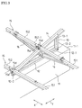
- FIG. 1 is a perspective view showing a photovoltaic power generation system to which a solar cell module rack according to an embodiment of the present invention is applied.
- FIG. 2 is a back view showing the photovoltaic power generation system of FIG. 1 .
- FIG. 3 is a partially enlarged perspective view showing the photovoltaic power generation system of FIG. 1 .
- the photovoltaic power generation system is assumed to be used to provide a power plant.
- a large number of solar cell modules are installed using the solar cell module rack of this embodiment.
- the solar cell module rack of this embodiment includes a plurality of concrete foundations 11 that are equally spaced and arranged on the ground.
- Base cross-pieces 12 are fixed to respective corresponding upper surfaces 11-1 of the concrete foundations 11, and are equally spaced and arranged side by side.
- Arms 13 are connected in an upright position to respective corresponding rear end portions 12-1 of the base cross-pieces 12.
- Vertical cross-pieces 14 are fixed to respective corresponding front end portions 12-2 of the base cross-pieces 12 and respective corresponding upper end portions 13-1 of the arms 13, spanning or extending diagonally therebetween.
- Three horizontal cross-pieces 15 (151, 152) are provided and arranged side by side on the vertical cross-pieces 14, intersecting the vertical cross-pieces 14 at right angles.
- Two trusses 16 are provided for each of the even-numbered base cross-pieces 12 as counted from the rightmost base cross-piece 12 (the first base cross-piece 12) in FIG. 1 .
- the trusses 16 span or extend between the base cross-piece 12 and the middle horizontal cross-piece 15.
- a truss structure that reinforces the middle horizontal cross-piece 15 is constructed.
- a direction in which the concrete foundations 11 are arranged side by side is referred to as an X direction (a left-right direction), and a direction perpendicular to the X direction is referred to as a Y direction (a front-back direction).
- a plurality of solar cell modules 17 are arranged in a line in the lateral direction and mounted on the upper horizontal cross-piece 15 and the middle horizontal cross-piece 15. Also, a plurality of solar cell modules 17 are arranged in a line in the lateral direction and mounted on the lower horizontal cross-piece 15 and the middle horizontal cross-piece 15. Therefore, the two lines of solar cell modules 17 are arranged side by side on the three horizontal cross-pieces 15. Six solar cell modules 17 are provided between any two vertical cross-pieces 14 that are adjacent to each other in the left-right direction. Each solar cell module 17 includes a solar cell panel 18 including a plurality of solar cells arranged in a matrix, and a frame member 19 holding the solar cell panel 18.
- Each concrete foundation 11 is produced by forming a formwork on the ground, pouring concrete into the formwork, and hardening the concrete.
- the concrete foundations 11 are equally spaced and arranged.
- the upper surfaces 11-1 of the concrete foundations 11 have the same height, i.e., are on the same horizontal plane.
- the upper surfaces 11-1 of the concrete foundations 11 are used as a horizontal foundation surface.
- the base cross-pieces 12 are equally spaced and arranged in parallel on and fixed to the foundation surface.
- the base cross-pieces 12, the arms 13, the vertical cross-pieces 14, the horizontal cross-pieces 15, the trusses 16, etc. are assembled and connected together into the solar cell module rack.
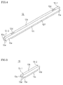
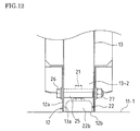
- FIG. 4 is a perspective view showing the base cross-piece 12.
- the base cross-piece 12 includes a pair of side plates 12a facing each other, a main plate 12b linking sides facing each other of the side plates 12a, and brims 12c each of which is formed by bending an edge of the corresponding side plate 12a outward, and thus, has a hat-shaped cross-section.
- Each brim 12c is cut away at the front end portion 12-2 of the base cross-piece 12.
- the front end portion 12-2 of the base cross-piece 12 has a U-shaped cross-section including the side plates 12a and the main plate 12b.
- An elongated hole 12d is formed in the vicinity of each of both ends of the main plate 12b of the base cross-piece 12.
- a perforated hole 12e is formed at each of both end portions of each side plate 12a.
- a perforated hole 12f is formed at each of middle portions of the brims 12c.
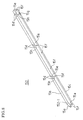
- FIG. 5 is a perspective view showing the arm 13.
- the arm 13 includes a pair of side plates 13a facing each other, a main plate 13b linking sides facing each other of the side plates 13a, and brims 13c each of which is formed by bending an edge of the corresponding side plate 13a outward, and thus, has a hat-shaped cross-section.
- the main plate 13b and the brims 13c are cut away, leaving only the side plates 13a.
- the main plate 13b and the brims 13c are cut away, leaving only the side plates 13a.
- a perforated hole 13d is formed at each of both end portions of each side plate 13a of the arm 13.
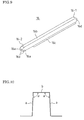
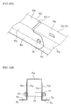
- FIGS. 6A and 6B are a perspective view and a plan view, respectively, showing the vertical cross-piece 14.
- the vertical cross-piece 14 includes a pair of side plates 14a facing each other, a main plate 14b linking sides facing each other of the side plates 14a, and brims 14c each of which is formed by bending an edge of the corresponding side plate 14a outward, and thus, has a hat-shaped cross-section.
- a pair of T-shaped holes 14d are formed in the vicinity of each of both ends and at a middle of the main plate 14b of the vertical cross-piece 14.
- a perforated hole 14e is formed at a front end portion of each side plate 14a.
- a perforated hole 14e is also formed at a portion of each side plate 14a that is closer to a rear end portion than a middle portion of the side plate 14a is.
- FIGS. 7A , 7B , and 8 show a cross-piece member included in the horizontal cross-piece 15.
- the horizontal cross-piece 15 is considerably long in the X direction, and therefore, it is almost impossible to form the horizontal cross-piece 15 using a single member. Therefore, the horizontal cross-piece 15 is formed by connecting a plurality of cross-piece members together.
- FIGS. 7A and 7B are a perspective view and a plan view, respectively, showing the rightmost (first) cross-piece member 151 of the horizontal cross-piece 15 in FIG. 1 .
- the first cross-piece member 151 includes a pair of side plates 15a facing each other, a main plate 15b linking sides facing each other of the side plates 15a, and brims 15c each of which is formed by bending an edge of the corresponding side plate 15a outward, and thus, has a hat-shaped cross-section.
- a pair of slits 15d and a perforated hole 15e are formed at each of four points of the main plate 15b of the cross-piece member 151.
- a perforated hole 15f and an engagement hole 15h are formed at each of a plurality of points of each side plate 15a.
- An elongated hole 15g is formed at each of both end portions of each brim 15c.
- the cross-piece member 151 is slightly longer than a space between each vertical cross-piece 14 of FIG. 1 . As a result, the cross-piece member 151 can be supported by the adjacent vertical cross-pieces 14, spanning or extending therebetween.
- FIG. 8 is a perspective view showing the second cross-piece member 152, or one of the subsequent cross-piece members 152, to the left of the rightmost (first) cross-piece member 151 of FIG. 1 .
- the second and subsequent cross-piece members 152 also each include a pair of side plates 15a, a main plate 15b, and brims 15c, and thus, has a hat-shaped cross-section.
- a pair of slits 15d and a perforated hole 15e are formed at each of three points of the main plate 15b.
- a perforated hole 15f and an engagement hole 15h are formed at each of a plurality of points of each side plate 15a.
- An elongated hole 15g is formed at an end portion of each brim 15c.
- the main plate 15b and a portion of each side plate 15a along a side thereof are cut away, leaving only the side plates 15a and the brims 15c.
- the cross-piece member 152 is substantially as long as the space between each vertical cross-piece 14 of FIG. 1 , and is slightly shorter than the cross-piece member 151.
- FIG. 9 is a perspective view showing the truss 16.
- the truss 16 includes a pair of side plates 16a facing each other, a main plate 16b linking sides facing each other of the side plates 16a, and brims 16c each of which is formed by bending an edge of the corresponding side plate 16a outward, and thus, has a hat-shaped cross-section.
- the main plate 16b and the brims 16c are cut away, leaving only the side plates 16a. Also, at the other end portion 16-2 of the truss 16, the main plate 16b and the brims 16c are cut away, leaving only the side plates 16a.
- a perforated hole 16d is formed at each of both end portions of each side plate 16a of the truss 16.
- the base cross-piece 12, the arm 13, the vertical cross-piece 14, the horizontal cross-piece 15, and the truss 16 all include side plates, a main plate linking sides facing each other of the side plates, and brims each of which is formed by bending an edge of the corresponding side plate outward, and thus, has a hat-shaped cross-section. All the hat-shaped cross-sections have the same size. All of them are formed by cutting a plated steel plate having the same thickness, cutting or perforating the plated steel plate, and bending the plated steel plate.
- the hat-shaped cross-sections of the base cross-piece 12, the arm 13, the vertical cross-piece 14, the horizontal cross-piece 15, and the truss 16 have a shape that a bending angle a of each side plate "a" with respect to the main plate "b” is set so that a space between the side plates "a” becomes gradually wider in a direction away from the main plate "b.”
- the space between the side plates "a” is wide at the opening of the hat-shaped cross-section of the cross-piece, and is narrower at the main plate "b” than at the opening of the cross-piece. Therefore, this facilitates putting the side plates of a cross-piece end portion on top of another cross-piece end portion as described below.
- FIGS. 11A and 11B are a perspective view and a front view, respectively, showing the triangular structure formed of the base cross-piece 12, the arm 13, and the vertical cross-piece 14.
- the base cross-piece 12 is fixed to the upper surface 11-1 of the concrete foundation 11.
- the arm 13 is connected in an upright position to the rear end portion 12-1 of the base cross-piece 12.
- the vertical cross-piece 14 is fixed to the front end portion 12-2 of the base cross-piece 12 and the upper end portion 13-1 of the arm 13, spanning or extending diagonally therebetween.
- the triangular structure formed of the base cross-piece 12, the arm 13, and the vertical cross-piece 14 is constructed.
- Two bolts 21 are previously provided, protruding from the upper surface 11-1 of the concrete foundation 11.
- the bolts 21 are inserted through the respective corresponding elongated holes 12d of the main plate 12b of the base cross-piece 12 so that the base cross-piece 12 is mounted on the concrete foundation 11 with the main plate 12b of the base cross-piece 12 abutting the upper surface 11-1 of the concrete foundation 11.
- the base cross-piece 12 can be moved along the elongated holes 12d (the Y direction of FIG. 1 ), and therefore, the position in the Y direction of the base cross-piece 12 is adjusted by moving the base cross-piece 12 in the Y direction.
- the bolts 21 are each inserted through a hole of a corresponding one of two U-shaped reinforcement members 22, which are provided inside the base cross-piece 12. A nut is screwed and fastened to each bolt 21. As a result, the base cross-piece 12 is fixed to the upper surface 11-1 of the concrete foundation 11.
- the arm 13 is connected in an upright position to the rear end portion 12-1 of the base cross-piece 12.
- the main plate 13b and the brims 13c are cut away, leaving only the side plates 13a.
- the space between the side plates 12a of the base cross-piece 12 becomes gradually wider toward the opening of the hat-shaped cross-section. Therefore, the lower end portions of the side plates 13a can be easily inserted and sandwiched between the rear end portions of the side plates 12a of the base cross-piece 12 while being are elastically deformed to approach each other. Therefore, the lower end portions of the side plates 13a and the rear end portions of the side plates 12a can be put on top of each other. In this case, the arm 13 is in an upright position without a support. This facilitates subsequently connecting the arm 13.
- a pipe 25 is inserted between the side plates 13a of the arm 13.
- the pipe 25, the perforated holes 13d of the side plates 13a of the arm 13, and the perforated holes 12e of the side plates 12a of the base cross-piece 12 are positioned and aligned.
- a bolt 26 is inserted through the pipe 25, the perforated holes 13d of the side plates 13a of the arm 13, the perforated holes 12e of the side plates 12a of the base cross-piece 12, and a washer.
- a nut 27 is screwed and fastened to an end of the bolt 26, whereby the lower end portions of the side plates 13a of the arm 13 are connected to the respective corresponding side plates 12a of the base cross-piece 12.
- the vertical cross-piece 14 is fixed to the front end portion 12-2 of the base cross-piece 12 and the upper end portion 13-1 of the arm 13, spanning or extending diagonally therebetween.
- the brims 12c are cut away at the front end portion of the base cross-piece 12.
- the space between the side plates 14a of the vertical cross-piece 14 becomes gradually wider toward the opening of the hat-shaped cross-section. Therefore, the front end portions of the side plates 12a of the base cross-piece 12 can be easily inserted between the front end portions of the side plates 14a of the vertical cross-piece 14 while being elastically deformed to approach each other. Therefore, the front end portions of the side plates 12a and the front end portions of the side plates 14a can be put on top of each other.
- a pipe is inserted between the side plates 12a of the base cross-piece 12.
- the pipe, the perforated holes 12e of the side plates 12a of the base cross-piece 12, and the perforated holes 14e of the side plates 14a of the vertical cross-piece 14 are positioned and aligned.
- a bolt is inserted through the pipe, the perforated holes 12e of the side plates 12a of the base cross-piece 12, the perforated holes 14e of the side plates 14a of the vertical cross-piece 14, and a washer.
- a nut is screwed and fastened to an end of the bolt, whereby the front end portions of the side plates 14a of the vertical cross-piece 14 are connected to the respective corresponding side plates 12a of the base cross-piece 12.
- the main plate 13b and the brims 13c are cut away, leaving only the side plates 13a. Therefore, the upper end portions of the side plates 13a can be easily inserted between the side plates 14a of the vertical cross-piece 14 while being elastically deformed to approach each other.
- a pipe is inserted across between the side plates 13a of the arm 13.
- a bolt is inserted through the pipe, the perforated holes 13d of the side plates 13a of the arm 13, the perforated holes 14e of the side plates 14a of the vertical cross-piece 14, and a washer.
- a nut is screwed and fastened to an end of the bolt, whereby the upper end portion 13-1 of the arm 13 is connected to the side plates 14a of the vertical cross-piece 14.
- a triangular structure formed of the base cross-piece 12, the arm 13, and the vertical cross-piece 14 is constructed.
- the triangular structure can sufficiently withstand forces in vertical and horizontal directions without significantly increasing the number of parts.
- FIG. 13 is a perspective view showing an attachment member 31 for connecting and fixing the cross-piece member 151, 152 of the horizontal cross-piece 15 to the vertical cross-piece 14.
- the attachment member 31 includes a bottom plate 31a having two screw holes 31b.
- the attachment member 31 includes a side plate 31c on each of left and right sides of the bottom plate 31a.
- the attachment member 31 also includes a side plate 31d on each of the front and rear sides of the bottom plate 31a.
- the side plates 31d are each folded into two portions.
- the attachment member 31 also includes T-shaped support strips 31e each of which protrudes from a middle of the corresponding side plate 31d.
- a pair of T-shaped holes 14d are formed in the vicinity of both ends and at a middle of the main plate 14b of the vertical cross-piece 14.
- the attachment member 31 is attached to the main plate 14b of the vertical cross-piece 14.
- the attachment member 31 is provided at each of the three points, i.e., at the middle and in the vicinity of both ends of the main plate 14b of the vertical cross-piece 14.
- each support strip 31e of the attachment member 31 is inserted into a slit 14f of the corresponding T-shaped hole 14d.
- Each support strip 31e is moved to an engagement hole 14g of the corresponding T-shaped hole 14d, and the head portion of each support strip 31e is hooked to the engagement hole 14g of the corresponding T-shaped hole 14d.
- the attachment member 31 is attached to the main plate 14b of the vertical cross-piece 14.
- the cross-piece member 151, 152 is put on the main plate 14b of the vertical cross-piece 14, intersecting the vertical cross-piece 14 at right angles.
- the brims 15c of the cross-piece member 151, 152 are arranged between the head portions of the support strip 31e of the attachment member 31.
- the elongated holes 15g of the brims 15c of the cross-piece member 151, 152 are positioned directly above the respective corresponding screw holes 31b of the attachment member 31 with the respective corresponding T-shaped holes 14d of the main plate 14b of the vertical cross-piece 14 being interposed between the elongated holes 15g and the respective corresponding screw holes 31b.
- Bolts 32 are screwed and loosely fastened through the respective corresponding elongated holes 15g of the brims 15c of the cross-piece member 151, 152 and the respective corresponding T-shaped holes 14d of the main plate 14b of the vertical cross-piece 14 into the respective corresponding screw holes 31b of the attachment member 31.
- the bolts 32 can be moved along the respective corresponding elongated holes 15g of the brims 15c of the cross-piece member 151, 152. Therefore, the cross-piece member 151, 152 is moved along the elongated holes 15g (in the X direction of FIG. 1 ) so that a position in the X direction of the cross-piece member 151, 152 is adjusted.
- the attachment member 31 can also be moved along the T-shaped holes 14d of the main plate 14b of the vertical cross-piece 14 (in a longitudinal direction of the vertical cross-piece 14).
- the cross-piece member 151, 152 can also be moved along with the attachment member 31. By the movement of the cross-piece member 151, 152 in the longitudinal direction of the vertical cross-piece 14, the spaces between the three horizontal cross-pieces 15 provided on the vertical cross-piece 14 are adjusted.
- connection structure of a plurality of the cross-piece members 151, 152 included in the horizontal cross-piece 15 will be described.
- the cross-piece member 151 of FIGS. 7A and 7B is the rightmost (first) cross-piece member of the horizontal cross-piece 15 of FIG. 1 .
- the cross-piece member 151 is supported by the vertical cross-pieces 14 provided on the first and second concrete foundations 11 of FIG. 1 , spanning or extending therebetween.
- the cross-piece member 151 is fixed to the vertical cross-pieces 14 using the attachment members 31.
- the cross-piece member 152 of FIG. 8 is the second cross-piece member, or one of the subsequent cross-piece members 152, of the horizontal cross-piece 15 of FIG. 1 .
- the cross-piece member 152 is supported by the left end portion of the immediately preceding cross-piece member and the succeeding vertical cross-piece 14, spanning or extending therebetween.
- the second cross-piece member 152 is supported by the left end portion of the first cross-piece member 151 and the third vertical cross-piece 14, spanning or extending therebetween.
- the third cross-piece member 152 is supported by the left end portion of the second cross-piece member 152 and the fourth vertical cross-piece 14, spanning or extending therebetween.
- n-th cross-piece member 152 is supported by the left end portion of the (n - 1)th cross-piece member 152 and the (n + 1)th vertical cross-piece 14, spanning or extending therebetween.
- the second and subsequent cross-piece members 152 are also connected to the respective corresponding vertical cross-pieces 14 using the attachment members 31.
- the main plate 15b is not cut away at either of both ends of the first cross-piece member 151.
- FIG. 8 at the one end portions 152-1 of the second and subsequent cross-piece members 152, portions along a side of the main plate 15b and the side plates 15a are cut away, leaving only the side plates 15a and the brims 15c. Thereafter, as shown in FIGS. 1 and 3 , the one end portion 152-1 of each of the second and subsequent cross-piece members 152 is connected to the left end portion of the immediately preceding cross-piece member.
- the left end portions of the side plates 15a of the first cross-piece member 151 are inserted and sandwiched between the one end portions of the side plates 15a of the second cross-piece member 152.
- the space between the side plates 15a becomes gradually wider toward the opening of the hat-shaped cross-section of the horizontal cross-piece 15 (the cross-piece member 151, 152).
- a pipe 25 is inserted across between the side plates 15a of the first cross-piece member 151.
- a bolt 26 is inserted through the pipe 25, the perforated holes 15f of the side plates 15a of the first cross-piece member 151, the perforated holes 15f of the side plates 15a of the second cross-piece member 152, and a washer.
- a nut 27 is screwed and fastened to an end of the bolt 26, whereby the side plates 15a of the second cross-piece member 152 are connected to the respective corresponding side plates 15a of the first cross-piece member 151.
- the one end portions of the side plates 15a of the third cross-piece member 152 are put on top of the left end portions of the side plates 15a of the second cross-piece member 152, so that the left end portions of the side plates 15a of the second cross-piece member 152 are inserted and sandwiched between the one end portions of the side plates 15a of the third cross-piece member 152. Thereafter, the side plates 15a of the third cross-piece member 152 are connected to the side plates 15a of the second cross-piece member 152 using a pipe 25, a bolt 26, a nut 27, and a washer.
- the left end portions of the side plates 15a of the (n - 1)th cross-piece member 152 are inserted and sandwiched between the one end portions of the side plate 15a of the n-th cross-piece member 152.
- the side plates 15a of the n-th cross-piece member 152 are connected to the side plates 15a of the (n - 1)th cross-piece member 152 using a pipe 25, a bolt 26, a nut 27, and a washer.
- the single long horizontal cross-piece 15 is formed by connecting the cross-piece members 151 and 152 together.
- FIGS. 17 and 18 are a front view and a side view, respectively, showing the trusses 16 spanning or extending between the base cross-piece 12 and the middle horizontal cross-piece 15.
- the trusses 16 are arranged perpendicular to the solar cell module 17.
- side plates 31b of a connection member 31 for connecting the base cross-piece 12 and the two trusses 16 together are inclined.
- FIGS. 19A and 19B are a perspective view and a side view, respectively, showing the connection member 31 for connecting the base cross-piece 12 and the two trusses 16 together.
- the connection member 31 includes a bottom plate 31a, and side plates 31b that are bent at both edges of the bottom plate 31a.
- the side plates 31b are inclined with respect to the bottom plate 31a.
- Two elongated holes 31c are formed in the bottom plate 31a.
- a perforated hole 31d and a screw hole 31e are formed in the respective corresponding side plates 31b.
- the bottom plate 31a of the connection member 31 is placed at substantially a middle of the brims 12c of the even-numbered base cross-piece 12 with the two elongated holes 31c of the bottom plate 31a coinciding with the respective corresponding perforated holes 12f of the brims 12c.
- Two bolts are inserted through the respective corresponding elongated holes 31c of the bottom plate 31a and the respective corresponding perforated holes 12f of the brims 12c. Nuts are screwed onto one ends of the respective corresponding bolts, whereby the connection member 31 is loosely fastened to the brims 12c of the base cross-piece 12.
- connection member 31 In the loosely fastened state, the bolts are inserted through the respective corresponding elongated holes 31c of the bottom plate 31a of the connection member 31. Therefore, the connection member 31 can be moved along the elongated holes 31c (in the X direction of FIG. 1 ).
- both end portions of the two trusses 16 are connected to the connection member 31 and the middle horizontal cross-piece 15.
- the end portions (the one end portions 16-1 of FIG. 9 ) of the side plates 16a of the two trusses 16 are alternately put on top of each other.
- a pipe is inserted between the innermost side plates facing each other.
- a bolt is inserted through the pipe, the perforated holes 16d of the side plates 16a of the two trusses 16, the perforated hole 31d of the side plate 31b of the connection member 31, and a washer.
- An end of the bolt is screwed into the screw hole 31e of the side plate 31b of the connection member 31, whereby the end portions of the two trusses 16 are loosely fastened to the connection member 31.
- the end portions (the other end portions 16-2 of FIG. 9 ) of the side plates 16a of the truss 16 are inserted between the side plates 15a of the cross-piece member 151 or 152 of the middle horizontal cross-piece 15 while being elastically deformed to approach each other.
- a pipe is inserted between the side plates 16a of the truss 16.
- a bolt is inserted through the pipe, the perforated holes 16d of the side plates 16a of the truss 16, the perforated holes 15f of the side plates 15a of the cross-piece member 151 or 152, and a washer.
- a nut is screwed onto an end of the bolt, whereby the end portions of each truss 16 are loosely fastened to the cross-piece member 151 or 152.
- each truss 16 After both end portions of each truss 16 are thus connected to the connection member 31 and the middle horizontal cross-piece 15, the bolts for connecting both end portions of the truss 16 are further fastened to fix the truss 16.
- the middle horizontal cross-piece 15 supports end portions of the upper and lower solar cell modules 17.
- the upper and lower horizontal cross-pieces 15 support end portions of the upper and lower solar cell modules 17, respectively. Therefore, the structure for attaching the solar cell module 17 differs between the middle horizontal cross-piece 15 and the upper and lower horizontal cross-pieces 15. These different attachment structures will be separately described.
- FIGS. 20A, 20B , and 20C are a front view showing a first connection member provided on the middle horizontal cross-piece 15 on the rear side of the solar cell module 17, and perspective views of the first connection member as viewed from the front and the rear, respectively.
- the first connection member 41 includes a side plate 41a, a top plate 41b that is formed by bending an upper edge of the side plate 41a, and a bottom plate 41g that is formed by bending a lower edge of the side plate 41a.
- the top plate 41b includes a hanging strip 41e that is formed by bending a center portion of a side of the top plate 41b, hanging from the remainder of the top plate 41b, and protrusion strips 41f that are formed by bending both end portions of the side of the top plate 41b into an upright position.
- a screw hole 41d is formed at substantially a middle of the top plate 41b.
- a perforated hole 41c is formed in the side plate 41a.
- An elongated hole 41i is formed in the bottom plate 41g.
- a U-shaped cut is formed in the side plate 41a of the first connection member 41 above the perforated hole 41c. A portion inside the U-shape cut is pushed from the side plate 41a in a direction opposite to the bottom plate 41g and the top plate 41b, to form a nail portion 41h.
- the height from the lower surface of the bottom plate 41g of the first connection member 41 to the upper surface of the top plate 41b is slightly higher than the height from the upper surface of the brim 15c of the middle horizontal cross-piece 15 to the upper surface of the main plate 15b.
- FIGS. 21A-21C are a perspective view showing a first fixing member provided on a light reception side of the solar cell module 17 as viewed from the top, a side view thereof, and a perspective view thereof as viewed from below, respectively.
- the first fixing member 43 includes an abutment plate (abutment portion) 43a that abuts the frame member 19 of the solar cell module 17.
- the first fixing member 43 also includes protrusion strips 43b that are formed by bending a front and a rear end portion of the abutment plate 43a downward.
- the first fixing member 43 also includes a through hole 43c formed at a middle portion of the abutment plate 43a.
- FIGS. 22A and 22B are a perspective view showing a second fixing member provided on a light reception side of the solar cell module 17 as viewed from the top, and a side view thereof.
- the second fixing member 44 includes an abutment plate (abutment portion) 44a that abuts the frame member 19 of the solar cell module 17.
- the second fixing member 44 also includes protrusion strips 44b that are formed by bending a front and a rear end portion of the abutment plate 44a downward.
- the second fixing member 44 also includes a through hole 44c formed at a middle portion of the abutment plate 44a.
- the second fixing member 44 also includes an upright wall 44d that is formed by bending an edge of the abutment plate 44a perpendicularly.
- the second fixing member 44 also includes a bottom strip 44e that is formed by bending a lower edge of the upright wall 44d.
- the first connection member 41, the first fixing member 43, and the second fixing member 44 are all formed of a steel plate much thicker than those of the base cross-piece 12, the arm 13, the vertical cross-piece 14, the horizontal cross-piece 15, and the truss 16, and therefore, have high strength.
- a set of two first connection members 41 is provided at each of portions where pairs of the slits 15d are formed, of the main plate 15b of the cross-piece member 151, 152 of the middle horizontal cross-piece 15.
- the side plates 41a of the two first connection members 41 are put on top of the respective corresponding side plates 15a of the horizontal cross-piece 15.
- the top plate 41b and the bottom plate 41g of each first connection member 41 are arranged to protrude outward from the horizontal cross-piece 15.
- the upper surface of the top plate 41b of the first connection member 41 is slightly higher than the upper surface of the main plate 15b of the horizontal cross-piece 15.
- the nail portion 41h of the side plate 41a of each first connection member 41 is engaged with the engagement hole 15h of the corresponding side plate 15a of the horizontal cross-piece 15, whereby the first connection member 41 is loosely fastened to the side plate 15a of the horizontal cross-piece 15.
- a pipe 72 is inserted between the side plates 15a of the horizontal cross-piece 15.
- a bolt 73 is inserted through the pipe 72, the perforated holes 15f of the side plates 15a of the horizontal cross-piece 15, the perforated holes 41c of the side plates 41a of the first connection members 41, and a washer.
- a nut 74 is screwed and fastened to an end of the bolt 73, whereby the first connection members 41 are fixed to the horizontal cross-piece 15.
- the elongated holes 41i of the bottom plates 41g of the first connection members 41 coincide with the respective corresponding elongated holes 15g of the brims 15c of the cross-piece member 151. Also at the one end portion of the cross-piece member 152 of FIG. 8 , the elongated holes 41i of the bottom plates 41g of the first connection members 41 coincide with the respective corresponding elongated holes 15g of the brims 15c of the cross-piece member 152.
- the elongated holes 15g of the brims 15c of each of the cross-piece members 151, 152 are not covered by the bottom plates 41g of the first connection member 41, and the length of the elongated holes 15g are not limited, and therefore, each of the cross-piece members 151, 152 is not prevented from moving along the elongated holes 15g.
- FIG. 24A is a plan view showing a state in which four (upper, lower, left, and right) solar cell modules 17 are attached to the middle horizontal cross-piece 15 using the first connection members 41 and the first fixing members 43.
- FIG. 24B is a cross-sectional view taken along line B-B of FIG. 24A .
- FIG. 24C is a cross-sectional view taken along line C-C of FIG. 24A .
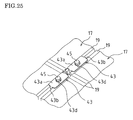
- FIG. 25 is a perspective view showing the state of FIGS. 24A-24C as viewed from the light reception side of the solar cell module.
- the frame members 19 of the lower left and right solar cell modules 17 are inserted between the protrusion strips 41f of the lower first connection member 41 and thus mounted on the main plate 15b of the horizontal cross-piece 15.
- the solar cell modules 17 are slid down on the main plate 15b of the horizontal cross-piece 15 until inner edges 19a of the frame members 19 of the lower left and right solar cell modules 17 abut the protrusion strips 41f of the lower first connection member 41, whereby the up-down positions of the solar cell modules 17 are determined.
- the protrusion strips 43b of the first fixing member 43 are inserted between the frame members 19 of the lower left and right solar cell modules 17, whereby the frame members 19 of the solar cell modules 17 are spaced apart by a predetermined distance.
- bottom protrusion portions 19b of the frame members 19 of the solar cell modules 17 abut the protrusion strips 41f of the first connection member 41. As a result, the left-right positions of the solar cell modules 17 are determined.
- a bolt 45 is screwed and fastened to the screw hole 41d of the top plate 41b of the first connection member 41 through the through hole 43c of the first fixing member 43 and a gap between the frame members 19 of the lower left and right solar cell modules 17.
- the frame members 19 of the lower left and right solar cell modules 17 are sandwiched and fixed between the first fixing member 43 and the main plate 15b of the horizontal cross-piece 15.
- the frame members 19 of the upper left and right solar cell modules 17 are inserted between the protrusion strips 41f of the upper first connection member 41 and thus mounted on the main plate 15b of the horizontal cross-piece 15.
- the up-down positions of the upper left and right solar cell modules 17 are determined by causing the frame members 19 of the upper left and right solar cell modules 17 to abut the frame members 19 of the lower left and right solar cell modules 17.
- the protrusion strips 43b of the first fixing member 43 are inserted between the frame members 19 of the upper left and right solar cell modules 17.
- the bottom protrusion portions 19b of the frame members 19 of the solar cell modules 17 abut the protrusion strips 41f of the first connection member 41.
- the left-right positions of the solar cell modules 17 are determined.
- a bolt 45 is screwed and fastened to the screw hole 41d of the top plate 41b of the first connection member 41 through the through hole 43c of the first fixing member 43 and a gap between the frame members 19 of the upper left and right solar cell modules 17.
- the frame members 19 of the upper left and right solar cell modules 17 are fixed.
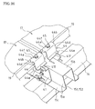
- the second fixing members 44 are used to fix two (upper and lower) rightmost or leftmost solar cell modules 17 of FIG. 1 .
- the rightmost or leftmost solar cell modules 17 are mounted on the main plate 15b of the horizontal cross-piece 15 with the frame members 19 thereof being inserted between the protrusion strips 41f of the first connection members 41. Thereafter, the bottom strips 44e of the second fixing members 44 are put on the main plate 15b of the horizontal cross-piece 15. The protrusion strips 44b of the second fixing members 44 are pressed against the frame members 19 of the solar cell modules 17. The bottom protrusion portions 19b of the frame members 19 of the solar cell modules 17 abut the protrusion strips 41f of the first connection members 41. As a result, the left-right positions of the solar cell modules 17 are determined.
- bolts 45 are screwed and fastened to the respective corresponding screw holes 41d of the top plates 41b of the first connection members 41 through the respective corresponding through holes 44c of the second fixing members 44.
- the frame members 19 of the solar cell modules 17 are sandwiched and fixed between the second fixing members 44 and the main plate 15b of the horizontal cross-piece 15.
- FIG. 27A is a perspective view showing a second connection member provided on the upper and lower horizontal cross-pieces 15 on the rear side of the solar cell module 17.
- FIGS. 27B and 27C are a plan view and a side view, respectively, showing the second connection member of FIG. 27A .
- the second connection member 51 includes a pair of side plates 51a facing each other, a top plate 51b linking sides facing each other of the side plates 51a, and brims 51c each of which is formed by bending an edge of the corresponding side plate 51a, protruding outward, and therefore, has a hat-shaped cross-section.
- the second connection member 51 is shaped and sized to fit into the inside of the horizontal cross-piece 15.
- L-shaped cuts extending inward from both ends of the top plate 51b of the second connection member 51 are formed.
- the plates inside the L-shaped cuts are raised to an upright position to form protrusion portions 51f.
- a screw hole 51d is formed in each of the side plates 51a of the second connection member 51.
- a screw hole 51e is formed on a center line of the top plate 51b.
- An elongated hole 51g is formed in each brim 51c.
- the second connection member 51 is also formed of a sufficiently thick steel plate, and therefore, has high strength, similar to the first connection member 41, the first fixing member 43, and the second fixing member 44.
- the second connection member 51 is provided at each portion where a pair of slits 15d and a perforated hole 15e are formed, of the main plates 15b of the upper and lower horizontal cross-pieces 15, and is fitted into the inside of the horizontal cross-piece 15.
- the side plates 15a of the horizontal cross-piece 15 are put on top of the respective corresponding side plates 51a of the second connection member 51.
- the main plate 15b of the horizontal cross-piece 15 is put on top of the top plate 51b of the second connection member 51.
- the brims 15c of the horizontal cross-piece 15 are put on top of the respective corresponding brims 51c of the second connection member 51.
- the main plate, the side plate, and the brim have a two-layer structure at points where the second connection member 51 is provided, and therefore, the strength is high at the points.
- the elongated holes 51g of the brims 51c of the second connection member 51 coincide with the respective corresponding elongated holes 15g of the brims 15c of the cross-piece member 151. Also, at the one end portion of the cross-piece member 152 of FIG. 8 , the elongated holes 51g of the brims 51c of the second connection member 51 coincide with the respective corresponding elongated holes 15g of the brims 15c of the cross-piece member 152.
- the elongated holes 15g of the brims 15c of each of the cross-piece members 151, 152 are not covered by the brims 51c of the second connection member 51, and the length of the elongated holes 15g are not limited, and therefore, each of the cross-piece members 151, 152 is not prevented from moving along the elongated holes 15g.
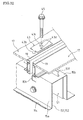
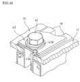
- FIG. 29A is a plan view showing a state in which two (left and right) solar cell modules 17 are attached to the upper and lower horizontal cross-pieces 15 using the second connection member 51 and the first fixing member 43.
- FIG. 29B is a cross-sectional view taken along line B-B of FIG. 29A .
- FIG. 29C is a cross-sectional view taken along line C-C of FIG. 29A .
- the frame members 19 of the left and right solar cell modules 17 are inserted between the protrusion strips 51f of the second connection member 51 and thus mounted on the main plate 15b of the horizontal cross-piece 15. Thereafter, the protrusion strips 43b of the first fixing member 43 are inserted between the frame members 19 of the left and right solar cell modules 17, whereby the frame members 19 of the solar cell modules 17 are spaced apart by a predetermined distance. At the same time, the bottom protrusion portions 19b of the frame members 19 of the solar cell modules 17 abut the protrusion strips 51f of the second connection member 51. As a result, the left-right positions of the solar cell modules 17 are determined.
- a bolt 45 is inserted and fastened through the through hole 43c of the first fixing member 43, a gap between the frame members 19 of the solar cell modules 17, and the perforated hole 15e of the main plate 15b of the horizontal cross-piece 15 into the screw hole 51e of the top plate 51b of the second connection member 51.
- the frame members 19 of the solar cell modules 17 are sandwiched and fixed between the first fixing member 43 and the main plate 15b of the horizontal cross-piece 15.
- the second fixing member 44 is also used to fix two (upper and lower) rightmost or leftmost solar cell modules 17 of FIG. 1 .
- the rightmost or leftmost solar cell module 17 is mounted on the main plate 15b of the horizontal cross-piece 15 with the frame member 19 thereof being inserted between the protrusion portions 51f of the second connection member 51.
- the bottom strips 44e of the second fixing member 44 are put on the main plate 15b of the horizontal cross-piece 15.
- the protrusion strips 44b of the second fixing member 44 are pressed against the frame member 19 of the solar cell module 17.
- the bottom protrusion portion 19b of the frame member 19 of the solar cell module 17 abuts the protrusion portion 51f of the second connection member 51.
- the left-right position of the solar cell module 17 is determined.
- a bolt 45 is screwed and fastened through the through hole 44c of the second fixing member 44 and the perforated hole 15e of the main plate 15b of the horizontal cross-piece 15 into the screw hole 51e of the top plate 51b of the second connection member 51.
- the frame member 19 of the solar cell module 17 is sandwiched and fixed between the second fixing member 44 and the main plate 15b of the horizontal cross-piece 15.
- the solar cell module rack of this embodiment a large number of solar cell modules 17 are mounted. If the solar cell modules 17 are separately connected to the ground using a wire or the like, the connecting work is troublesome.
- the solar cell module rack of this embodiment only the middle horizontal cross-piece 15 is connected to the ground using a wire or the like.
- Each solar cell module 17 is attached and fixed to the middle horizontal cross-piece 15 while conduction is established between the solar cell module 17 and the middle horizontal cross-piece 15 via the first fixing member 43 and the second fixing member 44, whereby the solar cell module 17 is grounded. Therefore, the solar cell modules 17 are grounded by only the work of connecting the middle horizontal cross-piece 15 to the ground using a wire or the like.
- the abutment plate 43a of the first fixing member 43 has two perforated holes 43d in addition to the through hole 43c.
- the perforated holes 43d are formed in the vicinity of the through hole 43c on both sides of a virtual line extending through centers of the protrusion strips 43b and the through hole 43c. Therefore, as shown in FIGS. 24A-24C or FIGS. 29A-29C , when the first fixing member 43 is put on the frame members 19 of the left and right solar cell modules 17 with the protrusion strips 43b thereof being inserted between the frame members 19, the perforated holes 43d are located directly above the respective corresponding frame members 19.
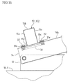
- Each perforated hole 43d has a ring-shaped protrusion 43e having a sharp tip along an entire inner circumferential edge of the perforated hole 43d.
- the abutment plate (abutment portion) 43a has the ring-shaped protrusion 43e formed along the circumferential edge of the perforated hole 43d.
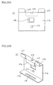
- the ring-shaped protrusion 43e with a sharp tip along the circumferential edge of the perforated hole 43d is formed as follows. For example, as shown in FIGS. 31A and 31B , the perforated hole 43d is formed in the abutment plate 43a of the first fixing member 43 using a drill etc.
- a pin 61 having an outer diameter slightly larger than the inner diameter of the perforated hole 43d is struck against the inner circumferential edge of the perforated hole 43d with great force, whereby the entire inner circumferential edge of the perforated hole 43d on a side opposite to the pin 61 is caused to protrude.
- a bolt (fastening member) 45 is screwed and fastened through the through hole 43c of the first fixing member (fixing member) 43 and a gap between the frame members 19 of the left and right solar cell modules 17 into the screw hole 41d of the top plate 41b of the first connection member 41, whereby the frame member 19 of the solar cell module 17 is sandwiched and fixed between the first fixing member 43 and the main plate 15b of the horizontal cross-piece (rack member) 15.
- a bolt (fastening member) 45 is screwed and fastened through the through hole 43c of the first fixing member (fixing member) 43 and a gap between the frame members 19 of the left and right solar cell modules 17 into the screw hole 41d of the top plate 41b of the first connection member 41, whereby the frame member 19 of the solar cell module 17 is sandwiched and fixed between the first fixing member 43 and the main plate 15b of the horizontal cross-piece (rack member) 15.
- the ring-shaped protrusions 43e with a sharp tip along the circumferential edges of the perforated holes 43d of the first fixing member 43 dig into the respective corresponding frame members 19 of the left and right solar cell modules 17, so that conduction is established between the first fixing member 43 and the frame members 19 of the left and right solar cell modules 17.
- a bolt 45 is screwed and fastened through the through hole 43c of the first fixing member 43 and a gap between the frame members 19 of the left and right solar cell modules 17 into the screw hole 51e of the top plate 51b of the second connection member 51, whereby the frame members 19 of the solar cell modules 17 are sandwiched and fixed between the first fixing member 43 and the main plate 15b of the horizontal cross-piece 15.
- the ring-shaped protrusions 43e with a sharp tip along the circumferential edges of the perforated holes 43d of the first fixing member 43 dig into the respective corresponding frame members 19 of the left and right solar cell modules 17, so that conduction is established between the first fixing member 43 and the frame members 19 of the left and right solar cell modules 17.
- the ring-shaped protrusions 43e of the perforated holes 43d of the first fixing member 43 are formed in the vicinity of the bolt 45. Therefore, the fastening force of the bolt 45 is reliably applied to the ring-shaped protrusions 43e of the perforated holes 43d, so that the ring-shaped protrusions 43e of the perforated holes 43d dig into the respective corresponding frame members 19 of the left and right solar cell modules 17, whereby conduction is established between the first fixing member 43 and the frame members 19 of the left and right solar cell modules 17.
- the frame member 19 of the solar cell module 17 is made of aluminum or aluminum alloy
- an insulating oxide film is formed on a surface of the aluminum or aluminum alloy.
- the frame member 19 of the solar cell module 17 is made of, for example, aluminum or aluminum alloy (metal material) covered with a surface oxide film (insulating oxide film) of the aluminum or aluminum alloy. Therefore, if the first fixing member 43 is only made in contact with the surface of the frame member 19, conduction is not established between the first fixing member 43 and the aluminum or aluminum alloy of the frame member 19.
- the ring-shaped protrusion 43e with a sharp tip along the circumferential edge of the perforated hole 43d of the first fixing member 43 digs into the frame member 19 of the solar cell module 17
- the ring-shaped protrusion 43e with a sharp tip along the circumferential edge of the perforated hole 43d of the first fixing member 43 breaks the insulating surface oxide film on the surface of the frame member 19 to abut the aluminum or aluminum alloy. Therefore, conduction is established between the first fixing member 43 and the aluminum or aluminum alloy of the frame member 19 of the solar cell module 17.
- the first fixing member 43, the first connection member 41 or the second connection member 51, the horizontal cross-piece 15, etc. are made of a conductive material (conductor) such as a plated steel plate or a steel plate etc.
- the bolt 45 is also made of a conductive material such as steel etc. These are firmly joined together. Therefore, when conduction is established between the first fixing member 43 and the frame member 19 of the solar cell module 17, conduction is also established between the frame member 19 of the solar cell module 17 and the horizontal cross-piece 15 via the first fixing member 43, the bolt 45, and the first connection member 41 or the second connection member 51.
- FIGS. 22A and 22B similar to the first fixing member 43, two perforated holes 44f are formed in the abutment plate 44a of the second fixing member 44 in addition to the through hole 44c.
- the two perforated holes 44f are formed at two points in the vicinity of the through hole 44c.
- FIG. 26 or 30 when the abutment plate 44a of the second fixing member 44 is put on the frame member 19 of the rightmost or leftmost solar cell module 17 with the protrusion strips 44b of the second fixing member 44 being pressed against the frame member 19 of the solar cell module 17, the perforated holes 44f are located directly above the frame member 19 of the solar cell module 17.
- Each perforated hole 44f of the second fixing member 44 has a ring-shaped protrusion 44g with a sharp tip along an entire inner circumferential edge of the perforated hole 44f.
- the abutment plate (abutment portion) 44a has the ring-shaped protrusion 44g formed along the circumferential edge of the perforated hole 44f.
- the ring-shaped protrusion 44g with a sharp tip along the circumferential edge of the perforated hole 44f is formed in a manner similar to that of the ring-shaped protrusion 43e with a sharp tip along the circumferential edge of the perforated hole 43d of the first fixing member 43.
- a bolt (fastening member) 45 is screwed and fastened through the through hole 44c of the second fixing member (fixing member) 44 into the screw hole 41d of the top plate 41b of the first connection member 41, whereby the frame member 19 of the solar cell module 17 is sandwiched and fixed between the second fixing member 44 and the main plate 15b of the horizontal cross-piece (rack member) 15.
- the ring-shaped protrusions 44g with a sharp tip along the circumferential edges of the perforated holes 44f of the second fixing member 44 dig into the frame member 19 of the solar cell module 17, so that conduction is established between the second fixing member 44 and the frame member 19 of the solar cell module 17.
- a bolt 45 is screwed and fastened through the through hole 44c of the second fixing member 44 into the screw hole 51e of the top plate 51b of the second connection member 51, whereby the frame member 19 of the solar cell module 17 is sandwiched and fixed between the second fixing member 44 and the main plate 15b of the horizontal cross-piece 15.
- the ring-shaped protrusions 44g with a sharp tip along the circumferential edges of the perforated holes 44f of the second fixing member 44 break the insulating oxide film of the frame member 19 to dig into the frame member 19, so that conduction is established between the second fixing member 44 and the frame member 19 of the solar cell module 17.
- the ring-shaped protrusions 44g of the perforated holes 44f of the second fixing member 44 are formed in the vicinity of the bolt 45. Therefore, the fastening force of the bolt 45 is reliably applied to the ring-shaped protrusions 44g of the perforated holes 44f, so that the ring-shaped protrusions 44g of the perforated holes 44f dig into the frame member 19 of the solar cell module 17, whereby conduction is established between the second fixing member 44 and the frame member 19 of the solar cell module 17.
- the second fixing member 44, the first connection member 41 or the second connection member 51, the horizontal cross-piece 15, etc. are made of a conductive material such as a plated steel plate or a steel plate etc.
- the bolt 45 is also made of a conductive material such as steel etc. These are firmly joined together. Therefore, when conduction is established between the second fixing member 44 and the frame member 19 of the solar cell module 17, conduction is also established between the frame member 19 of the solar cell module 17 and the horizontal cross-piece 15 via the second fixing member 44, the bolt 45, and the first connection member 41 or the second connection member 51.
- the ring-shaped protrusions 43e and 44g of the perforated holes 43d and 44f dig into the frame member 19 of the solar cell module 17, so that conduction is established between the first and second fixing members 43 and 44 and the frame member 19 of the solar cell module 17, and therefore, conduction is also established between the frame member 19 of the solar cell module 17 and the middle horizontal cross-piece 15.
- the solar cell module rack is formed by combining and joining a plurality of conductive cross-pieces, arms, trusses, etc., the entire solar cell module rack is grounded by grounding the middle horizontal cross-piece 15.
- the ring-shaped protrusions 43e and 44g of the perforated holes 43d and 44f of the first fixing member 43 and the second fixing member 44 are each in the shape of a ring formed along the entire inner circumferential edge of the perforated hole. Therefore, even if force that tries to cause the ring-shaped protrusion 43e, 44g to fall down is applied thereto in any direction, the force can be spread or distributed throughout the ring-shaped protrusion 43e, 44g, and the ring-shaped protrusion 43e, 44g has high strength against force in any direction.
- the first fixing member 43 is used to fix all the frame members 19 of the solar cell modules 17 to the middle horizontal cross-piece 15. Therefore, the ring-shaped protrusion 43e of the perforated hole 43d may be formed only in the first fixing member 43, and the ring-shaped protrusion 44g of the perforated hole 44f may not be formed in the second fixing member 44, and even in this case, conduction can be established between the frame member 19 of the solar cell module 17 and the middle horizontal cross-piece 15.
- the first fixing member 43 is used not only to fix all the frame members 19 of the solar cell modules 17 to the middle horizontal cross-piece 15, but also to fix the frame members 19 of the solar cell modules 17 to the upper and lower horizontal cross-pieces 15. Therefore, one or two of the upper, lower, and middle horizontal cross-pieces 15 may be selectively grounded.
- the numbers of the perforated holes 43d and 44f of the first fixing member 43 and the second fixing member 44 may be increased or decreased, depending on the number of points of the frame member 19 of the solar cell module 17 into which the ring-shaped protrusion 43e, 44f digs.
- the shape of the perforated hole 43d, 44f is not limited to a circle and may be an ellipse etc., and the size is also not limited. Typically, as the number of perforated holes increases or as the size of the perforated hole increases, conduction is more stably established between the frame member 19 of the solar cell module 17 and the solar cell module rack.
- the differences between diameters of the through holes 43c and 44c of the first fixing member 43 and the second fixing member 44 and a diameter of the bolt 45 are assumed to be the maximum values of the displacement widths of the first fixing member 43 and the second fixing member 44.
- the diameter of the perforated hole 43d, 44f is larger than the maximum value of the displacement width, even when the bolt 45 is refastened, the mark left by the previous digging of the ring-shaped protrusion 43e, 44g of the perforated hole 43d, 44f intersects or overlaps the mark formed by the current digging of the ring-shaped protrusion 43e, 44g after refastening, and therefore, conduction can be reliably maintained.
- the diameter of the through hole 43c, 44c is 11 mm and the diameter of the bolt 45 is 8 mm, the difference between these diameters is 3 mm, and therefore, in this case, the diameter of the perforated hole 43d, 44f is preferably 5 mm.
- the diameter of a perforated hole 71 of a fixing member through which the bolt 45 is inserted may be larger than the diameter of the screw hole of the bolt 45.
- a ring-shaped protrusion 71a with a sharp tip may be formed along an entire inner circumferential edge of the perforated hole 71.
- the ring-shaped protrusion 71a may abut the frame member of the solar cell module.
- the perforated holes 43d of the first fixing members 43 and the perforated holes 44f of the second fixing members 44 may be removed.
- the first fixing member 43 (or the second fixing member 44) having such a structure can be produced by joining a flat plate to a surface opposite to the surface of the abutment plate 43a (or the abutment plate 44a) abutting the frame member 19 of the solar cell module 17 so that the perforated hole 43d (or the perforated hole 44f) is covered.
- the number of solar cell modules fixed to the solar cell module rack is not particularly limited and may be one.
Landscapes
- Engineering & Computer Science (AREA)
- Chemical & Material Sciences (AREA)
- Thermal Sciences (AREA)
- General Engineering & Computer Science (AREA)
- Physics & Mathematics (AREA)
- Life Sciences & Earth Sciences (AREA)
- Sustainable Development (AREA)
- Sustainable Energy (AREA)
- Mechanical Engineering (AREA)
- Combustion & Propulsion (AREA)
- Architecture (AREA)
- Civil Engineering (AREA)
- Structural Engineering (AREA)
- Photovoltaic Devices (AREA)
- Roof Covering Using Slabs Or Stiff Sheets (AREA)
Abstract
A solar cell module rack for mounting a solar cell module (17) includes a first fixing member (43) mounted on and above a frame member (19) of the solar cell module (17), a horizontal cross-piece mounted on and below the frame member (19) of the solar cell module (17), and a bolt (45) configured to fasten the first fixing member (43) and the horizontal cross-piece together so that the first fixing member (43) and the horizontal cross-piece sandwich the frame member (19) of the solar cell module (17). The first fixing member (43) includes an abutment portion that abuts the frame member (19) of the solar cell module (17). The abutment portion of the first fixing member (43) includes a ring-shaped protrusion (43e) protruding toward the frame member (19) of the solar cell module (17).
Description
- The present invention relates to solar cell module racks for mounting solar cell modules, solar cell module fixing members for pressing and fixing frames of solar cell modules, and photovoltaic power generation systems with a solar cell module rack.
- A solar cell module is typically installed on a roof etc. as follows. A rack for the solar cell module is attached to the roof etc. The solar cell module is mounted and fixed to the rack. Also, a frame etc. of the solar cell module is connected to the ground with a wire in order to remove electrostatic charge caused due to photovoltaic power generation.
- However, the solar cell module frame is formed of a conductive metal material, and the outer surface of the frame is covered with an insulating film for preventing corrosion, and therefore, it is difficult to connect the ground wire to the solar cell module frame.
- Therefore, for example,
Patent Literature 1 proposes a technique of connecting the ground wire easily and reliably. InPatent Literature 1, a minute protrusion is provided on a mounting surface of a solar cell module rack on which a frame of a solar cell module is directly mounted. The minute protrusion digs into the material of the frame to provide electric conduction. As a result, at least the work of connecting the wire to the solar cell module frame can be removed. - Patent Literature 1:
JP 2007-211435 A - However, the minute protrusion provided on the mounting surface in
Patent Literature 1 has such a weak strength that, when the frame is pressed against the minute protrusion from the top, the minute protrusion may fall down before diging into the frame. Alternatively, after the minute protrusion digs into the frame, if the position of the solar cell module frame is adjusted or the solar cell module frame is displaced by impact, the minute protrusion may fall down or be broken, and therefore, the electrical connection between the solar cell module and the minute protrusion may not be stably maintained. - For example, when the solar cell module frame is made of aluminum, an insulating oxide film is formed on the surface of the aluminum. Therefore, if the minute protrusion falls down or is broken, or alternatively, is displaced, the minute protrusion may be in contact with the oxide film on the aluminum surface without digging into the aluminum, so that the minute protrusion and the solar cell module frame are electrically insulated from each other.
- Therefore, the present invention has been made in view of the above conventional problem. It is an object of the present invention to provide a solar cell module rack and solar cell module fixing member that can facilitate grounding a solar cell module stably, and a photovoltaic power generation system with the solar cell module rack.
- To achieve the object, a solar cell module rack according to the present invention is a solar cell module rack for mounting a solar cell module including a frame, including a fixing member mounted on and above the frame of the solar cell module, a rack member mounted on and below the frame of the solar cell module, and a fastening member configured to fasten the fixing member and the rack member together so that the fixing member and the rack member sandwich the frame of the solar cell module. The fixing member includes an abutment portion that abuts the frame of the solar cell module. The abutment portion of the fixing member includes a ring-shaped protrusion protruding toward the frame of the solar cell module.
- In the solar cell module rack of the present invention, the fixing member and the rack member are fastened together by the fastening member so that the frame of the solar cell module is sandwiched between the fixing member and the rack member, whereby the ring-shaped protrusion digs into the frame of the solar cell module. The digging of the ring-shaped protrusion establishes conduction between the fixing member and the frame of the solar cell module. Therefore, only by fastening the fastening member, conduction can be established between the frame of the solar cell module and the fixing member, whereby a ground path can be formed via the fixing member for the frame of the solar cell module, and therefore, the work of connecting to the ground using a wire or the like can be significantly facilitated.
- The ring-shaped protrusion is in the shape of a ring. Therefore, even if force that tries to cause the ring-shaped protrusion to fall down is applied thereto in any direction, the force can be spread or distributed throughout the ring-shaped protrusion, and the ring-shaped protrusion has high strength against force in any direction. Therefore, even if the position of the solar cell module is adjusted or the solar cell module is displaced by impact after the ring-shaped protrusion digs into the frame of the solar cell module, the ring-shaped protrusion does not fall down or is not broken. Therefore, conduction between the solar cell module and the fixing member is not interrupted, and therefore, the grounding of the solar cell module can be stably maintained.
- For example, if the frame of the solar cell module is made of aluminum, and an insulating oxide film is formed on a surface of the aluminum, the ring-shaped protrusion of the fixing member breaks the oxide film of the aluminum surface and digs into the frame of the solar cell module, whereby conduction is established between the aluminum and the fixing member.
- The fastening member may be a bolt, a nut, etc. required to assemble the rack. The bolt, the nut, etc. is used at a plurality of points in order to fix the frame of the solar cell module to the rack member. Therefore, if the bolt, the nut, etc. not only is used to fix the frame of the solar cell module, but also serves as the fastening member, an increase in the number of parts can be reduced.
- In a solar cell module rack according to an embodiment of the present invention, the fixing member includes a perforated hole, and the ring-shaped protrusion is formed along a circumferential edge of the perforated hole.
- With this configuration, for example, after the fixing member including the perforated hole is produced, a pin having an outer diameter slightly larger than the inner diameter of the perforated hole is struck against the inner circumferential edge of the perforated hole with great force, whereby the entire inner circumferential edge of the perforated hole on a side opposite to the pin is caused to protrude. By this process, the ring-shaped protrusion can be easily formed. Therefore, the solar cell module rack having the above configuration can be easily produced.
- In a solar cell module rack according to an embodiment of the present invention, the fixing member includes a through hole through which the fastening member is inserted. The perforated hole is located around the through hole. In a solar cell module rack according to another embodiment of the present invention, the fixing member includes a through hole through which the fastening member is inserted, and the through hole is the perforated hole.
- In either of the above configurations, the ring-shaped protrusion with a sharp tip is provided in the vicinity of a portion at which the fixing member is fastened. Therefore, the force fastening the fastening member is reliably applied to the ring-shaped protrusion provided in the vicinity of the fastening portion, so that the ring-shaped protrusion with a sharp tip digs into the frame of the solar cell module, whereby conduction is established between the fixing member and the frame of the solar cell module. Moreover, in the latter configuration, the through hole also serves as the perforated hole, and therefore, it is not necessary to provide the perforated hole and the through hole separately. The solar cell module rack having the above configuration can be more easily produced.
- In a solar cell module rack according to an embodiment of the present invention, the rack member is a cross-piece on which the frame of the solar cell module is mounted.
- The cross-piece is a portion of the rack or a part for the rack, and is not a particular part, and therefore, does not lead to an increase in the number of parts, cost, etc.
- On the other hand, a solar cell module fixing member according to the present invention is a solar cell module fixing member for fixing a solar cell module by pressing a frame of the solar cell module. The fixing member includes an abutment portion that abuts the frame of the solar cell module. The abutment portion of the fixing member includes a ring-shaped protrusion protruding toward the frame of the solar cell module.
- The solar cell module fixing member of the present invention corresponds to the fixing member of the solar cell module rack of the present invention, and therefore, has similar advantages.
- In a solar cell module fixing member according to an embodiment of the present invention, the fixing member includes a perforated hole, and the ring-shaped protrusion is formed along a circumferential edge of the perforated hole. The solar cell module fixing member having this configuration can be easily produced.
- A photovoltaic power generation system according to the present invention includes a solar cell module including a frame, and the solar cell module rack of the present invention. The photovoltaic power generation system of the present invention employs the solar cell module rack of the present invention, and therefore, has similar advantages.
- A photovoltaic power generation system according to an embodiment of the present invention is a photovoltaic power generation system including the solar cell module rack of the present invention. The frames of a plurality of solar cell modules are each sandwiched and supported by the fixing member and the fastening member.
- The above photovoltaic power generation system employs the solar cell module rack of the present invention, and therefore, has similar advantages. Moreover, a plurality of solar cell modules can be supported together by the fixing member and the rack member. Therefore, a photovoltaic power generation system that includes a plurality of solar cell modules, particularly a power plant that includes a large number of solar cell modules, but has a simple configuration, can be provided.
- In a photovoltaic power generation system according to an embodiment of the present invention, the fastening member fastens the fixing member and the rack member together with the ring-shaped protrusion of the fixing member digging into the frame of the solar cell module.
- In a photovoltaic power generation system according to an embodiment of the present invention, the frame of the solar cell module is formed of a metal material covered with an insulating oxide film. The fixing member is formed of a conductive material. The fastening member fastens the fixing member and the rack member together with the ring-shaped protrusion of the fixing member breaking the oxide film of the frame of the solar cell module to abut the metal material of the frame of the solar cell module.
- With this configuration, the ring-shaped protrusion of the fixing member digs into the frame of the solar cell module, i.e., breaks the insulating oxide film covering the metal material to abut the metal material of the frame of the solar cell module. As a result, conduction is established between the ring-shaped protrusion of the fixing member and the metal material of the frame of the solar cell module. Therefore, by grounding the fixing member, the metal material of the frame of the solar cell module can be stably grounded.
- In a photovoltaic power generation system according to an embodiment of the present invention, the metal material is made of aluminum or aluminum alloy. The insulating oxide film is a surface oxide film made of aluminum or aluminum alloy. The conductive material is made of a plated steel plate or a steel plate. With this configuration, the conductive material is made of a relatively hard material, and therefore, the ring-shaped protrusion of the fixing member more easily breaks the insulating oxide film covering the metal material. Therefore, by grounding the fixing member, the metal material of the frame of the solar cell module can be stably grounded.
- In a photovoltaic power generation system according to an embodiment of the present invention, the fixing member is grounded. Advantageous Effects of Invention
- In the present invention, the ring-shaped protrusion protruding toward the frame of the solar cell module is formed on the abutment portion of the fixing member abutting the frame of the solar cell module. Therefore, the fixing member and the rack member are fastened together by the fastening member so that the frame of the solar cell module is sandwiched between the fixing member and the rack member, whereby the ring-shaped protrusion digs into the frame of the solar cell module. The digging of the ring-shaped protrusion establishes conduction between the fixing member and the frame of the solar cell module. Therefore, only by fastening the fastening member, conduction can be established between the frame of the solar cell module and the fixing member, whereby a ground path can be formed via the fixing member for the frame of the solar cell module, and therefore, the work of connecting to the ground using a wire or the like can be significantly facilitated.
- The ring-shaped protrusion is in the shape of a ring. Therefore, even if force that tries to cause the ring-shaped protrusion to fall down is applied thereto in any direction, the force can be spread or distributed throughout the ring-shaped protrusion, and the ring-shaped protrusion has high strength against force in any direction. Therefore, even if the position of the solar cell module is adjusted or the solar cell module is displaced by impact after the ring-shaped protrusion digs into the frame of the solar cell module, the ring-shaped protrusion does not fall down or is not broken. Therefore, conduction between the solar cell module and the fixing member is not interrupted, and therefore, the grounding of the solar cell module can be stably maintained.
- For example, if the frame of the solar cell module is made of aluminum, and an insulating oxide film is formed on a surface of the aluminum, the ring-shaped protrusion of the fixing member breaks the oxide film of the aluminum surface and digs into the frame of the solar cell module, whereby conduction is established between the frame of the solar cell module and the fixing member.
- The fastening member may be a bolt, a nut, etc. required to assemble the rack. The bolt, the nut, etc. is used at a plurality of points in order to fix the frame of the solar cell module to the rack member. Therefore, if the bolt, the nut, etc. not only is used to fix the frame of the solar cell module, but also serves as the fastening member, an increase in the number of parts can be reduced.
-
- [
FIG. 1] FIG. 1 is a perspective view showing a photovoltaic power generation system to which a solar cell module rack according to an embodiment of the present invention is applied. - [
FIG. 2] FIG. 2 is a back view showing the photovoltaic power generation system ofFIG. 1 . - [
FIG. 3] FIG. 3 is a partially enlarged perspective view showing the photovoltaic power generation system ofFIG. 1 . - [
FIG. 4] FIG. 4 is a perspective view showing a base cross-piece in the solar cell module rack of this embodiment. - [
FIG. 5] FIG. 5 is a perspective view showing an arm in the solar cell module rack of this embodiment. - [
FIG. 6A] FIG. 6A is a perspective view showing a vertical cross-piece in the solar cell module rack of this embodiment. - [
FIG. 6B] FIG. 6B is a plan view showing the vertical cross-piece in the solar cell module rack of this embodiment. - [
FIG. 7A] FIG. 7A is a perspective view showing a cross-piece member included in a horizontal cross-piece in the solar cell module rack of this embodiment. - [
FIG. 7B] FIG. 7B is a plan view showing the cross-piece member included in the horizontal cross-piece in the solar cell module rack of this embodiment. - [
FIG. 8] FIG. 8 is a perspective view showing another cross-piece member included in the horizontal cross-piece in the solar cell module rack of this embodiment. - [
FIG. 9] FIG. 9 is a perspective view showing a truss in the solar cell module rack of this embodiment. - [
FIG. 10] FIG. 10 is a diagram schematically showing cross-sectional shapes of the base cross-piece, the arm, the horizontal cross-piece, the truss, etc. in the solar cell module rack of this embodiment. - [
FIG. 11A] FIG. 11A is a perspective view showing a triangular structure formed of the base cross-piece, the arm, and the vertical cross-piece. - [
FIG. 11B] FIG. 11B is a front view showing the triangular structure formed of the base cross-piece, the arm, and the vertical cross-piece. - [
FIG. 12] FIG. 12 is a front view showing a connection structure of the arm and the base cross-piece. - [
FIG. 13] FIG. 13 is a perspective view showing an attachment member for connecting and fixing the horizontal cross-piece to the vertical cross-piece. - [
FIG. 14] FIG. 14 is a perspective view showing a state in which the attachment member is attached to the vertical cross-piece. - [
FIG. 15] FIG. 15 is a cross-sectional view showing a state in which the horizontal cross-piece is connected to the vertical cross-piece. - [
FIG. 16A] FIG. 16A is a perspective view showing a connection structure of each cross-piece member. - [
FIG. 16B] FIG. 16B is a cross-sectional view showing the connection structure of each cross-piece member. - [
FIG. 17] FIG. 17 is a front view showing each truss spanning or extending between the base cross-piece and a middle horizontal cross-piece. - [
FIG. 18] FIG. 18 is a side view showing each truss ofFIG. 17 . - [
FIG. 19A] FIG. 19A is a perspective view showing a connection member for connecting the base cross-piece and the trusses together in the solar cell module rack of this embodiment. - [
FIG. 19B] FIG. 19B is a side view showing the connection member for connecting the base cross-piece and the trusses together in the solar cell module rack of this embodiment. - [
FIG. 20A] FIG. 20A is a front view showing a first connection member provided on the middle horizontal cross-piece on the rear side of a solar cell module. - [
FIG. 20B] FIG. 20B is a perspective view showing the first connection member as viewed from the rear. - [
FIG. 20C] FIG. 20C is a perspective view showing the first connection member as viewed from the front. - [
FIG. 21A] FIG. 21A is a perspective view showing the first fixing member provided on the light reception side of a solar cell module as viewed from the top. - [
FIG. 21B] FIG. 21B is a side view showing the first fixing member provided on the light reception side of the solar cell module. - [
FIG. 21C] FIG. 21C is a perspective view showing the first fixing member provided on the light reception side of the solar cell module as viewed from the bottom. - [
FIG. 22A] FIG. 22A is a perspective view showing a second fixing member provided on the light reception side of a solar cell module as viewed from the top. - [
FIG. 22B] FIG. 22B is a side view showing the second fixing member provided on the light reception side of the solar cell module. - [
FIG. 23] FIG. 23 is a cross-sectional view showing a state in which the first connection member is attached to the middle horizontal cross-piece. - [
FIG. 24A] FIG. 24A is a plan view showing a state in which four (upper, lower, left, and right) solar cell modules are attached to the middle horizontal cross-piece using the first connection members and the first fixing members. - [
FIG. 24B] FIG. 24B is a cross-sectional view taken along line B-B ofFIG. 24A . - [
FIG. 24C] FIG. 24C is a cross-sectional view taken along line C-C ofFIG. 24A . - [
FIG. 25] FIG. 25 is a perspective view showing the state ofFIGS. 24A-24C as viewed from the light reception side of a solar cell module. - [
FIG. 26] FIG. 26 is a perspective view showing a state in which solar cell modules are attached to the horizontal cross-piece using the first connection members and the second fixing members. - [
FIG. 27A] FIG. 27A is a perspective view showing a second connection member provided on an upper and a lower horizontal cross-piece on the rear side of a solar cell module. - [
FIG. 27B] FIG. 27B is a plan view showing the second connection member ofFIG. 27A . - [
FIG. 27C] FIG. 27C is a side view showing the second connection member ofFIG. 27A . - [
FIG. 28] FIG. 28 is a cross-sectional view showing a state in which the second connection members are attached to the upper and lower horizontal cross-pieces. - [
FIG. 29A] FIG. 29A is a plan view showing a state in which two (left and right) solar cell modules are attached to the upper and lower horizontal cross-pieces using the second connection member and the first fixing member. - [
FIG. 29B] FIG. 29B is a cross-sectional view taken along line B-B ofFIG. 29A . - [
FIG. 29C] FIG. 29C is a cross-sectional view taken along line C-C ofFIG. 29A . - [
FIG. 30] FIG. 30 is a perspective view showing a state in which a solar cell module is attached to the horizontal cross-piece using the second connection member and the second fixing member. - [
FIG. 31A] FIG. 31A is a diagram showing a process of forming a ring-shaped protrusion with a sharp tip in a first embodiment. - [
FIG. 31B] FIG. 31B is a diagram showing the process for forming a ring-shaped protrusion with a sharp tip in the first embodiment. - [
FIG. 32] FIG. 32 is a perspective view showing a state in which the first fixing member is arranged with respect to the frames of solar cell modules. - [
FIG. 33] FIG. 33 is an enlarged perspective view showing a state in which the ring-shaped protrusion with a sharp tip along a circumferential edge of a perforated hole of the first fixing member digs into the frames of solar cell modules. - [
FIG. 34] FIG. 34 is a perspective view showing a variation of the ring-shaped protrusion with a sharp tip. - Embodiments of the present invention will be described in detail hereinafter with reference to the accompanying drawings.
-
FIG. 1 is a perspective view showing a photovoltaic power generation system to which a solar cell module rack according to an embodiment of the present invention is applied.FIG. 2 is a back view showing the photovoltaic power generation system ofFIG. 1 .FIG. 3 is a partially enlarged perspective view showing the photovoltaic power generation system ofFIG. 1 . - The photovoltaic power generation system is assumed to be used to provide a power plant. In the photovoltaic power generation system, a large number of solar cell modules are installed using the solar cell module rack of this embodiment.
- As shown in
FIGS. 1 ,2 , and3 , the solar cell module rack of this embodiment includes a plurality ofconcrete foundations 11 that are equally spaced and arranged on the ground.Base cross-pieces 12 are fixed to respective corresponding upper surfaces 11-1 of theconcrete foundations 11, and are equally spaced and arranged side by side.Arms 13 are connected in an upright position to respective corresponding rear end portions 12-1 of thebase cross-pieces 12.Vertical cross-pieces 14 are fixed to respective corresponding front end portions 12-2 of the base cross-pieces 12 and respective corresponding upper end portions 13-1 of thearms 13, spanning or extending diagonally therebetween. Three horizontal cross-pieces 15 (151, 152) are provided and arranged side by side on thevertical cross-pieces 14, intersecting thevertical cross-pieces 14 at right angles. Twotrusses 16 are provided for each of the even-numberedbase cross-pieces 12 as counted from the rightmost base cross-piece 12 (the first base cross-piece 12) inFIG. 1 . Thetrusses 16 span or extend between thebase cross-piece 12 and the middlehorizontal cross-piece 15. As a result, a truss structure that reinforces the middlehorizontal cross-piece 15 is constructed. - Note that, in
FIGS. 1 ,2 , and3 , a direction in which theconcrete foundations 11 are arranged side by side is referred to as an X direction (a left-right direction), and a direction perpendicular to the X direction is referred to as a Y direction (a front-back direction). - In the solar cell module rack thus configured, a plurality of
solar cell modules 17 are arranged in a line in the lateral direction and mounted on the upperhorizontal cross-piece 15 and the middlehorizontal cross-piece 15. Also, a plurality ofsolar cell modules 17 are arranged in a line in the lateral direction and mounted on the lowerhorizontal cross-piece 15 and the middlehorizontal cross-piece 15. Therefore, the two lines ofsolar cell modules 17 are arranged side by side on the threehorizontal cross-pieces 15. Sixsolar cell modules 17 are provided between any twovertical cross-pieces 14 that are adjacent to each other in the left-right direction. Eachsolar cell module 17 includes asolar cell panel 18 including a plurality of solar cells arranged in a matrix, and aframe member 19 holding thesolar cell panel 18. - Next, the
concrete foundation 11, thebase cross-piece 12, thearm 13, thevertical cross-piece 14, thehorizontal cross-piece 15, thetruss 16, etc. included in the solar cell module rack will be described. - Each
concrete foundation 11 is produced by forming a formwork on the ground, pouring concrete into the formwork, and hardening the concrete. Theconcrete foundations 11 are equally spaced and arranged. The upper surfaces 11-1 of theconcrete foundations 11 have the same height, i.e., are on the same horizontal plane. - The upper surfaces 11-1 of the
concrete foundations 11 are used as a horizontal foundation surface. The base cross-pieces 12 are equally spaced and arranged in parallel on and fixed to the foundation surface. The base cross-pieces 12, thearms 13, thevertical cross-pieces 14, thehorizontal cross-pieces 15, thetrusses 16, etc. are assembled and connected together into the solar cell module rack. -
FIG. 4 is a perspective view showing thebase cross-piece 12. As shown inFIG. 4 , thebase cross-piece 12 includes a pair ofside plates 12a facing each other, amain plate 12b linking sides facing each other of theside plates 12a, and brims 12c each of which is formed by bending an edge of thecorresponding side plate 12a outward, and thus, has a hat-shaped cross-section. Eachbrim 12c is cut away at the front end portion 12-2 of thebase cross-piece 12. The front end portion 12-2 of thebase cross-piece 12 has a U-shaped cross-section including theside plates 12a and themain plate 12b. - An
elongated hole 12d is formed in the vicinity of each of both ends of themain plate 12b of thebase cross-piece 12. Aperforated hole 12e is formed at each of both end portions of eachside plate 12a. Aperforated hole 12f is formed at each of middle portions of thebrims 12c. -
FIG. 5 is a perspective view showing thearm 13. As shown inFIG. 5 , thearm 13 includes a pair ofside plates 13a facing each other, amain plate 13b linking sides facing each other of theside plates 13a, and brims 13c each of which is formed by bending an edge of thecorresponding side plate 13a outward, and thus, has a hat-shaped cross-section. At a lower end portion 13-2 of thearm 13, themain plate 13b and the brims 13c are cut away, leaving only theside plates 13a. Also, at the upper end portion 13-1 of thearm 13, themain plate 13b and the brims 13c are cut away, leaving only theside plates 13a. Moreover, aperforated hole 13d is formed at each of both end portions of eachside plate 13a of thearm 13. -
FIGS. 6A and6B are a perspective view and a plan view, respectively, showing thevertical cross-piece 14. As shown inFIGS. 6A and6B , thevertical cross-piece 14 includes a pair ofside plates 14a facing each other, amain plate 14b linking sides facing each other of theside plates 14a, and brims 14c each of which is formed by bending an edge of thecorresponding side plate 14a outward, and thus, has a hat-shaped cross-section. - A pair of T-shaped
holes 14d are formed in the vicinity of each of both ends and at a middle of themain plate 14b of thevertical cross-piece 14. Aperforated hole 14e is formed at a front end portion of eachside plate 14a. Aperforated hole 14e is also formed at a portion of eachside plate 14a that is closer to a rear end portion than a middle portion of theside plate 14a is. -
FIGS. 7A ,7B , and8 show a cross-piece member included in thehorizontal cross-piece 15. As shown inFIG. 1 , thehorizontal cross-piece 15 is considerably long in the X direction, and therefore, it is almost impossible to form thehorizontal cross-piece 15 using a single member. Therefore, thehorizontal cross-piece 15 is formed by connecting a plurality of cross-piece members together. -
FIGS. 7A and7B are a perspective view and a plan view, respectively, showing the rightmost (first)cross-piece member 151 of thehorizontal cross-piece 15 inFIG. 1 . As shown inFIGS. 7A and7B , thefirst cross-piece member 151 includes a pair ofside plates 15a facing each other, amain plate 15b linking sides facing each other of theside plates 15a, and brims 15c each of which is formed by bending an edge of thecorresponding side plate 15a outward, and thus, has a hat-shaped cross-section. - A pair of
slits 15d and aperforated hole 15e are formed at each of four points of themain plate 15b of thecross-piece member 151. Aperforated hole 15f and anengagement hole 15h are formed at each of a plurality of points of eachside plate 15a. Anelongated hole 15g is formed at each of both end portions of eachbrim 15c. - The
cross-piece member 151 is slightly longer than a space between eachvertical cross-piece 14 ofFIG. 1 . As a result, thecross-piece member 151 can be supported by the adjacentvertical cross-pieces 14, spanning or extending therebetween. -
FIG. 8 is a perspective view showing thesecond cross-piece member 152, or one of thesubsequent cross-piece members 152, to the left of the rightmost (first)cross-piece member 151 ofFIG. 1 . As shown inFIG. 8 , similar to thecross-piece member 151 ofFIGS. 7A and7B , the second andsubsequent cross-piece members 152 also each include a pair ofside plates 15a, amain plate 15b, and brims 15c, and thus, has a hat-shaped cross-section. A pair ofslits 15d and aperforated hole 15e are formed at each of three points of themain plate 15b. Aperforated hole 15f and anengagement hole 15h are formed at each of a plurality of points of eachside plate 15a. Anelongated hole 15g is formed at an end portion of eachbrim 15c. - At one end portion 152-1 of the
cross-piece member 152, themain plate 15b and a portion of eachside plate 15a along a side thereof are cut away, leaving only theside plates 15a and thebrims 15c. - The
cross-piece member 152 is substantially as long as the space between eachvertical cross-piece 14 ofFIG. 1 , and is slightly shorter than thecross-piece member 151. -
FIG. 9 is a perspective view showing thetruss 16. As shown inFIG. 9 , thetruss 16 includes a pair ofside plates 16a facing each other, amain plate 16b linking sides facing each other of theside plates 16a, and brims 16c each of which is formed by bending an edge of thecorresponding side plate 16a outward, and thus, has a hat-shaped cross-section. - At one end portion 16-1 of the
truss 16, themain plate 16b and thebrims 16c are cut away, leaving only theside plates 16a. Also, at the other end portion 16-2 of thetruss 16, themain plate 16b and thebrims 16c are cut away, leaving only theside plates 16a. Aperforated hole 16d is formed at each of both end portions of eachside plate 16a of thetruss 16. - Here, the
base cross-piece 12, thearm 13, thevertical cross-piece 14, thehorizontal cross-piece 15, and thetruss 16 all include side plates, a main plate linking sides facing each other of the side plates, and brims each of which is formed by bending an edge of the corresponding side plate outward, and thus, has a hat-shaped cross-section. All the hat-shaped cross-sections have the same size. All of them are formed by cutting a plated steel plate having the same thickness, cutting or perforating the plated steel plate, and bending the plated steel plate. - As shown in
FIG. 10 , the hat-shaped cross-sections of thebase cross-piece 12, thearm 13, thevertical cross-piece 14, thehorizontal cross-piece 15, and thetruss 16 have a shape that a bending angle a of each side plate "a" with respect to the main plate "b" is set so that a space between the side plates "a" becomes gradually wider in a direction away from the main plate "b." In other words, the space between the side plates "a" is wide at the opening of the hat-shaped cross-section of the cross-piece, and is narrower at the main plate "b" than at the opening of the cross-piece. Therefore, this facilitates putting the side plates of a cross-piece end portion on top of another cross-piece end portion as described below. - Next, a triangular structure that is assembled by putting together the
base cross-piece 12, thearm 13, and thevertical cross-piece 14 on theconcrete foundation 11 will be described. -
FIGS. 11A and 11B are a perspective view and a front view, respectively, showing the triangular structure formed of thebase cross-piece 12, thearm 13, and thevertical cross-piece 14. As shown inFIGS. 11A and 11B , thebase cross-piece 12 is fixed to the upper surface 11-1 of theconcrete foundation 11. Thearm 13 is connected in an upright position to the rear end portion 12-1 of thebase cross-piece 12. Thevertical cross-piece 14 is fixed to the front end portion 12-2 of thebase cross-piece 12 and the upper end portion 13-1 of thearm 13, spanning or extending diagonally therebetween. As a result, the triangular structure formed of thebase cross-piece 12, thearm 13, and thevertical cross-piece 14 is constructed. - Two
bolts 21 are previously provided, protruding from the upper surface 11-1 of theconcrete foundation 11. Thebolts 21 are inserted through the respective correspondingelongated holes 12d of themain plate 12b of thebase cross-piece 12 so that thebase cross-piece 12 is mounted on theconcrete foundation 11 with themain plate 12b of thebase cross-piece 12 abutting the upper surface 11-1 of theconcrete foundation 11. In this case, thebase cross-piece 12 can be moved along theelongated holes 12d (the Y direction ofFIG. 1 ), and therefore, the position in the Y direction of thebase cross-piece 12 is adjusted by moving thebase cross-piece 12 in the Y direction. - The
bolts 21 are each inserted through a hole of a corresponding one of twoU-shaped reinforcement members 22, which are provided inside thebase cross-piece 12. A nut is screwed and fastened to eachbolt 21. As a result, thebase cross-piece 12 is fixed to the upper surface 11-1 of theconcrete foundation 11. - Thereafter, the
arm 13 is connected in an upright position to the rear end portion 12-1 of thebase cross-piece 12. At the lower end portion 13-2 of thearm 13, themain plate 13b and the brims 13c are cut away, leaving only theside plates 13a. As shown inFIG. 10 , the space between theside plates 12a of thebase cross-piece 12 becomes gradually wider toward the opening of the hat-shaped cross-section. Therefore, the lower end portions of theside plates 13a can be easily inserted and sandwiched between the rear end portions of theside plates 12a of thebase cross-piece 12 while being are elastically deformed to approach each other. Therefore, the lower end portions of theside plates 13a and the rear end portions of theside plates 12a can be put on top of each other. In this case, thearm 13 is in an upright position without a support. This facilitates subsequently connecting thearm 13. - As shown in
FIG. 12 , while thearm 13 is in an upright position without a support, apipe 25 is inserted between theside plates 13a of thearm 13. Thepipe 25, theperforated holes 13d of theside plates 13a of thearm 13, and theperforated holes 12e of theside plates 12a of thebase cross-piece 12 are positioned and aligned. Abolt 26 is inserted through thepipe 25, theperforated holes 13d of theside plates 13a of thearm 13, theperforated holes 12e of theside plates 12a of thebase cross-piece 12, and a washer. Anut 27 is screwed and fastened to an end of thebolt 26, whereby the lower end portions of theside plates 13a of thearm 13 are connected to the respectivecorresponding side plates 12a of thebase cross-piece 12. - Next, the
vertical cross-piece 14 is fixed to the front end portion 12-2 of thebase cross-piece 12 and the upper end portion 13-1 of thearm 13, spanning or extending diagonally therebetween. Thebrims 12c are cut away at the front end portion of thebase cross-piece 12. As shown inFIG. 10 , the space between theside plates 14a of thevertical cross-piece 14 becomes gradually wider toward the opening of the hat-shaped cross-section. Therefore, the front end portions of theside plates 12a of thebase cross-piece 12 can be easily inserted between the front end portions of theside plates 14a of thevertical cross-piece 14 while being elastically deformed to approach each other. Therefore, the front end portions of theside plates 12a and the front end portions of theside plates 14a can be put on top of each other. - In this state, similar to
FIG. 12 , a pipe is inserted between theside plates 12a of thebase cross-piece 12. The pipe, theperforated holes 12e of theside plates 12a of thebase cross-piece 12, and theperforated holes 14e of theside plates 14a of thevertical cross-piece 14 are positioned and aligned. A bolt is inserted through the pipe, theperforated holes 12e of theside plates 12a of thebase cross-piece 12, theperforated holes 14e of theside plates 14a of thevertical cross-piece 14, and a washer. A nut is screwed and fastened to an end of the bolt, whereby the front end portions of theside plates 14a of thevertical cross-piece 14 are connected to the respectivecorresponding side plates 12a of thebase cross-piece 12. - Similarly, at the upper end portion 13-1 of the
arm 13, themain plate 13b and the brims 13c are cut away, leaving only theside plates 13a. Therefore, the upper end portions of theside plates 13a can be easily inserted between theside plates 14a of thevertical cross-piece 14 while being elastically deformed to approach each other. - In this state, similar to
FIG. 12 , a pipe is inserted across between theside plates 13a of thearm 13. A bolt is inserted through the pipe, theperforated holes 13d of theside plates 13a of thearm 13, theperforated holes 14e of theside plates 14a of thevertical cross-piece 14, and a washer. A nut is screwed and fastened to an end of the bolt, whereby the upper end portion 13-1 of thearm 13 is connected to theside plates 14a of thevertical cross-piece 14. - Thus, a triangular structure formed of the
base cross-piece 12, thearm 13, and thevertical cross-piece 14 is constructed. The triangular structure can sufficiently withstand forces in vertical and horizontal directions without significantly increasing the number of parts. - Next, a structure for connecting and fixing the
cross-piece member horizontal cross-piece 15 to thevertical cross-piece 14 will be described. -
FIG. 13 is a perspective view showing anattachment member 31 for connecting and fixing thecross-piece member horizontal cross-piece 15 to thevertical cross-piece 14. Theattachment member 31 includes abottom plate 31a having twoscrew holes 31b. Theattachment member 31 includes aside plate 31c on each of left and right sides of thebottom plate 31a. Theattachment member 31 also includes aside plate 31d on each of the front and rear sides of thebottom plate 31a. Theside plates 31d are each folded into two portions. Theattachment member 31 also includes T-shaped support strips 31e each of which protrudes from a middle of thecorresponding side plate 31d. - As shown in
FIGS. 6A ,6B ,11A, and 11B , a pair of T-shapedholes 14d are formed in the vicinity of both ends and at a middle of themain plate 14b of thevertical cross-piece 14. At each pair of T-shapedholes 14d, theattachment member 31 is attached to themain plate 14b of thevertical cross-piece 14. Theattachment member 31 is provided at each of the three points, i.e., at the middle and in the vicinity of both ends of themain plate 14b of thevertical cross-piece 14. - As shown in
FIG. 14 , a head portion of eachsupport strip 31e of theattachment member 31 is inserted into aslit 14f of the corresponding T-shapedhole 14d. Eachsupport strip 31e is moved to an engagement hole 14g of the corresponding T-shapedhole 14d, and the head portion of eachsupport strip 31e is hooked to the engagement hole 14g of the corresponding T-shapedhole 14d. As a result, theattachment member 31 is attached to themain plate 14b of thevertical cross-piece 14. - As shown in
FIGS. 1 and15 , thecross-piece member main plate 14b of thevertical cross-piece 14, intersecting thevertical cross-piece 14 at right angles. Thebrims 15c of thecross-piece member support strip 31e of theattachment member 31. Thereafter, theelongated holes 15g of thebrims 15c of thecross-piece member attachment member 31 with the respective corresponding T-shapedholes 14d of themain plate 14b of thevertical cross-piece 14 being interposed between theelongated holes 15g and the respectivecorresponding screw holes 31b.Bolts 32 are screwed and loosely fastened through the respective correspondingelongated holes 15g of thebrims 15c of thecross-piece member holes 14d of themain plate 14b of thevertical cross-piece 14 into the respective corresponding screw holes 31b of theattachment member 31. - In the loosely fastened state, the
bolts 32 can be moved along the respective correspondingelongated holes 15g of thebrims 15c of thecross-piece member cross-piece member elongated holes 15g (in the X direction ofFIG. 1 ) so that a position in the X direction of thecross-piece member - The
attachment member 31 can also be moved along the T-shapedholes 14d of themain plate 14b of the vertical cross-piece 14 (in a longitudinal direction of the vertical cross-piece 14). Thecross-piece member attachment member 31. By the movement of thecross-piece member vertical cross-piece 14, the spaces between the threehorizontal cross-pieces 15 provided on thevertical cross-piece 14 are adjusted. - After positions in the X direction of the three
horizontal cross-pieces 15 are adjusted and the spaces between thehorizontal cross-pieces 15 are adjusted, thebolts 32 of theattachment members 31 are fastened on fix thehorizontal cross-pieces 15 to thevertical cross-pieces 14. - Next, a connection structure of a plurality of the
cross-piece members horizontal cross-piece 15 will be described. - The
cross-piece member 151 ofFIGS. 7A and7B is the rightmost (first) cross-piece member of thehorizontal cross-piece 15 ofFIG. 1 . Thecross-piece member 151 is supported by thevertical cross-pieces 14 provided on the first and secondconcrete foundations 11 ofFIG. 1 , spanning or extending therebetween. Thecross-piece member 151 is fixed to thevertical cross-pieces 14 using theattachment members 31. - The
cross-piece member 152 ofFIG. 8 is the second cross-piece member, or one of thesubsequent cross-piece members 152, of thehorizontal cross-piece 15 ofFIG. 1 . Thecross-piece member 152 is supported by the left end portion of the immediately preceding cross-piece member and the succeedingvertical cross-piece 14, spanning or extending therebetween. For example, thesecond cross-piece member 152 is supported by the left end portion of thefirst cross-piece member 151 and the thirdvertical cross-piece 14, spanning or extending therebetween. Thethird cross-piece member 152 is supported by the left end portion of thesecond cross-piece member 152 and the fourthvertical cross-piece 14, spanning or extending therebetween. Similarly, the n-th cross-piece member 152 is supported by the left end portion of the (n - 1)th cross-piece member 152 and the (n + 1)thvertical cross-piece 14, spanning or extending therebetween. The second andsubsequent cross-piece members 152 are also connected to the respective correspondingvertical cross-pieces 14 using theattachment members 31. - As shown in
FIGS. 7A and7B , themain plate 15b is not cut away at either of both ends of thefirst cross-piece member 151. As shown inFIG. 8 , at the one end portions 152-1 of the second andsubsequent cross-piece members 152, portions along a side of themain plate 15b and theside plates 15a are cut away, leaving only theside plates 15a and thebrims 15c. Thereafter, as shown inFIGS. 1 and3 , the one end portion 152-1 of each of the second andsubsequent cross-piece members 152 is connected to the left end portion of the immediately preceding cross-piece member. - For example, as shown in
FIG. 16A , the left end portions of theside plates 15a of thefirst cross-piece member 151 are inserted and sandwiched between the one end portions of theside plates 15a of thesecond cross-piece member 152. As shown inFIG. 10 , the space between theside plates 15a becomes gradually wider toward the opening of the hat-shaped cross-section of the horizontal cross-piece 15 (thecross-piece member 151, 152). Therefore, only by putting the one end portions of theside plates 15a of thesecond cross-piece member 152 on top of the left end portions of theside plates 15a of thefirst cross-piece member 151, the left end portion of thefirst side plate 15a is inserted and sandwiched between the one end portions of theside plates 15a of thesecond cross-piece member 152. - In this state, as shown in
FIG. 16B , apipe 25 is inserted across between theside plates 15a of thefirst cross-piece member 151. Abolt 26 is inserted through thepipe 25, theperforated holes 15f of theside plates 15a of thefirst cross-piece member 151, theperforated holes 15f of theside plates 15a of thesecond cross-piece member 152, and a washer. Anut 27 is screwed and fastened to an end of thebolt 26, whereby theside plates 15a of thesecond cross-piece member 152 are connected to the respectivecorresponding side plates 15a of thefirst cross-piece member 151. - The one end portions of the
side plates 15a of thethird cross-piece member 152 are put on top of the left end portions of theside plates 15a of thesecond cross-piece member 152, so that the left end portions of theside plates 15a of thesecond cross-piece member 152 are inserted and sandwiched between the one end portions of theside plates 15a of thethird cross-piece member 152. Thereafter, theside plates 15a of thethird cross-piece member 152 are connected to theside plates 15a of thesecond cross-piece member 152 using apipe 25, abolt 26, anut 27, and a washer. - Similarly, the left end portions of the
side plates 15a of the (n - 1)th cross-piece member 152 are inserted and sandwiched between the one end portions of theside plate 15a of the n-th cross-piece member 152. Theside plates 15a of the n-th cross-piece member 152 are connected to theside plates 15a of the (n - 1)th cross-piece member 152 using apipe 25, abolt 26, anut 27, and a washer. - Thus, the single long
horizontal cross-piece 15 is formed by connecting thecross-piece members - Next, a truss structure for reinforcing the middle
horizontal cross-piece 15 will be described. -
FIGS. 17 and18 are a front view and a side view, respectively, showing thetrusses 16 spanning or extending between thebase cross-piece 12 and the middlehorizontal cross-piece 15. As can be seen fromFIG. 18 , as viewed laterally, thetrusses 16 are arranged perpendicular to thesolar cell module 17. In order to arrange thetrusses 16 perpendicular to thesolar cell module 17, it is necessary to support thetrusses 16 diagonally with respect to thebase cross-piece 12. Therefore,side plates 31b of aconnection member 31 for connecting thebase cross-piece 12 and the twotrusses 16 together are inclined. -
FIGS. 19A and 19B are a perspective view and a side view, respectively, showing theconnection member 31 for connecting thebase cross-piece 12 and the twotrusses 16 together. Theconnection member 31 includes abottom plate 31a, andside plates 31b that are bent at both edges of thebottom plate 31a. Theside plates 31b are inclined with respect to thebottom plate 31a. Twoelongated holes 31c are formed in thebottom plate 31a. Aperforated hole 31d and ascrew hole 31e are formed in the respectivecorresponding side plates 31b. - The
bottom plate 31a of theconnection member 31 is placed at substantially a middle of thebrims 12c of the even-numberedbase cross-piece 12 with the twoelongated holes 31c of thebottom plate 31a coinciding with the respective correspondingperforated holes 12f of thebrims 12c. Two bolts are inserted through the respective correspondingelongated holes 31c of thebottom plate 31a and the respective correspondingperforated holes 12f of thebrims 12c. Nuts are screwed onto one ends of the respective corresponding bolts, whereby theconnection member 31 is loosely fastened to thebrims 12c of thebase cross-piece 12. - In the loosely fastened state, the bolts are inserted through the respective corresponding
elongated holes 31c of thebottom plate 31a of theconnection member 31. Therefore, theconnection member 31 can be moved along theelongated holes 31c (in the X direction ofFIG. 1 ). - After the
connection member 31 is loosely fastened, both end portions of the twotrusses 16 are connected to theconnection member 31 and the middlehorizontal cross-piece 15. In this case, the end portions (the one end portions 16-1 ofFIG. 9 ) of theside plates 16a of the twotrusses 16 are alternately put on top of each other. A pipe is inserted between the innermost side plates facing each other. A bolt is inserted through the pipe, theperforated holes 16d of theside plates 16a of the twotrusses 16, theperforated hole 31d of theside plate 31b of theconnection member 31, and a washer. An end of the bolt is screwed into thescrew hole 31e of theside plate 31b of theconnection member 31, whereby the end portions of the twotrusses 16 are loosely fastened to theconnection member 31. - For both of the two
trusses 16, the end portions (the other end portions 16-2 ofFIG. 9 ) of theside plates 16a of thetruss 16 are inserted between theside plates 15a of thecross-piece member horizontal cross-piece 15 while being elastically deformed to approach each other. Thereafter, a pipe is inserted between theside plates 16a of thetruss 16. A bolt is inserted through the pipe, theperforated holes 16d of theside plates 16a of thetruss 16, theperforated holes 15f of theside plates 15a of thecross-piece member truss 16 are loosely fastened to thecross-piece member - When each
truss 16 is thus attached, positions of the end portions (the other end portions 16-2 ofFIG. 9 ) of theside plates 16a of thetruss 16 are adjusted while theconnection member 31 is moved along theelongated holes 31c (in the X direction ofFIG. 1 ) so that theperforated holes 16d of the end portions of theside plates 16a coincide with the respective correspondingperforated holes 15f of theside plates 15a of thecross-piece member - After both end portions of each
truss 16 are thus connected to theconnection member 31 and the middlehorizontal cross-piece 15, the bolts for connecting both end portions of thetruss 16 are further fastened to fix thetruss 16. - Next, a structure for attaching the
solar cell module 17 on thehorizontal cross-piece 15 will be described. - Here, as can be seen from
FIG. 1 , the middlehorizontal cross-piece 15 supports end portions of the upper and lowersolar cell modules 17. The upper and lowerhorizontal cross-pieces 15 support end portions of the upper and lowersolar cell modules 17, respectively. Therefore, the structure for attaching thesolar cell module 17 differs between the middlehorizontal cross-piece 15 and the upper and lowerhorizontal cross-pieces 15. These different attachment structures will be separately described. -
FIGS. 20A, 20B , and20C are a front view showing a first connection member provided on the middlehorizontal cross-piece 15 on the rear side of thesolar cell module 17, and perspective views of the first connection member as viewed from the front and the rear, respectively. Thefirst connection member 41 includes aside plate 41a, atop plate 41b that is formed by bending an upper edge of theside plate 41a, and abottom plate 41g that is formed by bending a lower edge of theside plate 41a. Thetop plate 41b includes a hangingstrip 41e that is formed by bending a center portion of a side of thetop plate 41b, hanging from the remainder of thetop plate 41b, and protrusion strips 41f that are formed by bending both end portions of the side of thetop plate 41b into an upright position. Ascrew hole 41d is formed at substantially a middle of thetop plate 41b. Aperforated hole 41c is formed in theside plate 41a. Anelongated hole 41i is formed in thebottom plate 41g. - A U-shaped cut is formed in the
side plate 41a of thefirst connection member 41 above theperforated hole 41c. A portion inside the U-shape cut is pushed from theside plate 41a in a direction opposite to thebottom plate 41g and thetop plate 41b, to form anail portion 41h. - The height from the lower surface of the
bottom plate 41g of thefirst connection member 41 to the upper surface of thetop plate 41b is slightly higher than the height from the upper surface of thebrim 15c of the middlehorizontal cross-piece 15 to the upper surface of themain plate 15b. -
FIGS. 21A-21C are a perspective view showing a first fixing member provided on a light reception side of thesolar cell module 17 as viewed from the top, a side view thereof, and a perspective view thereof as viewed from below, respectively. - The first fixing
member 43 includes an abutment plate (abutment portion) 43a that abuts theframe member 19 of thesolar cell module 17. The first fixingmember 43 also includes protrusion strips 43b that are formed by bending a front and a rear end portion of theabutment plate 43a downward. The first fixingmember 43 also includes a through hole 43c formed at a middle portion of theabutment plate 43a. -
FIGS. 22A and 22B are a perspective view showing a second fixing member provided on a light reception side of thesolar cell module 17 as viewed from the top, and a side view thereof. - The second fixing
member 44 includes an abutment plate (abutment portion) 44a that abuts theframe member 19 of thesolar cell module 17. The second fixingmember 44 also includes protrusion strips 44b that are formed by bending a front and a rear end portion of theabutment plate 44a downward. The second fixingmember 44 also includes a through hole 44c formed at a middle portion of theabutment plate 44a. The second fixingmember 44 also includes an upright wall 44d that is formed by bending an edge of theabutment plate 44a perpendicularly. The second fixingmember 44 also includes abottom strip 44e that is formed by bending a lower edge of the upright wall 44d. - The
first connection member 41, the first fixingmember 43, and the second fixingmember 44 are all formed of a steel plate much thicker than those of thebase cross-piece 12, thearm 13, thevertical cross-piece 14, thehorizontal cross-piece 15, and thetruss 16, and therefore, have high strength. - Here, a set of two
first connection members 41 is provided at each of portions where pairs of theslits 15d are formed, of themain plate 15b of thecross-piece member horizontal cross-piece 15. In this case, as shown inFIG. 23 , theside plates 41a of the twofirst connection members 41 are put on top of the respectivecorresponding side plates 15a of thehorizontal cross-piece 15. Thetop plate 41b and thebottom plate 41g of eachfirst connection member 41 are arranged to protrude outward from thehorizontal cross-piece 15. Because the height from the lower surface of thebottom plate 41g of thefirst connection member 41 to the upper surface of thetop plate 41b is set as described above, the upper surface of thetop plate 41b of thefirst connection member 41 is slightly higher than the upper surface of themain plate 15b of thehorizontal cross-piece 15. Thenail portion 41h of theside plate 41a of eachfirst connection member 41 is engaged with theengagement hole 15h of thecorresponding side plate 15a of thehorizontal cross-piece 15, whereby thefirst connection member 41 is loosely fastened to theside plate 15a of thehorizontal cross-piece 15. - In this state, as shown in
FIG. 23 , apipe 72 is inserted between theside plates 15a of thehorizontal cross-piece 15. Abolt 73 is inserted through thepipe 72, theperforated holes 15f of theside plates 15a of thehorizontal cross-piece 15, theperforated holes 41c of theside plates 41a of thefirst connection members 41, and a washer. Anut 74 is screwed and fastened to an end of thebolt 73, whereby thefirst connection members 41 are fixed to thehorizontal cross-piece 15. - Note that, in the rightmost (first)
cross-piece member 151 of the middlehorizontal cross-piece 15 ofFIG. 1 , as shown inFIGS. 7A and7B a pair ofslits 15d and aperforated hole 15e are formed at each of four points. Therefore, twofirst connection members 41 are provided at each of the four points. In the second andsubsequent cross-piece members 152 of thehorizontal cross-piece 15, as shown inFIG. 8 a pair ofslits 15d and aperforated hole 15e are formed at each of three points. Therefore, twofirst connection members 41 are provided at each of the three points. - At both end portions of the
cross-piece member 151 ofFIGS. 7A and7B , theelongated holes 41i of thebottom plates 41g of thefirst connection members 41 coincide with the respective correspondingelongated holes 15g of thebrims 15c of thecross-piece member 151. Also at the one end portion of thecross-piece member 152 ofFIG. 8 , theelongated holes 41i of thebottom plates 41g of thefirst connection members 41 coincide with the respective correspondingelongated holes 15g of thebrims 15c of thecross-piece member 152. Therefore, theelongated holes 15g of thebrims 15c of each of thecross-piece members bottom plates 41g of thefirst connection member 41, and the length of theelongated holes 15g are not limited, and therefore, each of thecross-piece members elongated holes 15g. -
FIG. 24A is a plan view showing a state in which four (upper, lower, left, and right)solar cell modules 17 are attached to the middlehorizontal cross-piece 15 using thefirst connection members 41 and the first fixingmembers 43.FIG. 24B is a cross-sectional view taken along line B-B ofFIG. 24A .FIG. 24C is a cross-sectional view taken along line C-C ofFIG. 24A .FIG. 25 is a perspective view showing the state ofFIGS. 24A-24C as viewed from the light reception side of the solar cell module. - As shown in
FIGS. 24A-24C , theframe members 19 of the lower left and rightsolar cell modules 17 are inserted between the protrusion strips 41f of the lowerfirst connection member 41 and thus mounted on themain plate 15b of thehorizontal cross-piece 15. In this case, thesolar cell modules 17 are slid down on themain plate 15b of thehorizontal cross-piece 15 untilinner edges 19a of theframe members 19 of the lower left and rightsolar cell modules 17 abut the protrusion strips 41f of the lowerfirst connection member 41, whereby the up-down positions of thesolar cell modules 17 are determined. - Thereafter, as shown in
FIGS. 24A, 24B , and25 , the protrusion strips 43b of the first fixingmember 43 are inserted between theframe members 19 of the lower left and rightsolar cell modules 17, whereby theframe members 19 of thesolar cell modules 17 are spaced apart by a predetermined distance. At the same time, as shown inFIG. 24B ,bottom protrusion portions 19b of theframe members 19 of thesolar cell modules 17 abut the protrusion strips 41f of thefirst connection member 41. As a result, the left-right positions of thesolar cell modules 17 are determined. - Thereafter, a
bolt 45 is screwed and fastened to thescrew hole 41d of thetop plate 41b of thefirst connection member 41 through the through hole 43c of the first fixingmember 43 and a gap between theframe members 19 of the lower left and rightsolar cell modules 17. As a result, theframe members 19 of the lower left and rightsolar cell modules 17 are sandwiched and fixed between the first fixingmember 43 and themain plate 15b of thehorizontal cross-piece 15. - Similarly, the
frame members 19 of the upper left and rightsolar cell modules 17 are inserted between the protrusion strips 41f of the upperfirst connection member 41 and thus mounted on themain plate 15b of thehorizontal cross-piece 15. In this case, the up-down positions of the upper left and rightsolar cell modules 17 are determined by causing theframe members 19 of the upper left and rightsolar cell modules 17 to abut theframe members 19 of the lower left and rightsolar cell modules 17. Thereafter, the protrusion strips 43b of the first fixingmember 43 are inserted between theframe members 19 of the upper left and rightsolar cell modules 17. Thebottom protrusion portions 19b of theframe members 19 of thesolar cell modules 17 abut the protrusion strips 41f of thefirst connection member 41. As a result, the left-right positions of thesolar cell modules 17 are determined. - Thereafter, a
bolt 45 is screwed and fastened to thescrew hole 41d of thetop plate 41b of thefirst connection member 41 through the through hole 43c of the first fixingmember 43 and a gap between theframe members 19 of the upper left and rightsolar cell modules 17. As a result, theframe members 19 of the upper left and rightsolar cell modules 17 are fixed. - On the other hand, the
second fixing members 44 are used to fix two (upper and lower) rightmost or leftmostsolar cell modules 17 ofFIG. 1 . - As shown in
FIG. 26 , the rightmost or leftmostsolar cell modules 17 are mounted on themain plate 15b of thehorizontal cross-piece 15 with theframe members 19 thereof being inserted between the protrusion strips 41f of thefirst connection members 41. Thereafter, the bottom strips 44e of thesecond fixing members 44 are put on themain plate 15b of thehorizontal cross-piece 15. The protrusion strips 44b of thesecond fixing members 44 are pressed against theframe members 19 of thesolar cell modules 17. Thebottom protrusion portions 19b of theframe members 19 of thesolar cell modules 17 abut the protrusion strips 41f of thefirst connection members 41. As a result, the left-right positions of thesolar cell modules 17 are determined. - Thereafter,
bolts 45 are screwed and fastened to the respectivecorresponding screw holes 41d of thetop plates 41b of thefirst connection members 41 through the respective corresponding through holes 44c of thesecond fixing members 44. As a result, theframe members 19 of thesolar cell modules 17 are sandwiched and fixed between thesecond fixing members 44 and themain plate 15b of thehorizontal cross-piece 15. -
FIG. 27A is a perspective view showing a second connection member provided on the upper and lowerhorizontal cross-pieces 15 on the rear side of thesolar cell module 17.FIGS. 27B and 27C are a plan view and a side view, respectively, showing the second connection member ofFIG. 27A . Thesecond connection member 51 includes a pair ofside plates 51a facing each other, atop plate 51b linking sides facing each other of theside plates 51a, and brims 51c each of which is formed by bending an edge of thecorresponding side plate 51a, protruding outward, and therefore, has a hat-shaped cross-section. Thesecond connection member 51 is shaped and sized to fit into the inside of thehorizontal cross-piece 15. - L-shaped cuts extending inward from both ends of the
top plate 51b of thesecond connection member 51 are formed. The plates inside the L-shaped cuts are raised to an upright position to formprotrusion portions 51f. Ascrew hole 51d is formed in each of theside plates 51a of thesecond connection member 51. Ascrew hole 51e is formed on a center line of thetop plate 51b. Anelongated hole 51g is formed in eachbrim 51c. - The
second connection member 51 is also formed of a sufficiently thick steel plate, and therefore, has high strength, similar to thefirst connection member 41, the first fixingmember 43, and the second fixingmember 44. - The
second connection member 51 is provided at each portion where a pair ofslits 15d and aperforated hole 15e are formed, of themain plates 15b of the upper and lowerhorizontal cross-pieces 15, and is fitted into the inside of thehorizontal cross-piece 15. - As shown in
FIG. 28 , when thesecond connection member 51 is fitted into the inside of thehorizontal cross-piece 15, theprotrusion portions 51f of thetop plate 51b of thesecond connection member 51 protrude upward from the pair ofslits 15d of themain plate 15b of thehorizontal cross-piece 15. - The
side plates 15a of thehorizontal cross-piece 15 are put on top of the respectivecorresponding side plates 51a of thesecond connection member 51. Themain plate 15b of thehorizontal cross-piece 15 is put on top of thetop plate 51b of thesecond connection member 51. Thebrims 15c of thehorizontal cross-piece 15 are put on top of the respectivecorresponding brims 51c of thesecond connection member 51. - In this state, two bolts are screwed through the respective corresponding
perforated holes 15f of theside plates 15a of thehorizontal cross-piece 15 into the respectivecorresponding screw holes 51d of theside plates 51a of thesecond connection member 51. Therefore, the main plate, the side plate, and the brim have a two-layer structure at points where thesecond connection member 51 is provided, and therefore, the strength is high at the points. - Note that, in the rightmost (first)
cross-piece members 151 of the upper and lowerhorizontal cross-pieces 15 ofFIG. 1 , as shown inFIGS. 7A and7B a pair ofslits 15d and aperforated hole 15e are formed at each of four points. Therefore, thesecond connection member 51 is provided at each of the four points. In the second andsubsequent cross-piece members 152 of thehorizontal cross-piece 15, as shown inFIG. 8 a pair ofslits 15d and aperforated hole 15e are formed at each of three points. Therefore, thesecond connection member 51 is provided at each of the three points. - At both end portions of the
cross-piece member 151 ofFIGS. 7A and7B , theelongated holes 51g of thebrims 51c of thesecond connection member 51 coincide with the respective correspondingelongated holes 15g of thebrims 15c of thecross-piece member 151. Also, at the one end portion of thecross-piece member 152 ofFIG. 8 , theelongated holes 51g of thebrims 51c of thesecond connection member 51 coincide with the respective correspondingelongated holes 15g of thebrims 15c of thecross-piece member 152. Therefore, theelongated holes 15g of thebrims 15c of each of thecross-piece members brims 51c of thesecond connection member 51, and the length of theelongated holes 15g are not limited, and therefore, each of thecross-piece members elongated holes 15g. -
FIG. 29A is a plan view showing a state in which two (left and right)solar cell modules 17 are attached to the upper and lowerhorizontal cross-pieces 15 using thesecond connection member 51 and the first fixingmember 43.FIG. 29B is a cross-sectional view taken along line B-B ofFIG. 29A .FIG. 29C is a cross-sectional view taken along line C-C ofFIG. 29A . - As shown in
FIGS. 29A-29C , theframe members 19 of the left and rightsolar cell modules 17 are inserted between the protrusion strips 51f of thesecond connection member 51 and thus mounted on themain plate 15b of thehorizontal cross-piece 15. Thereafter, the protrusion strips 43b of the first fixingmember 43 are inserted between theframe members 19 of the left and rightsolar cell modules 17, whereby theframe members 19 of thesolar cell modules 17 are spaced apart by a predetermined distance. At the same time, thebottom protrusion portions 19b of theframe members 19 of thesolar cell modules 17 abut the protrusion strips 51f of thesecond connection member 51. As a result, the left-right positions of thesolar cell modules 17 are determined. - Thereafter, a
bolt 45 is inserted and fastened through the through hole 43c of the first fixingmember 43, a gap between theframe members 19 of thesolar cell modules 17, and theperforated hole 15e of themain plate 15b of thehorizontal cross-piece 15 into thescrew hole 51e of thetop plate 51b of thesecond connection member 51. As a result, theframe members 19 of thesolar cell modules 17 are sandwiched and fixed between the first fixingmember 43 and themain plate 15b of thehorizontal cross-piece 15. - The second fixing
member 44 is also used to fix two (upper and lower) rightmost or leftmostsolar cell modules 17 ofFIG. 1 . As shown inFIG. 30 , the rightmost or leftmostsolar cell module 17 is mounted on themain plate 15b of thehorizontal cross-piece 15 with theframe member 19 thereof being inserted between theprotrusion portions 51f of thesecond connection member 51. Thereafter, the bottom strips 44e of the second fixingmember 44 are put on themain plate 15b of thehorizontal cross-piece 15. The protrusion strips 44b of the second fixingmember 44 are pressed against theframe member 19 of thesolar cell module 17. Thebottom protrusion portion 19b of theframe member 19 of thesolar cell module 17 abuts theprotrusion portion 51f of thesecond connection member 51. As a result, the left-right position of thesolar cell module 17 is determined. Abolt 45 is screwed and fastened through the through hole 44c of the second fixingmember 44 and theperforated hole 15e of themain plate 15b of thehorizontal cross-piece 15 into thescrew hole 51e of thetop plate 51b of thesecond connection member 51. As a result, theframe member 19 of thesolar cell module 17 is sandwiched and fixed between the second fixingmember 44 and themain plate 15b of thehorizontal cross-piece 15. - In the solar cell module rack of this embodiment, a large number of
solar cell modules 17 are mounted. If thesolar cell modules 17 are separately connected to the ground using a wire or the like, the connecting work is troublesome. - Therefore, in the solar cell module rack of this embodiment, only the middle
horizontal cross-piece 15 is connected to the ground using a wire or the like. Eachsolar cell module 17 is attached and fixed to the middlehorizontal cross-piece 15 while conduction is established between thesolar cell module 17 and the middlehorizontal cross-piece 15 via the first fixingmember 43 and the second fixingmember 44, whereby thesolar cell module 17 is grounded. Therefore, thesolar cell modules 17 are grounded by only the work of connecting the middlehorizontal cross-piece 15 to the ground using a wire or the like. - Next, a structure for grounding the
solar cell module 17 in the above manner will be described. - As shown in
FIGS. 21A-21C , theabutment plate 43a of the first fixingmember 43 has two perforatedholes 43d in addition to the through hole 43c. Theperforated holes 43d are formed in the vicinity of the through hole 43c on both sides of a virtual line extending through centers of the protrusion strips 43b and the through hole 43c. Therefore, as shown inFIGS. 24A-24C orFIGS. 29A-29C , when the first fixingmember 43 is put on theframe members 19 of the left and rightsolar cell modules 17 with the protrusion strips 43b thereof being inserted between theframe members 19, theperforated holes 43d are located directly above the respectivecorresponding frame members 19. - Each
perforated hole 43d has a ring-shapedprotrusion 43e having a sharp tip along an entire inner circumferential edge of theperforated hole 43d. In other words, the abutment plate (abutment portion) 43a has the ring-shapedprotrusion 43e formed along the circumferential edge of theperforated hole 43d. The ring-shapedprotrusion 43e with a sharp tip along the circumferential edge of theperforated hole 43d is formed as follows. For example, as shown inFIGS. 31A and 31B , theperforated hole 43d is formed in theabutment plate 43a of the first fixingmember 43 using a drill etc. Apin 61 having an outer diameter slightly larger than the inner diameter of theperforated hole 43d is struck against the inner circumferential edge of theperforated hole 43d with great force, whereby the entire inner circumferential edge of theperforated hole 43d on a side opposite to thepin 61 is caused to protrude. - As can be seen from
FIG. 32 , when the abutment plate (abutment portion) 43a of the first fixingmember 43 is put on theframe members 19 of the left and rightsolar cell modules 17 with theperforated holes 43d thereof being located directly above the respectivecorresponding frame members 19 of thesolar cell modules 17, the ring-shapedprotrusions 43e with a sharp tip along the circumferential edges of theperforated holes 43d protrude toward theframe members 19 of thesolar cell modules 17. - In this state, as shown in
FIGS. 24A-24C , a bolt (fastening member) 45 is screwed and fastened through the through hole 43c of the first fixing member (fixing member) 43 and a gap between theframe members 19 of the left and rightsolar cell modules 17 into thescrew hole 41d of thetop plate 41b of thefirst connection member 41, whereby theframe member 19 of thesolar cell module 17 is sandwiched and fixed between the first fixingmember 43 and themain plate 15b of the horizontal cross-piece (rack member) 15. At the same time, as shown inFIG. 33 , the ring-shapedprotrusions 43e with a sharp tip along the circumferential edges of theperforated holes 43d of the first fixingmember 43 dig into the respectivecorresponding frame members 19 of the left and rightsolar cell modules 17, so that conduction is established between the first fixingmember 43 and theframe members 19 of the left and rightsolar cell modules 17. - Alternatively, as shown in
FIGS. 29A-29C , abolt 45 is screwed and fastened through the through hole 43c of the first fixingmember 43 and a gap between theframe members 19 of the left and rightsolar cell modules 17 into thescrew hole 51e of thetop plate 51b of thesecond connection member 51, whereby theframe members 19 of thesolar cell modules 17 are sandwiched and fixed between the first fixingmember 43 and themain plate 15b of thehorizontal cross-piece 15. At the same time, the ring-shapedprotrusions 43e with a sharp tip along the circumferential edges of theperforated holes 43d of the first fixingmember 43 dig into the respectivecorresponding frame members 19 of the left and rightsolar cell modules 17, so that conduction is established between the first fixingmember 43 and theframe members 19 of the left and rightsolar cell modules 17. - The ring-shaped
protrusions 43e of theperforated holes 43d of the first fixingmember 43 are formed in the vicinity of thebolt 45. Therefore, the fastening force of thebolt 45 is reliably applied to the ring-shapedprotrusions 43e of theperforated holes 43d, so that the ring-shapedprotrusions 43e of theperforated holes 43d dig into the respectivecorresponding frame members 19 of the left and rightsolar cell modules 17, whereby conduction is established between the first fixingmember 43 and theframe members 19 of the left and rightsolar cell modules 17. - For example, when the
frame member 19 of thesolar cell module 17 is made of aluminum or aluminum alloy, an insulating oxide film is formed on a surface of the aluminum or aluminum alloy. In other words, theframe member 19 of thesolar cell module 17 is made of, for example, aluminum or aluminum alloy (metal material) covered with a surface oxide film (insulating oxide film) of the aluminum or aluminum alloy. Therefore, if the first fixingmember 43 is only made in contact with the surface of theframe member 19, conduction is not established between the first fixingmember 43 and the aluminum or aluminum alloy of theframe member 19. When the ring-shapedprotrusion 43e with a sharp tip along the circumferential edge of theperforated hole 43d of the first fixingmember 43 digs into theframe member 19 of thesolar cell module 17, the ring-shapedprotrusion 43e with a sharp tip along the circumferential edge of theperforated hole 43d of the first fixingmember 43 breaks the insulating surface oxide film on the surface of theframe member 19 to abut the aluminum or aluminum alloy. Therefore, conduction is established between the first fixingmember 43 and the aluminum or aluminum alloy of theframe member 19 of thesolar cell module 17. - The first fixing
member 43, thefirst connection member 41 or thesecond connection member 51, thehorizontal cross-piece 15, etc. are made of a conductive material (conductor) such as a plated steel plate or a steel plate etc. Thebolt 45 is also made of a conductive material such as steel etc. These are firmly joined together. Therefore, when conduction is established between the first fixingmember 43 and theframe member 19 of thesolar cell module 17, conduction is also established between theframe member 19 of thesolar cell module 17 and thehorizontal cross-piece 15 via the first fixingmember 43, thebolt 45, and thefirst connection member 41 or thesecond connection member 51. - On the other hand, as shown in
FIGS. 22A and 22B , similar to the first fixingmember 43, twoperforated holes 44f are formed in theabutment plate 44a of the second fixingmember 44 in addition to the through hole 44c. The twoperforated holes 44f are formed at two points in the vicinity of the through hole 44c. As shown inFIG. 26 or30 , when theabutment plate 44a of the second fixingmember 44 is put on theframe member 19 of the rightmost or leftmostsolar cell module 17 with the protrusion strips 44b of the second fixingmember 44 being pressed against theframe member 19 of thesolar cell module 17, theperforated holes 44f are located directly above theframe member 19 of thesolar cell module 17. - Each
perforated hole 44f of the second fixingmember 44 has a ring-shaped protrusion 44g with a sharp tip along an entire inner circumferential edge of theperforated hole 44f. In other words, the abutment plate (abutment portion) 44a has the ring-shaped protrusion 44g formed along the circumferential edge of theperforated hole 44f. The ring-shaped protrusion 44g with a sharp tip along the circumferential edge of theperforated hole 44f is formed in a manner similar to that of the ring-shapedprotrusion 43e with a sharp tip along the circumferential edge of theperforated hole 43d of the first fixingmember 43. - As shown in
FIG. 26 or30 , when the abutment plate (abutment portion) 44a of the second fixingmember 44 is put on theframe member 19 of thesolar cell module 17 with theperforated holes 44f being located directly above theframe member 19 of thesolar cell module 17, the ring-shaped protrusions 44g with a sharp tip along the circumferential edges of theperforated holes 44f protrude toward theframe member 19 of thesolar cell module 17. - In this state, as shown in
FIG. 26 , a bolt (fastening member) 45 is screwed and fastened through the through hole 44c of the second fixing member (fixing member) 44 into thescrew hole 41d of thetop plate 41b of thefirst connection member 41, whereby theframe member 19 of thesolar cell module 17 is sandwiched and fixed between the second fixingmember 44 and themain plate 15b of the horizontal cross-piece (rack member) 15. At the same time, the ring-shaped protrusions 44g with a sharp tip along the circumferential edges of theperforated holes 44f of the second fixingmember 44 dig into theframe member 19 of thesolar cell module 17, so that conduction is established between the second fixingmember 44 and theframe member 19 of thesolar cell module 17. - Alternatively, as shown in
FIG. 30 , abolt 45 is screwed and fastened through the through hole 44c of the second fixingmember 44 into thescrew hole 51e of thetop plate 51b of thesecond connection member 51, whereby theframe member 19 of thesolar cell module 17 is sandwiched and fixed between the second fixingmember 44 and themain plate 15b of thehorizontal cross-piece 15. At the same time, the ring-shaped protrusions 44g with a sharp tip along the circumferential edges of theperforated holes 44f of the second fixingmember 44 break the insulating oxide film of theframe member 19 to dig into theframe member 19, so that conduction is established between the second fixingmember 44 and theframe member 19 of thesolar cell module 17. - The ring-shaped protrusions 44g of the
perforated holes 44f of the second fixingmember 44 are formed in the vicinity of thebolt 45. Therefore, the fastening force of thebolt 45 is reliably applied to the ring-shaped protrusions 44g of theperforated holes 44f, so that the ring-shaped protrusions 44g of theperforated holes 44f dig into theframe member 19 of thesolar cell module 17, whereby conduction is established between the second fixingmember 44 and theframe member 19 of thesolar cell module 17. - The second fixing
member 44, thefirst connection member 41 or thesecond connection member 51, thehorizontal cross-piece 15, etc. are made of a conductive material such as a plated steel plate or a steel plate etc. Thebolt 45 is also made of a conductive material such as steel etc. These are firmly joined together. Therefore, when conduction is established between the second fixingmember 44 and theframe member 19 of thesolar cell module 17, conduction is also established between theframe member 19 of thesolar cell module 17 and thehorizontal cross-piece 15 via the second fixingmember 44, thebolt 45, and thefirst connection member 41 or thesecond connection member 51. - Thus, when the first fixing
member 43 and the second fixingmember 44 are put on theframe member 19 of thesolar cell module 17 and fastened using thebolt 45, the ring-shapedprotrusions 43e and 44g of theperforated holes frame member 19 of thesolar cell module 17, so that conduction is established between the first and second fixingmembers frame member 19 of thesolar cell module 17, and therefore, conduction is also established between theframe member 19 of thesolar cell module 17 and the middlehorizontal cross-piece 15. - Therefore, if only the middle
horizontal cross-piece 15 is connected to the ground using a wire or the like, then when thesolar cell module 17 is attached and fixed to the middlehorizontal cross-piece 15 using the first fixingmember 43 and the second fixingmember 44, conduction is established between theframe member 19 of thesolar cell module 17 and the middlehorizontal cross-piece 15, whereby theframe member 19 of thesolar cell module 17 can be grounded. Because the solar cell module rack is formed by combining and joining a plurality of conductive cross-pieces, arms, trusses, etc., the entire solar cell module rack is grounded by grounding the middlehorizontal cross-piece 15. - The ring-shaped
protrusions 43e and 44g of theperforated holes member 43 and the second fixingmember 44 are each in the shape of a ring formed along the entire inner circumferential edge of the perforated hole. Therefore, even if force that tries to cause the ring-shapedprotrusion 43e, 44g to fall down is applied thereto in any direction, the force can be spread or distributed throughout the ring-shapedprotrusion 43e, 44g, and the ring-shapedprotrusion 43e, 44g has high strength against force in any direction. Therefore, even if the position of thesolar cell module 17 is adjusted or thesolar cell module 17 is displaced by impact after the ring-shapedprotrusion 43e, 44g of theperforated hole frame member 19 of thesolar cell module 17, the ring-shapedprotrusion 43e, 44g does not fall down or is not broken. Therefore, conduction between the first and second fixingmembers frame member 19 of thesolar cell module 17 is not interrupted, and therefore, the grounding of thesolar cell module 17 can be stably maintained. - Note that the first fixing
member 43 is used to fix all theframe members 19 of thesolar cell modules 17 to the middlehorizontal cross-piece 15. Therefore, the ring-shapedprotrusion 43e of theperforated hole 43d may be formed only in the first fixingmember 43, and the ring-shaped protrusion 44g of theperforated hole 44f may not be formed in the second fixingmember 44, and even in this case, conduction can be established between theframe member 19 of thesolar cell module 17 and the middlehorizontal cross-piece 15. - The first fixing
member 43 is used not only to fix all theframe members 19 of thesolar cell modules 17 to the middlehorizontal cross-piece 15, but also to fix theframe members 19 of thesolar cell modules 17 to the upper and lowerhorizontal cross-pieces 15. Therefore, one or two of the upper, lower, and middlehorizontal cross-pieces 15 may be selectively grounded. - The numbers of the
perforated holes member 43 and the second fixingmember 44 may be increased or decreased, depending on the number of points of theframe member 19 of thesolar cell module 17 into which the ring-shapedprotrusion perforated hole frame member 19 of thesolar cell module 17 and the solar cell module rack. - The differences between diameters of the through holes 43c and 44c of the first fixing
member 43 and the second fixingmember 44 and a diameter of thebolt 45 are assumed to be the maximum values of the displacement widths of the first fixingmember 43 and the second fixingmember 44. In this case, if the diameter of theperforated hole bolt 45 is refastened, the mark left by the previous digging of the ring-shapedprotrusion 43e, 44g of theperforated hole protrusion 43e, 44g after refastening, and therefore, conduction can be reliably maintained. - For example, if it is assumed that the diameter of the through hole 43c, 44c is 11 mm and the diameter of the
bolt 45 is 8 mm, the difference between these diameters is 3 mm, and therefore, in this case, the diameter of theperforated hole - The embodiments described above are intended to clarify the present invention and are not intended to limit the present invention to those specific examples. The present invention should be construed as including all such modifications and alternatives insofar as they come within the scope of the present invention.
- For example, as shown in
FIG. 34 , the diameter of aperforated hole 71 of a fixing member through which thebolt 45 is inserted may be larger than the diameter of the screw hole of thebolt 45. A ring-shapedprotrusion 71a with a sharp tip may be formed along an entire inner circumferential edge of theperforated hole 71. The ring-shapedprotrusion 71a may abut the frame member of the solar cell module. - Also, for example, in the solar cell module rack of the above embodiment, at least a portion of the
perforated holes 43d of thefirst fixing members 43 and theperforated holes 44f of thesecond fixing members 44 may be removed. The first fixing member 43 (or the second fixing member 44) having such a structure can be produced by joining a flat plate to a surface opposite to the surface of theabutment plate 43a (or theabutment plate 44a) abutting theframe member 19 of thesolar cell module 17 so that theperforated hole 43d (or theperforated hole 44f) is covered. - Also, for example, in the photovoltaic power generation system, the number of solar cell modules fixed to the solar cell module rack is not particularly limited and may be one.
-
- 11
- CONCRETE FOUNDATION
- 12
- BASE CROSS-PIECE
- 13
- ARM
- 14
- VERTICAL CROSS-PIECE
- 15
- HORIZONTAL CROSS-PIECE(RACK MEMBER)
- 16
- TRUSS
- 17
- SOLAR CELL MODULE
- 18
- SOLAR CELL PANEL
- 19
- FRAME MEMBER
- 21, 26, 32, 45
- BOLT (FASTENING MEMBER)
- 22
- U-SHAPED REINFORCEMENT MEMBER
- 25
- PIPE
- 27
- NUT
- 31
- ATTACHMENT MEMBER
- 41
- FIRST CONNECTION MEMBER
- 43
- FIRST FIXING MEMBER (FIXING MEMBER)
- 43d, 44f
- PERFORATED HOLE
- 43e, 44g
- RING-SHAPED PROTRUSION
- 44
- SECOND FIXING MEMBER (FIXING MEMBER)
- 51
- SECOND CONNECTION MEMBER
Claims (13)
- A solar cell module rack for mounting a solar cell module including a frame, comprising:a fixing member mounted on and above the frame of the solar cell module;a rack member mounted on and below the frame of the solar cell module; anda fastening member configured to fasten the fixing member and the rack member together so that the fixing member and the rack member sandwich the frame of the solar cell module,
whereinthe fixing member includes an abutment portion that abuts the frame of the solar cell module, andthe abutment portion of the fixing member includes a ring-shaped protrusion protruding toward the frame of the solar cell module. - The solar cell module rack according to claim 1, wherein
the fixing member includes a perforated hole, and
the ring-shaped protrusion is formed along a circumferential edge of the perforated hole. - The solar cell module rack according to claim 2, wherein
the fixing member includes a through hole through which the fastening member is inserted, and
the perforated hole is located around the through hole. - The solar cell module rack according to claim 2, wherein
the fixing member includes a through hole through which the fastening member is inserted, and
the through hole is the perforated hole. - The solar cell module rack according to any one of claims 1-4, wherein
the rack member is a cross-piece on which the frame of the solar cell module is mounted. - A solar cell module fixing member for fixing a solar cell module by pressing a frame of the solar cell module, wherein
the fixing member includes an abutment portion that abuts the frame of the solar cell module, and
the abutment portion of the fixing member includes a ring-shaped protrusion protruding toward the frame of the solar cell module. - The solar cell module fixing member according to claim 6, wherein
the fixing member includes a perforated hole, and
the ring-shaped protrusion is formed along a circumferential edge of the perforated hole. - A photovoltaic power generation system comprising:a solar cell module including a frame; andthe solar cell module rack according to any one of claims 1-5.
- The photovoltaic power generation system according to claim 8, wherein
there are a plurality of the solar cell modules, and the frames of the solar cell modules are each sandwiched and supported by the fixing member and the rack member. - The photovoltaic power generation system according to claim 8 or 9, wherein
the fastening member fastens the fixing member and the rack member together with the ring-shaped protrusion of the fixing member digging into the frame of the solar cell module. - The photovoltaic power generation system according to claim 10, wherein
the frame of the solar cell module is formed of a metal material covered with an insulating oxide film,
the fixing member is formed of a conductive material, and
the fastening member fastens the fixing member and the rack member together with the ring-shaped protrusion of the fixing member breaking the oxide film of the frame of the solar cell module to abut the metal material of the frame of the solar cell module. - The photovoltaic power generation system according to claim 11, wherein
the metal material is made of aluminum or aluminum alloy,
the insulating oxide film is a surface oxide film made of aluminum or aluminum alloy, and
the conductive material is made of a plated steel plate or a steel plate. - The photovoltaic power generation system according to claim 11 or 12, wherein
the fixing member is grounded.
Applications Claiming Priority (2)
| Application Number | Priority Date | Filing Date | Title |
|---|---|---|---|
| JP2009292305A JP4979760B2 (en) | 2009-12-24 | 2009-12-24 | Solar cell module mount and solar power generation system using the solar cell module mount |
| PCT/JP2010/073139 WO2011078227A1 (en) | 2009-12-24 | 2010-12-22 | Solar cell module mount, solar cell module fixing member, photovoltaic power generation system using photovoltaic power generation system mount |
Publications (1)
| Publication Number | Publication Date |
|---|---|
| EP2518777A1 true EP2518777A1 (en) | 2012-10-31 |
Family
ID=44195754
Family Applications (1)
| Application Number | Title | Priority Date | Filing Date |
|---|---|---|---|
| EP10839457A Withdrawn EP2518777A1 (en) | 2009-12-24 | 2010-12-22 | Solar cell module mount, solar cell module fixing member, photovoltaic power generation system using photovoltaic power generation system mount |
Country Status (5)
| Country | Link |
|---|---|
| US (1) | US20120273031A1 (en) |
| EP (1) | EP2518777A1 (en) |
| JP (1) | JP4979760B2 (en) |
| CN (1) | CN102668125A (en) |
| WO (1) | WO2011078227A1 (en) |
Cited By (1)
| Publication number | Priority date | Publication date | Assignee | Title |
|---|---|---|---|---|
| EP3034961A1 (en) * | 2014-12-17 | 2016-06-22 | Sunrail Co., Ltd. | Solar photovoltaic power generation panel mount |
Families Citing this family (20)
| Publication number | Priority date | Publication date | Assignee | Title |
|---|---|---|---|---|
| US9180604B2 (en) * | 2011-02-25 | 2015-11-10 | Edward G. Joseph | Apparatus and methods for truss assembly |
| US9719256B2 (en) * | 2011-02-25 | 2017-08-01 | Joe's Eats, Llc | Apparatus and methods for truss assembly |
| CN102956727A (en) * | 2011-08-26 | 2013-03-06 | 杜邦太阳能有限公司 | Clamping device and solar module with same |
| US8607513B2 (en) * | 2011-12-30 | 2013-12-17 | Panelclaw, Inc. | Thermal growth compensators, systems, and methods |
| US8875453B2 (en) | 2012-06-15 | 2014-11-04 | Kanzo, Inc. | System for mounting solar modules |
| US9316417B2 (en) * | 2012-06-29 | 2016-04-19 | Sunpower Corporation | Framing system for mounting solar collecting devices |
| US8936164B2 (en) | 2012-07-06 | 2015-01-20 | Industrial Origami, Inc. | Solar panel rack |
| WO2014070697A2 (en) * | 2012-10-29 | 2014-05-08 | Sunedison Llc | Ballasted fixed tilt racking system |
| JP5499194B1 (en) * | 2013-02-12 | 2014-05-21 | 株式会社 沢木組 | Solar panel mounting base |
| US9166526B2 (en) * | 2013-07-03 | 2015-10-20 | Industrial Origami, Inc. | Solar panel rack |
| US9444396B2 (en) * | 2014-12-16 | 2016-09-13 | Sunrail Co., Ltd. | Solar photovoltaic power generation panel mount |
| US9923513B2 (en) * | 2016-05-13 | 2018-03-20 | Boson Robotics Ltd. | Cleaning mechanism having water spray function and photovoltaic panel cleaning equipment having same |
| JP2017227082A (en) * | 2016-06-24 | 2017-12-28 | 綿半ソリューションズ株式会社 | Roof repair method |
| CN111295488B (en) * | 2017-10-31 | 2021-07-13 | 京瓷株式会社 | solar cell device |
| US11223320B2 (en) * | 2019-03-12 | 2022-01-11 | Chandramouli Vaidyanathan | Solar panel flat roof mounting apparatus and method |
| DE102019003390A1 (en) * | 2019-05-13 | 2020-11-19 | Schletter lnternational B.V. | Longitudinal profile and module clamp for a mounting system for solar modules and such a mounting system |
| US12021482B2 (en) * | 2022-05-19 | 2024-06-25 | Distributed Solar Development, LLC | Structure and canopy for mounting of photovoltaic panel |
| US20250088139A1 (en) * | 2023-09-08 | 2025-03-13 | Unirac, Inc. | Clamping assembly for mounting solar panel modules |
| EP4671640A1 (en) * | 2024-06-26 | 2025-12-31 | Procons Oy Ab | FRAME MODULE FOR MOUNTING A SOLAR PANEL AND SOLAR PANEL FRAME |
| CN118944557B (en) * | 2024-07-25 | 2025-03-11 | 中晖新能源(广东)有限公司 | Photovoltaic module convenient to loading and unloading |
Family Cites Families (21)
| Publication number | Priority date | Publication date | Assignee | Title |
|---|---|---|---|---|
| US3844087A (en) * | 1972-06-22 | 1974-10-29 | Roper Corp | Skylight structure |
| JPH0569863U (en) * | 1992-02-26 | 1993-09-21 | 昭和電線電纜株式会社 | connector |
| US5291705A (en) * | 1992-05-20 | 1994-03-08 | Super Sky Products, Inc. | Encased skylight framework |
| JP3437891B2 (en) * | 1996-03-18 | 2003-08-18 | シャープ株式会社 | Mounting structure of solar cell module |
| JP3475993B2 (en) * | 1997-05-21 | 2003-12-10 | 積水ハウス株式会社 | Connection bracket between solar cell modules |
| JP2000129877A (en) * | 1998-10-26 | 2000-05-09 | Matsushita Electric Works Ltd | Solar cell module mounting structure |
| JP3602783B2 (en) * | 2000-09-18 | 2004-12-15 | シャープ株式会社 | Solar cell module and its mounting structure |
| US7434362B2 (en) * | 2001-07-20 | 2008-10-14 | Unirac, Inc. | System for removably and adjustably mounting a device on a surface |
| US7600349B2 (en) * | 2003-02-26 | 2009-10-13 | Unirac, Inc. | Low profile mounting system |
| JP3838231B2 (en) * | 2003-08-19 | 2006-10-25 | 松下電工株式会社 | Roof functional panel mounting structure |
| US7856769B2 (en) * | 2004-02-13 | 2010-12-28 | Pvt Solar, Inc. | Rack assembly for mounting solar modules |
| US8344239B2 (en) * | 2004-02-13 | 2013-01-01 | Pvt Solar, Inc. | Mechanism for mounting solar modules |
| US8141306B2 (en) * | 2004-10-22 | 2012-03-27 | Kyocera Corporation | Solar battery module device and method of installing the same |
| JP4311341B2 (en) * | 2004-11-16 | 2009-08-12 | パナソニック電工株式会社 | Function panel mounting structure |
| JP3907668B2 (en) * | 2005-04-07 | 2007-04-18 | シャープ株式会社 | Mounting structure of solar cell module |
| JP4684874B2 (en) * | 2005-12-13 | 2011-05-18 | 株式会社屋根技術研究所 | Solar cell module frame |
| JP2007211435A (en) * | 2006-02-08 | 2007-08-23 | Eishin:Kk | Solar cell panel mounting base |
| CA2644141C (en) * | 2006-03-09 | 2011-07-12 | Carl J. Lenox | Photovoltaic module mounting clip with integral grounding |
| US8092129B2 (en) * | 2006-04-21 | 2012-01-10 | Hubbell Incorporated | Bonding washer |
| WO2008028151A2 (en) * | 2006-08-31 | 2008-03-06 | Pvt Solar, Inc. | Technique for electrically bonding solar modules and mounting assemblies |
| JP4511616B2 (en) * | 2008-11-05 | 2010-07-28 | シャープ株式会社 | Solar cell module mount and solar power generation system using the same |
-
2009
- 2009-12-24 JP JP2009292305A patent/JP4979760B2/en active Active
-
2010
- 2010-12-22 EP EP10839457A patent/EP2518777A1/en not_active Withdrawn
- 2010-12-22 WO PCT/JP2010/073139 patent/WO2011078227A1/en not_active Ceased
- 2010-12-22 CN CN2010800582708A patent/CN102668125A/en active Pending
- 2010-12-22 US US13/518,624 patent/US20120273031A1/en not_active Abandoned
Cited By (1)
| Publication number | Priority date | Publication date | Assignee | Title |
|---|---|---|---|---|
| EP3034961A1 (en) * | 2014-12-17 | 2016-06-22 | Sunrail Co., Ltd. | Solar photovoltaic power generation panel mount |
Also Published As
| Publication number | Publication date |
|---|---|
| CN102668125A (en) | 2012-09-12 |
| WO2011078227A1 (en) | 2011-06-30 |
| JP2011134847A (en) | 2011-07-07 |
| US20120273031A1 (en) | 2012-11-01 |
| JP4979760B2 (en) | 2012-07-18 |
Similar Documents
| Publication | Publication Date | Title |
|---|---|---|
| EP2518777A1 (en) | Solar cell module mount, solar cell module fixing member, photovoltaic power generation system using photovoltaic power generation system mount | |
| EP2351894A1 (en) | Mount for solar cell module, and photovoltaic power generation system using the mount | |
| US11476797B2 (en) | Solar module mounting system | |
| JP3907668B2 (en) | Mounting structure of solar cell module | |
| US8806813B2 (en) | Technique for electrically bonding solar modules and mounting assemblies | |
| JP4688951B1 (en) | Structure installation stand, structure installation support, and solar power generation system | |
| JP4576089B2 (en) | SOLAR CELL MODULE, SOLAR POWER GENERATOR, AND SOLAR POWER GENERATOR INSTALLATION METHOD | |
| EP2535948A1 (en) | Structure-supporting structure, frame for structure, method for constructing structure using said frame, and solar power generating system | |
| EP2559825A1 (en) | Solar cell module support structure, method of constructing said support structure, and solar photovoltaic power generation system using said support structure | |
| US20160072432A1 (en) | Clip fastener for grounding photovoltaic system | |
| JP2001107518A (en) | Solar power generator | |
| WO2007103313A2 (en) | Bus joint assembly | |
| JP2009041286A (en) | Structure installation stand, its assembling method, solar cell module, and construction structure using structure installation stand | |
| US20160268793A1 (en) | Low-profile, after-aligned, universal point mount | |
| JP5891109B2 (en) | Solar cell module fixing structure and solar cell module fixing method | |
| JP2002364136A (en) | Solar panel installation method and solar panel installation equipment | |
| JP5463331B2 (en) | Solar cell module support structure, method of constructing the support structure, and photovoltaic power generation system using the support structure | |
| JP3194299U (en) | Support panel for solar panel | |
| JP6661320B2 (en) | Solar cell module installation structure, installation method, and solar power generation system using the installation structure | |
| JP2014185421A (en) | Solar battery panel installation frame | |
| JP6633865B2 (en) | Solar cell module fixing member, solar power generation system, solar cell module fixing structure, and solar cell module fixing method | |
| CN220511016U (en) | Photovoltaic support | |
| JP5965376B2 (en) | Solar cell module support structure and solar power generation system using the support structure | |
| JPH0849377A (en) | Method and structure of mounting solar cell module | |
| CN216055674U (en) | Novel lightning protection structure and fixing clamp for metal roof of transformer substation |
Legal Events
| Date | Code | Title | Description |
|---|---|---|---|
| PUAI | Public reference made under article 153(3) epc to a published international application that has entered the european phase |
Free format text: ORIGINAL CODE: 0009012 |
|
| 17P | Request for examination filed |
Effective date: 20120709 |
|
| AK | Designated contracting states |
Kind code of ref document: A1 Designated state(s): AL AT BE BG CH CY CZ DE DK EE ES FI FR GB GR HR HU IE IS IT LI LT LU LV MC MK MT NL NO PL PT RO RS SE SI SK SM TR |
|
| DAX | Request for extension of the european patent (deleted) | ||
| STAA | Information on the status of an ep patent application or granted ep patent |
Free format text: STATUS: THE APPLICATION HAS BEEN WITHDRAWN |
|
| 18W | Application withdrawn |
Effective date: 20140716 |