EP2518548A1 - Optical fiber holder and method for holding optical fiber core - Google Patents
Optical fiber holder and method for holding optical fiber core Download PDFInfo
- Publication number
- EP2518548A1 EP2518548A1 EP10839302A EP10839302A EP2518548A1 EP 2518548 A1 EP2518548 A1 EP 2518548A1 EP 10839302 A EP10839302 A EP 10839302A EP 10839302 A EP10839302 A EP 10839302A EP 2518548 A1 EP2518548 A1 EP 2518548A1
- Authority
- EP
- European Patent Office
- Prior art keywords
- optical fiber
- cord
- main body
- holder
- fiber
- Prior art date
- Legal status (The legal status is an assumption and is not a legal conclusion. Google has not performed a legal analysis and makes no representation as to the accuracy of the status listed.)
- Granted
Links
Images




Classifications
-
- G—PHYSICS
- G02—OPTICS
- G02B—OPTICAL ELEMENTS, SYSTEMS OR APPARATUS
- G02B6/00—Light guides; Structural details of arrangements comprising light guides and other optical elements, e.g. couplings
- G02B6/24—Coupling light guides
- G02B6/36—Mechanical coupling means
- G02B6/3616—Holders, macro size fixtures for mechanically holding or positioning fibres, e.g. on an optical bench
-
- G—PHYSICS
- G02—OPTICS
- G02B—OPTICAL ELEMENTS, SYSTEMS OR APPARATUS
- G02B6/00—Light guides; Structural details of arrangements comprising light guides and other optical elements, e.g. couplings
- G02B6/24—Coupling light guides
- G02B6/255—Splicing of light guides, e.g. by fusion or bonding
- G02B6/2553—Splicing machines, e.g. optical fibre fusion splicer
-
- G—PHYSICS
- G02—OPTICS
- G02B—OPTICAL ELEMENTS, SYSTEMS OR APPARATUS
- G02B6/00—Light guides; Structural details of arrangements comprising light guides and other optical elements, e.g. couplings
- G02B6/24—Coupling light guides
- G02B6/245—Removing protective coverings of light guides before coupling
-
- G—PHYSICS
- G02—OPTICS
- G02B—OPTICAL ELEMENTS, SYSTEMS OR APPARATUS
- G02B6/00—Light guides; Structural details of arrangements comprising light guides and other optical elements, e.g. couplings
- G02B6/24—Coupling light guides
- G02B6/255—Splicing of light guides, e.g. by fusion or bonding
- G02B6/2555—Alignment or adjustment devices for aligning prior to splicing
-
- G—PHYSICS
- G02—OPTICS
- G02B—OPTICAL ELEMENTS, SYSTEMS OR APPARATUS
- G02B6/00—Light guides; Structural details of arrangements comprising light guides and other optical elements, e.g. couplings
- G02B6/24—Coupling light guides
- G02B6/255—Splicing of light guides, e.g. by fusion or bonding
- G02B6/2558—Reinforcement of splice joint
-
- G—PHYSICS
- G02—OPTICS
- G02B—OPTICAL ELEMENTS, SYSTEMS OR APPARATUS
- G02B6/00—Light guides; Structural details of arrangements comprising light guides and other optical elements, e.g. couplings
- G02B6/24—Coupling light guides
- G02B6/36—Mechanical coupling means
- G02B6/38—Mechanical coupling means having fibre to fibre mating means
- G02B6/3807—Dismountable connectors, i.e. comprising plugs
- G02B6/3887—Anchoring optical cables to connector housings, e.g. strain relief features
- G02B6/3888—Protection from over-extension or over-compression
-
- G—PHYSICS
- G02—OPTICS
- G02B—OPTICAL ELEMENTS, SYSTEMS OR APPARATUS
- G02B6/00—Light guides; Structural details of arrangements comprising light guides and other optical elements, e.g. couplings
- G02B6/44—Mechanical structures for providing tensile strength and external protection for fibres, e.g. optical transmission cables
- G02B6/4401—Optical cables
- G02B6/4429—Means specially adapted for strengthening or protecting the cables
- G02B6/443—Protective covering
- G02B6/4431—Protective covering with provision in the protective covering, e.g. weak line, for gaining access to one or more fibres, e.g. for branching or tapping
-
- G—PHYSICS
- G02—OPTICS
- G02B—OPTICAL ELEMENTS, SYSTEMS OR APPARATUS
- G02B6/00—Light guides; Structural details of arrangements comprising light guides and other optical elements, e.g. couplings
- G02B6/44—Mechanical structures for providing tensile strength and external protection for fibres, e.g. optical transmission cables
- G02B6/4439—Auxiliary devices
- G02B6/4471—Terminating devices ; Cable clamps
Definitions
- the present invention relates to an optical fiber holder for holding a coated optical fiber accommodated in an optical fiber cord having built-in high strength fibers and a method for holding the coated optical fiber.
- Patent Literature 1 describes an optical fiber holder including a holder main body and two covers attached to the holder main body in an openable and closable manner.
- the holder main body includes a positioning groove in which a coated optical fiber exposed out of an optical fiber cord is received and positioned, a cord portion groove that receives a cord portion of the optical fiber cord, and a groove-shaped space which is located between the positioning groove and the cord portion groove and where high strength fibers around the coated optical fiber are separated.
- One of the covers fixes the coated optical fiber received in the positioning groove, and the other cover fixes the cord portion received in the cord portion groove.
- the high strength fibers are separated and routed backward through both side portions of the space formed in the holder main body. Since the high strength fibers are tightly disposed around the coated optical fiber, separating the high strength fibers from the coated optical fiber and taking them out of the space is a cumbersome, time-consuming task. Further, since an operator manually separates the high strength fibers and takes them out, the quality of the task depends on the skill of the operator.
- the coated optical fiber is fusion spliced to another
- a low-skilled operator can accidentally bum the high strength fibers due to high temperature in a fusion discharge process or allow the high strength fibers to come into contact with the fusion spliced portion, resulting in a decrease in quality of the spliced coated optical fibers.
- An object of the invention is to provide an optical fiber holder that allows high strength fibers to be readily handled with no loss of splicing quality when the optical fiber holder holds a coated optical fiber and a method for holding a coated optical fiber.
- the optical fiber holder includes a holder main body including: a fiber receiving groove to receive the coated optical fiber exposed out of the optical fiber cord from which a cord jacket is removed at the tip thereof; a cord holding base including a first cord receiving groove to receive the cord jacket of the optical fiber cord; a cord holding cover that is attached to the holder main body in an openable and closable manner and includes a second receiving groove that cooperates with the first cord receiving groove to form an insertion through hole into which the optical fiber cord is inserted; and a fiber pressing cover that is attached to the holder main body in an openable and closable manner and presses the coated optical fiber received in the fiber receiving groove against the holder main body, and the insertion through hole is shaped and dimensioned such that the high strength fibers of the optical fiber cord being inserted into the insertion through hole, the high strength fibers being exposed along with the coated
- the cord holding base can be integrated with the holder main body or can be attached to the holder main body in an openable and closable manner independent of the cord holding cover.
- Another aspect of the invention provides a novel method for holding a coated optical fiber accommodated in an optical fiber cord having built-in high strength fibers.
- the method for holding a coated optical fiber includes the steps of: providing the optical fiber holder described above; exposing the coated optical fiber and the high strength fibers by removing a cord jacket at the tip of the optical fiber cord; inserting the optical fiber cord into the insertion through hole formed by the cord holding base and the cord holding cover so that the coated optical fiber is received by the fiber receiving groove; and pressing the coated optical fiber with the fiber pressing cover against the holder main body.
- the high strength fibers can be handled readily with no loss of splicing quality in the process of holding the coated optical fiber by using the optical fiber holder.
- a burden on an operator can be reduced.
- the operation time can be shortened and the operation efficiency can be improved.
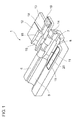
- Figure 1 is a perspective view showing a first embodiment of an optical fiber holder according to the invention.
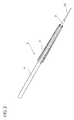
- Figure 2 is a perspective view showing an optical fiber cord to be held by the optical fiber holder according to the invention.
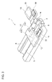
- Figure 3 is a perspective view showing a procedure of holding a coated optical fiber accommodated in an optical fiber cord by using the optical fiber holder according to the first embodiment.
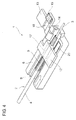
- Figure 4 is a perspective view showing the procedure of holding a coated optical fiber accommodated in an optical fiber cord by using the optical fiber holder according to the first embodiment.
- Figure 5 is a perspective view showing the procedure of holding a coated optical fiber accommodated in an optical fiber cord by using the optical fiber holder according to the first embodiment.
- Figure 6 is a perspective view showing a procedure of removing the optical fiber cord out of the optical fiber holder according to the first embodiment.
- Figure 7 is a perspective view showing the procedure of removing the optical fiber cord out of the optical fiber holder according to the first embodiment.
- Figure 9 is a perspective view of the optical fiber holder according to the second embodiment viewed from below.
- Figure 10 is a perspective view showing a procedure of holding a coated optical fiber accommodated in an optical fiber cord by using the optical fiber holder according to the second embodiment.
- Figure 11 is a perspective view showing the procedure of holding a coated optical fiber accommodated in an optical fiber cord by using the optical fiber holder according to the second embodiment.
- Figure 12 is a perspective view showing the procedure of holding a coated optical fiber accommodated in an optical fiber cord by using the optical fiber holder according to the second embodiment.
- Figure 13 is a perspective view showing the procedure of holding a coated optical fiber accommodated in an optical fiber cord by using the optical fiber holder according to the second embodiment.
- Figure 14 is a perspective view showing the procedure of holding a coated optical fiber accommodated in an optical fiber cord by using the optical fiber holder according to the second embodiment.
- Figure 15 is a perspective view showing the procedure of holding a coated optical fiber accommodated in an optical fiber cord by using the optical fiber holder according to the second embodiment.
- Figure 16 is a perspective view showing a procedure of removing the optical fiber cord out of the optical fiber holder according to the second embodiment.
- Figure 17 is a perspective view showing the procedure of removing the optical fiber cord out of the optical fiber holder according to the second embodiment.
- Figure 1 is a perspective view showing an optical fiber holder 1, which is a first embodiment according to the invention.
- the optical fiber holder 1 holds a coated optical fiber of an optical fiber cord, for example, when the coated optical fiber is fusion spliced to a coated optical fiber of another optical fiber cord.
- Figure 2 is a perspective view showing an optical fiber cord 2 to be held by the optical fiber holder 1.
- the optical fiber cord 2 includes a coated optical fiber 3 having a bare fiber 3a coated with a resin, a cord jacket 4 that surrounds the coated optical fiber 3, and high strength fibers 5 interposed between the coated optical fiber 3 and the cord jacket 4.
- the diameter of the coated optical fiber 3 ranges from about 0.25 to 0.90 mm.
- the diameter of the cord jacket 4 ranges from about 2 to 5 mm.
- the cord jacket 4 is made, for example, of PVC (polyvinyl chloride).
- the high strength fibers 5 are made, for example, of Kevler ® (aromatic polyamide-based resin).
- the optical fiber holder 1 includes a holder main body 6 having a substantially box-like shape.
- the holder main body 6 includes a fiber receiving groove 7 that has a V-like cross-sectional shape, and receives and positions the coated optical fiber 3 exposed out of the optical fiber cord 2 from which the cord jacket 4 is removed at the tip thereof and a cord receiving groove 8 that has a semicircular cross-sectional shape and receives the cord jacket 4.
- the fiber receiving groove 7 and the cord receiving groove 8 are formed to be continuous with each other.
- a cord introducing groove 9 having a semicircular cross-sectional shape whose radius is greater than that of the cord receiving groove 8 is formed behind the cord receiving groove 8 (on the opposite side of the cord receiving groove 8 to the fiber receiving groove 7) in the holder main body 6.
- a tapered groove 10 that tapers down from the cord introducing groove 9 to the cord receiving groove 8 is formed between the cord receiving groove 8 and the cord introducing groove 9 in the holder main body 6.
- the area including the cord receiving groove 8 and the tapered groove 10 in the holder main body 6 forms a cord holding base 11.
- a cord holding cover 12 and a fiber pressing cover 13, which are made of a metal, are pivotally attached (in an openable and closable manner) to the holder main body 6 via a shaft 14 provided on one side thereof.
- a cord receiving groove 15 having a semicircular cross-sectional shape and corresponding to the cord receiving groove 8 of the holder main body 6 and a tapered groove 16 corresponding to the tapered groove 10 of the holder main body 6 are formed on the back side of the cord holding cover 12.
- the cord receiving groove 15 and the tapered groove 16 when the cord holding cover 12 is closed on the holder main body 6, cooperate with the cord receiving groove 8 and the tapered groove 10 to form an insertion through hole 17 ( Figure 3 ) that has a circular cross-sectional shape and allows the optical fiber cord 2 to be inserted.
- the insertion through hole 17 includes an equiradial hole 17a formed by the cord receiving grooves 8 and 15 and a tapered hole 17b formed by the tapered grooves 10 and 16.
- the diameter of the equiradial hole 17a is slightly greater than that of the cord jacket 4 of the optical fiber cord 2.
- the equiradial hole 17a has a diameter that allows the high strength fibers 5, which are exposed along with the coated optical fiber 3, to come into contact with the inner wall surfaces of the holder main body 6 (cord holding base 11) and the cord holding cover 12, which form the insertion through hole 17, when the optical fiber cord 2 is inserted into the insertion through hole 17.
- the diameter of the equiradial hole 17a is about 3.4 mm.
- the fiber pressing cover 13 presses the coated optical fiber 3 received in the fiber receiving groove 7 of the holder main body 6 against the holder main body 6.
- a groove 18 having a rectangular cross-sectional shape and corresponding to the cord receiving groove 8 of the holder main body 6 is formed on the back side of the fiber pressing cover 13.
- a rubber 19 that presses the coated optical fiber 3 strongly enough without any damage thereto is further attached to the back side of the fiber pressing cover 13.
- the magnet 20 allows, when the cord holding cover 12 and the fiber pressing cover 13 are closed on the holder main body 6, the cord holding cover 12 and the fiber pressing cover 13 to be readily and securely fixed to the holder main body 6.
- Figures 3 to 5 are perspective views showing a procedure of holding the coated optical fiber 3 accommodated in the optical fiber cord 2 by using the optical fiber holder 1.
- the cord jacket 4 at the tip of the optical fiber cord 2 is so removed that the coated optical fiber 3 and the high strength fibers 5 are exposed.
- the length of the exposed coated optical fiber 3 and high strength fibers 5 ranges from about 30 to 40 mm.
- the optical fiber holder 1 with the cord holding cover 12 and the fiber pressing cover 13 open is so operated that the cord holding cover 12 is closed on the holder main body 6 to form the insertion through hole 17 having a circular cross-sectional shape ( Figure 3 ).
- the optical fiber cord 2 is then inserted into the insertion through hole 17 from the side where the cord introducing groove 9 of the holder main body 6 is present ( Figure 4 ).
- the optical fiber cord 2 can be readily inserted into the insertion through hole 17.
- the exposed high strength fibers 5, which are flexible are so guided that they come into contact with the inner wall surfaces of the holder main body 6 and the cord holding cover 12, which form the insertion through hole 17, and naturally follow the inner wall surfaces rearward.
- the exposed high strength fibers 5 are therefore disposed around the cord jacket 4 and will not protrude out of the insertion through hole 17 but only the exposed coated optical fiber 3 will protrude out thereof. In this process, it is desirable that the exposed high strength fibers 5 are routed rearward to some extent in advance relative to the optical fiber cord 2 (on the side where the cord jacket 4 is present) and that the optical fiber cord 2 is then inserted into the insertion through hole 17 with the high strength fibers 5 routed rearward.
- the cord jacket 4 of the optical fiber cord 2 is then allowed to protrude out of the insertion through hole 17, and the coated optical fiber 3 is placed on the fiber receiving groove 7 of the holder main body 6. At this point, the tip of the cord jacket 4 is allowed to come into contact with a wall surface that forms the boundary (rear end of fiber receiving groove 7) between the fiber receiving groove 7 and the cord receiving groove 8 of the holder main body 6.
- the fiber pressing cover 13 is closed on the holder main body 6 ( Figure 5 ).
- the fiber pressing cover 13 thus presses the coated optical fiber 3 against the holder main body 6.
- an end portion (tip) of the coated optical fiber 3 is so removed that the bare fiber 3a is exposed, and the end face of the bare fiber 3a is so cut with a dedicated cutter that the cut face is mirror-finished.
- Another optical fiber holder 1 in which another coated optical fiber 3 is held is provided.
- the two sets of optical fiber holders 1 are so placed in a fusion apparatus (not shown) that they face each other, and the bare fibers 3a of the coated optical fibers 3 are fusion spliced to each other.
- Figures 6 and 7 are perspective views showing a procedure of removing the optical fiber cord 2 out of the optical fiber holder 1. After the fusion splicing is completed, the cord holding cover 12 and the fiber pressing cover 13 are opened ( Figure 6 ). The optical fiber cord 2 having been fusion spliced to the other optical fiber cord (not shown) is then removed out of the holder main body 6 ( Figure 7 ).
- the optical fiber cord 2 in the process of placing the optical fiber cord 2 in the optical fiber holder 1, the optical fiber cord 2 is inserted into the insertion through hole 17 with the cord holding cover 12 closed on the holder main body 6, and the exposed high strength fibers 5 come into contact with the inner wall surfaces of the holder main body 6 and the cord holding cover 12, which form the insertion through hole 17, naturally follow the inner wall surfaces rearward, and are disposed around the cord jacket 4.
- the high strength fibers 5 can thus be handled readily with no loss of splicing quality when the optical fiber cord 2 undergoes fusion splicing. As a result, the operation time can be shortened and the operation efficiency can be improved.
- the fusion splicing of the optical fiber cord 2 can therefore be stably performed with high quality.
- the cord holding base 11 is integrated with the holder main body 6, the number of parts of the optical fiber holder 1 is reduced and the structure thereof is simplified.
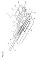
- FIG 8 is a perspective view showing an optical fiber holder 30 according to a second embodiment of the invention.
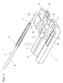
- Figure 9 is a perspective view of the optical fiber holder 30 viewed from below.
- the optical fiber holder 30 includes a holder main body 31 having a substantially box-like shape.
- a fiber receiving groove 32 that has a V-like cross-sectional shape and receives and positions the coated optical fiber 3 exposed out of the optical fiber cord 2 ( Figure 2 ) is formed in an end portion of the holder main body 31 on one side, and a cord introducing groove 33 having a semicircular cross-sectional shape is formed in an end portion of the holder main body 31 on the other side.
- a cord holding base 34 is pivotally attached (in an openable and closable manner) to the holder main body 31 via a shaft 35 provided on one side thereof.
- the cord holding base 34 is so configured that stopper means (not shown) limits the pivotal motion of the cord holding base 34 relative to the holder main body 31 to a predetermined angle (30 degrees, for example).
- the cord holding base 34 when closed on the holder main body 31, is located between the fiber receiving groove 32 and the cord introducing groove 33.
- the cord holding base 34 has a cord receiving groove 36 that is positioned on the side where the fiber receiving groove 32 is present, has a semicircular cross-sectional shape, and receives the cord jacket 4 of the optical fiber cord 2, and a tapered groove 37 that is positioned on the side where the cord introducing groove 33 is present and tapers down from the cord introducing groove 33 to the cord receiving groove 36.
- a cord holding cover 38 and a fiber pressing cover 39 which are made of a metal, are pivotally attached (in an openable and closable manner) to the holder main body 31 via the shaft 35.
- a cord receiving groove 40 having a semicircular cross-sectional shape and corresponding to the cord receiving groove 36 of the holder main body 31 and a tapered groove 41 corresponding to the tapered groove 37 of the holder main body 31 are formed on the back side of the cord holding cover 38.
- the cord receiving groove 40 and the tapered groove 41 cooperate with the cord receiving groove 36 and the tapered groove 37 to form an insertion through hole 42 ( Figure 10 ) that has a circular cross-sectional shape and allows the optical fiber cord 2 to be inserted.
- the diameter of the insertion through hole 42 is equal to that of the insertion through hole 17 in the first embodiment.
- a stepped portion 43 is provided on the front side of the cord holding cover 38 on the side adjacent to the fiber pressing cover 39.
- the fiber pressing cover 39 presses the coated optical fiber 3 received in the fiber receiving groove 32 of the holder main body 31 against the holder main body 31.
- a groove 44 having a cross-sectional being rectangular is formed on the back side of the fiber pressing cover 39.
- the rubber 19 is further attached to the back side of the fiber pressing cover 39.
- a stepped portion 45 that engages with the stepped portion 43 of the cord holding cover 38 is provided on the back side of the fiber pressing cover 39 adjacent to the cord holding cover 38.
- the magnet 20, which attracts the cord holding cover 38 and the fiber pressing cover 39, which are made of a metal, is embedded in the holder main body 31 on the other side thereof.
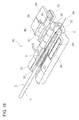
- Figures 10 to 15 are perspective views showing a procedure of holding the coated optical fiber 3 accommodated in the optical fiber cord 2 by using the optical fiber holder 30.
- the cord jacket 4 at the tip of the optical fiber cord 2 is so removed that the coated optical fiber 3 and the high strength fibers 5 are exposed.
- the coating of an end portion of the coated optical fiber 3 is so removed that the bare fiber 3a is exposed, and the end face of the bare fiber 3a is so cut that the cut face is mirror-finished.
- the length of the exposed coated optical fiber 3 is, for example, about 15 mm, for example, about 10 mm of which is the length of the exposed bare fiber 3a.
- the length of the exposed high strength fibers 5 ranges, for example, from about 30 to 40 mm.
- the optical fiber holder 30 with the cord holding base 34 closed and the cord holding cover 38 and the fiber pressing cover 39 open is so operated that the cord holding cover 38 is closed on the holder main body 31 to form the insertion through hole 42 having a cross-section being circular ( Figure 10 ).
- the cord holding base 34 is then manually pressed from the bottom side of the holder main body 31, so that the cord holding base 34 along with the cord holding cover 38 is lifted relative to the holder main body 31 ( Figure 11 ). In this process, the cord holding base 34 and the cord holding cover 38 are lifted to a point where the stopper means (not shown) limits the pivotal motion thereof.
- the optical fiber cord 2 is inserted into the insertion through hole 42 with the other hand from the side where the cord introducing groove 33 is present ( Figure 12 ).
- the exposed high strength fibers 5 are so guided that they come into contact with the inner wall surfaces of the cord holding base 34 and the cord holding cover 38, which form the insertion through hole 42, and naturally follow the inner wall surfaces rearward, the high strength fibers 5 are disposed around the cord jacket 4.
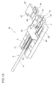
- the one hand releases the cord holding base 34 to close the cord holding base 34 and the cord holding cover 38 on the holder main body 31 ( Figure 13 ).
- the coated optical fiber 3 is placed on the fiber receiving groove 32 of the holder main body 31.
- the tip of the cord jacket 4 is allowed to come into contact with the wall surface that forms the rear end of the fiber receiving groove 32 of the holder main body 31.
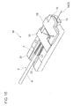
- the fiber pressing cover 39 is then closed on the holder main body 31, so that the fiber pressing cover 39 presses the coated optical fiber 3 against the holder main body 31 ( Figure 15 ).
- the stepped portion 45 of the fiber pressing cover 39 is placed on the stepped portion 43 of the cord holding cover 38.
- another optical fiber holder 30 in which another coated optical fiber 3 is held is provided.
- the two sets of optical fiber holders 30 are so placed in a fusion apparatus (not shown) that they face each other, and the bare fibers 3a of the coated optical fibers 3 are fusion spliced to each other.
- Figures 16 and 17 are perspective views showing a procedure of removing the optical fiber cord 2 out of the optical fiber holder 30.
- the cord holding cover 38 and the fiber pressing cover 39 are opened ( Figure 16 ).
- opening the cord holding cover 38 allows the cord holding cover 38 to press and open the fiber pressing cover 39.
- the fiber pressing cover 39 can first be opened and the cord holding cover 38 can then be opened.
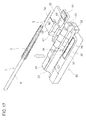
- the optical fiber cord 2 having been fusion spliced to the other optical fiber cord (not shown) is then removed out of the holder main body 31 ( Figure 17 ).
- the cord holding base 34 and the cord holding cover 38 are lifted relative to the holder main body 31 with the insertion through hole 42 formed by the cord holding base 34 and the cord holding cover 38, whereby the insertion through hole 42 is positioned apart from the holder main body 31.
- the bare fiber 3a exposed at the tip of the optical fiber cord 2 will not come into contact with the holder main body 31.
- High-quality fusion splicing can thus be stably performed even when the coated optical fiber 3 has undergone end treatment in advance.
- each of the cord receiving grooves 8, 15 and the cord receiving grooves 36, 40 has a cross-section being semicircular, but the shape of each of the cord receiving grooves is not limited to a semicircular cross-sectional shape and can be any cross-sectional shape that cooperates with the cross-sectional shape of the opposing cord receiving groove to form a cross-section being circular of the insertion through hole. Further, the insertion through hole does not necessarily have a cross-section being circular.
- the invention is applicable to a process of holding a coated optical fiber of an optical fiber cord when the coated optical fiber is fusion spliced to a coated optical fiber of another optical fiber cord.
- Patent Literature 1 Japanese Patent Laid-Open No. 11-231164
Landscapes
- Physics & Mathematics (AREA)
- General Physics & Mathematics (AREA)
- Optics & Photonics (AREA)
- Engineering & Computer Science (AREA)
- Plasma & Fusion (AREA)
- Mechanical Coupling Of Light Guides (AREA)
- Light Guides In General And Applications Therefor (AREA)
Abstract
Description
- The present invention relates to an optical fiber holder for holding a coated optical fiber accommodated in an optical fiber cord having built-in high strength fibers and a method for holding the coated optical fiber.
- Japanese Patent Laid-Open No.
11-231164 - To hold the coated optical fiber by using the optical fiber holder, the high strength fibers are separated and routed backward through both side portions of the space formed in the holder main body. Since the high strength fibers are tightly disposed around the coated optical fiber, separating the high strength fibers from the coated optical fiber and taking them out of the space is a cumbersome, time-consuming task. Further, since an operator manually separates the high strength fibers and takes them out, the quality of the task depends on the skill of the operator. For example, when the coated optical fiber is fusion spliced to another, a low-skilled operator can accidentally bum the high strength fibers due to high temperature in a fusion discharge process or allow the high strength fibers to come into contact with the fusion spliced portion, resulting in a decrease in quality of the spliced coated optical fibers.
- An object of the invention is to provide an optical fiber holder that allows high strength fibers to be readily handled with no loss of splicing quality when the optical fiber holder holds a coated optical fiber and a method for holding a coated optical fiber.
- To achieve the object described above, a novel optical fiber holder for holding a coated optical fiber accommodated in an optical fiber cord having built-in high strength fibers is provided. The optical fiber holder includes a holder main body including: a fiber receiving groove to receive the coated optical fiber exposed out of the optical fiber cord from which a cord jacket is removed at the tip thereof; a cord holding base including a first cord receiving groove to receive the cord jacket of the optical fiber cord; a cord holding cover that is attached to the holder main body in an openable and closable manner and includes a second receiving groove that cooperates with the first cord receiving groove to form an insertion through hole into which the optical fiber cord is inserted; and a fiber pressing cover that is attached to the holder main body in an openable and closable manner and presses the coated optical fiber received in the fiber receiving groove against the holder main body, and the insertion through hole is shaped and dimensioned such that the high strength fibers of the optical fiber cord being inserted into the insertion through hole, the high strength fibers being exposed along with the coated optical fiber, come into contact with inner wall surfaces of the cord holding base and the cord holding cover, which form the insertion through hole.
- In the optical fiber holder according to the invention, the cord holding base can be integrated with the holder main body or can be attached to the holder main body in an openable and closable manner independent of the cord holding cover.
- Another aspect of the invention provides a novel method for holding a coated optical fiber accommodated in an optical fiber cord having built-in high strength fibers. The method for holding a coated optical fiber includes the steps of: providing the optical fiber holder described above; exposing the coated optical fiber and the high strength fibers by removing a cord jacket at the tip of the optical fiber cord; inserting the optical fiber cord into the insertion through hole formed by the cord holding base and the cord holding cover so that the coated optical fiber is received by the fiber receiving groove; and pressing the coated optical fiber with the fiber pressing cover against the holder main body.
- According to the invention, the high strength fibers can be handled readily with no loss of splicing quality in the process of holding the coated optical fiber by using the optical fiber holder. As a result, a burden on an operator can be reduced. Further, the operation time can be shortened and the operation efficiency can be improved.
-
Figure 1 is a perspective view showing a first embodiment of an optical fiber holder according to the invention. -
Figure 2 is a perspective view showing an optical fiber cord to be held by the optical fiber holder according to the invention. -
Figure 3 is a perspective view showing a procedure of holding a coated optical fiber accommodated in an optical fiber cord by using the optical fiber holder according to the first embodiment. -
Figure 4 is a perspective view showing the procedure of holding a coated optical fiber accommodated in an optical fiber cord by using the optical fiber holder according to the first embodiment. -
Figure 5 is a perspective view showing the procedure of holding a coated optical fiber accommodated in an optical fiber cord by using the optical fiber holder according to the first embodiment. -
Figure 6 is a perspective view showing a procedure of removing the optical fiber cord out of the optical fiber holder according to the first embodiment. -
Figure 7 is a perspective view showing the procedure of removing the optical fiber cord out of the optical fiber holder according to the first embodiment. -
Figure 8 is a perspective view showing a second embodiment of the optical fiber holder according to the invention. -
Figure 9 is a perspective view of the optical fiber holder according to the second embodiment viewed from below. -
Figure 10 is a perspective view showing a procedure of holding a coated optical fiber accommodated in an optical fiber cord by using the optical fiber holder according to the second embodiment. -
Figure 11 is a perspective view showing the procedure of holding a coated optical fiber accommodated in an optical fiber cord by using the optical fiber holder according to the second embodiment. -
Figure 12 is a perspective view showing the procedure of holding a coated optical fiber accommodated in an optical fiber cord by using the optical fiber holder according to the second embodiment. -
Figure 13 is a perspective view showing the procedure of holding a coated optical fiber accommodated in an optical fiber cord by using the optical fiber holder according to the second embodiment. -
Figure 14 is a perspective view showing the procedure of holding a coated optical fiber accommodated in an optical fiber cord by using the optical fiber holder according to the second embodiment. -
Figure 15 is a perspective view showing the procedure of holding a coated optical fiber accommodated in an optical fiber cord by using the optical fiber holder according to the second embodiment. -
Figure 16 is a perspective view showing a procedure of removing the optical fiber cord out of the optical fiber holder according to the second embodiment. -
Figure 17 is a perspective view showing the procedure of removing the optical fiber cord out of the optical fiber holder according to the second embodiment. - Embodiments of the invention will be described below with reference to the drawings. The drawings are provided to help describing the invention but are not intended to limit the scope of the invention. In the drawings, to avoid redundant description, the identical reference numerals denote the same portions. The drawings are not necessarily to scale.
-
Figure 1 is a perspective view showing anoptical fiber holder 1, which is a first embodiment according to the invention. Theoptical fiber holder 1 holds a coated optical fiber of an optical fiber cord, for example, when the coated optical fiber is fusion spliced to a coated optical fiber of another optical fiber cord. -
Figure 2 is a perspective view showing anoptical fiber cord 2 to be held by theoptical fiber holder 1. Theoptical fiber cord 2 includes a coatedoptical fiber 3 having abare fiber 3a coated with a resin, acord jacket 4 that surrounds the coatedoptical fiber 3, andhigh strength fibers 5 interposed between the coatedoptical fiber 3 and thecord jacket 4. The diameter of the coatedoptical fiber 3 ranges from about 0.25 to 0.90 mm. The diameter of thecord jacket 4 ranges from about 2 to 5 mm. Thecord jacket 4 is made, for example, of PVC (polyvinyl chloride). Thehigh strength fibers 5 are made, for example, of Kevler® (aromatic polyamide-based resin). - Referring back to
Figure 1 , theoptical fiber holder 1 includes a holdermain body 6 having a substantially box-like shape. The holdermain body 6 includes afiber receiving groove 7 that has a V-like cross-sectional shape, and receives and positions the coatedoptical fiber 3 exposed out of theoptical fiber cord 2 from which thecord jacket 4 is removed at the tip thereof and acord receiving groove 8 that has a semicircular cross-sectional shape and receives thecord jacket 4. Thefiber receiving groove 7 and thecord receiving groove 8 are formed to be continuous with each other. - A
cord introducing groove 9 having a semicircular cross-sectional shape whose radius is greater than that of thecord receiving groove 8 is formed behind the cord receiving groove 8 (on the opposite side of thecord receiving groove 8 to the fiber receiving groove 7) in the holdermain body 6. Atapered groove 10 that tapers down from thecord introducing groove 9 to thecord receiving groove 8 is formed between thecord receiving groove 8 and thecord introducing groove 9 in the holdermain body 6. The area including thecord receiving groove 8 and thetapered groove 10 in the holdermain body 6 forms acord holding base 11. Acord holding cover 12 and afiber pressing cover 13, which are made of a metal, are pivotally attached (in an openable and closable manner) to the holdermain body 6 via ashaft 14 provided on one side thereof. - A
cord receiving groove 15 having a semicircular cross-sectional shape and corresponding to thecord receiving groove 8 of the holdermain body 6 and atapered groove 16 corresponding to thetapered groove 10 of the holdermain body 6 are formed on the back side of thecord holding cover 12. Thecord receiving groove 15 and thetapered groove 16, when thecord holding cover 12 is closed on the holdermain body 6, cooperate with thecord receiving groove 8 and thetapered groove 10 to form an insertion through hole 17 (Figure 3 ) that has a circular cross-sectional shape and allows theoptical fiber cord 2 to be inserted. The insertion throughhole 17 includes anequiradial hole 17a formed by thecord receiving grooves tapered hole 17b formed by thetapered grooves - The diameter of the
equiradial hole 17a is slightly greater than that of thecord jacket 4 of theoptical fiber cord 2. Specifically, theequiradial hole 17a has a diameter that allows thehigh strength fibers 5, which are exposed along with the coatedoptical fiber 3, to come into contact with the inner wall surfaces of the holder main body 6 (cord holding base 11) and thecord holding cover 12, which form the insertion throughhole 17, when theoptical fiber cord 2 is inserted into the insertion throughhole 17. For example, when the diameter of thecord jacket 4 is 3 mm, the diameter of theequiradial hole 17a is about 3.4 mm. - The
fiber pressing cover 13 presses the coatedoptical fiber 3 received in thefiber receiving groove 7 of the holdermain body 6 against the holdermain body 6. Agroove 18 having a rectangular cross-sectional shape and corresponding to thecord receiving groove 8 of the holdermain body 6 is formed on the back side of thefiber pressing cover 13. Arubber 19 that presses the coatedoptical fiber 3 strongly enough without any damage thereto is further attached to the back side of thefiber pressing cover 13. - A
magnet 20 that attracts thecord holding cover 12 and thefiber pressing cover 13, which are made of a metal, is embedded in the holdermain body 6 on the other side thereof. Themagnet 20 allows, when thecord holding cover 12 and thefiber pressing cover 13 are closed on the holdermain body 6, thecord holding cover 12 and thefiber pressing cover 13 to be readily and securely fixed to the holdermain body 6. - A method for holding the coated
optical fiber 3 of theoptical fiber cord 2 by using theoptical fiber holder 1 when the coatedoptical fiber 3 is fusion spliced will next be described.Figures 3 to 5 are perspective views showing a procedure of holding the coatedoptical fiber 3 accommodated in theoptical fiber cord 2 by using theoptical fiber holder 1. - First, the
cord jacket 4 at the tip of theoptical fiber cord 2 is so removed that the coatedoptical fiber 3 and thehigh strength fibers 5 are exposed. At this point, the length of the exposed coatedoptical fiber 3 andhigh strength fibers 5 ranges from about 30 to 40 mm. Subsequently, theoptical fiber holder 1 with thecord holding cover 12 and thefiber pressing cover 13 open is so operated that thecord holding cover 12 is closed on the holdermain body 6 to form the insertion throughhole 17 having a circular cross-sectional shape (Figure 3 ). - The
optical fiber cord 2 is then inserted into the insertion throughhole 17 from the side where thecord introducing groove 9 of the holdermain body 6 is present (Figure 4 ). In this process, since thetapered hole 17b is formed in a rear portion of the insertion throughhole 17, theoptical fiber cord 2 can be readily inserted into the insertion throughhole 17. When theoptical fiber cord 2 is inserted into the insertion throughhole 17, the exposedhigh strength fibers 5, which are flexible, are so guided that they come into contact with the inner wall surfaces of the holdermain body 6 and thecord holding cover 12, which form the insertion throughhole 17, and naturally follow the inner wall surfaces rearward. The exposedhigh strength fibers 5 are therefore disposed around thecord jacket 4 and will not protrude out of the insertion throughhole 17 but only the exposed coatedoptical fiber 3 will protrude out thereof. In this process, it is desirable that the exposedhigh strength fibers 5 are routed rearward to some extent in advance relative to the optical fiber cord 2 (on the side where thecord jacket 4 is present) and that theoptical fiber cord 2 is then inserted into the insertion throughhole 17 with thehigh strength fibers 5 routed rearward. - The
cord jacket 4 of theoptical fiber cord 2 is then allowed to protrude out of the insertion throughhole 17, and the coatedoptical fiber 3 is placed on thefiber receiving groove 7 of the holdermain body 6. At this point, the tip of thecord jacket 4 is allowed to come into contact with a wall surface that forms the boundary (rear end of fiber receiving groove 7) between thefiber receiving groove 7 and thecord receiving groove 8 of the holdermain body 6. - Subsequently, the
fiber pressing cover 13 is closed on the holder main body 6 (Figure 5 ). Thefiber pressing cover 13 thus presses the coatedoptical fiber 3 against the holdermain body 6. - Thereafter, the coating of an end portion (tip) of the coated
optical fiber 3 is so removed that thebare fiber 3a is exposed, and the end face of thebare fiber 3a is so cut with a dedicated cutter that the cut face is mirror-finished. Anotheroptical fiber holder 1 in which another coatedoptical fiber 3 is held is provided. The two sets ofoptical fiber holders 1 are so placed in a fusion apparatus (not shown) that they face each other, and thebare fibers 3a of the coatedoptical fibers 3 are fusion spliced to each other. In this process, since the exposedhigh strength fibers 5 are routed rearward relative to the exposed coatedoptical fibers 3 and disposed around thecord jackets 4, thehigh strength fibers 5 will not burn due to high temperature in the fusion discharge process or come into contact with the fusion spliced portion, whereby the quality of the fusion splicing will not be degraded. -
Figures 6 and7 are perspective views showing a procedure of removing theoptical fiber cord 2 out of theoptical fiber holder 1. After the fusion splicing is completed, thecord holding cover 12 and thefiber pressing cover 13 are opened (Figure 6 ). Theoptical fiber cord 2 having been fusion spliced to the other optical fiber cord (not shown) is then removed out of the holder main body 6 (Figure 7 ). - In the first embodiment described above, in the process of placing the
optical fiber cord 2 in theoptical fiber holder 1, theoptical fiber cord 2 is inserted into the insertion throughhole 17 with thecord holding cover 12 closed on the holdermain body 6, and the exposedhigh strength fibers 5 come into contact with the inner wall surfaces of the holdermain body 6 and thecord holding cover 12, which form the insertion throughhole 17, naturally follow the inner wall surfaces rearward, and are disposed around thecord jacket 4. Thehigh strength fibers 5 can thus be handled readily with no loss of splicing quality when theoptical fiber cord 2 undergoes fusion splicing. As a result, the operation time can be shortened and the operation efficiency can be improved. - Further, since no special skill or experience is required to handle the
high strength fibers 5, skill and other personal differences of operators will not affect the handling of thehigh strength fibers 5. The fusion splicing of theoptical fiber cord 2 can therefore be stably performed with high quality. In addition, since thecord holding base 11 is integrated with the holdermain body 6, the number of parts of theoptical fiber holder 1 is reduced and the structure thereof is simplified. -
Figure 8 is a perspective view showing anoptical fiber holder 30 according to a second embodiment of the invention.Figure 9 is a perspective view of theoptical fiber holder 30 viewed from below. Theoptical fiber holder 30 includes a holdermain body 31 having a substantially box-like shape. Afiber receiving groove 32 that has a V-like cross-sectional shape and receives and positions the coatedoptical fiber 3 exposed out of the optical fiber cord 2 (Figure 2 ) is formed in an end portion of the holdermain body 31 on one side, and acord introducing groove 33 having a semicircular cross-sectional shape is formed in an end portion of the holdermain body 31 on the other side. - A
cord holding base 34 is pivotally attached (in an openable and closable manner) to the holdermain body 31 via ashaft 35 provided on one side thereof. Thecord holding base 34 is so configured that stopper means (not shown) limits the pivotal motion of thecord holding base 34 relative to the holdermain body 31 to a predetermined angle (30 degrees, for example). - The
cord holding base 34, when closed on the holdermain body 31, is located between thefiber receiving groove 32 and thecord introducing groove 33. Thecord holding base 34 has acord receiving groove 36 that is positioned on the side where thefiber receiving groove 32 is present, has a semicircular cross-sectional shape, and receives thecord jacket 4 of theoptical fiber cord 2, and a taperedgroove 37 that is positioned on the side where thecord introducing groove 33 is present and tapers down from thecord introducing groove 33 to thecord receiving groove 36. Acord holding cover 38 and afiber pressing cover 39, which are made of a metal, are pivotally attached (in an openable and closable manner) to the holdermain body 31 via theshaft 35. - A
cord receiving groove 40 having a semicircular cross-sectional shape and corresponding to thecord receiving groove 36 of the holdermain body 31 and a taperedgroove 41 corresponding to the taperedgroove 37 of the holdermain body 31 are formed on the back side of thecord holding cover 38. Thecord receiving groove 40 and the taperedgroove 41 cooperate with thecord receiving groove 36 and the taperedgroove 37 to form an insertion through hole 42 (Figure 10 ) that has a circular cross-sectional shape and allows theoptical fiber cord 2 to be inserted. The diameter of the insertion throughhole 42 is equal to that of the insertion throughhole 17 in the first embodiment. A steppedportion 43 is provided on the front side of thecord holding cover 38 on the side adjacent to thefiber pressing cover 39. - The
fiber pressing cover 39 presses the coatedoptical fiber 3 received in thefiber receiving groove 32 of the holdermain body 31 against the holdermain body 31. Agroove 44 having a cross-sectional being rectangular is formed on the back side of thefiber pressing cover 39. Therubber 19 is further attached to the back side of thefiber pressing cover 39. A steppedportion 45 that engages with the steppedportion 43 of thecord holding cover 38 is provided on the back side of thefiber pressing cover 39 adjacent to thecord holding cover 38. Themagnet 20, which attracts thecord holding cover 38 and thefiber pressing cover 39, which are made of a metal, is embedded in the holdermain body 31 on the other side thereof. - A method for holding the coated
optical fiber 3 of theoptical fiber cord 2 by using theoptical fiber holder 30 when the coatedoptical fiber 3 is fusion spliced will next be described.Figures 10 to 15 are perspective views showing a procedure of holding the coatedoptical fiber 3 accommodated in theoptical fiber cord 2 by using theoptical fiber holder 30. - First, the
cord jacket 4 at the tip of theoptical fiber cord 2 is so removed that the coatedoptical fiber 3 and thehigh strength fibers 5 are exposed. Thereafter, the coating of an end portion of the coatedoptical fiber 3 is so removed that thebare fiber 3a is exposed, and the end face of thebare fiber 3a is so cut that the cut face is mirror-finished. At this point, the length of the exposed coatedoptical fiber 3 is, for example, about 15 mm, for example, about 10 mm of which is the length of the exposedbare fiber 3a. The length of the exposedhigh strength fibers 5 ranges, for example, from about 30 to 40 mm. - Subsequently, the
optical fiber holder 30 with thecord holding base 34 closed and thecord holding cover 38 and thefiber pressing cover 39 open is so operated that thecord holding cover 38 is closed on the holdermain body 31 to form the insertion throughhole 42 having a cross-section being circular (Figure 10 ). Thecord holding base 34 is then manually pressed from the bottom side of the holdermain body 31, so that thecord holding base 34 along with thecord holding cover 38 is lifted relative to the holder main body 31 (Figure 11 ). In this process, thecord holding base 34 and thecord holding cover 38 are lifted to a point where the stopper means (not shown) limits the pivotal motion thereof. - Subsequently, for example, with one hand pressing the
cord holding base 34 from the bottom side of the holdermain body 31, theoptical fiber cord 2 is inserted into the insertion throughhole 42 with the other hand from the side where thecord introducing groove 33 is present (Figure 12 ). In this process, since the exposedhigh strength fibers 5 are so guided that they come into contact with the inner wall surfaces of thecord holding base 34 and thecord holding cover 38, which form the insertion throughhole 42, and naturally follow the inner wall surfaces rearward, thehigh strength fibers 5 are disposed around thecord jacket 4. - After the
cord jacket 4 of theoptical fiber cord 2 protrudes out of the insertion throughhole 42, the one hand releases thecord holding base 34 to close thecord holding base 34 and thecord holding cover 38 on the holder main body 31 (Figure 13 ). At this point, the coatedoptical fiber 3 is placed on thefiber receiving groove 32 of the holdermain body 31. Subsequently, the tip of thecord jacket 4 is allowed to come into contact with the wall surface that forms the rear end of thefiber receiving groove 32 of the holdermain body 31. - The
fiber pressing cover 39 is then closed on the holdermain body 31, so that thefiber pressing cover 39 presses the coatedoptical fiber 3 against the holder main body 31 (Figure 15 ). At this point, the steppedportion 45 of thefiber pressing cover 39 is placed on the steppedportion 43 of thecord holding cover 38. Thereafter, anotheroptical fiber holder 30 in which another coatedoptical fiber 3 is held is provided. The two sets ofoptical fiber holders 30 are so placed in a fusion apparatus (not shown) that they face each other, and thebare fibers 3a of the coatedoptical fibers 3 are fusion spliced to each other. -
Figures 16 and17 are perspective views showing a procedure of removing theoptical fiber cord 2 out of theoptical fiber holder 30. After the fusion splicing is completed, thecord holding cover 38 and thefiber pressing cover 39 are opened (Figure 16 ). In this process, since the steppedportion 45 of thefiber pressing cover 39 has been placed on the steppedportion 43 of thecord holding cover 38, opening thecord holding cover 38 allows thecord holding cover 38 to press and open thefiber pressing cover 39. It is, of course, noted that thefiber pressing cover 39 can first be opened and thecord holding cover 38 can then be opened. Theoptical fiber cord 2 having been fusion spliced to the other optical fiber cord (not shown) is then removed out of the holder main body 31 (Figure 17 ). - In the second embodiment described above, in the process of placing the
optical fiber cord 2 in theoptical fiber holder 31, thecord holding base 34 and thecord holding cover 38 are lifted relative to the holdermain body 31 with the insertion throughhole 42 formed by thecord holding base 34 and thecord holding cover 38, whereby the insertion throughhole 42 is positioned apart from the holdermain body 31. As a result, when theoptical fiber cord 2 is inserted into the insertion throughhole 42, thebare fiber 3a exposed at the tip of theoptical fiber cord 2 will not come into contact with the holdermain body 31. High-quality fusion splicing can thus be stably performed even when the coatedoptical fiber 3 has undergone end treatment in advance. - The invention is not limited to the embodiments described above. For example, in the embodiments described above, each of the
cord receiving grooves cord receiving grooves - The invention is applicable to a process of holding a coated optical fiber of an optical fiber cord when the coated optical fiber is fusion spliced to a coated optical fiber of another optical fiber cord.
- Patent Literature 1: Japanese Patent Laid-Open No.
11-231164
Claims (4)
- An optical fiber holder for holding a coated optical fiber of an optical fiber cord, the optical fiber cord also including high strength fibers and a cord jacket, the optical fiber holder comprising:a holder main body including a fiber receiving groove to receive the coated optical fiber exposed out of the optical fiber cord from which the cord jacket is removed at a tip thereof;a cord holding base including a first cord receiving groove to receive the cord jacket of the optical fiber cord;a cord holding cover that is attached to the holder main body in an openable and closable manner and includes a second receiving groove that cooperates with the first cord receiving groove to form an insertion through hole into which the optical fiber cord is inserted; anda fiber pressing cover that is attached to the holder main body in an openable and closable manner and presses the coated optical fiber received in the fiber receiving groove against the holder main body,wherein the insertion through hole is shaped and dimensioned such that the high strength fibers of the optical fiber cord being inserted into the insertion through hole, the high strength fibers being exposed along with the coated optical fiber, come into contact with inner wall surfaces of the cord holding base and the cord holding cover, which form the insertion through hole.
- The optical fiber holder according to claim 1, wherein
the cord holding base is integrated with the holder main body. - The optical fiber holder according to claim 1, wherein
the cord holding base is attached to the holder main body in an openable and closable manner independent of the cord holding cover. - A method for holding a coated optical fiber of an optical fiber cord, the optical fiber cord also including high strength fibers and a cord jacket, the method comprising the step of:providing the optical fiber holder according to any one of claims 1 to 3;exposing the coated optical fiber and the high strength fibers by removing the cord jacket at a tip of the optical fiber cord;inserting the optical fiber cord into the insertion through hole formed by the cord holding base and the cord holding cover so that the coated optical fiber is received by the fiber receiving groove; andpressing the coated optical fiber with the fiber pressing cover against the holder main body.
Applications Claiming Priority (2)
| Application Number | Priority Date | Filing Date | Title |
|---|---|---|---|
| JP2009289425A JP5163631B2 (en) | 2009-12-21 | 2009-12-21 | Optical fiber holder and optical fiber core wire holding method |
| PCT/JP2010/072746 WO2011078072A1 (en) | 2009-12-21 | 2010-12-17 | Optical fiber holder and method for holding optical fiber core |
Publications (3)
| Publication Number | Publication Date |
|---|---|
| EP2518548A1 true EP2518548A1 (en) | 2012-10-31 |
| EP2518548A4 EP2518548A4 (en) | 2017-07-19 |
| EP2518548B1 EP2518548B1 (en) | 2018-06-20 |
Family
ID=44195598
Family Applications (1)
| Application Number | Title | Priority Date | Filing Date |
|---|---|---|---|
| EP10839302.6A Not-in-force EP2518548B1 (en) | 2009-12-21 | 2010-12-17 | Optical fiber holder and method for holding optical fiber core |
Country Status (6)
| Country | Link |
|---|---|
| US (1) | US8861920B2 (en) |
| EP (1) | EP2518548B1 (en) |
| JP (1) | JP5163631B2 (en) |
| KR (1) | KR101742341B1 (en) |
| CN (1) | CN102667558B (en) |
| WO (1) | WO2011078072A1 (en) |
Families Citing this family (17)
| Publication number | Priority date | Publication date | Assignee | Title |
|---|---|---|---|---|
| US20120281958A1 (en) * | 2011-05-05 | 2012-11-08 | 3M Innovative Properties Company | Re-enterable cabling system for in-building applications |
| JP6000177B2 (en) * | 2013-03-27 | 2016-09-28 | 株式会社神戸製鋼所 | Kneading machine and kneading method |
| WO2017119280A1 (en) * | 2016-01-04 | 2017-07-13 | 古河電気工業株式会社 | Optical fiber holding member and fusion machine |
| JP6159429B1 (en) * | 2016-01-18 | 2017-07-05 | 株式会社フジクラ | Optical connector and optical connector manufacturing method |
| JP6593794B2 (en) * | 2016-02-12 | 2019-10-23 | Seiオプティフロンティア株式会社 | Optical fiber holder and optical fiber cutting device to which the optical fiber holder can be attached |
| US10921527B2 (en) * | 2016-09-09 | 2021-02-16 | Sei Optifrontier Co., Ltd. | Optical fiber holder |
| CN107186616B (en) * | 2016-12-20 | 2020-04-10 | 北京航空航天大学 | LiNbO3 accompanying sheet clamp easy to assemble and disassemble in integrated mode |
| JP6965758B2 (en) * | 2018-01-10 | 2021-11-10 | 住友電気工業株式会社 | Optical module |
| US12099237B2 (en) | 2018-05-17 | 2024-09-24 | Commscope Technologies Llc | Fiber optic connector |
| CN109782391B (en) * | 2019-03-26 | 2020-09-22 | 浙江大丰管网有限公司 | Optical fiber fusion splicer |
| US11565378B2 (en) | 2019-07-02 | 2023-01-31 | Us Conec Ltd. | Fiber handling tool with spring loaded doors |
| WO2021133737A1 (en) * | 2019-12-23 | 2021-07-01 | Commscope Technologies Llc | Fiber optic processing systems and methods |
| CN113655571A (en) * | 2020-05-12 | 2021-11-16 | 富晋精密工业(晋城)有限公司 | Optical cable jig, optical fiber connector manufacturing method and optical fiber connector |
| CN117136322A (en) * | 2021-05-13 | 2023-11-28 | 住友电气工业株式会社 | Welding machine |
| US12345923B2 (en) | 2021-10-20 | 2025-07-01 | Senko Advanced Components, Inc. | Metallized optical fiber array module and fabrication method thereof |
| JP7878825B2 (en) * | 2021-11-11 | 2026-06-23 | 住友電工オプティフロンティア株式会社 | Optical fiber holder and fusion splicer |
| WO2026146575A1 (en) * | 2025-01-06 | 2026-07-09 | 株式会社フジクラ | Optical fiber holder |
Family Cites Families (10)
| Publication number | Priority date | Publication date | Assignee | Title |
|---|---|---|---|---|
| JPS6279209U (en) * | 1985-11-05 | 1987-05-21 | ||
| JPS6435404A (en) * | 1987-07-30 | 1989-02-06 | Sumitomo Electric Industries | Optical cable terminal machining device |
| US5366527A (en) * | 1993-04-05 | 1994-11-22 | Corning Incorporated | Method and apparatus for coating optical waveguide fibers |
| JP3542008B2 (en) * | 1998-02-13 | 2004-07-14 | 株式会社フジクラ | Optical fiber holder and optical fiber core fixing method |
| JP2002296426A (en) * | 2001-03-29 | 2002-10-09 | Furukawa Electric Co Ltd:The | Fiber core branching member |
| JP2003066265A (en) * | 2001-08-28 | 2003-03-05 | Nishi Nippon Electric Wire & Cable Co Ltd | Optical fiber cable connection method and connection part structure |
| JP3912531B2 (en) * | 2003-02-20 | 2007-05-09 | 住友電気工業株式会社 | Coated optical fiber |
| JP4843309B2 (en) * | 2005-12-26 | 2011-12-21 | 住友電気工業株式会社 | Optical fiber holder |
| JP4630266B2 (en) | 2006-12-15 | 2011-02-09 | 古河電気工業株式会社 | Optical fiber cord holder, method of manufacturing optical fiber cord with connector using the same, and fusion splicer |
| JP2009163004A (en) * | 2008-01-07 | 2009-07-23 | Sumitomo Electric Ind Ltd | Fiber holder |
-
2009
- 2009-12-21 JP JP2009289425A patent/JP5163631B2/en not_active Expired - Fee Related
-
2010
- 2010-12-17 US US13/513,454 patent/US8861920B2/en active Active
- 2010-12-17 WO PCT/JP2010/072746 patent/WO2011078072A1/en not_active Ceased
- 2010-12-17 KR KR1020127015994A patent/KR101742341B1/en not_active Expired - Fee Related
- 2010-12-17 CN CN201080058494.9A patent/CN102667558B/en not_active Expired - Fee Related
- 2010-12-17 EP EP10839302.6A patent/EP2518548B1/en not_active Not-in-force
Non-Patent Citations (1)
| Title |
|---|
| See references of WO2011078072A1 * |
Also Published As
| Publication number | Publication date |
|---|---|
| EP2518548A4 (en) | 2017-07-19 |
| US20120251068A1 (en) | 2012-10-04 |
| KR101742341B1 (en) | 2017-05-31 |
| CN102667558B (en) | 2014-04-09 |
| EP2518548B1 (en) | 2018-06-20 |
| CN102667558A (en) | 2012-09-12 |
| KR20120094497A (en) | 2012-08-24 |
| US8861920B2 (en) | 2014-10-14 |
| JP5163631B2 (en) | 2013-03-13 |
| WO2011078072A1 (en) | 2011-06-30 |
| JP2011128544A (en) | 2011-06-30 |
Similar Documents
| Publication | Publication Date | Title |
|---|---|---|
| US8861920B2 (en) | Optical fiber holder and method for holding coated optical fiber | |
| JP2010249967A (en) | Holder, fusion splicer and fusion splicing method | |
| EP3460546B1 (en) | Reinforcing device for optical fiber fusion spliced part and fusion splicer provided with same | |
| US9488781B2 (en) | Optical fiber holder and optical fiber fusion-connecting device | |
| JPWO2012133568A1 (en) | Optical fiber coating removal tool and coating removal method | |
| KR101794610B1 (en) | Holder of ribbon form optical fiber and method for connecting optical fiber connector for using therefor | |
| WO2020013059A1 (en) | Optical connector, method for manufacturing optical fiber cable provided with optical connector, and optical fiber connection tool | |
| JP2022048177A (en) | Terminal processing method for in-vehicle cables and their devices | |
| JP2010266567A (en) | Holder, fusion splicer and fusion splicing method | |
| JP5600009B2 (en) | Optical fiber core support member, optical connector mounting mechanism, optical connector, and optical fiber terminal processing method | |
| JP2016123215A (en) | Heat-shrinkable tube mounting device and heat-shrinkable tube mounting method | |
| JP2016080788A (en) | Optical fiber coating removal tool and optical fiber coating removal method | |
| JP3542008B2 (en) | Optical fiber holder and optical fiber core fixing method | |
| JP2014182336A (en) | Coating removal device | |
| CN107615122B (en) | Optical fiber holding member and fusion splicer | |
| JP6078667B1 (en) | Optical connector manufacturing method and tool | |
| JP6061964B2 (en) | Wire sheath removal unit and method of manufacturing wire harness | |
| JP4127661B2 (en) | Optical fiber cutter and optical fiber cutting method using the same | |
| JP2018189998A (en) | Optical fiber connector and connection method of optical fiber | |
| JP5199294B2 (en) | Optical fiber holder | |
| JP5999556B2 (en) | Optical fiber holder and fusion splicer | |
| JP2007121878A (en) | Optical connector connection tool | |
| JP2013015786A (en) | Optical connector | |
| JP2011002670A (en) | Method of splicing beveled end face optical fibers | |
| JP2013015785A (en) | Assembling method of optical connector |
Legal Events
| Date | Code | Title | Description |
|---|---|---|---|
| PUAI | Public reference made under article 153(3) epc to a published international application that has entered the european phase |
Free format text: ORIGINAL CODE: 0009012 |
|
| 17P | Request for examination filed |
Effective date: 20120612 |
|
| AK | Designated contracting states |
Kind code of ref document: A1 Designated state(s): AL AT BE BG CH CY CZ DE DK EE ES FI FR GB GR HR HU IE IS IT LI LT LU LV MC MK MT NL NO PL PT RO RS SE SI SK SM TR |
|
| DAX | Request for extension of the european patent (deleted) | ||
| RA4 | Supplementary search report drawn up and despatched (corrected) |
Effective date: 20170621 |
|
| RIC1 | Information provided on ipc code assigned before grant |
Ipc: G02B 6/255 20060101AFI20170615BHEP Ipc: G02B 6/00 20060101ALI20170615BHEP |
|
| GRAP | Despatch of communication of intention to grant a patent |
Free format text: ORIGINAL CODE: EPIDOSNIGR1 |
|
| STAA | Information on the status of an ep patent application or granted ep patent |
Free format text: STATUS: GRANT OF PATENT IS INTENDED |
|
| INTG | Intention to grant announced |
Effective date: 20180222 |
|
| GRAS | Grant fee paid |
Free format text: ORIGINAL CODE: EPIDOSNIGR3 |
|
| GRAA | (expected) grant |
Free format text: ORIGINAL CODE: 0009210 |
|
| STAA | Information on the status of an ep patent application or granted ep patent |
Free format text: STATUS: THE PATENT HAS BEEN GRANTED |
|
| AK | Designated contracting states |
Kind code of ref document: B1 Designated state(s): AL AT BE BG CH CY CZ DE DK EE ES FI FR GB GR HR HU IE IS IT LI LT LU LV MC MK MT NL NO PL PT RO RS SE SI SK SM TR |
|
| REG | Reference to a national code |
Ref country code: GB Ref legal event code: FG4D |
|
| REG | Reference to a national code |
Ref country code: IE Ref legal event code: FG4D |
|
| REG | Reference to a national code |
Ref country code: DE Ref legal event code: R096 Ref document number: 602010051446 Country of ref document: DE |
|
| REG | Reference to a national code |
Ref country code: AT Ref legal event code: REF Ref document number: 1011010 Country of ref document: AT Kind code of ref document: T Effective date: 20180715 |
|
| REG | Reference to a national code |
Ref country code: NL Ref legal event code: MP Effective date: 20180620 |
|
| PG25 | Lapsed in a contracting state [announced via postgrant information from national office to epo] |
Ref country code: BG Free format text: LAPSE BECAUSE OF FAILURE TO SUBMIT A TRANSLATION OF THE DESCRIPTION OR TO PAY THE FEE WITHIN THE PRESCRIBED TIME-LIMIT Effective date: 20180920 Ref country code: NO Free format text: LAPSE BECAUSE OF FAILURE TO SUBMIT A TRANSLATION OF THE DESCRIPTION OR TO PAY THE FEE WITHIN THE PRESCRIBED TIME-LIMIT Effective date: 20180920 Ref country code: FI Free format text: LAPSE BECAUSE OF FAILURE TO SUBMIT A TRANSLATION OF THE DESCRIPTION OR TO PAY THE FEE WITHIN THE PRESCRIBED TIME-LIMIT Effective date: 20180620 Ref country code: SE Free format text: LAPSE BECAUSE OF FAILURE TO SUBMIT A TRANSLATION OF THE DESCRIPTION OR TO PAY THE FEE WITHIN THE PRESCRIBED TIME-LIMIT Effective date: 20180620 Ref country code: LT Free format text: LAPSE BECAUSE OF FAILURE TO SUBMIT A TRANSLATION OF THE DESCRIPTION OR TO PAY THE FEE WITHIN THE PRESCRIBED TIME-LIMIT Effective date: 20180620 |
|
| REG | Reference to a national code |
Ref country code: LT Ref legal event code: MG4D |
|
| PG25 | Lapsed in a contracting state [announced via postgrant information from national office to epo] |
Ref country code: LV Free format text: LAPSE BECAUSE OF FAILURE TO SUBMIT A TRANSLATION OF THE DESCRIPTION OR TO PAY THE FEE WITHIN THE PRESCRIBED TIME-LIMIT Effective date: 20180620 Ref country code: RS Free format text: LAPSE BECAUSE OF FAILURE TO SUBMIT A TRANSLATION OF THE DESCRIPTION OR TO PAY THE FEE WITHIN THE PRESCRIBED TIME-LIMIT Effective date: 20180620 Ref country code: HR Free format text: LAPSE BECAUSE OF FAILURE TO SUBMIT A TRANSLATION OF THE DESCRIPTION OR TO PAY THE FEE WITHIN THE PRESCRIBED TIME-LIMIT Effective date: 20180620 Ref country code: GR Free format text: LAPSE BECAUSE OF FAILURE TO SUBMIT A TRANSLATION OF THE DESCRIPTION OR TO PAY THE FEE WITHIN THE PRESCRIBED TIME-LIMIT Effective date: 20180921 |
|
| REG | Reference to a national code |
Ref country code: AT Ref legal event code: MK05 Ref document number: 1011010 Country of ref document: AT Kind code of ref document: T Effective date: 20180620 |
|
| PG25 | Lapsed in a contracting state [announced via postgrant information from national office to epo] |
Ref country code: NL Free format text: LAPSE BECAUSE OF FAILURE TO SUBMIT A TRANSLATION OF THE DESCRIPTION OR TO PAY THE FEE WITHIN THE PRESCRIBED TIME-LIMIT Effective date: 20180620 |
|
| PG25 | Lapsed in a contracting state [announced via postgrant information from national office to epo] |
Ref country code: EE Free format text: LAPSE BECAUSE OF FAILURE TO SUBMIT A TRANSLATION OF THE DESCRIPTION OR TO PAY THE FEE WITHIN THE PRESCRIBED TIME-LIMIT Effective date: 20180620 Ref country code: IS Free format text: LAPSE BECAUSE OF FAILURE TO SUBMIT A TRANSLATION OF THE DESCRIPTION OR TO PAY THE FEE WITHIN THE PRESCRIBED TIME-LIMIT Effective date: 20181020 Ref country code: PL Free format text: LAPSE BECAUSE OF FAILURE TO SUBMIT A TRANSLATION OF THE DESCRIPTION OR TO PAY THE FEE WITHIN THE PRESCRIBED TIME-LIMIT Effective date: 20180620 Ref country code: AT Free format text: LAPSE BECAUSE OF FAILURE TO SUBMIT A TRANSLATION OF THE DESCRIPTION OR TO PAY THE FEE WITHIN THE PRESCRIBED TIME-LIMIT Effective date: 20180620 Ref country code: RO Free format text: LAPSE BECAUSE OF FAILURE TO SUBMIT A TRANSLATION OF THE DESCRIPTION OR TO PAY THE FEE WITHIN THE PRESCRIBED TIME-LIMIT Effective date: 20180620 Ref country code: CZ Free format text: LAPSE BECAUSE OF FAILURE TO SUBMIT A TRANSLATION OF THE DESCRIPTION OR TO PAY THE FEE WITHIN THE PRESCRIBED TIME-LIMIT Effective date: 20180620 Ref country code: SK Free format text: LAPSE BECAUSE OF FAILURE TO SUBMIT A TRANSLATION OF THE DESCRIPTION OR TO PAY THE FEE WITHIN THE PRESCRIBED TIME-LIMIT Effective date: 20180620 |
|
| PG25 | Lapsed in a contracting state [announced via postgrant information from national office to epo] |
Ref country code: SM Free format text: LAPSE BECAUSE OF FAILURE TO SUBMIT A TRANSLATION OF THE DESCRIPTION OR TO PAY THE FEE WITHIN THE PRESCRIBED TIME-LIMIT Effective date: 20180620 Ref country code: ES Free format text: LAPSE BECAUSE OF FAILURE TO SUBMIT A TRANSLATION OF THE DESCRIPTION OR TO PAY THE FEE WITHIN THE PRESCRIBED TIME-LIMIT Effective date: 20180620 |
|
| REG | Reference to a national code |
Ref country code: DE Ref legal event code: R097 Ref document number: 602010051446 Country of ref document: DE |
|
| PLBE | No opposition filed within time limit |
Free format text: ORIGINAL CODE: 0009261 |
|
| STAA | Information on the status of an ep patent application or granted ep patent |
Free format text: STATUS: NO OPPOSITION FILED WITHIN TIME LIMIT |
|
| 26N | No opposition filed |
Effective date: 20190321 |
|
| PG25 | Lapsed in a contracting state [announced via postgrant information from national office to epo] |
Ref country code: DK Free format text: LAPSE BECAUSE OF FAILURE TO SUBMIT A TRANSLATION OF THE DESCRIPTION OR TO PAY THE FEE WITHIN THE PRESCRIBED TIME-LIMIT Effective date: 20180620 |
|
| REG | Reference to a national code |
Ref country code: DE Ref legal event code: R119 Ref document number: 602010051446 Country of ref document: DE |
|
| REG | Reference to a national code |
Ref country code: CH Ref legal event code: PL |
|
| PG25 | Lapsed in a contracting state [announced via postgrant information from national office to epo] |
Ref country code: LU Free format text: LAPSE BECAUSE OF NON-PAYMENT OF DUE FEES Effective date: 20181217 Ref country code: SI Free format text: LAPSE BECAUSE OF FAILURE TO SUBMIT A TRANSLATION OF THE DESCRIPTION OR TO PAY THE FEE WITHIN THE PRESCRIBED TIME-LIMIT Effective date: 20180620 Ref country code: MC Free format text: LAPSE BECAUSE OF FAILURE TO SUBMIT A TRANSLATION OF THE DESCRIPTION OR TO PAY THE FEE WITHIN THE PRESCRIBED TIME-LIMIT Effective date: 20180620 |
|
| REG | Reference to a national code |
Ref country code: IE Ref legal event code: MM4A |
|
| REG | Reference to a national code |
Ref country code: BE Ref legal event code: MM Effective date: 20181231 |
|
| PG25 | Lapsed in a contracting state [announced via postgrant information from national office to epo] |
Ref country code: IE Free format text: LAPSE BECAUSE OF NON-PAYMENT OF DUE FEES Effective date: 20181217 Ref country code: DE Free format text: LAPSE BECAUSE OF NON-PAYMENT OF DUE FEES Effective date: 20190702 |
|
| PG25 | Lapsed in a contracting state [announced via postgrant information from national office to epo] |
Ref country code: AL Free format text: LAPSE BECAUSE OF FAILURE TO SUBMIT A TRANSLATION OF THE DESCRIPTION OR TO PAY THE FEE WITHIN THE PRESCRIBED TIME-LIMIT Effective date: 20180620 Ref country code: BE Free format text: LAPSE BECAUSE OF NON-PAYMENT OF DUE FEES Effective date: 20181231 |
|
| PG25 | Lapsed in a contracting state [announced via postgrant information from national office to epo] |
Ref country code: CH Free format text: LAPSE BECAUSE OF NON-PAYMENT OF DUE FEES Effective date: 20181231 Ref country code: LI Free format text: LAPSE BECAUSE OF NON-PAYMENT OF DUE FEES Effective date: 20181231 |
|
| PG25 | Lapsed in a contracting state [announced via postgrant information from national office to epo] |
Ref country code: MT Free format text: LAPSE BECAUSE OF NON-PAYMENT OF DUE FEES Effective date: 20181217 |
|
| PG25 | Lapsed in a contracting state [announced via postgrant information from national office to epo] |
Ref country code: TR Free format text: LAPSE BECAUSE OF FAILURE TO SUBMIT A TRANSLATION OF THE DESCRIPTION OR TO PAY THE FEE WITHIN THE PRESCRIBED TIME-LIMIT Effective date: 20180620 |
|
| PG25 | Lapsed in a contracting state [announced via postgrant information from national office to epo] |
Ref country code: PT Free format text: LAPSE BECAUSE OF FAILURE TO SUBMIT A TRANSLATION OF THE DESCRIPTION OR TO PAY THE FEE WITHIN THE PRESCRIBED TIME-LIMIT Effective date: 20180620 |
|
| PG25 | Lapsed in a contracting state [announced via postgrant information from national office to epo] |
Ref country code: MK Free format text: LAPSE BECAUSE OF NON-PAYMENT OF DUE FEES Effective date: 20180620 Ref country code: HU Free format text: LAPSE BECAUSE OF FAILURE TO SUBMIT A TRANSLATION OF THE DESCRIPTION OR TO PAY THE FEE WITHIN THE PRESCRIBED TIME-LIMIT; INVALID AB INITIO Effective date: 20101217 Ref country code: CY Free format text: LAPSE BECAUSE OF FAILURE TO SUBMIT A TRANSLATION OF THE DESCRIPTION OR TO PAY THE FEE WITHIN THE PRESCRIBED TIME-LIMIT Effective date: 20180620 |
|
| P01 | Opt-out of the competence of the unified patent court (upc) registered |
Effective date: 20230515 |
|
| PGFP | Annual fee paid to national office [announced via postgrant information from national office to epo] |
Ref country code: GB Payment date: 20231102 Year of fee payment: 14 |
|
| PGFP | Annual fee paid to national office [announced via postgrant information from national office to epo] |
Ref country code: IT Payment date: 20231110 Year of fee payment: 14 Ref country code: FR Payment date: 20231108 Year of fee payment: 14 |
|
| GBPC | Gb: european patent ceased through non-payment of renewal fee |
Effective date: 20241217 |
|
| PG25 | Lapsed in a contracting state [announced via postgrant information from national office to epo] |
Ref country code: IT Free format text: LAPSE BECAUSE OF NON-PAYMENT OF DUE FEES Effective date: 20241217 |
|
| PG25 | Lapsed in a contracting state [announced via postgrant information from national office to epo] |
Ref country code: GB Free format text: LAPSE BECAUSE OF NON-PAYMENT OF DUE FEES Effective date: 20241217 |
|
| PG25 | Lapsed in a contracting state [announced via postgrant information from national office to epo] |
Ref country code: FR Free format text: LAPSE BECAUSE OF NON-PAYMENT OF DUE FEES Effective date: 20241231 |