EP2518455A2 - Verwendung eines Wattmeters zur Bestimmung von Hydraulikflüssigkeitsparametern - Google Patents
Verwendung eines Wattmeters zur Bestimmung von Hydraulikflüssigkeitsparametern Download PDFInfo
- Publication number
- EP2518455A2 EP2518455A2 EP12160038A EP12160038A EP2518455A2 EP 2518455 A2 EP2518455 A2 EP 2518455A2 EP 12160038 A EP12160038 A EP 12160038A EP 12160038 A EP12160038 A EP 12160038A EP 2518455 A2 EP2518455 A2 EP 2518455A2
- Authority
- EP
- European Patent Office
- Prior art keywords
- hydraulic fluid
- hydraulic
- pump unit
- controller
- consuming device
- Prior art date
- Legal status (The legal status is an assumption and is not a legal conclusion. Google has not performed a legal analysis and makes no representation as to the accuracy of the status listed.)
- Granted
Links
- 239000012530 fluid Substances 0.000 title claims abstract description 225
- 238000005259 measurement Methods 0.000 claims description 19
- 238000006073 displacement reaction Methods 0.000 claims description 5
- 230000001105 regulatory effect Effects 0.000 claims description 5
- 238000012544 monitoring process Methods 0.000 claims 1
- 238000013459 approach Methods 0.000 abstract description 5
- 230000010354 integration Effects 0.000 description 16
- 238000000034 method Methods 0.000 description 15
- 230000008569 process Effects 0.000 description 11
- 238000011112 process operation Methods 0.000 description 9
- 238000012545 processing Methods 0.000 description 9
- 238000004891 communication Methods 0.000 description 8
- 230000006870 function Effects 0.000 description 8
- ADTDNFFHPRZSOT-PVFUSPOPSA-N ram-330 Chemical compound C([C@H]1N(CC2)C)C3=CC=C(OC)C(OC)=C3[C@]32[C@@]1(O)CC[C@@H](OC(=O)OCC)C3 ADTDNFFHPRZSOT-PVFUSPOPSA-N 0.000 description 5
- 238000003860 storage Methods 0.000 description 5
- 238000012384 transportation and delivery Methods 0.000 description 4
- 230000003287 optical effect Effects 0.000 description 3
- 238000004364 calculation method Methods 0.000 description 2
- 238000010586 diagram Methods 0.000 description 2
- 230000000977 initiatory effect Effects 0.000 description 2
- 238000007726 management method Methods 0.000 description 2
- 238000012986 modification Methods 0.000 description 2
- 230000004048 modification Effects 0.000 description 2
- 239000004065 semiconductor Substances 0.000 description 2
- 238000004458 analytical method Methods 0.000 description 1
- 238000012047 cause and effect analysis Methods 0.000 description 1
- 238000004590 computer program Methods 0.000 description 1
- 238000010276 construction Methods 0.000 description 1
- 238000011109 contamination Methods 0.000 description 1
- 230000008878 coupling Effects 0.000 description 1
- 238000010168 coupling process Methods 0.000 description 1
- 238000005859 coupling reaction Methods 0.000 description 1
- 238000013500 data storage Methods 0.000 description 1
- 230000000694 effects Effects 0.000 description 1
- 239000000284 extract Substances 0.000 description 1
- 238000000605 extraction Methods 0.000 description 1
- 230000036541 health Effects 0.000 description 1
- 230000001771 impaired effect Effects 0.000 description 1
- 230000006698 induction Effects 0.000 description 1
- 238000004519 manufacturing process Methods 0.000 description 1
- 238000012856 packing Methods 0.000 description 1
- 230000000737 periodic effect Effects 0.000 description 1
- 230000004044 response Effects 0.000 description 1
- 238000005070 sampling Methods 0.000 description 1
- 239000007787 solid Substances 0.000 description 1
- 238000007619 statistical method Methods 0.000 description 1
- 238000013024 troubleshooting Methods 0.000 description 1
Images


Classifications
-
- G—PHYSICS
- G01—MEASURING; TESTING
- G01F—MEASURING VOLUME, VOLUME FLOW, MASS FLOW OR LIQUID LEVEL; METERING BY VOLUME
- G01F1/00—Measuring the volume flow or mass flow of fluid or fluent solid material wherein the fluid passes through a meter in a continuous flow
- G01F1/76—Devices for measuring mass flow of a fluid or a fluent solid material
- G01F1/78—Direct mass flowmeters
- G01F1/80—Direct mass flowmeters operating by measuring pressure, force, momentum, or frequency of a fluid flow to which a rotational movement has been imparted
-
- G—PHYSICS
- G01—MEASURING; TESTING
- G01F—MEASURING VOLUME, VOLUME FLOW, MASS FLOW OR LIQUID LEVEL; METERING BY VOLUME
- G01F1/00—Measuring the volume flow or mass flow of fluid or fluent solid material wherein the fluid passes through a meter in a continuous flow
- G01F1/76—Devices for measuring mass flow of a fluid or a fluent solid material
- G01F1/86—Indirect mass flowmeters, e.g. measuring volume flow and density, temperature or pressure
-
- G—PHYSICS
- G01—MEASURING; TESTING
- G01F—MEASURING VOLUME, VOLUME FLOW, MASS FLOW OR LIQUID LEVEL; METERING BY VOLUME
- G01F15/00—Details of, or accessories for, apparatus of groups G01F1/00 - G01F13/00 insofar as such details or appliances are not adapted to particular types of such apparatus
- G01F15/06—Indicating or recording devices
- G01F15/061—Indicating or recording devices for remote indication
Definitions
- the present invention relates generally to hydraulic systems, and more particularly to using a wattmeter in conjunction with a hydraulic pump unit to obtain electric power measurements for use by a controller to determine hydraulic fluid parameters.
- Hydraulic systems such as hydraulic pump units are used in a wide range of applications. Fluid power supplies for hydraulic rams, hydraulically actuated valves and lift oil systems are a few examples in which hydraulic pump units are deployed.
- a typical hydraulic pump unit includes a motor driven pump that supplies pressurized hydraulic fluid from a tank to actuators via a control valve. Because a typical hydraulic pump unit can transmit high forces of highly pressurized hydraulic fluid it is difficult to obtain accurate flow rate readings. Without accurate flow rate readings, the ability for determining hydraulic fluid parameters and performing diagnostics on these hydraulic pump units is impaired.
- the present invention resides in a system comprising a hydraulic fluid consuming device; a hydraulic pump unit that provides hydraulic fluid to the hydraulic fluid consuming device; a wattmeter that measures the electric power consumption by the hydraulic pump unit; and a controller that uses the electric power measured by the wattmeter to determine power delivered to the hydraulic fluid by the hydraulic pump unit and volumetric flow rate of the hydraulic fluid delivered to the hydraulic fluid consuming device by the hydraulic pump unit.
- the present invention resides in a hydraulic system comprising the system above, an electric motor; and a valve that controls supply of the hydraulic fluid by the pump unit to the at least one hydraulic fluid consuming device and wherein the pump unit is driven by the electric motor and wherein the wattmeter measures the electric power consumption by the electric motor.
- Various embodiments of the present invention are directed to using a wattmeter in conjunction with a hydraulic pump unit to obtain electric power measurements for a hydraulic system.
- the electric power measurements are used by a controller to determine hydraulic fluid parameters for the hydraulic system.
- These hydraulic fluid parameters can be used to obtain diagnostics on the hydraulic pump unit and a hydraulic fluid consuming device connected to the pump unit during steady state operation.
- Examples of hydraulic fluid parameters that may be determined from the wattmeter's electric power measurements include the power delivered to the hydraulic fluid by the hydraulic pump unit and volumetric flow rate of the hydraulic fluid delivered to the hydraulic fluid consuming device.
- Examples of diagnostics that may be obtained from the hydraulic fluid parameters include determining when a flow of hydraulic fluid was demanded by the hydraulic fluid consuming device, determining an amount of time that the flow of hydraulic fluid was demanded by the hydraulic fluid consuming device, determining an amount of hydraulic fluid that was supplied by the hydraulic pump unit to the hydraulic fluid consuming device, a plot of power and energy versus time and slew rate of the hydraulic fluid consuming device.
- diagnostics of a hydraulic pump unit and a hydraulic fluid consuming device Such diagnostics can be facilitated remotely via a computing system (e.g., a host controller) located at a distance from the hydraulic pump unit and the hydraulic fluid consuming device, or the diagnostics can be facilitated by a portable human interface machine device operated by a plant operator located in proximity to the pump unit and fluid consuming device.
- a computing system e.g., a host controller
- the diagnostics can be facilitated by a portable human interface machine device operated by a plant operator located in proximity to the pump unit and fluid consuming device.
- Improved diagnostics reduce troubleshooting time and increase the availability of the hydraulic pump unit and the hydraulic fluid consuming device for operation in performing prescribed process operations.
- FIG. 1 is a schematic diagram illustrating a hydraulic system 100 according to one embodiment of the present invention.
- Hydraulic system 100 includes a hydraulic pump unit 105 that includes a pump unit 110 driven by an electric motor 115 along load coupling 120.
- a tank 125 contains hydraulic fluid that pump unit 105 extracts and delivers to a hydraulic fluid consuming device 200 and/or to a hydraulic fluid consuming device 205 (represented as a valve in FIG. 1 ) as pressurized fluid along lines 130 and 135, respectively.
- hydraulic fluid consuming device 200 is representative of a device that can be controlled by a process controller or a device that can inform the controller that it is consuming hydraulic fluid.
- the former may be a hydraulic valve controller that opens larger valves by filling hydraulic rams that position valve stems of the large valves.
- the latter is typically a limit switch on manual valves or a linear variable displacement transformer (LVDT) on an automatic two-way valve that operates hydraulic rams for machines.
- hydraulic fluid consuming device 205 is representative of a device that is not actively controlled by a process controller. However, this does not mean that these hydraulic fluid consuming devices are fixed with time. In one embodiment, hydraulic fluid consuming device 205 may represent laminar flow leakage through actuators, high-pressure packing seals or inadvertent piping leaks.
- the hydraulic fluid returns from hydraulic fluid consuming device 200 and/or hydraulic fluid consuming device 205 to tank 125 after use thereof via lines 140 and 145, respectively.
- the following description pertains to the delivery of pressurized hydraulic fluid to and from hydraulic fluid consuming device 200.
- hydraulic pump unit 110 may be a swash plate pump having a rotating cylinder containing pistons, where a spring pushes the pistons against a stationary swash plate that sits at an angle to the cylinder. In operation, the pistons suck in fluid during half a revolution and push fluid out during the other half.
- pump unit 105 may be a swash plate pump that is of the variable displacement, self-pressure regulated type.
- a swash plate pump that is of the variable displacement, self-pressure regulated type has a control arm that controls the angle of the swash plate and thus, operation of the pistons according to a specified pressure set point.
- the maximum angle setting of the swash plate determines the maximum fluid that can be pumped in one revolution of the pump. The maximum flow rate is thus determined by the maximum angle and the revolutions per minute of the pump as driven by the motor.
- electric motor 115 may be an industrial motor that can take the form of an induction motor such as an alternating current (AC) electric motor.
- electric motor 115 may be a single-phase motor or a three-phase motor.
- Electric motor 115 drives the pump unit 110 to a sufficient pressure that facilitates extraction of the hydraulic fluid from tank 125 and delivery to hydraulic fluid consuming device 200 along line 130.
- typical pressures for delivery to hydraulic fluid consuming device 200 may be in the range of about 1600 pound-force per square inch gauge (psig) to about 2400 psig for valve control supplies used with a turbine and about 3300 psig for a bearing lift oil system.
- a wattmeter 150 measures the electric power consumed by electric motor 115 as pump unit 110 provides the pressurized hydraulic fluid to hydraulic fluid consuming device 200 along line 130.
- wattmeter 150 transmits the electric power measurements to a controller 155 via a communications network 160.
- controller 155 may use the electric power measurements from wattmeter 150 to determine the power delivered to the hydraulic fluid by pump unit 110 and the volumetric flow rate of the hydraulic fluid delivered to hydraulic fluid consuming device 200 by the pump.
- controller 155 may determine diagnostics for hydraulic fluid consuming device 200, electric motor 115 and pump unit 105 during a steady-state operation from the power delivered to the hydraulic fluid and the volumetric flow rate of the hydraulic fluid.
- wattmeter 150 may be a stand-alone device or it may be integrated within a modem smart motor controller such as a motor protection system (e.g., motor relays, meters, motor control centers, etc.) that is used to protect industrial motors from failing.
- a motor protection system e.g., motor relays, meters, motor control centers, etc.
- these motor protection systems generally provide protection against conditions including: unbalanced loads, excessively high overcurrent faults, undervoltage conditions, overvoltage conditions, mechanical jams and load losses.
- these motor protection systems can obtain data measurements such as current, voltage, frequency, power and var and transmit them to controller 155 via communications network 160.
- One example of a commercially available motor protection device that may be integrated with wattmeter 150 is a 469 Motor Management Relay sold by GE Multilin. Those skilled in the art will recognize that there are other commercially available motor protection devices that perform functions and generate information similar to the 469 Motor Management Relay that can be utilized in the embodiments described herein.
- controller 155 may be integrated within a host controller (e.g., host computing system) located at a distance from hydraulic pump unit 105 and hydraulic fluid consuming device 200. In another embodiment, controller 155 may be embedded within a portable human interface machine device that can be used by a plant operator located in proximity to hydraulic pump unit 105 and hydraulic fluid consuming device 200. Regardless of the implementation, controller 155 is able to communicate with all of the elements (i.e., pump unit 110, electric motor 115, tank 125, hydraulic fluid consuming devices 200 and 205, and wattmeter 150) illustrated in FIG. 1 via communications network 160.
- elements i.e., pump unit 110, electric motor 115, tank 125, hydraulic fluid consuming devices 200 and 205, and wattmeter 150
- hydraulic pump unit 105 may have other elements such as a filters to protect sliding parts from friction and pressure control orifices from blockage, control valves to control the flow of the pressurized hydraulic fluid, manifolds to facilitate delivery of the fluid, accumulators, sensors and transducers (e.g., current sensors, voltage sensors, temperature sensors), etc.
- the elements in system 100 may have more components than the amount illustrated in FIG. 1 .
- FIG. 2 is a more detailed view of a plurality of hydraulic fluid consuming devices in communication with controller 155 via communications network 160.
- hydraulic fluid consuming device 200 which is depicted in FIG. 1 as one element, includes N hydraulic fluid consuming devices (i.e., 201, 202, ...N).
- hydraulic fluid consuming device 200 can be a device that is controlled by a process controller or a device that can inform the controller that it is consuming hydraulic fluid.
- hydraulic fluid consuming devices 200 are positioning actuators for control valves. As explained below with respect to FIG.
- these positioning actuators use high-pressure oil (i.e., the pressurized hydraulic fluid) extracted from tank 125 by pump unit 110 to fill a right-circular hydraulic cylinder containing an actuator rod. This rod drives the stem of a valve to open and close it for control of a process fluid.
- high-pressure oil i.e., the pressurized hydraulic fluid
- This rod drives the stem of a valve to open and close it for control of a process fluid.
- These positioning actuators for control valves have a wide range of uses. Nonlimiting examples of uses of these positioning actuators include on construction equipment, cranes and countless other manufacturing uses. Regardless of the application, the end use of the pressurized hydraulic fluid is to move a ram by displacing it with a volume of the fluid.
- hydraulic fluid consuming devices 200 can communicate with controller 155 via communications network 160 because they are the type of fluid consuming device that is either controlled by the controller or the type that is able to communicate with the controller to inform it of its consumption of hydraulic fluid.
- controller 155 assigns a variable to each hydraulic fluid consuming devices 200 that is indicative of whether the actuator is or is not consuming oil.
- the assigned variable is referred to as a control valve moving (CVM) variable.
- CVM control valve moving
- the CVM can have a value of 0 or 1.
- a CVM having a value that is equal to 0 is indicative of an instance where controller 155 commands a hydraulic fluid consuming device to not consume hydraulic fluid
- a CVM having a value that is equal to 1 is indicative of an instance where controller 155 commands a fluid consuming device to consume the fluid to move the actuator rod.
- FIG. 3 is a more detailed view of one of the hydraulic fluid consuming devices (actuator) 200 depicted in FIG. 2 according to one embodiment of the present invention.
- hydraulic fluid consuming device 200 includes a hydraulic cylinder 300 having a cylinder bottom opening 305 in which the pressurized hydraulic fluid delivered from pump unit 110 can enter a chamber 310 of the cylinder via a control valve 315.
- Hydraulic cylinder 300 further includes a cylinder head 320 through which a rod 325 having a ram 330 is configured to move within chamber 310 as a function of the displacement of the fluid.
- the hydraulic fluid enters cylinder bottom opening 305 in response to control valve 315 permitting the flow of the fluid.
- the hydraulic fluid pressures ram 330 toward cylinder head 320.
- the hydraulic fluid fills an amount in chamber 310 that corresponds to a length X.
- a limit ring 335 sets the maximum extent of the ram's movement to the right and the maximum length Xmax of hydraulic fluid that can be contained in chamber 310.
- the position of the rod 325 is represented in FIG. 3 by length Y.
- FIG. 3 further shows that hydraulic cylinder 300 further includes a return spring 340 which will drive X to have a length of zero when valve 345 is opened to permit the hydraulic fluid within chamber 310 to empty and return to tank 125.
- Area is the internal area of the hydraulic cylinder 300 and Length is the length that ram 330 is displaced by the fluid.
- controller 155 Based on whether hydraulic cylinder 300 is consuming hydraulic fluid (i.e., using fluid to move ram 330 within chamber 310) or not consuming fluid (i.e., emptying the fluid from chamber 310 into tank 125), controller 155 will assign a CVM variable value of 0 or 1 to valves 315 and 345. In the example illustrated in FIG. 3 , since valve 315 is permitting the flow of hydraulic fluid into cylinder bottom opening 305 and valve 345 is closed to prevent the return of the fluid to tank 125, controller 155 assigns a CVM value of 1 to valve 315 and a CVM value of 0 to valve 345.
- Pfluid is the power delivered to the fluid in watts
- 0.435 is the conversion factor from psig*gallons/minute to watts
- Preg is the regulated pressure across the pump in psig
- Q is the volumetric flow rate in gallons per minute (GPM).
- Preg is constant.
- Pfluid the power delivered to the fluid is proportional to Q, the volumetric flow rate.
- controller 155 may utilize efficiency curves associated with electric motor 115 and pump unit 110.
- efficiency curves associated with electric motors and pump unit are typically provided in the documentation provided by the vendors of these items.
- pump efficiency is typically assumed to be the constant volumetric efficiency of the pump.
- efficiency curves associated with electric motor 115 and pump unit 110 may be electronically stored (e.g., in a look-up table) and retrieved by controller 155.
- controller 155 is able determine mechanical power from the electric power measurements provided by wattmeter 150 and fluid power (Pfluid) from mechanical power. Controller 155 can then determine the volumetric flow rate (Q) from the fluid power (Pfluid).
- Q volumetric flow rate
- Pmech is the estimated mechanical power in watts
- Pelec is the motor power reading from the wattmeter in watts
- ⁇ m is the motor efficiency as a decimal
- Pfluid Pmech * ⁇ p
- ⁇ p is the pump volumetric efficiency.
- controller 155 is able to ascertain the power delivered to the hydraulic fluid by pump unit 110 and the volumetric flow rate of the hydraulic fluid delivered to hydraulic fluid consuming device 200 from power measurements obtained by wattmeter 150.
- FIG. 4 illustrates the timing of the power measurements with respect to certain events experienced by hydraulic fluid consuming device 200 that are indicative of states when the device is consuming fluid and states when the device is not consuming fluid.
- FIG. 4 . is a graph 400 showing a typical power curve versus time for power measurements obtained from wattmeter 150 as hydraulic fluid consuming device 200 is consuming fluid and not consuming fluid. As shown in FIG.
- the y-axis represents the instantaneous power readings, Pnow, in watts generated from wattmeter 150 and the x-axis represents the time in seconds.
- the floor power level, Pfloor represents the flow level where the power draw from pump unit 110 is at a minimum.
- Pnow is at the floor power level, Pfloor
- controller 155 assigns hydraulic fluid consuming device 200 a CVM variable value of 0.
- a floor reading for Pfloor is by taking the average value of the power measurements over a period of time that all of the CVMi variables are equal to 0.
- a trigger power level, Ptrig is also shown in graph 400 of FIG. 4 .
- the trigger power level, Ptrig defines the minimum power draw greater than Pfloor that is representative of the occurrence of an event (i.e., the hydraulic fluid consuming device 200 is starting to consume fluid).
- the trigger power level, Ptrig may be manually set by an operator, or statistically established by using a statistical deviation from Pfloor (e.g., + 3 standard deviations of the floor reading). Whichever approach is used, a trigger power level, Ptrig, should be set that is distinctive from any level that is representative of general noise that can arise in system 100.
- an event e.g., a valve for a hydraulic fluid consuming device opens up
- time t1 a steady level of A to B at Pfloor to above the Ptrig level and subsequently to level C.
- the fluid consuming event ends at time t2 because controller 155 has determined that hydraulic fluid consuming device 200 has consumed a sufficient amount of fluid (i.e., the ram and rod of the hydraulic cylinder are at a properly positioned location).
- Pnow drops from level C to level D as the event is about to end, and then past Ptrig to level E, which is at Pfloor once the event has ended.
- controller 155 is determining the power delivered to the hydraulic fluid by pump unit 105 and the volumetric flow rate of the hydraulic fluid delivered to hydraulic fluid consuming device 200 in accordance with the concepts embodied in equations 1-5.
- Graph 400 of FIG. 4 provides an indication of what area of the power measurements within the time frame between t1 and t2 that controller 155 is interested in using in its determination of power delivered to the hydraulic fluid and the volumetric flow rate.
- Pnet which is the cross-hatched area in FIG. 4 , is the region that controller 155 is interested in.
- Pnet is representative of the incremental power consumed and is equal to Pnow minus Pfloor.
- the power level OA drawn by the leakage is of no interest when trying to estimate the hydraulic fluid drawn by opening a valve associated with hydraulic fluid consuming device 200.
- Flow Rate Pnow * ⁇ m Pnow - Pfloor * ⁇ m Pfloor * ⁇ p / 0.435 x Preg
- the net volume of fluid displaced by the pump from t1 to t2 is the area represented by region BCDE.
- Vnet Integral t ⁇ 1 to t ⁇ 2 ⁇ dt * Pnow * ⁇ m Pnow - Pfloor * ⁇ m Pfloor * ⁇ p / ( 0.435 x Preg
- Equations 1-11 net power is proportional to net flow.
- the energy bounded by the cross-hatched region BCDE is also the volume of hydraulic fluid displaced by pump unit 110 at a differential pressure of Preg.
- the energy expended on raising the volume of fluid Vnet through constant pressure Preg is equal to Preg x Vnet, or the energy, net of efficiencies.
- values for variables including: the initiation of event t1, the duration of the event, t2-t1, the maximum flow rate, the volume, Pfloor, Ptrig may be stored in memory or data storage of controller 155.
- controller 155 uses the aforementioned equations to determine power delivered to the hydraulic fluid by pump unit 110 and the volumetric flow rate of the hydraulic fluid delivered to hydraulic fluid consuming device 200 is explained below in more detail with respect to the flow chart of FIGS. 5A-5C .
- controller 155 can use these parameters to ascertain various diagnostics for the hydraulic fluid consuming device and hydraulic pump unit 105 during a steady-state operation.
- Some diagnostics that controller 155 may determine include ascertaining when a flow of hydraulic fluid was demanded by hydraulic fluid consuming device 200, determining an amount of time that the flow of hydraulic fluid was demanded by the hydraulic fluid consuming device, determining an amount of hydraulic fluid that was supplied by hydraulic pump unit 105 to the fluid consuming device, a plot of power and energy versus time, and slew rate of the fluid consuming device (note that dx/dt and dy/dt are Q/area of ram 330 of hydraulic cylinder 300).
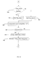
- FIGS. 5A-5C illustrate a flow chart 500 describing process operations performed by controller 155 according to one embodiment of the present invention.
- the process operations begin in FIG. 5A at 502 where the central processor associated with controller 155 and software implementing portions of the various embodiments of the present invention are booted.
- variables associated with various calculations and diagnostics are initialized.
- input variables are classified as measured variables, valve command variables (hydraulic fluid consuming device variables) and user-supplied variables.
- the measured variables include Pnow.
- Valve commands may include CVM (i.e., consume or do not consume hydraulic fluid).
- User-supplied variables may include Pfloor, Preg, Ptrigger, MaxTime which indicates the maximum length of time for an event to occur, dt which is a time step for performing an integration, ⁇ motor (Pelect) which is the efficiency of motor 115 and ⁇ pump which is the efficiency of pump unit 110.
- the output variables may be classified as dynamic output and output storage array of previous events that are stored on a hard drive or random access memory (RAM) of controller 155.
- the dynamic output variables may include valve demand, components associated with the valve demand, event number (event#), event timer variable for valve (Timer_CVM,) event timer variable for process (Timer_Event,) current volume of fluid (Vfluid) that is going to be integrated and a maximum time alarm (MaxTime_Alarm).
- the output storage array of previous event variables may include Vfluid, Timer_CVM, Timer_Event, Pmax (maximum power), Component and Demand.
- variables are used during the process to arrive at the calculated outputs. Some of these variables may include IntSW, Int_Reset, Pmax, and Pmech. Other variables may include IntSW_Old, L52_Old and Vfluid_Old. The details of these variables are explained below in more detail as they appear in the process operations described in FIGS. 5A-5C .
- the instantaneous power reading from wattmeter 150, Pnow is evaluated and compared at 506 to a trigger power level Ptrig to determine if there is an event.
- This trigger may be provided by a user, or statistically established from the floor power Pfloor (e.g., its mean + 3 standard deviations). If Pnow is greater than the trigger, Ptrig, either a flow event started or was already in process.
- the integrator switch variable IntSW is 1 for an event and 0 as shown at 510 if there is no event.
- the decision at 512 includes determining if the integration switch IntSW_Old equals 0 and the current integration switch IntSW equals 1. If the old value of integrator switch (IntSW_Old) is 0 and the current value of integration switch IntSW is 1, then an event has just begun and requires initialization. Otherwise the initialization associated with process operations 514 and 516 are bypassed and flow chart 500 continues to program string A in FIG. 5B .
- controller 155 If controller 155 confirms that an event has begun at 512, then the integration reset variable Int_Reset is set to 1 and the integration old switch variable IntSW_Old is set to 1 at 514. Essentially, controller 155 is getting ready for the data processing operations associated with a new event. In particular, controller 155 gets ready for the data processing operations associated with the new event at 516 by preparing the start new event statistic variables. In one embodiment, preparing the start new event statistic variables includes setting Event# equal to Event#+1, setting Timer_CVM equal to 0, setting Timer_Event equal to 0 and setting Pmax equal to Ptrig.
- controller 155 implements equation 9 at 518 to determine the net flow rate in excess of leakage, friction and windage.
- a decision is made as to whether the integration reset variable Int_Reset is equal to 0. Checking that the integration reset variable Int_Reset is equal to 0 ensures that controller 155 is considering a new event. If controller 155 determines at 520 that the integration reset variable Int_Reset is equal to 0, then it continues with integration of the flow rate at 522 to obtain the volumetric flow rate. On the other hand, if controller 155 determines at 520 that Int_Reset is not equal to 0, then it needs to set the fluid volume variable Vfluid_Old to 0 and the integration reset variable Int_Reset to 0 at 524.
- controller 155 performs the integration of the flow rate to obtain the volumetric flow rate.
- controller 155 may utilize a simple first-order Euler integration method to obtain the volumetric flow rate. Those skilled in the art will recognize that this is only one approach and that there are several other methods available to perform the integration.
- controller 155 updates the old fluid volume variable Vfluid_Old by Vfluid to continue the integral in the next step, if required.
- the timer associated with controller 155 is incremented by the time step dt.
- controller 155 determines at 530 if Pnow is greater than Pmax. If true, controller 155 sets Pmax equal to Pnow at 532. If false, the logic bypasses 532 and continues to another decision at 534. In particular, it is determined whether the integration switch variable IntSW equals 0 and the old integration switch variable IntSW_Old equals 1. Essentially, controller 155 is determining at 534 whether the sudden drop of Pnow to below Ptrig signals an end of an event. If it is determined to be false at 534 then the process operation bypasses processing block 536, and continues to programming string B.
- controller 155 continues with the aspect of determining diagnostics for hydraulic pump unit 105 and hydraulic fluid consuming device 200.
- controller 155 is interested in determining whether the event has taken too long to end. For example, Pfloor may have risen above Ptrigger which is causing the delay in the event to end.
- controller 155 determines at 538 whether the timer event variable Timer_Event is greater than the specified maximum time MaxTime. If the time has been exceeded, then an alarm variable is set to 1 at 540 in order to notify an operator. On the other hand, if the time has not been exceeded, then an alarm variable is maintained at a current state of 0 as indicated at 542 and the operator is not notified.
- controller determines at 546 whether the Components value is greater than 0. If the Components values is greater than 0, then the timer variable Timer_CVM is set to Timer_CVM+dt at 548 in order to track the amount of time that the valve or valves demanded hydraulic fluid from hydraulic pump unit 105. This value forms the numerator of the variable Demand, which expresses the ratio of the time the valve(s) demanded fluid to the time that it took hydraulic pump unit 105 to complete the event. This Demand variable value is computed at 550. Note that this determination is also made if it is determined at 546 that the Components value is 0. Basically, this Demand variable value provides an indication if pump unit 110 was still running without any demands for fluid from a valve or valves.
- controller 155 can be placed in storage and retrieved for subsequent analysis. For example, a plot of power and energy versus time can be obtained from the stored data and used by operators to understand the health of hydraulic pump unit 105 and hydraulic fluid consuming device 200.
- the data captured during the event may be presented to an operator located at a remote computing system where controller 155 may be deployed or to an operator located proximate hydraulic pump unit 105 and hydraulic fluid consuming device 200 via a computing device such as a portable human interface machine.
- FIG. 6 shows a raw data power screen display 600 and FIG. 7 shows a post-processed volume rate and volume displaced screen display 700.
- FIGS. 6-7 are only examples of what a possible display may look like and are not meant to limit the various embodiments of the present invention.
- Both screen display 600 and screen display 700 show a variable Combined that may be utilized to indicate what is or what is not triggering an event.
- process operation 550 continues from process operation 550 to program string C which goes back to FIG. 5A at the portion after the booting of controller 155 and initialization of the various process variables.
- FIGS. 5A-5C shows some of the processing functions associated with using controller 155 to compute various hydraulic fluid parameter computations and diagnostic.
- each block represents a process act associated with performing these functions.
- the acts noted in the blocks may occur out of the order noted in the figures or, for example, may in fact be executed substantially concurrently or in the reverse order, depending upon the act involved.
- additional blocks that describe the processing functions may be added.
- controller 155 portions of the actions performed by controller 155 can be implemented in the form of an entirely hardware embodiment, an entirely software embodiment or an embodiment containing both hardware and software elements.
- the processing functions performed by controller 155 may be implemented in software, which includes but is not limited to firmware, resident software, microcode, etc.
- the processing functions performed by controller 155 may be implemented in a control system such as the MARKTM VIe control system offered by GE Energy.
- controller 155 can take the form of a computer program product accessible from a computer-usable or computer-readable medium providing program code for use by or in connection with a computer or any instruction execution system (e.g., processing units).
- a computer-usable or computer readable medium can be any computer readable storage medium that can contain or store the program for use by or in connection with the computer or instruction execution system.
- the computer readable medium can be an electronic, magnetic, optical, electromagnetic, infrared, or semiconductor system (or apparatus or device).
- Examples of a computer-readable medium include a semiconductor or solid state memory, a random access memory (RAM), a read-only memory (ROM), a rigid magnetic disk and an optical disk.
- Current examples of optical disks include a compact disk - read only memory (CD-ROM), a compact disk - read/write (CD-R/W) and a digital video disc (DVD).
Landscapes
- Physics & Mathematics (AREA)
- Fluid Mechanics (AREA)
- General Physics & Mathematics (AREA)
- Fluid-Pressure Circuits (AREA)
- Control Of Transmission Device (AREA)
Applications Claiming Priority (1)
| Application Number | Priority Date | Filing Date | Title |
|---|---|---|---|
| US13/069,902 US8812264B2 (en) | 2011-03-23 | 2011-03-23 | Use of wattmeter to determine hydraulic fluid parameters |
Publications (3)
| Publication Number | Publication Date |
|---|---|
| EP2518455A2 true EP2518455A2 (de) | 2012-10-31 |
| EP2518455A3 EP2518455A3 (de) | 2014-07-02 |
| EP2518455B1 EP2518455B1 (de) | 2019-06-12 |
Family
ID=45936818
Family Applications (1)
| Application Number | Title | Priority Date | Filing Date |
|---|---|---|---|
| EP12160038.1A Active EP2518455B1 (de) | 2011-03-23 | 2012-03-19 | Verwendung eines Wattmeters zur Bestimmung von Hydraulikflüssigkeitsparametern |
Country Status (3)
| Country | Link |
|---|---|
| US (1) | US8812264B2 (de) |
| EP (1) | EP2518455B1 (de) |
| CN (1) | CN102691696B (de) |
Families Citing this family (5)
| Publication number | Priority date | Publication date | Assignee | Title |
|---|---|---|---|---|
| US9091262B2 (en) * | 2011-05-27 | 2015-07-28 | General Electric Company | Use of wattmeter to obtain diagnostics of hydraulic system during transient-state start-up operation |
| DE102013006220B4 (de) * | 2013-04-11 | 2022-08-18 | Bürkert Werke GmbH | Pneumatischer Antrieb und Verfahren zur Erfassung der Leistung eines pneumatischen Antriebs |
| US9691023B2 (en) | 2014-11-30 | 2017-06-27 | WiseWear Corporation | Exercise behavior prediction |
| EP3236328B8 (de) * | 2016-04-21 | 2019-03-06 | Kaeser Kompressoren SE | Verfahren zur analyse der druckluftversorgungssicherheit einer druckluftanlage |
| US11168463B2 (en) * | 2017-09-07 | 2021-11-09 | Deere & Company | Hydrostatic transmission pedal stroke limiter |
Family Cites Families (20)
| Publication number | Priority date | Publication date | Assignee | Title |
|---|---|---|---|---|
| US4108574A (en) | 1977-01-21 | 1978-08-22 | International Paper Company | Apparatus and method for the indirect measurement and control of the flow rate of a liquid in a piping system |
| US4278403A (en) | 1979-09-06 | 1981-07-14 | Shafer Jon L | Control for hydraulic accumulator system |
| US5318409A (en) | 1993-03-23 | 1994-06-07 | Westinghouse Electric Corp. | Rod pump flow rate determination from motor power |
| US5353646A (en) | 1994-01-10 | 1994-10-11 | Atlantic Richfield Company | Multiphase fluid flow measurement |
| AU5311496A (en) | 1995-03-14 | 1996-10-02 | Boeing Company, The | Aircraft hydraulic pump control system |
| GB9609593D0 (en) | 1996-05-08 | 1996-07-10 | Advanced Energy Monitor Syst | Pumps |
| US5778671A (en) * | 1996-09-13 | 1998-07-14 | Vickers, Inc. | Electrohydraulic system and apparatus with bidirectional electric-motor/hydraulic-pump unit |
| JP3723866B2 (ja) | 2001-02-07 | 2005-12-07 | 株式会社日立製作所 | インターナルポンプの性能監視方法及び装置 |
| US8914300B2 (en) * | 2001-08-10 | 2014-12-16 | Rockwell Automation Technologies, Inc. | System and method for dynamic multi-objective optimization of machine selection, integration and utilization |
| SE0103371D0 (sv) | 2001-10-09 | 2001-10-09 | Abb Ab | Flow measurements |
| US7117120B2 (en) | 2002-09-27 | 2006-10-03 | Unico, Inc. | Control system for centrifugal pumps |
| WO2005026922A1 (en) | 2003-09-15 | 2005-03-24 | Du Plessis Francois Jacobus | Method and apparatus for determining the approximate flow rate of a fluid through a pump |
| FI20040351L (fi) | 2004-03-04 | 2005-09-05 | Abb Oy | Mittausmenetelmä ja -järjestely |
| KR100559296B1 (ko) * | 2004-03-22 | 2006-03-15 | 볼보 컨스트럭션 이키프먼트 홀딩 스웨덴 에이비 | 유압실린더의 진동 제어방법 |
| JP5035866B2 (ja) * | 2005-10-04 | 2012-09-26 | ヤンマー株式会社 | 作業車両における動力伝達装置 |
| US7730705B2 (en) * | 2007-04-20 | 2010-06-08 | Parker-Hannifin Corporation | Electro-hydraulic lift mechanism for lawn mower deck |
| US9360017B2 (en) | 2009-01-23 | 2016-06-07 | Grundfos Pumps Corporation | Pump assembly having an integrated user interface |
| US8571798B2 (en) * | 2009-03-03 | 2013-10-29 | Baker Hughes Incorporated | System and method for monitoring fluid flow through an electrical submersible pump |
| US8109069B2 (en) | 2009-04-30 | 2012-02-07 | The Toro Company | Proportional counterbalance system for mower cutting units |
| US8096128B2 (en) | 2009-09-17 | 2012-01-17 | Echogen Power Systems | Heat engine and heat to electricity systems and methods |
-
2011
- 2011-03-23 US US13/069,902 patent/US8812264B2/en active Active
-
2012
- 2012-03-19 EP EP12160038.1A patent/EP2518455B1/de active Active
- 2012-03-23 CN CN201210093472.7A patent/CN102691696B/zh not_active Expired - Fee Related
Non-Patent Citations (1)
| Title |
|---|
| None |
Also Published As
| Publication number | Publication date |
|---|---|
| US8812264B2 (en) | 2014-08-19 |
| CN102691696A (zh) | 2012-09-26 |
| EP2518455B1 (de) | 2019-06-12 |
| US20120245894A1 (en) | 2012-09-27 |
| EP2518455A3 (de) | 2014-07-02 |
| CN102691696B (zh) | 2016-08-31 |
Similar Documents
| Publication | Publication Date | Title |
|---|---|---|
| EP2518455B1 (de) | Verwendung eines Wattmeters zur Bestimmung von Hydraulikflüssigkeitsparametern | |
| EP2744980B1 (de) | Bestimmung von strömungsniveaus in einem exzenterschneckenpumpsystem | |
| US9638194B2 (en) | System and method for power management of pumping system | |
| US20160195082A1 (en) | System and method for health management of pumping system | |
| US9091262B2 (en) | Use of wattmeter to obtain diagnostics of hydraulic system during transient-state start-up operation | |
| US20080243287A1 (en) | Methods and Apparatuses for Monitoring Steam Turbine Valve Assemblies | |
| EP2027513B1 (de) | Diagnose in prozessteuer- und überwachungssystemen | |
| US20230407863A1 (en) | Pump monitoring system and method | |
| CN102016331A (zh) | 尤其用于航空器的蓄能器状态的控制方法 | |
| KR101258017B1 (ko) | 펌프 성능 진단 장치 | |
| KR20230043585A (ko) | 펌프장 모니터링 장치 및 방법 | |
| Liniger et al. | Reliable fluid power pitch systems: A review of state of the art for design and reliability evaluation of fluid power systems | |
| US20150159646A1 (en) | Sensorless disturbance detection in metering pumps with stepping motor | |
| EP3184731B1 (de) | Verfahren zur überwachung eines bohrlochs oder einer bohrlochleistung und system | |
| WO2016043866A1 (en) | Centrifugal pump degradation monitoring without flow rate measurement | |
| US20220228473A1 (en) | Sucker rod pump automated control method and system | |
| DK178505B1 (en) | Model based wind turbine component monitoring | |
| CN117769627A (zh) | 状态监控系统 | |
| CA3019648C (en) | Method for analyzing the compressed-air supply security of a compressed-air system | |
| JP2021173163A (ja) | アキュムレータの異常診断方法及びアキュムレータの異常診断システム | |
| CA2990516C (en) | Determining the phase composition of a fluid flow | |
| JP2019135962A (ja) | 食品加工管理システム | |
| Mones | Investigation of dynamic responses of on-rotor wireless sensors for condition monitoring of rotating machines |
Legal Events
| Date | Code | Title | Description |
|---|---|---|---|
| PUAI | Public reference made under article 153(3) epc to a published international application that has entered the european phase |
Free format text: ORIGINAL CODE: 0009012 |
|
| AK | Designated contracting states |
Kind code of ref document: A2 Designated state(s): AL AT BE BG CH CY CZ DE DK EE ES FI FR GB GR HR HU IE IS IT LI LT LU LV MC MK MT NL NO PL PT RO RS SE SI SK SM TR |
|
| AX | Request for extension of the european patent |
Extension state: BA ME |
|
| RIC1 | Information provided on ipc code assigned before grant |
Ipc: G01F 1/86 20060101ALI20140417BHEP Ipc: G01F 15/06 20060101ALI20140417BHEP Ipc: G01F 1/80 20060101AFI20140417BHEP |
|
| RIC1 | Information provided on ipc code assigned before grant |
Ipc: G01F 1/80 20060101AFI20140423BHEP Ipc: G01F 1/86 20060101ALI20140423BHEP Ipc: G01F 15/06 20060101ALI20140423BHEP |
|
| PUAL | Search report despatched |
Free format text: ORIGINAL CODE: 0009013 |
|
| AK | Designated contracting states |
Kind code of ref document: A3 Designated state(s): AL AT BE BG CH CY CZ DE DK EE ES FI FR GB GR HR HU IE IS IT LI LT LU LV MC MK MT NL NO PL PT RO RS SE SI SK SM TR |
|
| AX | Request for extension of the european patent |
Extension state: BA ME |
|
| RIC1 | Information provided on ipc code assigned before grant |
Ipc: G01F 1/86 20060101ALI20140526BHEP Ipc: G01F 15/06 20060101ALI20140526BHEP Ipc: G01F 1/80 20060101AFI20140526BHEP |
|
| 17P | Request for examination filed |
Effective date: 20150105 |
|
| RBV | Designated contracting states (corrected) |
Designated state(s): AL AT BE BG CH CY CZ DE DK EE ES FI FR GB GR HR HU IE IS IT LI LT LU LV MC MK MT NL NO PL PT RO RS SE SI SK SM TR |
|
| 17Q | First examination report despatched |
Effective date: 20160303 |
|
| STAA | Information on the status of an ep patent application or granted ep patent |
Free format text: STATUS: EXAMINATION IS IN PROGRESS |
|
| GRAP | Despatch of communication of intention to grant a patent |
Free format text: ORIGINAL CODE: EPIDOSNIGR1 |
|
| STAA | Information on the status of an ep patent application or granted ep patent |
Free format text: STATUS: GRANT OF PATENT IS INTENDED |
|
| INTG | Intention to grant announced |
Effective date: 20190108 |
|
| GRAS | Grant fee paid |
Free format text: ORIGINAL CODE: EPIDOSNIGR3 |
|
| GRAA | (expected) grant |
Free format text: ORIGINAL CODE: 0009210 |
|
| STAA | Information on the status of an ep patent application or granted ep patent |
Free format text: STATUS: THE PATENT HAS BEEN GRANTED |
|
| AK | Designated contracting states |
Kind code of ref document: B1 Designated state(s): AL AT BE BG CH CY CZ DE DK EE ES FI FR GB GR HR HU IE IS IT LI LT LU LV MC MK MT NL NO PL PT RO RS SE SI SK SM TR |
|
| REG | Reference to a national code |
Ref country code: GB Ref legal event code: FG4D |
|
| REG | Reference to a national code |
Ref country code: CH Ref legal event code: EP |
|
| REG | Reference to a national code |
Ref country code: AT Ref legal event code: REF Ref document number: 1143161 Country of ref document: AT Kind code of ref document: T Effective date: 20190615 |
|
| REG | Reference to a national code |
Ref country code: DE Ref legal event code: R096 Ref document number: 602012060840 Country of ref document: DE |
|
| REG | Reference to a national code |
Ref country code: IE Ref legal event code: FG4D |
|
| REG | Reference to a national code |
Ref country code: NL Ref legal event code: MP Effective date: 20190612 |
|
| REG | Reference to a national code |
Ref country code: LT Ref legal event code: MG4D |
|
| PG25 | Lapsed in a contracting state [announced via postgrant information from national office to epo] |
Ref country code: ES Free format text: LAPSE BECAUSE OF FAILURE TO SUBMIT A TRANSLATION OF THE DESCRIPTION OR TO PAY THE FEE WITHIN THE PRESCRIBED TIME-LIMIT Effective date: 20190612 Ref country code: AL Free format text: LAPSE BECAUSE OF FAILURE TO SUBMIT A TRANSLATION OF THE DESCRIPTION OR TO PAY THE FEE WITHIN THE PRESCRIBED TIME-LIMIT Effective date: 20190612 Ref country code: FI Free format text: LAPSE BECAUSE OF FAILURE TO SUBMIT A TRANSLATION OF THE DESCRIPTION OR TO PAY THE FEE WITHIN THE PRESCRIBED TIME-LIMIT Effective date: 20190612 Ref country code: LT Free format text: LAPSE BECAUSE OF FAILURE TO SUBMIT A TRANSLATION OF THE DESCRIPTION OR TO PAY THE FEE WITHIN THE PRESCRIBED TIME-LIMIT Effective date: 20190612 Ref country code: HR Free format text: LAPSE BECAUSE OF FAILURE TO SUBMIT A TRANSLATION OF THE DESCRIPTION OR TO PAY THE FEE WITHIN THE PRESCRIBED TIME-LIMIT Effective date: 20190612 Ref country code: SE Free format text: LAPSE BECAUSE OF FAILURE TO SUBMIT A TRANSLATION OF THE DESCRIPTION OR TO PAY THE FEE WITHIN THE PRESCRIBED TIME-LIMIT Effective date: 20190612 Ref country code: NO Free format text: LAPSE BECAUSE OF FAILURE TO SUBMIT A TRANSLATION OF THE DESCRIPTION OR TO PAY THE FEE WITHIN THE PRESCRIBED TIME-LIMIT Effective date: 20190912 |
|
| PG25 | Lapsed in a contracting state [announced via postgrant information from national office to epo] |
Ref country code: RS Free format text: LAPSE BECAUSE OF FAILURE TO SUBMIT A TRANSLATION OF THE DESCRIPTION OR TO PAY THE FEE WITHIN THE PRESCRIBED TIME-LIMIT Effective date: 20190612 Ref country code: LV Free format text: LAPSE BECAUSE OF FAILURE TO SUBMIT A TRANSLATION OF THE DESCRIPTION OR TO PAY THE FEE WITHIN THE PRESCRIBED TIME-LIMIT Effective date: 20190612 Ref country code: GR Free format text: LAPSE BECAUSE OF FAILURE TO SUBMIT A TRANSLATION OF THE DESCRIPTION OR TO PAY THE FEE WITHIN THE PRESCRIBED TIME-LIMIT Effective date: 20190913 Ref country code: BG Free format text: LAPSE BECAUSE OF FAILURE TO SUBMIT A TRANSLATION OF THE DESCRIPTION OR TO PAY THE FEE WITHIN THE PRESCRIBED TIME-LIMIT Effective date: 20190912 |
|
| REG | Reference to a national code |
Ref country code: AT Ref legal event code: MK05 Ref document number: 1143161 Country of ref document: AT Kind code of ref document: T Effective date: 20190612 |
|
| PG25 | Lapsed in a contracting state [announced via postgrant information from national office to epo] |
Ref country code: AT Free format text: LAPSE BECAUSE OF FAILURE TO SUBMIT A TRANSLATION OF THE DESCRIPTION OR TO PAY THE FEE WITHIN THE PRESCRIBED TIME-LIMIT Effective date: 20190612 Ref country code: PT Free format text: LAPSE BECAUSE OF FAILURE TO SUBMIT A TRANSLATION OF THE DESCRIPTION OR TO PAY THE FEE WITHIN THE PRESCRIBED TIME-LIMIT Effective date: 20191014 Ref country code: NL Free format text: LAPSE BECAUSE OF FAILURE TO SUBMIT A TRANSLATION OF THE DESCRIPTION OR TO PAY THE FEE WITHIN THE PRESCRIBED TIME-LIMIT Effective date: 20190612 Ref country code: CZ Free format text: LAPSE BECAUSE OF FAILURE TO SUBMIT A TRANSLATION OF THE DESCRIPTION OR TO PAY THE FEE WITHIN THE PRESCRIBED TIME-LIMIT Effective date: 20190612 Ref country code: SK Free format text: LAPSE BECAUSE OF FAILURE TO SUBMIT A TRANSLATION OF THE DESCRIPTION OR TO PAY THE FEE WITHIN THE PRESCRIBED TIME-LIMIT Effective date: 20190612 Ref country code: RO Free format text: LAPSE BECAUSE OF FAILURE TO SUBMIT A TRANSLATION OF THE DESCRIPTION OR TO PAY THE FEE WITHIN THE PRESCRIBED TIME-LIMIT Effective date: 20190612 Ref country code: EE Free format text: LAPSE BECAUSE OF FAILURE TO SUBMIT A TRANSLATION OF THE DESCRIPTION OR TO PAY THE FEE WITHIN THE PRESCRIBED TIME-LIMIT Effective date: 20190612 |
|
| PG25 | Lapsed in a contracting state [announced via postgrant information from national office to epo] |
Ref country code: IS Free format text: LAPSE BECAUSE OF FAILURE TO SUBMIT A TRANSLATION OF THE DESCRIPTION OR TO PAY THE FEE WITHIN THE PRESCRIBED TIME-LIMIT Effective date: 20191012 Ref country code: SM Free format text: LAPSE BECAUSE OF FAILURE TO SUBMIT A TRANSLATION OF THE DESCRIPTION OR TO PAY THE FEE WITHIN THE PRESCRIBED TIME-LIMIT Effective date: 20190612 Ref country code: IT Free format text: LAPSE BECAUSE OF FAILURE TO SUBMIT A TRANSLATION OF THE DESCRIPTION OR TO PAY THE FEE WITHIN THE PRESCRIBED TIME-LIMIT Effective date: 20190612 |
|
| REG | Reference to a national code |
Ref country code: DE Ref legal event code: R097 Ref document number: 602012060840 Country of ref document: DE |
|
| PG25 | Lapsed in a contracting state [announced via postgrant information from national office to epo] |
Ref country code: TR Free format text: LAPSE BECAUSE OF FAILURE TO SUBMIT A TRANSLATION OF THE DESCRIPTION OR TO PAY THE FEE WITHIN THE PRESCRIBED TIME-LIMIT Effective date: 20190612 |
|
| PLBE | No opposition filed within time limit |
Free format text: ORIGINAL CODE: 0009261 |
|
| STAA | Information on the status of an ep patent application or granted ep patent |
Free format text: STATUS: NO OPPOSITION FILED WITHIN TIME LIMIT |
|
| PG25 | Lapsed in a contracting state [announced via postgrant information from national office to epo] |
Ref country code: DK Free format text: LAPSE BECAUSE OF FAILURE TO SUBMIT A TRANSLATION OF THE DESCRIPTION OR TO PAY THE FEE WITHIN THE PRESCRIBED TIME-LIMIT Effective date: 20190612 Ref country code: PL Free format text: LAPSE BECAUSE OF FAILURE TO SUBMIT A TRANSLATION OF THE DESCRIPTION OR TO PAY THE FEE WITHIN THE PRESCRIBED TIME-LIMIT Effective date: 20190612 |
|
| 26N | No opposition filed |
Effective date: 20200313 |
|
| PG25 | Lapsed in a contracting state [announced via postgrant information from national office to epo] |
Ref country code: SI Free format text: LAPSE BECAUSE OF FAILURE TO SUBMIT A TRANSLATION OF THE DESCRIPTION OR TO PAY THE FEE WITHIN THE PRESCRIBED TIME-LIMIT Effective date: 20190612 Ref country code: IS Free format text: LAPSE BECAUSE OF FAILURE TO SUBMIT A TRANSLATION OF THE DESCRIPTION OR TO PAY THE FEE WITHIN THE PRESCRIBED TIME-LIMIT Effective date: 20200224 |
|
| PG2D | Information on lapse in contracting state deleted |
Ref country code: IS |
|
| PG25 | Lapsed in a contracting state [announced via postgrant information from national office to epo] |
Ref country code: MC Free format text: LAPSE BECAUSE OF FAILURE TO SUBMIT A TRANSLATION OF THE DESCRIPTION OR TO PAY THE FEE WITHIN THE PRESCRIBED TIME-LIMIT Effective date: 20190612 |
|
| REG | Reference to a national code |
Ref country code: BE Ref legal event code: MM Effective date: 20200331 |
|
| PG25 | Lapsed in a contracting state [announced via postgrant information from national office to epo] |
Ref country code: LU Free format text: LAPSE BECAUSE OF NON-PAYMENT OF DUE FEES Effective date: 20200319 |
|
| PG25 | Lapsed in a contracting state [announced via postgrant information from national office to epo] |
Ref country code: IE Free format text: LAPSE BECAUSE OF NON-PAYMENT OF DUE FEES Effective date: 20200319 |
|
| PG25 | Lapsed in a contracting state [announced via postgrant information from national office to epo] |
Ref country code: BE Free format text: LAPSE BECAUSE OF NON-PAYMENT OF DUE FEES Effective date: 20200331 |
|
| PGFP | Annual fee paid to national office [announced via postgrant information from national office to epo] |
Ref country code: GB Payment date: 20220225 Year of fee payment: 11 Ref country code: DE Payment date: 20220217 Year of fee payment: 11 Ref country code: CH Payment date: 20220218 Year of fee payment: 11 |
|
| PG25 | Lapsed in a contracting state [announced via postgrant information from national office to epo] |
Ref country code: MT Free format text: LAPSE BECAUSE OF FAILURE TO SUBMIT A TRANSLATION OF THE DESCRIPTION OR TO PAY THE FEE WITHIN THE PRESCRIBED TIME-LIMIT Effective date: 20190612 Ref country code: CY Free format text: LAPSE BECAUSE OF FAILURE TO SUBMIT A TRANSLATION OF THE DESCRIPTION OR TO PAY THE FEE WITHIN THE PRESCRIBED TIME-LIMIT Effective date: 20190612 |
|
| PGFP | Annual fee paid to national office [announced via postgrant information from national office to epo] |
Ref country code: FR Payment date: 20220218 Year of fee payment: 11 |
|
| PG25 | Lapsed in a contracting state [announced via postgrant information from national office to epo] |
Ref country code: MK Free format text: LAPSE BECAUSE OF FAILURE TO SUBMIT A TRANSLATION OF THE DESCRIPTION OR TO PAY THE FEE WITHIN THE PRESCRIBED TIME-LIMIT Effective date: 20190612 |
|
| REG | Reference to a national code |
Ref country code: DE Ref legal event code: R119 Ref document number: 602012060840 Country of ref document: DE |
|
| REG | Reference to a national code |
Ref country code: CH Ref legal event code: PL |
|
| GBPC | Gb: european patent ceased through non-payment of renewal fee |
Effective date: 20230319 |
|
| PG25 | Lapsed in a contracting state [announced via postgrant information from national office to epo] |
Ref country code: GB Free format text: LAPSE BECAUSE OF NON-PAYMENT OF DUE FEES Effective date: 20230319 |
|
| PG25 | Lapsed in a contracting state [announced via postgrant information from national office to epo] |
Ref country code: LI Free format text: LAPSE BECAUSE OF NON-PAYMENT OF DUE FEES Effective date: 20230331 Ref country code: GB Free format text: LAPSE BECAUSE OF NON-PAYMENT OF DUE FEES Effective date: 20230319 Ref country code: FR Free format text: LAPSE BECAUSE OF NON-PAYMENT OF DUE FEES Effective date: 20230331 Ref country code: DE Free format text: LAPSE BECAUSE OF NON-PAYMENT OF DUE FEES Effective date: 20231003 Ref country code: CH Free format text: LAPSE BECAUSE OF NON-PAYMENT OF DUE FEES Effective date: 20230331 |