EP2518354A1 - Needle bearing - Google Patents
Needle bearing Download PDFInfo
- Publication number
- EP2518354A1 EP2518354A1 EP10809222A EP10809222A EP2518354A1 EP 2518354 A1 EP2518354 A1 EP 2518354A1 EP 10809222 A EP10809222 A EP 10809222A EP 10809222 A EP10809222 A EP 10809222A EP 2518354 A1 EP2518354 A1 EP 2518354A1
- Authority
- EP
- European Patent Office
- Prior art keywords
- elastic deformation
- portions
- cage
- needle bearing
- pair
- Prior art date
- Legal status (The legal status is an assumption and is not a legal conclusion. Google has not performed a legal analysis and makes no representation as to the accuracy of the status listed.)
- Granted
Links
Images




Classifications
-
- F—MECHANICAL ENGINEERING; LIGHTING; HEATING; WEAPONS; BLASTING
- F16—ENGINEERING ELEMENTS AND UNITS; GENERAL MEASURES FOR PRODUCING AND MAINTAINING EFFECTIVE FUNCTIONING OF MACHINES OR INSTALLATIONS; THERMAL INSULATION IN GENERAL
- F16C—SHAFTS; FLEXIBLE SHAFTS; ELEMENTS OR CRANKSHAFT MECHANISMS; ROTARY BODIES OTHER THAN GEARING ELEMENTS; BEARINGS
- F16C33/00—Parts of bearings; Special methods for making bearings or parts thereof
- F16C33/30—Parts of ball or roller bearings
- F16C33/46—Cages for rollers or needles
- F16C33/48—Cages for rollers or needles for multiple rows of rollers or needles
-
- F—MECHANICAL ENGINEERING; LIGHTING; HEATING; WEAPONS; BLASTING
- F16—ENGINEERING ELEMENTS AND UNITS; GENERAL MEASURES FOR PRODUCING AND MAINTAINING EFFECTIVE FUNCTIONING OF MACHINES OR INSTALLATIONS; THERMAL INSULATION IN GENERAL
- F16C—SHAFTS; FLEXIBLE SHAFTS; ELEMENTS OR CRANKSHAFT MECHANISMS; ROTARY BODIES OTHER THAN GEARING ELEMENTS; BEARINGS
- F16C33/00—Parts of bearings; Special methods for making bearings or parts thereof
- F16C33/30—Parts of ball or roller bearings
- F16C33/46—Cages for rollers or needles
- F16C33/4694—Single-split roller or needle cages
-
- F—MECHANICAL ENGINEERING; LIGHTING; HEATING; WEAPONS; BLASTING
- F16—ENGINEERING ELEMENTS AND UNITS; GENERAL MEASURES FOR PRODUCING AND MAINTAINING EFFECTIVE FUNCTIONING OF MACHINES OR INSTALLATIONS; THERMAL INSULATION IN GENERAL
- F16C—SHAFTS; FLEXIBLE SHAFTS; ELEMENTS OR CRANKSHAFT MECHANISMS; ROTARY BODIES OTHER THAN GEARING ELEMENTS; BEARINGS
- F16C19/00—Bearings with rolling contact, for exclusively rotary movement
- F16C19/22—Bearings with rolling contact, for exclusively rotary movement with bearing rollers essentially of the same size in one or more circular rows, e.g. needle bearings
- F16C19/44—Needle bearings
- F16C19/46—Needle bearings with one row or needles
- F16C19/466—Needle bearings with one row or needles comprising needle rollers and an outer ring, i.e. subunit without inner ring
-
- F—MECHANICAL ENGINEERING; LIGHTING; HEATING; WEAPONS; BLASTING
- F16—ENGINEERING ELEMENTS AND UNITS; GENERAL MEASURES FOR PRODUCING AND MAINTAINING EFFECTIVE FUNCTIONING OF MACHINES OR INSTALLATIONS; THERMAL INSULATION IN GENERAL
- F16C—SHAFTS; FLEXIBLE SHAFTS; ELEMENTS OR CRANKSHAFT MECHANISMS; ROTARY BODIES OTHER THAN GEARING ELEMENTS; BEARINGS
- F16C33/00—Parts of bearings; Special methods for making bearings or parts thereof
- F16C33/30—Parts of ball or roller bearings
- F16C33/46—Cages for rollers or needles
- F16C33/4617—Massive or moulded cages having cage pockets surrounding the rollers, e.g. machined window cages
- F16C33/4623—Massive or moulded cages having cage pockets surrounding the rollers, e.g. machined window cages formed as one-piece cages, i.e. monoblock cages
- F16C33/4635—Massive or moulded cages having cage pockets surrounding the rollers, e.g. machined window cages formed as one-piece cages, i.e. monoblock cages made from plastic, e.g. injection moulded window cages
-
- F—MECHANICAL ENGINEERING; LIGHTING; HEATING; WEAPONS; BLASTING
- F16—ENGINEERING ELEMENTS AND UNITS; GENERAL MEASURES FOR PRODUCING AND MAINTAINING EFFECTIVE FUNCTIONING OF MACHINES OR INSTALLATIONS; THERMAL INSULATION IN GENERAL
- F16C—SHAFTS; FLEXIBLE SHAFTS; ELEMENTS OR CRANKSHAFT MECHANISMS; ROTARY BODIES OTHER THAN GEARING ELEMENTS; BEARINGS
- F16C33/00—Parts of bearings; Special methods for making bearings or parts thereof
- F16C33/30—Parts of ball or roller bearings
- F16C33/46—Cages for rollers or needles
- F16C33/54—Cages for rollers or needles made from wire, strips, or sheet metal
-
- F—MECHANICAL ENGINEERING; LIGHTING; HEATING; WEAPONS; BLASTING
- F16—ENGINEERING ELEMENTS AND UNITS; GENERAL MEASURES FOR PRODUCING AND MAINTAINING EFFECTIVE FUNCTIONING OF MACHINES OR INSTALLATIONS; THERMAL INSULATION IN GENERAL
- F16C—SHAFTS; FLEXIBLE SHAFTS; ELEMENTS OR CRANKSHAFT MECHANISMS; ROTARY BODIES OTHER THAN GEARING ELEMENTS; BEARINGS
- F16C39/00—Relieving load on bearings
- F16C39/02—Relieving load on bearings using mechanical means
-
- F—MECHANICAL ENGINEERING; LIGHTING; HEATING; WEAPONS; BLASTING
- F16—ENGINEERING ELEMENTS AND UNITS; GENERAL MEASURES FOR PRODUCING AND MAINTAINING EFFECTIVE FUNCTIONING OF MACHINES OR INSTALLATIONS; THERMAL INSULATION IN GENERAL
- F16C—SHAFTS; FLEXIBLE SHAFTS; ELEMENTS OR CRANKSHAFT MECHANISMS; ROTARY BODIES OTHER THAN GEARING ELEMENTS; BEARINGS
- F16C2361/00—Apparatus or articles in engineering in general
- F16C2361/61—Toothed gear systems, e.g. support of pinion shafts
Definitions
- the present invention relates to needle bearings, and in particular relates to needle bearings applied to an automobile drive system including an automatic transmission (AT), a manual transmission (MT), a differential gear, a transfer and a detent, an engine crankshaft support, an engine camshaft support, and an automobile steering system.
- AT automatic transmission
- MT manual transmission
- a differential gear differential gear
- transfer and a detent an engine crankshaft support
- engine camshaft support an automobile steering system
- a drawn cup needle bearing 100 includes: a drawn cup outer ring 101 having, at its inner peripheral surface, a raceway surface 101a and having, at its end portions, a pair of flanges 101b, 101c; a plurality of needles 102 placed inside the drawn cup outer ring 101 so as to be rolled along the raceway surface 101a; and a cage 103 having a plurality of pockets for holding the plurality of needles 102.
- the present invention has been made in view of the above-described circumstances, and an object of the present invention is to provide a needle bearing having a circumferentially shrinkable or extensible cage capable of preventing plastic deformation and capable of ensuring both of a sufficient strength for axial torsion and a sufficient deformation amount.
- a relationship among an outer peripheral length of the cage 15, a total sum of the circumferential distances L1 of the cuts 15c, and an inner peripheral length of the inward flanges 11b, 11c of the drawn cup 11 is represented by the following expression: ⁇ ⁇ D ⁇ 1 - L ⁇ 1 ⁇ number of cuts ⁇ ⁇ ⁇ D ⁇ 2
- each elastic deformation portion 17 is formed between the circumferentially adjacent columns 16, 16, and the circumferential distance L1 of the cut 15c is smaller than a total sum of the circumferential distances L2 between the adjacent columns 16 and elastic deformation pieces 17a; hence, when circumferential shrinkage is caused, the columns 16 and the elastic deformation pieces 17a will not come into contact with each other before the cuts 15c disappear, thus making it possible to ensure a sufficient deformation amount.
- an outer peripheral surface of the elastic deformation piece 17 of the elastic deformation portion 17 according to the first embodiment may be tapered so as to be gradually radially reduced in thickness from the end portions 15b of the arc-shaped portions 15 to an axial inward end portion of the elastic deformation piece 17a.
- the axial inward end portion of the elastic deformation piece 17a which serves as a free end side thereof, is deformed radially outward due to centrifugal force as indicated by imaginary lines of FIG. 9(b) , the axial inward end portion can be prevented from coming into contact with the raceway surface 11a of the drawn cup 11. Note that as illustrated in FIG.
- the outer ring drawn cup 11 having, at its inner peripheral surface, the raceway surface 11 a and having, at its end portions, the inward flanges 11b, 11c is used, but an inner ring drawn cup having, at its outer peripheral surface, a raceway surface and having, at its end portions, outward flanges may alternatively be used; in that case, the cage 13 is deformed so as to be circumferentially extended and is thus inserted into the drawn cup.
- a material for the cage is freely selected as long as it is elastically deformable, but a resin is preferably used; alternatively, a metal may be used, but it is more difficult for a metal to be elastically deformed than a resin, and therefore, the number of elastic deformation portions is set to be increased in that case.
- resins to be used for the cage include: polyamide (nylon resin) such as aromatic polyamide (aromatic PA), polyamide 46, polyamide 6 and polyamide 66; polyphenylene sulfide (PPS); polyether ether ketone (PEEK); polyacetal (POM); and a fluorine resin such as polytetrafluoroethylene (PTFE).
Landscapes
- Engineering & Computer Science (AREA)
- General Engineering & Computer Science (AREA)
- Mechanical Engineering (AREA)
- Rolling Contact Bearings (AREA)
Abstract
Description
- The present invention relates to needle bearings, and in particular relates to needle bearings applied to an automobile drive system including an automatic transmission (AT), a manual transmission (MT), a differential gear, a transfer and a detent, an engine crankshaft support, an engine camshaft support, and an automobile steering system.
- In an automatic transmission or the like of an automobile, instead of a slide bearing (bushing), a drawn cup needle bearing having a similar cross-sectional height has recently been used at a position where a radial load is received. As illustrated in
FIG. 10 , a drawn cup needle bearing 100 includes: a drawn cupouter ring 101 having, at its inner peripheral surface, araceway surface 101a and having, at its end portions, a pair offlanges needles 102 placed inside the drawn cupouter ring 101 so as to be rolled along theraceway surface 101a; and acage 103 having a plurality of pockets for holding the plurality ofneedles 102. - Methods for providing the foregoing drawn cup needle bearing include: a method in which a swaged portion serving as the
flange 101c of the drawn cupouter ring 101 is subjected to anti-carbuization, hardening is carried out by a process such as carburization or carbonitriding, and then theneedles 102 and thecage 103 are inserted to swage an end portion; and a method in which the drawn cupouter ring 101 is hardened by a process such as carburization or carbonitriding, and then theneedles 102 and thecage 103 are inserted to anneal a swaged portion by induction heating or the like and perform swaging thereon. Such methods further include the adoption of a method in which needles and a cage are built into a drawn cup outer ring and then heat treatments such as carbonitriding, quenching and tempering are carried out to perform processes such as the above-mentioned anti-carburization and induction heating on a swaged portion. - On the other hand, there has been proposed a method in which a cage having, at its circumferential part, a radially inwardly deformable portion is used, the cage is placed inside a drawn cup outer ring while being shrunk circumferentially by radially inwardly deforming the cage, and needles are attached to the placed cage, thereby fabricating a drawn cup needle bearing while avoiding the above-described complicated processes (see Patent Document 1, for example).
- Also in a radial needle bearing, as illustrated in
FIG. 11 , acage 200 is provided, at its one circumferential position, with anelastic connector 201 formed symmetrically with respect to an axial intermediate portion, and thiselastic connector 201 is circumferentially increased in diameter and thus placed beyond a flange (see Patent Document 2, for example). -
- Patent Document 1:
JP-A-2004-211825 - Patent Document 2:
JP-A-2008-8833 - Actually, when a cage thickness cannot be sufficiently ensured in the cage described in Patent Document 1, there occurs a problem that the cage causes plastic deformation and cannot successfully hold the needles. On the other hand, the cage described in Patent Document 2 is capable of ensuring a sufficient strength for axial torsion but might be incapable of obtaining a sufficient deformation amount for a radial dimension of the flange because an elastic deformation portion is provided at only one circumferential position. Furthermore, an object of this cage is to increase diameter in a circumferential direction, and the elastic connector is connected to columns.
- The present invention has been made in view of the above-described circumstances, and an object of the present invention is to provide a needle bearing having a circumferentially shrinkable or extensible cage capable of preventing plastic deformation and capable of ensuring both of a sufficient strength for axial torsion and a sufficient deformation amount.
- The above object of the present invention can be achieved with the following configuration.
- (1) A needle bearing comprises:
- a bearing ring comprising:
- a raceway surface at an inner peripheral surface thereof or an outer peripheral surface thereof; and
- a pair of flanges at both ends thereof;
- a plurality of needles disposed in the bearing ring to be rotatable along the raceway surface; and
- a cage comprising a plurality of pockets for holding the plurality of needles therein,
- wherein the cage comprises a plurality of elastic deformation portions along a circumferential direction thereof, the plurality of elastic deformation portions being shrunk or extended in the circumferential direction, and
- wherein the elastic deformation portions are formed symmetrically with respect to an intermediate portion in an axial direction of the cage.
- a bearing ring comprising:
- (2) In the needle bearing according to item (1), the cage comprises:
- a pair of rims formed by a plurality of arc-shaped portions; and
- a plurality of columns through which the pair of rims are axially connected to each other,
wherein each of the elastic deformation portions is extended axially inward from the respective end portions of the arc-shaped portions adjacent to each other, and
each of the elastic deformation portions has a pair of elastic deformation pieces through which the extended portions of the elastic deformation portion are connected to each other. - (3) In the needle bearing according to the item (2), each of the elastic deformation portions is formed between the columns adjacent to each other in the circumferential direction, and
- In a needle bearing according to the present invention, a cage is circumferentially provided with a plurality of elastic deformation portions that are allowed to be circumferentially shrunk or extended, and the elastic deformation portions are formed symmetrically with respect to an axial intermediate portion, thus making it possible to provide the circumferentially shrinkable or extensible cage capable of preventing plastic deformation and capable of ensuring both of a sufficient strength for axial torsion and a sufficient deformation amount.
-
-
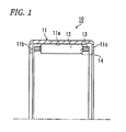
FIG. 1 is a cross-sectional view of a drawn cup needle bearing according to a first embodiment of the present invention; -
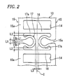
FIG. 2 is a partially enlarged plane view of a cage illustrated inFIG 1 ; -
FIG 3 is an enlarged plane view of a main part ofFIG 2 ; -
FIG. 4 is an explanatory diagram illustrating radial deformation of an elastic deformation portion illustrated inFIG. 2 ; -
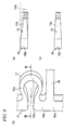
FIG 5(a) illustrates the cage before elastic deformation and a cross-sectional view of a drawn cup, andFIG. 5(b) is a side view seen in a direction V ofFIG. 5(a) ; -
FIG. 6(a) illustrates the cage after elastic deformation and a cross-sectional view of the drawn cup, andFIG. 6(b) is a side view seen in a direction VI ofFIG. 6(a) ; -
FIG. 7 is an enlarged view of a main part of the cage after elastic deformation; -
FIG. 8 is a partially enlarged plane view of a cage of a drawn cup needle bearing according to a second embodiment of the present invention; -
FIG. 9(a) is an explanatory diagram illustrating radial deformation in a variation of an elastic deformation portion,FIG. 9(b) is a cross-sectional view taken along the line IX-IX ofFIG. 9(a), and FIG. 9(c) is a cross-sectional view according to another variation of the elastic deformation portion and corresponding toFIG. 9(b) ; -
FIG. 10 is a cross-sectional view illustrating a conventional drawn cup needle bearing; and -
FIG. 11 is a perspective view illustrating a cage of another conventional needle bearing. - Hereinafter, a needle bearing according to each embodiment of the present invention will be described in detail with reference to the drawings.
- A drawn cup needle bearing 10 according to a first embodiment is placed, for example, between gear trains in an AT, between a gear shaft and a housing or at a lateral position with respect to an oil pump gear, and is reduced in thickness at a bearing cross-sectional height of about 1.0 mm to about 3.5 mm. As illustrated in
FIG. 1 , this drawn cup needle bearing 10 includes: a drawn cup (collared outer ring) 11 serving as a bearing ring having, at its inner peripheral surface, araceway surface 11a and having, at its end portions, a pair ofinward flanges needles 12 placed inside the drawncup 11 so as to be rolled along theraceway surface 11a of the drawncup 11; and acage 13 having a plurality ofpockets 14 for holding the plurality ofneedles 12, threby rotatably supporting an unillustrated shaft (or an inner ring member). - The drawn
cup 11 is formed into a cylindrical shape as a whole by performing plastic working such as drawing on a material such as a special alloy steel sheet, and the pair offlanges cup 11 is hardened by a heat treatment by a carburization or carbonitriding process. - Further, as illustrated in
FIG. 2 , thecage 13 includes: a pair ofrims columns 16 through which the pair ofrims rims shaped portions 15a, and a plurality ofcuts 15c are formed in therims end portions shaped portions 15a circumferentially adjacent to each other. Note that the number of theneedles 12 is reduced when the number of thecuts 15c is increased, and therefore, the number of thecuts 15c is preferably two to six. - Furthermore, at positions between the circumferentially
adjacent columns cuts 15c are formed, thecage 13 is circumferentially provided with a plurality ofelastic deformation portions 17 that are allowed to be circumferentially shrunk. - With the
end portions shaped portions elastic deformation portions 17 are each extended axially inward from therespective end portions 15b, and each have a pair ofelastic deformation pieces elastic deformation pieces elastic deformation portion 17 is formed symmetrically with respect to an axial intermediate portion C. - As illustrated in
FIG. 3 in an enlarged manner, eachelastic deformation piece 17a is formed by a plurality of arcs 17a1, 17a2 and 17a3 having radii of curvature R1 to R3, respectively. It is to be noted that eachelastic deformation piece 17a may be formed by a single arc. - Further, in consideration of strength of the base end, an axial width wl of each
end portion 15b of the arc-shaped portion 15a, serving as the base end of theelastic deformation piece 17a, is preferably equal to or greater than an axial width w2 of the arc-shaped portion 15a. Furthermore, a curvature of an arc surface formed at an axially inner surface of the base end is preferably large (i.e., preferably has a small radius of curvature r). - Moreover, as illustrated in
FIG. 4 , a radial thickness h of theelastic deformation piece 17a is set to be larger than a width w3 of theelastic deformation piece 17a, thus making it possible to suppress radial deformation indicated by the arrows. - As illustrated in
FIG. 5 , in thecage 13 having an outer diameter D1, theelastic deformation portion 17 is deformed, thereby narrowing a circumferential distance L1 of thecut 15c and shrinking thecage 13 in a circumferential direction. As a result, as illustrated inFIG. 6 , thecage 13 is reduced in diameter to an outer diameter D1' smaller than an inner diameter D2 of the drawncup 11, and is thus inserted into the drawncup 11. Accordingly, a relationship among an outer peripheral length of thecage 15, a total sum of the circumferential distances L1 of thecuts 15c, and an inner peripheral length of theinward flanges cup 11 is represented by the following expression:
- Note that a movable range, i.e., a deformation amount of each elastic deformation piece, is freely settable in accordance with an axial distance L3 between the pair of
elastic deformation pieces cut 15c. However, so as to prevent thecolumns 16 and theelastic deformation pieces 17a from coming into contact with each other before thecuts 15c disappear, the circumferential distance L1 of thecut 15c prior to elastic deformation is set to be smaller than a total sum of circumferential distances L2, L2 between theadjacent columns 16 andelastic deformation pieces 17a. Hence, althoughFIG. 6 illustrates a state in which thecolumns 16 and theelastic deformation pieces 17a come into contact with each other and theelastic deformation pieces 17a come into contact with each other upon disappearance of thecuts 15c, thecolumns 16 and theelastic deformation pieces 17a might not come into contact with each other and theelastic deformation pieces 17a might not come into contact with each other upon disappearance of thecuts 15c as illustrated inFIG. 7 . - Accordingly, in the drawn
cup needle bearing 10 of the present embodiment, thecage 13 is circumferentially provided with the plurality ofelastic deformation portions 17 that are allowed to be circumferentially shrunk, and theelastic deformation portions 17 are formed symmetrically with respect to the axial intermediate portion C, thus making it possible to provide thecage 13 capable of being circumferentially shrunk while preventing plastic deformation, obtaining a sufficient strength for axial torsion, and ensuring a sufficient deformation amount. Besides, theelastic deformation portions 17 allow movements of theneedles 12 and can thus also prevent fretting. - In addition, the pair of
rims portions cuts 15c are formed in the pair ofrims portions 15a; furthermore, theelastic deformation portions 17 are each extended axially inward from therespective end portions 15b of the adjacent arc-shapedportions 15a, and each have the pair ofelastic deformation pieces elastic deformation portions 17 symmetrical with respect to the axial intermediate portion C can be formed. - Moreover, each
elastic deformation portion 17 is formed between the circumferentiallyadjacent columns cut 15c is smaller than a total sum of the circumferential distances L2 between theadjacent columns 16 andelastic deformation pieces 17a; hence, when circumferential shrinkage is caused, thecolumns 16 and theelastic deformation pieces 17a will not come into contact with each other before thecuts 15c disappear, thus making it possible to ensure a sufficient deformation amount. -
FIG. 5 illustrates a cage 13' of a drawn cup needle bearing according to a second embodiment of the present invention. This cage 13' is also circumferentially provided with a plurality of (four in the present embodiment) elastic deformation portions 17', which are allowed to be circumferentially shrunk or extended, at positions between circumferentiallyadjacent columns cuts 15c are formed. - With
end portions portions elastic deformation pieces portions end portions circumferential connection portions portions elastic deformation pieces elastic deformation portions 17 are formed symmetrically with respect to an axial intermediate portion C. - Note that also in the present embodiment, a movable range, i.e., a deformation amount of each elastic deformation piece, is freely settable in accordance with an axial distance L3 between the pair of
elastic deformation pieces cut 15c. However, so as to prevent thecolumns 16 and theelastic deformation pieces 17a from coming into contact with each other before thecuts 15c disappear, the circumferential distance L1 of thecut 15c prior to elastic deformation is set to be smaller than a total sum of circumferential distances L2, L2 between theadjacent columns 16 andelastic deformation pieces 17a. - Accordingly, also in the drawn
cup needle bearing 10 of the present embodiment, the cage 13' is circumferentially provided with the plurality of elastic deformation portions 17' that are allowed to be circumferentially shrunk, and the elastic deformation portions 17' are formed symmetrically with respect to the axial intermediate portion C, thus making it possible to provide the cage 13' capable of being circumferentially shrunk while preventing plastic deformation, obtaining a sufficient strength for axial torsion, and ensuring a sufficient deformation amount. - Note that in the elastic deformation portions 17' of the present embodiment, the
elastic deformation pieces 17a will not come into contact with each other by deformation, but stress concentration is likely to occur because they have shapes with comers; hence, the shapes of theelastic deformation portions 17 according to the first embodiment are more preferable. Besides, the shapes of theelastic deformation portions 17 according to the first embodiment are more preferable also in terms of formability during injection molding since resin fluidity is high. - Note that the present invention is not limited to each of the foregoing embodiments, but suitable modifications, improvements and the like may be made.
- For example, as illustrated in
FIGS. 9(a) and (b) , an outer peripheral surface of theelastic deformation piece 17 of theelastic deformation portion 17 according to the first embodiment may be tapered so as to be gradually radially reduced in thickness from theend portions 15b of the arc-shapedportions 15 to an axial inward end portion of theelastic deformation piece 17a. As a result, even when the axial inward end portion of theelastic deformation piece 17a, which serves as a free end side thereof, is deformed radially outward due to centrifugal force as indicated by imaginary lines ofFIG. 9(b) , the axial inward end portion can be prevented from coming into contact with theraceway surface 11a of the drawncup 11. Note that as illustrated inFIG. 9(c) , in consideration of radially inward deformation of the axial inward end portion of theelastic deformation piece 17a, an inner peripheral surface of theelastic deformation piece 17a may also be tapered so as to be gradually radially reduced in thickness from theend portions 15b of the arc-shapedportions 15 to the axial inward end portion of theelastic deformation piece 17a. Alternatively, only the inner peripheral surface of theelastic deformation piece 17a may be tapered. - In each of the embodiments, the outer ring drawn
cup 11 having, at its inner peripheral surface, theraceway surface 11 a and having, at its end portions, theinward flanges cage 13 is deformed so as to be circumferentially extended and is thus inserted into the drawn cup.
Further, a material for the cage is freely selected as long as it is elastically deformable, but a resin is preferably used; alternatively, a metal may be used, but it is more difficult for a metal to be elastically deformed than a resin, and therefore, the number of elastic deformation portions is set to be increased in that case.
Examples of resins to be used for the cage include: polyamide (nylon resin) such as aromatic polyamide (aromatic PA), polyamide 46, polyamide 6 and polyamide 66; polyphenylene sulfide (PPS); polyether ether ketone (PEEK); polyacetal (POM); and a fluorine resin such as polytetrafluoroethylene (PTFE). Alternatively, a mixture in which the foregoing resin(s) are/is mixed with reinforcing agent(s) such as glass fiber and/or carbon fiber may also be suitably used.
A mixture in which a polyamide resin is mixed with glass fiber or carbon fiber at 5% to 30% to provide a bending elastic modulus of 2000 MPa to 5000 MPa is more preferably used. When the bending elastic modulus falls within this range, deformation portions are allowed to have deformability and necessary rigidity in a more suitable manner. - In addition, the needle bearing according to the present invention achieves enhanced effects when the structure of the needle bearing is thin, but the present invention is also applicable to a needle bearing having any cross-sectional height.
Moreover, although the drawn cup needle bearing obtained by bending and forming of a metal sheet has been described in each of the foregoing embodiments, the present invention is also applicable to a solid type needle bearing obtained by performing shaving on a metal material.
Besides, thecage 15 having theelastic deformation portions 17 or 17' according to the present embodiment is also applicable to a needle bearing having no bearing ring, such as a cage and roller assembly. - The present application is based on Japanese Patent Application No.
2009-294136 filed on Dec. 25, 2009 -
- 10
- needle bearing
- 11
- drawn cup (bearing ring)
- 11a
- raceway surface
- 11b, 11c
- inward flange (flange)
- 12
- needle
- 13, 13'
- cage
- 15
- rim
- 16
- column
- 17, 17'
- elastic deformation portion
Claims (3)
- A needle bearing comprising:a bearing ring comprising:a raceway surface at an inner peripheral surface thereof or an outer peripheral surface thereof; anda pair of flanges at both ends thereof;a plurality of needles disposed in the bearing ring to be rotatable along the raceway surface; anda cage comprising a plurality of pockets for holding the plurality of needles therein,wherein the cage comprises a plurality of elastic deformation portions along a circumferential direction thereof, the plurality of elastic deformation portions being shrunk or extended in the circumferential direction, andwherein the elastic deformation portions are formed symmetrically with respect to an intermediate portion in an axial direction of the cage.
- The needle bearing according to claim 1,
wherein the cage comprises:a pair of rims formed by a plurality of arc-shaped portions; anda plurality of columns through which the pair of rims are axially connected to each other,wherein the pair of rims are formed with a plurality of cuts in the same phase in the circumferential direction between end portions of the arc-shaped portions adjacent to each other in the circumferential direction, and
wherein each of the elastic deformation portions is extended axially inward from the respective end portions of the arc-shaped portions adjacent to each other, and
each of the elastic deformation portions has a pair of elastic deformation pieces through which the extended portions of the elastic deformation portion are connected to each other. - The needle bearing according to claim 2,
wherein each of the elastic deformation portions is formed between the columns adjacent to each other in the circumferential direction, and
wherein a circumferential distance of the cut is smaller than a total sum of circumferential distances between the adjacent columns and the elastic deformation pieces.
Applications Claiming Priority (2)
| Application Number | Priority Date | Filing Date | Title |
|---|---|---|---|
| JP2009294136 | 2009-12-25 | ||
| PCT/JP2010/073425 WO2011078359A1 (en) | 2009-12-25 | 2010-12-24 | Needle bearing |
Publications (3)
| Publication Number | Publication Date |
|---|---|
| EP2518354A1 true EP2518354A1 (en) | 2012-10-31 |
| EP2518354A4 EP2518354A4 (en) | 2017-12-06 |
| EP2518354B1 EP2518354B1 (en) | 2019-06-19 |
Family
ID=44195883
Family Applications (1)
| Application Number | Title | Priority Date | Filing Date |
|---|---|---|---|
| EP10809222.2A Active EP2518354B1 (en) | 2009-12-25 | 2010-12-24 | Needle bearing |
Country Status (6)
| Country | Link |
|---|---|
| US (1) | US8628251B2 (en) |
| EP (1) | EP2518354B1 (en) |
| JP (1) | JP5776547B2 (en) |
| KR (1) | KR101280161B1 (en) |
| CN (1) | CN102224350B (en) |
| WO (1) | WO2011078359A1 (en) |
Cited By (1)
| Publication number | Priority date | Publication date | Assignee | Title |
|---|---|---|---|---|
| US8944696B2 (en) | 2011-10-17 | 2015-02-03 | Nsk Ltd. | Cage for radial roller bearing |
Families Citing this family (10)
| Publication number | Priority date | Publication date | Assignee | Title |
|---|---|---|---|---|
| DE102010056059A1 (en) * | 2010-12-23 | 2012-06-28 | Schaeffler Technologies Gmbh & Co. Kg | Rolling bearing cage and roller bearings |
| WO2013031249A1 (en) * | 2011-08-29 | 2013-03-07 | 日本精工株式会社 | Thrust bearing |
| JP2016029285A (en) * | 2012-12-06 | 2016-03-03 | 日本精工株式会社 | Cage, and cage-and-roller |
| WO2015029271A1 (en) * | 2013-08-26 | 2015-03-05 | 日本精工株式会社 | Method for manufacturing shell-type needle bearing, and manufacturing jig used in manufacture of same |
| JP6062381B2 (en) * | 2014-02-25 | 2017-01-18 | 本田技研工業株式会社 | Bearing and continuously variable transmission equipped with bearing |
| DE102014224751A1 (en) * | 2014-12-03 | 2016-05-25 | Schaeffler Technologies AG & Co. KG | Journal bearing for universal joints and method for producing a journal bearing |
| CN106122267A (en) * | 2016-06-27 | 2016-11-16 | 芜湖市海联机械设备有限公司 | A kind of linear bearing |
| CN108194503A (en) * | 2016-12-08 | 2018-06-22 | 镇江东正精工机械有限公司 | Novel conical needle bearing |
| US11732750B2 (en) | 2021-03-04 | 2023-08-22 | General Electric Company | Bearing system with independent adaptive stifness support |
| WO2024081207A1 (en) * | 2022-10-11 | 2024-04-18 | Koyo Bearings North America Llc | Radial bearing assembly having spring rim retainer |
Family Cites Families (15)
| Publication number | Priority date | Publication date | Assignee | Title |
|---|---|---|---|---|
| NL176969C (en) * | 1974-02-06 | 1985-07-01 | Skf Ind Trading & Dev | BEARING CAGE. |
| IT1159910B (en) * | 1977-10-18 | 1987-03-04 | Skf Kugellagerfabriken Gmbh | CAGE FOR ROLLING BEARING |
| DE9006526U1 (en) * | 1990-06-09 | 1990-08-16 | SKF GmbH, 8720 Schweinfurt | Rolling bearing cage |
| DE4131284A1 (en) * | 1991-09-20 | 1993-03-25 | Schaeffler Waelzlager Kg | Roller cage for needle bearings - includes axial slot(s) with elastic stays joined in one piece with cage ends of rigid plastic material |
| DE4142801A1 (en) * | 1991-12-23 | 1993-06-24 | Skf Gmbh | Needle bearing cage for machine assembly - has linking ends of cage with self locating claws with automatic alignment |
| DE4222185A1 (en) * | 1992-07-06 | 1994-01-13 | Schaeffler Waelzlager Kg | Elastic plastics roller bearing cage - is used esp. for cylindrical and pin bearings in freewheel units and has slot in contg. steel plate spring attached to holder |
| DE4337948A1 (en) * | 1993-11-06 | 1995-05-11 | Schaeffler Waelzlager Kg | Roller bearing cage made of flexible plastic |
| US5848846A (en) * | 1996-07-26 | 1998-12-15 | Ntn Corporation | Shell type needle roller bearing and method of producing the same |
| JP2002005176A (en) * | 2000-06-23 | 2002-01-09 | Nakanishi Metal Works Co Ltd | Synthetic resin cage for roller bearing and method of manufacturing the same |
| JP2002147463A (en) * | 2000-11-13 | 2002-05-22 | Nsk Ltd | Crown type cage |
| JP4211397B2 (en) * | 2003-01-06 | 2009-01-21 | 株式会社ジェイテクト | Roller bearing |
| KR100860544B1 (en) * | 2005-03-14 | 2008-09-26 | 윤석태 | Magnetic fastening device for split roller bearing cage |
| JP2007107614A (en) * | 2005-10-13 | 2007-04-26 | Nsk Ltd | Roller bearing cage |
| JP2008008333A (en) * | 2006-06-27 | 2008-01-17 | Nsk Ltd | Manufacturing method of cage for radial roller bearing |
| JP2008008833A (en) | 2006-06-30 | 2008-01-17 | Sunx Ltd | Multi-optical axis photoelectric sensor |
-
2010
- 2010-12-24 CN CN201080002386.XA patent/CN102224350B/en active Active
- 2010-12-24 JP JP2011505274A patent/JP5776547B2/en active Active
- 2010-12-24 WO PCT/JP2010/073425 patent/WO2011078359A1/en not_active Ceased
- 2010-12-24 EP EP10809222.2A patent/EP2518354B1/en active Active
- 2010-12-24 US US13/060,290 patent/US8628251B2/en active Active
- 2010-12-24 KR KR1020117003797A patent/KR101280161B1/en active Active
Non-Patent Citations (1)
| Title |
|---|
| See references of WO2011078359A1 * |
Cited By (1)
| Publication number | Priority date | Publication date | Assignee | Title |
|---|---|---|---|---|
| US8944696B2 (en) | 2011-10-17 | 2015-02-03 | Nsk Ltd. | Cage for radial roller bearing |
Also Published As
| Publication number | Publication date |
|---|---|
| US8628251B2 (en) | 2014-01-14 |
| KR101280161B1 (en) | 2013-06-28 |
| CN102224350A (en) | 2011-10-19 |
| US20110249928A1 (en) | 2011-10-13 |
| EP2518354B1 (en) | 2019-06-19 |
| CN102224350B (en) | 2014-01-22 |
| EP2518354A4 (en) | 2017-12-06 |
| KR20110091499A (en) | 2011-08-11 |
| JP5776547B2 (en) | 2015-09-09 |
| WO2011078359A1 (en) | 2011-06-30 |
| JPWO2011078359A1 (en) | 2013-05-09 |
Similar Documents
| Publication | Publication Date | Title |
|---|---|---|
| EP2518354B1 (en) | Needle bearing | |
| US9500229B2 (en) | Cage for a toroidal roller bearing | |
| EP1249623B1 (en) | Tapered roller bearing | |
| WO2013160319A1 (en) | Converter collar bearing for a torque converter | |
| US20080232733A1 (en) | Drawn cup roller bearing and method of producing drawn cup roller bearing | |
| JP6041055B2 (en) | Manufacturing method of shell-type needle bearing and manufacturing jig used for manufacturing the same | |
| EP2963306B1 (en) | Preliminary holder for radial needle bearing | |
| DE102013215892A1 (en) | Bearing with a double row polygon bearing | |
| EP2988008A1 (en) | Tapered roller bearing | |
| DE102013215893A1 (en) | Sleeve for a single-row polygon bearing | |
| EP4112956A1 (en) | Cylindrical roller bearing with outer ring | |
| WO2014088060A1 (en) | Method for producing shell-type needle bearing | |
| JP2022138991A (en) | Method of assembling outer ring separation type angular ball bearing | |
| JP2024153197A (en) | Drawn cup needle roller bearing | |
| JP2007333024A (en) | Deep groove ball bearing for transmission | |
| EP2327566A1 (en) | A flanged inner ring for a wheel hub | |
| EP2327567A1 (en) | A flanged inner ring for a wheel hub | |
| EP3096033A1 (en) | Rolling bearing |
Legal Events
| Date | Code | Title | Description |
|---|---|---|---|
| PUAI | Public reference made under article 153(3) epc to a published international application that has entered the european phase |
Free format text: ORIGINAL CODE: 0009012 |
|
| 17P | Request for examination filed |
Effective date: 20110223 |
|
| AK | Designated contracting states |
Kind code of ref document: A1 Designated state(s): AL AT BE BG CH CY CZ DE DK EE ES FI FR GB GR HR HU IE IS IT LI LT LU LV MC MK MT NL NO PL PT RO RS SE SI SK SM TR |
|
| DAX | Request for extension of the european patent (deleted) | ||
| R17P | Request for examination filed (corrected) |
Effective date: 20110223 |
|
| RA4 | Supplementary search report drawn up and despatched (corrected) |
Effective date: 20171107 |
|
| RIC1 | Information provided on ipc code assigned before grant |
Ipc: F16C 33/34 20060101ALI20171101BHEP Ipc: F16C 33/56 20060101ALI20171101BHEP Ipc: F16C 19/46 20060101ALI20171101BHEP Ipc: F16C 19/26 20060101ALI20171101BHEP Ipc: F16C 33/46 20060101AFI20171101BHEP |
|
| GRAP | Despatch of communication of intention to grant a patent |
Free format text: ORIGINAL CODE: EPIDOSNIGR1 |
|
| STAA | Information on the status of an ep patent application or granted ep patent |
Free format text: STATUS: GRANT OF PATENT IS INTENDED |
|
| INTG | Intention to grant announced |
Effective date: 20190205 |
|
| GRAS | Grant fee paid |
Free format text: ORIGINAL CODE: EPIDOSNIGR3 |
|
| GRAA | (expected) grant |
Free format text: ORIGINAL CODE: 0009210 |
|
| STAA | Information on the status of an ep patent application or granted ep patent |
Free format text: STATUS: THE PATENT HAS BEEN GRANTED |
|
| AK | Designated contracting states |
Kind code of ref document: B1 Designated state(s): AL AT BE BG CH CY CZ DE DK EE ES FI FR GB GR HR HU IE IS IT LI LT LU LV MC MK MT NL NO PL PT RO RS SE SI SK SM TR |
|
| REG | Reference to a national code |
Ref country code: GB Ref legal event code: FG4D |
|
| REG | Reference to a national code |
Ref country code: CH Ref legal event code: EP |
|
| REG | Reference to a national code |
Ref country code: IE Ref legal event code: FG4D |
|
| REG | Reference to a national code |
Ref country code: DE Ref legal event code: R096 Ref document number: 602010059576 Country of ref document: DE |
|
| REG | Reference to a national code |
Ref country code: AT Ref legal event code: REF Ref document number: 1145897 Country of ref document: AT Kind code of ref document: T Effective date: 20190715 |
|
| REG | Reference to a national code |
Ref country code: NL Ref legal event code: MP Effective date: 20190619 |
|
| PG25 | Lapsed in a contracting state [announced via postgrant information from national office to epo] |
Ref country code: NO Free format text: LAPSE BECAUSE OF FAILURE TO SUBMIT A TRANSLATION OF THE DESCRIPTION OR TO PAY THE FEE WITHIN THE PRESCRIBED TIME-LIMIT Effective date: 20190919 Ref country code: FI Free format text: LAPSE BECAUSE OF FAILURE TO SUBMIT A TRANSLATION OF THE DESCRIPTION OR TO PAY THE FEE WITHIN THE PRESCRIBED TIME-LIMIT Effective date: 20190619 Ref country code: LT Free format text: LAPSE BECAUSE OF FAILURE TO SUBMIT A TRANSLATION OF THE DESCRIPTION OR TO PAY THE FEE WITHIN THE PRESCRIBED TIME-LIMIT Effective date: 20190619 Ref country code: HR Free format text: LAPSE BECAUSE OF FAILURE TO SUBMIT A TRANSLATION OF THE DESCRIPTION OR TO PAY THE FEE WITHIN THE PRESCRIBED TIME-LIMIT Effective date: 20190619 Ref country code: SE Free format text: LAPSE BECAUSE OF FAILURE TO SUBMIT A TRANSLATION OF THE DESCRIPTION OR TO PAY THE FEE WITHIN THE PRESCRIBED TIME-LIMIT Effective date: 20190619 Ref country code: AL Free format text: LAPSE BECAUSE OF FAILURE TO SUBMIT A TRANSLATION OF THE DESCRIPTION OR TO PAY THE FEE WITHIN THE PRESCRIBED TIME-LIMIT Effective date: 20190619 |
|
| REG | Reference to a national code |
Ref country code: LT Ref legal event code: MG4D |
|
| PG25 | Lapsed in a contracting state [announced via postgrant information from national office to epo] |
Ref country code: BG Free format text: LAPSE BECAUSE OF FAILURE TO SUBMIT A TRANSLATION OF THE DESCRIPTION OR TO PAY THE FEE WITHIN THE PRESCRIBED TIME-LIMIT Effective date: 20190919 Ref country code: GR Free format text: LAPSE BECAUSE OF FAILURE TO SUBMIT A TRANSLATION OF THE DESCRIPTION OR TO PAY THE FEE WITHIN THE PRESCRIBED TIME-LIMIT Effective date: 20190920 Ref country code: RS Free format text: LAPSE BECAUSE OF FAILURE TO SUBMIT A TRANSLATION OF THE DESCRIPTION OR TO PAY THE FEE WITHIN THE PRESCRIBED TIME-LIMIT Effective date: 20190619 Ref country code: LV Free format text: LAPSE BECAUSE OF FAILURE TO SUBMIT A TRANSLATION OF THE DESCRIPTION OR TO PAY THE FEE WITHIN THE PRESCRIBED TIME-LIMIT Effective date: 20190619 |
|
| REG | Reference to a national code |
Ref country code: AT Ref legal event code: MK05 Ref document number: 1145897 Country of ref document: AT Kind code of ref document: T Effective date: 20190619 |
|
| PG25 | Lapsed in a contracting state [announced via postgrant information from national office to epo] |
Ref country code: SK Free format text: LAPSE BECAUSE OF FAILURE TO SUBMIT A TRANSLATION OF THE DESCRIPTION OR TO PAY THE FEE WITHIN THE PRESCRIBED TIME-LIMIT Effective date: 20190619 Ref country code: RO Free format text: LAPSE BECAUSE OF FAILURE TO SUBMIT A TRANSLATION OF THE DESCRIPTION OR TO PAY THE FEE WITHIN THE PRESCRIBED TIME-LIMIT Effective date: 20190619 Ref country code: EE Free format text: LAPSE BECAUSE OF FAILURE TO SUBMIT A TRANSLATION OF THE DESCRIPTION OR TO PAY THE FEE WITHIN THE PRESCRIBED TIME-LIMIT Effective date: 20190619 Ref country code: PT Free format text: LAPSE BECAUSE OF FAILURE TO SUBMIT A TRANSLATION OF THE DESCRIPTION OR TO PAY THE FEE WITHIN THE PRESCRIBED TIME-LIMIT Effective date: 20191021 Ref country code: AT Free format text: LAPSE BECAUSE OF FAILURE TO SUBMIT A TRANSLATION OF THE DESCRIPTION OR TO PAY THE FEE WITHIN THE PRESCRIBED TIME-LIMIT Effective date: 20190619 Ref country code: CZ Free format text: LAPSE BECAUSE OF FAILURE TO SUBMIT A TRANSLATION OF THE DESCRIPTION OR TO PAY THE FEE WITHIN THE PRESCRIBED TIME-LIMIT Effective date: 20190619 Ref country code: NL Free format text: LAPSE BECAUSE OF FAILURE TO SUBMIT A TRANSLATION OF THE DESCRIPTION OR TO PAY THE FEE WITHIN THE PRESCRIBED TIME-LIMIT Effective date: 20190619 |
|
| PG25 | Lapsed in a contracting state [announced via postgrant information from national office to epo] |
Ref country code: IT Free format text: LAPSE BECAUSE OF FAILURE TO SUBMIT A TRANSLATION OF THE DESCRIPTION OR TO PAY THE FEE WITHIN THE PRESCRIBED TIME-LIMIT Effective date: 20190619 Ref country code: SM Free format text: LAPSE BECAUSE OF FAILURE TO SUBMIT A TRANSLATION OF THE DESCRIPTION OR TO PAY THE FEE WITHIN THE PRESCRIBED TIME-LIMIT Effective date: 20190619 Ref country code: ES Free format text: LAPSE BECAUSE OF FAILURE TO SUBMIT A TRANSLATION OF THE DESCRIPTION OR TO PAY THE FEE WITHIN THE PRESCRIBED TIME-LIMIT Effective date: 20190619 Ref country code: IS Free format text: LAPSE BECAUSE OF FAILURE TO SUBMIT A TRANSLATION OF THE DESCRIPTION OR TO PAY THE FEE WITHIN THE PRESCRIBED TIME-LIMIT Effective date: 20191019 |
|
| PG25 | Lapsed in a contracting state [announced via postgrant information from national office to epo] |
Ref country code: TR Free format text: LAPSE BECAUSE OF FAILURE TO SUBMIT A TRANSLATION OF THE DESCRIPTION OR TO PAY THE FEE WITHIN THE PRESCRIBED TIME-LIMIT Effective date: 20190619 |
|
| PG25 | Lapsed in a contracting state [announced via postgrant information from national office to epo] |
Ref country code: PL Free format text: LAPSE BECAUSE OF FAILURE TO SUBMIT A TRANSLATION OF THE DESCRIPTION OR TO PAY THE FEE WITHIN THE PRESCRIBED TIME-LIMIT Effective date: 20190619 Ref country code: DK Free format text: LAPSE BECAUSE OF FAILURE TO SUBMIT A TRANSLATION OF THE DESCRIPTION OR TO PAY THE FEE WITHIN THE PRESCRIBED TIME-LIMIT Effective date: 20190619 |
|
| PG25 | Lapsed in a contracting state [announced via postgrant information from national office to epo] |
Ref country code: IS Free format text: LAPSE BECAUSE OF FAILURE TO SUBMIT A TRANSLATION OF THE DESCRIPTION OR TO PAY THE FEE WITHIN THE PRESCRIBED TIME-LIMIT Effective date: 20200224 |
|
| REG | Reference to a national code |
Ref country code: DE Ref legal event code: R097 Ref document number: 602010059576 Country of ref document: DE |
|
| PLBE | No opposition filed within time limit |
Free format text: ORIGINAL CODE: 0009261 |
|
| STAA | Information on the status of an ep patent application or granted ep patent |
Free format text: STATUS: NO OPPOSITION FILED WITHIN TIME LIMIT |
|
| PG2D | Information on lapse in contracting state deleted |
Ref country code: IS |
|
| REG | Reference to a national code |
Ref country code: CH Ref legal event code: PL |
|
| 26N | No opposition filed |
Effective date: 20200603 |
|
| REG | Reference to a national code |
Ref country code: BE Ref legal event code: MM Effective date: 20191231 |
|
| PG25 | Lapsed in a contracting state [announced via postgrant information from national office to epo] |
Ref country code: MC Free format text: LAPSE BECAUSE OF FAILURE TO SUBMIT A TRANSLATION OF THE DESCRIPTION OR TO PAY THE FEE WITHIN THE PRESCRIBED TIME-LIMIT Effective date: 20190619 Ref country code: SI Free format text: LAPSE BECAUSE OF FAILURE TO SUBMIT A TRANSLATION OF THE DESCRIPTION OR TO PAY THE FEE WITHIN THE PRESCRIBED TIME-LIMIT Effective date: 20190619 |
|
| GBPC | Gb: european patent ceased through non-payment of renewal fee |
Effective date: 20191224 |
|
| PG25 | Lapsed in a contracting state [announced via postgrant information from national office to epo] |
Ref country code: LU Free format text: LAPSE BECAUSE OF NON-PAYMENT OF DUE FEES Effective date: 20191224 Ref country code: IE Free format text: LAPSE BECAUSE OF NON-PAYMENT OF DUE FEES Effective date: 20191224 Ref country code: FR Free format text: LAPSE BECAUSE OF NON-PAYMENT OF DUE FEES Effective date: 20191231 Ref country code: GB Free format text: LAPSE BECAUSE OF NON-PAYMENT OF DUE FEES Effective date: 20191224 |
|
| PG25 | Lapsed in a contracting state [announced via postgrant information from national office to epo] |
Ref country code: BE Free format text: LAPSE BECAUSE OF NON-PAYMENT OF DUE FEES Effective date: 20191231 Ref country code: LI Free format text: LAPSE BECAUSE OF NON-PAYMENT OF DUE FEES Effective date: 20191231 Ref country code: CH Free format text: LAPSE BECAUSE OF NON-PAYMENT OF DUE FEES Effective date: 20191231 |
|
| PG25 | Lapsed in a contracting state [announced via postgrant information from national office to epo] |
Ref country code: CY Free format text: LAPSE BECAUSE OF FAILURE TO SUBMIT A TRANSLATION OF THE DESCRIPTION OR TO PAY THE FEE WITHIN THE PRESCRIBED TIME-LIMIT Effective date: 20190619 |
|
| PG25 | Lapsed in a contracting state [announced via postgrant information from national office to epo] |
Ref country code: HU Free format text: LAPSE BECAUSE OF FAILURE TO SUBMIT A TRANSLATION OF THE DESCRIPTION OR TO PAY THE FEE WITHIN THE PRESCRIBED TIME-LIMIT; INVALID AB INITIO Effective date: 20101224 Ref country code: MT Free format text: LAPSE BECAUSE OF FAILURE TO SUBMIT A TRANSLATION OF THE DESCRIPTION OR TO PAY THE FEE WITHIN THE PRESCRIBED TIME-LIMIT Effective date: 20190619 |
|
| PG25 | Lapsed in a contracting state [announced via postgrant information from national office to epo] |
Ref country code: MK Free format text: LAPSE BECAUSE OF FAILURE TO SUBMIT A TRANSLATION OF THE DESCRIPTION OR TO PAY THE FEE WITHIN THE PRESCRIBED TIME-LIMIT Effective date: 20190619 |
|
| PGFP | Annual fee paid to national office [announced via postgrant information from national office to epo] |
Ref country code: DE Payment date: 20251028 Year of fee payment: 16 |