EP2518326A2 - Zentrifugalkompressoranordnung mit Leitschaufelreihe - Google Patents
Zentrifugalkompressoranordnung mit Leitschaufelreihe Download PDFInfo
- Publication number
- EP2518326A2 EP2518326A2 EP12165428A EP12165428A EP2518326A2 EP 2518326 A2 EP2518326 A2 EP 2518326A2 EP 12165428 A EP12165428 A EP 12165428A EP 12165428 A EP12165428 A EP 12165428A EP 2518326 A2 EP2518326 A2 EP 2518326A2
- Authority
- EP
- European Patent Office
- Prior art keywords
- blades
- assembly
- flowpath surface
- flowpath
- impeller
- Prior art date
- Legal status (The legal status is an assumption and is not a legal conclusion. Google has not performed a legal analysis and makes no representation as to the accuracy of the status listed.)
- Withdrawn
Links
Images


Classifications
-
- F—MECHANICAL ENGINEERING; LIGHTING; HEATING; WEAPONS; BLASTING
- F04—POSITIVE - DISPLACEMENT MACHINES FOR LIQUIDS; PUMPS FOR LIQUIDS OR ELASTIC FLUIDS
- F04D—NON-POSITIVE-DISPLACEMENT PUMPS
- F04D29/00—Details, component parts, or accessories
- F04D29/26—Rotors specially for elastic fluids
- F04D29/28—Rotors specially for elastic fluids for centrifugal or helico-centrifugal pumps for radial-flow or helico-centrifugal pumps
- F04D29/284—Rotors specially for elastic fluids for centrifugal or helico-centrifugal pumps for radial-flow or helico-centrifugal pumps for compressors
- F04D29/285—Rotors specially for elastic fluids for centrifugal or helico-centrifugal pumps for radial-flow or helico-centrifugal pumps for compressors the compressor wheel comprising a pair of rotatable bladed hub portions axially aligned and clamped together
-
- F—MECHANICAL ENGINEERING; LIGHTING; HEATING; WEAPONS; BLASTING
- F01—MACHINES OR ENGINES IN GENERAL; ENGINE PLANTS IN GENERAL; STEAM ENGINES
- F01D—NON-POSITIVE DISPLACEMENT MACHINES OR ENGINES, e.g. STEAM TURBINES
- F01D5/00—Blades; Blade-carrying members; Heating, heat-insulating, cooling or antivibration means on the blades or the members
- F01D5/12—Blades
- F01D5/14—Form or construction
- F01D5/141—Shape, i.e. outer, aerodynamic form
- F01D5/146—Shape, i.e. outer, aerodynamic form of blades with tandem configuration, split blades or slotted blades
-
- F—MECHANICAL ENGINEERING; LIGHTING; HEATING; WEAPONS; BLASTING
- F02—COMBUSTION ENGINES; HOT-GAS OR COMBUSTION-PRODUCT ENGINE PLANTS
- F02C—GAS-TURBINE PLANTS; AIR INTAKES FOR JET-PROPULSION PLANTS; CONTROLLING FUEL SUPPLY IN AIR-BREATHING JET-PROPULSION PLANTS
- F02C3/00—Gas-turbine plants characterised by the use of combustion products as the working fluid
- F02C3/04—Gas-turbine plants characterised by the use of combustion products as the working fluid having a turbine driving a compressor
- F02C3/08—Gas-turbine plants characterised by the use of combustion products as the working fluid having a turbine driving a compressor the compressor comprising at least one radial stage
-
- F—MECHANICAL ENGINEERING; LIGHTING; HEATING; WEAPONS; BLASTING
- F04—POSITIVE - DISPLACEMENT MACHINES FOR LIQUIDS; PUMPS FOR LIQUIDS OR ELASTIC FLUIDS
- F04D—NON-POSITIVE-DISPLACEMENT PUMPS
- F04D29/00—Details, component parts, or accessories
- F04D29/26—Rotors specially for elastic fluids
- F04D29/28—Rotors specially for elastic fluids for centrifugal or helico-centrifugal pumps for radial-flow or helico-centrifugal pumps
- F04D29/30—Vanes
-
- F—MECHANICAL ENGINEERING; LIGHTING; HEATING; WEAPONS; BLASTING
- F04—POSITIVE - DISPLACEMENT MACHINES FOR LIQUIDS; PUMPS FOR LIQUIDS OR ELASTIC FLUIDS
- F04D—NON-POSITIVE-DISPLACEMENT PUMPS
- F04D29/00—Details, component parts, or accessories
- F04D29/40—Casings; Connections of working fluid
- F04D29/42—Casings; Connections of working fluid for radial or helico-centrifugal pumps
- F04D29/44—Fluid-guiding means, e.g. diffusers
- F04D29/441—Fluid-guiding means, e.g. diffusers especially adapted for elastic fluid pumps
- F04D29/444—Bladed diffusers
-
- F—MECHANICAL ENGINEERING; LIGHTING; HEATING; WEAPONS; BLASTING
- F05—INDEXING SCHEMES RELATING TO ENGINES OR PUMPS IN VARIOUS SUBCLASSES OF CLASSES F01-F04
- F05D—INDEXING SCHEME FOR ASPECTS RELATING TO NON-POSITIVE-DISPLACEMENT MACHINES OR ENGINES, GAS-TURBINES OR JET-PROPULSION PLANTS
- F05D2220/00—Application
- F05D2220/40—Application in turbochargers
Definitions
- This invention relates generally to gas turbine engine turbines and more particularly to gas turbine engine compressors.
- a centrifugal compressor is a known type of compressor used in a gas turbine engine. It includes a rotating impeller, to impart kinetic energy to a gas flowing through it, with a high swirl level (i.e. tangential velocity) at the impeller's exit.
- a stationary diffuser surrounds the impeller and deswirler system follows the diffuser. Collectively, the diffuser and the deswirler system function to convert the high kinetic energy received from the impeller into the more useful form of static pressure, turn the air flow in a meridional plane by 90 degrees or more, from an outward radial direction to a generally axial direction, and reduce the high tangential velocity component to a small value (typically less than 5 degrees).
- a compressor's pressure ratio is a ratio of the pressure at the exit to the pressure at the inlet.
- PR drives engines to higher thermodynamic efficiency, reducing specific fuel consumption (“SFC”).
- SFC specific fuel consumption
- Increased PR is a function of increased tip speed, which in turn is a function of impeller rotational speed and impeller tip radius.
- Current technology high pressure ratio and high efficiency designs are often at or near mechanical limits for maximum allowable tip speeds, thus limiting any further increase in PR that could be achieved by increased speed. Further increase in pressure ratio may be obtained by larger radius centrifugal stages, but larger radius stages have an undesirable negative impact on engine weight and cost goals.
- a compressor assembly for a gas turbine engine includes: a rotatable impeller with forward and aft ends, including: an annular hub defining a generally concave-curved cross-sectional inner flowpath surface at its radially outer periphery, the inner flowpath surface extending between an inlet and an exit; an annular array of airfoil-shaped inducer blades extending radially outward from the inner flowpath surface near the forward end; and an annular array of exducer blades extending outward from the inner flowpath surface, the array of exducer blades axially spaced apart from the array of inducer blades; a non-rotating shroud assembly surrounding the impeller and including a convex-curved outer flowpath surface, wherein the inner and outer flowpath surfaces cooperate to define a primary flowpath past the blades and the stator vanes; and an annular array of airfoil-shaped stator vanes extending radially inward from the outer flowpath
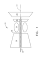
- Figure 1 depicts schematically a gas turbine engine 10 with a central longitudinal axis "A" and including in sequential flow sequence, a compressor 12, a combustor 14, and a gas generator turbine 16.
- the compressor 12 provides compressed air that passes primarily into the combustor 14 to support combustion and partially around the combustor 14 where it is used to cool both the combustor liners and turbomachinery further downstream.
- Fuel is introduced into the forward end of the combustor 14 and is mixed with the air in a conventional fashion.
- the resulting fuel-air mixture flows into the combustor 14 where it is ignited to generate hot combustion gases.
- the hot combustion gases are discharged to the gas generator turbine 16 where they are expanded so that energy is extracted.
- the gas generator turbine 16 drives the compressor 12 through an outer shaft 18.
- the engine 10 is a turboshaft engine and a work turbine (also called a power turbine) 20 is located downstream of the gas generator turbine 16 and coupled to an output shaft 22 which can be connected to a mechanical load.
- a work turbine also called a power turbine
- FIGS 2-4 illustrate a part of the compressor 12, specifically a centrifugal stage 24 which is disposed just upstream from a dome 26 of the annular-type combustor 14. It will be understood that one or more compressor stages (axial, centrifugal, or mixed-flow) of a conventional design may be located upstream of the centrifugal stage 24.
- the centrifugal stage 24 includes an impeller 28 mounted for rotation with the outer shaft 18.
- the impeller 28 includes a hub 30 with axially forward and aft ends 32 and 34 and a central bore 36 passing axially therethrough.
- the hub 30 is constructed from a forward section 40 and an aft section 42 secured together so they rotate as a unit, but they could be part of an integral assembly.
- An outer portion of the hub 30 defines a generally concave-curved inner flowpath surface 44.
- the inner flowpath surface 44 extends in a generally longitudinal direction towards the forward end 32 and extends in a generally radial direction near the aft end 34.
- the impeller 28 includes an inlet 46 and a downstream exit 48.
- An annular array of inducer blades 50 extend radially outward from the inner flowpath surface 44, near the inlet 46.
- Each of the inducer blades 50 is airfoil-shaped (best seen in FIG. 4 ) and has a root 52, a tip 54, and leading and trailing edges 56 and 58, respectively. Opposed pressure and suction sides extend between the leading and trailing edges 56 and 58.
- the inducer blades 50 are configured in terms of their dimensions, cross-sectional shape, orientation, spacing, and other parameters (generally in accordance with conventional practice) to provide an incremental pressure increase to the air flowing past them as the impeller 28 rotates.
- An annular array of exducer blades 60 extend radially outward from the inner flowpath surface 44.
- the exducer blades 60 are axially spaced away from the inducer blades 50 and generally follow the curve of the inner flowpath surface 44 in side elevation view.
- Each of the exducer blades 60 has a root 62, a tip 64, and leading and trailing edges 66 and 68, respectively.
- the exducer blades 60 are configured in terms of their dimensions, cross-sectional shape, orientation, spacing, and other parameters to provide an incremental pressure increase to the air flowing past them as the impeller 28 rotates.
- An annular shroud assembly 70 surrounds the impeller 28.
- the shroud assembly 70 defines a generally convex-curved outer flowpath surface 72 that closely surrounds the tips of the inducer 50 and exducer blades 60. Together the inner and outer flowpath surfaces 44 and 72 define a primary flowpath "F" through the centrifugal stage 24.
- the inner flowpath surface 44 is concave-curved along its entire length.
- the inner flowpath surface 44 may be configured to define a flowpath with a convex-curved convergent-divergent portion through the impeller 28.
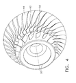
- FIG. 5 shows an impeller 28' with an inlet 46' and exit 48', inducer blades 50', and exducer blades 60' with leading edges 66'.
- the impeller 28' includes an inner flowpath surface 44' which is configured in this alternate manner.
- the inner flowpath surface 44' includes a first portion 74, and a second portion 76 that extends continuously downstream from first portion 74.
- the first portion 74 and second portion 76 are designed independently subject to a common interface, for example, the outlet of first portion 74 is the inlet to second portion 76.
- the first portion 74 is designed according to fan technology knowledge and second portion 76 is designed according to centrifugal compressor technology knowledge.
- the common interface approximately defines a location of the inducer leading edge, such that starting point for an integrally optimized flow path is defined.
- first portion 74 extends upstream from leading edge 56 of the inducer blade 50' towards impeller inlet 46', and second portion 76 extends downstream from trailing edge 58' of the inducer blade 50' towards impeller exit 48'.
- the first portion 74 includes a radially-outwardly-protruding, convex-curved apex 78 near a trailing edge 58' of the inducer blade 50.
- the cross-sectional area of the flowpath F is variable along the longitudinal length of the impeller 28.
- flowpath F has a first cross-sectional area 80 defined between the inner and outer flowpath surfaces 44' and 72 at the inlet 46'.
- the flowpath F has a second cross-sectional area 82 defined between inner and outer flowpath surfaces 44' and 72 at apex 78.
- the flowpath F has a third cross-sectional area 84 defined downstream from apex 78, between the second portion 76 and the outer flowpath surface 72.
- the second cross-sectional area 82 is smaller than first cross-sectional area 80 but equal to or slightly larger than the third area 84.
- the impeller exit 48' has a fourth cross-sectional area 86 defined between the inner and outer flowpath surfaces 44' and 72 at the exit 48'. This cross-sectional area 86 is smaller than cross-sectional areas 80, 82, and 84.
- the impeller work input that produces the required pressure ratio is known to be the product of the wheel linear metal speed and the air, or fluid, turning in the tangential direction.
- the wheel linear metal speed is the radius multiplied by rotational speed. This relationship applies locally as well globally (i.e. on an average basis from inlet to exit). A higher air, or fluid, turning is a result of a higher blade curvature.
- the radius of outer flowpath surface 72 is substantially greater than the radius of inner flowpath surface 44'. This is particularity noted at the near the inlet 46'. Therefore, it is common in prior art practice to balance the work input across the span of the inducer blade 50' at the leading edge by increasing the blade surface curvature (camber) near the inner flowpath surface.
- the inner flowpath surface 44 incorporating the apex 78 essentially increases the average inducer metal speed at the location of the apex 78, so that blade curvature can be reduced, allowing production of efficient and higher-pressure ratio inducer blades 50' than an arrangement with a wholly-concave low hub.
- an annular array of stator vanes 88 extends radially inward from the outer flowpath surface 72.
- the stator vanes 88 project into the axial space between the inducer blades 50 and the exducer blades 60.
- Each of the stator vanes 88 is airfoil-shaped, and has a root 90, a tip 92, and leading and trailing edges 94 and 96, respectively. Opposed pressure and suction sides extend between the leading and trailing edges 94 and 96.
- the stator vanes 88 are configured in terms of their dimensions, cross-sectional shape, orientation, spacing, and other parameters (generally in accordance with conventional practice) to turn the air flowing past them and reduce the swirl (i.e.
- the inner flowpath surface 44 may incorporate a shroud section 98 configured to closely surround the tips 92 of the stator vanes 88 and prevent leakage.
- the shroud section 98 may incorporate an abradable material or other similar structure.
- stator vanes 88 between the inducer blades 50 and exducer blades 60 reduces the flow swirl into the exducer blades 60, thereby increasing the amount of work input required by the exducer blades 60. This allows for a lower tip speed (and therefore lower impeller diameter) than a conventional impeller for the same pressure ratio. Reducing the exducer blades' inlet swirl increases their relative inlet flow angle (i.e. the angle between the longitudinal direction and the inlet flow direction).
- FIGS. 6 and 7 depict a single exducer blade 60 in a schematic form.
- the blade angle ⁇ is defined as the angle between a tangent to the blade's mean-line and the longitudinal direction.
- two radial lines originate at a center and pass through the leading and trailing edges 66 and 68 of the exducer blade 60.
- the angle between the two radial lines is the "wrap angle", denoted "W”.
- the wrap angle W is indicative of the extent of the "footprint" of the exducer blade 60 on the outer flowpath surface 72.
- the exducer blades 60 of the present invention have a significantly increased wrap angle W as compared to prior art designs, for the same overall axial length and outside diameter of the impeller 28.
- stationary diffuser 100 is disposed in flow communication to the impeller exit 48 such that airflow exiting chamber the impeller 28 is channeled through the diffuser 100.
- the diffuser 100 extends radially outward from the impeller 28 and includes an inlet 102 and an outlet 104.
- a deswirler 106 is disposed in flow communication with the diffuser 100 and extends from diffuser outlet 104.
- the deswirler 106 comprises annular inner and outer walls 108 and 110 which form inner and outer boundaries of an arcuate flowpath that turns flow exiting the diffuser 100 from a radial direction to a generally axial direction. In the illustrated example, the air is turned through more than 90 degrees and has a radially-inward velocity component.
- the deswirler 106 contains an annular array of deswirler vanes 112 which are angled to remove swirl (i.e. tangential flow component) from the air exiting the diffuser 100.
Landscapes
- Engineering & Computer Science (AREA)
- Mechanical Engineering (AREA)
- General Engineering & Computer Science (AREA)
- Physics & Mathematics (AREA)
- Fluid Mechanics (AREA)
- Chemical & Material Sciences (AREA)
- Combustion & Propulsion (AREA)
- Structures Of Non-Positive Displacement Pumps (AREA)
Applications Claiming Priority (1)
| Application Number | Priority Date | Filing Date | Title |
|---|---|---|---|
| US13/096,295 US20120272663A1 (en) | 2011-04-28 | 2011-04-28 | Centrifugal compressor assembly with stator vane row |
Publications (2)
| Publication Number | Publication Date |
|---|---|
| EP2518326A2 true EP2518326A2 (de) | 2012-10-31 |
| EP2518326A3 EP2518326A3 (de) | 2014-04-23 |
Family
ID=46027703
Family Applications (1)
| Application Number | Title | Priority Date | Filing Date |
|---|---|---|---|
| EP12165428.9A Withdrawn EP2518326A3 (de) | 2011-04-28 | 2012-04-25 | Zentrifugalkompressoranordnung mit Leitschaufelreihe |
Country Status (4)
| Country | Link |
|---|---|
| US (1) | US20120272663A1 (de) |
| EP (1) | EP2518326A3 (de) |
| JP (1) | JP2012233475A (de) |
| CA (1) | CA2775498A1 (de) |
Cited By (3)
| Publication number | Priority date | Publication date | Assignee | Title |
|---|---|---|---|---|
| EP3018358A1 (de) * | 2014-11-06 | 2016-05-11 | General Electric Company | Kreiselverdichtervorrichtung |
| US9377030B2 (en) | 2013-03-29 | 2016-06-28 | Honeywell International Inc. | Auxiliary power units and other turbomachines having ported impeller shroud recirculation systems |
| WO2017194229A1 (de) * | 2016-05-12 | 2017-11-16 | Man Diesel & Turbo Se | Radialverdichter |
Families Citing this family (13)
| Publication number | Priority date | Publication date | Assignee | Title |
|---|---|---|---|---|
| DE102015219556A1 (de) | 2015-10-08 | 2017-04-13 | Rolls-Royce Deutschland Ltd & Co Kg | Diffusor für Radialverdichter, Radialverdichter und Turbomaschine mit Radialverdichter |
| US10544693B2 (en) * | 2016-06-15 | 2020-01-28 | Honeywell International Inc. | Service routing configuration for a gas turbine engine diffuser system |
| WO2018179173A1 (ja) | 2017-03-29 | 2018-10-04 | 三菱重工エンジン&ターボチャージャ株式会社 | インペラ及び遠心圧縮機 |
| FR3065759B1 (fr) * | 2017-04-26 | 2019-11-29 | Safran Aircraft Engines | Rouet centrifuge pour turbomachine |
| US11536456B2 (en) | 2017-10-24 | 2022-12-27 | General Electric Company | Fuel and air injection handling system for a combustor of a rotating detonation engine |
| US11098730B2 (en) * | 2019-04-12 | 2021-08-24 | Rolls-Royce Corporation | Deswirler assembly for a centrifugal compressor |
| CN110425164A (zh) * | 2019-08-02 | 2019-11-08 | 东莞市能博旺动力科技有限公司 | 一种直流无刷专用风机 |
| US11939070B2 (en) | 2020-02-21 | 2024-03-26 | General Electric Company | Engine-mounting links that have an adjustable inclination angle |
| US11970279B2 (en) | 2020-02-21 | 2024-04-30 | General Electric Company | Control system and methods of controlling an engine-mounting link system |
| US11441516B2 (en) | 2020-07-14 | 2022-09-13 | Rolls-Royce North American Technologies Inc. | Centrifugal compressor assembly for a gas turbine engine with deswirler having sealing features |
| US11286952B2 (en) | 2020-07-14 | 2022-03-29 | Rolls-Royce Corporation | Diffusion system configured for use with centrifugal compressor |
| US11578654B2 (en) | 2020-07-29 | 2023-02-14 | Rolls-Royce North American Technologies Inc. | Centrifical compressor assembly for a gas turbine engine |
| US11959401B1 (en) | 2023-03-24 | 2024-04-16 | Honeywell International Inc. | Deswirl system for gas turbine engine |
Family Cites Families (6)
| Publication number | Priority date | Publication date | Assignee | Title |
|---|---|---|---|---|
| US4135851A (en) * | 1977-05-27 | 1979-01-23 | The United States Of America As Represented By The Administrator Of The National Aeronautics And Space Administration | Composite seal for turbomachinery |
| CA1144125A (en) * | 1979-07-02 | 1983-04-05 | Jesse O. Wiggins | Multi-stage centrifugal compressor |
| US5704759A (en) * | 1996-10-21 | 1998-01-06 | Alliedsignal Inc. | Abrasive tip/abradable shroud system and method for gas turbine compressor clearance control |
| US6589013B2 (en) * | 2001-02-23 | 2003-07-08 | Macro-Micro Devices, Inc. | Fluid flow controller |
| US7798777B2 (en) * | 2006-12-15 | 2010-09-21 | General Electric Company | Engine compressor assembly and method of operating the same |
| US8231341B2 (en) * | 2009-03-16 | 2012-07-31 | Pratt & Whitney Canada Corp. | Hybrid compressor |
-
2011
- 2011-04-28 US US13/096,295 patent/US20120272663A1/en not_active Abandoned
-
2012
- 2012-04-24 JP JP2012098289A patent/JP2012233475A/ja active Pending
- 2012-04-25 EP EP12165428.9A patent/EP2518326A3/de not_active Withdrawn
- 2012-04-26 CA CA2775498A patent/CA2775498A1/en not_active Abandoned
Non-Patent Citations (1)
| Title |
|---|
| None |
Cited By (6)
| Publication number | Priority date | Publication date | Assignee | Title |
|---|---|---|---|---|
| US9377030B2 (en) | 2013-03-29 | 2016-06-28 | Honeywell International Inc. | Auxiliary power units and other turbomachines having ported impeller shroud recirculation systems |
| EP3018358A1 (de) * | 2014-11-06 | 2016-05-11 | General Electric Company | Kreiselverdichtervorrichtung |
| CN105673524A (zh) * | 2014-11-06 | 2016-06-15 | 通用电气公司 | 离心压缩机设备 |
| CN105673524B (zh) * | 2014-11-06 | 2019-01-22 | 通用电气公司 | 离心压缩机设备 |
| WO2017194229A1 (de) * | 2016-05-12 | 2017-11-16 | Man Diesel & Turbo Se | Radialverdichter |
| CN109154304A (zh) * | 2016-05-12 | 2019-01-04 | 曼能源解决方案欧洲股份公司 | 径向压缩机 |
Also Published As
| Publication number | Publication date |
|---|---|
| JP2012233475A (ja) | 2012-11-29 |
| EP2518326A3 (de) | 2014-04-23 |
| CA2775498A1 (en) | 2012-10-28 |
| US20120272663A1 (en) | 2012-11-01 |
Similar Documents
| Publication | Publication Date | Title |
|---|---|---|
| EP2518326A2 (de) | Zentrifugalkompressoranordnung mit Leitschaufelreihe | |
| US8807951B2 (en) | Gas turbine engine airfoil | |
| EP2778427B1 (de) | Selbstrückführendes Kompressorentlüftungssystem | |
| CN109538352B (zh) | 外鼓转子组件和燃气涡轮发动机 | |
| US10544734B2 (en) | Three spool gas turbine engine with interdigitated turbine section | |
| CN105736460B (zh) | 结合非轴对称毂流路和分流叶片的轴向压缩机转子 | |
| JP2006342798A (ja) | 一体形二重反転ターボファン | |
| CN109416050B (zh) | 具有分流器叶片的轴流式压缩机 | |
| JP2017082784A (ja) | スプリッタを搭載した圧縮機 | |
| EP2554793B1 (de) | Zwischenturbinenkanäle mit Leitschaufeln von einer Gasturbinentriebwerk | |
| US20190323355A1 (en) | Combustion chamber arrangement and a gas turbine engine comprising a combustion chamber arrangement | |
| CN111911238A (zh) | 燃气涡轮发动机 | |
| CN112983885B (zh) | 用于燃气涡轮发动机的风扇的分流器和转子翼型件的围带 | |
| US11767768B2 (en) | Unison member for variable guide vane | |
| US10968748B2 (en) | Non-axisymmetric end wall contouring with aft mid-passage peak | |
| EP3098383B1 (de) | Verdichterschaufel mit zusammengesetztem anströmkantenprofil | |
| US20230243268A1 (en) | Airfoils for gas turbine engines | |
| US10876411B2 (en) | Non-axisymmetric end wall contouring with forward mid-passage peak | |
| CA3055849A1 (en) | Compressor stator with leading edge fillet | |
| US11326459B2 (en) | Blade for a gas turbine engine | |
| US20200256202A1 (en) | Blade for a gas turbine engine | |
| US20240044253A1 (en) | Fan for a turbine engine | |
| WO2022201932A1 (ja) | タービン、及びガスタービン | |
| US11401835B2 (en) | Turbine center frame |
Legal Events
| Date | Code | Title | Description |
|---|---|---|---|
| PUAI | Public reference made under article 153(3) epc to a published international application that has entered the european phase |
Free format text: ORIGINAL CODE: 0009012 |
|
| AK | Designated contracting states |
Kind code of ref document: A2 Designated state(s): AL AT BE BG CH CY CZ DE DK EE ES FI FR GB GR HR HU IE IS IT LI LT LU LV MC MK MT NL NO PL PT RO RS SE SI SK SM TR |
|
| AX | Request for extension of the european patent |
Extension state: BA ME |
|
| PUAL | Search report despatched |
Free format text: ORIGINAL CODE: 0009013 |
|
| AK | Designated contracting states |
Kind code of ref document: A3 Designated state(s): AL AT BE BG CH CY CZ DE DK EE ES FI FR GB GR HR HU IE IS IT LI LT LU LV MC MK MT NL NO PL PT RO RS SE SI SK SM TR |
|
| AX | Request for extension of the european patent |
Extension state: BA ME |
|
| RIC1 | Information provided on ipc code assigned before grant |
Ipc: F04D 29/44 20060101ALI20140319BHEP Ipc: F04D 29/28 20060101AFI20140319BHEP Ipc: F04D 29/30 20060101ALI20140319BHEP |
|
| STAA | Information on the status of an ep patent application or granted ep patent |
Free format text: STATUS: THE APPLICATION IS DEEMED TO BE WITHDRAWN |
|
| 18D | Application deemed to be withdrawn |
Effective date: 20141024 |