EP2518273A2 - Axial compressor with arrangement for bleeding air from variable stator vane stages - Google Patents
Axial compressor with arrangement for bleeding air from variable stator vane stages Download PDFInfo
- Publication number
- EP2518273A2 EP2518273A2 EP12165786A EP12165786A EP2518273A2 EP 2518273 A2 EP2518273 A2 EP 2518273A2 EP 12165786 A EP12165786 A EP 12165786A EP 12165786 A EP12165786 A EP 12165786A EP 2518273 A2 EP2518273 A2 EP 2518273A2
- Authority
- EP
- European Patent Office
- Prior art keywords
- casing
- axially
- compressor
- rows
- stator
- Prior art date
- Legal status (The legal status is an assumption and is not a legal conclusion. Google has not performed a legal analysis and makes no representation as to the accuracy of the status listed.)
- Withdrawn
Links
- 230000000740 bleeding effect Effects 0.000 title description 3
- 238000000605 extraction Methods 0.000 claims description 16
- 239000011800 void material Substances 0.000 claims description 6
- 230000001419 dependent effect Effects 0.000 claims 1
- 241000711975 Vesicular stomatitis virus Species 0.000 description 19
- 239000007789 gas Substances 0.000 description 14
- 238000010276 construction Methods 0.000 description 3
- 230000001141 propulsive effect Effects 0.000 description 2
- 230000000694 effects Effects 0.000 description 1
- 230000007613 environmental effect Effects 0.000 description 1
- 239000000446 fuel Substances 0.000 description 1
- 230000007246 mechanism Effects 0.000 description 1
- 230000004048 modification Effects 0.000 description 1
- 238000012986 modification Methods 0.000 description 1
- 238000011144 upstream manufacturing Methods 0.000 description 1
Images


Classifications
-
- F—MECHANICAL ENGINEERING; LIGHTING; HEATING; WEAPONS; BLASTING
- F02—COMBUSTION ENGINES; HOT-GAS OR COMBUSTION-PRODUCT ENGINE PLANTS
- F02C—GAS-TURBINE PLANTS; AIR INTAKES FOR JET-PROPULSION PLANTS; CONTROLLING FUEL SUPPLY IN AIR-BREATHING JET-PROPULSION PLANTS
- F02C9/00—Controlling gas-turbine plants; Controlling fuel supply in air- breathing jet-propulsion plants
- F02C9/16—Control of working fluid flow
- F02C9/18—Control of working fluid flow by bleeding, bypassing or acting on variable working fluid interconnections between turbines or compressors or their stages
-
- F—MECHANICAL ENGINEERING; LIGHTING; HEATING; WEAPONS; BLASTING
- F01—MACHINES OR ENGINES IN GENERAL; ENGINE PLANTS IN GENERAL; STEAM ENGINES
- F01D—NON-POSITIVE DISPLACEMENT MACHINES OR ENGINES, e.g. STEAM TURBINES
- F01D17/00—Regulating or controlling by varying flow
- F01D17/10—Final actuators
- F01D17/105—Final actuators by passing part of the fluid
-
- F—MECHANICAL ENGINEERING; LIGHTING; HEATING; WEAPONS; BLASTING
- F02—COMBUSTION ENGINES; HOT-GAS OR COMBUSTION-PRODUCT ENGINE PLANTS
- F02C—GAS-TURBINE PLANTS; AIR INTAKES FOR JET-PROPULSION PLANTS; CONTROLLING FUEL SUPPLY IN AIR-BREATHING JET-PROPULSION PLANTS
- F02C6/00—Plural gas-turbine plants; Combinations of gas-turbine plants with other apparatus; Adaptations of gas-turbine plants for special use
- F02C6/04—Gas-turbine plants providing heated or pressurised working fluid for other apparatus, e.g. without mechanical power output
- F02C6/06—Gas-turbine plants providing heated or pressurised working fluid for other apparatus, e.g. without mechanical power output providing compressed gas
- F02C6/08—Gas-turbine plants providing heated or pressurised working fluid for other apparatus, e.g. without mechanical power output providing compressed gas the gas being bled from the gas-turbine compressor
-
- F—MECHANICAL ENGINEERING; LIGHTING; HEATING; WEAPONS; BLASTING
- F04—POSITIVE - DISPLACEMENT MACHINES FOR LIQUIDS; PUMPS FOR LIQUIDS OR ELASTIC FLUIDS
- F04D—NON-POSITIVE-DISPLACEMENT PUMPS
- F04D27/00—Control, e.g. regulation, of pumps, pumping installations or pumping systems specially adapted for elastic fluids
- F04D27/02—Surge control
- F04D27/0246—Surge control by varying geometry within the pumps, e.g. by adjusting vanes
-
- F—MECHANICAL ENGINEERING; LIGHTING; HEATING; WEAPONS; BLASTING
- F04—POSITIVE - DISPLACEMENT MACHINES FOR LIQUIDS; PUMPS FOR LIQUIDS OR ELASTIC FLUIDS
- F04D—NON-POSITIVE-DISPLACEMENT PUMPS
- F04D29/00—Details, component parts, or accessories
- F04D29/40—Casings; Connections of working fluid
- F04D29/52—Casings; Connections of working fluid for axial pumps
- F04D29/54—Fluid-guiding means, e.g. diffusers
- F04D29/541—Specially adapted for elastic fluid pumps
- F04D29/545—Ducts
-
- F—MECHANICAL ENGINEERING; LIGHTING; HEATING; WEAPONS; BLASTING
- F04—POSITIVE - DISPLACEMENT MACHINES FOR LIQUIDS; PUMPS FOR LIQUIDS OR ELASTIC FLUIDS
- F04D—NON-POSITIVE-DISPLACEMENT PUMPS
- F04D29/00—Details, component parts, or accessories
- F04D29/40—Casings; Connections of working fluid
- F04D29/52—Casings; Connections of working fluid for axial pumps
- F04D29/54—Fluid-guiding means, e.g. diffusers
- F04D29/56—Fluid-guiding means, e.g. diffusers adjustable
- F04D29/563—Fluid-guiding means, e.g. diffusers adjustable specially adapted for elastic fluid pumps
-
- F—MECHANICAL ENGINEERING; LIGHTING; HEATING; WEAPONS; BLASTING
- F04—POSITIVE - DISPLACEMENT MACHINES FOR LIQUIDS; PUMPS FOR LIQUIDS OR ELASTIC FLUIDS
- F04D—NON-POSITIVE-DISPLACEMENT PUMPS
- F04D27/00—Control, e.g. regulation, of pumps, pumping installations or pumping systems specially adapted for elastic fluids
- F04D27/02—Surge control
- F04D27/0207—Surge control by bleeding, bypassing or recycling fluids
- F04D27/023—Details or means for fluid extraction
Definitions
- This invention relates generally to thermodynamics in gas turbine engines and more particularly to apparatus for extracting bleed air in such engines.
- a gas turbine engine includes a turbomachinery core having a high pressure compressor, combustor, and high pressure turbine in serial flow relationship.
- the core is operable in a known manner to generate a primary flow of propulsive gas.
- a typical turbofan engine adds a low pressure turbine driven by the core exhaust gases which in turn drives a fan rotor through a shaft to generate a bypass flow of propulsive gas. In the case of a high bypass engine this provides the majority of the total engine thrust.
- a typical axial flow high pressure compressor in such an engine includes a number of stages. Each stage has a row of rotating airfoils or blades and row of stationary airfoils or vanes.
- the vanes serve to turn the airflow exiting an upstream row of blades before it enters the downstream row of blades. It is known to construct one or more rows of vanes so that their angle of incidence can be changed in operation. These are referred to as variable stator vanes or simply "VSVs".
- VSVs variable stator vanes
- the VSVs enable throttling of flow through the compressor so that it can operate efficiently at different flow rates, without the losses incurred by other mechanisms such as bleed valves. Because of high overall pressure ratios and stage count in many compressors, there will often be many stages of VSVs.
- bleed air high-pressure compressed air from the high pressure compressor.
- This referred to as "bleed air” and may be used for purposes such as engine or aircraft anti-icing, boundary layer control devices, aircraft environmental control systems and the like.
- bleed should occur at the stage that provides the minimum source pressure the user requires.
- sources have been limited to stages aft of the last VSV stage, because of the structural difficulty of extracting air from the VSV stages.
- the only conveniently available bleed source is at an undesirably high pressure.
- a compressor apparatus includes: a compressor spool mounted for rotation about a centerline axis and carrying a plurality of axially-spaced-apart blade rows, each blade row including an annular array of airfoil-shaped compressor blades; a casing surrounding the compressor blades, the casing carrying a liner assembly which defines a boundary of a primary gas flowpath through the compressor; a plurality of axially-spaced-apart stator rows carried by the liner assembly, each stator row including an annular array of airfoil-shaped stator vanes, wherein the stator rows alternate axially with the blade rows, wherein at least some axially adjacent ones of the stator rows are variable stator rows, the stator vanes of which are mounted on trunnions passing through the casing, so as to be pivotable relative to the casing; an actuator arm coupled to each of the trunnions, outside the casing; at least one first bleed slot passing through the liner structure between axially adjacent first
- FIG. 1 depicts a portion of a high pressure compressor 10, which is part of a gas turbine engine as described above.
- the compressor 10 includes an axially-elongated annular spool 12 mounted for rotation about a centerline axis "A".
- the spool 12 may be built up from several smaller components. In accordance it includes one or more drum portions 14 and several annular disks 16 which all rotate together as a unit.
- the spool 12 is depicted in half-section but it will be understood that it is a body of revolution. Several blade rows are carried at the outer periphery of the spool 12.
- Each blade row comprises an annular array of airfoil-shaped compressor blades 18 which extend radially outward from the spool 12.
- An annular liner assembly 20 closely surrounds the compressor blades 18 and defines the radially outer boundary of a primary gas flowpath through the compressor 10.
- the liner assembly 20 is built up from a plurality of smaller components, some of which will be described in more detail below.
- An annular casing 22 surrounds the liner assembly 20 and provides structural support to it.
- Several stator rows are carried by the liner assembly 20.
- Each stator row comprises an annular array of airfoil-shaped stator vanes 24 which extend radially inward from the liner assembly 20. The stator rows alternate with the blade rows in the axial direction.
- Each blade row and the axially downstream stator row constitute a "stage" of the compressor 10.
- the compressor 10 draws in air (from the left side of the figure) and compresses it as it pumps it axially downstream, towards the right side of the figure.
- Each stage contributes an incremental pressure rise to the air, with the highest pressure being at the exit of the last stage.
- stages of the compressor 10 are shown.
- the stages forward and aft of those illustrated are not of consequence to the invention.
- the stages which are shown are labeled sequentially "S1" through “S7". These numbers are used solely for the sake of easy reference and do not necessarily correspond to the actual number of the stages in the complete compressor 10.
- the four stages S 1 through S4 shown on the left side of the figure (towards an inlet end of the compressor 10) incorporate variable stator vanes or simply "VSVs"; the stator vanes 24 of these stages are constructed so that their angle of incidence can be changed in operation (i.e. these stator vanes 24 can be pivoted about the radial axes shown in dashed lines).
- the remaining stages to the right side of the figure do not incorporate VSVs. It is noted that the principles of the present invention are generally applicable to any axial compressor having two or more axially adjacent stages of VSVs, without regard to the total number of stages, or how many stages include VSVs.
- the VSVs enable throttling of flow through the compressor 10 in a known manner, so that it can operate efficiently at both high and low mass flow rates.
- the stator vane 24 of each stage S1 through S4 has a corresponding trunnion (generically referred to as "26" and labeled 26A through 26D, respectively) that extends radially outward through the liner assembly 20 and the casing 22.
- An actuator arm (generically referred to as "28" and labeled 28A through 28D, respectively) is attached to the distal end of each trunnion 26A-26D. All of the actuator arms 28A-28D for an individual stage are coupled together by a ring 30 (generically referred to as "30" and labeled 30A through 30D, respectively). Rotation of the rings 30A-30D about the engine's longitudinal axis A thus causes all of the actuator arms 28 coupled to that specific ring 30A-30D to move in unison, in turn pivoting all of the trunnions 26A-26D with their attached stator vanes 24 in unison.
- a rear bleed slot 32 which may comprise an annular array of individual slots, penetrates the liner assembly 20 aft of the stage S6.
- the rear bleed slot 32 communicates with a rear plenum 36 defined between the liner assembly 20 and the casing 22.
- One or more rear extraction ports 38 in the casing 22 provide a location to extract the air from the rear plenum 36. In use the rear extraction port 38 would be coupled to appropriate pipework or ducting external to the casing 22(not shown).
- a middle bleed slot 40 which may comprise an annular array of individual slots, penetrates the liner assembly 20 aft of the stage S3.
- the middle bleed slot 40 communicates with a middle plenum 42 defined between the liner assembly 20 and the casing 22 and isolated from the rear plenum 36.
- One or more middle extraction ports 44 in the casing 22 provide a location to extract the air from the middle plenum 42. In use this extraction port 44 would be coupled to appropriate pipework or ducting external to the casing 22 (not shown).
- a forward bleed slot 46 which may comprise an annular array of individual slots, penetrates the liner assembly 20 aft of the stage S1.
- the forward bleed slot 46 communicates with a forward plenum 48 defined between the liner assembly 20 and the casing 22 and isolated from the rear and middle plenums 36 and 42.
- One or more forward extraction ports 50 in the casing 22 provide a place to extract the air from the forward plenum 48. In use this extraction port 50 would be coupled to appropriate pipework or ducting external to the casing 22 (not shown).
- FIG. 2 illustrates in more detail the structure used to bleed air between the stages S1 and S2.
- An annular shroud 52 surrounds the compressor blade 18 as described above.
- the shroud 52 may be made up of a plurality of segments arranged in a ring to form a complete 360 degree assembly.
- the shroud segments may include forward and aft rails 54 and 56 to mount them in slots in the adjacent portions of the liner assembly 20.
- the forward bleed slots 46 described above are formed in the shroud 52 and communicate with the forward plenum 48.
- the forward bleed slots 46 are disposed between the forward rail 54 and the generally tapered-cylindrical central portion 58 of the shroud 52.
- a typical construction would have the liner assembly 20 comprised of a ring of segments and the casing 22 formed in two sections bolted together at a split line flange 60.
- a duct 62 may be positioned in the third plenum 48. As an example, it may have a forward wall 64 and an aft wall 66 which define a flowpath between the shroud 52 and the extraction port 50.
- the duct 62 may be made from two or more arcuate segments assembled into a complete annular shape.
- the forward plenum 48 lies axially between two stages having VSVs.
- the operating hardware of the VSVs is positioned differently than in prior art practice.
- the actuator arms 28B of the stage S1 extend axially forward, while the actuator arms 28C of the stage S2 extend axially rearward.
- the term "axially” refers to directions parallel to the longitudinal axis A shown in FIG. 1 .
- the open void V permits the connection of external pipes or ductwork (not shown) to the extraction port 50.
- air can be bled from the stages S1, S3, and S6, providing air flows at three discrete pressures. As much of the bleed air as possible would be extracted at the lowest possible pressure (i.e. the most forward stage possible) in order to minimize the impact on efficiency and specific fuel consumption (“SFC"). In contrast with prior art bleed arrangements, air may be extracted at a desired pressure despite the fact that such pressure is found at the location of the VSV stages.
- FIG. 3 illustrates a portion of a compressor having a spool 112, compressor blades 118, and stator vanes 124.
- An annular casing 122 surrounds the compressor blades 118 and serves both as a mount for the stator vanes 124 and as a shroud for the compressor blades 118. In effect, it comprises a casing and a liner assembly as described above, in one integral unit.
- Some of the stator vanes 124 are variable-angle (or "VSVs") and include trunnions 126A-126D coupled to actuator arms 128A-128D and rings 130A-130D, respectively.
- VSVs variable-angle
- One stage labeled S2' includes a trunnion 126B, an actuator arm 128B, and a ring 130B.
- the stage S3' immediately downstream of the stage S2' includes a trunnion 126C, an actuator arm 128C, and a ring 130C.
- the actuator arm 128B extends axially forward and the actuator arm 128C extends axially rearward, creating a void "V"' shown by dashed lines.
- a bleed slot 146 is formed through the casing 122 and communicates with a plenum 148. Because of the presence of the void V', the plenum 148 can in turn be coupled to appropriate piping or ductwork (not shown).
- FIG. 4 illustrates an alternative configuration for bleeding air from a compressor.
- the figures shows a portion of a high pressure compressor 210, which is part of a gas turbine engine as described above and is similar in overall construction to the compressor 10 and components which are identical to the compressor 10 will be described in abbreviated fashion.
- the compressor 210 includes an annular spool 212 with blade rows of compressor blades 218.
- An annular liner assembly 220 closely surrounds the compressor blades 218 and defines the radially outer boundary of a primary gas flowpath through the compressor 210.
- the liner assembly 220 is built up from a plurality of smaller components, some of which will be described in more detail below.
- An annular casing 222 surrounds the liner assembly 220 and has several stator rows of stator vanes 224.
- stages of the compressor 210 labeled "S1"” through “S6”” are shown. As noted above, these numbers are used solely for the sake of easy reference and do not necessarily correspond to the actual number of the stages in the complete compressor 210.
- the first three stages shown i.e. S1"-S3" incorporate variable stator vanes as described above.
- the vane 224 of each stage S1" through S3" has a corresponding trunnion (labeled 226A through 226C, respectively) that extends radially outward through the liner assembly 220 and the casing 222.
- the actuating hardware for the trunnions 226A-226C is not shown.
- a rear bleed slot 232 which may comprise an annular array of individual slots, penetrates the liner assembly 220 aft of the stage S5".
- the rear bleed slot 232 communicates with a rear plenum 236 defined between the liner assembly 220 and the casing 222.
- One or more rear extraction ports 238 in the casing 222 provide a location to extract the air from the rear plenum 236. In use the rear extraction port 238 would be coupled to appropriate pipework or ducting external to the casing 222(not shown).
- a middle bleed slot 240 which may comprise an annular array of individual slots, penetrates the liner assembly 220 aft of the stage S2".
- the middle bleed slot 240 communicates with a middle plenum 242 defined between the liner assembly 220 and the casing 222 and isolated from the rear plenum 236.
- One or more middle extraction ports 244 in the casing 222 provide a location to extract the air from the middle plenum 242. In use the middle extraction port 244 would be coupled to appropriate pipework or ducting external to the casing 222 (not shown).
- the forward bleed slot 246 communicates with a forward plenum 248 defined between the liner assembly 220 and the casing 222 and isolated from the rear and middle plenums 236 and 242.
- One or more forward extraction ports 250 in the casing 222 provide a place to extract the air from the forward plenum 248. In use this forward extraction port 250 would be coupled to appropriate pipework or ducting external to the casing 222 (not shown).
- FIG. 5 illustrates in more detail the structure used to bleed air from the stage S1".
- An annular shroud 252 surrounds the compressor blades 218 as described above.
- the shroud 252 may be made up of a plurality of segments arranged in a ring to form a complete 360-degree assembly.
- the shroud segments may include forward and aft rails 254 and 256 to mount them in slots in the surrounding portions of the liner assembly 220.
- the forward bleed slots 246 described above are formed in the shroud 252 and communicate with the forward plenum 248. In this particular example the forward bleed slots 246 are disposed between the forward rail 254 and the generally tapered-cylindrical central portion 258 of the shroud 252.
- the bushings 260 which receive the trunnions 226C pass through an annular wall-like boss 262 which is part of the casing 222.
- the boss 262 In order to pass bleed air across the stage S3", the boss 262 is penetrated at several locations around its periphery by apertures 264.
- the apertures 264 with the trunnions extending across them can be seen in FIG. 6 .
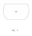
- the trunnions 226C may have an axially-elongated noncircular shape which is smaller is a circumferential direction than an axial direction, as seen in FIG. 7 , in order to increase the lateral space between adjacent trunnions 226 and thereby permit more flow through the apertures 264.
- hollow sleeves 265 may be positioned surrounding the trunnions 226, extending radially across the apertures 264.
- Various means may be used to avoid leakage through the forward plenum 248.
- a typical construction would have the liner assembly 220 comprised of a ring of segments and the casing 222 formed in two sections bolted together at a split line flange 259.
- annular front and rear ducts 266 and 268 may be positioned in the front plenum 248.
- the front duct 266 comprises an arcuate outer wall 270 and an inner wall 272 with an L-shaped cross-section. Together the inner and outer walls 270 and 272 define a flowpath between the shroud 252 and the front face 274 of the boss 262.
- the rear duct 268 comprises an outer wall 276 with a generally U-shaped cross-section and an inner wall 278 with a generally linear cross-section extending aft and radially outward at an angle. Together the inner and outer walls 278 and 276 define a flowpath between the aft face 280 of the boss 262 and the inner surface 282 of the casing 222. Both the front and rear ducts 266 and 268 may be made from two or more arcuate segments assembled into a complete annular shape.
- a particular compressor may have one or multiple bleed locations within either the VSV stages or the non-VSV stages. While locating the bleed port aft of the variable stages maintains compressor length and minimizes VSV complexity, bleeding directly out of the cavity reduces bleed system/leakage losses. In contrast with prior art bleed arrangements, air may be extracted at a desired pressure without regards to the axial location within the compressor. Analysis indicates that the bleed arrangements described here can result in a significant reduction in engine SFC.
Landscapes
- Engineering & Computer Science (AREA)
- Mechanical Engineering (AREA)
- General Engineering & Computer Science (AREA)
- Chemical & Material Sciences (AREA)
- Combustion & Propulsion (AREA)
- Physics & Mathematics (AREA)
- Fluid Mechanics (AREA)
- Geometry (AREA)
- Structures Of Non-Positive Displacement Pumps (AREA)
Abstract
Description
- This invention relates generally to thermodynamics in gas turbine engines and more particularly to apparatus for extracting bleed air in such engines.
- A gas turbine engine includes a turbomachinery core having a high pressure compressor, combustor, and high pressure turbine in serial flow relationship. The core is operable in a known manner to generate a primary flow of propulsive gas. A typical turbofan engine adds a low pressure turbine driven by the core exhaust gases which in turn drives a fan rotor through a shaft to generate a bypass flow of propulsive gas. In the case of a high bypass engine this provides the majority of the total engine thrust.
- A typical axial flow high pressure compressor in such an engine includes a number of stages. Each stage has a row of rotating airfoils or blades and row of stationary airfoils or vanes. The vanes serve to turn the airflow exiting an upstream row of blades before it enters the downstream row of blades. It is known to construct one or more rows of vanes so that their angle of incidence can be changed in operation. These are referred to as variable stator vanes or simply "VSVs". The VSVs enable throttling of flow through the compressor so that it can operate efficiently at different flow rates, without the losses incurred by other mechanisms such as bleed valves. Because of high overall pressure ratios and stage count in many compressors, there will often be many stages of VSVs.
- It is known to extract high-pressure compressed air from the high pressure compressor. This referred to as "bleed air" and may be used for purposes such as engine or aircraft anti-icing, boundary layer control devices, aircraft environmental control systems and the like. For optimal engine performance, bleed should occur at the stage that provides the minimum source pressure the user requires. However, in the prior art, sources have been limited to stages aft of the last VSV stage, because of the structural difficulty of extracting air from the VSV stages. Thus, the only conveniently available bleed source is at an undesirably high pressure.
- Accordingly, there is a need for a compressor which allows air to be bled from the VSV stages.
- This need is addressed by the present invention, which provides a compressor bleed apparatus which bleeds air between VSV stages and provides a path for the air to be extracted clear of structure external to the compressor casing.
- According to one aspect of the invention a compressor apparatus includes: a compressor spool mounted for rotation about a centerline axis and carrying a plurality of axially-spaced-apart blade rows, each blade row including an annular array of airfoil-shaped compressor blades; a casing surrounding the compressor blades, the casing carrying a liner assembly which defines a boundary of a primary gas flowpath through the compressor; a plurality of axially-spaced-apart stator rows carried by the liner assembly, each stator row including an annular array of airfoil-shaped stator vanes, wherein the stator rows alternate axially with the blade rows, wherein at least some axially adjacent ones of the stator rows are variable stator rows, the stator vanes of which are mounted on trunnions passing through the casing, so as to be pivotable relative to the casing; an actuator arm coupled to each of the trunnions, outside the casing; at least one first bleed slot passing through the liner structure between axially adjacent first and second ones of the variable stator rows; and a first flow path defined by the casing, communicating with the at least one first bleed slot and with the exterior of the casing.
- The invention may be best understood by reference to the following description taken in conjunction with the accompanying drawing figures in which:
-
FIG. 1 is a half cross-sectional view of a high pressure compressor of a gas turbine engine, constructed in accordance with an aspect of the present invention; -
FIG. 2 is an enlarged view of a portion ofFIG. 1 ; -
FIG. 3 is a half cross-sectional view of an alternative high pressure compressor of a gas turbine engine, constructed in accordance with an aspect of the present invention; -
FIG. 4 is a half cross-sectional view of another alternative high pressure compressor of a gas turbine engine, constructed in accordance with an aspect of the present invention; -
FIG. 5 is an enlarged view of a portion ofFIG. 4 , showing an optional duct and sleeve; -
FIG. 6 is a perspective view of a portion of the compressor ofFIG. 4 ; and -
FIG. 7 is a cross-sectional view taken along lines 7-7 ofFIG. 5 . - Referring to the drawings wherein identical reference numerals denote the same elements throughout the various views,
FIG. 1 depicts a portion of ahigh pressure compressor 10, which is part of a gas turbine engine as described above. Thecompressor 10 includes an axially-elongatedannular spool 12 mounted for rotation about a centerline axis "A". Thespool 12 may be built up from several smaller components. In accordance it includes one ormore drum portions 14 and severalannular disks 16 which all rotate together as a unit. Thespool 12 is depicted in half-section but it will be understood that it is a body of revolution. Several blade rows are carried at the outer periphery of thespool 12. Each blade row comprises an annular array of airfoil-shaped compressor blades 18 which extend radially outward from thespool 12. Anannular liner assembly 20 closely surrounds thecompressor blades 18 and defines the radially outer boundary of a primary gas flowpath through thecompressor 10. Theliner assembly 20 is built up from a plurality of smaller components, some of which will be described in more detail below. Anannular casing 22 surrounds theliner assembly 20 and provides structural support to it. Several stator rows are carried by theliner assembly 20. Each stator row comprises an annular array of airfoil-shaped stator vanes 24 which extend radially inward from theliner assembly 20. The stator rows alternate with the blade rows in the axial direction. Each blade row and the axially downstream stator row constitute a "stage" of thecompressor 10. In operation, thecompressor 10 draws in air (from the left side of the figure) and compresses it as it pumps it axially downstream, towards the right side of the figure. Each stage contributes an incremental pressure rise to the air, with the highest pressure being at the exit of the last stage. - In the illustrated example, only some of the stages of the
compressor 10 are shown. The stages forward and aft of those illustrated are not of consequence to the invention. The stages which are shown are labeled sequentially "S1" through "S7". These numbers are used solely for the sake of easy reference and do not necessarily correspond to the actual number of the stages in thecomplete compressor 10. The four stages S 1 through S4 shown on the left side of the figure (towards an inlet end of the compressor 10) incorporate variable stator vanes or simply "VSVs"; thestator vanes 24 of these stages are constructed so that their angle of incidence can be changed in operation (i.e. thesestator vanes 24 can be pivoted about the radial axes shown in dashed lines). The remaining stages to the right side of the figure (towards an exit end of the compressor) do not incorporate VSVs. It is noted that the principles of the present invention are generally applicable to any axial compressor having two or more axially adjacent stages of VSVs, without regard to the total number of stages, or how many stages include VSVs. The VSVs enable throttling of flow through thecompressor 10 in a known manner, so that it can operate efficiently at both high and low mass flow rates. Thestator vane 24 of each stage S1 through S4 has a corresponding trunnion (generically referred to as "26" and labeled 26A through 26D, respectively) that extends radially outward through theliner assembly 20 and thecasing 22. An actuator arm (generically referred to as "28" and labeled 28A through 28D, respectively) is attached to the distal end of eachtrunnion 26A-26D. All of theactuator arms 28A-28D for an individual stage are coupled together by a ring 30 (generically referred to as "30" and labeled 30A through 30D, respectively). Rotation of therings 30A-30D about the engine's longitudinal axis A thus causes all of the actuator arms 28 coupled to thatspecific ring 30A-30D to move in unison, in turn pivoting all of thetrunnions 26A-26D with their attachedstator vanes 24 in unison. - In this particular example a
rear bleed slot 32, which may comprise an annular array of individual slots, penetrates theliner assembly 20 aft of the stage S6. The rearbleed slot 32 communicates with arear plenum 36 defined between theliner assembly 20 and thecasing 22. One or morerear extraction ports 38 in thecasing 22 provide a location to extract the air from therear plenum 36. In use therear extraction port 38 would be coupled to appropriate pipework or ducting external to the casing 22(not shown). - A middle
bleed slot 40, which may comprise an annular array of individual slots, penetrates theliner assembly 20 aft of the stage S3. Themiddle bleed slot 40 communicates with amiddle plenum 42 defined between theliner assembly 20 and thecasing 22 and isolated from therear plenum 36. One or moremiddle extraction ports 44 in thecasing 22 provide a location to extract the air from themiddle plenum 42. In use thisextraction port 44 would be coupled to appropriate pipework or ducting external to the casing 22 (not shown). - A
forward bleed slot 46, which may comprise an annular array of individual slots, penetrates theliner assembly 20 aft of the stage S1. Theforward bleed slot 46 communicates with aforward plenum 48 defined between theliner assembly 20 and thecasing 22 and isolated from the rear andmiddle plenums forward extraction ports 50 in thecasing 22 provide a place to extract the air from theforward plenum 48. In use thisextraction port 50 would be coupled to appropriate pipework or ducting external to the casing 22 (not shown). -
FIG. 2 illustrates in more detail the structure used to bleed air between the stages S1 and S2. Anannular shroud 52 surrounds thecompressor blade 18 as described above. Theshroud 52 may be made up of a plurality of segments arranged in a ring to form a complete 360 degree assembly. The shroud segments may include forward andaft rails liner assembly 20. Theforward bleed slots 46 described above are formed in theshroud 52 and communicate with theforward plenum 48. In this particular example theforward bleed slots 46 are disposed between theforward rail 54 and the generally tapered-cylindricalcentral portion 58 of theshroud 52. A typical construction would have theliner assembly 20 comprised of a ring of segments and thecasing 22 formed in two sections bolted together at asplit line flange 60. To avoid leakage at the joints between these components, a duct 62 may be positioned in thethird plenum 48. As an example, it may have aforward wall 64 and anaft wall 66 which define a flowpath between theshroud 52 and theextraction port 50. The duct 62 may be made from two or more arcuate segments assembled into a complete annular shape. - The
forward plenum 48 lies axially between two stages having VSVs. In order to provide adequate space to bleed air from the stage S 1 and extract that air from theforward plenum 48, the operating hardware of the VSVs is positioned differently than in prior art practice. Specifically, theactuator arms 28B of the stage S1 extend axially forward, while theactuator arms 28C of the stage S2 extend axially rearward. As used herein, the term "axially" refers to directions parallel to the longitudinal axis A shown inFIG. 1 . This creates an open void "V" outboard of thecasing 22, denoted by dashed lines inFIG. 2 , not present in prior art configurations. The open void V permits the connection of external pipes or ductwork (not shown) to theextraction port 50. - In operation, air can be bled from the stages S1, S3, and S6, providing air flows at three discrete pressures. As much of the bleed air as possible would be extracted at the lowest possible pressure (i.e. the most forward stage possible) in order to minimize the impact on efficiency and specific fuel consumption ("SFC"). In contrast with prior art bleed arrangements, air may be extracted at a desired pressure despite the fact that such pressure is found at the location of the VSV stages.
- A similar air bleed configuration may be implemented in a
compressor 110 in which the casing and liner are integrated into a single wall. For example,FIG. 3 illustrates a portion of a compressor having aspool 112,compressor blades 118, andstator vanes 124. Anannular casing 122 surrounds thecompressor blades 118 and serves both as a mount for thestator vanes 124 and as a shroud for thecompressor blades 118. In effect, it comprises a casing and a liner assembly as described above, in one integral unit. Some of thestator vanes 124 are variable-angle (or "VSVs") and includetrunnions 126A-126D coupled toactuator arms 128A-128D and rings 130A-130D, respectively. For illustrative purposes thestator vanes 124 of two axially-adjacent stages will be described. One stage labeled S2' includes atrunnion 126B, anactuator arm 128B, and aring 130B. The stage S3' immediately downstream of the stage S2' includes atrunnion 126C, anactuator arm 128C, and aring 130C. Theactuator arm 128B extends axially forward and theactuator arm 128C extends axially rearward, creating a void "V"' shown by dashed lines. Ableed slot 146 is formed through thecasing 122 and communicates with aplenum 148. Because of the presence of the void V', theplenum 148 can in turn be coupled to appropriate piping or ductwork (not shown). -
FIG. 4 illustrates an alternative configuration for bleeding air from a compressor. The figures shows a portion of ahigh pressure compressor 210, which is part of a gas turbine engine as described above and is similar in overall construction to thecompressor 10 and components which are identical to thecompressor 10 will be described in abbreviated fashion. Thecompressor 210 includes anannular spool 212 with blade rows ofcompressor blades 218. Anannular liner assembly 220 closely surrounds thecompressor blades 218 and defines the radially outer boundary of a primary gas flowpath through thecompressor 210. Theliner assembly 220 is built up from a plurality of smaller components, some of which will be described in more detail below. Anannular casing 222 surrounds theliner assembly 220 and has several stator rows ofstator vanes 224. - In the illustrated example, only some of the stages of the
compressor 210, labeled "S1"" through "S6"" are shown. As noted above, these numbers are used solely for the sake of easy reference and do not necessarily correspond to the actual number of the stages in thecomplete compressor 210. The first three stages shown (i.e. S1"-S3") incorporate variable stator vanes as described above. Thevane 224 of each stage S1" through S3" has a corresponding trunnion (labeled 226A through 226C, respectively) that extends radially outward through theliner assembly 220 and thecasing 222. The actuating hardware for the trunnions 226A-226C is not shown. - A
rear bleed slot 232, which may comprise an annular array of individual slots, penetrates theliner assembly 220 aft of the stage S5". Therear bleed slot 232 communicates with arear plenum 236 defined between theliner assembly 220 and thecasing 222. One or morerear extraction ports 238 in thecasing 222 provide a location to extract the air from therear plenum 236. In use therear extraction port 238 would be coupled to appropriate pipework or ducting external to the casing 222(not shown). - A
middle bleed slot 240, which may comprise an annular array of individual slots, penetrates theliner assembly 220 aft of the stage S2". Themiddle bleed slot 240 communicates with amiddle plenum 242 defined between theliner assembly 220 and thecasing 222 and isolated from therear plenum 236. One or moremiddle extraction ports 244 in thecasing 222 provide a location to extract the air from themiddle plenum 242. In use themiddle extraction port 244 would be coupled to appropriate pipework or ducting external to the casing 222 (not shown). - A
forward bleed slot 246, which may comprise an annular array of individual slots, penetrates theliner assembly 220 aft of the stage S1". Theforward bleed slot 246 communicates with aforward plenum 248 defined between theliner assembly 220 and thecasing 222 and isolated from the rear andmiddle plenums forward extraction ports 250 in thecasing 222 provide a place to extract the air from theforward plenum 248. In use thisforward extraction port 250 would be coupled to appropriate pipework or ducting external to the casing 222 (not shown). -
FIG. 5 illustrates in more detail the structure used to bleed air from the stage S1". Anannular shroud 252 surrounds thecompressor blades 218 as described above. Theshroud 252 may be made up of a plurality of segments arranged in a ring to form a complete 360-degree assembly. The shroud segments may include forward andaft rails liner assembly 220. Theforward bleed slots 246 described above are formed in theshroud 252 and communicate with theforward plenum 248. In this particular example theforward bleed slots 246 are disposed between theforward rail 254 and the generally tapered-cylindricalcentral portion 258 of theshroud 252. - The
bushings 260 which receive thetrunnions 226C pass through an annular wall-like boss 262 which is part of thecasing 222. In order to pass bleed air across the stage S3", theboss 262 is penetrated at several locations around its periphery byapertures 264. Theapertures 264 with the trunnions extending across them can be seen inFIG. 6 . Optionally, thetrunnions 226C may have an axially-elongated noncircular shape which is smaller is a circumferential direction than an axial direction, as seen inFIG. 7 , in order to increase the lateral space between adjacent trunnions 226 and thereby permit more flow through theapertures 264. Optionally, to prevent leakage of bleed air between the trunnions 226 and thecasing 222,hollow sleeves 265 may be positioned surrounding the trunnions 226, extending radially across theapertures 264. - Various means may be used to avoid leakage through the
forward plenum 248. As noted above, a typical construction would have theliner assembly 220 comprised of a ring of segments and thecasing 222 formed in two sections bolted together at asplit line flange 259. To avoid leakage at the joints between these components, annular front andrear ducts front plenum 248. Thefront duct 266 comprises an arcuateouter wall 270 and aninner wall 272 with an L-shaped cross-section. Together the inner andouter walls shroud 252 and thefront face 274 of theboss 262. Therear duct 268 comprises anouter wall 276 with a generally U-shaped cross-section and aninner wall 278 with a generally linear cross-section extending aft and radially outward at an angle. Together the inner andouter walls aft face 280 of theboss 262 and theinner surface 282 of thecasing 222. Both the front andrear ducts - The bleed configurations described above can be combined and/or adapted as need for any desired bleed location. A particular compressor may have one or multiple bleed locations within either the VSV stages or the non-VSV stages. While locating the bleed port aft of the variable stages maintains compressor length and minimizes VSV complexity, bleeding directly out of the cavity reduces bleed system/leakage losses. In contrast with prior art bleed arrangements, air may be extracted at a desired pressure without regards to the axial location within the compressor. Analysis indicates that the bleed arrangements described here can result in a significant reduction in engine SFC.
- The foregoing has described a bleed arrangement for a gas turbine engine compressor. While specific embodiments of the present invention have been described, it will be apparent to those skilled in the art that various modifications thereto can be made without departing from the scope of the invention. Accordingly, the foregoing description of the preferred embodiment of the invention and the best mode for practicing the invention are provided for the purpose of illustration only and not for the purpose of limitation.
Claims (11)
- A compressor apparatus (10,110,210), comprising:a compressor spool (12, 112, 212) mounted for rotation about a centerline axis (A) and carrying a plurality of axially-spaced-apart blade rows, each blade row comprising an annular array of airfoil-shaped compressor blades (18, 118, 218);a casing (22, 122, 222) surrounding the compressor blades (18, 118, 218), the casing (22, 122, 222) carrying a liner assembly (20, 220) which defines a boundary of a primary gas flowpath through the compressor;a plurality of axially-spaced-apart stator rows carried by the liner assembly (20, 220), each stator row comprising an annular array of airfoil-shaped stator vanes (24, 124, 224), wherein the stator rows alternate axially with the blade rows, wherein at least some axially adjacent ones of the stator rows are variable stator rows, the stator vanes (24, 124, 224) of which are mounted on trunnions (26, 126, 226) passing through the casing (22, 122, 222), so as to be pivotable relative to the casing (22, 122, 222);an actuator arm (28, 128) coupled to each of the trunnions (26, 126, 226), outside the casing (22, 122, 222);at least one first bleed slot (46, 146, 246) passing through the liner assembly (20, 220) between axially adjacent first and second ones of the variable stator rows; anda first flow path defined by the casing (22, 122, 222), communicating with the at least one first bleed slot (46, 146, 246) and with the exterior of the casing (22, 122, 222).
- The apparatus of claim 1 wherein the actuator arms (28, 128) of the first variable stator row extend axially forward and the actuator arms (28, 128) of the second variable stator row extend axially rearward, so as to create an open void (V) at the exterior of the casing (22, 122, 222), which is in general axial alignment with the at least one first bleed slot (46, 146, 246).
- The apparatus of claim 2 wherein the casing (22, 122, 222) includes at least one first extraction port (50, 250) formed at the exterior surface of the casing (22, 122, 222) in flow communication with the first flow path and positioned within forward and aft boundaries of the open void in the axial direction.
- The apparatus of any of the preceding claims wherein the liner assembly (20, 220) is spaced-apart from the remainder of the casing (22, 122, 222) in a radial direction so as to define an open first plenum (48, 148, 248) therebetween, the first plenum (48, 148, 248) defining the boundaries of the first flow path.
- The apparatus of claim 4 wherein the liner carries an annular shroud (52, 252) surrounding one of the blade rows, and the at least one first bleed slot (46, 146, 246) passes through the shroud (52, 252).
- The apparatus of either of claim 4 or 5 further comprising an annular duct (62) with spaced-apart forward and aft walls (64,66) disposed in the first plenum (48, 148, 248).
- The apparatus of any of the preceding claims further including:at least one additional bleed slot (32, 232) passing through the liner assembly (20, 220) axially downstream of all of the variable stator rows; anda second flow path defined by the casing (22, 122, 222) communicating with the at least one additional bleed slot (32, 232) and with at least one additional extraction port (38, 238) which is disposed at an exterior surface of the casing (22, 122, 222), the second flow path being isolated from the first flow path.
- The apparatus of any of claim 4 or any claim dependent theron wherein:the trunnions (26, 126, 226) are mounted in annular bosses (262) extending in a generally radial direction between the liner assembly (20, 220) and the remainder of the casing (22, 122, 222);the at least one first bleed slot (46, 146, 246) is positioned axially forward of a selected one of the bosses (262);the selected boss (262) has at least one aperture (264) formed therein, such that some of the trunnions (26, 126, 226) extend radially across the at least one aperture (264); andthe first flow path passes through the at least one aperture (264) in the selected boss (262) and extends axially aft of the selected boss (262).
- The apparatus of claim 8 further comprising:a forward duct (266) with spaced-apart inner and outer walls (272,270) disposed between the first bleed slot (46, 146, 246) and a forward face (274) of the selected boss (262); anda rear duct (268) with spaced-apart inner and outer walls (278,276) disposed between an aft face (280) of the selected boss (262) and an interior surface of the casing (22, 122, 222).
- The apparatus of either of claim 8 or 9 wherein at least the trunnions (26, 126, 226) which extend across the at least one aperture (264) have a noncircular cross-sectional shape which is narrower in a circumferential direction than in an axial direction.
- The apparatus of any of claims 8 to 10 wherein a sleeve (265) surrounds each of the trunnions (26, 126, 226) that extends across the at least one aperture (264).
Applications Claiming Priority (1)
| Application Number | Priority Date | Filing Date | Title |
|---|---|---|---|
| US13/094,934 US8734091B2 (en) | 2011-04-27 | 2011-04-27 | Axial compressor with arrangement for bleeding air from variable stator vane stages |
Publications (2)
| Publication Number | Publication Date |
|---|---|
| EP2518273A2 true EP2518273A2 (en) | 2012-10-31 |
| EP2518273A3 EP2518273A3 (en) | 2017-04-19 |
Family
ID=46084830
Family Applications (1)
| Application Number | Title | Priority Date | Filing Date |
|---|---|---|---|
| EP12165786.0A Withdrawn EP2518273A3 (en) | 2011-04-27 | 2012-04-26 | Axial compressor with arrangement for bleeding air from variable stator vane stages |
Country Status (4)
| Country | Link |
|---|---|
| US (1) | US8734091B2 (en) |
| EP (1) | EP2518273A3 (en) |
| JP (1) | JP6105208B2 (en) |
| CA (1) | CA2775423A1 (en) |
Cited By (4)
| Publication number | Priority date | Publication date | Assignee | Title |
|---|---|---|---|---|
| EP2881548A1 (en) * | 2013-12-09 | 2015-06-10 | MTU Aero Engines GmbH | Gas turbine compressor |
| EP2960438A1 (en) * | 2014-06-26 | 2015-12-30 | MTU Aero Engines GmbH | Variable guide vane device for a gas turbine and gas turbine equipped with such a device |
| CN106194846A (en) * | 2016-07-12 | 2016-12-07 | 中国航空工业集团公司沈阳发动机设计研究所 | A kind of double-layered case structure compressor and there is its aero-engine |
| EP3483412A1 (en) * | 2017-11-13 | 2019-05-15 | United Technologies Corporation | Gas turbine engine with mid-compressor bleed |
Families Citing this family (23)
| Publication number | Priority date | Publication date | Assignee | Title |
|---|---|---|---|---|
| US9988915B2 (en) * | 2013-03-13 | 2018-06-05 | United Technologies Corporation | Stator segment |
| JP6185781B2 (en) * | 2013-07-23 | 2017-08-23 | 三菱日立パワーシステムズ株式会社 | Axial flow compressor |
| US9657647B2 (en) | 2013-10-15 | 2017-05-23 | The Boeing Company | Methods and apparatus to adjust bleed ports on an aircraft engine |
| US20160298633A1 (en) * | 2013-12-16 | 2016-10-13 | United Technologies Corporation | Shortened support for compressor variable vane |
| EP2993313B1 (en) * | 2014-09-05 | 2019-10-30 | United Technologies Corporation | Offtakes for gas turbine engine secondary gas flows |
| GB2552426A (en) | 2015-03-31 | 2018-01-24 | Halliburton Energy Services Inc | Actuator controlled variable flow area stator for flow splitting in down-hole tools |
| US10215047B2 (en) | 2015-12-28 | 2019-02-26 | General Electric Company | Actuation system utilizing MEMS technology |
| US10302019B2 (en) | 2016-03-03 | 2019-05-28 | General Electric Company | High pressure compressor augmented bleed with autonomously actuated valve |
| US10731663B2 (en) * | 2016-06-21 | 2020-08-04 | Rolls-Royce North American Technologies Inc. | Axial compressor with radially outer annulus |
| US11073160B2 (en) | 2016-09-08 | 2021-07-27 | The United States Of America As Represented By The Secretary Of The Army | Adaptable articulating axial-flow compressor/turbine rotor blade |
| US10539153B2 (en) | 2017-03-14 | 2020-01-21 | General Electric Company | Clipped heat shield assembly |
| US20180313364A1 (en) * | 2017-04-27 | 2018-11-01 | General Electric Company | Compressor apparatus with bleed slot including turning vanes |
| US10934943B2 (en) * | 2017-04-27 | 2021-03-02 | General Electric Company | Compressor apparatus with bleed slot and supplemental flange |
| US10794272B2 (en) * | 2018-02-19 | 2020-10-06 | General Electric Company | Axial and centrifugal compressor |
| DE102018113997A1 (en) * | 2018-06-12 | 2019-12-12 | Rolls-Royce Deutschland Ltd & Co Kg | Housing arrangement for an axial compressor of a gas turbine engine |
| JP7720681B2 (en) * | 2019-08-29 | 2025-08-08 | 三菱重工業株式会社 | Compressors, gas turbines |
| US11866182B2 (en) | 2020-05-01 | 2024-01-09 | General Electric Company | Fuel delivery system having a fuel oxygen reduction unit |
| US11512611B2 (en) * | 2021-02-09 | 2022-11-29 | General Electric Company | Stator apparatus for a gas turbine engine |
| US11781504B2 (en) * | 2021-10-19 | 2023-10-10 | Honeywell International Inc. | Bleed plenum for compressor section |
| CN115234518B (en) * | 2022-08-05 | 2025-05-30 | 中国航发贵阳发动机设计研究所 | A composite function compressor casing with air collecting cavity structure |
| US12110810B2 (en) * | 2022-11-16 | 2024-10-08 | General Electric Company | Gas turbine engine bleed air flow control |
| US12196141B2 (en) | 2023-04-19 | 2025-01-14 | Honeywell International Inc. | Systems and methods with distributed bleed for gas turbine engine compressor stabilization |
| US12247580B2 (en) * | 2023-05-03 | 2025-03-11 | General Electric Company | Forward load reduction structures for aft-most stages of high pressure compressors |
Family Cites Families (19)
| Publication number | Priority date | Publication date | Assignee | Title |
|---|---|---|---|---|
| US3996964A (en) * | 1972-09-15 | 1976-12-14 | The Bendix Corporation | Control apparatus particularly for a plurality of compressor bleed valves of a gas turbine engine |
| US3945759A (en) | 1974-10-29 | 1976-03-23 | General Electric Company | Bleed air manifold |
| DE2740904A1 (en) * | 1977-09-10 | 1979-03-22 | Motoren Turbinen Union | DEVICE FOR OPERATING SHUT-OFF ELEMENTS IN GAS TURBINE ENGINES, IN PARTICULAR GAS TURBINE JET |
| US4791783A (en) * | 1981-11-27 | 1988-12-20 | General Electric Company | Convertible aircraft engine |
| FR2601074B1 (en) * | 1986-07-03 | 1990-05-25 | Snecma | TURBOMACHINE PROVIDED WITH A DEVICE FOR CONTROLLING THE VENTILATION AIR FLOW TAKEN FOR THE CONTROL OF THE GAMES BETWEEN ROTOR AND STATOR. |
| DE3940248A1 (en) * | 1989-04-17 | 1990-10-18 | Gen Electric | METHOD AND DEVICE FOR REGULATING A GAS TURBINE ENGINE |
| US5155993A (en) | 1990-04-09 | 1992-10-20 | General Electric Company | Apparatus for compressor air extraction |
| US5209633A (en) | 1990-11-19 | 1993-05-11 | General Electric Company | High pressure compressor flowpath bleed valve extraction slot |
| US6109868A (en) | 1998-12-07 | 2000-08-29 | General Electric Company | Reduced-length high flow interstage air extraction |
| US6325595B1 (en) | 2000-03-24 | 2001-12-04 | General Electric Company | High recovery multi-use bleed |
| US6413043B1 (en) * | 2000-11-09 | 2002-07-02 | General Electric Company | Inlet guide vane and shroud support contact |
| US6438941B1 (en) * | 2001-04-26 | 2002-08-27 | General Electric Company | Bifurcated splitter for variable bleed flow |
| US6550254B2 (en) | 2001-08-17 | 2003-04-22 | General Electric Company | Gas turbine engine bleed scoops |
| US6783324B2 (en) * | 2002-08-15 | 2004-08-31 | General Electric Company | Compressor bleed case |
| FR2858027B1 (en) * | 2003-07-21 | 2005-09-23 | Snecma Moteurs | HIGH PRESSURE COMPRESSOR WITH A HYBRID CYCLE AND TURBOMACHINE COMPRISING SUCH A COMPRESSOR |
| US7624581B2 (en) | 2005-12-21 | 2009-12-01 | General Electric Company | Compact booster bleed turbofan |
| FR2916815B1 (en) * | 2007-05-30 | 2017-02-24 | Snecma | AIR REINJECTION COMPRESSOR |
| US8388308B2 (en) * | 2007-10-30 | 2013-03-05 | General Electric Company | Asymmetric flow extraction system |
| EP2058524A1 (en) * | 2007-11-12 | 2009-05-13 | Siemens Aktiengesellschaft | Air bleed compressor with variable guide vanes |
-
2011
- 2011-04-27 US US13/094,934 patent/US8734091B2/en active Active
-
2012
- 2012-04-19 CA CA2775423A patent/CA2775423A1/en not_active Abandoned
- 2012-04-24 JP JP2012098293A patent/JP6105208B2/en not_active Expired - Fee Related
- 2012-04-26 EP EP12165786.0A patent/EP2518273A3/en not_active Withdrawn
Non-Patent Citations (1)
| Title |
|---|
| None |
Cited By (7)
| Publication number | Priority date | Publication date | Assignee | Title |
|---|---|---|---|---|
| EP2881548A1 (en) * | 2013-12-09 | 2015-06-10 | MTU Aero Engines GmbH | Gas turbine compressor |
| US10107194B2 (en) | 2013-12-09 | 2018-10-23 | MTU Aero Engines AG | Gas turbine |
| EP2960438A1 (en) * | 2014-06-26 | 2015-12-30 | MTU Aero Engines GmbH | Variable guide vane device for a gas turbine and gas turbine equipped with such a device |
| US10450877B2 (en) | 2014-06-26 | 2019-10-22 | MTU Aero Engines AG | Guide means for a gas turbine and gas turbine having such a guide means |
| CN106194846A (en) * | 2016-07-12 | 2016-12-07 | 中国航空工业集团公司沈阳发动机设计研究所 | A kind of double-layered case structure compressor and there is its aero-engine |
| EP3483412A1 (en) * | 2017-11-13 | 2019-05-15 | United Technologies Corporation | Gas turbine engine with mid-compressor bleed |
| US10626879B2 (en) | 2017-11-13 | 2020-04-21 | United Technologies Corporation | Gas turbine engine with mid-compressor bleed |
Also Published As
| Publication number | Publication date |
|---|---|
| US20120275912A1 (en) | 2012-11-01 |
| EP2518273A3 (en) | 2017-04-19 |
| JP6105208B2 (en) | 2017-03-29 |
| US8734091B2 (en) | 2014-05-27 |
| JP2012233476A (en) | 2012-11-29 |
| CA2775423A1 (en) | 2012-10-27 |
Similar Documents
| Publication | Publication Date | Title |
|---|---|---|
| US8734091B2 (en) | Axial compressor with arrangement for bleeding air from variable stator vane stages | |
| US20180328187A1 (en) | Turbine engine with an airfoil and insert | |
| CN107013335B (en) | Gas turbine engine and cooling circuit therefor | |
| CN1987066B (en) | Compact booster bleed turbofan | |
| US10030587B2 (en) | Annular airflow actuation system for variable cycle gas turbine engines | |
| US20180363676A1 (en) | Inlet pre-swirl gas turbine engine | |
| US20210231052A1 (en) | Radial variable inlet guide vane for axial or axi-centrifugal compressors | |
| US20070209368A1 (en) | High pressure ratio aft fan | |
| JP6043370B2 (en) | Gas turbine engine sump pressurization system | |
| US10794272B2 (en) | Axial and centrifugal compressor | |
| CN106948968A (en) | Variablepiston fan actuator | |
| EP3187692A1 (en) | Systems and methods for a compressor diffusion slot | |
| US10060286B2 (en) | Geared annular airflow actuation system for variable cycle gas turbine engines | |
| US20250264057A1 (en) | Cooling air delivery system and methods thereof | |
| CN107448239A (en) | Turbine engine airfoil part releases pumping | |
| US10393024B2 (en) | Multi-air stream cooling system | |
| EP3208423A1 (en) | Gas turbine engine trailing edge ejection holes | |
| CN112443364B (en) | Actuating assembly for concentric variable stator vanes | |
| CN108019238A (en) | Airfoil component with cooling circuit | |
| US20230304415A1 (en) | Clearance control system for a gas turbine engine | |
| US11401835B2 (en) | Turbine center frame | |
| CN120426132A (en) | Compressor assembly for a gas turbine engine with multi-stage exhaust gas extraction | |
| US12398671B2 (en) | Compressor assembly for a gas turbine engine having multi-stage bleed extraction | |
| CN119593874A (en) | Turbine engine with exhaust system | |
| CN119593873A (en) | Method of operating a turbine engine having an exhaust system |
Legal Events
| Date | Code | Title | Description |
|---|---|---|---|
| PUAI | Public reference made under article 153(3) epc to a published international application that has entered the european phase |
Free format text: ORIGINAL CODE: 0009012 |
|
| AK | Designated contracting states |
Kind code of ref document: A2 Designated state(s): AL AT BE BG CH CY CZ DE DK EE ES FI FR GB GR HR HU IE IS IT LI LT LU LV MC MK MT NL NO PL PT RO RS SE SI SK SM TR |
|
| AX | Request for extension of the european patent |
Extension state: BA ME |
|
| PUAL | Search report despatched |
Free format text: ORIGINAL CODE: 0009013 |
|
| AK | Designated contracting states |
Kind code of ref document: A3 Designated state(s): AL AT BE BG CH CY CZ DE DK EE ES FI FR GB GR HR HU IE IS IT LI LT LU LV MC MK MT NL NO PL PT RO RS SE SI SK SM TR |
|
| AX | Request for extension of the european patent |
Extension state: BA ME |
|
| RIC1 | Information provided on ipc code assigned before grant |
Ipc: F02C 9/18 20060101ALI20170316BHEP Ipc: F02C 6/08 20060101ALI20170316BHEP Ipc: F01D 9/06 20060101AFI20170316BHEP Ipc: F01D 17/16 20060101ALI20170316BHEP Ipc: F04D 29/54 20060101ALI20170316BHEP Ipc: F04D 27/02 20060101ALI20170316BHEP Ipc: F04D 29/56 20060101ALI20170316BHEP Ipc: F01D 17/10 20060101ALI20170316BHEP |
|
| STAA | Information on the status of an ep patent application or granted ep patent |
Free format text: STATUS: THE APPLICATION IS DEEMED TO BE WITHDRAWN |
|
| 18D | Application deemed to be withdrawn |
Effective date: 20171020 |