JP6105208B2 - Axial compressor with device for extracting air from variable stator vane stage - Google Patents
Axial compressor with device for extracting air from variable stator vane stage Download PDFInfo
- Publication number
- JP6105208B2 JP6105208B2 JP2012098293A JP2012098293A JP6105208B2 JP 6105208 B2 JP6105208 B2 JP 6105208B2 JP 2012098293 A JP2012098293 A JP 2012098293A JP 2012098293 A JP2012098293 A JP 2012098293A JP 6105208 B2 JP6105208 B2 JP 6105208B2
- Authority
- JP
- Japan
- Prior art keywords
- casing
- compressor
- rows
- stator
- liner assembly
- Prior art date
- Legal status (The legal status is an assumption and is not a legal conclusion. Google has not performed a legal analysis and makes no representation as to the accuracy of the status listed.)
- Expired - Fee Related
Links
Images


Classifications
-
- F—MECHANICAL ENGINEERING; LIGHTING; HEATING; WEAPONS; BLASTING
- F02—COMBUSTION ENGINES; HOT-GAS OR COMBUSTION-PRODUCT ENGINE PLANTS
- F02C—GAS-TURBINE PLANTS; AIR INTAKES FOR JET-PROPULSION PLANTS; CONTROLLING FUEL SUPPLY IN AIR-BREATHING JET-PROPULSION PLANTS
- F02C9/00—Controlling gas-turbine plants; Controlling fuel supply in air- breathing jet-propulsion plants
- F02C9/16—Control of working fluid flow
- F02C9/18—Control of working fluid flow by bleeding, bypassing or acting on variable working fluid interconnections between turbines or compressors or their stages
-
- F—MECHANICAL ENGINEERING; LIGHTING; HEATING; WEAPONS; BLASTING
- F01—MACHINES OR ENGINES IN GENERAL; ENGINE PLANTS IN GENERAL; STEAM ENGINES
- F01D—NON-POSITIVE DISPLACEMENT MACHINES OR ENGINES, e.g. STEAM TURBINES
- F01D17/00—Regulating or controlling by varying flow
- F01D17/10—Final actuators
- F01D17/105—Final actuators by passing part of the fluid
-
- F—MECHANICAL ENGINEERING; LIGHTING; HEATING; WEAPONS; BLASTING
- F02—COMBUSTION ENGINES; HOT-GAS OR COMBUSTION-PRODUCT ENGINE PLANTS
- F02C—GAS-TURBINE PLANTS; AIR INTAKES FOR JET-PROPULSION PLANTS; CONTROLLING FUEL SUPPLY IN AIR-BREATHING JET-PROPULSION PLANTS
- F02C6/00—Plural gas-turbine plants; Combinations of gas-turbine plants with other apparatus; Adaptations of gas- turbine plants for special use
- F02C6/04—Gas-turbine plants providing heated or pressurised working fluid for other apparatus, e.g. without mechanical power output
- F02C6/06—Gas-turbine plants providing heated or pressurised working fluid for other apparatus, e.g. without mechanical power output providing compressed gas
- F02C6/08—Gas-turbine plants providing heated or pressurised working fluid for other apparatus, e.g. without mechanical power output providing compressed gas the gas being bled from the gas-turbine compressor
-
- F—MECHANICAL ENGINEERING; LIGHTING; HEATING; WEAPONS; BLASTING
- F04—POSITIVE - DISPLACEMENT MACHINES FOR LIQUIDS; PUMPS FOR LIQUIDS OR ELASTIC FLUIDS
- F04D—NON-POSITIVE-DISPLACEMENT PUMPS
- F04D27/00—Control, e.g. regulation, of pumps, pumping installations or pumping systems specially adapted for elastic fluids
- F04D27/02—Surge control
- F04D27/0246—Surge control by varying geometry within the pumps, e.g. by adjusting vanes
-
- F—MECHANICAL ENGINEERING; LIGHTING; HEATING; WEAPONS; BLASTING
- F04—POSITIVE - DISPLACEMENT MACHINES FOR LIQUIDS; PUMPS FOR LIQUIDS OR ELASTIC FLUIDS
- F04D—NON-POSITIVE-DISPLACEMENT PUMPS
- F04D29/00—Details, component parts, or accessories
- F04D29/40—Casings; Connections of working fluid
- F04D29/52—Casings; Connections of working fluid for axial pumps
- F04D29/54—Fluid-guiding means, e.g. diffusers
- F04D29/541—Specially adapted for elastic fluid pumps
- F04D29/545—Ducts
-
- F—MECHANICAL ENGINEERING; LIGHTING; HEATING; WEAPONS; BLASTING
- F04—POSITIVE - DISPLACEMENT MACHINES FOR LIQUIDS; PUMPS FOR LIQUIDS OR ELASTIC FLUIDS
- F04D—NON-POSITIVE-DISPLACEMENT PUMPS
- F04D29/00—Details, component parts, or accessories
- F04D29/40—Casings; Connections of working fluid
- F04D29/52—Casings; Connections of working fluid for axial pumps
- F04D29/54—Fluid-guiding means, e.g. diffusers
- F04D29/56—Fluid-guiding means, e.g. diffusers adjustable
- F04D29/563—Fluid-guiding means, e.g. diffusers adjustable specially adapted for elastic fluid pumps
-
- F—MECHANICAL ENGINEERING; LIGHTING; HEATING; WEAPONS; BLASTING
- F04—POSITIVE - DISPLACEMENT MACHINES FOR LIQUIDS; PUMPS FOR LIQUIDS OR ELASTIC FLUIDS
- F04D—NON-POSITIVE-DISPLACEMENT PUMPS
- F04D27/00—Control, e.g. regulation, of pumps, pumping installations or pumping systems specially adapted for elastic fluids
- F04D27/02—Surge control
- F04D27/0207—Surge control by bleeding, bypassing or recycling fluids
- F04D27/023—Details or means for fluid extraction
Description
本発明は、総括的にはガスタービンエンジンにおける熱力学に関し、より具体的には、このようなエンジンにおいてブリード(抽気)空気を抽出するための装置に関する。 The present invention relates generally to thermodynamics in gas turbine engines, and more specifically to an apparatus for extracting bleed air in such engines.
ガスタービンエンジンは、直列流れ関係で高圧圧縮機、燃焼器及び高圧タービンを有するターボ機械コアを含む。このコアは、推進ガスの一次流れを発生させるように公知の方法で作動可能である。典型的なターボファンエンジンは、コア排出ガスによって駆動される低圧タービンを付加し、この低圧タービンは、シャフトを介してファンロータを駆動して推進ガスのバイパス流れを発生させる。高バイパスエンジンの場合では、このバイパス流が総エンジンスラストの大部分を構成する。 The gas turbine engine includes a turbomachine core having a high pressure compressor, a combustor, and a high pressure turbine in a serial flow relationship. This core is operable in a known manner to generate a primary flow of propellant gas. A typical turbofan engine adds a low pressure turbine driven by core exhaust gas, which drives the fan rotor through a shaft to generate a bypass flow of propulsion gas. In the case of a high bypass engine, this bypass flow constitutes the majority of the total engine thrust.
このようなエンジンにおける典型的な軸流高圧圧縮機は、複数の段を含む。各段は、回転翼形部すなわちブレードの列と、固定翼形部すなわちベーンの列とを有する。ベーンは、上流側のブレード列から流出した空気流を転回させた後に下流側のブレード列に流入させる働きをする。ベーンの1つ又はそれ以上の列をその入射角が作動中に変更できるように構成することは公知である。これらは、可変ステータベーン又は単に「VSV」と呼ばれている。このVSVにより、圧縮機を通る流れの流量調整が可能になり、その結果、圧縮機はブリード弁のような他の機構によって発生する損失がない状態で様々な流量で効率的に作動することができるようになる。多くの圧縮機において高い全圧力比及び段数に起因して、多くのVSV段が存在することが多い。 A typical axial high pressure compressor in such an engine includes multiple stages. Each stage has a rotating airfoil or blade row and a stationary airfoil or vane row. The vane functions to turn the air flow flowing out from the upstream blade row and then flow into the downstream blade row. It is known to configure one or more rows of vanes such that their angle of incidence can be changed during operation. These are called variable stator vanes or simply “VSV”. This VSV allows the flow rate of the flow through the compressor to be adjusted so that the compressor can operate efficiently at various flow rates without loss caused by other mechanisms such as bleed valves. become able to. Many VSV stages are often present due to the high total pressure ratio and number of stages in many compressors.
高圧圧縮機から高圧加圧空気を抽出することは知られている。これはブリード(抽気)空気と呼ばれており、エンジン又は航空機の防氷、境界層制御装置、航空機環境制御システムなどの目的で使用することができる。最適なエンジン性能のために、抽気は、ユーザが必要とする最低の供給圧力を提供する段で行わなければならない。しかしながら、従来技術では、供給源は、VSV段から空気を抽出することが構造上の困難であることに起因して、最終VSV段の後方の段に限定されている。従って、唯一好都合に利用できるブリード供給源は、望ましくい高圧になっている。 It is known to extract high pressure pressurized air from a high pressure compressor. This is called bleed air and can be used for purposes such as engine or aircraft anti-icing, boundary layer controllers, aircraft environmental control systems, and the like. For optimal engine performance, the bleed must be done in a stage that provides the lowest supply pressure that the user needs. However, in the prior art, the source is limited to the stage behind the final VSV stage due to structural difficulties in extracting air from the VSV stage. Thus, the only conveniently available bleed source is at a desirable high pressure.
従って、VSV段から空気を抽気可能にする圧縮機に対する必要性がある。 Therefore, there is a need for a compressor that allows air to be extracted from the VSV stage.
この必要性は、VSV段間で空気を抽気する圧縮機抽気装置を提供し且つ圧縮機ケーシングの外部の構造体から離れて空気を抽出するための通路を形成した本発明によって対処される。 This need is addressed by the present invention which provides a compressor bleed device that bleeds air between VSV stages and forms a passage for extracting air away from structures external to the compressor casing.
本発明の1つの態様によると、圧縮機装置は、中心軸線の周りで回転するように取り付けられ且つ翼形部形圧縮機ブレードの環状アレイを各々が備えた複数の軸方向に離間したブレード列を担持する圧縮機スプールと、圧縮機ブレードを囲み、且つ圧縮機を貫通する一次ガス流路の境界部を形成したライナ組立体を担持するケーシングと、ライナ組立体によって担持され且つ各々が翼形部形ステータベーンの環状アレイを含む複数の軸方向に離間したステータ列と、を含み、ステータ列はブレード列と軸方向に交互配置され、ステータ列の少なくとも幾つかの軸方向に隣接する列が可変ステータ列であり、ステータベーンがケーシングを貫通するトラニオン上に取り付けられて、ケーシングに対して枢動可能になっており、本圧縮機装置が更に、ケーシングの外側でトラニオンの各々に結合されたアクチュエータアームと、可変ステータ列の軸方向に隣接する第1及び第2の列間でライナ組立体を貫通する少なくとも1つの第1の抽気スロットと、ケーシングによって形成され且つ少なくとも1つの第1の抽気スロット及びケーシングの外部と連通している第1の流路と、を含む。 According to one aspect of the present invention, a compressor apparatus includes a plurality of axially spaced blade rows each mounted with an annular array of airfoil compressor blades mounted for rotation about a central axis. A compressor spool carrying a liner assembly that surrounds the compressor blade and forms a boundary of a primary gas flow path that penetrates the compressor, and each is airfoil carried by the liner assembly A plurality of axially spaced stator rows including an annular array of partial stator vanes, the stator rows being interleaved with the blade rows in an axial direction, wherein at least some axially adjacent rows of the stator rows are A variable stator train, the stator vanes being mounted on trunnions passing through the casing and pivotable relative to the casing; An actuator arm coupled to each of the trunnions outside the casing; and at least one first bleed slot extending through the liner assembly between first and second rows axially adjacent to the variable stator row; A first flow path formed by the casing and in communication with at least one first bleed slot and the exterior of the casing.
本発明は、添付図面の図と共に以下の説明を参照することによって最もよく理解することができる。 The invention may best be understood by referring to the following description in conjunction with the accompanying drawing figures.
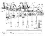
種々の図を通して同じ参照符号が同じ要素を示す図面を参照すると、図1は、上述のガスタービンエンジンの一部である高圧圧縮機10の一部分を示している。圧縮機10は、中心軸線「A」の周りで回転するように取り付けられた軸方向に細長い環状スプール12を含む。環状スプール12は、複数のより小さい構成要素から構築することができる。これによれば、スプール12は、1つ又はそれ以上のドラム部分14と、複数の環状ディスク16を含み、これら全てが一体として共に回転する。スプール12は半断面で示しているが、このスプール12は回転体であることは理解されるであろう。スプール12の外周部で複数のブレード列が担持される。各ブレード列は、スプール12から半径方向外向きに延びた環状アレイの翼形部形圧縮機ブレード18を含む。環状ライナ組立体20が圧縮機ブレード18を密接に囲み、圧縮機10を通る一次ガス流路の半径方向外側境界部を形成する。ライナ組立体20は、複数のより小さい構成要素から構成され、その一部を以下でより詳細に説明する。環状ケーシング22は、ライナ組立体20を囲み、該ライナ組立体20に構造的支持を与える。ライナ組立体20によって幾つかのステータ列が担持される。各ステータ列は、ライナ組立体20から半径方向内向きに延びた環状アレイの翼形部形ステータベーン24を含む。ステータ列は、軸方向にブレード列と交互配置される。各ブレード列及び軸方向下流ステータ列は、圧縮機10の「段」を構成する。作動時には、圧縮機10は、(図の左側から)空気を吸込み、この空気を図の右側に向かって軸方向下流側に圧送する時に加圧する。各段は、空気の増分的圧力上昇をもたらし、最終段の出口にて最高圧力になる。
Referring to the drawings wherein like reference numerals indicate like elements throughout the various views, FIG. 1 illustrates a portion of a
図示の実施例では、圧縮機10の段の一部だけが示されている。図示の前方及び後方の段は、本発明にとって重要なものではない。図示の段は、「S1」から[S7]まで順次的に表記されている。これらの個数は、参照を容易にするために使用されているに過ぎず、圧縮機10全体における実際の段数に必ずしも対応していない。図の左側(圧縮機10の入口端部に向かって)に示されるS1からS4までの4つの段には、可変ステータベーンすなわち略して「VSV」が組み込まれており、これらの段のステータベーン24は、その入射角が作動中に変更できる(すなわち、これらのステータベーン24は、破線で示した半径方向軸線の周りで枢動することができる)ように構成されている。図の右側(圧縮機の出口端部に向かって)の残りの段には、VSVが組み込まれていない。本発明の原理は一般に、段の総数に関係なく、或いは幾つの段がVSVを含んでいるかに関係なく、VSVの2つ又はそれ以上の軸方向に隣接する段を有するあらゆる軸流圧縮機に適用可能である。VSVにより、公知の方法で圧縮機10を通る流れの流量調整が可能になり、その結果、圧縮機10は、高及び低質量流量の両方で効率的に作動することができる。S1からS4までの各段のステータベーン24は、対応するトラニオン(全体的に「26」と称され、それぞれ26Aから26Dで表記されている)を有しており、このトラニオンはライナ組立体20及びケーシング22を貫通して半径方向外向きに延びている。各トラニオン26A〜26Dの遠位端部には、アクチュエータアーム(全体的に「28」と称され、それぞれ28Aから28Dで表記されている)が取り付けられている。個々の段におけるアクチュエータアーム28A〜28Dの全ては、リング30(全体的に「30」と称され、それぞれ30Aから30Dで表記されている)によって一体的に結合されている。これにより、エンジンの長手方向軸線Aの周りのリング30A〜30Dの回転により、特定のリング30A〜30Dに結合されたアクチュエータアーム28の全てを一体となって移動させ、その結果としてトラニオン26A〜26Dの全てをその取り付けステータベーンと共に一体となって枢動させる。
In the illustrated embodiment, only a portion of the stage of the
この特定の実施例では、個々のスロットの環状アレイを含むことができる後方抽気スロット32は、段S6の後方のライナ組立体20を貫通している。後方抽気スロット32は、ライナ組立体20とケーシング22との間に形成された後方プレナム36と連通している。ケーシング22における1つ又はそれ以上の抽出ポート38は、後方プレナム36から空気を抽出するための場所を提供する。使用時には、後方抽出ポート38は、ケーシング22(図示せず)の外部にある適切な配管又はダクトに結合されることになる。
In this particular embodiment, a
個々のスロットの環状アレイを含むことができる中央抽気スロット40は、段S3の後方のライナ組立体20を貫通している。中央抽気スロット40は、ライナ組立体20とケーシング22との間に形成され且つ後方プレナム36から隔離された中央プレナム42と連通している。ケーシング22における1つ又はそれ以上の中央抽出ポート44は、中央プレナム42から空気を抽出するための場所を提供する。使用時には、この抽出ポート44は、ケーシング22(図示せず)の外部にある適切な配管又はダクトに結合されることになる。
A central bleed slot 40, which can include an annular array of individual slots, passes through the
個々のスロットの環状アレイを含むことができる前方抽気スロット46は、段S1の後方のライナ組立体20を貫通している。前方抽気スロット46は、ライナ組立体20とケーシング22との間に形成され且つ後方プレナム36及び中央プレナム42から隔離された前方プレナム48と連通している。ケーシング22内における1つ又はそれ以上の前方抽出ポート50は、前方プレナム48から空気を抽出する場所を提供する。使用時には、この抽出ポート50は、ケーシング22(図示せず)の外部にある適切な配管又はダクトに結合されることになる。
A
図2は、段S1と段S2との間で空気を抽気するために使用される構造体をより詳細に示している。環状シュラウド52は、上述のように圧縮機ブレード18を囲む。シュラウド52は、リング内に配置された複数のセグメントで構成されて完全な360度の組立体を形成することができる。シュラウドセグメントは、前方レール54及び後方レール56を含み、これらをライナ組立体20の隣接する部分のスロット内に取り付けることができる。上述の前方抽気スロット46は、シュラウド52内に形成され且つ前方プレナム48と連通している。この特定の実施例では、前方抽気スロット46は、前方レール54とシュラウド52のほぼテーパ状の円筒形中央部分58との間に配置される。典型的な構造体は、セグメントのリングから構成されるライナ組立体20と、2つのセクションで形成され割線フランジ60にて一体的にボルト締めされたケーシング22とを有することになる。これらの構成要素間の接合部にて漏洩を防止するために、第3のプレナム48内にダクト62を位置付けることができる。1つの実施例として、ダクト62は、シュラウド52と抽出ポート50との間に流路を形成した前方壁64及び後方壁64を有することができる。ダクト62は、完全な環状形状に組み立てられた2つ又はそれ以上のアーチ形セグメントで作ることができる。
FIG. 2 shows in more detail the structure used to bleed air between stages S1 and S2. The
前方プレナム48は、VSVを有する2つの段間で軸方向に位置している。段S1から空気を抽気し且つ該空気を前方プレナム48から抽出するのに十分な空間を提供するために、VSVの動作ハードウェアは、従来技術の実施におけるものとは異なって位置付けられる。具体的には、段S1のアクチュエータアーム28Bは軸方向前方に延びているが、段S2のアクチュエータアーム28Cは軸方向後方に延びている。本明細書で使用する場合に、「軸方向に」という用語は、図1に示した長手方向軸線Aと平行な方向を意味している。これにより、ケーシング22の外側寄りに図2において破線で示された開放空隙「V」が形成され、これは従来技術構成においては存在しない。開放空隙「V」により、外部配管又はダクト(図示せず)を抽出ポート50に接続することが可能になる。
The
作動時には、段S1、S3、及びS6から空気を抽気して、空気流を3つの個別の圧力で供給することができる。可能な限り多量のブリード空気が最低可能圧力(すなわち、可能な最前方の段)で抽出されて、効率及び燃料消費率(「SFC」)に与える影響を最小限にするようになる。従来技術の抽気構成とは対照的に、このような圧力がVSV段の場所で見られるということにも拘わらず、所望の圧力で空気を抽出することができる。 In operation, air can be extracted from stages S1, S3, and S6 to provide an air flow at three separate pressures. As much of the bleed air as possible is extracted at the lowest possible pressure (ie, the foremost stage possible) so as to minimize the impact on efficiency and fuel consumption (“SFC”). In contrast to the prior art bleed configuration, air can be extracted at the desired pressure despite such pressure being found at the VSV stage location.
ケーシング及びライナが単一壁に組み込まれる圧縮機110において同様の空気抽気構成を実装することができる。例えば、図3は、スプール112、圧縮機ブレード118、及びステータベーン124を有する圧縮機の一部分を示している。環状ケーシング122は、圧縮機ブレード118を囲み、ステータベーン用のマウントとして、及び圧縮機ブレード118のシュラウドとしての両方の役割を果たす。事実上、環状ケーシング122は、1つの一体形ユニットとして上述のケーシング及びライナ組立体を含む。ステータベーン124の一部は可変角度(すなわち、VSV)であり、それぞれアクチュエータアーム128A〜128Dに結合されたトラニオン126A〜126D及びリング130を含む。説明の目的で、2つの軸方向に隣接する段のステータベーン124を説明する。S1´で表記された1つの段は、トラニオン126A、アクチュエータアーム128A、及びリング130Aを含む。段S1´のすぐ下流に位置する段S2´は、トラニオン126B、アクチュエータアーム128B、及びリング130Bを含む。アクチュエータアーム128Aは、軸方向前方に延び、アクチュエータアーム128Bは、軸方向後方に延びて、破線で示した「空隙」を形成する。抽気スロット146は、ケーシング122を貫通して形成され、プレナム148と連通している。空間V´が存在することに起因して、プレナム148は、適切な配管又はダクトワーク(図示せず)と結合することができる。
A similar air bleed configuration can be implemented in the
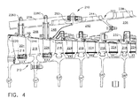
図4は、圧縮機から空気を抽気するための代替の構成を示している。この図は、上述のガスタービンエンジンの一部であり且つその全体的な構成が圧縮機10に類似している高圧圧縮機210の一部分を示しており、圧縮機10と同の構成要素を省略して説明する。圧縮機210は、圧縮機ブレード218のブレード列を備えた環状スプール212を含む。環状ライナ組立体220は、圧縮機ブレード218を緊密に囲み、圧縮機210を貫通する一次ガス流路の半径方向外側境界部を形成する。ライナ組立体220は、複数のより小さい構成要素から構成され、その一部を以下でより詳細に説明する。環状ケーシング222は、ライナ組立体220を囲み、ステータベーン224の複数のステータ列を有する。
FIG. 4 shows an alternative configuration for extracting air from the compressor. This figure shows a portion of a high-
この図示の実施例では、「S1´´」から「S6´´」で表記された圧縮機210の段の一部のみを示している。上述のように、これらの個数は、参照を容易にするために使用されているに過ぎず、圧縮機10全体における実際の段数に必ずしも対応していない。図示の第1の3つの段(すなわち、S1´´〜S3´´)は、上述のように可変ステータベーンを組み込んでいる。各段S1´´からS3´´までのベーン224は、対応するトラニオン(それぞれ226Aから226Cで表記されている)を有しており、このトラニオンはライナ組立体220及びケーシング222を貫通して半径方向外向きに延びている。トラニオン226A〜226Cの作動ハードウェアは図示していない。
In the illustrated embodiment, only a part of the stage of the
個々のスロットの環状アレイを含むことができる後方抽気スロット232は、段S5´´の後方のライナ組立体220を貫通している。後方抽気スロット232は、ライナ組立体220とケーシング222との間に形成された後方プレナム236と連通している。ケーシング222における1つ又はそれ以上の後方抽出ポート238は、後方プレナム236から空気を抽出するための場所を提供する。使用時には、後方抽出ポート238は、ケーシング222の外部にある適切な配管又はダクト(図示せず)に結合されることになる。
A
個々のスロットの環状アレイを含むことができる中央抽気スロット240は、段S2´´の後方のライナ組立体220を貫通している。中央抽気スロット240は、ライナ組立体220とケーシング222との間に形成され且つ後方プレナム236から隔離された中央プレナム242と連通している。ケーシング222における1つ又はそれ以上の中央抽出ポート244は、中央プレナム242から空気を抽出するための場所を提供する。使用時には、中央抽出ポート244は、ケーシング222の外部にある適切な配管又はダクト(図示せず)に結合されることになる。
A
個々のスロットの環状アレイを含むことができる前方抽気スロット246は、段S1´´の後方のライナ組立体220を貫通している。前方抽気スロット246は、ライナ組立体220とケーシング222との間に形成され且つ後方プレナム236及び中央プレナム242から隔離された前方プレナム248と連通している。ケーシング222における1つ又はそれ以上の前方抽出ポート250は、前方プレナム248から空気を抽気する場所を提供する。使用時には、この前方抽出ポート250は、ケーシング222の外部にある適切な配管又はダクトに結合されることになる。
A
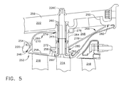
図5は、段S1から空気を抽気するために使用される構造体をより詳細に示している。上述のように、環状シュラウド252は、圧縮機ブレード218を囲む。シュラウド252は、リング内に配置された複数のセグメントから構成されて完全な360度組立体を形成することができる。シュラウドセグメントは、前方レール254及び後方レール256を含み、これらをライナ組立体220の周囲部分のスロット内に取り付けることができる。上述の前方抽気スロット246は、シュラウド252内に形成され且つ前方プレナム248と連通している。この特定の実施例では、前方抽気スロット246は、前方レール254とシュラウド252のほぼテーパ状の円筒形中央部分258との間に配置される。
FIG. 5 shows in more detail the structure used to bleed air from stage S1. As described above, the
トラニオン226Cを受けるブッシュ260は、ケーシング222の一部である環状壁様ボス262を貫通している。段S5を越えてブリード空気を通過させるために、ボス262は、アパーチャ264の近くのその周辺部周りの複数の場所で貫通される。図6において、アパーチャ264と、該アパーチャを越えて延びているトラニオンとを見ることができる。任意選択的に、トラニオン226Cは、隣接するトラニオン226間の横方向の空間を増大させ、これによりアパーチャ264を通してより多くの流れを可能にするために、図7に見られるように、軸方向よりも円周方向においてより小さい軸方向に細長い非円形状を有することができる。任意選択的に、トラニオン226とケーシング222との間のブリード空気の漏洩を防止するために、アパーチャ264において半径方向に延びるトラニオン226を囲むように中空スリーブ265を位置付けることができる。
A
前方プレナム248を通る漏洩を防止するために、様々な手段を用いることができる。上述のように、典型的な構成は、セグメントのリングから構成されるライナ組立体220と、2つのセクションで形成されて割線フランジ259にて一体的にボルト締めされたケーシング222とを有することになる。これらの構成要素間の接合部にて漏洩を防止するために、前方プレナム248内に環状前方ダクト266及び後方ダクト268を位置付けることができる。前方ダクト266は、L字形状断面を備えたアーチ形外側壁270及び内側壁272を含む。内側壁270及び外側壁272は全体として、シュラウド252とボス262の前面274との間に流路を形成する。後方ダクト268は、ほぼU字形状断面を備えた外側壁276と、ある角度をなして後方及び半径方向外向きに延びたほぼ線形断面を備えた内側壁278とを含む。内側壁278及び外側壁276は全体として、ボス262の後方面280とケーシング222の内側表面282との間に流路を形成する。前方ダクト266及び後方ダクト268の両方は、完全な環状形状として組み立てられた2つ又はそれ以上のアーチ形セグメントから作ることができる。
Various means can be used to prevent leakage through the
上述の抽気構成は、あらゆる所望の抽気位置において必要に応じて組み合わせ及び/又は適合させることができる。特定の圧縮機は、VSV段又は非VSV段の何れかの内部に1つ又は複数の抽気位置を有することができる。可変段の後方に抽気ポートを配置することにより、圧縮機長さが維持され且つVSVの複雑さを最小限になると共に、キャビティから直接抽気することにより抽気システム/漏洩損失が減少する。従来技術の抽気構成とは対照的に、圧縮機内部の軸方向位置に関係なく、所望の圧力で空気を抽出することができる。本明細書で説明した抽気構成は、エンジンSFCの大幅な低減をもたらすことができると思われる。 The bleed configurations described above can be combined and / or adapted as needed at any desired bleed location. Certain compressors may have one or more bleed positions within either the VSV stage or the non-VSV stage. By placing the bleed port behind the variable stage, the compressor length is maintained and VSV complexity is minimized, while bleed system / leakage loss is reduced by bleed directly from the cavity. In contrast to prior art bleed configurations, air can be extracted at a desired pressure regardless of the axial position within the compressor. It is believed that the bleed configuration described herein can provide a significant reduction in engine SFC.
以上の説明は、ガスタービンエンジン圧縮機における抽気構成について述べてきた。本発明の特定の実施形態を説明してきたが、本発明の技術的思想及び範囲から逸脱することなく種々の修正形態を実施できることは、当業者であれば理解されるであろう。従って、本発明は、上述の説明によって限定されると見なすべきではなく、添付の請求項の範囲によってのみ限定される。 The above description has described the bleed configuration in a gas turbine engine compressor. While specific embodiments of the present invention have been described, those skilled in the art will recognize that various modifications can be made without departing from the spirit and scope of the invention. Accordingly, the invention is not to be seen as limited by the foregoing description, but is only limited by the scope of the appended claims.
10 圧縮機
12 スプール
14 ドラム部分
16 ディスク
18 圧縮機ブレード
20 ライナ組立体
22 ケーシング
24 ステータベーン
26 トラニオン
28 アクチュエータアーム
30 リング
32 後方抽気スロット
36 後方プレナム
38 後方抽出ポート
40 中央抽気スロット
42 中央プレナム
44 中央抽出ポート
46 前方抽気スロット
48 前方プレナム
50 前方抽出ポート
52 シュラウド
54 前方レール
56 後方レール
58 中央部分
60 割線フランジ
62 ダクト
64 前方壁
66 後方壁
110 圧縮機
112 スプール
118 圧縮機ブレード
122 ケーシング
124 ステータベーン
126 トラニオン
128 アクチュエータアーム
130 リング
146 抽気スロット
210 圧縮機
212 スプール
218 ブレード
220 ライナ組立体
222 ケーシング
226 トラニオン
232 後方抽気スロット
236 後方プレナム
238 後方抽出ポート
240 中央抽気スロット
242 中央プレナム
244 中央抽出ポート
246 前方抽気スロット
248 前方プレナム
250 前方抽出ポート
252 シュラウド
254 前方レール
256 後方レール
258 中央部分
260 ブッシュ
262 ボス
264 アパーチャ
265 スリーブ
266 前方ダクト
268 後方ダクト
270 外側壁
272 内側壁
274 前面
276 内側壁
278 外側壁
280 後面
282 内面
DESCRIPTION OF
Claims (5)
中心軸線の周りで回転するように取り付けられ且つ翼形部形圧縮機ブレード(18、118、218)の環状アレイを各々が備えた複数の軸方向に離間したブレード列を担持する圧縮機スプール(12、112、212)と、
前記圧縮機ブレード(18、118、218)を囲み、且つ前記圧縮機を貫通する一次ガス流路の境界部を形成したライナ組立体(20、220)を担持するケーシング(22、122、222)と、
前記ライナ組立体(20、220)によって担持され且つ各々が翼形部形ステータベーン(24、124、224)の環状アレイを含む複数の軸方向に離間したステータ列と、
を備え、
前記ステータ列が前記ブレード列と軸方向に交互配置され、前記ステータ列の少なくとも幾つかの軸方向に隣接する列が可変ステータ列であり、該ステータ列のステータベーン(24、124、224)が前記ケーシング(22、122、222)を貫通するトラニオン(26、126、226)上に取り付けられて、前記ケーシング(22、122、222)に対して枢動可能になっており、
前記圧縮機装置が更に、前記ケーシング(22、122、222)の外側で前記トラニオン(26、126、226)の各々に結合されたアクチュエータアーム(28、128)を備え、
前記複数の可変ステータ列の第1の列のアクチュエータアーム(28、128)が、軸方向前方に延び、
前記複数の可変ステータ列の、前記第1の列と軸方向後方で隣接する第2の列のアクチュエータアーム(28、128)が軸方向後方に延びて、前記ケーシング(22、122、222)の外部において少なくとも1つの第1の抽気スロット(46、146、246)とほぼ軸方向に整列した開放空隙を形成するようになっており、
前記少なくとも1つの第1の抽気スロット(46、146、246)は、 前記可変ステータ列の前記第1及び第2の列の間で前記ライナ組立体(20、220)を貫通し、
前記圧縮機装置が更に、前記ケーシング(22、122、222)によって形成され且つ前記少なくとも1つの第1の抽気スロット(46、146、246)及び前記ケーシング(22、122、222)の外部と連通している第1の流路を備え、
前記ケーシング(22、122、222)が、前記第1の流路と流れ連通した状態で前記ケーシング(22、122、222)の外部表面にて形成され且つ前記開放空隙の前方及び後方境界部内に軸方向に位置付けられた少なくとも1つの第1の抽出ポート(50、250)を含む、
装置。 A compressor device,
Compressor spool carrying a plurality of axially spaced blade rows each mounted to rotate about a central axis and each comprising an annular array of airfoil compressor blades (18, 118, 218) 12, 112, 212),
A casing (22, 122, 222) carrying a liner assembly (20, 220) surrounding the compressor blade (18, 118, 218) and forming a boundary of a primary gas flow path penetrating the compressor When,
A plurality of axially spaced stator rows carried by the liner assembly (20, 220) and each including an annular array of airfoil stator vanes (24, 124, 224);
With
The stator rows are arranged alternately with the blade rows in the axial direction, at least some of the stator rows adjacent in the axial direction are variable stator rows, and the stator vanes (24, 124, 224) of the stator rows are provided. Mounted on a trunnion (26, 126, 226) passing through the casing (22, 122, 222) and pivotable relative to the casing (22, 122, 222);
The compressor device further comprises an actuator arm (28, 128) coupled to each of the trunnions (26, 126, 226) outside the casing (22, 122, 222);
Actuator arms (28, 128) of a first row of the plurality of variable stator rows extend axially forward;
Of the plurality of variable stator column, the first of the second row of actuator arm adjacent columns and axially aft (28, 128) is extending axially rearward, the casing (22, 122, 222) Forming an open gap substantially axially aligned with at least one first bleed slot (46, 146, 246) on the outside;
The at least one first bleed slot (46, 146, 246) extends through the liner assembly (20, 220) between the first and second rows of the variable stator row;
The compressor apparatus is further formed by the casing (22, 122, 222) and in communication with the at least one first bleed slot (46, 146, 246) and the outside of the casing (22, 122, 222). A first flow path,
The casing (22, 122, 222) is formed on the outer surface of the casing (22, 122, 222) in flow communication with the first flow path and in the front and rear boundaries of the open gap Including at least one first extraction port (50, 250) axially positioned;
apparatus.
前記少なくとも1つの付加的な抽気スロット(32、40、232、240)及び前記ケーシング(22、122、222)の外部表面に配置された少なくとも1つの付加的な抽出ポート(38、44、238、244)と連通するケーシング(22、122、222)によって形成され、且つ前記第1の流路から隔離されている第2の流路と、
を更に備える、請求項1乃至4のいずれか1項に記載の装置。
記載の装置。
At least one additional bleed slot (32, 40, 232, 240) passing through the liner assembly (20, 220) downstream in the axial direction of all of the variable stator rows;
The at least one additional bleed slot (32, 40, 232, 240) and at least one additional extraction port (38, 44, 238, disposed on the outer surface of the casing (22, 122, 222); 244) a second flow path formed by a casing (22, 122, 222) in communication with and isolated from the first flow path;
The apparatus according to claim 1, further comprising:
The device described.
Applications Claiming Priority (2)
| Application Number | Priority Date | Filing Date | Title |
|---|---|---|---|
| US13/094,934 | 2011-04-27 | ||
| US13/094,934 US8734091B2 (en) | 2011-04-27 | 2011-04-27 | Axial compressor with arrangement for bleeding air from variable stator vane stages |
Publications (3)
| Publication Number | Publication Date |
|---|---|
| JP2012233476A JP2012233476A (en) | 2012-11-29 |
| JP2012233476A5 JP2012233476A5 (en) | 2015-05-21 |
| JP6105208B2 true JP6105208B2 (en) | 2017-03-29 |
Family
ID=46084830
Family Applications (1)
| Application Number | Title | Priority Date | Filing Date |
|---|---|---|---|
| JP2012098293A Expired - Fee Related JP6105208B2 (en) | 2011-04-27 | 2012-04-24 | Axial compressor with device for extracting air from variable stator vane stage |
Country Status (4)
| Country | Link |
|---|---|
| US (1) | US8734091B2 (en) |
| EP (1) | EP2518273A3 (en) |
| JP (1) | JP6105208B2 (en) |
| CA (1) | CA2775423A1 (en) |
Families Citing this family (22)
| Publication number | Priority date | Publication date | Assignee | Title |
|---|---|---|---|---|
| US9988915B2 (en) * | 2013-03-13 | 2018-06-05 | United Technologies Corporation | Stator segment |
| JP6185781B2 (en) * | 2013-07-23 | 2017-08-23 | 三菱日立パワーシステムズ株式会社 | Axial flow compressor |
| US9657647B2 (en) | 2013-10-15 | 2017-05-23 | The Boeing Company | Methods and apparatus to adjust bleed ports on an aircraft engine |
| EP2881548B1 (en) * | 2013-12-09 | 2018-08-15 | MTU Aero Engines GmbH | Gas turbine compressor |
| EP3084142B1 (en) * | 2013-12-16 | 2019-01-02 | United Technologies Corporation | Shortened support for compressor variable vane |
| EP2960438B1 (en) | 2014-06-26 | 2020-09-02 | MTU Aero Engines GmbH | Variable guide vane device for a gas turbine and gas turbine equipped with such a device |
| US10612416B2 (en) | 2014-09-05 | 2020-04-07 | United Technologies Corporation | Offtakes for gas turbine engine secondary gas flows |
| GB2552426A (en) | 2015-03-31 | 2018-01-24 | Halliburton Energy Services Inc | Actuator controlled variable flow area stator for flow splitting in down-hole tools |
| US10215047B2 (en) | 2015-12-28 | 2019-02-26 | General Electric Company | Actuation system utilizing MEMS technology |
| US10302019B2 (en) | 2016-03-03 | 2019-05-28 | General Electric Company | High pressure compressor augmented bleed with autonomously actuated valve |
| US10731663B2 (en) * | 2016-06-21 | 2020-08-04 | Rolls-Royce North American Technologies Inc. | Axial compressor with radially outer annulus |
| CN106194846A (en) * | 2016-07-12 | 2016-12-07 | 中国航空工业集团公司沈阳发动机设计研究所 | A kind of double-layered case structure compressor and there is its aero-engine |
| US11073160B2 (en) | 2016-09-08 | 2021-07-27 | The United States Of America As Represented By The Secretary Of The Army | Adaptable articulating axial-flow compressor/turbine rotor blade |
| US10539153B2 (en) | 2017-03-14 | 2020-01-21 | General Electric Company | Clipped heat shield assembly |
| US20180313364A1 (en) * | 2017-04-27 | 2018-11-01 | General Electric Company | Compressor apparatus with bleed slot including turning vanes |
| US10934943B2 (en) * | 2017-04-27 | 2021-03-02 | General Electric Company | Compressor apparatus with bleed slot and supplemental flange |
| US10626879B2 (en) * | 2017-11-13 | 2020-04-21 | United Technologies Corporation | Gas turbine engine with mid-compressor bleed |
| US10794272B2 (en) * | 2018-02-19 | 2020-10-06 | General Electric Company | Axial and centrifugal compressor |
| DE102018113997A1 (en) * | 2018-06-12 | 2019-12-12 | Rolls-Royce Deutschland Ltd & Co Kg | Housing arrangement for an axial compressor of a gas turbine engine |
| US11866182B2 (en) | 2020-05-01 | 2024-01-09 | General Electric Company | Fuel delivery system having a fuel oxygen reduction unit |
| US11512611B2 (en) * | 2021-02-09 | 2022-11-29 | General Electric Company | Stator apparatus for a gas turbine engine |
| US11781504B2 (en) * | 2021-10-19 | 2023-10-10 | Honeywell International Inc. | Bleed plenum for compressor section |
Family Cites Families (19)
| Publication number | Priority date | Publication date | Assignee | Title |
|---|---|---|---|---|
| US3996964A (en) * | 1972-09-15 | 1976-12-14 | The Bendix Corporation | Control apparatus particularly for a plurality of compressor bleed valves of a gas turbine engine |
| US3945759A (en) | 1974-10-29 | 1976-03-23 | General Electric Company | Bleed air manifold |
| DE2740904A1 (en) * | 1977-09-10 | 1979-03-22 | Motoren Turbinen Union | DEVICE FOR OPERATING SHUT-OFF ELEMENTS IN GAS TURBINE ENGINES, IN PARTICULAR GAS TURBINE JET |
| US4791783A (en) * | 1981-11-27 | 1988-12-20 | General Electric Company | Convertible aircraft engine |
| FR2601074B1 (en) * | 1986-07-03 | 1990-05-25 | Snecma | TURBOMACHINE PROVIDED WITH A DEVICE FOR CONTROLLING THE VENTILATION AIR FLOW TAKEN FOR THE CONTROL OF THE GAMES BETWEEN ROTOR AND STATOR. |
| DE3940248A1 (en) * | 1989-04-17 | 1990-10-18 | Gen Electric | METHOD AND DEVICE FOR REGULATING A GAS TURBINE ENGINE |
| US5155993A (en) | 1990-04-09 | 1992-10-20 | General Electric Company | Apparatus for compressor air extraction |
| US5209633A (en) | 1990-11-19 | 1993-05-11 | General Electric Company | High pressure compressor flowpath bleed valve extraction slot |
| US6109868A (en) | 1998-12-07 | 2000-08-29 | General Electric Company | Reduced-length high flow interstage air extraction |
| US6325595B1 (en) | 2000-03-24 | 2001-12-04 | General Electric Company | High recovery multi-use bleed |
| US6413043B1 (en) * | 2000-11-09 | 2002-07-02 | General Electric Company | Inlet guide vane and shroud support contact |
| US6438941B1 (en) * | 2001-04-26 | 2002-08-27 | General Electric Company | Bifurcated splitter for variable bleed flow |
| US6550254B2 (en) | 2001-08-17 | 2003-04-22 | General Electric Company | Gas turbine engine bleed scoops |
| US6783324B2 (en) * | 2002-08-15 | 2004-08-31 | General Electric Company | Compressor bleed case |
| FR2858027B1 (en) * | 2003-07-21 | 2005-09-23 | Snecma Moteurs | HIGH PRESSURE COMPRESSOR WITH A HYBRID CYCLE AND TURBOMACHINE COMPRISING SUCH A COMPRESSOR |
| US7624581B2 (en) | 2005-12-21 | 2009-12-01 | General Electric Company | Compact booster bleed turbofan |
| FR2916815B1 (en) * | 2007-05-30 | 2017-02-24 | Snecma | AIR REINJECTION COMPRESSOR |
| US8388308B2 (en) * | 2007-10-30 | 2013-03-05 | General Electric Company | Asymmetric flow extraction system |
| EP2058524A1 (en) * | 2007-11-12 | 2009-05-13 | Siemens Aktiengesellschaft | Air bleed compressor with variable guide vanes |
-
2011
- 2011-04-27 US US13/094,934 patent/US8734091B2/en active Active
-
2012
- 2012-04-19 CA CA2775423A patent/CA2775423A1/en not_active Abandoned
- 2012-04-24 JP JP2012098293A patent/JP6105208B2/en not_active Expired - Fee Related
- 2012-04-26 EP EP12165786.0A patent/EP2518273A3/en not_active Withdrawn
Also Published As
| Publication number | Publication date |
|---|---|
| EP2518273A3 (en) | 2017-04-19 |
| US8734091B2 (en) | 2014-05-27 |
| CA2775423A1 (en) | 2012-10-27 |
| US20120275912A1 (en) | 2012-11-01 |
| JP2012233476A (en) | 2012-11-29 |
| EP2518273A2 (en) | 2012-10-31 |
Similar Documents
| Publication | Publication Date | Title |
|---|---|---|
| JP6105208B2 (en) | Axial compressor with device for extracting air from variable stator vane stage | |
| US11448235B2 (en) | Axi-centrifugal compressor with variable outlet guide vanes | |
| JP6043370B2 (en) | Gas turbine engine sump pressurization system | |
| US20180328187A1 (en) | Turbine engine with an airfoil and insert | |
| US7077623B2 (en) | Fluid flow machine with integrated fluid circulation system | |
| US11221017B2 (en) | Method and system for integrated pitch control mechanism actuator hydraulic fluid transfer | |
| US7631484B2 (en) | High pressure ratio aft fan | |
| JP4588306B2 (en) | Aircraft gas turbine engine with non-intermeshing counter-rotating low pressure turbine | |
| US8789354B2 (en) | Gas turbine engine with separate core and propulsion unit | |
| JP2017096269A (en) | Gas turbine engine fan | |
| US8955304B2 (en) | Gas turbine engine with modular cores and propulsion unit | |
| JP2017110640A (en) | Endwall treatment with venturi effect | |
| JP2017072136A (en) | Engine having variable pitch outlet guide vanes | |
| JP2016109124A (en) | Axial compressor endwall treatment for controlling leakage flow | |
| JP2017078410A (en) | Method and system for modulated turbine cooling | |
| US10760426B2 (en) | Turbine engine with variable effective throat | |
| JP2017096268A (en) | Variable pitch fan actuator | |
| US20180306123A1 (en) | Annular airflow actuation system for variable cycle gas turbine engines | |
| US9822792B2 (en) | Assembly for a fluid flow machine | |
| US10060286B2 (en) | Geared annular airflow actuation system for variable cycle gas turbine engines | |
| CN112443364B (en) | Actuating assembly for concentric variable stator vanes | |
| EP3019716A1 (en) | Angled core engine | |
| US20230304415A1 (en) | Clearance control system for a gas turbine engine | |
| US11933193B2 (en) | Turbine engine with an airfoil having a set of dimples | |
| US11401835B2 (en) | Turbine center frame |
Legal Events
| Date | Code | Title | Description |
|---|---|---|---|
| A521 | Written amendment |
Free format text: JAPANESE INTERMEDIATE CODE: A523 Effective date: 20150406 |
|
| A621 | Written request for application examination |
Free format text: JAPANESE INTERMEDIATE CODE: A621 Effective date: 20150406 |
|
| A977 | Report on retrieval |
Free format text: JAPANESE INTERMEDIATE CODE: A971007 Effective date: 20160128 |
|
| A131 | Notification of reasons for refusal |
Free format text: JAPANESE INTERMEDIATE CODE: A131 Effective date: 20160202 |
|
| A601 | Written request for extension of time |
Free format text: JAPANESE INTERMEDIATE CODE: A601 Effective date: 20160425 |
|
| A601 | Written request for extension of time |
Free format text: JAPANESE INTERMEDIATE CODE: A601 Effective date: 20160630 |
|
| A521 | Written amendment |
Free format text: JAPANESE INTERMEDIATE CODE: A523 Effective date: 20160801 |
|
| TRDD | Decision of grant or rejection written | ||
| A01 | Written decision to grant a patent or to grant a registration (utility model) |
Free format text: JAPANESE INTERMEDIATE CODE: A01 Effective date: 20170207 |
|
| A61 | First payment of annual fees (during grant procedure) |
Free format text: JAPANESE INTERMEDIATE CODE: A61 Effective date: 20170302 |
|
| R150 | Certificate of patent or registration of utility model |
Ref document number: 6105208 Country of ref document: JP Free format text: JAPANESE INTERMEDIATE CODE: R150 |
|
| LAPS | Cancellation because of no payment of annual fees |