EP2518171A1 - Aluminum alloy for anodization and aluminum alloy component - Google Patents
Aluminum alloy for anodization and aluminum alloy component Download PDFInfo
- Publication number
- EP2518171A1 EP2518171A1 EP10839310A EP10839310A EP2518171A1 EP 2518171 A1 EP2518171 A1 EP 2518171A1 EP 10839310 A EP10839310 A EP 10839310A EP 10839310 A EP10839310 A EP 10839310A EP 2518171 A1 EP2518171 A1 EP 2518171A1
- Authority
- EP
- European Patent Office
- Prior art keywords
- mass
- aluminum alloy
- crystals
- series
- base metal
- Prior art date
- Legal status (The legal status is an assumption and is not a legal conclusion. Google has not performed a legal analysis and makes no representation as to the accuracy of the status listed.)
- Granted
Links
Images



Classifications
-
- C—CHEMISTRY; METALLURGY
- C22—METALLURGY; FERROUS OR NON-FERROUS ALLOYS; TREATMENT OF ALLOYS OR NON-FERROUS METALS
- C22F—CHANGING THE PHYSICAL STRUCTURE OF NON-FERROUS METALS AND NON-FERROUS ALLOYS
- C22F1/00—Changing the physical structure of non-ferrous metals or alloys by heat treatment or by hot or cold working
- C22F1/04—Changing the physical structure of non-ferrous metals or alloys by heat treatment or by hot or cold working of aluminium or alloys based thereon
- C22F1/05—Changing the physical structure of non-ferrous metals or alloys by heat treatment or by hot or cold working of aluminium or alloys based thereon of alloys of the Al-Si-Mg type, i.e. containing silicon and magnesium in approximately equal proportions
-
- C—CHEMISTRY; METALLURGY
- C22—METALLURGY; FERROUS OR NON-FERROUS ALLOYS; TREATMENT OF ALLOYS OR NON-FERROUS METALS
- C22C—ALLOYS
- C22C21/00—Alloys based on aluminium
-
- C—CHEMISTRY; METALLURGY
- C22—METALLURGY; FERROUS OR NON-FERROUS ALLOYS; TREATMENT OF ALLOYS OR NON-FERROUS METALS
- C22C—ALLOYS
- C22C21/00—Alloys based on aluminium
- C22C21/02—Alloys based on aluminium with silicon as the next major constituent
-
- C—CHEMISTRY; METALLURGY
- C22—METALLURGY; FERROUS OR NON-FERROUS ALLOYS; TREATMENT OF ALLOYS OR NON-FERROUS METALS
- C22F—CHANGING THE PHYSICAL STRUCTURE OF NON-FERROUS METALS AND NON-FERROUS ALLOYS
- C22F1/00—Changing the physical structure of non-ferrous metals or alloys by heat treatment or by hot or cold working
- C22F1/04—Changing the physical structure of non-ferrous metals or alloys by heat treatment or by hot or cold working of aluminium or alloys based thereon
-
- C—CHEMISTRY; METALLURGY
- C25—ELECTROLYTIC OR ELECTROPHORETIC PROCESSES; APPARATUS THEREFOR
- C25D—PROCESSES FOR THE ELECTROLYTIC OR ELECTROPHORETIC PRODUCTION OF COATINGS; ELECTROFORMING; APPARATUS THEREFOR
- C25D11/00—Electrolytic coating by surface reaction, i.e. forming conversion layers
- C25D11/02—Anodisation
- C25D11/04—Anodisation of aluminium or alloys based thereon
-
- F—MECHANICAL ENGINEERING; LIGHTING; HEATING; WEAPONS; BLASTING
- F16—ENGINEERING ELEMENTS AND UNITS; GENERAL MEASURES FOR PRODUCING AND MAINTAINING EFFECTIVE FUNCTIONING OF MACHINES OR INSTALLATIONS; THERMAL INSULATION IN GENERAL
- F16D—COUPLINGS FOR TRANSMITTING ROTATION; CLUTCHES; BRAKES
- F16D65/00—Parts or details
- F16D65/14—Actuating mechanisms for brakes; Means for initiating operation at a predetermined position
- F16D65/16—Actuating mechanisms for brakes; Means for initiating operation at a predetermined position arranged in or on the brake
- F16D65/18—Actuating mechanisms for brakes; Means for initiating operation at a predetermined position arranged in or on the brake adapted for drawing members together, e.g. for disc brakes
-
- F—MECHANICAL ENGINEERING; LIGHTING; HEATING; WEAPONS; BLASTING
- F16—ENGINEERING ELEMENTS AND UNITS; GENERAL MEASURES FOR PRODUCING AND MAINTAINING EFFECTIVE FUNCTIONING OF MACHINES OR INSTALLATIONS; THERMAL INSULATION IN GENERAL
- F16D—COUPLINGS FOR TRANSMITTING ROTATION; CLUTCHES; BRAKES
- F16D2125/00—Components of actuators
- F16D2125/02—Fluid-pressure mechanisms
- F16D2125/06—Pistons
-
- F—MECHANICAL ENGINEERING; LIGHTING; HEATING; WEAPONS; BLASTING
- F16—ENGINEERING ELEMENTS AND UNITS; GENERAL MEASURES FOR PRODUCING AND MAINTAINING EFFECTIVE FUNCTIONING OF MACHINES OR INSTALLATIONS; THERMAL INSULATION IN GENERAL
- F16D—COUPLINGS FOR TRANSMITTING ROTATION; CLUTCHES; BRAKES
- F16D2200/00—Materials; Production methods therefor
- F16D2200/0004—Materials; Production methods therefor metallic
- F16D2200/0026—Non-ferro
- F16D2200/003—Light metals, e.g. aluminium
Definitions
- the present invention relates to an aluminum alloy suitable for anodization, and also relates to an aluminum alloy component having an anodic oxide film.
- a brake piston of aluminum alloy is employed to attain high-performance and low-fuel consumption.
- the cup-shaped brake piston 1 shown in Fig. 1 is one example thereof (see Patent Document No. 1).
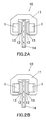
- Fig. 2A shows a disk brake 10 in a brake-off state
- Fig. 2B shows a disk brake in a brake-on state.
- the disk brake 10 when a liquid pressure is applied to an inside of a cylinder of a caliper 11 in which the brake piston 1 is accommodated, the open end portion of the brake piston 1 presses a back plate 13 of a friction pad 12, causing a contact of the friction pad 12 with the brake disk 14, which in turn results in a braking action.
- the aforementioned cup-shaped brake piston can be produced by, for example, extruding a billet, drawing the extruded member into a bar-shaped member, subjecting the bar-shaped drawn member to solution treatment, subjecting the solution treated member to aging treatment to attain desired mechanical strength, and then machining the aged member into a cup-shape.
- it can be produced by, for example, casting a bar-shaped member of aluminum alloy, cutting the cast member into a predetermined thickness, forging the cut member into a cup-shape, subjecting the cup-shaped forged member to T6 treatment, and then machining the T6 treated forged member to improve the dimensional accuracy and remove distortion caused during the solution treatment (see Patent Document No. 2).
- the brake piston is a sliding member. Therefore, the brake piston is required to have material strength and wear resistance capable of preventing deformation during the brake operation, and also is required to have machinability during the production and smoothness of the sliding surface to attain smooth braking when in use.
- high-strength and high-wear and abrasion resistance aluminum alloy in which elements, such as, e.g., Cu, Mn, and/or Cr, are added to an Al-Si series alloy or an Al-Mg-Si series alloy is used.
- an anodic oxide film is formed on the alloy (see Patent Documents Nos. 2-4) .
- an Al alloy suitable for anodization an Al-Fe series alloy used as an architectural material or a cap material for a beverage bottle is known (Patent Documents Nos. 5-7).
- Patent Documents 2 and 3 describe that strength of an anodic oxide film is influenced by the existence state of Si particles.
- an aluminum alloy for a brake piston or an aluminum alloy for anodization it can be considered to use Al-Si series alloys, Al-Mg-Si series alloys, or Al-Fe series alloys.
- Al-Si series alloys Al-Mg-Si series alloys
- Al-Fe series alloys Al-Fe series alloys
- Al-Si series alloys are high in material strength as aging alloy and excellent in detachability of chips during a cutting work due to functions of eutectic Si particles contained in the base metal.
- eutectic Si particles in the base metal cause severe abrasion of a cutting tool.
- a larger additive amount of Si in the base metal has a beneficial effect on crack prevention of an anodic oxide film, but causes deterioration of surface smoothness of a film since eutectic Si particles prevent even growth of a film.
- Al-Mg-Si series alloys are high in material strength as aging alloy and causes less abrasion of a cutting tool as compared with Al-Si series alloys since no eutectic Sir particles exist in the base metal, but the alloys are poor in detachability of chips.
- Al-Mg-Si series alloys are better in surface smoothness of an anodic oxide film as compared with Al-Si series alloys, but may causes deep cracks which reaches from the film surface to the base metal since no eutectic Si particle exists in the film.
- Al-Fe series alloys are aluminum alloy for anodization but not aging alloy, and therefore they are lower in strength than Al-Si series alloys or Al-Mg-Si series alloys, which cannot meet strength required for a brake piston.
- the present invention was made in view of the aforementioned technical background, and aims to provide an aluminum alloy capable of creating an anodic oxide film high in surface smoothness, which is improved in strength as compared with conventional Al-Fe series alloys, reduced in abrasion of a cutting tool while keeping its excellent cutting performance, and causes less crack generation.
- the present invention also aims to provide an aluminum alloy component having an anodic oxide film.
- the present invention has a structure as recited in the following [1] to [4].
- An aluminum alloy for anodization consisting of Fe: 0.5 to 2 mass%, Cu: 0.35 to 0. 6 mass%, Mg: 0. 35 to 1.3 mass%, Si: 0.2 to 1.3 mass%, Cr: 0.05 to 0.3 mass%, Mn: 0.05 to 0.3 mass%, Ti: 0.005 to 0.1 mass%, and the balance being inevitable impurities, wherein Zn is controlled to be less than 0.25 mass%.
- a production method of an aluminum alloy component comprising: age hardening a base metal constituted by an aluminum alloy consisting of Fe: 0.5 to 2 mass%, Cu: 0.35 to 0.6 mass%, Mg: 0.35 to 1.3 mass%, Si: 0.2 to 1.3 mass%, Cr: 0.05 to 0.3 mass%, Mn: 0.05 to 0.3 mass%, Ti: 0.005 to 0.1 mass%, and the balance being inevitable impurities, wherein Zn is controlled to be less than 0.25 mass%; and thereafter anodizing the base metal to form an anodic film.
- the aluminum alloy as recited in the aforementioned Item [1] although it is an Al-Fe series alloy, it becomes possible to attain age hardening by the added Cu, Mg, and Si. High strength can be attained by heat treatment. Further, the Al-Fe series crystals and Al-Fe-Si series crystals crystallized during casting solidification have hardness which enhances detachability of chips. However, the hardness is lower than that of Si particles crystallized in Al-Si series alloys, and therefore cutting tool abrasion can be reduced than Al-Si series alloys.
- Al-Fe series crystals and Al-Fe-Si series crystals remain in the film without being dissolved, causing an existence of these crystals in a dispersed manner. This enables creation of an anodic oxide film which causes less cracks due to the dispersed crystals.
- the base metal is constituted by the aluminum alloy as recited in the aforementioned Item [1]. Therefore, high strength exerted by age hardening due to the chemical composition of the base metal alloy, and excellent machinability and tool abrasion reduction effect due to Al-Fe series crystals and Al-Fe-Si series crystals can be obtained.
- minute Al-Fe series crystals and Al-Fe-Si series crystals having a maximum grain diameter of 30 ⁇ m or less exist in an evenly dispersed manner with an average center-to-center distance of 10 to 100 ⁇ m, and a percentage of occupied area of these crystals in the anodic oxide film is 5% or more. Therefore, these crystals absorb stress caused by the difference of linear coefficient of expansion between the base metal and the film during the anodization, resulting in less crack generation. Further, crystals are minute and exist evenly, which causes even growth of the film. As a result, a film high in surface smoothness can be formed.
- the aluminum alloy of the present invention is an aluminum alloy for anodization capable of creating an anodic oxide film excellent in property, which is enhanced in properties of a base metal by defining its chemical component and dispersing minute Al-Fe series crystals and Al-Fe-Si series crystals derived from the base metal during anodization in a film.
- Fe is an element which creates Al-Fe series crystals and Al-Fe-Si series crystals during the casting solidification.
- the inventor found the fact that the growth of cracks in a film was suppressed by the existence of Al-Fe series crystals and/or Al-Fe-Si series crystals. Based on the findings, by creating Al-Fe series crystals and/or Al-Fe-Si series crystals so as to suppress crack growth as taught by the present invention, an anodic oxide film causing less cracks can be obtained.
- the aforementioned Al-Fe series crystals and Al-Fe-Si series crystals remain unsolved in an anodic oxide film at the time of anodization, reducing crack generation of the film.
- the Fe concentration in the alloy is set to 0.5 to 2 mass%. If it is less than 0.5 mass%, the amount of created crystals becomes insufficient to reduce crack generation. If it exceeds 2 mass%, coarse crystals (example, the maximum grain diameter of 100 ⁇ m) will be generated at the time of casting the base metal, which exerts an adverse influence on mechanical property (elongation) of the base metal. Furthermore, since crystals created during the casting remain in the anodic oxide film, if the crystals are coarse, the surface smoothness of the film deteriorates.
- the preferable Fe concentration is 0.7 to 1.7 mass%.
- Cu is an element which contributes to enhancement of strength of the base metal, and the Cu concentration in the alloy is set to 0.35 to 0.6 mass%.
- a brake piston has strength of 300 N/mm 2 or more, which can be attained by adding Cu. If the Cu concentration is less than 0.35 %, less contribution to enhancement of strength can be attained. If it exceeds 0. 6 mass%, Cu creates Al-Cu-Fe series crystals together with Fe, which decreases the creation amount of Al-Fe series crystals and Al-Fe-Si series crystals effective to decrease crack generation. On the other hand, the Al-Cu-Fe series crystals are dissolved at the time of anodization, which does not contribute to reduction of crack generation. As a result, an excessive amount of Cu reduces an amount of crystals which contributes to reduction of crack generation of the film.
- the preferable Cu concentration is 0.4 to 0.5 mass%.
- Mg is an element to be added to enhance the strength of the base metal by being precipitated as Mg 2 Si in the matrix.
- the Mg concentration in the alloy is set to 0.35 to 1.3 mass%. If Mg concentration is less than 0.35 %, less strength enhancement effect can be obtained. If it exceeds 1.3 mass%, crystals will be formed together with Si, reducing the amount of Mg 2 Si to be precipitated, which deteriorates contribution to strength enhancement.
- the preferable Mg concentration is 0.4 to 1.2 mass%.
- Si is an element to be added to precipitate Mg 2 Si in the matrix to thereby enhance the strength of the base metal, and the Si concentration in the alloy is set to 0.2 to 1.3 mass%. If the Si concentration is less than 0.2 mass%, less strength enhancement effect can be attained. If it exceeds 1.3 mass%, Si creates crystals together with Mg, resulting in less amount of Mg 2 Si to be precipitated, which deteriorates contribution to strength enhancement.
- the preferable Si concentration is 0.4 to 1.2 mass%.
- Cr is an element to be added to miniaturize recrystallized particles after the hot processing or during the solution heat treatment of the base metal to thereby enhance the strength of the base metal.
- the Cr concentration in the alloy is set to 0.05 to 0.3 mass%. If the Cr concentration is less than 0.05 mass%, less miniaturization effect of recrystallized particles can be attained, resulting in less contribution to enhancement of the strength. Even if it exceeds 0.3 mass%, the effect will be saturated. Further, the excess amount of Cr increases the precipitation density of a chemical compound with Al in the matrix, resulting in deteriorated quenching property.
- the preferable Cr concentration is 0.1 to 0.2 mass%.
- Mn is an element, in the same manner as Cr, to be added to miniaturize recrystallized particles after the hot processing or during the solution heat treatment of the base metal to thereby enhance the strength of the base metal.
- the Mn concentration in the alloy is set to 0.01 to 0.3 mass%. If the Mn concentration is less than 0.01 mass%, less miniaturization effect of recrystallized particles can be attained, resulting in less contribution to enhancement of the strength. Even if it exceeds 0.3 mass%, the effect will be saturated. Further, the excess amount of Mn increases the precipitation density of a chemical compound with Al in the matrix, resulting in deteriorated quenching property.
- Mn creates crystals with Fe, Si and/or Cu, which reduces the creation amount of Al-Fe series crystals and Al-Fe-Si series crystals effective to reduce crack generation.
- the crystals with Fe, Si, and/or Cu are dissolved at the time of the anodization treatment, which does not contribute to reduction of crack generation.
- the excessive amount of Mn decreases the amount of crystals which contribute to reduction of crack generation of the film.
- the preferable Mn concentration is 0.01 to 0.1 mass%.
- Ti is an element to be added to miniaturize crystal grains during the casting solidification of the base metal.
- the Ti concentration in the alloy is set to 0.005 to 0.1 mass%. If Ti concentration is less than 0.005 mass%, less miniaturization effect can be attained. Even if it is added to exceed 0.1 mass%, the effect will be saturated.
- the preferable Ti concentration is 0.01 to 0.05 mass%.
- Zn is an element contained as impurities in a material ingot, but if the Zn concentration in the alloy exceeds a certain value, the characteristics of the anodic oxide film deteriorate, which in turn may cause deterioration of corrosion resistance of the base metal. For this reason, the Zn concentration is controlled to be less than 0.25 mass%. In the aluminum alloy containing Mg and Si, the potential of Zn becomes base, causing dissolution of Zn during the anodization, which results in a more porous film. For this reason, when the Zn concentration is 0.25 mass% or more, the anodized member may cause acid corrosion or the like. The preferable Zn concentration is less than 0.1 mass%. If it is tried to reduce the Zn concentration as much as possible, the cost for purifying the material ingot increases. Therefore, in the present invention, the Zn concentration is set to less than 0.25 mass% considering the cost performance.
- An aluminum alloy component according to the present invention is a component in which an anodic oxide film is formed on a surface of a base metal of the aluminum alloy having the aforementioned chemical composition.
- the aluminum alloy constituting the base metal is Al-Fe series alloy
- the alloy can be age-hardened by adding Mg and Si, and the strength of the base metal can be enhanced by heat treatment.
- a conventionally known Al-Fe series alloy in which no such elements are added, no age-hardening is exerted, which is not appropriate for the use as a sliding component due to lack of strength.
- the alloy of the present invention although the alloy is Al-Fe series alloy, the alloy can be age-hardened and satisfies the strength required for a sliding member.
- the Al-Fe series crystals and the Al-Fe-Si series crystals crystalized in the base metal are particles sufficient enough to become starting points for detaching the chips. Therefore, the detachability of chips is excellent, which is sufficient enough to improve the machinability as compared with 6000 series alloys.
- the Al-Fe series crystals and the Al-Fe-Si series crystals are lower in hardness than Si particles crystalized in Al-Si series alloys, which causes less abrasion of a cutting tool than Al-Si series alloys.
- a degree of machinability of the alloy and a degree of abrasion of a cutting tool are in between 6000 series alloys and Al-Si series alloys, which are both preferably balanced.
- the anodic oxide film includes minute Al-Fe series crystals and Al-Fe-Si series crystals in a dispersed manner.
- the Al-Fe series crystals and the Al-Fe-Si series crystals are minute particles/grains having a maximum diameter of 30 ⁇ m or less and dispersed evenly with an average center-to-center distance of 10 to 100 ⁇ m.
- the center-to-center distance of crystals is defined by the distance L1, L2, ..., and Ln between the center of one of crystal particles/grains 21 dispersed in the anodic oxide film 20 and the center of another crystal particles/grains 21 existing around the one of crystal particles/grains 21, and the average center-to-center distance is defined by an average value thereof.
- the amount of crystals in the film is 5% or more in the percentage of the total occupied area of the Al-Fe series crystals and the Al-Fe-Si series crystals in the anodic oxide film. It is preferable that the occupied area of the eutectic Si particles to be crystallized is almost nothing and the percentage of the occupied area is 1% or less.
- the percentage of the occupied area is a percentage occupied by crystals when a cross-sectional view taken in a thickness direction of the film is observed and represented by the following formula.
- the observation view can be magnified 100 to 400 times with an optical microscope.
- the Al-Fe series crystals and the Al-Fe-Si series crystals are elements derived from the base metal and remained in the film without being dissolved during the anodization. It is assumed that these crystals absorb stress caused by the difference of linear coefficient of expansion between the base metal and the film during the anodization to thereby reduce crack generation. Such effect can be obtained when minute crystal grains having the maximum grain diameter of 30 ⁇ m or less are dispersed evenly with the average center-to-center distance of 10 to 100 ⁇ m and the percentage of occupied area in the film is 5% or more. The crystal grains are minute and dispersed evenly, causing even growth of the film, which results in creation of a film having high-surface smoothness.
- the preferable maximum grain diameter of the Al-Fe series crystals and the Al-Fe-Si series crystals is 25 ⁇ m or less, more preferably 3 to 15 ⁇ m.
- the preferable center-to-center distance of the Al-Fe series crystals and the Al-Fe-Si series crystals is 20 to 50 ⁇ m, and the preferable percentage of occupied area is 5 to 25%.
- the thickness of the anodic oxide film is not specifically limited, but it is recommended that a thickness meeting abrasion resistance required for a sliding component such as a brake piston is 30 to 50 ⁇ m. Furthermore, the surface smoothness of the anodic oxide film is not specifically limited, but the preferable surface roughness R(z) of a sliding component is 1.5 ⁇ m or less, more preferably 0.2 to 1.3 ⁇ m.
- An aluminum alloy component of the present invention is produced by forming a base metal for anodization having a predetermined shape and strength using the aluminum alloy having the aforementioned composition and forming an anodic oxide film on a surface of the base metal by performing anodization.
- a cup-shaped brake piston 1 to be mounted on a disk brake 10 as shown in Figs. 1 , 2A and 2B is produced through a series of steps shown in Fig. 4 .
- an ingot material is dissolved and continuously cast into a bar-shape, and then cut into a predetermined length to obtain a billet.
- the billet is subjected to soaking treatment and machine finish. Thereafter, it is heated, extruded and then drawn. The drawn member is corrected and then sliced to thereby obtain a forging material.
- This forging material has a volume corresponding to the weight of a forged product.
- the forging material is subjected to preliminary lubrication as a pretreatment.
- the preliminary lubrication is a pretreatment for preventing seizure to a mold during the forging to attain a smooth surface of the forged product, and can be chemical film forming treatment, such as, e.g., bonderizing treatment.
- the pretreated material is subjected to cold forging to form a cup-shape.
- the cold forged member is subjected to solution treatment and then age hardening to exert strength. Required portions are cut by mechanical processing to improve the surface smoothness and the size accuracy.
- a base metal for anodization having a predetermined shape and strength is produced.
- the base metal is subjected to anodization to create an anodic oxide film to thereby obtain an aluminum alloy component.
- the strength of the base metal can be enhanced by solution treatment after cold forging and the subsequent age hardening.
- solution treatment, quenching treatment, and/or artificial aging treatment are performed.
- the cold forged component In order to obtain strength required for a brake piston, it is preferable to hold the cold forged component at 500 to 580 °C for 1 hour or more, more preferably 1.5 to 5 hours as solution treatment for a cold forged component and thereafter to quench the solution treated component by submerging into water or forcibly cooling with air as quenching treatment. In the subsequent artificial aging, it is preferable to hold it at 170 to 230 °C for 1 hour or more, more preferably 1.5 to 10 hours.
- the Al-Fe series crystals and Al-Fe-Si series crystals in the anodic oxide film are derived from the component of the base metal and crystals thereof, in order to minutely and evenly disperse such particles in a film, it is necessary that the Al-Fe series crystals and Al-Fe-Si series crystals are minutely and evenly dispersed in the base metal.
- the production conditions of the base metal which exert influence on the existence state of crystals in the anodic oxide film are a cooling rate at the continuous casting and the extrusion ratio at the extrusion.
- the preferable conditions for obtaining the maximum grain diameter of 30 ⁇ m or less of crystals in the anodic oxide film and the average center-to-center distance of 10 to 100 ⁇ m of crystals and the percentage of crystal occupied area of 5% or more are a cooling rate of 3 to 15 °C/sec. and an extrusion ratio of 10 to 70 at the continuous casting.
- the extrusion ratio is defined by a ratio of (a container cross-sectional area of an extruding apparatus) /(product cross-sectional area). In the case of performing a drawing step, it is preferable that the cross-sectional area decrease ratio represented by the following formula is 2 to 15%.
- Cross-sectional area decrease ratio (%) [(A-B)/A] x 100 where A is a cross-sectional area before drawing, and B is a cross-sectional area after drawing.
- the production steps of the base metal are not limited to the flow shown in Fig. 4 .
- the drawing step can be omitted, or the correction step can be omitted.
- the steps from the extrusion to the machining process can be replaced by the steps of "extrusion" ⁇ "cutting" ⁇ ” solution treatments" ⁇ "quenching" ⁇ "forming by machining process.”
- conditions of the anodization are not specifically limited, and the anodization can be performed by well-known steps under well-known conditions depending on the intended end-usage of the component.
- the brake piston 1 is a sliding component, a hard anodic oxide film is formed. For example, degreasing, etching, water washing, neutralization, anodization, water washing, and sealing treatment are performed sequentially.
- cup-shaped brake pistons each having an anodic oxide film on a surface of the base metal were produced in accordance with the steps shown in Fig. 4 .
- the alloys in Comparative Examples 1 and 2 were Al-Si series alloys.
- the alloys in Comparative Example 4 was a 6082 Al alloy.
- the alloys in Examples 5 and 6 were Al-Fe series alloys.
- a bar having a diameter of 210 mm was continuously casted at the casting temperature of 710 °C +/-10 °C, the casting rate of 120 mm/min, and the cooling rate of 7 °C/sec. in accordance with a hot-top continuous casting method.
- the bar was held at 540 °C for 7 hours.
- the bar was machine finished from a diameter of 210 mm to a diameter of 203 mm, and cut into a length of 800 mm to obtain a billet.
- the billet was pre-heated to 350 °C.
- the billet was extruded into a round bar having a diameter of 44 mm at an extrusion speed (product speed) of 7.3 mm/min.
- the extrusion ratio in this extrusion was 22.7.
- the extruded member having a diameter of 44 mm was drawn into a diameter of 43.2 mm.
- the area decreasing rate in this drawing was 3.6%.
- the drawn member was annealed at 370 °C for 4 hours.
- the annealed member was preliminary lubricated by bonderization treatment.
- the preliminary lubricated member was formed into a cup-shape by one pressing of closed die forging.
- the cup-shaped member was held at 540 °C for 3 hours, and then quenched by water cooling.
- the solution treated and quenched member was held at 180 °C for 7 hours.
- the age hardened member was machined.
- the base metal was subjected to anodization.
- degreasing by immersion in an acid bath, water washing, neutralization by immersion in an alkaline bath, water washing, anodization by immersion in a 15 wt% sulfuric bath, water washing, and sealing by immersion in a hot water were performed sequentially.
- anodic oxide film having a thickness of 37 ⁇ m was created.
- the maximum diameter of the Al-Fe series crystals and the Al-Fe-Si series crystals existed in the film, the average center-to-center distance of the crystals, the percentage of occupied area of crystals, and the occupied area ratio of the eutectic Si particles were investigated as follows.
- a film cross-sectional sample was created from the anodized member and the microstructure of the cross-section was observed with an optical microscope (400 times).
- the crystals and eutectic Si particles were approximated into a true circle having the same position of the center of gravity and the same area. Based on the approximation, the maximum grain diameter, the average center-to-center distance of the crystals, the percentage of occupied area of crystals, and the percentage of occupied area of the eutectic Si particles were calculated.
- the tensile strength of the base metal was denoted as follows:
- the machinability was denoted as follows based on the incidence rate of tangles of chips on a product during the machining:
- the tool abrasiveness was denoted as follows:
- the surface smoothness was denoted as follows:
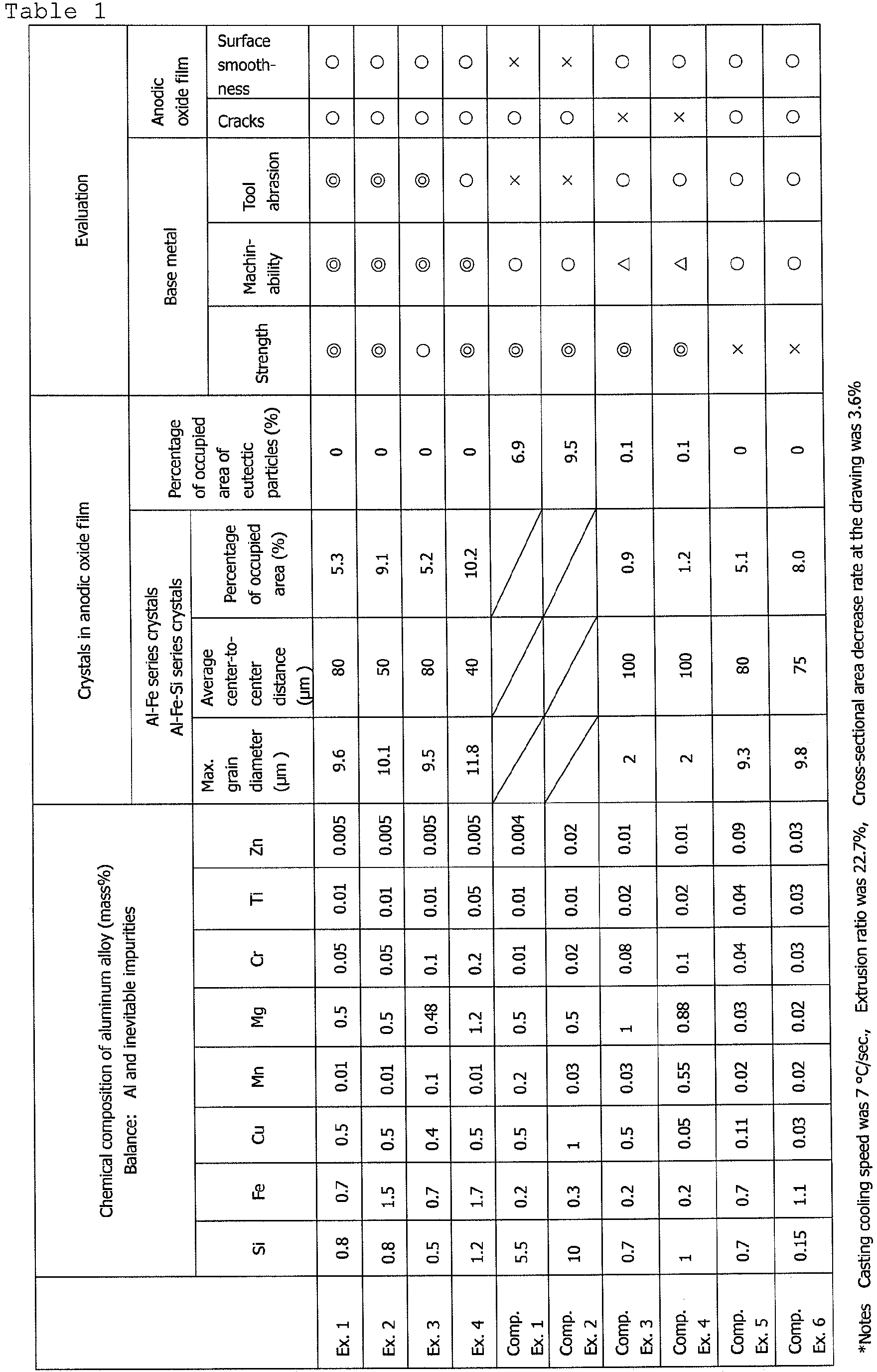
- Tables 1 and 2 reveal that the brake pistons of Examples 1 to 4 were small in tool abrasion regardless of the high strength and good machinability. No cracks reached the base metal were generated in the film, and the surface smoothness was good. Also in Examples 5 and 6, no cracks reached the base metal were generated in the film.
- Comparative Examples 1 and 2 since a large amount of eutectic Si particles high in hardness existed, hard particles existed closely. Therefore, the tool abrasion performance and the surface smoothness were poor.
- Comparative Examples 3 and 4 since the amount of crystals was small, the machinability was poor, and large cracks reached the base metal were generated.
- Comparative Examples 5 and 6 since the amount of elements (Cu, Mg) which contributes to age hardening, the strength was poor.
- Comparative Example 7 since the grain diameter of crystals was small and the amount of crystals remained in the film was reduced, large cracks reached the base metal were generated.
- Comparative Example 8 the maximum grain diameter of crystals was large and the distance between grains/particles was small, and therefore large cracks reached the base metal were generated.
- the aluminum alloy of the present invention can be utilized in producing a sliding component required to have strength and abrasion resistance.
Landscapes
- Chemical & Material Sciences (AREA)
- Engineering & Computer Science (AREA)
- Materials Engineering (AREA)
- Metallurgy (AREA)
- Organic Chemistry (AREA)
- Mechanical Engineering (AREA)
- Chemical Kinetics & Catalysis (AREA)
- Electrochemistry (AREA)
- Physics & Mathematics (AREA)
- Thermal Sciences (AREA)
- Crystallography & Structural Chemistry (AREA)
- General Engineering & Computer Science (AREA)
- Pistons, Piston Rings, And Cylinders (AREA)
- Braking Arrangements (AREA)
- Other Surface Treatments For Metallic Materials (AREA)
Abstract
Description
- The present invention relates to an aluminum alloy suitable for anodization, and also relates to an aluminum alloy component having an anodic oxide film.
- In recent years, in a disk brake for a vehicle, such as, e.g., a four-wheel vehicle or a two-wheel vehicle, a brake piston of aluminum alloy is employed to attain high-performance and low-fuel consumption. The cup-
shaped brake piston 1 shown inFig. 1 is one example thereof (see Patent Document No. 1). -
Fig. 2A shows adisk brake 10 in a brake-off state, andFig. 2B shows a disk brake in a brake-on state. In thedisk brake 10, when a liquid pressure is applied to an inside of a cylinder of acaliper 11 in which thebrake piston 1 is accommodated, the open end portion of thebrake piston 1 presses aback plate 13 of afriction pad 12, causing a contact of thefriction pad 12 with thebrake disk 14, which in turn results in a braking action. - The aforementioned cup-shaped brake piston can be produced by, for example, extruding a billet, drawing the extruded member into a bar-shaped member, subjecting the bar-shaped drawn member to solution treatment, subjecting the solution treated member to aging treatment to attain desired mechanical strength, and then machining the aged member into a cup-shape. Alternatively, it can be produced by, for example, casting a bar-shaped member of aluminum alloy, cutting the cast member into a predetermined thickness, forging the cut member into a cup-shape, subjecting the cup-shaped forged member to T6 treatment, and then machining the T6 treated forged member to improve the dimensional accuracy and remove distortion caused during the solution treatment (see Patent Document No. 2).
- The brake piston is a sliding member. Therefore, the brake piston is required to have material strength and wear resistance capable of preventing deformation during the brake operation, and also is required to have machinability during the production and smoothness of the sliding surface to attain smooth braking when in use.
- For the material of such a brake piston, high-strength and high-wear and abrasion resistance aluminum alloy in which elements, such as, e.g., Cu, Mn, and/or Cr, are added to an Al-Si series alloy or an Al-Mg-Si series alloy is used. In order to improve the wear resistance and the corrosion resistance, an anodic oxide film is formed on the alloy (see Patent Documents Nos. 2-4) . As an aluminum alloy suitable for anodization, an Al-Fe series alloy used as an architectural material or a cap material for a beverage bottle is known (Patent Documents Nos. 5-7).
- Patent Documents 2 and 3 describe that strength of an anodic oxide film is influenced by the existence state of Si particles.
-
- [Patent Document 1] Japanese Unexamined Laid-open Patent Application Publication No.
2002-70902 JP-2002-70902, A - [Patent Document 2] Japanese Unexamined Laid-open Patent Application Publication No.
2004-232087 JP-2004-232087, A - [Patent Document 3] Japanese Unexamined Laid-open Patent Application Publication No.
H10-204566 JP- H10-204566, A - [Patent Document 4] Japanese Unexamined Laid-open Patent Application Publication No.
2001-59124 JP-2001-59124, A - [Patent Document 5] Japanese Unexamined Laid-open Patent Application Publication No.
2003-277989 JP-2003-277989, A - [Patent Document 6] Japanese Unexamined Laid-open Patent Application Publication No.
2003-282164 JP-2003-282164, A - [Patent Document 7] Japanese Unexamined Laid-open Patent Application Publication No.
2005-248213 JP-2005-248213, A - As explained above, as an aluminum alloy for a brake piston or an aluminum alloy for anodization, it can be considered to use Al-Si series alloys, Al-Mg-Si series alloys, or Al-Fe series alloys. However, these alloys have advantages and disadvantages.
- Al-Si series alloys are high in material strength as aging alloy and excellent in detachability of chips during a cutting work due to functions of eutectic Si particles contained in the base metal. However, eutectic Si particles in the base metal cause severe abrasion of a cutting tool. A larger additive amount of Si in the base metal has a beneficial effect on crack prevention of an anodic oxide film, but causes deterioration of surface smoothness of a film since eutectic Si particles prevent even growth of a film.
- Al-Mg-Si series alloys are high in material strength as aging alloy and causes less abrasion of a cutting tool as compared with Al-Si series alloys since no eutectic Sir particles exist in the base metal, but the alloys are poor in detachability of chips. Al-Mg-Si series alloys are better in surface smoothness of an anodic oxide film as compared with Al-Si series alloys, but may causes deep cracks which reaches from the film surface to the base metal since no eutectic Si particle exists in the film.
- Al-Fe series alloys are aluminum alloy for anodization but not aging alloy, and therefore they are lower in strength than Al-Si series alloys or Al-Mg-Si series alloys, which cannot meet strength required for a brake piston.
- The present invention was made in view of the aforementioned technical background, and aims to provide an aluminum alloy capable of creating an anodic oxide film high in surface smoothness, which is improved in strength as compared with conventional Al-Fe series alloys, reduced in abrasion of a cutting tool while keeping its excellent cutting performance, and causes less crack generation. The present invention also aims to provide an aluminum alloy component having an anodic oxide film.
- The present invention has a structure as recited in the following [1] to [4].
- [1] An aluminum alloy for anodization, consisting of Fe: 0.5 to 2 mass%, Cu: 0.35 to 0. 6 mass%, Mg: 0. 35 to 1.3 mass%, Si: 0.2 to 1.3 mass%, Cr: 0.05 to 0.3 mass%, Mn: 0.05 to 0.3 mass%, Ti: 0.005 to 0.1 mass%, and the balance being inevitable impurities, wherein Zn is controlled to be less than 0.25 mass%.
- [2] An aluminum alloy component in which an anodic oxide film is formed on a surface of a base metal of an aluminum alloy,
wherein the aluminum alloy consists of Fe: 0.5 to 2 mass%, Cu: 0. 35 to 0. 6 mass%, Mg: 0. 35 to 1.3 mass%, Si: 0.2 to 1. 3 mass%, Cr: 0.05 to 0.3 mass%, Mn: 0.01 to 0.3 mass%, Ti: 0.005 to 0.1 mass%, and the balance being inevitable impurities, wherein Zn is limited to be less than 0.25 mass%, and
wherein Al-Fe series crystals and Al-Fe-Si series crystals having a maximum grain diameter of 30 µm or less exist in the anodic oxide film in a dispersed manner with an average center-to-center distance of 10 to 100 µm, and a percentage of a total occupied area of the Al-Fe series crystals and Al-Fe-Si series crystals in the anodic oxide film is 5% or more. - [3] The aluminum alloy component as recited in the aforementioned Item [2], wherein the sliding component is a brake piston.
- [4] A production method of an aluminum alloy component, comprising:
age hardening a base metal constituted by an aluminum alloy consisting of Fe: 0.5 to 2 mass%, Cu: 0.35 to 0.6 mass%, Mg: 0.35 to 1.3 mass%, Si: 0.2 to 1.3 mass%, Cr: 0.05 to 0.3 mass%, Mn: 0.05 to 0.3 mass%, Ti: 0.005 to 0.1 mass%, and the balance being inevitable impurities, wherein Zn is controlled to be less than 0.25 mass%; and thereafter
anodizing the base metal to form an anodic film. - According to the aluminum alloy as recited in the aforementioned Item [1], although it is an Al-Fe series alloy, it becomes possible to attain age hardening by the added Cu, Mg, and Si. High strength can be attained by heat treatment. Further, the Al-Fe series crystals and Al-Fe-Si series crystals crystallized during casting solidification have hardness which enhances detachability of chips. However, the hardness is lower than that of Si particles crystallized in Al-Si series alloys, and therefore cutting tool abrasion can be reduced than Al-Si series alloys. By anodizing, Al-Fe series crystals and Al-Fe-Si series crystals remain in the film without being dissolved, causing an existence of these crystals in a dispersed manner. This enables creation of an anodic oxide film which causes less cracks due to the dispersed crystals.
- In the aluminum alloy component as recited in the aforementioned Item [2], the base metal is constituted by the aluminum alloy as recited in the aforementioned Item [1]. Therefore, high strength exerted by age hardening due to the chemical composition of the base metal alloy, and excellent machinability and tool abrasion reduction effect due to Al-Fe series crystals and Al-Fe-Si series crystals can be obtained. Furthermore, in the anodic oxide film, minute Al-Fe series crystals and Al-Fe-Si series crystals having a maximum grain diameter of 30 µm or less exist in an evenly dispersed manner with an average center-to-center distance of 10 to 100 µm, and a percentage of occupied area of these crystals in the anodic oxide film is 5% or more. Therefore, these crystals absorb stress caused by the difference of linear coefficient of expansion between the base metal and the film during the anodization, resulting in less crack generation. Further, crystals are minute and exist evenly, which causes even growth of the film. As a result, a film high in surface smoothness can be formed.
- According to the aluminum alloy component as recited in the aforementioned Item [3], the aforementioned effects can be attained in a brake piston.
- According to the production method of the aluminum alloy component as recited in the aforementioned Item [4], high strength can be exerted due to age hardening of the base material. By performing anodization after the age hardening, an aluminum alloy component as recited in the aforementioned Items [2] and [3] can be produced.
-
- [
Fig. 1] Fig. 1 is a perspective view of a brake piston. - [
Fig. 2A] Fig. 2A is a view showing a disk brake in a brake-off state. - [
Fig. 2B] Fig. 2B is a view showing the disk brake in a brake-on state. - [
Fig. 3] Fig. 3 is a view explaining center-to-center distances of crystals. - [
Fig. 4] Fig. 4 is a flowchart showing one example of production steps of an aluminum alloy component. - The aluminum alloy of the present invention is an aluminum alloy for anodization capable of creating an anodic oxide film excellent in property, which is enhanced in properties of a base metal by defining its chemical component and dispersing minute Al-Fe series crystals and Al-Fe-Si series crystals derived from the base metal during anodization in a film.
- Hereinafter, reasons for adding elements to an aluminum alloy and appropriate concentration of the elements will be detailed.
- Fe is an element which creates Al-Fe series crystals and Al-Fe-Si series crystals during the casting solidification. As a result of a keen examination of crack generation of a film, the inventor found the fact that the growth of cracks in a film was suppressed by the existence of Al-Fe series crystals and/or Al-Fe-Si series crystals. Based on the findings, by creating Al-Fe series crystals and/or Al-Fe-Si series crystals so as to suppress crack growth as taught by the present invention, an anodic oxide film causing less cracks can be obtained.
- In detail, the aforementioned Al-Fe series crystals and Al-Fe-Si series crystals remain unsolved in an anodic oxide film at the time of anodization, reducing crack generation of the film. The Fe concentration in the alloy is set to 0.5 to 2 mass%. If it is less than 0.5 mass%, the amount of created crystals becomes insufficient to reduce crack generation. If it exceeds 2 mass%, coarse crystals (example, the maximum grain diameter of 100 µm) will be generated at the time of casting the base metal, which exerts an adverse influence on mechanical property (elongation) of the base metal. Furthermore, since crystals created during the casting remain in the anodic oxide film, if the crystals are coarse, the surface smoothness of the film deteriorates. The preferable Fe concentration is 0.7 to 1.7 mass%.
- Cu is an element which contributes to enhancement of strength of the base metal, and the Cu concentration in the alloy is set to 0.35 to 0.6 mass%. For example, it is preferable that a brake piston has strength of 300 N/mm2 or more, which can be attained by adding Cu. If the Cu concentration is less than 0.35 %, less contribution to enhancement of strength can be attained. If it exceeds 0. 6 mass%, Cu creates Al-Cu-Fe series crystals together with Fe, which decreases the creation amount of Al-Fe series crystals and Al-Fe-Si series crystals effective to decrease crack generation. On the other hand, the Al-Cu-Fe series crystals are dissolved at the time of anodization, which does not contribute to reduction of crack generation. As a result, an excessive amount of Cu reduces an amount of crystals which contributes to reduction of crack generation of the film. The preferable Cu concentration is 0.4 to 0.5 mass%.
- Mg is an element to be added to enhance the strength of the base metal by being precipitated as Mg2Si in the matrix. The Mg concentration in the alloy is set to 0.35 to 1.3 mass%. If Mg concentration is less than 0.35 %, less strength enhancement effect can be obtained. If it exceeds 1.3 mass%, crystals will be formed together with Si, reducing the amount of Mg2Si to be precipitated, which deteriorates contribution to strength enhancement. The preferable Mg concentration is 0.4 to 1.2 mass%.
- Si is an element to be added to precipitate Mg2Si in the matrix to thereby enhance the strength of the base metal, and the Si concentration in the alloy is set to 0.2 to 1.3 mass%. If the Si concentration is less than 0.2 mass%, less strength enhancement effect can be attained. If it exceeds 1.3 mass%, Si creates crystals together with Mg, resulting in less amount of Mg2Si to be precipitated, which deteriorates contribution to strength enhancement. The preferable Si concentration is 0.4 to 1.2 mass%.
- Cr is an element to be added to miniaturize recrystallized particles after the hot processing or during the solution heat treatment of the base metal to thereby enhance the strength of the base metal. The Cr concentration in the alloy is set to 0.05 to 0.3 mass%. If the Cr concentration is less than 0.05 mass%, less miniaturization effect of recrystallized particles can be attained, resulting in less contribution to enhancement of the strength. Even if it exceeds 0.3 mass%, the effect will be saturated. Further, the excess amount of Cr increases the precipitation density of a chemical compound with Al in the matrix, resulting in deteriorated quenching property. The preferable Cr concentration is 0.1 to 0.2 mass%.
- Mn is an element, in the same manner as Cr, to be added to miniaturize recrystallized particles after the hot processing or during the solution heat treatment of the base metal to thereby enhance the strength of the base metal. The Mn concentration in the alloy is set to 0.01 to 0.3 mass%. If the Mn concentration is less than 0.01 mass%, less miniaturization effect of recrystallized particles can be attained, resulting in less contribution to enhancement of the strength. Even if it exceeds 0.3 mass%, the effect will be saturated. Further, the excess amount of Mn increases the precipitation density of a chemical compound with Al in the matrix, resulting in deteriorated quenching property. Mn creates crystals with Fe, Si and/or Cu, which reduces the creation amount of Al-Fe series crystals and Al-Fe-Si series crystals effective to reduce crack generation. On the other hand, the crystals with Fe, Si, and/or Cu are dissolved at the time of the anodization treatment, which does not contribute to reduction of crack generation. As a result, the excessive amount of Mn decreases the amount of crystals which contribute to reduction of crack generation of the film. The preferable Mn concentration is 0.01 to 0.1 mass%.
- Ti is an element to be added to miniaturize crystal grains during the casting solidification of the base metal. The Ti concentration in the alloy is set to 0.005 to 0.1 mass%. If Ti concentration is less than 0.005 mass%, less miniaturization effect can be attained. Even if it is added to exceed 0.1 mass%, the effect will be saturated. The preferable Ti concentration is 0.01 to 0.05 mass%.
- Zn is an element contained as impurities in a material ingot, but if the Zn concentration in the alloy exceeds a certain value, the characteristics of the anodic oxide film deteriorate, which in turn may cause deterioration of corrosion resistance of the base metal. For this reason, the Zn concentration is controlled to be less than 0.25 mass%. In the aluminum alloy containing Mg and Si, the potential of Zn becomes base, causing dissolution of Zn during the anodization, which results in a more porous film. For this reason, when the Zn concentration is 0.25 mass% or more, the anodized member may cause acid corrosion or the like. The preferable Zn concentration is less than 0.1 mass%. If it is tried to reduce the Zn concentration as much as possible, the cost for purifying the material ingot increases. Therefore, in the present invention, the Zn concentration is set to less than 0.25 mass% considering the cost performance.
- An aluminum alloy component according to the present invention is a component in which an anodic oxide film is formed on a surface of a base metal of the aluminum alloy having the aforementioned chemical composition.
- Although the aluminum alloy constituting the base metal is Al-Fe series alloy, the alloy can be age-hardened by adding Mg and Si, and the strength of the base metal can be enhanced by heat treatment. In a conventionally known Al-Fe series alloy, in which no such elements are added, no age-hardening is exerted, which is not appropriate for the use as a sliding component due to lack of strength. According to the alloy of the present invention, although the alloy is Al-Fe series alloy, the alloy can be age-hardened and satisfies the strength required for a sliding member.
- Further, the Al-Fe series crystals and the Al-Fe-Si series crystals crystalized in the base metal are particles sufficient enough to become starting points for detaching the chips. Therefore, the detachability of chips is excellent, which is sufficient enough to improve the machinability as compared with 6000 series alloys. However, the Al-Fe series crystals and the Al-Fe-Si series crystals are lower in hardness than Si particles crystalized in Al-Si series alloys, which causes less abrasion of a cutting tool than Al-Si series alloys. In other words, a degree of machinability of the alloy and a degree of abrasion of a cutting tool are in between 6000 series alloys and Al-Si series alloys, which are both preferably balanced.
- The anodic oxide film includes minute Al-Fe series crystals and Al-Fe-Si series crystals in a dispersed manner. The Al-Fe series crystals and the Al-Fe-Si series crystals are minute particles/grains having a maximum diameter of 30 µm or less and dispersed evenly with an average center-to-center distance of 10 to 100 µm. The center-to-center distance of crystals is defined by the distance L1, L2, ..., and Ln between the center of one of crystal particles/
grains 21 dispersed in theanodic oxide film 20 and the center of another crystal particles/grains 21 existing around the one of crystal particles/grains 21, and the average center-to-center distance is defined by an average value thereof. The amount of crystals in the film is 5% or more in the percentage of the total occupied area of the Al-Fe series crystals and the Al-Fe-Si series crystals in the anodic oxide film. It is preferable that the occupied area of the eutectic Si particles to be crystallized is almost nothing and the percentage of the occupied area is 1% or less. - The percentage of the occupied area (the ratio of the occupied area) is a percentage occupied by crystals when a cross-sectional view taken in a thickness direction of the film is observed and represented by the following formula. The observation view can be magnified 100 to 400 times with an optical microscope.
- Percentage of occupied area (%) = (area of crystals / area of the observed view) x 100
- The Al-Fe series crystals and the Al-Fe-Si series crystals are elements derived from the base metal and remained in the film without being dissolved during the anodization. It is assumed that these crystals absorb stress caused by the difference of linear coefficient of expansion between the base metal and the film during the anodization to thereby reduce crack generation. Such effect can be obtained when minute crystal grains having the maximum grain diameter of 30 µm or less are dispersed evenly with the average center-to-center distance of 10 to 100 µm and the percentage of occupied area in the film is 5% or more. The crystal grains are minute and dispersed evenly, causing even growth of the film, which results in creation of a film having high-surface smoothness. In reducing crack generation and obtaining a film high in surface smoothness, the preferable maximum grain diameter of the Al-Fe series crystals and the Al-Fe-Si series crystals is 25 µm or less, more preferably 3 to 15 µm. The preferable center-to-center distance of the Al-Fe series crystals and the Al-Fe-Si series crystals is 20 to 50 µm, and the preferable percentage of occupied area is 5 to 25%.
- The thickness of the anodic oxide film is not specifically limited, but it is recommended that a thickness meeting abrasion resistance required for a sliding component such as a brake piston is 30 to 50 µm. Furthermore, the surface smoothness of the anodic oxide film is not specifically limited, but the preferable surface roughness R(z) of a sliding component is 1.5 µm or less, more preferably 0.2 to 1.3 µm.
- [Production Method of Aluminum Alloy Component] An aluminum alloy component of the present invention is produced by forming a base metal for anodization having a predetermined shape and strength using the aluminum alloy having the aforementioned composition and forming an anodic oxide film on a surface of the base metal by performing anodization.
- For example, a cup-shaped
brake piston 1 to be mounted on adisk brake 10 as shown inFigs. 1 ,2A and 2B is produced through a series of steps shown inFig. 4 . - Initially, an ingot material is dissolved and continuously cast into a bar-shape, and then cut into a predetermined length to obtain a billet. The billet is subjected to soaking treatment and machine finish. Thereafter, it is heated, extruded and then drawn. The drawn member is corrected and then sliced to thereby obtain a forging material. This forging material has a volume corresponding to the weight of a forged product. The forging material is subjected to preliminary lubrication as a pretreatment. The preliminary lubrication is a pretreatment for preventing seizure to a mold during the forging to attain a smooth surface of the forged product, and can be chemical film forming treatment, such as, e.g., bonderizing treatment. The pretreated material is subjected to cold forging to form a cup-shape. The cold forged member is subjected to solution treatment and then age hardening to exert strength. Required portions are cut by mechanical processing to improve the surface smoothness and the size accuracy. Through the aforementioned steps, a base metal for anodization having a predetermined shape and strength is produced. The base metal is subjected to anodization to create an anodic oxide film to thereby obtain an aluminum alloy component.
- In the aluminum alloy component of the present invention, since the base metal is an aging alloy, the strength of the base metal can be enhanced by solution treatment after cold forging and the subsequent age hardening. By performing anodic oxide film forming processing after the age hardening, a film of the base metal high in strength can be obtained, which is preferable in terms of the strength when used as a component such as a brake piston. In order to attain the age hardening, for example, solution treatment, quenching treatment, and/or artificial aging treatment are performed. In order to obtain strength required for a brake piston, it is preferable to hold the cold forged component at 500 to 580 °C for 1 hour or more, more preferably 1.5 to 5 hours as solution treatment for a cold forged component and thereafter to quench the solution treated component by submerging into water or forcibly cooling with air as quenching treatment. In the subsequent artificial aging, it is preferable to hold it at 170 to 230 °C for 1 hour or more, more preferably 1.5 to 10 hours.
- Since the Al-Fe series crystals and Al-Fe-Si series crystals in the anodic oxide film are derived from the component of the base metal and crystals thereof, in order to minutely and evenly disperse such particles in a film, it is necessary that the Al-Fe series crystals and Al-Fe-Si series crystals are minutely and evenly dispersed in the base metal. The production conditions of the base metal which exert influence on the existence state of crystals in the anodic oxide film are a cooling rate at the continuous casting and the extrusion ratio at the extrusion. The preferable conditions for obtaining the maximum grain diameter of 30 µm or less of crystals in the anodic oxide film and the average center-to-center distance of 10 to 100 µm of crystals and the percentage of crystal occupied area of 5% or more are a cooling rate of 3 to 15 °C/sec. and an extrusion ratio of 10 to 70 at the continuous casting. The extrusion ratio is defined by a ratio of (a container cross-sectional area of an extruding apparatus) /(product cross-sectional area). In the case of performing a drawing step, it is preferable that the cross-sectional area decrease ratio represented by the following formula is 2 to 15%.
- Cross-sectional area decrease ratio (%) = [(A-B)/A] x 100
where A is a cross-sectional area before drawing, and B is a cross-sectional area after drawing. - Conditions for other steps exert less influence on the existence state of crystals in the anodic oxide film and therefore are set appropriately. Since it is sufficient that the base metal to be subjected to anodization has predetermined strength and that crystals are minutely and evenly dispersed, the production steps of the base metal are not limited to the flow shown in
Fig. 4 . For example, the drawing step can be omitted, or the correction step can be omitted. Furthermore, the steps from the extrusion to the machining process can be replaced by the steps of "extrusion" → "cutting"→" solution treatments"→"quenching"→"forming by machining process." - Furthermore, conditions of the anodization are not specifically limited, and the anodization can be performed by well-known steps under well-known conditions depending on the intended end-usage of the component. Since the
brake piston 1 is a sliding component, a hard anodic oxide film is formed. For example, degreasing, etching, water washing, neutralization, anodization, water washing, and sealing treatment are performed sequentially. - Using each of the aluminum alloys having the chemical composition shown in Table 1 as a base metal, cup-shaped brake pistons each having an anodic oxide film on a surface of the base metal were produced in accordance with the steps shown in
Fig. 4 . The alloys in Comparative Examples 1 and 2 were Al-Si series alloys. The alloys in Comparative Example 4 was a 6082 Al alloy. The alloys in Examples 5 and 6 were Al-Fe series alloys. - Conditions in each step were as follows, which were common among Examples 1 to 4 and Comparative Examples 1 to 6. The steps not described below were performed under well-known conditions. The steps were common in Examples 1 to 4 and Comparative Examples 1 to 6.
- A bar having a diameter of 210 mm was continuously casted at the casting temperature of 710 °C +/-10 °C, the casting rate of 120 mm/min, and the cooling rate of 7 °C/sec. in accordance with a hot-top continuous casting method.
- The bar was held at 540 °C for 7 hours.
- The bar was machine finished from a diameter of 210 mm to a diameter of 203 mm, and cut into a length of 800 mm to obtain a billet.
- The billet was pre-heated to 350 °C.
- The billet was extruded into a round bar having a diameter of 44 mm at an extrusion speed (product speed) of 7.3 mm/min. The extrusion ratio in this extrusion was 22.7.
- The extruded member having a diameter of 44 mm was drawn into a diameter of 43.2 mm. The area decreasing rate in this drawing was 3.6%.
- The drawn member was annealed at 370 °C for 4 hours.
- The annealed member was preliminary lubricated by bonderization treatment.
- The preliminary lubricated member was formed into a cup-shape by one pressing of closed die forging.
- The cup-shaped member was held at 540 °C for 3 hours, and then quenched by water cooling.
- The solution treated and quenched member was held at 180 °C for 7 hours.
- The age hardened member was machined.
- The base metal was subjected to anodization. In this treatment, degreasing by immersion in an acid bath, water washing, neutralization by immersion in an alkaline bath, water washing, anodization by immersion in a 15 wt% sulfuric bath, water washing, and sealing by immersion in a hot water were performed sequentially. By this anodization, an anodic oxide film having a thickness of 37 µm was created.
- With respect to the anodized members of Examples 1 and 2, the maximum diameter of the Al-Fe series crystals and the Al-Fe-Si series crystals existed in the film, the average center-to-center distance of the crystals, the percentage of occupied area of crystals, and the occupied area ratio of the eutectic Si particles were investigated as follows. A film cross-sectional sample was created from the anodized member and the microstructure of the cross-section was observed with an optical microscope (400 times). In the observed image, the crystals and eutectic Si particles were approximated into a true circle having the same position of the center of gravity and the same area. Based on the approximation, the maximum grain diameter, the average center-to-center distance of the crystals, the percentage of occupied area of crystals, and the percentage of occupied area of the eutectic Si particles were calculated.
- Furthermore, in Examples 1 to 4 and Comparative Examples 1 to 6, the strength of the base metal, the machinability, the tool abrasion, the crack generation and surface smoothness of the anodic oxide film were investigated and evaluated by the following standards. These results are also shown in Table 1.
- The tensile strength of the base metal was denoted as follows:
- ⊚: when the tensile strength was 350 N/mm2 or more;
- ○: when the tensile strength was 300 N/mm2 or more but less than 350 N/mm2; and
- ×: when the tensile strength was less than 300 N/mm2.
- The machinability was denoted as follows based on the incidence rate of tangles of chips on a product during the machining:
- ⊚: when the incidence rate was 10% or less;
- ○: when the incidence rate was 10 to 30%; and
- ×: when the incidence rate was more than 30%.
- The tool abrasiveness was denoted as follows:
- ⊚: when the Si concentration in the base metal was 1.0 mass% or less;
- ○: when the Si concentration in the base metal was more than 1.0 mass% but not larger than 1.5 mass%; and
- Δ: when the Si concentration in the base metal was more than 1.5 mass% but less than 4.5 mass%; and
- ×: when the Si concentration in the base metal was more than 4.5 mass%.
- It was denoted as follows:
- ○: when no crack created from the surface of the anodic oxide film and reached the base metal was generated; and
- ×: when cracks reached the base metal were generated.
- The surface smoothness was denoted as follows:
- ×: after treatment such as buffing after the anodization was required to use the product as a brake piston; and
- ○: no after treatment was required, and the product could be used as it was.
-
- Furthermore, as shown in Table 2, in Examples 5 and 6 and Comparative Example 7, using an aluminum alloy having the same composition as in Example 1, brake pistons were produced while changing the cooling rate of the continuous casting, the extrusion ratio, and the cross-sectional area reduction rate at the drawing, with the remaining conditions kept the same as in Example 1, and then anodized. Furthermore, in Comparative Example 8, a brake piston was produced by changing the composition of the aluminum alloy, the cooling rate of the continuous casting, the extrusion ratio, and the cross-sectional area reduction rate at the drawing, with the remaining conditions kept the same as in Example 1, and then anodized.
- With respect to the anodized product in Examples 5 and 6 and Comparative Examples 7 and 8, by the same method as in Example 1, the maximum grain diameter of the Al-Fe series crystals and Al-Fe-Si series crystals in the anodic oxide film, the average center-to-center distance of the crystals and the percentage of occupied area of the crystals were investigated. Further, with the same standards as in Example 1, the generation of cracks was evaluated.
- In Table 2, Examples 1 and 2 are shown again, and the production conditions, crystals in the anodic oxide film, and the evaluation of cracks of Examples 5 and 6 and Comparative Examples 7 and 8 are shown.
-
Table 2 Chemical composition of aluminum alloy (mass%) Balance: Al and inevitable impurities Production conditions Crystals in anodic oxide film Al-Fe series crystals Al-Fe-Si series crystals Cracks Si Fe Cu Mn Mg Cr Ti Zn Continuous casting cooling speed (°C/sec) Extrusion ratio (%) Drawing cross-sectional area reduction ratio (%) Max. grain diameter (µm) Average center-to-center distance (µm) Percentage of occupied area (%) Ex. 1 0.8 0.7 0.5 0.01 0.5 0.05 0.01 0.005 7 22.7 3.6 9.6 80 5.3 ○ Ex. 2 0.8 1.5 0.5 0.01 0.5 0.05 0.01 0.005 7 22.7 3.6 10.1 50 9.1 ○ Ex. 5 0.8 0.7 0.5 0.01 0.5 0.05 0.01 0.005 3 70 2 9.8 70 5.2 ○ Ex.6 0.8 0.7 0.5 0.01 0.5 0.05 0.01 0.005 15 10 15 9.5 75 5.2 ○ Comp. Ex. 7 0.8 0.7 0.5 0.01 0.5 0.05 0.01 0.005 50 5 1 5.0 40 5.0 × Comp. Ex. 8 0.8 1 0.03 1 0.5 0.05 0.01 0.005 1 100 10 30 10 15 × Notes: The chemical composition of the aluminum alloy in Examples 5 and 6 and Comparative Example 7 were the same as that of Example 1. - Tables 1 and 2 reveal that the brake pistons of Examples 1 to 4 were small in tool abrasion regardless of the high strength and good machinability. No cracks reached the base metal were generated in the film, and the surface smoothness was good. Also in Examples 5 and 6, no cracks reached the base metal were generated in the film.
- On the other hand, in Comparative Examples 1 and 2, since a large amount of eutectic Si particles high in hardness existed, hard particles existed closely. Therefore, the tool abrasion performance and the surface smoothness were poor. In Comparative Examples 3 and 4, since the amount of crystals was small, the machinability was poor, and large cracks reached the base metal were generated. In Comparative Examples 5 and 6, since the amount of elements (Cu, Mg) which contributes to age hardening, the strength was poor. In Comparative Example 7, since the grain diameter of crystals was small and the amount of crystals remained in the film was reduced, large cracks reached the base metal were generated. In Comparative Example 8, the maximum grain diameter of crystals was large and the distance between grains/particles was small, and therefore large cracks reached the base metal were generated.
- This application claims priority to Japanese Patent Application No.
2009-290876 filed on December 22, 2009 - It should be understood that the terms and expressions used herein are used for explanation and have no intention to be used to construe in a limited manner, do not eliminate any equivalents of features shown and mentioned herein, and allow various modifications falling within the claimed scope of the present invention.
- The aluminum alloy of the present invention can be utilized in producing a sliding component required to have strength and abrasion resistance.
-
- 1
- brake piston
- 20
- anodic oxide film
- 21
- particles/grains of Al-Fe series crystals and Al-Fe-Si series crystals
Claims (4)
- An aluminum alloy for anodization, consisting of Fe: 0.5 to 2 mass%, Cu: 0.35 to 0.6 mass%, Mg: 0.35 to 1.3 mass%, Si: 0.2 to 1.3 mass%, Cr: 0.05 to 0.3 mass%, Mn: 0.05 to 0.3 mass%, Ti: 0.005 to 0.1 mass%, and the balance being inevitable impurities, wherein Zn is controlled to be less than 0.25 mass%.
- An aluminum alloy component in which an anodic oxide film is formed on a surface of a base metal of an aluminum alloy,
wherein the aluminum alloy consists of Fe: 0.5 to 2 mass%, Cu: 0.35 to 0.6 mass%, Mg: 0.35 to 1.3 mass%, Si: 0.2 to 1.3 mass%, Cr: 0.05 to 0.3 mass%, Mn: 0.01 to 0.3 mass%, Ti: 0.005 to 0.1 mass%, and the balance being inevitable impurities, wherein Zn is controlled to be less than 0.25 mass%, and
wherein Al-Fe series crystals and Al-Fe-Si series crystals having a maximum grain diameter of 30 µm or less exist in the anodic oxide film in a dispersed manner with an average center-to-center distance of 10 to 100 µm, and a percentage of a total occupied area of the Al-Fe series crystals and Al-Fe-Si series crystals in the anodic oxide film is 5% or more. - The aluminum alloy component as recited in claim 2, wherein the sliding component is a brake piston.
- A production method of an aluminum alloy component, comprising:age hardening a base metal constituted by an aluminum alloy consisting of Fe: 0.5 to 2 mass%, Cu: 0.35 to 0.6 mass%, Mg: 0.35 to 1.3 mass%, Si: 0.2 to 1.3 mass%, Cr: 0.05 to 0.3 mass%, Mn: 0.05 to 0.3 mass%, Ti: 0.005 to 0.1 mass%, and the balance being inevitable impurities, wherein Zn is controlled to be less than 0.25 mass%; and thereafteranodizing the base metal to form an anodic film.
Applications Claiming Priority (2)
| Application Number | Priority Date | Filing Date | Title |
|---|---|---|---|
| JP2009290876 | 2009-12-22 | ||
| PCT/JP2010/072760 WO2011078080A1 (en) | 2009-12-22 | 2010-12-17 | Aluminum alloy for anodization and aluminum alloy component |
Publications (3)
| Publication Number | Publication Date |
|---|---|
| EP2518171A1 true EP2518171A1 (en) | 2012-10-31 |
| EP2518171A4 EP2518171A4 (en) | 2016-04-27 |
| EP2518171B1 EP2518171B1 (en) | 2017-07-19 |
Family
ID=44195606
Family Applications (1)
| Application Number | Title | Priority Date | Filing Date |
|---|---|---|---|
| EP10839310.9A Active EP2518171B1 (en) | 2009-12-22 | 2010-12-17 | Aluminum alloy for anodization and aluminum alloy component |
Country Status (6)
| Country | Link |
|---|---|
| US (1) | US8962163B2 (en) |
| EP (1) | EP2518171B1 (en) |
| JP (1) | JP5705744B2 (en) |
| KR (1) | KR101417549B1 (en) |
| CN (1) | CN102666894B (en) |
| WO (1) | WO2011078080A1 (en) |
Cited By (2)
| Publication number | Priority date | Publication date | Assignee | Title |
|---|---|---|---|---|
| CN104343576A (en) * | 2013-08-01 | 2015-02-11 | 日立汽车系统株式会社 | A piston of an internal combustion engine, a manufacturing method thereof, an aluminum alloy part and a manufacturing method of the aluminum alloy part |
| WO2015144303A3 (en) * | 2014-03-24 | 2016-06-02 | Constellium Extrusion Decin S.R.O. | Extruded 6xxx alloy product that is suitable for turning and has low roughness after anodisation |
Families Citing this family (29)
| Publication number | Priority date | Publication date | Assignee | Title |
|---|---|---|---|---|
| KR101423447B1 (en) * | 2010-12-22 | 2014-07-24 | 쇼와 덴코 가부시키가이샤 | Method for producing formed material for brake piston |
| DE102011053716A1 (en) * | 2011-09-16 | 2013-03-21 | Walter Ag | Cutting tool with wear detection layer |
| EP2664687B1 (en) * | 2012-05-15 | 2015-07-08 | Constellium Extrusions Decin s.r.o. | Improved free-machining wrought aluminium alloy product and manufacturing process thereof |
| CN103205587B (en) * | 2013-03-27 | 2015-06-10 | 成都阳光铝制品有限公司 | Production technology of high-strength rare earth aluminum alloy applied to automotive pedal |
| JP6045446B2 (en) * | 2013-06-18 | 2016-12-14 | 日軽金アクト株式会社 | Method for producing heat-treated Al-Mg-Si alloy with excellent appearance uniformity |
| ITTO20130855A1 (en) * | 2013-10-21 | 2015-04-22 | Itt Italia Srl | METHOD FOR OBTAINING BRAKE PADS AND ASSOCIATED BRAKE PAD |
| DE212014000273U1 (en) | 2014-08-29 | 2017-04-26 | Apple Inc. | Process for reducing the spallation of anodic oxide layers of high strength substrate alloys |
| JP6402246B2 (en) | 2014-09-12 | 2018-10-10 | ノベリス・インコーポレイテッドNovelis Inc. | Alloys for highly formed aluminum products and methods for making the same |
| US9359686B1 (en) * | 2015-01-09 | 2016-06-07 | Apple Inc. | Processes to reduce interfacial enrichment of alloying elements under anodic oxide films and improve anodized appearance of heat treatable alloys |
| US9869623B2 (en) | 2015-04-03 | 2018-01-16 | Apple Inc. | Process for evaluation of delamination-resistance of hard coatings on metal substrates |
| US10760176B2 (en) | 2015-07-09 | 2020-09-01 | Apple Inc. | Process for reducing nickel leach rates for nickel acetate sealed anodic oxide coatings |
| US10233988B2 (en) | 2015-09-23 | 2019-03-19 | Akebono Brake Industry Co., Ltd | Friction material |
| US9970080B2 (en) | 2015-09-24 | 2018-05-15 | Apple Inc. | Micro-alloying to mitigate the slight discoloration resulting from entrained metal in anodized aluminum surface finishes |
| US10711363B2 (en) | 2015-09-24 | 2020-07-14 | Apple Inc. | Anodic oxide based composite coatings of augmented thermal expansivity to eliminate thermally induced crazing |
| US10174436B2 (en) | 2016-04-06 | 2019-01-08 | Apple Inc. | Process for enhanced corrosion protection of anodized aluminum |
| US11352708B2 (en) | 2016-08-10 | 2022-06-07 | Apple Inc. | Colored multilayer oxide coatings |
| KR101712328B1 (en) * | 2016-09-02 | 2017-03-03 | 엘에스전선 주식회사 | Aluminium alloy having an excellent processibility |
| CN106191583A (en) * | 2016-09-23 | 2016-12-07 | 闻喜县瑞格镁业有限公司 | A kind of high intensity can anodic oxidation Cast aluminium alloy gold and preparation method thereof |
| JP6969568B2 (en) * | 2016-10-31 | 2021-11-24 | 住友電気工業株式会社 | Aluminum alloy wire, aluminum alloy stranded wire, covered wire, and wire with terminal |
| US11242614B2 (en) | 2017-02-17 | 2022-02-08 | Apple Inc. | Oxide coatings for providing corrosion resistance on parts with edges and convex features |
| KR102004603B1 (en) * | 2017-02-24 | 2019-07-26 | 엘에스알스코 주식회사 | Aluminium alloy having an excellent processibility |
| US12054811B2 (en) * | 2018-07-04 | 2024-08-06 | Showa Denko K.K. | Aluminum alloy member for forming fluoride film and aluminum alloy member having fluoride film |
| US11549191B2 (en) | 2018-09-10 | 2023-01-10 | Apple Inc. | Corrosion resistance for anodized parts having convex surface features |
| CN109487133B (en) * | 2018-12-29 | 2021-08-13 | 依诺威(上海)新材料科技有限公司 | Anodizable high-strength 6xxx series aluminum alloy and preparation method thereof |
| JP7358759B2 (en) * | 2019-03-27 | 2023-10-12 | 株式会社レゾナック | Scroll member and scroll forging product manufacturing method |
| CN112708916B (en) * | 2020-12-07 | 2021-12-28 | 上海航天设备制造总厂有限公司 | Method for improving surface quality of super-hard aluminum alloy part after sulfuric acid anodization |
| TWI744154B (en) * | 2020-12-29 | 2021-10-21 | 金允成企業股份有限公司 | Aluminum alloy rod forging and forming method |
| US11877725B2 (en) | 2021-07-06 | 2024-01-23 | Karl Storz Imaging, Inc. | Medical device and method of manufacture yielding medical devices with consistent surface features |
| CN117965975A (en) * | 2024-01-30 | 2024-05-03 | 乐创机械科技无锡有限公司 | Automobile brake oil storage valve body material and preparation method thereof |
Family Cites Families (16)
| Publication number | Priority date | Publication date | Assignee | Title |
|---|---|---|---|---|
| JPS59180832A (en) * | 1983-03-31 | 1984-10-15 | Nippon Light Metal Co Ltd | Alumite substrate for magnetic recording materials |
| JP3261056B2 (en) | 1997-01-14 | 2002-02-25 | 住友軽金属工業株式会社 | High-strength wear-resistant aluminum alloy extruded material excellent in ease of forming anodized film and uniformity of film thickness and method for producing the same |
| JP4328996B2 (en) | 1999-06-16 | 2009-09-09 | 日本軽金属株式会社 | Al-Mg-Si aluminum alloy cold forging manufacturing method |
| JP2002070902A (en) | 2000-09-01 | 2002-03-08 | Akebono Brake Ind Co Ltd | Manufacturing method of hollow piston for disc brake and hollow piston formed by the manufacturing method |
| JP2002293055A (en) | 2001-03-30 | 2002-10-09 | Fuji Photo Film Co Ltd | Method for manufacturing substrate for lithographic printing plate, substrate for lithographic printing plate, and original plate for lithographic printing plate |
| US20030143102A1 (en) * | 2001-07-25 | 2003-07-31 | Showa Denko K.K. | Aluminum alloy excellent in cutting ability, aluminum alloy materials and manufacturing method thereof |
| JP4587614B2 (en) | 2001-08-01 | 2010-11-24 | 本田技研工業株式会社 | Disc brake device |
| JP2003277989A (en) | 2002-03-22 | 2003-10-02 | Kobe Steel Ltd | Aluminum alloy plate for building material and manufacturing method thereof |
| JP2003282164A (en) | 2002-03-26 | 2003-10-03 | Canon Inc | Photoelectric conversion device and method of manufacturing the same |
| JP4511156B2 (en) * | 2002-11-22 | 2010-07-28 | 昭和電工株式会社 | Aluminum alloy manufacturing method and aluminum alloy, rod-shaped material, sliding part, forged molded product and machined molded product manufactured thereby |
| JP2005035034A (en) * | 2003-07-16 | 2005-02-10 | Fuji Photo Film Co Ltd | Method for manufacturing support for lithographic printing plate |
| TW200536946A (en) * | 2003-12-11 | 2005-11-16 | Nippon Light Metal Co | Method for producing Al-Mg-Si alloy excellent in bake-hardenability and hemmability |
| JP2005248213A (en) | 2004-03-01 | 2005-09-15 | Aisin Keikinzoku Co Ltd | Gray manifesting color aluminium alloy |
| JP4174524B2 (en) | 2006-05-18 | 2008-11-05 | 株式会社神戸製鋼所 | Aluminum alloy plate manufacturing method and aluminum alloy plate |
| EP2034035B2 (en) | 2006-05-18 | 2022-09-14 | Kabushiki Kaisha Kobe Seiko Sho | Process for producing aluminum alloy plate |
| JP2008266719A (en) * | 2007-04-19 | 2008-11-06 | Furukawa Sky Kk | Free-cutting aluminum alloy extruded material |
-
2010
- 2010-12-17 KR KR1020127016073A patent/KR101417549B1/en not_active Expired - Fee Related
- 2010-12-17 CN CN201080058527.XA patent/CN102666894B/en not_active Expired - Fee Related
- 2010-12-17 JP JP2011547516A patent/JP5705744B2/en active Active
- 2010-12-17 US US13/518,061 patent/US8962163B2/en active Active
- 2010-12-17 EP EP10839310.9A patent/EP2518171B1/en active Active
- 2010-12-17 WO PCT/JP2010/072760 patent/WO2011078080A1/en not_active Ceased
Non-Patent Citations (1)
| Title |
|---|
| See references of WO2011078080A1 * |
Cited By (3)
| Publication number | Priority date | Publication date | Assignee | Title |
|---|---|---|---|---|
| CN104343576A (en) * | 2013-08-01 | 2015-02-11 | 日立汽车系统株式会社 | A piston of an internal combustion engine, a manufacturing method thereof, an aluminum alloy part and a manufacturing method of the aluminum alloy part |
| CN104343576B (en) * | 2013-08-01 | 2017-04-12 | 日立汽车系统株式会社 | A piston of an internal combustion engine, a manufacturing method thereof, an aluminum alloy part and a manufacturing method of the aluminum alloy part |
| WO2015144303A3 (en) * | 2014-03-24 | 2016-06-02 | Constellium Extrusion Decin S.R.O. | Extruded 6xxx alloy product that is suitable for turning and has low roughness after anodisation |
Also Published As
| Publication number | Publication date |
|---|---|
| JPWO2011078080A1 (en) | 2013-05-09 |
| EP2518171A4 (en) | 2016-04-27 |
| US20120298513A1 (en) | 2012-11-29 |
| KR20120092678A (en) | 2012-08-21 |
| US8962163B2 (en) | 2015-02-24 |
| EP2518171B1 (en) | 2017-07-19 |
| CN102666894B (en) | 2015-05-27 |
| JP5705744B2 (en) | 2015-04-22 |
| CN102666894A (en) | 2012-09-12 |
| WO2011078080A1 (en) | 2011-06-30 |
| KR101417549B1 (en) | 2014-07-08 |
Similar Documents
| Publication | Publication Date | Title |
|---|---|---|
| EP2518171B1 (en) | Aluminum alloy for anodization and aluminum alloy component | |
| RU2503735C2 (en) | ARTICLE FROM Al-Zn-Mg WITH HIGHER SENSITIVITY TO QUENCHING | |
| EP2921567B1 (en) | Aluminum alloy material for high-pressure hydrogen gas containers and method for producing same | |
| CN102686763B (en) | Process for producing brake piston | |
| EP2728026A1 (en) | Damage tolerant aluminium material having a layered microstructure | |
| JP5048996B2 (en) | Wear-resistant aluminum alloy material excellent in workability and method for producing the same | |
| CZ139896A3 (en) | Lead-free aluminium alloy | |
| EP2657362A1 (en) | Method for producing formed material for brake piston | |
| JP4511156B2 (en) | Aluminum alloy manufacturing method and aluminum alloy, rod-shaped material, sliding part, forged molded product and machined molded product manufactured thereby | |
| CN1946861A (en) | Al-mg alloy sheet with excellent formability at high temperatures and high speeds and method of production of same | |
| EP1771590B1 (en) | Method for manufacturing an aluminum alloy sheet | |
| CN1294284C (en) | Production of Aluminum Alloy Foils with High Strength and Good Rollability | |
| EP1715084B1 (en) | Anodized aluminum alloy and manufacturing method thereof | |
| EP3122912B1 (en) | Extruded product of alloy 6xxx suitable for free-cutting and with a low roughness after anodizing | |
| CN100371485C (en) | Aluminum alloy extruded material having excellent machinability, caulking property and wear resistance | |
| EP1501954B1 (en) | Brake product, brake system and method for their production. | |
| CN113825850A (en) | Magnesium alloy sheet material, press-formed body, and method for producing magnesium alloy sheet material | |
| JP4412594B2 (en) | Aluminum alloy, rod-shaped material, forged molded product, machined molded product, wear-resistant aluminum alloy having excellent anodized film hardness using the same, sliding component, and production method thereof | |
| JPH08127851A (en) | Manufacturing method of forged aluminum alloy wheel with excellent corrosion fatigue | |
| JP2004052054A (en) | Aluminum alloy material for forging and continuous casting method thereof | |
| JP7496106B1 (en) | Aluminum alloy screw material, aluminum alloy screw, and manufacturing method thereof | |
| JP2010174337A (en) | Al-Mg-Si-BASED ALLOY BILLET FOR FORGING |
Legal Events
| Date | Code | Title | Description |
|---|---|---|---|
| PUAI | Public reference made under article 153(3) epc to a published international application that has entered the european phase |
Free format text: ORIGINAL CODE: 0009012 |
|
| 17P | Request for examination filed |
Effective date: 20120628 |
|
| AK | Designated contracting states |
Kind code of ref document: A1 Designated state(s): AL AT BE BG CH CY CZ DE DK EE ES FI FR GB GR HR HU IE IS IT LI LT LU LV MC MK MT NL NO PL PT RO RS SE SI SK SM TR |
|
| DAX | Request for extension of the european patent (deleted) | ||
| RA4 | Supplementary search report drawn up and despatched (corrected) |
Effective date: 20160329 |
|
| REG | Reference to a national code |
Ref country code: DE Ref legal event code: R079 Ref document number: 602010043794 Country of ref document: DE Free format text: PREVIOUS MAIN CLASS: C22C0021000000 Ipc: F16D0065180000 |
|
| RIC1 | Information provided on ipc code assigned before grant |
Ipc: C22C 21/00 20060101ALI20161222BHEP Ipc: F16D 65/18 20060101AFI20161222BHEP Ipc: C22F 1/04 20060101ALI20161222BHEP Ipc: C25D 11/04 20060101ALI20161222BHEP Ipc: C22F 1/00 20060101ALI20161222BHEP |
|
| GRAP | Despatch of communication of intention to grant a patent |
Free format text: ORIGINAL CODE: EPIDOSNIGR1 |
|
| INTG | Intention to grant announced |
Effective date: 20170208 |
|
| GRAS | Grant fee paid |
Free format text: ORIGINAL CODE: EPIDOSNIGR3 |
|
| GRAA | (expected) grant |
Free format text: ORIGINAL CODE: 0009210 |
|
| AK | Designated contracting states |
Kind code of ref document: B1 Designated state(s): AL AT BE BG CH CY CZ DE DK EE ES FI FR GB GR HR HU IE IS IT LI LT LU LV MC MK MT NL NO PL PT RO RS SE SI SK SM TR |
|
| REG | Reference to a national code |
Ref country code: GB Ref legal event code: FG4D |
|
| REG | Reference to a national code |
Ref country code: CH Ref legal event code: EP |
|
| REG | Reference to a national code |
Ref country code: IE Ref legal event code: FG4D |
|
| REG | Reference to a national code |
Ref country code: AT Ref legal event code: REF Ref document number: 910702 Country of ref document: AT Kind code of ref document: T Effective date: 20170815 |
|
| REG | Reference to a national code |
Ref country code: DE Ref legal event code: R096 Ref document number: 602010043794 Country of ref document: DE |
|
| REG | Reference to a national code |
Ref country code: NL Ref legal event code: MP Effective date: 20170719 |
|
| REG | Reference to a national code |
Ref country code: LT Ref legal event code: MG4D |
|
| REG | Reference to a national code |
Ref country code: AT Ref legal event code: MK05 Ref document number: 910702 Country of ref document: AT Kind code of ref document: T Effective date: 20170719 |
|
| PG25 | Lapsed in a contracting state [announced via postgrant information from national office to epo] |
Ref country code: FI Free format text: LAPSE BECAUSE OF FAILURE TO SUBMIT A TRANSLATION OF THE DESCRIPTION OR TO PAY THE FEE WITHIN THE PRESCRIBED TIME-LIMIT Effective date: 20170719 Ref country code: AT Free format text: LAPSE BECAUSE OF FAILURE TO SUBMIT A TRANSLATION OF THE DESCRIPTION OR TO PAY THE FEE WITHIN THE PRESCRIBED TIME-LIMIT Effective date: 20170719 Ref country code: LT Free format text: LAPSE BECAUSE OF FAILURE TO SUBMIT A TRANSLATION OF THE DESCRIPTION OR TO PAY THE FEE WITHIN THE PRESCRIBED TIME-LIMIT Effective date: 20170719 Ref country code: SE Free format text: LAPSE BECAUSE OF FAILURE TO SUBMIT A TRANSLATION OF THE DESCRIPTION OR TO PAY THE FEE WITHIN THE PRESCRIBED TIME-LIMIT Effective date: 20170719 Ref country code: HR Free format text: LAPSE BECAUSE OF FAILURE TO SUBMIT A TRANSLATION OF THE DESCRIPTION OR TO PAY THE FEE WITHIN THE PRESCRIBED TIME-LIMIT Effective date: 20170719 Ref country code: NL Free format text: LAPSE BECAUSE OF FAILURE TO SUBMIT A TRANSLATION OF THE DESCRIPTION OR TO PAY THE FEE WITHIN THE PRESCRIBED TIME-LIMIT Effective date: 20170719 Ref country code: NO Free format text: LAPSE BECAUSE OF FAILURE TO SUBMIT A TRANSLATION OF THE DESCRIPTION OR TO PAY THE FEE WITHIN THE PRESCRIBED TIME-LIMIT Effective date: 20171019 |
|
| PG25 | Lapsed in a contracting state [announced via postgrant information from national office to epo] |
Ref country code: IS Free format text: LAPSE BECAUSE OF FAILURE TO SUBMIT A TRANSLATION OF THE DESCRIPTION OR TO PAY THE FEE WITHIN THE PRESCRIBED TIME-LIMIT Effective date: 20171119 Ref country code: RS Free format text: LAPSE BECAUSE OF FAILURE TO SUBMIT A TRANSLATION OF THE DESCRIPTION OR TO PAY THE FEE WITHIN THE PRESCRIBED TIME-LIMIT Effective date: 20170719 Ref country code: ES Free format text: LAPSE BECAUSE OF FAILURE TO SUBMIT A TRANSLATION OF THE DESCRIPTION OR TO PAY THE FEE WITHIN THE PRESCRIBED TIME-LIMIT Effective date: 20170719 Ref country code: BG Free format text: LAPSE BECAUSE OF FAILURE TO SUBMIT A TRANSLATION OF THE DESCRIPTION OR TO PAY THE FEE WITHIN THE PRESCRIBED TIME-LIMIT Effective date: 20171019 Ref country code: PL Free format text: LAPSE BECAUSE OF FAILURE TO SUBMIT A TRANSLATION OF THE DESCRIPTION OR TO PAY THE FEE WITHIN THE PRESCRIBED TIME-LIMIT Effective date: 20170719 Ref country code: LV Free format text: LAPSE BECAUSE OF FAILURE TO SUBMIT A TRANSLATION OF THE DESCRIPTION OR TO PAY THE FEE WITHIN THE PRESCRIBED TIME-LIMIT Effective date: 20170719 Ref country code: GR Free format text: LAPSE BECAUSE OF FAILURE TO SUBMIT A TRANSLATION OF THE DESCRIPTION OR TO PAY THE FEE WITHIN THE PRESCRIBED TIME-LIMIT Effective date: 20171020 |
|
| REG | Reference to a national code |
Ref country code: DE Ref legal event code: R097 Ref document number: 602010043794 Country of ref document: DE |
|
| PG25 | Lapsed in a contracting state [announced via postgrant information from national office to epo] |
Ref country code: RO Free format text: LAPSE BECAUSE OF FAILURE TO SUBMIT A TRANSLATION OF THE DESCRIPTION OR TO PAY THE FEE WITHIN THE PRESCRIBED TIME-LIMIT Effective date: 20170719 Ref country code: DK Free format text: LAPSE BECAUSE OF FAILURE TO SUBMIT A TRANSLATION OF THE DESCRIPTION OR TO PAY THE FEE WITHIN THE PRESCRIBED TIME-LIMIT Effective date: 20170719 Ref country code: CZ Free format text: LAPSE BECAUSE OF FAILURE TO SUBMIT A TRANSLATION OF THE DESCRIPTION OR TO PAY THE FEE WITHIN THE PRESCRIBED TIME-LIMIT Effective date: 20170719 |
|
| PLBE | No opposition filed within time limit |
Free format text: ORIGINAL CODE: 0009261 |
|
| STAA | Information on the status of an ep patent application or granted ep patent |
Free format text: STATUS: NO OPPOSITION FILED WITHIN TIME LIMIT |
|
| PG25 | Lapsed in a contracting state [announced via postgrant information from national office to epo] |
Ref country code: SM Free format text: LAPSE BECAUSE OF FAILURE TO SUBMIT A TRANSLATION OF THE DESCRIPTION OR TO PAY THE FEE WITHIN THE PRESCRIBED TIME-LIMIT Effective date: 20170719 Ref country code: SK Free format text: LAPSE BECAUSE OF FAILURE TO SUBMIT A TRANSLATION OF THE DESCRIPTION OR TO PAY THE FEE WITHIN THE PRESCRIBED TIME-LIMIT Effective date: 20170719 Ref country code: EE Free format text: LAPSE BECAUSE OF FAILURE TO SUBMIT A TRANSLATION OF THE DESCRIPTION OR TO PAY THE FEE WITHIN THE PRESCRIBED TIME-LIMIT Effective date: 20170719 |
|
| 26N | No opposition filed |
Effective date: 20180420 |
|
| REG | Reference to a national code |
Ref country code: CH Ref legal event code: PL |
|
| GBPC | Gb: european patent ceased through non-payment of renewal fee |
Effective date: 20171217 |
|
| PG25 | Lapsed in a contracting state [announced via postgrant information from national office to epo] |
Ref country code: SI Free format text: LAPSE BECAUSE OF FAILURE TO SUBMIT A TRANSLATION OF THE DESCRIPTION OR TO PAY THE FEE WITHIN THE PRESCRIBED TIME-LIMIT Effective date: 20170719 |
|
| REG | Reference to a national code |
Ref country code: IE Ref legal event code: MM4A |
|
| PG25 | Lapsed in a contracting state [announced via postgrant information from national office to epo] |
Ref country code: MT Free format text: LAPSE BECAUSE OF NON-PAYMENT OF DUE FEES Effective date: 20171217 Ref country code: LU Free format text: LAPSE BECAUSE OF NON-PAYMENT OF DUE FEES Effective date: 20171217 |
|
| REG | Reference to a national code |
Ref country code: FR Ref legal event code: ST Effective date: 20180831 |
|
| REG | Reference to a national code |
Ref country code: BE Ref legal event code: MM Effective date: 20171231 |
|
| PG25 | Lapsed in a contracting state [announced via postgrant information from national office to epo] |
Ref country code: FR Free format text: LAPSE BECAUSE OF NON-PAYMENT OF DUE FEES Effective date: 20180102 Ref country code: IE Free format text: LAPSE BECAUSE OF NON-PAYMENT OF DUE FEES Effective date: 20171217 |
|
| PG25 | Lapsed in a contracting state [announced via postgrant information from national office to epo] |
Ref country code: BE Free format text: LAPSE BECAUSE OF NON-PAYMENT OF DUE FEES Effective date: 20171231 Ref country code: CH Free format text: LAPSE BECAUSE OF NON-PAYMENT OF DUE FEES Effective date: 20171231 Ref country code: GB Free format text: LAPSE BECAUSE OF NON-PAYMENT OF DUE FEES Effective date: 20171217 Ref country code: LI Free format text: LAPSE BECAUSE OF NON-PAYMENT OF DUE FEES Effective date: 20171231 |
|
| PG25 | Lapsed in a contracting state [announced via postgrant information from national office to epo] |
Ref country code: HU Free format text: LAPSE BECAUSE OF FAILURE TO SUBMIT A TRANSLATION OF THE DESCRIPTION OR TO PAY THE FEE WITHIN THE PRESCRIBED TIME-LIMIT; INVALID AB INITIO Effective date: 20101217 Ref country code: MC Free format text: LAPSE BECAUSE OF FAILURE TO SUBMIT A TRANSLATION OF THE DESCRIPTION OR TO PAY THE FEE WITHIN THE PRESCRIBED TIME-LIMIT Effective date: 20170719 |
|
| PG25 | Lapsed in a contracting state [announced via postgrant information from national office to epo] |
Ref country code: CY Free format text: LAPSE BECAUSE OF NON-PAYMENT OF DUE FEES Effective date: 20170719 |
|
| PG25 | Lapsed in a contracting state [announced via postgrant information from national office to epo] |
Ref country code: MK Free format text: LAPSE BECAUSE OF FAILURE TO SUBMIT A TRANSLATION OF THE DESCRIPTION OR TO PAY THE FEE WITHIN THE PRESCRIBED TIME-LIMIT Effective date: 20170719 |
|
| PG25 | Lapsed in a contracting state [announced via postgrant information from national office to epo] |
Ref country code: TR Free format text: LAPSE BECAUSE OF FAILURE TO SUBMIT A TRANSLATION OF THE DESCRIPTION OR TO PAY THE FEE WITHIN THE PRESCRIBED TIME-LIMIT Effective date: 20170719 |
|
| PG25 | Lapsed in a contracting state [announced via postgrant information from national office to epo] |
Ref country code: PT Free format text: LAPSE BECAUSE OF FAILURE TO SUBMIT A TRANSLATION OF THE DESCRIPTION OR TO PAY THE FEE WITHIN THE PRESCRIBED TIME-LIMIT Effective date: 20170719 |
|
| PG25 | Lapsed in a contracting state [announced via postgrant information from national office to epo] |
Ref country code: AL Free format text: LAPSE BECAUSE OF FAILURE TO SUBMIT A TRANSLATION OF THE DESCRIPTION OR TO PAY THE FEE WITHIN THE PRESCRIBED TIME-LIMIT Effective date: 20170719 |
|
| REG | Reference to a national code |
Ref country code: DE Ref legal event code: R081 Ref document number: 602010043794 Country of ref document: DE Owner name: RESONAC CORP., JP Free format text: FORMER OWNER: SHOWA DENKO K.K., TOKYO, JP |
|
| PGFP | Annual fee paid to national office [announced via postgrant information from national office to epo] |
Ref country code: DE Payment date: 20251028 Year of fee payment: 16 |
|
| PGFP | Annual fee paid to national office [announced via postgrant information from national office to epo] |
Ref country code: IT Payment date: 20251121 Year of fee payment: 16 |