EP2517910B1 - Vehicle window lifter - Google Patents
Vehicle window lifter Download PDFInfo
- Publication number
- EP2517910B1 EP2517910B1 EP12166021.1A EP12166021A EP2517910B1 EP 2517910 B1 EP2517910 B1 EP 2517910B1 EP 12166021 A EP12166021 A EP 12166021A EP 2517910 B1 EP2517910 B1 EP 2517910B1
- Authority
- EP
- European Patent Office
- Prior art keywords
- guide
- flexible member
- door
- window lifter
- inner panel
- Prior art date
- Legal status (The legal status is an assumption and is not a legal conclusion. Google has not performed a legal analysis and makes no representation as to the accuracy of the status listed.)
- Revoked
Links
- 239000002184 metal Substances 0.000 claims description 11
- 238000005452 bending Methods 0.000 claims description 3
- 239000003570 air Substances 0.000 description 8
- 239000000428 dust Substances 0.000 description 7
- 238000004519 manufacturing process Methods 0.000 description 7
- XLYOFNOQVPJJNP-UHFFFAOYSA-N water Substances O XLYOFNOQVPJJNP-UHFFFAOYSA-N 0.000 description 7
- 230000006835 compression Effects 0.000 description 5
- 238000007906 compression Methods 0.000 description 5
- 239000000463 material Substances 0.000 description 2
- 238000007789 sealing Methods 0.000 description 2
- 230000000694 effects Effects 0.000 description 1
Images


Classifications
-
- E—FIXED CONSTRUCTIONS
- E05—LOCKS; KEYS; WINDOW OR DOOR FITTINGS; SAFES
- E05F—DEVICES FOR MOVING WINGS INTO OPEN OR CLOSED POSITION; CHECKS FOR WINGS; WING FITTINGS NOT OTHERWISE PROVIDED FOR, CONCERNED WITH THE FUNCTIONING OF THE WING
- E05F11/00—Man-operated mechanisms for operating wings, including those which also operate the fastening
- E05F11/38—Man-operated mechanisms for operating wings, including those which also operate the fastening for sliding windows, e.g. vehicle windows, to be opened or closed by vertical movement
- E05F11/382—Man-operated mechanisms for operating wings, including those which also operate the fastening for sliding windows, e.g. vehicle windows, to be opened or closed by vertical movement for vehicle windows
-
- E—FIXED CONSTRUCTIONS
- E05—LOCKS; KEYS; WINDOW OR DOOR FITTINGS; SAFES
- E05F—DEVICES FOR MOVING WINGS INTO OPEN OR CLOSED POSITION; CHECKS FOR WINGS; WING FITTINGS NOT OTHERWISE PROVIDED FOR, CONCERNED WITH THE FUNCTIONING OF THE WING
- E05F11/00—Man-operated mechanisms for operating wings, including those which also operate the fastening
- E05F11/38—Man-operated mechanisms for operating wings, including those which also operate the fastening for sliding windows, e.g. vehicle windows, to be opened or closed by vertical movement
- E05F11/48—Man-operated mechanisms for operating wings, including those which also operate the fastening for sliding windows, e.g. vehicle windows, to be opened or closed by vertical movement operated by cords or chains or other flexible elongated pulling elements, e.g. tapes
- E05F11/481—Man-operated mechanisms for operating wings, including those which also operate the fastening for sliding windows, e.g. vehicle windows, to be opened or closed by vertical movement operated by cords or chains or other flexible elongated pulling elements, e.g. tapes for vehicle windows
- E05F11/483—Man-operated mechanisms for operating wings, including those which also operate the fastening for sliding windows, e.g. vehicle windows, to be opened or closed by vertical movement operated by cords or chains or other flexible elongated pulling elements, e.g. tapes for vehicle windows by cables
-
- E—FIXED CONSTRUCTIONS
- E05—LOCKS; KEYS; WINDOW OR DOOR FITTINGS; SAFES
- E05F—DEVICES FOR MOVING WINGS INTO OPEN OR CLOSED POSITION; CHECKS FOR WINGS; WING FITTINGS NOT OTHERWISE PROVIDED FOR, CONCERNED WITH THE FUNCTIONING OF THE WING
- E05F15/00—Power-operated mechanisms for wings
- E05F15/60—Power-operated mechanisms for wings using electrical actuators
- E05F15/603—Power-operated mechanisms for wings using electrical actuators using rotary electromotors
- E05F15/665—Power-operated mechanisms for wings using electrical actuators using rotary electromotors for vertically-sliding wings
- E05F15/689—Power-operated mechanisms for wings using electrical actuators using rotary electromotors for vertically-sliding wings specially adapted for vehicle windows
-
- E—FIXED CONSTRUCTIONS
- E05—LOCKS; KEYS; WINDOW OR DOOR FITTINGS; SAFES
- E05Y—INDEXING SCHEME ASSOCIATED WITH SUBCLASSES E05D AND E05F, RELATING TO CONSTRUCTION ELEMENTS, ELECTRIC CONTROL, POWER SUPPLY, POWER SIGNAL OR TRANSMISSION, USER INTERFACES, MOUNTING OR COUPLING, DETAILS, ACCESSORIES, AUXILIARY OPERATIONS NOT OTHERWISE PROVIDED FOR, APPLICATION THEREOF
- E05Y2201/00—Constructional elements; Accessories therefor
- E05Y2201/60—Suspension or transmission members; Accessories therefor
- E05Y2201/622—Suspension or transmission members elements
- E05Y2201/684—Rails; Tracks
-
- E—FIXED CONSTRUCTIONS
- E05—LOCKS; KEYS; WINDOW OR DOOR FITTINGS; SAFES
- E05Y—INDEXING SCHEME ASSOCIATED WITH SUBCLASSES E05D AND E05F, RELATING TO CONSTRUCTION ELEMENTS, ELECTRIC CONTROL, POWER SUPPLY, POWER SIGNAL OR TRANSMISSION, USER INTERFACES, MOUNTING OR COUPLING, DETAILS, ACCESSORIES, AUXILIARY OPERATIONS NOT OTHERWISE PROVIDED FOR, APPLICATION THEREOF
- E05Y2600/00—Mounting or coupling arrangements for elements provided for in this subclass
- E05Y2600/50—Mounting methods; Positioning
- E05Y2600/51—Screwing or bolting
-
- E—FIXED CONSTRUCTIONS
- E05—LOCKS; KEYS; WINDOW OR DOOR FITTINGS; SAFES
- E05Y—INDEXING SCHEME ASSOCIATED WITH SUBCLASSES E05D AND E05F, RELATING TO CONSTRUCTION ELEMENTS, ELECTRIC CONTROL, POWER SUPPLY, POWER SIGNAL OR TRANSMISSION, USER INTERFACES, MOUNTING OR COUPLING, DETAILS, ACCESSORIES, AUXILIARY OPERATIONS NOT OTHERWISE PROVIDED FOR, APPLICATION THEREOF
- E05Y2800/00—Details, accessories and auxiliary operations not otherwise provided for
- E05Y2800/34—Form stability
- E05Y2800/342—Deformable
- E05Y2800/344—Deformable elastically
-
- E—FIXED CONSTRUCTIONS
- E05—LOCKS; KEYS; WINDOW OR DOOR FITTINGS; SAFES
- E05Y—INDEXING SCHEME ASSOCIATED WITH SUBCLASSES E05D AND E05F, RELATING TO CONSTRUCTION ELEMENTS, ELECTRIC CONTROL, POWER SUPPLY, POWER SIGNAL OR TRANSMISSION, USER INTERFACES, MOUNTING OR COUPLING, DETAILS, ACCESSORIES, AUXILIARY OPERATIONS NOT OTHERWISE PROVIDED FOR, APPLICATION THEREOF
- E05Y2800/00—Details, accessories and auxiliary operations not otherwise provided for
- E05Y2800/40—Physical or chemical protection
- E05Y2800/409—Physical or chemical protection against faulty mounting or coupling
-
- E—FIXED CONSTRUCTIONS
- E05—LOCKS; KEYS; WINDOW OR DOOR FITTINGS; SAFES
- E05Y—INDEXING SCHEME ASSOCIATED WITH SUBCLASSES E05D AND E05F, RELATING TO CONSTRUCTION ELEMENTS, ELECTRIC CONTROL, POWER SUPPLY, POWER SIGNAL OR TRANSMISSION, USER INTERFACES, MOUNTING OR COUPLING, DETAILS, ACCESSORIES, AUXILIARY OPERATIONS NOT OTHERWISE PROVIDED FOR, APPLICATION THEREOF
- E05Y2900/00—Application of doors, windows, wings or fittings thereof
- E05Y2900/50—Application of doors, windows, wings or fittings thereof for vehicles
- E05Y2900/508—Application of doors, windows, wings or fittings thereof for vehicles for convertibles
Definitions
- the present invention relates to a window lifter that may be mounted inside motor vehicles doors, and in particular to a window lifter for frameless windows as e.g. disclosed in DE 203 02 066 .
- the doors of a motor vehicle are generally provided with an inner panel, i.e. a supporting structure, on which various components such as, for example, the locks, hinges, handles and window lifters are mounted.
- a window lifter generally comprises at least one guide adapted to slidably support a slider intended to receive and move a window pane of the door window.
- the slider is generally driven by a kinematic chain that typically comprises one or more moving cables connected to the slider and forming a closed loop path around the guide.
- the moving cables are supported by pulleys or sliding blocks restrained to the guide and are wound around a drum arranged proximate to the guide.
- the drum is connected to a driving device which can be a manual drive, for example a crank, or an automatic drive, such as an electric gear motor.
- window lifters For the maneuvering of window panes of a large size there are generally used window lifters comprising a pair of guides fastened to the door inner panel of the motor vehicle and arranged spaced apart and parallel to one another, wherein each guide is provided with a slider.
- the window pane supported by the one or more sliders and by the respective guides enters and exits from a seat formed in the vehicle door; externally to the seat the window pane is generally guided by a frame restrained to the door inner panel.
- the frame is provided with a series of gaskets suitable to prevent ingress of air, dust, and water inside the passenger compartment of the vehicle. When the door window is fully closed, the frame completely surrounds the window pane along its periphery.
- the gaskets that border it i.e. those arranged along the profiles of the vehicle frame and roof, or of its convertible top, which are completely in contact with the periphery of the window pane when the latter is in the outermost position relative to its seat in the door.
- the window panes of frameless windows are mounted so as to create a certain level of compression against the gaskets. This also allows frameless windows to withstand pressure differences between the inside and the outside of the passenger compartment generated by the air flows when the vehicle is travelling, without vibrating and/or shifting from their nominal position.
- the door guides are pivotally connected to the door inner panel about a substantially horizontal axis at one end thereof, i.e. about an axis parallel to the floor of the vehicle, and at the opposite end they are provided with adjustment means, e.g. screw registers, suitable to allow their assembly at different distances from the door inner panel.
- adjustment means e.g. screw registers
- the guides are pivoted by way of a hinge comprising a metal block and a pin.
- the pin is restrained at one end of the guide and is inserted into the metal block, which is then fastened to the inner panel of the door, for example by a screw.
- the components of the hinge must be pre-assembled on the guide, which increases its manufacturing costs.
- the object of the present invention is therefore to provide a window lifter for frameless windows which can overcome these drawbacks. Said object is achieved with a window lifter the main features of which are specified in the first claim, while other features are specified in the remaining claims.
- An idea of solution underlying the present invention is to replace the hinge formed by the pin and the metal block with a flexible member associated with one end of the guide and suitable to allow to fasten the guide to the door inner panel of the motor vehicle.
- the presence of a flexible member allows to simplify the assembly operations because it does not require a precise alignment between the parts as it happens in the case of a traditional hinge.
- the presence of a single component instead of a pair of components such as the pin and the metal block, facilitates the handling of the guide and its positioning during assembly, in particular when other components are assembled on the door inner panel.
- the time required to assemble the guides of the window lifter according to the invention are thus considerably reduced compared to those needed to assemble the guides of the window lifters known in the art.
- the flexible member is advantageously formed integrally with the guide, allowing to further reduce the number of components, the manufacturing costs and the assembly time.
- the flexible member is in the form of a flap obtained by forming a through opening proximate to the fastening point of the end of the guide to the door inner panel.
- the flap-shaped flexible member may be reinforced by forming one or more ribs in its bending direction, e.g. by drawing.
- the flexible member may be formed as a separate component with respect to the guides of the window lifter and adapted to be mounted between the end of each guide and the door inner panel.
- This solution may be advantageous when, due to design needs, it is necessary to use different materials for the manufacturing of the flexible member and/or to use special shapes that cannot by easily obtained by starting from the basic structure of the guide.
- the window lifter comprises at least one guide adapted to be fastened to the inner panel of a motor vehicle door and provided with a slider configured to receive and support a window pane.
- the slider is slidably mounted on the guide.
- the window lifter 1 comprises in particular a pair of guides 2, 3 arranged spaced apart and parallel to one another and adapted to be fastened to the inner panel 4 of a door D of a motor vehicle (not shown).
- the guides 2, 3 are respectively provided with a slider 5, 6 adapted to receive and move a window pane 7.
- the window lifter 1 also comprises in known manner a drum 8 around which one or more moving cables (not shown) connected to the sliders 5, 6 of each guide 2, 3 are wound.
- the drum 8 is connected to a manual or automatic driving device 9, for example an electric gear motor.
- the moving cables are supported on each guide 2, 3 by pulleys and/or sliding blocks and pass from one guide to the other through special sheaths 10, 11a, 11b.
- the sliders 5, 6 of Figures 1 and 2 are shown in an higher stop position of the respective guides 2, 3, i.e. in a position in which the window pane 7 is completely extracted from a seat 12 formed within the door D of the motor vehicle.
- the door D of the motor vehicle is completely devoid of a frame adapted to surround the window pane when this is completely extracted from its seat 12, whereby in order to ensure adequate sealing conditions with respect to the ingress of air, dust and water into the passenger compartment it is necessary to create a certain compression level of the window pane 7 against the gaskets bordering the motor vehicle passenger compartment.
- the upper edge 7a of the window pane 7 rests against the gaskets 13, 14 mounted along an edge of the roof R of the motor vehicle.
- the dashed line indicates a nominal position of the window pane 7 in which it exerts a minimum pressure against the gaskets 13, 14, which is not suitable to ensure adequate sealing conditions with respect to the ingress of air, dust and water.
- the solid line instead indicates a position wherein the window pane 7 is rotated as shown by the arrow F towards the passenger compartment of the motor vehicle so as to compress the seals 13, 14 to a greater extent, in particular in order to obtain a compression level suitable to obtain the desired tightness conditions with respect to air, dust and water.
- the rotation of the window pane 7 is obtained during assembly by modifying the inclination of the guides, 2, 3, of the window lifter 1 with respect to the inner panel 4 of the door D of the motor vehicle. This is obtained in particular by pivotally connecting one end of the guides 2, 3 to the inner panel 4 of the door D and by varying the distance between the opposite end of each guide and the inner panel 4 by suitable adjusting means, for example, screw registers.
- the window lifter 1 comprises a flexible member associated to one end of its at least one guide and configured to allow to fasten it to the inner panel 4 of the door. Thanks to the use of a flexible member it is possible to obtain a rotation of the window pane 7 without resorting to a traditional hinge as in the case of the window lifters known in the field, but exploiting the deformation of the flexible member in the elastic range. This solution allows to simplify the traditional pivot connection of the guides of a window lifter on the inner panel of the door from a mechanical point of view, as well as to reduce the manufacturing costs of the guides and their assembly times.
- the flexible member is integrally formed in at least one guide of the window lifter.
- the flexible member 15 is in the form of a flap.
- the flap 15 is integrally formed in the guide 2 at one end thereof by forming a through opening, for example a U-shaped through opening, around a hole 2a, which allows to fasten it to the inner panel 4 of the door D.
- This solution is particularly advantageous since it allows to carry out the invention e.g. by modifying a standard guide, and in any case without resorting to additional elements or to deep changes to the design of the fastening members of the guide.
- the flexible member 15 may be suitably stiffened by way of one or more ribs oriented along the bending direction.
- the flexible member 15 is preferably associated to the upper end of each guide 2, 3, i.e. the end intended to be arranged proximate to a slit 16 allowing the window pane 7 to come out from its seat 12 within the door D. It will be understood that the flexible member 15 may also be associated to the opposite end of each guide 2, 3, also allowing a variation of their inclination and therefore a rotation of the window pane 7 for adjusting the level of compression on the gaskets.
- the positioning of the flexible member at the upper ends of the guides 2, 3 is preferred, because the greater proximity of the rotation axis to the exit slit 16 of the window pane 7 from the seat 12 results in a smaller deformation of the gaskets 17, 18 arranged to close of the slit 16 and therefore allows to maintain an adequate level of tightness with respect to air, dust and water compatibly with the degree of rotation of the window pane 7 during the adjustment phase.
- the assembly of the guides 2, 3 on the inner panel 4 of the door at the end where the flexible member 15 is arranged is generally carried out by means of a screw or a threaded pin.
- a holding member associated with the flexible member 15 and arranged coaxially to the fastening hole of the guide to the inner panel 4 of the door D.
- the holding member is provided with a threaded hole adapted to receive and hold the screw or threaded pin.
- the window lifter 1 comprises a holding member in the form of a nut 19.
- the guide 2 is fastened in known manner to the inner panel 4 of the door by means of a special threaded pin 20 that has a maneuvering central portion 20a having a cylindrical shape and two threaded posts 20b and 20c the profiles of which have opposite thread directions.
- the threaded pin 20 is arranged between the guide 2 and the inner panel 4 of the door D, while the nut 19 is welded on the flexible element 15 on the opposite side of the guide 2.
- a threaded post for example the post 20b, is inserted into the fastening hole of the guide 2, while the opposite post 20c is inserted into a corresponding hole formed in the inner panel 4 of the door D.
- the threaded post 20c can also be blocked on the inner panel 4 of the door D by a nut.
- the window lifter 1 comprises a holding member in the form of a metal block 21 provided with a threaded hole 21a adapted to receive and hold the threaded pin 20.
- the metal block 21 is also provided with a slit 21b formed in the direction of its thickness, e.g. along a median plane thereof, and dimensioned so as to allow its fitting on the flap-shaped flexible member 15.
- the slit 21b is dimensioned so that, once the metal block is fitted on the flexible element 15, the threaded hole 21a is coaxial with the fastening hole of the guide 2. This solution allows to further facilitate the assembly of the guide 2 on the inner panel 4 of the door D.
- the flexible member 15 might be integrally formed with the guide 2, 3 but protrude from its end outwards, thus moving the fastening point of the guide to the inner panel 4 of the door D away from the guide.
- This solution may be advantageous in case of interference problems among the mechanical components mounted on the guide, such as the pulleys and/or sliding blocks that guide the moving cables of the slider, and those mounted or to be mounted on the inner panel 4 of the door D proximate to the fastening points of the guides 2, 3 of the window lifter 1.
- the flexible member 15 might be a component completely separate from the guides 2, 3 of the window lifter 1 and adapted to be mounted between the end of each guide 2, 3 and the inner panel 4 of the door D.
- This solution may be advantageous when, due to design needs, it is necessary to use different materials for the manufacture of the flexible member 15 and/or use particular shapes that are cannot be easily obtained by starting from the basic structure of the guide 2, 3.
Landscapes
- Window Of Vehicle (AREA)
- Glass Compositions (AREA)
- Seal Device For Vehicle (AREA)
Description
- The present invention relates to a window lifter that may be mounted inside motor vehicles doors, and in particular to a window lifter for frameless windows as e.g. disclosed in
DE 203 02 066 . - The doors of a motor vehicle are generally provided with an inner panel, i.e. a supporting structure, on which various components such as, for example, the locks, hinges, handles and window lifters are mounted.
- A window lifter generally comprises at least one guide adapted to slidably support a slider intended to receive and move a window pane of the door window.
- The slider is generally driven by a kinematic chain that typically comprises one or more moving cables connected to the slider and forming a closed loop path around the guide. The moving cables are supported by pulleys or sliding blocks restrained to the guide and are wound around a drum arranged proximate to the guide. The drum is connected to a driving device which can be a manual drive, for example a crank, or an automatic drive, such as an electric gear motor.
- For the maneuvering of window panes of a large size there are generally used window lifters comprising a pair of guides fastened to the door inner panel of the motor vehicle and arranged spaced apart and parallel to one another, wherein each guide is provided with a slider.
- The window pane supported by the one or more sliders and by the respective guides enters and exits from a seat formed in the vehicle door; externally to the seat the window pane is generally guided by a frame restrained to the door inner panel. The frame is provided with a series of gaskets suitable to prevent ingress of air, dust, and water inside the passenger compartment of the vehicle. When the door window is fully closed, the frame completely surrounds the window pane along its periphery.
- There are also motor vehicles, such as those of convertible type, wherein the doors are devoid of the frame surrounding the window panes externally to their seat and the window panes are entirely free along their periphery, with the exception of their lower portion that moves in and out of the door. The overall aesthetic effect provided by these door windows, generally known as "frameless windows", is a greater continuity and uniformity of the surface formed by the window panes, which allows a great freedom in the design of a motor vehicle.
- Due to the absence of a frame, air, dust and water are prevented from entering the passenger compartment of the vehicle by the gaskets that border it, i.e. those arranged along the profiles of the vehicle frame and roof, or of its convertible top, which are completely in contact with the periphery of the window pane when the latter is in the outermost position relative to its seat in the door. In order to ensure adequate tightness conditions against the ingress of air, dust and water, the window panes of frameless windows are mounted so as to create a certain level of compression against the gaskets. This also allows frameless windows to withstand pressure differences between the inside and the outside of the passenger compartment generated by the air flows when the vehicle is travelling, without vibrating and/or shifting from their nominal position.
- This type of mounting of frameless windows necessarily requires an adjustment phase, which is carried out once the window lifter has been assembled on the inner panel of the door. To this aim, the door guides are pivotally connected to the door inner panel about a substantially horizontal axis at one end thereof, i.e. about an axis parallel to the floor of the vehicle, and at the opposite end they are provided with adjustment means, e.g. screw registers, suitable to allow their assembly at different distances from the door inner panel. By acting on the adjusting means it is therefore possible to vary the inclination of each guide with respect to the door inner panel and thus to change the position of the window pane of the frameless window relative to the gaskets bordering the passenger compartment of the vehicle until the desired level of compression is obtained.
- In the frameless windows known in the art, the guides are pivoted by way of a hinge comprising a metal block and a pin. The pin is restrained at one end of the guide and is inserted into the metal block, which is then fastened to the inner panel of the door, for example by a screw.
- The assembly operations of the guides of known window lifters are considered rather laborious and time consuming by those skilled in the art, in particular because the available space at the fastening points of the guides is very small and because, in order to correctly insert and block the hinge, it is necessary to precisely align the metal block with a fastening hole formed on the door inner panel.
- Furthermore, the components of the hinge must be pre-assembled on the guide, which increases its manufacturing costs.
- The object of the present invention is therefore to provide a window lifter for frameless windows which can overcome these drawbacks. Said object is achieved with a window lifter the main features of which are specified in the first claim, while other features are specified in the remaining claims.
- An idea of solution underlying the present invention is to replace the hinge formed by the pin and the metal block with a flexible member associated with one end of the guide and suitable to allow to fasten the guide to the door inner panel of the motor vehicle. The presence of a flexible member allows to simplify the assembly operations because it does not require a precise alignment between the parts as it happens in the case of a traditional hinge.
- Moreover, the presence of a single component, instead of a pair of components such as the pin and the metal block, facilitates the handling of the guide and its positioning during assembly, in particular when other components are assembled on the door inner panel. The time required to assemble the guides of the window lifter according to the invention are thus considerably reduced compared to those needed to assemble the guides of the window lifters known in the art.
- The provision of a single component, i.e. the flexible member, in replacement of the components of a traditional hinge also allows to reduce the manufacturing costs of the individual guides of the window lifter.
- The flexible member is advantageously formed integrally with the guide, allowing to further reduce the number of components, the manufacturing costs and the assembly time.
- According to an embodiment of the invention, the flexible member is in the form of a flap obtained by forming a through opening proximate to the fastening point of the end of the guide to the door inner panel. This solution is extremely cost effective, easy to manufacture and advantageous, because it allows to carry out the invention by simply modifying guides already used in the field.
- Depending on design requirements, the flap-shaped flexible member may be reinforced by forming one or more ribs in its bending direction, e.g. by drawing.
- Alternatively, the flexible member may be formed as a separate component with respect to the guides of the window lifter and adapted to be mounted between the end of each guide and the door inner panel. This solution may be advantageous when, due to design needs, it is necessary to use different materials for the manufacturing of the flexible member and/or to use special shapes that cannot by easily obtained by starting from the basic structure of the guide.
- Further advantages and features of the window lifter according to the present invention will become clear to those skilled in the art from the following detailed and non-limiting description of embodiments thereof with reference to the accompanying drawings in which:
-
Figure 1 is a front view which schematically shows a window lifter mounted on the inner panel of a door; -
Figure 2 is a sectional view of the window lifter ofFigure 1 taken along line II-II; -
Figure 3 is a perspective view schematically showing a guide of the window lifter according to the invention; -
Figures 4 and 5 are a perspective view and a longitudinal sectional view, respectively, showing a fastening mode of the guide ofFigure 3 to the inner panel of a door, and -
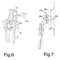
Figures 6 and 7 are a perspective view and a longitudinal sectional view, respectively, showing an alternative fastening mode of the guide ofFigure 3 to the inner panel of a door. - The window lifter according to the present invention comprises at least one guide adapted to be fastened to the inner panel of a motor vehicle door and provided with a slider configured to receive and support a window pane. The slider is slidably mounted on the guide.
- In the embodiment shown in
Figures 1 and2 , the window lifter 1 comprises in particular a pair ofguides inner panel 4 of a door D of a motor vehicle (not shown). Theguides slider window pane 7. - The window lifter 1 also comprises in known manner a drum 8 around which one or more moving cables (not shown) connected to the
sliders guide - The moving cables are supported on each
guide special sheaths - The
sliders Figures 1 and2 are shown in an higher stop position of therespective guides window pane 7 is completely extracted from aseat 12 formed within the door D of the motor vehicle. - As explained above, in the case of motor vehicles provided with frameless windows, the door D of the motor vehicle is completely devoid of a frame adapted to surround the window pane when this is completely extracted from its
seat 12, whereby in order to ensure adequate sealing conditions with respect to the ingress of air, dust and water into the passenger compartment it is necessary to create a certain compression level of thewindow pane 7 against the gaskets bordering the motor vehicle passenger compartment. - As shown in
Figure 2 , theupper edge 7a of thewindow pane 7 rests against thegaskets window pane 7 in which it exerts a minimum pressure against thegaskets window pane 7 is rotated as shown by the arrow F towards the passenger compartment of the motor vehicle so as to compress theseals - As known, the rotation of the
window pane 7 is obtained during assembly by modifying the inclination of the guides, 2, 3, of the window lifter 1 with respect to theinner panel 4 of the door D of the motor vehicle. This is obtained in particular by pivotally connecting one end of theguides inner panel 4 of the door D and by varying the distance between the opposite end of each guide and theinner panel 4 by suitable adjusting means, for example, screw registers. - According to the present invention, the window lifter 1 comprises a flexible member associated to one end of its at least one guide and configured to allow to fasten it to the
inner panel 4 of the door. Thanks to the use of a flexible member it is possible to obtain a rotation of thewindow pane 7 without resorting to a traditional hinge as in the case of the window lifters known in the field, but exploiting the deformation of the flexible member in the elastic range. This solution allows to simplify the traditional pivot connection of the guides of a window lifter on the inner panel of the door from a mechanical point of view, as well as to reduce the manufacturing costs of the guides and their assembly times. - According to a preferred embodiment, the flexible member is integrally formed in at least one guide of the window lifter.
- Referring now to
Figure 3 , which shows for simplicity only a guide of the window lifter 1, for example theguide 2, theflexible member 15 is in the form of a flap. Theflap 15 is integrally formed in theguide 2 at one end thereof by forming a through opening, for example a U-shaped through opening, around ahole 2a, which allows to fasten it to theinner panel 4 of the door D. This solution is particularly advantageous since it allows to carry out the invention e.g. by modifying a standard guide, and in any case without resorting to additional elements or to deep changes to the design of the fastening members of the guide. - Depending on design requirements, the
flexible member 15 may be suitably stiffened by way of one or more ribs oriented along the bending direction. - Referring again to
Figure 2 , theflexible member 15 is preferably associated to the upper end of eachguide slit 16 allowing thewindow pane 7 to come out from itsseat 12 within the door D. It will be understood that theflexible member 15 may also be associated to the opposite end of eachguide window pane 7 for adjusting the level of compression on the gaskets. However, the positioning of the flexible member at the upper ends of theguides exit slit 16 of thewindow pane 7 from theseat 12 results in a smaller deformation of thegaskets slit 16 and therefore allows to maintain an adequate level of tightness with respect to air, dust and water compatibly with the degree of rotation of thewindow pane 7 during the adjustment phase. - The assembly of the
guides inner panel 4 of the door at the end where theflexible member 15 is arranged, is generally carried out by means of a screw or a threaded pin. Considering the small thickness of the guides, it is preferable to use a holding member associated with theflexible member 15 and arranged coaxially to the fastening hole of the guide to theinner panel 4 of the door D. The holding member is provided with a threaded hole adapted to receive and hold the screw or threaded pin. - In the embodiment shown in
Figures 4 and 5 , the window lifter 1 comprises a holding member in the form of anut 19. Theguide 2 is fastened in known manner to theinner panel 4 of the door by means of a special threadedpin 20 that has a maneuveringcentral portion 20a having a cylindrical shape and two threadedposts pin 20 is arranged between theguide 2 and theinner panel 4 of the door D, while thenut 19 is welded on theflexible element 15 on the opposite side of theguide 2. A threaded post, for example thepost 20b, is inserted into the fastening hole of theguide 2, while theopposite post 20c is inserted into a corresponding hole formed in theinner panel 4 of the door D. Similarly to the threadedpost 20b, the threadedpost 20c can also be blocked on theinner panel 4 of the door D by a nut. - In the embodiment shown in
Figures 6 and 7 , the window lifter 1 comprises a holding member in the form of ametal block 21 provided with a threadedhole 21a adapted to receive and hold the threadedpin 20. Themetal block 21 is also provided with aslit 21b formed in the direction of its thickness, e.g. along a median plane thereof, and dimensioned so as to allow its fitting on the flap-shapedflexible member 15. Theslit 21b is dimensioned so that, once the metal block is fitted on theflexible element 15, the threadedhole 21a is coaxial with the fastening hole of theguide 2. This solution allows to further facilitate the assembly of theguide 2 on theinner panel 4 of the door D. In fact, once themetal block 21 is fitted on theflexible member 15, its position is blocked and the fastening holes are immediately aligned, whereby in order to assemble theguide 2, it is sufficient to rotate thecentral portion 20a of the threadedpin 20 without having to manually align the other components. - It is clear that the embodiment of the invention herein described and illustrated is only an example susceptible of numerous variants. For example, the
flexible member 15 might be integrally formed with theguide inner panel 4 of the door D away from the guide. This solution may be advantageous in case of interference problems among the mechanical components mounted on the guide, such as the pulleys and/or sliding blocks that guide the moving cables of the slider, and those mounted or to be mounted on theinner panel 4 of the door D proximate to the fastening points of theguides - Furthermore, the
flexible member 15 might be a component completely separate from theguides guide inner panel 4 of the door D. This solution may be advantageous when, due to design needs, it is necessary to use different materials for the manufacture of theflexible member 15 and/or use particular shapes that are cannot be easily obtained by starting from the basic structure of theguide
Claims (10)
- A window lifter (1) comprising at least one guide (2, 3) suitable to be fastened to an inner panel (4) of a door (D) of a motor vehicle, wherein said at least one guide (2, 3) is suitable to slidably support a slider (5, 6) so configured to receive and move a window pane (7), said window lifter (1) further comprising a flexible member (15) associated with the at least one guide (2, 3) at one end thereof, said flexible member (15) being a fastening member of the guide (2, 3) to the inner panel (4) of a door (D) of a motor vehicle, characterized in that said flexible member (15) is integrally formed in the guide (2, 3).
- A window lifter (1) according to the claim 1, wherein said flexible member (15) is a flap obtained by forming a through opening in the guide (2, 3) around a hole (2a) allowing to assemble it to the inner panel (4) of the door (D).
- A window lifter (1) according to claim 1, wherein said flexible member (15) is a flap outwardly protruding from an end of the guide (2, 3).
- A window lifter (1) according to any one of claims 1 to 3, wherein said flexible member (15) comprises one or a number of ribs oriented in a bending direction thereof.
- A window lifter (1) according to any one of claims 1 to 4, further comprising adjustment means arranged at the end of the guide (2, 3) opposite to the end at which the flexible member (15) is arranged, said adjustment means being suitable to adjust the distance between the guide (2, 3) and the inner panel (4) of the door (D).
- A window lifter (1) according to claim 5, wherein said adjustment means comprise a screw register.
- A window lifter (1) according to any one of previous claims 1 to 6, wherein the flexible member (15) is associated with the end of the guide (2, 3) intended to be arranged proximate to a slit (16) allowing the window pane (7) to come out from a seat (12) formed inside the door (D) of the motor vehicle.
- A window lifter (1) according to any one of claims 1 to 7, further comprising a holding member (19; 21) so configured to receive a threaded pin (20) suitable to allow to assemble the guide (2, 3) to the inner panel (4) of the door (D), said holding member (19; 21) being suitable to be restrained to the flexible member (15) coaxially to the assembling hole (2a) of the guide (2, 3) and being provided with a threaded hole (19a; 21a) suitable to receive and hold said threaded pin (20).
- A window lifter (1) according to claim 8, wherein said holding member is a nut (19).
- A window lifter (1) according to claim 8, wherein said holding member is a metal block (21), said metal block (21) being provided with a slit (21b) formed in the direction of its thickness and sized so as to allow to insert the block (21) into the flexible member (15) and such that, once the block (21) is inserted in the flexible member (15), said threaded hole (21a) is aligned with the assembling hole (2a) of the guide (2).
Applications Claiming Priority (1)
| Application Number | Priority Date | Filing Date | Title |
|---|---|---|---|
| IT000699A ITMI20110699A1 (en) | 2011-04-27 | 2011-04-27 | WINDOW |
Publications (2)
| Publication Number | Publication Date |
|---|---|
| EP2517910A1 EP2517910A1 (en) | 2012-10-31 |
| EP2517910B1 true EP2517910B1 (en) | 2014-05-21 |
Family
ID=44514889
Family Applications (1)
| Application Number | Title | Priority Date | Filing Date |
|---|---|---|---|
| EP12166021.1A Revoked EP2517910B1 (en) | 2011-04-27 | 2012-04-27 | Vehicle window lifter |
Country Status (2)
| Country | Link |
|---|---|
| EP (1) | EP2517910B1 (en) |
| IT (1) | ITMI20110699A1 (en) |
Families Citing this family (1)
| Publication number | Priority date | Publication date | Assignee | Title |
|---|---|---|---|---|
| DE102024208658A1 (en) * | 2024-09-11 | 2026-03-12 | Brose Fahrzeugteile Se & Co. Kommanditgesellschaft, Bamberg | Door assembly and door module of a frame door of a motor vehicle |
Family Cites Families (4)
| Publication number | Priority date | Publication date | Assignee | Title |
|---|---|---|---|---|
| US5855095A (en) * | 1997-05-06 | 1999-01-05 | General Motors Corporation | Boltless glass channel attachment |
| DE19734995B4 (en) * | 1997-08-13 | 2004-03-25 | Kiekert Ag | Device for fastening a window pane, in particular the window pane of a motor vehicle door, to a pane carrier |
| DE20302066U1 (en) * | 2003-02-06 | 2004-03-18 | Brose Fahrzeugteile Gmbh & Co. Kommanditgesellschaft, Coburg | Window lifter for motor vehicle door uses cable with multiple fastenings for attachment to door using elastomeric insert between them |
| DE102005024490A1 (en) * | 2005-05-27 | 2006-12-07 | Daimlerchrysler Ag | Motor vehicle door, has adjustable connecting system for operation of basic automotive body that is linked with side of vehicle to effect properly matched, close arrangement of windowpane at edge of door opening in closed position of body |
-
2011
- 2011-04-27 IT IT000699A patent/ITMI20110699A1/en unknown
-
2012
- 2012-04-27 EP EP12166021.1A patent/EP2517910B1/en not_active Revoked
Also Published As
| Publication number | Publication date |
|---|---|
| ITMI20110699A1 (en) | 2012-10-28 |
| EP2517910A1 (en) | 2012-10-31 |
Similar Documents
| Publication | Publication Date | Title |
|---|---|---|
| EP2399796B1 (en) | Railway platform door device | |
| CN108474230B (en) | Opening and closing mechanism for opening and closing body | |
| US4805346A (en) | Vehicle door glass attachment to cable drive window regulator mechanism | |
| US10287814B2 (en) | Pulley rivet for installation of pulleys for window regulator systems | |
| US9387748B2 (en) | Roll shade apparatus for vehicle | |
| US20120260577A1 (en) | Linear actuator particularly for sliding doors and for sliding door or window closure elements in general | |
| KR20010033151A (en) | Door module | |
| CN102733747A (en) | Roller blind device for a motor vehicle | |
| US20180328096A1 (en) | Window regulator | |
| KR101209499B1 (en) | Unit support for a motor vehicle door | |
| US20200291711A1 (en) | Rail adjuster system and method for window regulator systems | |
| EP2517910A1 (en) | Vehicle window lifter | |
| US9771746B2 (en) | Window regulator for a door assembly of a vehicle | |
| US20170314308A1 (en) | Window Lifter | |
| US20110120020A1 (en) | Device for closing off a window made in a motor vehicle, corresponding roof and corresponding vehicle | |
| KR102452579B1 (en) | Windows regulator for vehicle | |
| KR100774329B1 (en) | Sunroof decoration cover assembly | |
| US7062880B2 (en) | Stabilizer clip for window assembly | |
| KR102173001B1 (en) | Wire clip for windows regulator and windows regulator | |
| US20020162280A1 (en) | Profiled belt-type regulator | |
| JP2011174337A (en) | Mounting structure of window regulator device | |
| US20070296245A1 (en) | Sliding Door For A Motor Vehicle | |
| EP0943774A2 (en) | Actuator with adjustable stroke | |
| KR20180032344A (en) | Guide rail apparatus for Auto door | |
| KR20160111088A (en) | Interlocking device for sliding windows and doors |
Legal Events
| Date | Code | Title | Description |
|---|---|---|---|
| PUAI | Public reference made under article 153(3) epc to a published international application that has entered the european phase |
Free format text: ORIGINAL CODE: 0009012 |
|
| AK | Designated contracting states |
Kind code of ref document: A1 Designated state(s): AL AT BE BG CH CY CZ DE DK EE ES FI FR GB GR HR HU IE IS IT LI LT LU LV MC MK MT NL NO PL PT RO RS SE SI SK SM TR |
|
| AX | Request for extension of the european patent |
Extension state: BA ME |
|
| 17P | Request for examination filed |
Effective date: 20130430 |
|
| GRAP | Despatch of communication of intention to grant a patent |
Free format text: ORIGINAL CODE: EPIDOSNIGR1 |
|
| INTG | Intention to grant announced |
Effective date: 20140109 |
|
| GRAS | Grant fee paid |
Free format text: ORIGINAL CODE: EPIDOSNIGR3 |
|
| GRAA | (expected) grant |
Free format text: ORIGINAL CODE: 0009210 |
|
| AK | Designated contracting states |
Kind code of ref document: B1 Designated state(s): AL AT BE BG CH CY CZ DE DK EE ES FI FR GB GR HR HU IE IS IT LI LT LU LV MC MK MT NL NO PL PT RO RS SE SI SK SM TR |
|
| REG | Reference to a national code |
Ref country code: GB Ref legal event code: FG4D |
|
| REG | Reference to a national code |
Ref country code: CH Ref legal event code: EP |
|
| REG | Reference to a national code |
Ref country code: AT Ref legal event code: REF Ref document number: 669411 Country of ref document: AT Kind code of ref document: T Effective date: 20140615 |
|
| REG | Reference to a national code |
Ref country code: IE Ref legal event code: FG4D |
|
| REG | Reference to a national code |
Ref country code: DE Ref legal event code: R096 Ref document number: 602012001861 Country of ref document: DE Effective date: 20140710 |
|
| REG | Reference to a national code |
Ref country code: AT Ref legal event code: MK05 Ref document number: 669411 Country of ref document: AT Kind code of ref document: T Effective date: 20140521 Ref country code: NL Ref legal event code: VDEP Effective date: 20140521 |
|
| REG | Reference to a national code |
Ref country code: LT Ref legal event code: MG4D |
|
| PG25 | Lapsed in a contracting state [announced via postgrant information from national office to epo] |
Ref country code: NO Free format text: LAPSE BECAUSE OF FAILURE TO SUBMIT A TRANSLATION OF THE DESCRIPTION OR TO PAY THE FEE WITHIN THE PRESCRIBED TIME-LIMIT Effective date: 20140821 Ref country code: LT Free format text: LAPSE BECAUSE OF FAILURE TO SUBMIT A TRANSLATION OF THE DESCRIPTION OR TO PAY THE FEE WITHIN THE PRESCRIBED TIME-LIMIT Effective date: 20140521 Ref country code: IS Free format text: LAPSE BECAUSE OF FAILURE TO SUBMIT A TRANSLATION OF THE DESCRIPTION OR TO PAY THE FEE WITHIN THE PRESCRIBED TIME-LIMIT Effective date: 20140921 Ref country code: GR Free format text: LAPSE BECAUSE OF FAILURE TO SUBMIT A TRANSLATION OF THE DESCRIPTION OR TO PAY THE FEE WITHIN THE PRESCRIBED TIME-LIMIT Effective date: 20140822 Ref country code: FI Free format text: LAPSE BECAUSE OF FAILURE TO SUBMIT A TRANSLATION OF THE DESCRIPTION OR TO PAY THE FEE WITHIN THE PRESCRIBED TIME-LIMIT Effective date: 20140521 |
|
| PG25 | Lapsed in a contracting state [announced via postgrant information from national office to epo] |
Ref country code: PL Free format text: LAPSE BECAUSE OF FAILURE TO SUBMIT A TRANSLATION OF THE DESCRIPTION OR TO PAY THE FEE WITHIN THE PRESCRIBED TIME-LIMIT Effective date: 20140521 Ref country code: AT Free format text: LAPSE BECAUSE OF FAILURE TO SUBMIT A TRANSLATION OF THE DESCRIPTION OR TO PAY THE FEE WITHIN THE PRESCRIBED TIME-LIMIT Effective date: 20140521 Ref country code: LV Free format text: LAPSE BECAUSE OF FAILURE TO SUBMIT A TRANSLATION OF THE DESCRIPTION OR TO PAY THE FEE WITHIN THE PRESCRIBED TIME-LIMIT Effective date: 20140521 Ref country code: HR Free format text: LAPSE BECAUSE OF FAILURE TO SUBMIT A TRANSLATION OF THE DESCRIPTION OR TO PAY THE FEE WITHIN THE PRESCRIBED TIME-LIMIT Effective date: 20140521 Ref country code: ES Free format text: LAPSE BECAUSE OF FAILURE TO SUBMIT A TRANSLATION OF THE DESCRIPTION OR TO PAY THE FEE WITHIN THE PRESCRIBED TIME-LIMIT Effective date: 20140521 Ref country code: SE Free format text: LAPSE BECAUSE OF FAILURE TO SUBMIT A TRANSLATION OF THE DESCRIPTION OR TO PAY THE FEE WITHIN THE PRESCRIBED TIME-LIMIT Effective date: 20140521 Ref country code: RS Free format text: LAPSE BECAUSE OF FAILURE TO SUBMIT A TRANSLATION OF THE DESCRIPTION OR TO PAY THE FEE WITHIN THE PRESCRIBED TIME-LIMIT Effective date: 20140521 |
|
| PG25 | Lapsed in a contracting state [announced via postgrant information from national office to epo] |
Ref country code: PT Free format text: LAPSE BECAUSE OF FAILURE TO SUBMIT A TRANSLATION OF THE DESCRIPTION OR TO PAY THE FEE WITHIN THE PRESCRIBED TIME-LIMIT Effective date: 20140922 |
|
| REG | Reference to a national code |
Ref country code: DE Ref legal event code: R026 Ref document number: 602012001861 Country of ref document: DE |
|
| PLBI | Opposition filed |
Free format text: ORIGINAL CODE: 0009260 |
|
| PG25 | Lapsed in a contracting state [announced via postgrant information from national office to epo] |
Ref country code: RO Free format text: LAPSE BECAUSE OF FAILURE TO SUBMIT A TRANSLATION OF THE DESCRIPTION OR TO PAY THE FEE WITHIN THE PRESCRIBED TIME-LIMIT Effective date: 20140521 Ref country code: EE Free format text: LAPSE BECAUSE OF FAILURE TO SUBMIT A TRANSLATION OF THE DESCRIPTION OR TO PAY THE FEE WITHIN THE PRESCRIBED TIME-LIMIT Effective date: 20140521 Ref country code: BE Free format text: LAPSE BECAUSE OF FAILURE TO SUBMIT A TRANSLATION OF THE DESCRIPTION OR TO PAY THE FEE WITHIN THE PRESCRIBED TIME-LIMIT Effective date: 20140521 Ref country code: DK Free format text: LAPSE BECAUSE OF FAILURE TO SUBMIT A TRANSLATION OF THE DESCRIPTION OR TO PAY THE FEE WITHIN THE PRESCRIBED TIME-LIMIT Effective date: 20140521 Ref country code: SK Free format text: LAPSE BECAUSE OF FAILURE TO SUBMIT A TRANSLATION OF THE DESCRIPTION OR TO PAY THE FEE WITHIN THE PRESCRIBED TIME-LIMIT Effective date: 20140521 Ref country code: CZ Free format text: LAPSE BECAUSE OF FAILURE TO SUBMIT A TRANSLATION OF THE DESCRIPTION OR TO PAY THE FEE WITHIN THE PRESCRIBED TIME-LIMIT Effective date: 20140521 |
|
| 26 | Opposition filed |
Opponent name: BROSE FAHRZEUGTEILE GMBH & CO. KG, COBURG Effective date: 20150120 |
|
| PG25 | Lapsed in a contracting state [announced via postgrant information from national office to epo] |
Ref country code: NL Free format text: LAPSE BECAUSE OF FAILURE TO SUBMIT A TRANSLATION OF THE DESCRIPTION OR TO PAY THE FEE WITHIN THE PRESCRIBED TIME-LIMIT Effective date: 20140521 |
|
| PLAX | Notice of opposition and request to file observation + time limit sent |
Free format text: ORIGINAL CODE: EPIDOSNOBS2 |
|
| REG | Reference to a national code |
Ref country code: DE Ref legal event code: R026 Ref document number: 602012001861 Country of ref document: DE Effective date: 20150120 |
|
| PLAF | Information modified related to communication of a notice of opposition and request to file observations + time limit |
Free format text: ORIGINAL CODE: EPIDOSCOBS2 |
|
| PG25 | Lapsed in a contracting state [announced via postgrant information from national office to epo] |
Ref country code: SI Free format text: LAPSE BECAUSE OF FAILURE TO SUBMIT A TRANSLATION OF THE DESCRIPTION OR TO PAY THE FEE WITHIN THE PRESCRIBED TIME-LIMIT Effective date: 20140521 |
|
| PLAB | Opposition data, opponent's data or that of the opponent's representative modified |
Free format text: ORIGINAL CODE: 0009299OPPO |
|
| R26 | Opposition filed (corrected) |
Opponent name: BROSE FAHRZEUGTEILE GMBH & CO. KG, COBURG Effective date: 20150120 |
|
| PG25 | Lapsed in a contracting state [announced via postgrant information from national office to epo] |
Ref country code: MC Free format text: LAPSE BECAUSE OF FAILURE TO SUBMIT A TRANSLATION OF THE DESCRIPTION OR TO PAY THE FEE WITHIN THE PRESCRIBED TIME-LIMIT Effective date: 20140521 Ref country code: LU Free format text: LAPSE BECAUSE OF FAILURE TO SUBMIT A TRANSLATION OF THE DESCRIPTION OR TO PAY THE FEE WITHIN THE PRESCRIBED TIME-LIMIT Effective date: 20150427 |
|
| REG | Reference to a national code |
Ref country code: CH Ref legal event code: PL |
|
| REG | Reference to a national code |
Ref country code: IE Ref legal event code: MM4A |
|
| PG25 | Lapsed in a contracting state [announced via postgrant information from national office to epo] |
Ref country code: LI Free format text: LAPSE BECAUSE OF NON-PAYMENT OF DUE FEES Effective date: 20150430 Ref country code: CH Free format text: LAPSE BECAUSE OF NON-PAYMENT OF DUE FEES Effective date: 20150430 |
|
| PG25 | Lapsed in a contracting state [announced via postgrant information from national office to epo] |
Ref country code: IE Free format text: LAPSE BECAUSE OF NON-PAYMENT OF DUE FEES Effective date: 20150427 |
|
| REG | Reference to a national code |
Ref country code: FR Ref legal event code: PLFP Year of fee payment: 5 |
|
| RDAF | Communication despatched that patent is revoked |
Free format text: ORIGINAL CODE: EPIDOSNREV1 |
|
| REG | Reference to a national code |
Ref country code: DE Ref legal event code: R103 Ref document number: 602012001861 Country of ref document: DE Ref country code: DE Ref legal event code: R064 Ref document number: 602012001861 Country of ref document: DE |
|
| PGFP | Annual fee paid to national office [announced via postgrant information from national office to epo] |
Ref country code: DE Payment date: 20160429 Year of fee payment: 5 Ref country code: GB Payment date: 20160429 Year of fee payment: 5 |
|
| PGFP | Annual fee paid to national office [announced via postgrant information from national office to epo] |
Ref country code: FR Payment date: 20160429 Year of fee payment: 5 Ref country code: IT Payment date: 20160405 Year of fee payment: 5 |
|
| RDAG | Patent revoked |
Free format text: ORIGINAL CODE: 0009271 |
|
| STAA | Information on the status of an ep patent application or granted ep patent |
Free format text: STATUS: PATENT REVOKED |
|
| 27W | Patent revoked |
Effective date: 20160721 |
|
| GBPR | Gb: patent revoked under art. 102 of the ep convention designating the uk as contracting state |
Effective date: 20160721 |
|
| PG25 | Lapsed in a contracting state [announced via postgrant information from national office to epo] |
Ref country code: MT Free format text: LAPSE BECAUSE OF FAILURE TO SUBMIT A TRANSLATION OF THE DESCRIPTION OR TO PAY THE FEE WITHIN THE PRESCRIBED TIME-LIMIT Effective date: 20140521 |
|
| PG25 | Lapsed in a contracting state [announced via postgrant information from national office to epo] |
Ref country code: HU Free format text: LAPSE BECAUSE OF FAILURE TO SUBMIT A TRANSLATION OF THE DESCRIPTION OR TO PAY THE FEE WITHIN THE PRESCRIBED TIME-LIMIT; INVALID AB INITIO Effective date: 20120427 |
|
| PG25 | Lapsed in a contracting state [announced via postgrant information from national office to epo] |
Ref country code: AL Free format text: LAPSE BECAUSE OF FAILURE TO SUBMIT A TRANSLATION OF THE DESCRIPTION OR TO PAY THE FEE WITHIN THE PRESCRIBED TIME-LIMIT Effective date: 20140521 |
|
| PG25 | Lapsed in a contracting state [announced via postgrant information from national office to epo] |
Ref country code: BG Free format text: LAPSE BECAUSE OF FAILURE TO SUBMIT A TRANSLATION OF THE DESCRIPTION OR TO PAY THE FEE WITHIN THE PRESCRIBED TIME-LIMIT Effective date: 20140521 |
|
| PG25 | Lapsed in a contracting state [announced via postgrant information from national office to epo] |
Ref country code: CY Free format text: LAPSE BECAUSE OF FAILURE TO SUBMIT A TRANSLATION OF THE DESCRIPTION OR TO PAY THE FEE WITHIN THE PRESCRIBED TIME-LIMIT Effective date: 20140521 |
|
| PG25 | Lapsed in a contracting state [announced via postgrant information from national office to epo] |
Ref country code: TR Free format text: LAPSE BECAUSE OF FAILURE TO SUBMIT A TRANSLATION OF THE DESCRIPTION OR TO PAY THE FEE WITHIN THE PRESCRIBED TIME-LIMIT Effective date: 20140521 |