EP2517854A1 - Impregnation section with upstream surface and method for impregnation fiber rovings - Google Patents
Impregnation section with upstream surface and method for impregnation fiber rovings Download PDFInfo
- Publication number
- EP2517854A1 EP2517854A1 EP12166161A EP12166161A EP2517854A1 EP 2517854 A1 EP2517854 A1 EP 2517854A1 EP 12166161 A EP12166161 A EP 12166161A EP 12166161 A EP12166161 A EP 12166161A EP 2517854 A1 EP2517854 A1 EP 2517854A1
- Authority
- EP
- European Patent Office
- Prior art keywords
- resin
- impregnation
- roving
- rovings
- zone
- Prior art date
- Legal status (The legal status is an assumption and is not a legal conclusion. Google has not performed a legal analysis and makes no representation as to the accuracy of the status listed.)
- Granted
Links
Images







Classifications
-
- B—PERFORMING OPERATIONS; TRANSPORTING
- B29—WORKING OF PLASTICS; WORKING OF SUBSTANCES IN A PLASTIC STATE IN GENERAL
- B29B—PREPARATION OR PRETREATMENT OF THE MATERIAL TO BE SHAPED; MAKING GRANULES OR PREFORMS; RECOVERY OF PLASTICS OR OTHER CONSTITUENTS OF WASTE MATERIAL CONTAINING PLASTICS
- B29B15/00—Pretreatment of the material to be shaped, not covered by groups B29B7/00 - B29B13/00
- B29B15/08—Pretreatment of the material to be shaped, not covered by groups B29B7/00 - B29B13/00 of reinforcements or fillers
- B29B15/10—Coating or impregnating independently of the moulding or shaping step
- B29B15/12—Coating or impregnating independently of the moulding or shaping step of reinforcements of indefinite length
- B29B15/122—Coating or impregnating independently of the moulding or shaping step of reinforcements of indefinite length with a matrix in liquid form, e.g. as melt, solution or latex
-
- B—PERFORMING OPERATIONS; TRANSPORTING
- B29—WORKING OF PLASTICS; WORKING OF SUBSTANCES IN A PLASTIC STATE IN GENERAL
- B29B—PREPARATION OR PRETREATMENT OF THE MATERIAL TO BE SHAPED; MAKING GRANULES OR PREFORMS; RECOVERY OF PLASTICS OR OTHER CONSTITUENTS OF WASTE MATERIAL CONTAINING PLASTICS
- B29B15/00—Pretreatment of the material to be shaped, not covered by groups B29B7/00 - B29B13/00
- B29B15/08—Pretreatment of the material to be shaped, not covered by groups B29B7/00 - B29B13/00 of reinforcements or fillers
- B29B15/10—Coating or impregnating independently of the moulding or shaping step
-
- B—PERFORMING OPERATIONS; TRANSPORTING
- B29—WORKING OF PLASTICS; WORKING OF SUBSTANCES IN A PLASTIC STATE IN GENERAL
- B29C—SHAPING OR JOINING OF PLASTICS; SHAPING OF MATERIAL IN A PLASTIC STATE, NOT OTHERWISE PROVIDED FOR; AFTER-TREATMENT OF THE SHAPED PRODUCTS, e.g. REPAIRING
- B29C48/00—Extrusion moulding, i.e. expressing the moulding material through a die or nozzle which imparts the desired form; Apparatus therefor
- B29C48/03—Extrusion moulding, i.e. expressing the moulding material through a die or nozzle which imparts the desired form; Apparatus therefor characterised by the shape of the extruded material at extrusion
- B29C48/05—Filamentary, e.g. strands
-
- B—PERFORMING OPERATIONS; TRANSPORTING
- B29—WORKING OF PLASTICS; WORKING OF SUBSTANCES IN A PLASTIC STATE IN GENERAL
- B29C—SHAPING OR JOINING OF PLASTICS; SHAPING OF MATERIAL IN A PLASTIC STATE, NOT OTHERWISE PROVIDED FOR; AFTER-TREATMENT OF THE SHAPED PRODUCTS, e.g. REPAIRING
- B29C48/00—Extrusion moulding, i.e. expressing the moulding material through a die or nozzle which imparts the desired form; Apparatus therefor
- B29C48/03—Extrusion moulding, i.e. expressing the moulding material through a die or nozzle which imparts the desired form; Apparatus therefor characterised by the shape of the extruded material at extrusion
- B29C48/07—Flat, e.g. panels
- B29C48/08—Flat, e.g. panels flexible, e.g. films
-
- B—PERFORMING OPERATIONS; TRANSPORTING
- B29—WORKING OF PLASTICS; WORKING OF SUBSTANCES IN A PLASTIC STATE IN GENERAL
- B29C—SHAPING OR JOINING OF PLASTICS; SHAPING OF MATERIAL IN A PLASTIC STATE, NOT OTHERWISE PROVIDED FOR; AFTER-TREATMENT OF THE SHAPED PRODUCTS, e.g. REPAIRING
- B29C48/00—Extrusion moulding, i.e. expressing the moulding material through a die or nozzle which imparts the desired form; Apparatus therefor
- B29C48/15—Extrusion moulding, i.e. expressing the moulding material through a die or nozzle which imparts the desired form; Apparatus therefor incorporating preformed parts or layers, e.g. extrusion moulding around inserts
- B29C48/156—Coating two or more articles simultaneously
-
- B—PERFORMING OPERATIONS; TRANSPORTING
- B29—WORKING OF PLASTICS; WORKING OF SUBSTANCES IN A PLASTIC STATE IN GENERAL
- B29C—SHAPING OR JOINING OF PLASTICS; SHAPING OF MATERIAL IN A PLASTIC STATE, NOT OTHERWISE PROVIDED FOR; AFTER-TREATMENT OF THE SHAPED PRODUCTS, e.g. REPAIRING
- B29C48/00—Extrusion moulding, i.e. expressing the moulding material through a die or nozzle which imparts the desired form; Apparatus therefor
- B29C48/25—Component parts, details or accessories; Auxiliary operations
- B29C48/30—Extrusion nozzles or dies
- B29C48/305—Extrusion nozzles or dies having a wide opening, e.g. for forming sheets
-
- B—PERFORMING OPERATIONS; TRANSPORTING
- B29—WORKING OF PLASTICS; WORKING OF SUBSTANCES IN A PLASTIC STATE IN GENERAL
- B29C—SHAPING OR JOINING OF PLASTICS; SHAPING OF MATERIAL IN A PLASTIC STATE, NOT OTHERWISE PROVIDED FOR; AFTER-TREATMENT OF THE SHAPED PRODUCTS, e.g. REPAIRING
- B29C48/00—Extrusion moulding, i.e. expressing the moulding material through a die or nozzle which imparts the desired form; Apparatus therefor
- B29C48/001—Combinations of extrusion moulding with other shaping operations
- B29C48/0011—Combinations of extrusion moulding with other shaping operations combined with compression moulding
-
- B—PERFORMING OPERATIONS; TRANSPORTING
- B29—WORKING OF PLASTICS; WORKING OF SUBSTANCES IN A PLASTIC STATE IN GENERAL
- B29C—SHAPING OR JOINING OF PLASTICS; SHAPING OF MATERIAL IN A PLASTIC STATE, NOT OTHERWISE PROVIDED FOR; AFTER-TREATMENT OF THE SHAPED PRODUCTS, e.g. REPAIRING
- B29C48/00—Extrusion moulding, i.e. expressing the moulding material through a die or nozzle which imparts the desired form; Apparatus therefor
- B29C48/03—Extrusion moulding, i.e. expressing the moulding material through a die or nozzle which imparts the desired form; Apparatus therefor characterised by the shape of the extruded material at extrusion
- B29C48/12—Articles with an irregular circumference when viewed in cross-section, e.g. window profiles
-
- B—PERFORMING OPERATIONS; TRANSPORTING
- B29—WORKING OF PLASTICS; WORKING OF SUBSTANCES IN A PLASTIC STATE IN GENERAL
- B29C—SHAPING OR JOINING OF PLASTICS; SHAPING OF MATERIAL IN A PLASTIC STATE, NOT OTHERWISE PROVIDED FOR; AFTER-TREATMENT OF THE SHAPED PRODUCTS, e.g. REPAIRING
- B29C48/00—Extrusion moulding, i.e. expressing the moulding material through a die or nozzle which imparts the desired form; Apparatus therefor
- B29C48/25—Component parts, details or accessories; Auxiliary operations
- B29C48/28—Storing of extruded material, e.g. by winding up or stacking
-
- B—PERFORMING OPERATIONS; TRANSPORTING
- B29—WORKING OF PLASTICS; WORKING OF SUBSTANCES IN A PLASTIC STATE IN GENERAL
- B29C—SHAPING OR JOINING OF PLASTICS; SHAPING OF MATERIAL IN A PLASTIC STATE, NOT OTHERWISE PROVIDED FOR; AFTER-TREATMENT OF THE SHAPED PRODUCTS, e.g. REPAIRING
- B29C48/00—Extrusion moulding, i.e. expressing the moulding material through a die or nozzle which imparts the desired form; Apparatus therefor
- B29C48/25—Component parts, details or accessories; Auxiliary operations
- B29C48/30—Extrusion nozzles or dies
- B29C48/32—Extrusion nozzles or dies with annular openings, e.g. for forming tubular articles
- B29C48/34—Cross-head annular extrusion nozzles, i.e. for simultaneously receiving moulding material and the preform to be coated
-
- B—PERFORMING OPERATIONS; TRANSPORTING
- B29—WORKING OF PLASTICS; WORKING OF SUBSTANCES IN A PLASTIC STATE IN GENERAL
- B29C—SHAPING OR JOINING OF PLASTICS; SHAPING OF MATERIAL IN A PLASTIC STATE, NOT OTHERWISE PROVIDED FOR; AFTER-TREATMENT OF THE SHAPED PRODUCTS, e.g. REPAIRING
- B29C48/00—Extrusion moulding, i.e. expressing the moulding material through a die or nozzle which imparts the desired form; Apparatus therefor
- B29C48/25—Component parts, details or accessories; Auxiliary operations
- B29C48/36—Means for plasticising or homogenising the moulding material or forcing it through the nozzle or die
- B29C48/50—Details of extruders
- B29C48/695—Flow dividers, e.g. breaker plates
-
- B—PERFORMING OPERATIONS; TRANSPORTING
- B29—WORKING OF PLASTICS; WORKING OF SUBSTANCES IN A PLASTIC STATE IN GENERAL
- B29C—SHAPING OR JOINING OF PLASTICS; SHAPING OF MATERIAL IN A PLASTIC STATE, NOT OTHERWISE PROVIDED FOR; AFTER-TREATMENT OF THE SHAPED PRODUCTS, e.g. REPAIRING
- B29C48/00—Extrusion moulding, i.e. expressing the moulding material through a die or nozzle which imparts the desired form; Apparatus therefor
- B29C48/25—Component parts, details or accessories; Auxiliary operations
- B29C48/36—Means for plasticising or homogenising the moulding material or forcing it through the nozzle or die
- B29C48/50—Details of extruders
- B29C48/695—Flow dividers, e.g. breaker plates
- B29C48/70—Flow dividers, e.g. breaker plates comprising means for dividing, distributing and recombining melt flows
- B29C48/705—Flow dividers, e.g. breaker plates comprising means for dividing, distributing and recombining melt flows in the die zone, e.g. to create flow homogeneity
-
- B—PERFORMING OPERATIONS; TRANSPORTING
- B29—WORKING OF PLASTICS; WORKING OF SUBSTANCES IN A PLASTIC STATE IN GENERAL
- B29C—SHAPING OR JOINING OF PLASTICS; SHAPING OF MATERIAL IN A PLASTIC STATE, NOT OTHERWISE PROVIDED FOR; AFTER-TREATMENT OF THE SHAPED PRODUCTS, e.g. REPAIRING
- B29C48/00—Extrusion moulding, i.e. expressing the moulding material through a die or nozzle which imparts the desired form; Apparatus therefor
- B29C48/25—Component parts, details or accessories; Auxiliary operations
- B29C48/78—Thermal treatment of the extrusion moulding material or of preformed parts or layers, e.g. by heating or cooling
- B29C48/80—Thermal treatment of the extrusion moulding material or of preformed parts or layers, e.g. by heating or cooling at the plasticising zone, e.g. by heating cylinders
- B29C48/83—Heating or cooling the cylinders
- B29C48/832—Heating
Definitions
- Fiber rovings have been employed in a wide variety of applications. For example, such rovings have been utilized to form fiber-reinforced composite rods.
- the rods may be utilized as lightweight structural reinforcements.
- power umbilicals are often used in the transmission of fluids and/or electric signals between the sea surface and equipment located on the sea bed. To help strengthen such umbilicals, attempts have been made to use pultruded carbon fiber rods as separate load carrying elements.
- Profiles are pultruded parts with a wide variety of cross-sectional shapes, and may be employed as a structural member for window lineals, decking planks, railings, balusters, roofing tiles, siding, trim boards, pipe, fencing, posts, light posts, highway signage, roadside marker posts, etc.
- Hollow profiles have been formed by pulling ("pultruding") continuous fiber rovings through a resin and then shaping the fiber-reinforced resin within a pultrusion die.
- fiber rovings may generally be utilized in any suitable applications to form, for example, suitable fiber reinforced plastics. As is generally known in the art, rovings utilized in these applications are typically combined with a polymer resin.
- thermoset resins e.g., vinyl esters
- Thermoset resins are difficult to use during manufacturing and do not possess good bonding characteristics for forming layers with other materials.
- attempts have been made to form rovings from thermoplastic polymers in other types of applications.
- U.S. Patent Publication No. 2005/0186410 to Bryant, et al. describes attempts that were made to embed carbon fibers into a thermoplastic resin to form a composite core of an electrical transmission cable.
- Bryant, et al. notes that these cores exhibited flaws and dry spots due to inadequate wetting of the fibers, which resulted in poor durability and strength.
- Another problem with such cores is that the thermoplastic resins could not operate at a high temperature.
- an impregnation section of a die for impregnating at least one fiber roving with a polymer resin.
- the impregnation section includes an impregnation zone configured to impregnate the roving with the resin, and a gate passage in fluid communication with the impregnation zone for flowing the resin therethrough such that the resin coats the roving.
- the impregnation section further includes a surface disposed upstream of the impregnation zone in a run direction of the roving for contacting the roving.
- a method for impregnating at least one fiber roving with a polymer resin.
- the method includes traversing at least one fiber roving over a surface, flowing a polymer resin through a gap, the gap being in the range between approximately 0.1 millimeters and approximately 4 millimeters, coating the roving with the resin, and traversing the coated roving through an impregnation zone to impregnate the roving with the resin.
- Fig. 1 is a schematic illustration of one embodiment of an impregnation system for use in the present invention
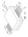
- Fig. 2 is a perspective view of one embodiment of a die for use in the present invention
- Fig. 3 is an opposing perspective view of one embodiment of a die for use in the present invention.
- Fig. 4 is a cross-sectional view of the die shown in Fig. 2 ;
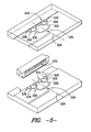
- Fig. 5 is an exploded view of one embodiment of a manifold assembly and gate passage for a die that may be employed in the present invention
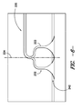
- Fig. 6 is a plan view of one embodiment of a manifold assembly that may be employed in the present invention.
- Fig. 7 is a plan view of another embodiment of a manifold assembly that may be employed in the present invention.
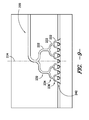
- Fig. 8 is a plan view of another embodiment of a manifold assembly that may be employed in the present invention.
- Fig. 9 is a plan view of another embodiment of a manifold assembly that may be employed in the present invention.
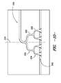
- Fig. 10 is a plan view of another embodiment of a manifold assembly that may be employed in the present invention.
- Fig. 11 is a plan view of another embodiment of a manifold assembly that may be employed in the present invention.
- Fig. 12 is a perspective view of one embodiment of a plate at least partially defining an impregnation zone that may be employed in the present invention
- Fig. 13 is a close-up cross-sectional view, as indicated in Fig. 4 , of one embodiment of a portion of an impregnation zone that may be employed in the present invention
- Fig. 14 is a close-up cross-sectional view of another embodiment of a portion of an impregnation zone that may be employed in the present invention.
- Fig. 15 is a close-up cross-sectional view of another embodiment of a portion of an impregnation zone that may be employed in the present invention.
- Fig. 16 is a close-up cross-sectional view of another embodiment of a portion of an impregnation zone that may be employed in the present invention.
- Fig. 17 is a close-up cross-sectional view of another embodiment of a portion of an impregnation zone that may be employed in the present invention.
- Fig. 18 is a perspective view of one embodiment of a land zone that may be employed in the present invention.
- Fig. 19 is a perspective view of another embodiment of a land zone that may be employed in the present invention.
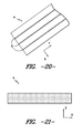
- Fig. 20 is a perspective view of one embodiment of a consolidated ribbon for use in the present invention.
- Fig. 21 is a cross-sectional view of the ribbon shown in Fig. 20 .
- the present invention is directed to an impregnation section for a die and a method for impregnating fiber rovings with a polymer resin.
- the impregnated fiber rovings may be utilized in composite rods, profiles, or any other suitable fiber reinforced plastic applications.
- the impregnation section generally includes an impregnation zone and a gate passage in fluid communication with the impregnation zone.
- the gate passage flows a polymer resin therethrough such that the resin coats a roving or rovings that are traversed through the die. After being coated with the resin, the rovings are traversed through the impregnation zone and impregnated therein with the resin.
- the impregnation section further includes a surface disposed upstream of the impregnation zone. As discussed below, the surface ensures that the rovings traversing through the die are generally consistently spaced apart when coated with the resin, and further locates the rovings desirably close to an outlet of the gate passage.
- an extrusion device may be employed in conjunction with the die to impregnate the rovings with the polymer.
- the extrusion device further facilitates the ability of the polymer to be applied to the entire surface of the fibers, as discussed below.
- the apparatus includes an extruder 120 containing a screw shaft 124 mounted inside a barrel 122.
- a heater 130 e.g., electrical resistance heater
- a polymer feedstock 127 is supplied to the extruder 120 through a hopper 126.
- the feedstock 127 is conveyed inside the barrel 122 by the screw shaft 124 and heated by frictional forces inside the barrel 122 and by the heater 130.
- the feedstock 127 exits the barrel 122 through a barrel flange 128 and enters a die flange 132 of an impregnation die 150.
- a continuous fiber roving 142 or a plurality of continuous fiber rovings 142 may be supplied from a reel or reels 144 to die 150.
- the rovings 142 may be spread apart before being supplied for impregnation, and may be supplied vertically, horizontally, or at any suitable angle. After being supplied, the rovings 142 may be generally positioned side-by-side, with minimal to no distance between neighboring rovings, before impregnation.
- the feedstock 127 may further be heated inside the die by heaters 133 mounted in or around the die 150.
- the die is generally operated at temperatures that are sufficient to cause and/or maintain the proper melt temperature for the polymer, thus allowing for the desired level of impregnation of the rovings by the polymer.
- the operation temperature of the die is higher than the melt temperature of the polymer, such as at temperatures from about 200°C to about 450°C.
- the continuous fiber rovings 142 become embedded in the polymer matrix, which may be a resin 214 ( Fig. 4 ) processed from the feedstock 127.
- the mixture may then exit the impregnation die 150 as wetted composite or extrudate 152.
- the term "roving" generally refers to a bundle of individual fibers.
- the fibers contained within the roving can be twisted or can be straight.
- the rovings may contain a single fiber type or different types of fibers. Different fibers may also be contained in individual rovings or, alternatively, each roving may contain a different fiber type.
- the continuous fibers employed in the rovings possess a high degree of tensile strength relative to their mass. For example, the ultimate tensile strength of the fibers is typically from about 1,000 to about 15,000 Megapascals ("MPa"), in some embodiments from about 2,000 MPa to about 10,000 MPa, and in some embodiments, from about 3,000 MPa to about 6,000 MPa.
- MPa Megapascals
- Such tensile strengths may be achieved even though the fibers are of a relatively light weight, such as a mass per unit length of from about 0.05 to about 2 grams per meter, in some embodiments from about 0.4 to about 1.5 grams per meter.
- the ratio of tensile strength to mass per unit length may thus be about 1,000 Megapascals per gram per meter ("MPa/g/m") or greater, in some embodiments about 4,000 MPa/g/m or greater, and in some embodiments, from about 5,500 to about 20,000 MPa/g/m.
- Such high strength fibers may, for instance, be metal fibers, glass fibers (e.g., E-glass, A-glass, C-glass, D-glass, AR-glass, R-glass, S1-glass, S2-glass, etc.), carbon fibers (e.g., amorphous carbon, graphitic carbon, or metal-coated carbon, etc.), boron fibers, ceramic fibers (e.g., alumina or silica), aramid fibers (e.g., Kevlar® marketed by E. I.
- thermoplastic and/or thermoset compositions include synthetic organic fibers (e.g., polyamide, polyethylene, paraphenylene, terephthalamide, polyethylene terephthalate and polyphenylene sulfide), and various other natural or synthetic inorganic or organic fibrous materials known for reinforcing thermoplastic and/or thermoset compositions.
- Carbon fibers are particularly suitable for use as the continuous fibers, which typically have a tensile strength to mass ratio in the range of from about 5,000 to about 7,000 MPa/g/m.
- the continuous fibers often have a nominal diameter of about 4 to about 35 micrometers, and in some embodiments, from about 9 to about 35 micrometers.
- the number of fibers contained in each roving can be constant or vary from roving to roving.
- a roving contains from about 1,000 fibers to about 50,000 individual fibers, and in some embodiments, from about 5,000 to about 30,000 fibers.
- thermoplastic or thermoset polymers may be employed to form the polymer matrix in which the continuous fibers are embedded.
- suitable thermoplastic polymers for use in the present invention may include, for instance, polyolefins (e.g., polypropylene, propylene-ethylene copolymers, etc.), polyesters (e.g., polybutylene terephalate (“PBT”)), polycarbonates, polyamides (e.g., NylonTM), polyether ketones (e.g., polyetherether ketone (“PEEK”)), polyetherimides, polyarylene ketones (e.g., polyphenylene diketone (“PPDK”)), liquid crystal polymers, polyarylene sulfides (e.g., polyphenylene sulfide (“PPS”), poly(biphenylene sulfide ketone), poly(phenylene sulfide diketone), poly(biphenylene sulfide), etc.), fluoro
- the properties of the polymer matrix are generally selected to achieve the desired combination of processability and performance.
- the melt viscosity of the polymer matrix is generally low enough so that the polymer can adequately impregnate the fibers.
- the melt viscosity typically ranges from about 25 to about 1,000 Pascal-seconds ("Pa-s"), in some embodiments from 50 about 500 Pa-s, and in some embodiments, from about 60 to about 200 Pa-s, determined at the operating conditions used for the polymer (e.g., about 360°C).
- Pa-s Pascal-seconds
- the impregnated rovings are intended for applications involving high temperatures (e.g., high voltage transmission cables)
- a polymer is employed that has a relatively high melting temperature.
- the melting temperature of such high temperature polymers may range from about 200°C to about 500°C, in some embodiments from about 225°C to about 400°C, and in some embodiments, from about 250°C to about 350 °C.
- Polyarylene sulfides are particularly suitable for use in the present invention as a high temperature matrix with the desired melt viscosity.
- Polyphenylene sulfide for example, is a semi-crystalline resin that generally includes repeating monomeric units represented by the following general formula:
- polystyrene resin typically constitutes at least 80 mole%, and in some embodiments, at least 90 mole%, of the recurring units, in the polymer.
- the polyphenylene sulfide may contain additional recurring units, such as described in U.S. Patent No. 5,075,381 to Gotoh, et al. , which is incorporated herein in its entirety by reference thereto for all purposes. When employed, such additional recurring units typically constitute no more than about 20 mole% of the polymer.
- Commercially available high melt viscosity polyphenylene sulfides may include those available from Ticona, LLC (Florence, Kentucky) under the trade designation FORTRON®. Such polymers may have a melting temperature of about 285°C (determined according to ISO 11357-1,2,3) and a melt viscosity of from about 260 to about 320 Pascal-seconds at 310°C.
- a pressure sensor 137 may sense the pressure near the impregnation die 150 to allow control to be exerted over the rate of extrusion by controlling the rotational speed of the screw shaft 124, or the feed rate of the feeder. That is, the pressure sensor 137 is positioned near the impregnation die 150, such as upstream of the manifold assembly 220, so that the extruder 120 can be operated to deliver a correct amount of resin 214 for interaction with the fiber rovings 142.
- the extrudate 152 may enter an optional pre-shaping or guiding section (not shown) before entering a nip formed between two adjacent rollers 190.
- the rollers 190 can help to consolidate the extrudate 152 into the form of a ribbon, as well as enhance fiber impregnation and squeeze out any excess voids.
- the extrudate 152 may be in the form of a consolidated ribbon directly upon exiting the die 150.
- other shaping devices may also be employed, such as a die system. Regardless, the resulting consolidated ribbon 156 is pulled by tracks 162 and 164 mounted on rollers.
- the tracks 162 and 164 also pull the extrudate 152 from the impregnation die 150 and through the rollers 190. If desired, the consolidated ribbon 156 may be wound up at a section 171. Generally speaking, the resulting ribbons are relatively thin and typically have a thickness of from about 0.05 to about 1 millimeter, in some embodiments from about 0.1 to about 0.8 millimeters, and in some embodiments, from about 0.2 to about 0.4 millimeters.
- FIG. 2 and 3 Perspective views of one embodiment of a die 150 according to the present disclosure are further shown in Figs. 2 and 3 .
- resin 214 is flowed into the die 150 as indicated by resin flow direction 244.
- the resin 214 is distributed within the die 150 and then interacted with the rovings 142.
- the rovings 142 are traversed through the die 150 in roving run direction 282, and are coated with resin 214.
- the rovings 142 are then impregnated with the resin 214, and these impregnated rovings 142 exit the die 150.
- the rovings 142 are traversed through an impregnation zone 250 to impregnate the rovings with the polymer resin 214.
- the polymer resin may be forced generally transversely through the rovings by shear and pressure created in the impregnation zone 250, which significantly enhances the degree of impregnation. This is particularly useful when forming a composite from ribbons of a high fiber content, such as about 35% weight fraction ("Wf") or more, and in some embodiments, from about 40% Wf or more.
- Wf weight fraction
- the die 150 will include a plurality of contact surfaces 252, such as for example at least 2, at least 3, from 4 to 7, from 2 to 20, from 2 to 30, from 2 to 40, from 2 to 50, or more contact surfaces 252, to create a sufficient degree of penetration and pressure on the rovings 142.
- the contact surfaces 252 typically possess a curvilinear surface, such as a curved lobe, pin, etc.
- the contact surfaces 252 are also typically made of a metal material.
- Fig. 4 shows a cross-sectional view of an impregnation die 150.
- the impregnation die 150 may include a manifold assembly 220 and an impregnation section.
- the impregnation section includes a gate passage 270, an impregnation zone 250, and a surface 253.
- the manifold assembly 220 is provided for flowing the polymer resin 214 therethrough.
- the manifold assembly 220 may include a channel 222 or a plurality of channels 222.
- the resin 214 provided to the impregnation die 150 may flow through the channels 222.
- each of the channels 222 may be curvilinear.
- the curvilinear portions may allow for relatively smooth redirection of the resin 214 in various directions to distribute the resin 214 through the manifold assembly 220, and may allow for relatively smooth flow of the resin 214 through the channels 222.
- the channels 222 may be linear, and redirection of the resin 214 may be through relatively sharp transition areas between linear portions of the channels 222. It should further be understood that the channels 222 may have any suitable shape, size, and/or contour.
- the plurality of channels 222 may, in exemplary embodiments as shown in Figs. 5 through 11 , be a plurality of branched runners 222.
- the runners 222 may include a first branched runner group 232.
- the first branched runner group 232 includes a plurality of runners 222 branching off from an initial channel or channels 222 that provide the resin 214 to the manifold assembly 220.
- the first branched runner group 232 may include 2, 3, 4 or more runners 222 branching off from the initial channels 222.
- the runners 222 may include a second branched runner group 234 diverging from the first branched runner group 232, as shown in Figs. 5 and 7 through 11 .
- a plurality of runners 222 from the second branched runner group 234 may branch off from one or more of the runners 222 in the first branched runner group 232.
- the second branched runner group 234 may include 2, 3, 4 or more runners 222 branching off from runners 222 in the first branched runner group 232.
- the runners 222 may include a third branched runner group 236 diverging from the second branched runner group 234, as shown in Figs. 5 and 8 through 9 .
- a plurality of runners 222 from the third branched runner group 236 may branch off from one or more of the runners 222 in the second branched runner group 234.
- the third branched runner group 236 may include 2, 3, 4 or more runners 222 branching off from runners 222 in the second branched runner group 234.
- the plurality of branched runners 222 have a symmetrical orientation along a central axis 224.
- the branched runners 222 and the symmetrical orientation thereof generally evenly distribute the resin 214, such that the flow of resin 214 exiting the manifold assembly 220 and coating the rovings 142 is substantially uniformly distributed on the rovings 142. This desirably allows for generally uniform impregnation of the rovings 142.
- the manifold assembly 220 may in some embodiments define an outlet region 242.
- the outlet region 242 is that portion of the manifold assembly 220 wherein resin 214 exits the manifold assembly 220.
- the outlet region 242 generally encompasses at least a downstream portion of the channels or runners 222 from which the resin 214 exits.
- at least a portion of the channels or runners 222 disposed in the outlet region 242 have an increasing area in a flow direction 244 of the resin 214.
- the increasing area allows for diffusion and further distribution of the resin 214 as the resin 214 flows through the manifold assembly 220, which further allows for substantially uniform distribution of the resin 214 on the rovings 142.
- various channels or runners 222 disposed in the outlet region 242 may have constant areas in the flow direction 244 of the resin 214, as shown in Fig. 11 , or may have decreasing areas in the flow direction 244 of the resin 214.
- each of the channels or runners 222 disposed in the outlet region 242 is positioned such that resin 214 flowing therefrom is combined with resin 214 from other channels or runners 222 disposed in the outlet region 242.
- This combination of the resin 214 from the various channels or runners 222 disposed in the outlet region 242 produces a generally singular and uniformly distributed flow of resin 214 from the manifold assembly 220 to substantially uniformly coat the rovings 142.
- various of the channels or runners 222 disposed in the outlet region 242 may be positioned such that resin 214 flowing therefrom is discrete from the resin 214 from other channels or runners 222 disposed in the outlet region 242.
- a plurality of discrete but generally evenly distributed resin flows 214 may be produced by the manifold assembly 220 for substantially uniformly coating the rovings 142.
- the channels or runners 222 disposed in the outlet region 242 have curvilinear cross-sectional profiles. These curvilinear profiles allow for the resin 214 to be gradually directed from the channels or runners 222 generally downward towards the rovings 142. Alternatively, however, these channels or runners 222 may have any suitable cross-sectional profiles.
- manifold assembly 220 is not limited to the above disclosed embodiments of the manifold assembly 220. Rather, any suitable manifold assembly 220 is within the scope and spirit of the present disclosure.
- manifold assemblies 220 which may provide generally even, uniform distribution of resin 214, such as coat-hanger, horseshoe, flex-lip, or adjustable slot manifold assemblies, are within the scope and spirit of the present disclosure.
- the resin 214 may flow through gate passage 270.
- Gate passage 270 is positioned between the manifold assembly 220 and the impregnation zone 250, and is provided for flowing the resin 214 from the manifold assembly 220 such that the resin 214 coats the rovings 142.
- resin 214 exiting the manifold assembly 220 such as through outlet region 242, may enter gate passage 270 and flow therethrough. The resin 214 may then exit the gate passage 270 through outlet 272.
- the gate passage 270 extends vertically between the manifold assembly 220 and the impregnation zone 250. Alternatively, however, the gate passage 270 may extend at any suitable angle between vertical and horizontal such that resin 214 is allowed to flow therethrough.
- At least a portion of the gate passage 270 has a decreasing cross-sectional profile in the flow direction 244 of the resin 214. This taper of at least a portion of the gate passage 270 may increase the flow rate of the resin 214 flowing therethrough before it contacts the rovings 142, which may allow the resin 214 to impinge on the rovings 142. Initial impingement of the rovings 142 by the resin 214 provides for further impregnation of the rovings, as discussed below.
- the gate passage 270 may increase backpressure in the gate passage 270 and the manifold assembly 220, which may further provide more even, uniform distribution of the resin 214 to coat the rovings 142.
- the gate passage 270 may have an increasing or generally constant cross-sectional profile, as desired or required.
- the resin 214 Upon exiting the manifold assembly 220 and the gate passage 270 of the die 150 as shown in Fig. 4 , the resin 214 contacts the rovings 142 being traversed through the die 150. As discussed above, the resin 214 may substantially uniformly coat the rovings 142, due to distribution of the resin 214 in the manifold assembly 220 and the gate passage 270. Further, in some embodiments, the resin 214 may impinge on an upper surface 216 of each of the rovings 142, or on a lower surface of each of the rovings 142, or on both an upper and lower surface of each of the rovings 142.
- Impingement on the rovings 142 provides for further impregnation of the rovings 142 with the resin 214. Impingement on the rovings 142 may be facilitated by the velocity of the resin 214 when it impacts the rovings 142, the proximity of the rovings 142 to the resin 214 when the resin exits the manifold assembly 220 or gate passage 270, or other various variables.
- the impregnation section further includes a surface 253.
- the surface is disposed upstream of the impregnation zone 250 in run direction 282 of the rovings 142.
- the surface 253 generally contacts the rovings 142 before the rovings 142 are coated with the resin 214.
- the surface 253 provides an initial shear and pressure to the rovings 142, which may ensure that the rovings 142 are generally consistently spaced apart when coated with the resin 214.
- the surface 253 may elevate the rovings 142 with respect to the gate passage, thus locating the rovings 142 desirably close to outlet 272 of the gate passage 270.
- a gap 274 may be defined between the outlet 272 of the gate passage 270 and the adjacent surface of the roving 142, such as the upper surface 216 or lower surface.
- the gap 274 may be in the range between approximately 0.1 millimeters ("mm") and approximately 4 mm, such as between approximately 0.1 mm and approximately 3 mm, such as between approximately 0.1 mm and approximately 1 mm. It should be understood, however, that the present disclosure is not limited to the above disclosed ranges, and rather that any suitable gap 274 size or range of gap 274 sizes is within the scope and spirit of the present disclosure.
- the surface 253 elevates the rovings 142 in order to minimize the gap 274 and thus provide better flow of the resin 214 from the gate passage 270 to the rovings 142.
- the surface 253 may include a curvilinear portion proximate the gate passage 270, as shown in Figs. 4 and 13 through 17 .
- This curvilinear portion may release the rovings 142 from the surface 253 with minimal or no damage to the rovings.
- the surface 253 may be a generally linear surface with a downstream curvilinear portion, as shown in Figs. 4 and 13 through 17 , or may be a generally curvilinear surface, such as the surface of a lobe or a pin.
- the surface 253 may be wholly linear and have various portions at various angles, or may have any suitable portions with any suitable shapes.
- the coated rovings 142 are traversed in run direction 282 through impregnation zone 250.
- the impregnation zone 250 is in fluid communication with the manifold assembly 220, such as through the gate passage 270 disposed therebetween.
- the impregnation zone 250 is configured to impregnate the rovings 142 with the resin 214.
- the impregnation zone 250 includes a plurality of contact surfaces 252.
- the rovings 142 are traversed over the contact surfaces 252 in the impregnation zone. Impingement of the rovings 142 on the contact surface 252 creates shear and pressure sufficient to impregnate the rovings 142 with the resin 214 coating the rovings 142.
- the impregnation zone 250 is defined between two spaced apart opposing plates 256 and 258.
- First plate 256 defines a first inner surface 257
- second plate 258 defines a second inner surface 259.
- the impregnation zone 250 is defined between the first plate 256 and the second plate 258.
- the contact surfaces 252 may be defined on or extend from both the first and second inner surfaces 257 and 259, or only one of the first and second inner surfaces 257 and 259.
- the contact surfaces 252 may be defined alternately on the first and second surfaces 257 and 259 such that the rovings alternately impinge on contact surfaces 252 on the first and second surfaces 257 and 259.
- the rovings 142 may pass contact surfaces 252 in a waveform, tortuous or sinusoidual-type pathway, which enhances shear.
- Angle 254 at which the rovings 142 traverse the contact surfaces 252 may be generally high enough to enhance shear and pressure, but not so high to cause excessive forces that will break the fibers.
- the angle 254 may be in the range between approximately 1° and approximately 30°, and in some embodiments, between approximately 5°and approximately 25°.
- contact surfaces 252 typically possess a curvilinear surface, such as a curved lobe, pin, etc.
- the impregnation zone 250 has a waveform cross-sectional profile.
- the contact surfaces 252 are lobes that form portions of the waveform surfaces of both the first and second plates 256 and 258 and define the waveform cross-sectional profile.
- Fig. 12 illustrates the second plate 258 and the various contact surfaces thereon that form at least a portion of the impregnation zone 250 according to these embodiments.
- the contact surfaces 252 are lobes that form portions of a waveform surface of only one of the first or second plate 256 or 258. In these embodiments, impingement occurs only on the contact surfaces 252 on the surface of the one plate.
- the other plate may generally be flat or otherwise shaped such that no interaction with the coated rovings occurs.
- the impregnation zone 250 may include a plurality of pins (or rods) 260, each pin having a contact surface 252.
- the pins 260 may be static, as shown in Figs. 15 and 16 , freely rotational (not shown), or rotationally driven, as shown in Fig. 17 .
- the pins 260 may be mounted directly to the surface of the plates defining the impingement zone, as shown in Fig. 15 , or may be spaced from the surface as shown in Figs. 16 and 17 .
- the pins 260 may be heated by heaters 133, or may be heated individually or otherwise as desired or required.
- the pins 260 may be contained within the die 150, or may extend outwardly from the die 150 and not be fully encased therein.
- the contact surfaces 252 and impregnation zone 250 may comprise any suitable shapes and/or structures for impregnating the rovings 142 with the resin 214 as desired or required.
- the tension may, for example, range from about 5 to about 300 Newtons, in some embodiments from about 50 to about 250 Newtons, and in some embodiments, from about 100 to about 200 Newtons per roving 142 or tow of fibers.
- a land zone 280 may be positioned downstream of the impregnation zone 250 in run direction 282 of the rovings 142.
- the rovings 142 may traverse through the land zone 280 before exiting the die 150.
- at least a portion of the land zone 280 may have an increasing cross-sectional profile in run direction 282, such that the area of the land zone 280 increases.
- the increasing portion may be the downstream portion of the land zone 280 to facilitate the rovings 142 exiting the die 150.
- the cross-sectional profile or any portion thereof may decrease, or may remain constant as shown in Fig. 19 .
- a faceplate 290 may adjoin the impregnation zone 250.
- the faceplate 290 may be positioned downstream of the impregnation zone 250 and, if included, the land zone 280, in the run direction 282.
- Faceplate 290 is generally configured to meter excess resin 214 from the rovings 142.
- apertures in the faceplate 290, through which the rovings 142 traverse may be sized such that when the rovings 142 are traversed therethrough, the size of the apertures causes excess resin 214 to be removed from the rovings 142.
- a "gas jet" assembly may be employed in certain embodiments to help uniformly spread a roving of individual fibers, which may each contain up to as many as 24,000 fibers, across the entire width of the merged tow. This helps achieve uniform distribution of strength properties.
- Such an assembly may include a supply of compressed air or another gas that impinges in a generally perpendicular fashion on the moving rovings that pass across exit ports. The spread rovings may then be introduced into a die for impregnation, such as described above.
- the impregnated rovings that result from use of the die and method according to the present disclosure may have a very low void fraction, which helps enhance their strength.
- the void fraction may be about 3% or less, in some embodiments about 2% or less, in some embodiments about 1% or less, and in some embodiments, about 0.5% or less.
- the void fraction may be measured using techniques well known to those skilled in the art. For example, the void fraction may be measured using a "resin burn off" test in which samples are placed in an oven (e.g., at 600° C for 3 hours) to burn out the resin. The mass of the remaining fibers may then be measured to calculate the weight and volume fractions.
- the void fraction may be determined by chemically dissolving the resin in accordance with ASTM D 3171-09.
- the "burn off” and “dissolution” methods are particularly suitable for glass fibers, which are generally resistant to melting and chemical dissolution.
- the void fraction may be indirectly calculated based on the densities of the polymer, fibers, and ribbon in accordance with ASTM D 2734-09 (Method A), where the densities may be determined ASTM D792-08 Method A.
- the void fraction can also be estimated using conventional microscopy equipment.
- the present disclosure is further directed to a method for impregnating at least one fiber roving 142 or a plurality of fiber rovings 142 with a polymer resin 214.
- the method includes traversing at least one fiber roving 142 or a plurality of fiber rovings 142 over a surface 253, as discussed above.
- the method additionally includes flowing a polymer resin 214 through a gap 274, as discussed above.
- the method includes coating the roving 142 with the resin 214, and traversing the coated roving 142 through an impregnation zone 250 to impregnate the roving 142 with the resin 214, as discussed above.
- the surface 253 may have a curvilinear portion, as discussed above. Additionally, in some embodiments, the rovings 142 may be under a tension of from about 5 Newtons to about 300 Newtons within the impregnation zone 250, as discussed above. Further, in some embodiments, the method may include flowing the resin 214 through a gate passage 270, as discussed above.
- the impregnated rovings 142, or extrudate 152 may be consolidated into the form of a ribbon.
- the number of rovings employed in each ribbon may vary. Typically, however, a ribbon will contain from 2 to 20 rovings, and in some embodiments from 2 to 10 rovings, and in some embodiments, from 3 to 5 rovings. To help achieve the symmetric distribution of the rovings, it is generally desired that they are spaced apart approximately the same distance from each other within the ribbon. Referring to Fig.
- a consolidated ribbon 4 for example, contains three (3) rovings 5 spaced equidistant from each other in the -x direction. In other embodiments, however, it may be desired that the rovings are combined, such that the fibers of the rovings are generally evenly distributed throughout the ribbon 4. In these embodiments, the rovings may be generally indistinguishable from each other. Referring to Fig. 21 , for example, one embodiment of a consolidated ribbon 4 is shown that contains rovings that are combined such that the fibers are generally evenly distributed.
- a pultrusion process may further be utilized according to the present disclosure for certain particular applications.
- such process may be utilized to form a rod.
- continuous fibers of rovings 142 may be oriented in the longitudinal direction (the machine direction "A" of the system of Fig. 1 ) to enhance tensile strength.
- other aspects of the pultrusion process may be controlled to achieve the desired strength. For example, a relatively high percentage of continuous fibers are employed in the consolidated ribbon to provide enhanced strength properties.
- continuous fibers typically constitute from about 25 wt.% to about 80 wt.%, in some embodiments from about 30 wt.% to about 75 wt.%, and in some embodiments, from about 35 wt.% to about 60 wt.% of the ribbon.
- polymer(s) typically constitute from about 20 wt.% to about 75 wt.%, in some embodiments from about 25 wt.% to about 70 wt.%, and in some embodiments, from about 40 wt.% to about 65 wt.% of the ribbon.
- ribbons may be supplied to the pultrusion system directly from impregnation die 150, or may be supplied from spindles or other suitable storage apparatus.
- a tension-regulating device may be employed to help control the degree of tension in the ribbons as they are drawn through the pultrusion system.
- An oven may be supplied in the device for heating the ribbons.
- the ribbons may then be provided to a consolidation die, which may operate to compress the ribbons together into a preform, and to align and form the initial shape of the desired product, such as a rod.
- a second die e.g., calibration die
- Cooling systems may additionally be incorporated between the dies and/or after either die.
- a downstream pulling device may be positioned to pull products through the system.
Landscapes
- Engineering & Computer Science (AREA)
- Mechanical Engineering (AREA)
- Manufacturing & Machinery (AREA)
- Reinforced Plastic Materials (AREA)
- Moulding By Coating Moulds (AREA)
Abstract
Description
- This application claims the benefit of
U.S. Provisional Application No. 61/480,448, filed April 29, 2011 - Fiber rovings have been employed in a wide variety of applications. For example, such rovings have been utilized to form fiber-reinforced composite rods. The rods may be utilized as lightweight structural reinforcements. For example, power umbilicals are often used in the transmission of fluids and/or electric signals between the sea surface and equipment located on the sea bed. To help strengthen such umbilicals, attempts have been made to use pultruded carbon fiber rods as separate load carrying elements.
- Another application that is particularly suited for the use of fiber rovings is in the formation of profiles. Profiles are pultruded parts with a wide variety of cross-sectional shapes, and may be employed as a structural member for window lineals, decking planks, railings, balusters, roofing tiles, siding, trim boards, pipe, fencing, posts, light posts, highway signage, roadside marker posts, etc. Hollow profiles have been formed by pulling ("pultruding") continuous fiber rovings through a resin and then shaping the fiber-reinforced resin within a pultrusion die.
- Further, fiber rovings may generally be utilized in any suitable applications to form, for example, suitable fiber reinforced plastics. As is generally known in the art, rovings utilized in these applications are typically combined with a polymer resin.
- There are many significant problems, however, with currently known rovings and the resulting applications that utilize such rovings. For example, many rovings rely upon thermoset resins (e.g., vinyl esters) to help achieve desired strength properties. Thermoset resins are difficult to use during manufacturing and do not possess good bonding characteristics for forming layers with other materials. Further, attempts have been made to form rovings from thermoplastic polymers in other types of applications.
U.S. Patent Publication No. 2005/0186410 to Bryant, et al. , for instance, describes attempts that were made to embed carbon fibers into a thermoplastic resin to form a composite core of an electrical transmission cable. Unfortunately, Bryant, et al. notes that these cores exhibited flaws and dry spots due to inadequate wetting of the fibers, which resulted in poor durability and strength. Another problem with such cores is that the thermoplastic resins could not operate at a high temperature. - As such, a need currently exists for an improved impregnation section of a die and method for impregnating a fiber roving. Specifically, a need currently exists for an impregnation section and method that produce fiber rovings which provide the desired strength, durability, and temperature performance demanded by a particular application.
- In the following, general embodiments of the present invention are described which may, as such or individual features thereof, be combined with any other embodiments or features described herein unless technical reasons do not allow such combination.
- In accordance with one embodiment of the present invention, an impregnation section of a die is disclosed for impregnating at least one fiber roving with a polymer resin. The impregnation section includes an impregnation zone configured to impregnate the roving with the resin, and a gate passage in fluid communication with the impregnation zone for flowing the resin therethrough such that the resin coats the roving. The impregnation section further includes a surface disposed upstream of the impregnation zone in a run direction of the roving for contacting the roving.
- In accordance with another embodiment of the present invention, a method is disclosed for impregnating at least one fiber roving with a polymer resin. The method includes traversing at least one fiber roving over a surface, flowing a polymer resin through a gap, the gap being in the range between approximately 0.1 millimeters and approximately 4 millimeters, coating the roving with the resin, and traversing the coated roving through an impregnation zone to impregnate the roving with the resin.
- Other features and aspects of the present invention are set forth in greater detail below.
- A full and enabling disclosure of the present invention, including the best mode thereof to one skilled in the art, is set forth more particularly in the remainder of the specification, including reference to the accompanying figures, in which:
-
Fig. 1 is a schematic illustration of one embodiment of an impregnation system for use in the present invention; -
Fig. 2 is a perspective view of one embodiment of a die for use in the present invention; -
Fig. 3 is an opposing perspective view of one embodiment of a die for use in the present invention; -
Fig. 4 is a cross-sectional view of the die shown inFig. 2 ; -
Fig. 5 is an exploded view of one embodiment of a manifold assembly and gate passage for a die that may be employed in the present invention; -
Fig. 6 is a plan view of one embodiment of a manifold assembly that may be employed in the present invention; -
Fig. 7 is a plan view of another embodiment of a manifold assembly that may be employed in the present invention; -
Fig. 8 is a plan view of another embodiment of a manifold assembly that may be employed in the present invention; -
Fig. 9 is a plan view of another embodiment of a manifold assembly that may be employed in the present invention; -
Fig. 10 is a plan view of another embodiment of a manifold assembly that may be employed in the present invention; -
Fig. 11 is a plan view of another embodiment of a manifold assembly that may be employed in the present invention; -
Fig. 12 is a perspective view of one embodiment of a plate at least partially defining an impregnation zone that may be employed in the present invention; -
Fig. 13 is a close-up cross-sectional view, as indicated inFig. 4 , of one embodiment of a portion of an impregnation zone that may be employed in the present invention; -
Fig. 14 is a close-up cross-sectional view of another embodiment of a portion of an impregnation zone that may be employed in the present invention; -
Fig. 15 is a close-up cross-sectional view of another embodiment of a portion of an impregnation zone that may be employed in the present invention; -
Fig. 16 is a close-up cross-sectional view of another embodiment of a portion of an impregnation zone that may be employed in the present invention; -
Fig. 17 is a close-up cross-sectional view of another embodiment of a portion of an impregnation zone that may be employed in the present invention; -
Fig. 18 is a perspective view of one embodiment of a land zone that may be employed in the present invention; -
Fig. 19 is a perspective view of another embodiment of a land zone that may be employed in the present invention; -
Fig. 20 is a perspective view of one embodiment of a consolidated ribbon for use in the present invention; and -
Fig. 21 is a cross-sectional view of the ribbon shown inFig. 20 . - Repeat use of reference characters in the present specification and drawings is intended to represent the same or analogous features or elements of the present invention.
- It is to be understood by one of ordinary skill in the art that the present discussion is a description of exemplary embodiments only, and is not intended as limiting the broader aspects of the present invention. In particular, in the following general embodiments of the present invention are described which may, as such or individual features thereof, be combined with any other embodiments or features described herein unless technical reasons do not allow such combination
- Generally speaking, the present invention is directed to an impregnation section for a die and a method for impregnating fiber rovings with a polymer resin. The impregnated fiber rovings may be utilized in composite rods, profiles, or any other suitable fiber reinforced plastic applications. The impregnation section generally includes an impregnation zone and a gate passage in fluid communication with the impregnation zone. The gate passage flows a polymer resin therethrough such that the resin coats a roving or rovings that are traversed through the die. After being coated with the resin, the rovings are traversed through the impregnation zone and impregnated therein with the resin. The impregnation section further includes a surface disposed upstream of the impregnation zone. As discussed below, the surface ensures that the rovings traversing through the die are generally consistently spaced apart when coated with the resin, and further locates the rovings desirably close to an outlet of the gate passage.
- According to further aspects of the present invention, an extrusion device may be employed in conjunction with the die to impregnate the rovings with the polymer. Among other things, the extrusion device further facilitates the ability of the polymer to be applied to the entire surface of the fibers, as discussed below.
- Referring to
Fig. 1 , one embodiment of such an extrusion device is shown. More particularly, the apparatus includes anextruder 120 containing ascrew shaft 124 mounted inside abarrel 122. A heater 130 (e.g., electrical resistance heater) is mounted outside thebarrel 122. During use, apolymer feedstock 127 is supplied to theextruder 120 through ahopper 126. Thefeedstock 127 is conveyed inside thebarrel 122 by thescrew shaft 124 and heated by frictional forces inside thebarrel 122 and by theheater 130. Upon being heated, thefeedstock 127 exits thebarrel 122 through abarrel flange 128 and enters adie flange 132 of animpregnation die 150. - A continuous fiber roving 142 or a plurality of
continuous fiber rovings 142 may be supplied from a reel orreels 144 to die 150. Therovings 142 may be spread apart before being supplied for impregnation, and may be supplied vertically, horizontally, or at any suitable angle. After being supplied, therovings 142 may be generally positioned side-by-side, with minimal to no distance between neighboring rovings, before impregnation. Thefeedstock 127 may further be heated inside the die byheaters 133 mounted in or around thedie 150. The die is generally operated at temperatures that are sufficient to cause and/or maintain the proper melt temperature for the polymer, thus allowing for the desired level of impregnation of the rovings by the polymer. Typically, the operation temperature of the die is higher than the melt temperature of the polymer, such as at temperatures from about 200°C to about 450°C. When processed in this manner, thecontinuous fiber rovings 142 become embedded in the polymer matrix, which may be a resin 214 (Fig. 4 ) processed from thefeedstock 127. The mixture may then exit the impregnation die 150 as wetted composite orextrudate 152. - As used herein, the term "roving" generally refers to a bundle of individual fibers. The fibers contained within the roving can be twisted or can be straight. The rovings may contain a single fiber type or different types of fibers. Different fibers may also be contained in individual rovings or, alternatively, each roving may contain a different fiber type. The continuous fibers employed in the rovings possess a high degree of tensile strength relative to their mass. For example, the ultimate tensile strength of the fibers is typically from about 1,000 to about 15,000 Megapascals ("MPa"), in some embodiments from about 2,000 MPa to about 10,000 MPa, and in some embodiments, from about 3,000 MPa to about 6,000 MPa. Such tensile strengths may be achieved even though the fibers are of a relatively light weight, such as a mass per unit length of from about 0.05 to about 2 grams per meter, in some embodiments from about 0.4 to about 1.5 grams per meter. The ratio of tensile strength to mass per unit length may thus be about 1,000 Megapascals per gram per meter ("MPa/g/m") or greater, in some embodiments about 4,000 MPa/g/m or greater, and in some embodiments, from about 5,500 to about 20,000 MPa/g/m. Such high strength fibers may, for instance, be metal fibers, glass fibers (e.g., E-glass, A-glass, C-glass, D-glass, AR-glass, R-glass, S1-glass, S2-glass, etc.), carbon fibers (e.g., amorphous carbon, graphitic carbon, or metal-coated carbon, etc.), boron fibers, ceramic fibers (e.g., alumina or silica), aramid fibers (e.g., Kevlar® marketed by E. I. duPont de Nemours, Wilmington, Del.), synthetic organic fibers (e.g., polyamide, polyethylene, paraphenylene, terephthalamide, polyethylene terephthalate and polyphenylene sulfide), and various other natural or synthetic inorganic or organic fibrous materials known for reinforcing thermoplastic and/or thermoset compositions. Carbon fibers are particularly suitable for use as the continuous fibers, which typically have a tensile strength to mass ratio in the range of from about 5,000 to about 7,000 MPa/g/m. The continuous fibers often have a nominal diameter of about 4 to about 35 micrometers, and in some embodiments, from about 9 to about 35 micrometers. The number of fibers contained in each roving can be constant or vary from roving to roving. Typically, a roving contains from about 1,000 fibers to about 50,000 individual fibers, and in some embodiments, from about 5,000 to about 30,000 fibers.
- Any of a variety of thermoplastic or thermoset polymers may be employed to form the polymer matrix in which the continuous fibers are embedded. For example, suitable thermoplastic polymers for use in the present invention may include, for instance, polyolefins (e.g., polypropylene, propylene-ethylene copolymers, etc.), polyesters (e.g., polybutylene terephalate ("PBT")), polycarbonates, polyamides (e.g., Nylon™), polyether ketones (e.g., polyetherether ketone ("PEEK")), polyetherimides, polyarylene ketones (e.g., polyphenylene diketone ("PPDK")), liquid crystal polymers, polyarylene sulfides (e.g., polyphenylene sulfide ("PPS"), poly(biphenylene sulfide ketone), poly(phenylene sulfide diketone), poly(biphenylene sulfide), etc.), fluoropolymers (e.g., polytetrafluoroethylene-perfluoromethylvinylether polymer, perfluoro-alkoxyalkane polymer, petrafluoroethylene polymer, ethylene-tetrafluoroethylene polymer, etc.), polyacetals, polyurethanes, polycarbonates, styrenic polymers (e.g., acrylonitrile butadiene styrene ("ABS")), and so forth.
- The properties of the polymer matrix are generally selected to achieve the desired combination of processability and performance. For example, the melt viscosity of the polymer matrix is generally low enough so that the polymer can adequately impregnate the fibers. In this regard, the melt viscosity typically ranges from about 25 to about 1,000 Pascal-seconds ("Pa-s"), in some embodiments from 50 about 500 Pa-s, and in some embodiments, from about 60 to about 200 Pa-s, determined at the operating conditions used for the polymer (e.g., about 360°C). Likewise, when the impregnated rovings are intended for applications involving high temperatures (e.g., high voltage transmission cables), a polymer is employed that has a relatively high melting temperature. For example, the melting temperature of such high temperature polymers may range from about 200°C to about 500°C, in some embodiments from about 225°C to about 400°C, and in some embodiments, from about 250°C to about 350 °C.
- Polyarylene sulfides are particularly suitable for use in the present invention as a high temperature matrix with the desired melt viscosity. Polyphenylene sulfide, for example, is a semi-crystalline resin that generally includes repeating monomeric units represented by the following general formula:

- These monomeric units typically constitute at least 80 mole%, and in some embodiments, at least 90 mole%, of the recurring units, in the polymer. It should be understood, however, the polyphenylene sulfide may contain additional recurring units, such as described in
U.S. Patent No. 5,075,381 to Gotoh, et al. , which is incorporated herein in its entirety by reference thereto for all purposes. When employed, such additional recurring units typically constitute no more than about 20 mole% of the polymer. Commercially available high melt viscosity polyphenylene sulfides may include those available from Ticona, LLC (Florence, Kentucky) under the trade designation FORTRON®. Such polymers may have a melting temperature of about 285°C (determined according to ISO 11357-1,2,3) and a melt viscosity of from about 260 to about 320 Pascal-seconds at 310°C. - A pressure sensor 137 (
Figs. 2 and3 ) may sense the pressure near the impregnation die 150 to allow control to be exerted over the rate of extrusion by controlling the rotational speed of thescrew shaft 124, or the feed rate of the feeder. That is, thepressure sensor 137 is positioned near the impregnation die 150, such as upstream of themanifold assembly 220, so that theextruder 120 can be operated to deliver a correct amount ofresin 214 for interaction with thefiber rovings 142. After leaving the impregnation die 150, theextrudate 152, or impregnatedfiber rovings 142, may enter an optional pre-shaping or guiding section (not shown) before entering a nip formed between twoadjacent rollers 190. Although optional, therollers 190 can help to consolidate theextrudate 152 into the form of a ribbon, as well as enhance fiber impregnation and squeeze out any excess voids. Alternatively, theextrudate 152 may be in the form of a consolidated ribbon directly upon exiting thedie 150. In addition to therollers 190, other shaping devices may also be employed, such as a die system. Regardless, the resultingconsolidated ribbon 156 is pulled bytracks tracks extrudate 152 from the impregnation die 150 and through therollers 190. If desired, theconsolidated ribbon 156 may be wound up at asection 171. Generally speaking, the resulting ribbons are relatively thin and typically have a thickness of from about 0.05 to about 1 millimeter, in some embodiments from about 0.1 to about 0.8 millimeters, and in some embodiments, from about 0.2 to about 0.4 millimeters. - Perspective views of one embodiment of a die 150 according to the present disclosure are further shown in
Figs. 2 and3 . As shown,resin 214 is flowed into thedie 150 as indicated byresin flow direction 244. Theresin 214 is distributed within thedie 150 and then interacted with therovings 142. Therovings 142 are traversed through thedie 150 inroving run direction 282, and are coated withresin 214. Therovings 142 are then impregnated with theresin 214, and these impregnatedrovings 142 exit thedie 150. - Within the impregnation die, it is generally desired that the
rovings 142 are traversed through animpregnation zone 250 to impregnate the rovings with thepolymer resin 214. In theimpregnation zone 250, the polymer resin may be forced generally transversely through the rovings by shear and pressure created in theimpregnation zone 250, which significantly enhances the degree of impregnation. This is particularly useful when forming a composite from ribbons of a high fiber content, such as about 35% weight fraction ("Wf") or more, and in some embodiments, from about 40% Wf or more. Typically, thedie 150 will include a plurality of contact surfaces 252, such as for example at least 2, at least 3, from 4 to 7, from 2 to 20, from 2 to 30, from 2 to 40, from 2 to 50, or more contact surfaces 252, to create a sufficient degree of penetration and pressure on therovings 142. Although their particular form may vary, the contact surfaces 252 typically possess a curvilinear surface, such as a curved lobe, pin, etc. The contact surfaces 252 are also typically made of a metal material. -
Fig. 4 shows a cross-sectional view of animpregnation die 150. As shown, the impregnation die 150 may include amanifold assembly 220 and an impregnation section. The impregnation section includes agate passage 270, animpregnation zone 250, and asurface 253. Themanifold assembly 220 is provided for flowing thepolymer resin 214 therethrough. For example, themanifold assembly 220 may include achannel 222 or a plurality ofchannels 222. Theresin 214 provided to the impregnation die 150 may flow through thechannels 222. - As shown in
Figs. 5 through 11 , in exemplary embodiments, at least a portion of each of thechannels 222 may be curvilinear. The curvilinear portions may allow for relatively smooth redirection of theresin 214 in various directions to distribute theresin 214 through themanifold assembly 220, and may allow for relatively smooth flow of theresin 214 through thechannels 222. Alternatively, thechannels 222 may be linear, and redirection of theresin 214 may be through relatively sharp transition areas between linear portions of thechannels 222. It should further be understood that thechannels 222 may have any suitable shape, size, and/or contour. - The plurality of
channels 222 may, in exemplary embodiments as shown inFigs. 5 through 11 , be a plurality ofbranched runners 222. Therunners 222 may include a firstbranched runner group 232. The firstbranched runner group 232 includes a plurality ofrunners 222 branching off from an initial channel orchannels 222 that provide theresin 214 to themanifold assembly 220. The firstbranched runner group 232 may include 2, 3, 4 ormore runners 222 branching off from theinitial channels 222. - If desired, the
runners 222 may include a secondbranched runner group 234 diverging from the firstbranched runner group 232, as shown inFigs. 5 and7 through 11 . For example, a plurality ofrunners 222 from the secondbranched runner group 234 may branch off from one or more of therunners 222 in the firstbranched runner group 232. The secondbranched runner group 234 may include 2, 3, 4 ormore runners 222 branching off fromrunners 222 in the firstbranched runner group 232. - If desired, the
runners 222 may include a thirdbranched runner group 236 diverging from the secondbranched runner group 234, as shown inFigs. 5 and8 through 9 . For example, a plurality ofrunners 222 from the thirdbranched runner group 236 may branch off from one or more of therunners 222 in the secondbranched runner group 234. The thirdbranched runner group 236 may include 2, 3, 4 ormore runners 222 branching off fromrunners 222 in the secondbranched runner group 234. - In some exemplary embodiments, as shown in
Figs. 5 through 11 , the plurality ofbranched runners 222 have a symmetrical orientation along acentral axis 224. The branchedrunners 222 and the symmetrical orientation thereof generally evenly distribute theresin 214, such that the flow ofresin 214 exiting themanifold assembly 220 and coating therovings 142 is substantially uniformly distributed on therovings 142. This desirably allows for generally uniform impregnation of therovings 142. - Further, the
manifold assembly 220 may in some embodiments define anoutlet region 242. Theoutlet region 242 is that portion of themanifold assembly 220 whereinresin 214 exits themanifold assembly 220. Thus, theoutlet region 242 generally encompasses at least a downstream portion of the channels orrunners 222 from which theresin 214 exits. In some embodiments, as shown inFigs. 5 through 10 , at least a portion of the channels orrunners 222 disposed in theoutlet region 242 have an increasing area in aflow direction 244 of theresin 214. The increasing area allows for diffusion and further distribution of theresin 214 as theresin 214 flows through themanifold assembly 220, which further allows for substantially uniform distribution of theresin 214 on therovings 142. Additionally or alternatively, various channels orrunners 222 disposed in theoutlet region 242 may have constant areas in theflow direction 244 of theresin 214, as shown inFig. 11 , or may have decreasing areas in theflow direction 244 of theresin 214. - In some embodiments, as shown in
Figs. 5 through 9 , each of the channels orrunners 222 disposed in theoutlet region 242 is positioned such thatresin 214 flowing therefrom is combined withresin 214 from other channels orrunners 222 disposed in theoutlet region 242. This combination of theresin 214 from the various channels orrunners 222 disposed in theoutlet region 242 produces a generally singular and uniformly distributed flow ofresin 214 from themanifold assembly 220 to substantially uniformly coat therovings 142. Alternatively, as shown inFigs. 10 and11 , various of the channels orrunners 222 disposed in theoutlet region 242 may be positioned such thatresin 214 flowing therefrom is discrete from theresin 214 from other channels orrunners 222 disposed in theoutlet region 242. In these embodiments, a plurality of discrete but generally evenly distributed resin flows 214 may be produced by themanifold assembly 220 for substantially uniformly coating therovings 142. - As shown in
Fig. 4 , at least a portion of the channels orrunners 222 disposed in theoutlet region 242 have curvilinear cross-sectional profiles. These curvilinear profiles allow for theresin 214 to be gradually directed from the channels orrunners 222 generally downward towards therovings 142. Alternatively, however, these channels orrunners 222 may have any suitable cross-sectional profiles. - It should be understood that the present disclosure is not limited to the above disclosed embodiments of the
manifold assembly 220. Rather, anysuitable manifold assembly 220 is within the scope and spirit of the present disclosure. In particular,manifold assemblies 220 which may provide generally even, uniform distribution ofresin 214, such as coat-hanger, horseshoe, flex-lip, or adjustable slot manifold assemblies, are within the scope and spirit of the present disclosure. - As further illustrated in
Figs. 4 and5 , after flowing through themanifold assembly 220, theresin 214 may flow throughgate passage 270.Gate passage 270 is positioned between themanifold assembly 220 and theimpregnation zone 250, and is provided for flowing theresin 214 from themanifold assembly 220 such that theresin 214 coats therovings 142. Thus,resin 214 exiting themanifold assembly 220, such as throughoutlet region 242, may entergate passage 270 and flow therethrough. Theresin 214 may then exit thegate passage 270 throughoutlet 272. - In some embodiments, as shown in
Fig. 4 , thegate passage 270 extends vertically between themanifold assembly 220 and theimpregnation zone 250. Alternatively, however, thegate passage 270 may extend at any suitable angle between vertical and horizontal such thatresin 214 is allowed to flow therethrough. - Further, as shown in
Fig. 4 , in some embodiments at least a portion of thegate passage 270 has a decreasing cross-sectional profile in theflow direction 244 of theresin 214. This taper of at least a portion of thegate passage 270 may increase the flow rate of theresin 214 flowing therethrough before it contacts therovings 142, which may allow theresin 214 to impinge on therovings 142. Initial impingement of therovings 142 by theresin 214 provides for further impregnation of the rovings, as discussed below. Further, tapering of at least a portion of thegate passage 270 may increase backpressure in thegate passage 270 and themanifold assembly 220, which may further provide more even, uniform distribution of theresin 214 to coat therovings 142. Alternatively, thegate passage 270 may have an increasing or generally constant cross-sectional profile, as desired or required. - Upon exiting the
manifold assembly 220 and thegate passage 270 of the die 150 as shown inFig. 4 , theresin 214 contacts therovings 142 being traversed through thedie 150. As discussed above, theresin 214 may substantially uniformly coat therovings 142, due to distribution of theresin 214 in themanifold assembly 220 and thegate passage 270. Further, in some embodiments, theresin 214 may impinge on anupper surface 216 of each of therovings 142, or on a lower surface of each of therovings 142, or on both an upper and lower surface of each of therovings 142. Initial impingement on therovings 142 provides for further impregnation of therovings 142 with theresin 214. Impingement on therovings 142 may be facilitated by the velocity of theresin 214 when it impacts therovings 142, the proximity of therovings 142 to theresin 214 when the resin exits themanifold assembly 220 orgate passage 270, or other various variables. - As shown in
Figs. 4 and13 through 17 , the impregnation section further includes asurface 253. The surface is disposed upstream of theimpregnation zone 250 inrun direction 282 of therovings 142. Thesurface 253 generally contacts therovings 142 before therovings 142 are coated with theresin 214. Thesurface 253 provides an initial shear and pressure to therovings 142, which may ensure that therovings 142 are generally consistently spaced apart when coated with theresin 214. Further, thesurface 253 may elevate therovings 142 with respect to the gate passage, thus locating therovings 142 desirably close tooutlet 272 of thegate passage 270. - For example, a
gap 274 may be defined between theoutlet 272 of thegate passage 270 and the adjacent surface of the roving 142, such as theupper surface 216 or lower surface. In some embodiments, thegap 274 may be in the range between approximately 0.1 millimeters ("mm") and approximately 4 mm, such as between approximately 0.1 mm and approximately 3 mm, such as between approximately 0.1 mm and approximately 1 mm. It should be understood, however, that the present disclosure is not limited to the above disclosed ranges, and rather that anysuitable gap 274 size or range ofgap 274 sizes is within the scope and spirit of the present disclosure. - By minimizing the size of the
gap 274, necking and other irregular flows of theresin 214 are minimized or eliminated. Thesurface 253 elevates therovings 142 in order to minimize thegap 274 and thus provide better flow of theresin 214 from thegate passage 270 to therovings 142. - In some embodiments, the
surface 253 may include a curvilinear portion proximate thegate passage 270, as shown inFigs. 4 and13 through 17 . This curvilinear portion may release therovings 142 from thesurface 253 with minimal or no damage to the rovings. Thus, for example, thesurface 253 may be a generally linear surface with a downstream curvilinear portion, as shown inFigs. 4 and13 through 17 , or may be a generally curvilinear surface, such as the surface of a lobe or a pin. Alternatively, however, thesurface 253 may be wholly linear and have various portions at various angles, or may have any suitable portions with any suitable shapes. - As shown in
Fig. 4 , thecoated rovings 142 are traversed inrun direction 282 throughimpregnation zone 250. Theimpregnation zone 250 is in fluid communication with themanifold assembly 220, such as through thegate passage 270 disposed therebetween. Theimpregnation zone 250 is configured to impregnate therovings 142 with theresin 214. - For example, as discussed above, in exemplary embodiments as shown in
Figs. 4 and12 through 17 , theimpregnation zone 250 includes a plurality of contact surfaces 252. Therovings 142 are traversed over the contact surfaces 252 in the impregnation zone. Impingement of therovings 142 on thecontact surface 252 creates shear and pressure sufficient to impregnate therovings 142 with theresin 214 coating therovings 142. - In some embodiments, as shown in
Fig. 4 , theimpregnation zone 250 is defined between two spaced apart opposingplates First plate 256 defines a firstinner surface 257, whilesecond plate 258 defines a secondinner surface 259. Theimpregnation zone 250 is defined between thefirst plate 256 and thesecond plate 258. The contact surfaces 252 may be defined on or extend from both the first and secondinner surfaces inner surfaces - In exemplary embodiments, as shown in
Figs. 4 ,13 , and15 through 17 , the contact surfaces 252 may be defined alternately on the first andsecond surfaces contact surfaces 252 on the first andsecond surfaces rovings 142 may pass contact surfaces 252 in a waveform, tortuous or sinusoidual-type pathway, which enhances shear. -
Angle 254 at which therovings 142 traverse the contact surfaces 252 may be generally high enough to enhance shear and pressure, but not so high to cause excessive forces that will break the fibers. Thus, for example, theangle 254 may be in the range between approximately 1° and approximately 30°, and in some embodiments, between approximately 5°and approximately 25°. - As stated above, contact surfaces 252 typically possess a curvilinear surface, such as a curved lobe, pin, etc. Further, in many exemplary embodiments, the
impregnation zone 250 has a waveform cross-sectional profile. In one exemplary embodiment as shown inFigs. 4 ,12 and13 , the contact surfaces 252 are lobes that form portions of the waveform surfaces of both the first andsecond plates Fig. 12 illustrates thesecond plate 258 and the various contact surfaces thereon that form at least a portion of theimpregnation zone 250 according to these embodiments. - In other embodiments, as shown in
Fig. 14 , the contact surfaces 252 are lobes that form portions of a waveform surface of only one of the first orsecond plate - In other alternative embodiments, as shown in
Figs. 15 through 17 , theimpregnation zone 250 may include a plurality of pins (or rods) 260, each pin having acontact surface 252. Thepins 260 may be static, as shown inFigs. 15 and16 , freely rotational (not shown), or rotationally driven, as shown inFig. 17 . Further, thepins 260 may be mounted directly to the surface of the plates defining the impingement zone, as shown inFig. 15 , or may be spaced from the surface as shown inFigs. 16 and 17 . It should be noted that thepins 260 may be heated byheaters 133, or may be heated individually or otherwise as desired or required. Further, thepins 260 may be contained within thedie 150, or may extend outwardly from thedie 150 and not be fully encased therein. - In further alternative embodiments, the contact surfaces 252 and
impregnation zone 250 may comprise any suitable shapes and/or structures for impregnating therovings 142 with theresin 214 as desired or required. - To further facilitate impregnation of the
rovings 142, they may also be kept under tension while present within thedie 150, and specifically within theimpregnation zone 250. The tension may, for example, range from about 5 to about 300 Newtons, in some embodiments from about 50 to about 250 Newtons, and in some embodiments, from about 100 to about 200 Newtons per roving 142 or tow of fibers. - As shown in
Fig. 4 andFigs. 18 and 19 , in some embodiments, aland zone 280 may be positioned downstream of theimpregnation zone 250 inrun direction 282 of therovings 142. Therovings 142 may traverse through theland zone 280 before exiting thedie 150. In some embodiments, as shown inFig. 18 , at least a portion of theland zone 280 may have an increasing cross-sectional profile inrun direction 282, such that the area of theland zone 280 increases. The increasing portion may be the downstream portion of theland zone 280 to facilitate therovings 142 exiting thedie 150. Alternatively, the cross-sectional profile or any portion thereof may decrease, or may remain constant as shown inFig. 19 . - As further shown in
Fig. 4 , in some embodiments, afaceplate 290 may adjoin theimpregnation zone 250. Thefaceplate 290 may be positioned downstream of theimpregnation zone 250 and, if included, theland zone 280, in therun direction 282.Faceplate 290 is generally configured to meterexcess resin 214 from therovings 142. Thus, apertures in thefaceplate 290, through which therovings 142 traverse, may be sized such that when therovings 142 are traversed therethrough, the size of the apertures causesexcess resin 214 to be removed from therovings 142. - Additionally, other components may be optionally employed to assist in the impregnation of the fibers. For example, a "gas jet" assembly may be employed in certain embodiments to help uniformly spread a roving of individual fibers, which may each contain up to as many as 24,000 fibers, across the entire width of the merged tow. This helps achieve uniform distribution of strength properties. Such an assembly may include a supply of compressed air or another gas that impinges in a generally perpendicular fashion on the moving rovings that pass across exit ports. The spread rovings may then be introduced into a die for impregnation, such as described above.
- The impregnated rovings that result from use of the die and method according to the present disclosure may have a very low void fraction, which helps enhance their strength. For instance, the void fraction may be about 3% or less, in some embodiments about 2% or less, in some embodiments about 1% or less, and in some embodiments, about 0.5% or less. The void fraction may be measured using techniques well known to those skilled in the art. For example, the void fraction may be measured using a "resin burn off" test in which samples are placed in an oven (e.g., at 600° C for 3 hours) to burn out the resin. The mass of the remaining fibers may then be measured to calculate the weight and volume fractions. Such "burn off" testing may be performed in accordance with ASTM D 2584-08 to determine the weights of the fibers and the polymer matrix, which may then be used to calculate the "void fraction" based on the following equations:

where,
Vf is the void fraction as a percentage;
ρ c , is the density of the composite as measured using known techniques, such as with a liquid or gas pycnometer (e.g., helium pycnometer);
ρ t is the theoretical density of the composite as is determined by the following equation:
ρ m is the density of the polymer matrix (e.g., at the appropriate crystallinity);
ρ f is the density of the fibers;
Wf is the weight fraction of the fibers; and
Wm is the weight fraction of the polymer matrix. - Alternatively, the void fraction may be determined by chemically dissolving the resin in accordance with ASTM D 3171-09. The "burn off" and "dissolution" methods are particularly suitable for glass fibers, which are generally resistant to melting and chemical dissolution. In other cases, however, the void fraction may be indirectly calculated based on the densities of the polymer, fibers, and ribbon in accordance with ASTM D 2734-09 (Method A), where the densities may be determined ASTM D792-08 Method A. Of course, the void fraction can also be estimated using conventional microscopy equipment.
- The present disclosure is further directed to a method for impregnating at least one fiber roving 142 or a plurality of
fiber rovings 142 with apolymer resin 214. The method includes traversing at least one fiber roving 142 or a plurality offiber rovings 142 over asurface 253, as discussed above. The method additionally includes flowing apolymer resin 214 through agap 274, as discussed above. Further, the method includes coating the roving 142 with theresin 214, and traversing the coated roving 142 through animpregnation zone 250 to impregnate the roving 142 with theresin 214, as discussed above. - In some embodiments, the
surface 253 may have a curvilinear portion, as discussed above. Additionally, in some embodiments, therovings 142 may be under a tension of from about 5 Newtons to about 300 Newtons within theimpregnation zone 250, as discussed above. Further, in some embodiments, the method may include flowing theresin 214 through agate passage 270, as discussed above. - As discussed above, after exiting the impregnation die 150, the impregnated
rovings 142, orextrudate 152, may be consolidated into the form of a ribbon. The number of rovings employed in each ribbon may vary. Typically, however, a ribbon will contain from 2 to 20 rovings, and in some embodiments from 2 to 10 rovings, and in some embodiments, from 3 to 5 rovings. To help achieve the symmetric distribution of the rovings, it is generally desired that they are spaced apart approximately the same distance from each other within the ribbon. Referring toFig. 20 , for example, one embodiment of aconsolidated ribbon 4 is shown that contains three (3)rovings 5 spaced equidistant from each other in the -x direction.
In other embodiments, however, it may be desired that the rovings are combined, such that the fibers of the rovings are generally evenly distributed throughout theribbon 4. In these embodiments, the rovings may be generally indistinguishable from each other. Referring toFig. 21 , for example, one embodiment of aconsolidated ribbon 4 is shown that contains rovings that are combined such that the fibers are generally evenly distributed. - A pultrusion process may further be utilized according to the present disclosure for certain particular applications. For example, in some embodiments, such process may be utilized to form a rod. In these embodiments, continuous fibers of
rovings 142 may be oriented in the longitudinal direction (the machine direction "A" of the system ofFig. 1 ) to enhance tensile strength. Besides fiber orientation, other aspects of the pultrusion process may be controlled to achieve the desired strength. For example, a relatively high percentage of continuous fibers are employed in the consolidated ribbon to provide enhanced strength properties. For instance, continuous fibers typically constitute from about 25 wt.% to about 80 wt.%, in some embodiments from about 30 wt.% to about 75 wt.%, and in some embodiments, from about 35 wt.% to about 60 wt.% of the ribbon. Likewise, polymer(s) typically constitute from about 20 wt.% to about 75 wt.%, in some embodiments from about 25 wt.% to about 70 wt.%, and in some embodiments, from about 40 wt.% to about 65 wt.% of the ribbon. - In general, ribbons may be supplied to the pultrusion system directly from impregnation die 150, or may be supplied from spindles or other suitable storage apparatus. A tension-regulating device may be employed to help control the degree of tension in the ribbons as they are drawn through the pultrusion system. An oven may be supplied in the device for heating the ribbons. The ribbons may then be provided to a consolidation die, which may operate to compress the ribbons together into a preform, and to align and form the initial shape of the desired product, such as a rod. If desired, a second die (e.g., calibration die) may also be employed that compresses the preform into a final shape. Cooling systems may additionally be incorporated between the dies and/or after either die. A downstream pulling device may be positioned to pull products through the system.
- These and other modifications and variations of the present invention may be practiced by those of ordinary skill in the art, without departing from the spirit and scope of the present invention. In addition, it should be understood that aspects of the various embodiments may be interchanged both in whole or in part. Furthermore, those of ordinary skill in the art will appreciate that the foregoing description is by way of example only, and is not intended to limit the invention so further described in such appended claims.
Claims (15)
- An impregnation section of a die (150) for impregnating at least one fiber roving (142) with a polymer resin (214), the impregnation section comprising:an impregnation zone (250) configured to impregnate the roving (142) with the resin (214);a gate passage (270) in fluid communication with the impregnation zone (250) for flowing the resin (214) therethrough such that the resin (214) coats the roving (142); anda surface (253) disposed upstream of the impregnation zone (250) in a run direction (282) of the roving (142) for contacting the roving (142).
- The impregnation section of claim 1, wherein the surface (253) has a curvilinear portion proximate the gate passage (270).
- The impregnation section of any of the foregoing claims, wherein a gap (274) is defined between an outlet (272) of the gate passage (270) and an upper surface (216) of the roving (142), and wherein the gap (274) is in the range between approximately 0.1 millimeters and approximately 4 millimeters.
- The impregnation section of any of the foregoing claims, wherein the gate passage (270) extends vertically, and/or wherein at least a portion of the gate passage (270) has a decreasing cross-sectional profile in a flow direction (244) of the resin (214).
- The impregnation section of any of the foregoing claims, wherein the impregnation zone (250) comprises a plurality of contact surfaces (252).
- The impregnation section of claim 5, wherein the impregnation zone (250) comprises between 2 and 50 contact surfaces (252).
- The impregnation section of claim 5 or 6, wherein each of the plurality of contact surfaces (252) comprises a curvilinear contact surface.
- The impregnation section of claim 5, 6, or 7, wherein each of the plurality of contact surfaces (252) is configured such that the roving (142) traverses the contact surface (252) at an angle (254) in the range between 1 degree and 30 degrees.
- The impregnation section of any of the foregoing claims, wherein the impregnation zone (250) has a waveform cross-sectional profile.
- The impregnation section of any of the foregoing claims, wherein the resin (214) is a thermoplastic resin (214), or wherein the resin (214) is a thermoset resin (214).
- A method for impregnating at least one fiber roving (142) with a polymer resin (214), the method comprising:traversing at least one fiber roving (142) over a surface (253);flowing a polymer resin (214) through a gap (274), the gap (274) being in the range between approximately 0.1 millimeters and approximately 4 millimeters;coating the roving (142) with the resin (214); andtraversing the coated roving (142) through an impregnation zone (250) to impregnate the roving (142) with the resin (214).
- The method of claim 11, wherein the surface (253) has a curvilinear portion.
- The method of any of claims 11-12, wherein the roving (142) is under a tension of from about 5 Newtons to about 300 Newtons within the impregnation zone (250).
- The method of any of claims 11-13, further comprising flowing the resin (214) through a gate passage (270), and wherein at least a portion of the gate passage (270) has a decreasing cross-sectional profile in a flow direction (244) of the resin (214).
- The method of any of claims 11-14, further comprising coating a plurality of rovings (142) with the resin (214) and traversing the coated rovings (142) through the impregnation zone (250).
Applications Claiming Priority (1)
| Application Number | Priority Date | Filing Date | Title |
|---|---|---|---|
| US201161480448P | 2011-04-29 | 2011-04-29 |
Publications (3)
| Publication Number | Publication Date |
|---|---|
| EP2517854A1 true EP2517854A1 (en) | 2012-10-31 |
| EP2517854B1 EP2517854B1 (en) | 2017-09-20 |
| EP2517854B8 EP2517854B8 (en) | 2017-12-20 |
Family
ID=46045913
Family Applications (1)
| Application Number | Title | Priority Date | Filing Date |
|---|---|---|---|
| EP12166161.5A Active EP2517854B8 (en) | 2011-04-29 | 2012-04-30 | Impregnation section with upstream surface and method for impregnating fiber rovings |
Country Status (4)
| Country | Link |
|---|---|
| US (2) | US9278472B2 (en) |
| EP (1) | EP2517854B8 (en) |
| CN (1) | CN102975379A (en) |
| CA (1) | CA2775442C (en) |
Cited By (1)
| Publication number | Priority date | Publication date | Assignee | Title |
|---|---|---|---|---|
| NL2012075C2 (en) * | 2014-01-10 | 2015-07-13 | Vmi Holland Bv | Extruder tooling. |
Families Citing this family (28)
| Publication number | Priority date | Publication date | Assignee | Title |
|---|---|---|---|---|
| WO2012141688A1 (en) | 2011-04-12 | 2012-10-18 | Ticona Llc | Die and method for impregnating fiber rovings |
| EP2697041B1 (en) | 2011-04-12 | 2018-10-17 | Ticona LLC | Impregnation section of die and method for impregnating fiber rovings |
| PL2701886T3 (en) | 2011-04-29 | 2017-06-30 | Ticona Llc | Die with flow diffusing gate passage and method for impregnating fiber rovings |
| US10336016B2 (en) | 2011-07-22 | 2019-07-02 | Ticona Llc | Extruder and method for producing high fiber density resin structures |
| US9624350B2 (en) | 2011-12-09 | 2017-04-18 | Ticona Llc | Asymmetric fiber reinforced polymer tape |
| WO2013188644A1 (en) | 2012-06-15 | 2013-12-19 | Ticona Llc | Subsea pipe section with reinforcement layer |
| WO2015184077A1 (en) * | 2014-05-29 | 2015-12-03 | Ticona Llc | Polyethylene composite members and methods for forming the same |
| EP3240662B1 (en) * | 2014-12-29 | 2019-06-12 | Evonik Degussa GmbH | Method and device for producing a fibrous composite component |
| US10030321B1 (en) * | 2015-04-26 | 2018-07-24 | Thomas M. Tao | Extrusion die for making film, fibers, and nanofibers |
| CN110291140A (en) | 2017-01-10 | 2019-09-27 | 国际人造丝公司 | High flow fiber reinforced propylene composition with low emissions |
| CN110291139A (en) | 2017-01-10 | 2019-09-27 | 国际人造丝公司 | Long fiber reinforced propylene composition for thin parts |
| EP3661711B1 (en) * | 2017-07-31 | 2021-10-06 | Basf Se | Device for the impregnation of fibres having a defined fibre volume content |
| PL3470196T3 (en) | 2017-10-16 | 2021-03-08 | FEDDEM GmbH & Co. KG | Device and method for the impregnation of fibre bundles with a polymer melt |
| WO2019099458A1 (en) | 2017-11-20 | 2019-05-23 | Ticona Llc | Fiber-reinforced polymer composition for use in an electronic module |
| JP2021503724A (en) | 2017-11-20 | 2021-02-12 | ティコナ・エルエルシー | Electronic module for use in automobiles |
| TWI816723B (en) * | 2017-12-14 | 2023-10-01 | 德商巴斯夫歐洲公司 | Device and method for impregnating individual fibers, individual threads, or individual rovings |
| US11931973B2 (en) | 2018-03-02 | 2024-03-19 | Ticona Llc | Weatherable fiber-reinforced propylene composition |
| DE102018212970A1 (en) * | 2018-08-02 | 2020-02-06 | Siemens Aktiengesellschaft | Device and method for in-situ screw impregnation and extrusion of continuous fibers |
| CN109382996B (en) * | 2018-12-05 | 2024-04-30 | 无锡会通轻质材料股份有限公司 | Hollow EPP bead extrusion mechanism |
| CN109693400A (en) * | 2018-12-19 | 2019-04-30 | 浙江联洋新材料股份有限公司 | A kind of preparation method of the flexible yarn of weaving |
| CN109808197B (en) * | 2019-01-30 | 2023-06-27 | 江苏集萃先进高分子材料研究所有限公司 | Continuous fiber reinforced thermoplastic composite material forming device |
| CN111531920A (en) * | 2020-04-30 | 2020-08-14 | 浙江联洋新材料股份有限公司 | Device and method for improving glass fiber wettability |
| KR20230118966A (en) | 2020-12-16 | 2023-08-14 | 티코나 엘엘씨 | UV-Stable Fiber-Reinforced Polymer Compositions |
| KR20230118967A (en) | 2020-12-17 | 2023-08-14 | 티코나 엘엘씨 | Fibre-reinforced propylene polymer composition |
| CN113601877A (en) * | 2021-07-27 | 2021-11-05 | 左苏兰 | Method for preparing renewable continuous fiber thermoplastic composite material and product thereof |
| DE102021123510A1 (en) * | 2021-09-10 | 2023-03-16 | Schmidt & Heinzmann Gmbh & Co Kg | Production device, in particular SMC production device, for the production of duroplastic semi-finished products |
| CN114571752B (en) * | 2022-03-16 | 2024-08-02 | 杭州巨力绝缘材料有限公司 | Carbon fiber optical cable reinforcing core and manufacturing method thereof |
| CN115635704B (en) * | 2022-10-10 | 2025-05-09 | 广东粤港澳大湾区黄埔材料研究院 | Impregnation mold, impregnation device and impregnation method |
Citations (5)
| Publication number | Priority date | Publication date | Assignee | Title |
|---|---|---|---|---|
| US5075381A (en) | 1989-10-21 | 1991-12-24 | Mitsubishi Petrochemical Company Limited | Thermoplastic resin composition |
| EP0707939A2 (en) * | 1994-10-18 | 1996-04-24 | Polyplastics Co. Ltd. | Cross-head die and method for manufacturing a resin structure reinforced with long fibers |
| US20050186410A1 (en) | 2003-04-23 | 2005-08-25 | David Bryant | Aluminum conductor composite core reinforced cable and method of manufacture |
| EP1775092A1 (en) * | 2005-10-17 | 2007-04-18 | Claudio Bortoluzzi | Process and apparatus to impregnate bundles of continuous fibers with molten state thermoplastic polymers |
| WO2011163349A2 (en) * | 2010-06-22 | 2011-12-29 | Ticona Llc | Method for forming reinforced pultruded profiles |
Family Cites Families (111)
| Publication number | Priority date | Publication date | Assignee | Title |
|---|---|---|---|---|
| US3803965A (en) | 1972-05-24 | 1974-04-16 | Steelastic Co | Apparatus for producing reinforced fabric |
| USRE32772E (en) | 1979-09-13 | 1988-10-25 | Polymer Composites, Inc. | Method of manufacturing a composite reinforcing structure |
| JPS58138616A (en) | 1982-02-13 | 1983-08-17 | Kato Hatsujo Kaisha Ltd | Glass fiber reinforced molding material and manufacturing device thereof |
| US4588538A (en) | 1984-03-15 | 1986-05-13 | Celanese Corporation | Process for preparing tapes from thermoplastic polymers and carbon fibers |
| US4531959A (en) | 1984-10-04 | 1985-07-30 | Corning Glass Works | Method and apparatus for coating optical fibers |
| US4728387A (en) | 1986-12-15 | 1988-03-01 | General Electric Company | Resin impregnation of fiber structures |
| FR2613661B1 (en) | 1987-04-09 | 1989-10-06 | Atochem | PROCESS FOR PRODUCING CONTINUOUS FIBER REINFORCED THERMOPLASTIC RESIN PROFILES, APPARATUS FOR OBTAINING SAME |
| EP0300321B1 (en) | 1987-07-11 | 1994-03-09 | KABUSHIKI KAISHA KOBE SEIKO SHO also known as Kobe Steel Ltd. | Method of manufacturing continuous fiber-reinforced thermoplastic prepregs and an apparatus for carrying out the same |
| DE3734574A1 (en) | 1987-10-13 | 1989-04-27 | Basf Ag | FILLED SHAPE |
| US4923134A (en) | 1987-11-02 | 1990-05-08 | Underground Technologies, Inc. | Self-propelled subsoil penetrating tool system |
| US4864964A (en) | 1987-12-15 | 1989-09-12 | General Electric Company | Apparatus and method for impregnating continuous lengths of multifilament and multi-fiber structures |
| US5277566A (en) | 1988-10-19 | 1994-01-11 | Hoechst Aktiengesellschaft | Extrusion impregnating device |
| DE3835575A1 (en) | 1988-10-19 | 1990-04-26 | Bayer Ag | COMPOSITES |
| CA1336483C (en) | 1989-01-30 | 1995-08-01 | Hatsuo Ishida | Process for preparing composites |
| US5068142A (en) | 1989-01-31 | 1991-11-26 | Teijin Limited | Fiber-reinforced polymeric resin composite material and process for producing same |
| US4992229A (en) | 1989-02-14 | 1991-02-12 | Phillips Petroleum Company | Thermoplastic re-pultrusion |
| FI91373C (en) | 1989-07-14 | 1994-06-27 | Neste Oy | Method and apparatus for impregnating a continuous fiber bundle |
| GB2240997B (en) | 1990-02-19 | 1993-09-15 | Bridon Plc | Strand or rope product of composite rods |
| US5207850A (en) | 1990-07-17 | 1993-05-04 | General Electric Company | Process for making thermoplastic composites with cyclics oligomers and composites made thereby |
| US5116450A (en) | 1990-07-23 | 1992-05-26 | Phillips Petroleum Company | Molding apparatus |
| US5114516A (en) | 1990-10-05 | 1992-05-19 | Aluminum Company Of America | Method for pultruding fiber-reinforced, thermoplastic stock |
| US5114633A (en) | 1991-05-16 | 1992-05-19 | Shell Oil Company | Method for the resin-impregnation of fibers |
| US5268050A (en) | 1991-06-05 | 1993-12-07 | Ferro Corporation | Process for using an extruder die assembly for the production of fiber reinforced thermoplastic pellets, tapes and similar products |
| DE4121200A1 (en) | 1991-06-27 | 1993-01-07 | Basf Ag | DEVICE FOR IMPREGNATING FIBER MATERIAL WITH LIQUID PLASTIC |
| JPH0550432A (en) | 1991-08-23 | 1993-03-02 | Kobe Steel Ltd | Pultrusion apparatus and pultrusion method |
| DE4223241A1 (en) | 1992-07-15 | 1994-01-20 | Hoechst Ag | Fiber-reinforced semi-finished products made from medium to high-viscosity thermoplastics and processes for their production |
| JP3358850B2 (en) | 1993-08-17 | 2002-12-24 | 住友化学工業株式会社 | Apparatus for producing long fiber reinforced thermoplastic resin composition, method for producing the same, and coating die for producing the same |
| JPH07137153A (en) * | 1993-11-17 | 1995-05-30 | Sekisui Chem Co Ltd | Method for producing fiber-reinforced resin molding |
| MY112441A (en) | 1994-03-17 | 2001-06-30 | Shell Int Research | A process of melt impregnation |
| AT403448B (en) | 1994-11-15 | 1998-02-25 | Danubia Petrochem Polymere | EXTRUSION IMPREGNATION DEVICE |
| KR100278254B1 (en) | 1995-11-30 | 2001-01-15 | 고토 기치 | Method and apparatus for manufacturing long fiber reinforced resin structure |
| DE19602638A1 (en) | 1996-01-25 | 1997-08-07 | Inventa Ag | Process for the production of thermally deformable composite materials with polylactam matrix |
| US6045876A (en) | 1996-04-10 | 2000-04-04 | Fellers; John F. | System and method for impregnating a continuous fiber strand with a polymer melt |
| GB9615995D0 (en) | 1996-07-30 | 1996-09-11 | Kobe Steel Europ Ltd | Fibre reinforced compositions and methods for their production |
| US6258453B1 (en) | 1996-09-19 | 2001-07-10 | Lawrence V. Montsinger | Thermoplastic composite materials made by rotational shear |
| JP3774959B2 (en) | 1996-11-06 | 2006-05-17 | 東レ株式会社 | Molding material and manufacturing method thereof |
| US6090319A (en) | 1997-01-14 | 2000-07-18 | Ticona Celstran, Inc. | Coated, long fiber reinforcing composite structure and process of preparation thereof |
| JP3119188B2 (en) | 1997-01-28 | 2000-12-18 | 日本電気株式会社 | Semiconductor device |
| US5911932A (en) | 1997-07-09 | 1999-06-15 | R. Charles Balmer | Method of prepregging with resin |
| KR100221361B1 (en) | 1997-07-14 | 1999-09-15 | 이정국 | The process and apparatus for continuous fiber coating |
| WO1999028383A1 (en) | 1997-12-03 | 1999-06-10 | Toray Industries, Inc. | Phenolic resin composition for fiber-reinforced composite material, prepreg for fiber-reinforced composite material, and process for producing prepreg for fiber-reinforced composite material |
| US6048598A (en) | 1997-12-17 | 2000-04-11 | Balaba Concrete Supply, Inc. | Composite reinforcing member |
| NO981701D0 (en) | 1998-04-16 | 1998-04-16 | Kvaerner Oilfield Prod As | Compound hybrid rises year |
| JP5033278B2 (en) | 1998-04-29 | 2012-09-26 | エリコン・トレーディング・アクチェンゲゼルシャフト,トリュープバッハ | Tools or machine parts and methods for increasing the wear resistance of such parts |
| US6260343B1 (en) | 1998-05-01 | 2001-07-17 | Wire Rope Corporation Of America, Incorporated | High-strength, fatigue resistant strands and wire ropes |
| US6117591A (en) | 1998-05-27 | 2000-09-12 | Wilson Greatbatch Ltd. | Hydrogen fluoride additive for nonaqueous electrolyte in alkali metal electrochemical cells |
| JP3732953B2 (en) | 1998-06-11 | 2006-01-11 | 村田機械株式会社 | Pull-out molding method and pull-out molding machine for resin reinforced fiber |
| JP2000052438A (en) | 1998-08-11 | 2000-02-22 | Sulzer Innotec Ag | Manufacture of body of continuous shape composed of fiber and plastic compound material, and plant for carrying out the manufacture |
| EP1033435A1 (en) | 1999-03-04 | 2000-09-06 | N.V. Bekaert S.A. | Steel cord with polymer core |
| US6346325B1 (en) | 1999-07-01 | 2002-02-12 | The Dow Chemical Company | Fiber-reinforced composite encased in a thermoplastic and method of making same |
| DE19930920A1 (en) | 1999-07-06 | 2001-01-11 | Fact Future Advanced Composite | Long fiber reinforced thermoplastic material and method of making the same |
| US6244014B1 (en) | 1999-07-22 | 2001-06-12 | Andrew Barmakian | Steel rod-reinforced plastic piling |
| EP1250381A2 (en) | 2000-01-13 | 2002-10-23 | Fulcrum Composites, Inc. | Process for in-line forming of pultruded composites |
| US6248262B1 (en) | 2000-02-03 | 2001-06-19 | General Electric Company | Carbon-reinforced thermoplastic resin composition and articles made from same |
| EP1930914A3 (en) | 2000-02-08 | 2009-07-22 | Gift Technologies, LLC | Composite reinforced electrical transmission conductor |
| FR2807967B1 (en) | 2000-04-25 | 2003-01-17 | Lapeyre | JOINING ELEMENT FORMED FROM EXTRUDABLE ORGANIC MATERIAL REINFORCED BY REINFORCING FIBERS, METHOD AND DEVICE FOR MANUFACTURING |
| NO321272B1 (en) | 2000-05-31 | 2006-04-10 | Aker Kvaerner Subsea As | The tension member |
| US6344270B1 (en) | 2000-07-14 | 2002-02-05 | 3M Innovative Properties Company | Metal matrix composite wires, cables, and method |
| US6329056B1 (en) | 2000-07-14 | 2001-12-11 | 3M Innovative Properties Company | Metal matrix composite wires, cables, and method |
| US6783716B2 (en) | 2000-09-29 | 2004-08-31 | Cool Options, Inc. | Nozzle insert for long fiber compounding |
| WO2002064882A1 (en) | 2001-02-15 | 2002-08-22 | N.V. Bekaert S.A. | Metal rope and fabric comprising such a metal rope |
| US6763869B2 (en) | 2001-03-07 | 2004-07-20 | Chisso Corporation | Device for producing thermoplastic resin continuous length sections reinforced with long fibers |
| US6658836B2 (en) | 2001-03-14 | 2003-12-09 | The Goodyear Tire & Rubber Company | Hybrid cord |
| BR0209227B1 (en) | 2001-04-27 | 2014-02-25 | UNSTAILED COMPOSITE ROPE | |
| US20020180095A1 (en) | 2001-05-29 | 2002-12-05 | Berard Steven O. | Thermally conductive carbon fiber extrusion compounder and method of using same |
| US7045010B2 (en) | 2001-09-06 | 2006-05-16 | Alcatel | Applicator for high-speed gel buffering of flextube optical fiber bundles |
| US8486527B2 (en) | 2001-10-31 | 2013-07-16 | Neptco Jv Llc | Compact, hybrid fiber reinforced rods for optical cable reinforcements and method for making same |
| FR2836591A1 (en) | 2002-02-27 | 2003-08-29 | Pierre Robert Gouniot | Composite conductive wire, used in the manufacture of overhead electricity conductors, comprises a reinforcing core of organic or inorganic material, coated with one or more braided aluminum wire layers |
| US9093191B2 (en) | 2002-04-23 | 2015-07-28 | CTC Global Corp. | Fiber reinforced composite core for an aluminum conductor cable |
| EA007945B1 (en) | 2002-04-23 | 2007-02-27 | Композит Текнолоджи Корпорейшн | Aluminum conductor composite core reinforced cable and method of manufacture |
| US7179522B2 (en) | 2002-04-23 | 2007-02-20 | Ctc Cable Corporation | Aluminum conductor composite core reinforced cable and method of manufacture |
| AU2003267207A1 (en) | 2002-09-23 | 2004-04-08 | Avc Holdings Inc. | Removable and replaceable inserts for pultrusion die |
| EP1554103A1 (en) | 2002-10-15 | 2005-07-20 | Dow Global Technologies Inc. | Articles comprising a fiber-reinforced thermoplastic polymer composition |
| US6991845B2 (en) | 2002-12-13 | 2006-01-31 | E. I. Du Pont De Nemours And Company | Mica sheet and tape |
| WO2004080698A1 (en) | 2003-03-06 | 2004-09-23 | Ticona Celstran, Inc. | Method of making long fiber-reinforced thermoplastic composites utilizing hybrid or commingled yarn |
| US20040182597A1 (en) | 2003-03-20 | 2004-09-23 | Smith Jack B. | Carbon-core transmission cable |
| JP4092237B2 (en) | 2003-03-31 | 2008-05-28 | 東京製綱株式会社 | Fiber rope for rope |
| US20040224590A1 (en) | 2003-03-31 | 2004-11-11 | George Rawa | Thermoplastic/fiber material composites, composite/metallic articles and methods for making composite/metallic articles |
| DE10319237A1 (en) | 2003-04-30 | 2004-12-02 | Ticona Gmbh | Pultrusion process and articles made with it |
| WO2005021844A2 (en) | 2003-08-21 | 2005-03-10 | Filtrona Richmond, Inc. | Polymeric fiber rods for separation applications |
| CA2543111C (en) | 2003-10-22 | 2011-09-20 | Composite Technology Corporation | Aluminum conductor composite core reinforced cable and method of manufacture |
| US7438971B2 (en) | 2003-10-22 | 2008-10-21 | Ctc Cable Corporation | Aluminum conductor composite core reinforced cable and method of manufacture |
| US7220492B2 (en) | 2003-12-18 | 2007-05-22 | 3M Innovative Properties Company | Metal matrix composite articles |
| US7131308B2 (en) | 2004-02-13 | 2006-11-07 | 3M Innovative Properties Company | Method for making metal cladded metal matrix composite wire |
| US20050181228A1 (en) | 2004-02-13 | 2005-08-18 | 3M Innovative Properties Company | Metal-cladded metal matrix composite wire |
| GB2429740B (en) | 2004-04-13 | 2008-03-05 | Deepwater Marine Technology Llc | Hybrid composite steel tendon for offshore platform |
| US7093416B2 (en) | 2004-06-17 | 2006-08-22 | 3M Innovative Properties Company | Cable and method of making the same |
| WO2005124213A1 (en) | 2004-06-18 | 2005-12-29 | Aker Kvaerner Subsea As | Power umbilical comprising separate load carriying elements of composite material |
| US20060024489A1 (en) | 2004-07-29 | 2006-02-02 | 3M Innovative Properties Company | Metal matrix composites, and methods for making the same |
| US20060024490A1 (en) | 2004-07-29 | 2006-02-02 | 3M Innovative Properties Company | Metal matrix composites, and methods for making the same |
| US20060021729A1 (en) | 2004-07-29 | 2006-02-02 | 3M Innovative Properties Company | Metal matrix composites, and methods for making the same |
| WO2006043311A1 (en) | 2004-10-19 | 2006-04-27 | Tokyo Rope Manufacturing Co.,Ltd. | Cable composed of high strength fiber composite material |
| US7402753B2 (en) | 2005-01-12 | 2008-07-22 | Schlumberger Technology Corporation | Enhanced electrical cables |
| DE102005027879A1 (en) | 2005-06-09 | 2006-12-14 | Deutsche Institute für Textil- und Faserforschung Stuttgart - Stiftung des öffentlichen Rechts | Rod-shaped fiber composite material, method and apparatus for its production |
| US7326854B2 (en) | 2005-06-30 | 2008-02-05 | Schlumberger Technology Corporation | Cables with stranded wire strength members |
| EP1790448A1 (en) | 2005-11-24 | 2007-05-30 | LATI Industria Termoplastici S.p.A. | Device for manufacturing a long-fiber polymeric compound |
| FR2896911B1 (en) | 2006-02-01 | 2008-03-21 | Nexans Sa | ELECTRICAL TRANSPORT CONDUCTOR FOR AERIAL LINE |
| US20070202331A1 (en) | 2006-02-24 | 2007-08-30 | Davis Gregory A | Ropes having improved cyclic bend over sheave performance |
| US8839822B2 (en) | 2006-03-22 | 2014-09-23 | National Oilwell Varco, L.P. | Dual containment systems, methods and kits |
| US20070269645A1 (en) | 2006-04-05 | 2007-11-22 | Venkat Raghavendran | Lightweight thermoplastic composite including reinforcing skins |
| US20080141614A1 (en) | 2006-12-14 | 2008-06-19 | Knouff Brian J | Flexible fiber reinforced composite rebar |
| NO328457B1 (en) | 2006-12-20 | 2010-02-22 | Aker Subsea As | Power Cable / kraftumibilikal |
| WO2008100632A2 (en) | 2007-02-15 | 2008-08-21 | Advanced Technology Holdings Ltd | Electrical conductor and core for an electrical conductor |
| US7891070B2 (en) | 2007-04-14 | 2011-02-22 | Air Logistics Corporation | Method for handling elongate strength members |
| KR20100042247A (en) | 2007-05-18 | 2010-04-23 | 샘슨 로프 테크놀로지스, 인크. | Composite rope structures and systems and methods for making composite rope structures |
| EP2155954A1 (en) | 2007-05-19 | 2010-02-24 | Samson Rope Technologies | Composite rope structures and systems and methods for fabricating cured composite rope structures |
| HU228364B1 (en) | 2008-04-24 | 2013-03-28 | Pal Szaplonczay | Method and instalation for fabrication of heat resistant transmission line having a thermo softening core |
| US8525033B2 (en) | 2008-08-15 | 2013-09-03 | 3M Innovative Properties Company | Stranded composite cable and method of making and using |
| CN201645833U (en) * | 2010-02-04 | 2010-11-24 | 合肥会通新材料有限公司 | Production device of long fiber enhanced thermoplastic resin |
| KR20130088034A (en) | 2010-06-22 | 2013-08-07 | 티코나 엘엘씨 | Thermoplastic prepreg containing continuous and long fibers |
| KR101287438B1 (en) | 2010-07-13 | 2013-07-19 | 크로린엔지니아즈 가부시키가이샤 | Electrolytic cell for manufacturing chlorine and sodium hydroxide and method for manufacturing chlorine and sodium hydroxide |
-
2012
- 2012-04-26 CA CA2775442A patent/CA2775442C/en active Active
- 2012-04-27 US US13/457,714 patent/US9278472B2/en active Active
- 2012-04-28 CN CN2012104345435A patent/CN102975379A/en active Pending
- 2012-04-30 EP EP12166161.5A patent/EP2517854B8/en active Active
-
2016
- 2016-02-05 US US15/016,314 patent/US9522483B2/en active Active
Patent Citations (5)
| Publication number | Priority date | Publication date | Assignee | Title |
|---|---|---|---|---|
| US5075381A (en) | 1989-10-21 | 1991-12-24 | Mitsubishi Petrochemical Company Limited | Thermoplastic resin composition |
| EP0707939A2 (en) * | 1994-10-18 | 1996-04-24 | Polyplastics Co. Ltd. | Cross-head die and method for manufacturing a resin structure reinforced with long fibers |
| US20050186410A1 (en) | 2003-04-23 | 2005-08-25 | David Bryant | Aluminum conductor composite core reinforced cable and method of manufacture |
| EP1775092A1 (en) * | 2005-10-17 | 2007-04-18 | Claudio Bortoluzzi | Process and apparatus to impregnate bundles of continuous fibers with molten state thermoplastic polymers |
| WO2011163349A2 (en) * | 2010-06-22 | 2011-12-29 | Ticona Llc | Method for forming reinforced pultruded profiles |
Cited By (3)
| Publication number | Priority date | Publication date | Assignee | Title |
|---|---|---|---|---|
| NL2012075C2 (en) * | 2014-01-10 | 2015-07-13 | Vmi Holland Bv | Extruder tooling. |
| WO2015105413A1 (en) * | 2014-01-10 | 2015-07-16 | Vmi Holland B.V. | Extruder tooling |
| US10207445B2 (en) | 2014-01-10 | 2019-02-19 | Vmi Holland B.V. | Extruder tooling |
Also Published As
| Publication number | Publication date |
|---|---|
| US20160151937A1 (en) | 2016-06-02 |
| EP2517854B8 (en) | 2017-12-20 |
| EP2517854B1 (en) | 2017-09-20 |
| CN102975379A (en) | 2013-03-20 |
| US9522483B2 (en) | 2016-12-20 |
| US9278472B2 (en) | 2016-03-08 |
| US20120273988A1 (en) | 2012-11-01 |
| CA2775442A1 (en) | 2012-10-29 |
| CA2775442C (en) | 2019-01-08 |
Similar Documents
| Publication | Publication Date | Title |
|---|---|---|
| US11118292B2 (en) | Impregnation section of die and method for impregnating fiber rovings | |
| EP2517854B1 (en) | Impregnation section with upstream surface and method for impregnation fiber rovings | |
| EP2517853B1 (en) | Die and method for impregnating fiber rovings | |
| EP2701886B1 (en) | Die with flow diffusing gate passage and method for impregnating fiber rovings | |
| EP2788408B1 (en) | Asymmetric fiber reinforced polymer tape | |
| US10022919B2 (en) | Method for impregnating fiber rovings | |
| EP2697040B1 (en) | Die and method for impregnating fiber rovings | |
| US20140191437A1 (en) | Impregnation Section with Tension Adjustment Device and Method for Impregnating Fiber Rovings | |
| EP2788178B1 (en) | Impregnation section of die for impregnating fiber rovings | |
| US9283708B2 (en) | Impregnation section for impregnating fiber rovings | |
| US20140093649A1 (en) | Impregnation Section with Rollers and Method for Impregnating Fiber Rovings |
Legal Events
| Date | Code | Title | Description |
|---|---|---|---|
| PUAI | Public reference made under article 153(3) epc to a published international application that has entered the european phase |
Free format text: ORIGINAL CODE: 0009012 |
|
| AK | Designated contracting states |
Kind code of ref document: A1 Designated state(s): AL AT BE BG CH CY CZ DE DK EE ES FI FR GB GR HR HU IE IS IT LI LT LU LV MC MK MT NL NO PL PT RO RS SE SI SK SM TR |
|
| AX | Request for extension of the european patent |
Extension state: BA ME |
|
| 17P | Request for examination filed |
Effective date: 20130430 |
|
| 17Q | First examination report despatched |
Effective date: 20150818 |
|
| GRAP | Despatch of communication of intention to grant a patent |
Free format text: ORIGINAL CODE: EPIDOSNIGR1 |
|
| INTG | Intention to grant announced |
Effective date: 20170308 |
|
| GRAS | Grant fee paid |
Free format text: ORIGINAL CODE: EPIDOSNIGR3 |
|
| GRAA | (expected) grant |
Free format text: ORIGINAL CODE: 0009210 |
|
| AK | Designated contracting states |
Kind code of ref document: B1 Designated state(s): AL AT BE BG CH CY CZ DE DK EE ES FI FR GB GR HR HU IE IS IT LI LT LU LV MC MK MT NL NO PL PT RO RS SE SI SK SM TR |
|
| REG | Reference to a national code |
Ref country code: GB Ref legal event code: FG4D |
|
| REG | Reference to a national code |
Ref country code: CH Ref legal event code: EP |
|
| REG | Reference to a national code |
Ref country code: AT Ref legal event code: REF Ref document number: 929797 Country of ref document: AT Kind code of ref document: T Effective date: 20171015 |
|
| REG | Reference to a national code |
Ref country code: IE Ref legal event code: FG4D |
|
| REG | Reference to a national code |
Ref country code: DE Ref legal event code: R096 Ref document number: 602012037501 Country of ref document: DE |
|
| GRAT | Correction requested after decision to grant or after decision to maintain patent in amended form |
Free format text: ORIGINAL CODE: EPIDOSNCDEC |
|
| REG | Reference to a national code |
Ref country code: NL Ref legal event code: FP |
|
| PG25 | Lapsed in a contracting state [announced via postgrant information from national office to epo] |
Ref country code: SE Free format text: LAPSE BECAUSE OF FAILURE TO SUBMIT A TRANSLATION OF THE DESCRIPTION OR TO PAY THE FEE WITHIN THE PRESCRIBED TIME-LIMIT Effective date: 20170920 Ref country code: NO Free format text: LAPSE BECAUSE OF FAILURE TO SUBMIT A TRANSLATION OF THE DESCRIPTION OR TO PAY THE FEE WITHIN THE PRESCRIBED TIME-LIMIT Effective date: 20171220 Ref country code: LT Free format text: LAPSE BECAUSE OF FAILURE TO SUBMIT A TRANSLATION OF THE DESCRIPTION OR TO PAY THE FEE WITHIN THE PRESCRIBED TIME-LIMIT Effective date: 20170920 Ref country code: HR Free format text: LAPSE BECAUSE OF FAILURE TO SUBMIT A TRANSLATION OF THE DESCRIPTION OR TO PAY THE FEE WITHIN THE PRESCRIBED TIME-LIMIT Effective date: 20170920 Ref country code: FI Free format text: LAPSE BECAUSE OF FAILURE TO SUBMIT A TRANSLATION OF THE DESCRIPTION OR TO PAY THE FEE WITHIN THE PRESCRIBED TIME-LIMIT Effective date: 20170920 |
|
| REG | Reference to a national code |
Ref country code: LT Ref legal event code: MG4D |
|
| REG | Reference to a national code |
Ref country code: AT Ref legal event code: MK05 Ref document number: 929797 Country of ref document: AT Kind code of ref document: T Effective date: 20170920 |
|
| PG25 | Lapsed in a contracting state [announced via postgrant information from national office to epo] |
Ref country code: RS Free format text: LAPSE BECAUSE OF FAILURE TO SUBMIT A TRANSLATION OF THE DESCRIPTION OR TO PAY THE FEE WITHIN THE PRESCRIBED TIME-LIMIT Effective date: 20170920 Ref country code: BG Free format text: LAPSE BECAUSE OF FAILURE TO SUBMIT A TRANSLATION OF THE DESCRIPTION OR TO PAY THE FEE WITHIN THE PRESCRIBED TIME-LIMIT Effective date: 20171220 Ref country code: LV Free format text: LAPSE BECAUSE OF FAILURE TO SUBMIT A TRANSLATION OF THE DESCRIPTION OR TO PAY THE FEE WITHIN THE PRESCRIBED TIME-LIMIT Effective date: 20170920 Ref country code: GR Free format text: LAPSE BECAUSE OF FAILURE TO SUBMIT A TRANSLATION OF THE DESCRIPTION OR TO PAY THE FEE WITHIN THE PRESCRIBED TIME-LIMIT Effective date: 20171221 |
|
| REG | Reference to a national code |
Ref country code: FR Ref legal event code: PLFP Year of fee payment: 7 |
|
| PG25 | Lapsed in a contracting state [announced via postgrant information from national office to epo] |
Ref country code: RO Free format text: LAPSE BECAUSE OF FAILURE TO SUBMIT A TRANSLATION OF THE DESCRIPTION OR TO PAY THE FEE WITHIN THE PRESCRIBED TIME-LIMIT Effective date: 20170920 Ref country code: PL Free format text: LAPSE BECAUSE OF FAILURE TO SUBMIT A TRANSLATION OF THE DESCRIPTION OR TO PAY THE FEE WITHIN THE PRESCRIBED TIME-LIMIT Effective date: 20170920 Ref country code: CZ Free format text: LAPSE BECAUSE OF FAILURE TO SUBMIT A TRANSLATION OF THE DESCRIPTION OR TO PAY THE FEE WITHIN THE PRESCRIBED TIME-LIMIT Effective date: 20170920 Ref country code: ES Free format text: LAPSE BECAUSE OF FAILURE TO SUBMIT A TRANSLATION OF THE DESCRIPTION OR TO PAY THE FEE WITHIN THE PRESCRIBED TIME-LIMIT Effective date: 20170920 |
|
| PG25 | Lapsed in a contracting state [announced via postgrant information from national office to epo] |
Ref country code: EE Free format text: LAPSE BECAUSE OF FAILURE TO SUBMIT A TRANSLATION OF THE DESCRIPTION OR TO PAY THE FEE WITHIN THE PRESCRIBED TIME-LIMIT Effective date: 20170920 Ref country code: IT Free format text: LAPSE BECAUSE OF FAILURE TO SUBMIT A TRANSLATION OF THE DESCRIPTION OR TO PAY THE FEE WITHIN THE PRESCRIBED TIME-LIMIT Effective date: 20170920 Ref country code: SK Free format text: LAPSE BECAUSE OF FAILURE TO SUBMIT A TRANSLATION OF THE DESCRIPTION OR TO PAY THE FEE WITHIN THE PRESCRIBED TIME-LIMIT Effective date: 20170920 Ref country code: SM Free format text: LAPSE BECAUSE OF FAILURE TO SUBMIT A TRANSLATION OF THE DESCRIPTION OR TO PAY THE FEE WITHIN THE PRESCRIBED TIME-LIMIT Effective date: 20170920 Ref country code: IS Free format text: LAPSE BECAUSE OF FAILURE TO SUBMIT A TRANSLATION OF THE DESCRIPTION OR TO PAY THE FEE WITHIN THE PRESCRIBED TIME-LIMIT Effective date: 20180120 Ref country code: AT Free format text: LAPSE BECAUSE OF FAILURE TO SUBMIT A TRANSLATION OF THE DESCRIPTION OR TO PAY THE FEE WITHIN THE PRESCRIBED TIME-LIMIT Effective date: 20170920 |
|
| REG | Reference to a national code |
Ref country code: DE Ref legal event code: R097 Ref document number: 602012037501 Country of ref document: DE |
|
| PLBE | No opposition filed within time limit |
Free format text: ORIGINAL CODE: 0009261 |
|
| STAA | Information on the status of an ep patent application or granted ep patent |
Free format text: STATUS: NO OPPOSITION FILED WITHIN TIME LIMIT |
|
| PG25 | Lapsed in a contracting state [announced via postgrant information from national office to epo] |
Ref country code: DK Free format text: LAPSE BECAUSE OF FAILURE TO SUBMIT A TRANSLATION OF THE DESCRIPTION OR TO PAY THE FEE WITHIN THE PRESCRIBED TIME-LIMIT Effective date: 20170920 |
|
| 26N | No opposition filed |
Effective date: 20180621 |
|
| PG25 | Lapsed in a contracting state [announced via postgrant information from national office to epo] |
Ref country code: SI Free format text: LAPSE BECAUSE OF FAILURE TO SUBMIT A TRANSLATION OF THE DESCRIPTION OR TO PAY THE FEE WITHIN THE PRESCRIBED TIME-LIMIT Effective date: 20170920 Ref country code: MC Free format text: LAPSE BECAUSE OF FAILURE TO SUBMIT A TRANSLATION OF THE DESCRIPTION OR TO PAY THE FEE WITHIN THE PRESCRIBED TIME-LIMIT Effective date: 20170920 |
|
| REG | Reference to a national code |
Ref country code: CH Ref legal event code: PL |
|
| REG | Reference to a national code |
Ref country code: BE Ref legal event code: MM Effective date: 20180430 |
|
| REG | Reference to a national code |
Ref country code: IE Ref legal event code: MM4A |
|
| PG25 | Lapsed in a contracting state [announced via postgrant information from national office to epo] |
Ref country code: LU Free format text: LAPSE BECAUSE OF NON-PAYMENT OF DUE FEES Effective date: 20180430 |
|
| PG25 | Lapsed in a contracting state [announced via postgrant information from national office to epo] |
Ref country code: CH Free format text: LAPSE BECAUSE OF NON-PAYMENT OF DUE FEES Effective date: 20180430 Ref country code: BE Free format text: LAPSE BECAUSE OF NON-PAYMENT OF DUE FEES Effective date: 20180430 Ref country code: LI Free format text: LAPSE BECAUSE OF NON-PAYMENT OF DUE FEES Effective date: 20180430 |
|
| PG25 | Lapsed in a contracting state [announced via postgrant information from national office to epo] |
Ref country code: IE Free format text: LAPSE BECAUSE OF NON-PAYMENT OF DUE FEES Effective date: 20180430 |
|
| PGFP | Annual fee paid to national office [announced via postgrant information from national office to epo] |
Ref country code: GB Payment date: 20190325 Year of fee payment: 8 |
|
| PG25 | Lapsed in a contracting state [announced via postgrant information from national office to epo] |
Ref country code: MT Free format text: LAPSE BECAUSE OF NON-PAYMENT OF DUE FEES Effective date: 20180430 |
|
| PG25 | Lapsed in a contracting state [announced via postgrant information from national office to epo] |
Ref country code: TR Free format text: LAPSE BECAUSE OF FAILURE TO SUBMIT A TRANSLATION OF THE DESCRIPTION OR TO PAY THE FEE WITHIN THE PRESCRIBED TIME-LIMIT Effective date: 20170920 |
|
| PG25 | Lapsed in a contracting state [announced via postgrant information from national office to epo] |
Ref country code: PT Free format text: LAPSE BECAUSE OF FAILURE TO SUBMIT A TRANSLATION OF THE DESCRIPTION OR TO PAY THE FEE WITHIN THE PRESCRIBED TIME-LIMIT Effective date: 20170920 Ref country code: HU Free format text: LAPSE BECAUSE OF FAILURE TO SUBMIT A TRANSLATION OF THE DESCRIPTION OR TO PAY THE FEE WITHIN THE PRESCRIBED TIME-LIMIT; INVALID AB INITIO Effective date: 20120430 |
|
| PG25 | Lapsed in a contracting state [announced via postgrant information from national office to epo] |
Ref country code: CY Free format text: LAPSE BECAUSE OF FAILURE TO SUBMIT A TRANSLATION OF THE DESCRIPTION OR TO PAY THE FEE WITHIN THE PRESCRIBED TIME-LIMIT Effective date: 20170920 Ref country code: MK Free format text: LAPSE BECAUSE OF NON-PAYMENT OF DUE FEES Effective date: 20170920 |
|
| PG25 | Lapsed in a contracting state [announced via postgrant information from national office to epo] |
Ref country code: AL Free format text: LAPSE BECAUSE OF FAILURE TO SUBMIT A TRANSLATION OF THE DESCRIPTION OR TO PAY THE FEE WITHIN THE PRESCRIBED TIME-LIMIT Effective date: 20170920 |
|
| GBPC | Gb: european patent ceased through non-payment of renewal fee |
Effective date: 20200430 |
|
| PG25 | Lapsed in a contracting state [announced via postgrant information from national office to epo] |
Ref country code: GB Free format text: LAPSE BECAUSE OF NON-PAYMENT OF DUE FEES Effective date: 20200430 |
|
| REG | Reference to a national code |
Ref country code: DE Ref legal event code: R082 Ref document number: 602012037501 Country of ref document: DE Representative=s name: PATENTANWAELTE ISENBRUCK BOESL HOERSCHLER PART, DE |
|
| P01 | Opt-out of the competence of the unified patent court (upc) registered |
Effective date: 20230525 |
|
| PGFP | Annual fee paid to national office [announced via postgrant information from national office to epo] |
Ref country code: DE Payment date: 20250319 Year of fee payment: 14 |
|
| PGFP | Annual fee paid to national office [announced via postgrant information from national office to epo] |
Ref country code: NL Payment date: 20260319 Year of fee payment: 15 |
|
| PGFP | Annual fee paid to national office [announced via postgrant information from national office to epo] |
Ref country code: FR Payment date: 20260319 Year of fee payment: 15 |