EP2517549A1 - Agencement et procédé de détection de la quantité de plantes sur un champ - Google Patents
Agencement et procédé de détection de la quantité de plantes sur un champ Download PDFInfo
- Publication number
- EP2517549A1 EP2517549A1 EP12161450A EP12161450A EP2517549A1 EP 2517549 A1 EP2517549 A1 EP 2517549A1 EP 12161450 A EP12161450 A EP 12161450A EP 12161450 A EP12161450 A EP 12161450A EP 2517549 A1 EP2517549 A1 EP 2517549A1
- Authority
- EP
- European Patent Office
- Prior art keywords
- plants
- waves
- reflected
- receiver
- transmitter
- Prior art date
- Legal status (The legal status is an assumption and is not a legal conclusion. Google has not performed a legal analysis and makes no representation as to the accuracy of the status listed.)
- Granted
Links
Images
Classifications
-
- A—HUMAN NECESSITIES
- A01—AGRICULTURE; FORESTRY; ANIMAL HUSBANDRY; HUNTING; TRAPPING; FISHING
- A01D—HARVESTING; MOWING
- A01D41/00—Combines, i.e. harvesters or mowers combined with threshing devices
- A01D41/12—Details of combines
- A01D41/127—Control or measuring arrangements specially adapted for combines
- A01D41/1274—Control or measuring arrangements specially adapted for combines for drives
-
- A—HUMAN NECESSITIES
- A01—AGRICULTURE; FORESTRY; ANIMAL HUSBANDRY; HUNTING; TRAPPING; FISHING
- A01D—HARVESTING; MOWING
- A01D41/00—Combines, i.e. harvesters or mowers combined with threshing devices
- A01D41/12—Details of combines
- A01D41/14—Mowing tables
- A01D41/141—Automatic header control
-
- A—HUMAN NECESSITIES
- A01—AGRICULTURE; FORESTRY; ANIMAL HUSBANDRY; HUNTING; TRAPPING; FISHING
- A01D—HARVESTING; MOWING
- A01D43/00—Mowers combined with apparatus performing additional operations while mowing
- A01D43/08—Mowers combined with apparatus performing additional operations while mowing with means for cutting up the mown crop, e.g. forage harvesters
- A01D43/085—Control or measuring arrangements specially adapted therefor
Definitions
- the throughput is useful for purposes of automatic adjustment of Gutcroft- and / or Gutbearbeitungs wornen. Good throughput is often measured for purposes of site-specific management. Furthermore, on the basis of the measured material throughput, the advancing speed of the harvesting machine in a field can be adjusted by a corresponding control in such a way that a desired material throughput is achieved which, for example, corresponds to an optimum utilization of the harvesting machine. It is customary to determine the throughput through corresponding sensors in the harvester.
- the regarded as generic DE 10 2008 043 716 A1 describes a device for detecting the plant density of plants) in a field with a transmitter that emits electromagnetic waves in the visible or near-infrared region of the machine obliquely forward and down to a present in front of the machine plant stock and a working and / or angle resolution Receiver that receives waves reflected from the plants of the plant population and / or from the ground.
- An evaluation device determines the transit time of the waves of the transmitter to the receiver at different points along a direction transverse to the forward direction measuring direction and determines the stock density of the plants based on the variation of the detected transit times.
- the object underlying the invention is seen to provide an improved apparatus and method for detecting the amount of plants on a field.
- An arrangement for detecting the volume of plants in a field comprises a first transmitter, which in operation emits first electromagnetic waves in the visible or infrared range (in particular laser beams) onto a plant stock, a first receiver which reflects for the plants or from the ground originally coming from the transmitter first waves is sensitive, and an electronic evaluation device.
- the transmitter (or its waves) and the receiver in a conventional manner are moved or pivoted together stepwise or continuously along a measuring direction or only one of them.
- the evaluation device has information as to which location or at which angle a signal generated by the first receiver is to be assigned.
- the plants may, for example, be present as standing, to be harvested stock or as a swath on the ground.
- the evaluation device determines the transit time of the waves reaching from the transmitter to the receiver, which contains information about the distance of the reflection point from the transmitter and receiver on the basis of the known, fixed speed of light. Such distance values are determined for different points which lie next to one another along the measuring direction, ie. H. stored for further evaluation in a memory.
- the measuring direction usually extends transversely to a forward direction of movement of the device and at least approximately parallel to the ground.
- an at least one-dimensional, so-called distance image is present in the evaluation device which contains the detected distances of the reflection points in the measuring direction in a position-resolved or angle-resolved manner.
- a field lying or standing plants are closer to the device than the ground.
- a first height profile is determined that reflects the heights of the tops of the plants where the first waves were reflected along the direction of measurement. At the points where there are no plants, the first height profile corresponds to the contour of the soil. The first height profile is first saved.
- the waves are almost or only reflected by the plants due to the high density of the plant population.
- the durations of the waves in the Measuring direction are then relatively homogeneous, ie they only vary slightly along the measuring direction. If the plant population is relatively thin, however, a certain proportion of the waves penetrate to the ground and is reflected by it. However, other waves are reflected by more or less distant from the transmitter and receiver standing plants. There are then - due to the gaps in the plant population - therefore a greater variation in the maturity of the waves in the direction of measurement.
- the evaluation device determines the density of the plants on the basis of the differences (ie the variation or the scattering measure) of the transit times of the detected signals in the measuring direction.
- the standard deviation of the transit times can be detected, although any other statistical variables can also be detected, such as an average absolute deviation or a span (greatest difference between the transit times or distances).
- the relationship between the variation of maturity and plant density may be different for different plant species and especially plant heights. Therefore, calibration tables, formulas or the like based on previously performed field trials may be used to calculate the plant density based on the variation of the transit times. Plant density indicates what proportion of the vertical area occupied by the plants in front of the harvester is actually attributable to the plants.
- the second transmitter is provided which emits second electromagnetic waves to the plant population during operation.
- These second waves lie in a wavelength range which penetrates the plant population to a sufficiently large extent and is only reflected by the ground.
- a wavelength range is for example the radar wave range, z. B. around the 24 GHz.
- a second receiver is sensitive to the second waves and thus receives the second waves reflected from the ground.
- the evaluation device determines at different points along the measuring direction in each case a second transit time of the reflected second waves of the second transmitter to the second receiver, wherein also the known or detected via suitable sensors geometry of the second transmitter and second receiver (for example mounting height and Abstrahl- and / or Receiving direction) is taken into account.
- These second runtimes enable the creation of a second height profile, which reproduces the contour of the soil below the plants along the measuring direction.
- the evaluation device determines the heights of the plants using the first height profile and the second height profile.
- the plant heights are then multiplied by the density of the plants and integrated over the measuring direction (or vice versa) to the amount the plants in the form of the occupied by the plants vertical cross-sectional area to determine.
- the quantity of plants is understood to mean any measured quantity which relates to the volume of the plants and / or the vertical cross-sectional area occupied by the plants.
- the density of the plant population can also be determined from the transit times of second waves that are reflected by plants.
- the plants acted upon by the second waves provide an echo which lies temporally in front of the second waves reflected from the ground and whose intensity and / or transit time differences occurring along the measuring direction likewise contain information about the density of the plants. This information is preferably evaluated by the evaluation device and taken into account together with the determined on the basis of the transit time differences of the first waves density of the plants in the determination of the amount of plants.
- the mentioned second waves reflected by the plants also contain information about the mass density of the plants, which can thus be determined by the evaluation device on the basis of the intensities and / or propagation times of the second waves.
- the intensities of the first waves can be used by the evaluation device for determining the mass density of the plants. On the basis of the mass density (in units of kilograms per cubic meter o. The like.) In turn, the mass of plants can be determined.
- the evaluation device is, as stated above, suitable for detecting inventory limits. It can thus be connected to a steering device and automatically lead a harvester along an inventory edge.
- On the basis of the anticipated stock density can be determined at a known width of the crop receptacle, the expected utilization of the harvester and / or leading to a desired utilization propulsion speed.
- the measurement is expediently carried out at a distance in front of a harvesting machine, so that a timely adjustment of the driving speed becomes possible in the case of plant stock density changes. This increases ride comfort and avoids critical situations in which the machine tends to plug.
- the conveying and separating processes in a harvester can be adapted in good time to the upcoming throughputs, so that the harvest result improves.
- the of the Evaluation set provided quantity values can thus serve to adjust the speed of a Gutfordshire coupled (for example, a feeder) or parameters of crop processing equipment (eg threshing drum gap, threshing drum speed).
- the quantity values can also be used for the geo-referenced collection of crop quantities for purposes of site-specific management.
- the present invention also makes it possible to take into account the moisture content of the harvested crop based on the data from the second sensor, because dry crops are easier to thresh and separate than moist crops.
- the throughput can thus be corrected on the basis of the humidity (or the speed is corrected directly on the basis of the humidity).
- the input variable of the speed control can therefore be, for example, a load corrected by the moisture or a load determined from the moisture-corrected throughput of the cleaning or a loss of the cleaning determined from the moisture-corrected throughput.
- the loss of cleaning can be calibrated with absolute loss information that can be obtained using suitable sensors or loss test shells.
- the output signals of the evaluation device contain information about the height of the stock and the ground in front of the harvester, which can be used for automatic adjustment of Ernteguta dressed, at a cutting unit, for example, the reel height, speed and / or position in the forward direction. Also lying plants (storage grain) can be detected in this way, so that the Ernteguting worn as mentioned can be adjusted accordingly in order to accommodate these plants optimally.
- the second height profile allows an automatic, anticipatory adjustment of the height of the Ernteguta planted above the ground and thus the cutting height.
- first and second height profile (depending on the geometry of the transmitter and receiver) are usually recorded at different distances in front of the transmitters and receivers, it may be advisable to use the altitude profile taken earlier in time or further forward (here the rule about the second height profile) to temporarily store to determine the vertical distance to a vertically as possible overlying, later recorded height profile and thus the plant height as accurately as possible.
- the device according to the invention can be used, in particular, for self-propelled or vehicle-mounted or attached harvesting machines, For example, combine harvesters, balers or forage harvesters.
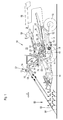
- FIG. 1 shows a harvesting machine in the form of a self-propelled combine harvester 10 with a frame 12 which is supported on the ground and driven by driven front wheels 14 and steerable rear wheels 16 on the ground.
- the wheels 14 are rotated by means not shown drive means in rotation to the combine 10 z. B. to move over a field to be harvested.
- directional details such as front and rear, refer to the direction of travel V of the combine harvester 10 in the harvesting operation.
- a crop gathering device 18 is detachably connected in the form of a cutter to harvest harvested crops in the form of crops or other threshable culottes from the field and feed them up and down by a feeder 20 to a multi-drum threshing unit.
- a threshing cylinder 22 arranged one behind the other - a threshing cylinder 22, a stripping drum 24, a superseding working conveyor drum 26, a Tangentialseparator 28 and a turning drum 30 includes.
- Downstream of the turning drum 30 is a straw shaker 32.
- the threshing drum 22 is surrounded by a concave 34 in its lower and rear area.
- a finger rake 38 is arranged below the conveyor drum 26.
- the mixture passing through the threshing concave 34, the separating basket 36 and the straw shakers 32, containing grains and impurities passes through the conveying bottoms 40, 42 into a Cleaning device 46.
- Grain cleaned by the cleaning device 46 is fed by means of a grain screw 48 to an elevator, not shown, which transports it into a grain tank 50.
- a tailing auger 52 returns unmanaged ear parts through another elevator, not shown, back into the threshing process.
- the chaff may be ejected at the rear of the screen by a rotating chaff spreader, or it may be discharged through a straw chopper (not shown) disposed downstream of the straw walker 32.
- the cleaned grain from the grain tank 50 may be unloaded by a discharge system with cross augers 54 and a discharge conveyor 56.
- the systems mentioned are driven by means of an internal combustion engine 58 and controlled and controlled by an operator from a driver's cab 60.
- the various devices for threshing, conveying, cleaning and separating are located within the frame 12. Outside the frame 12 is an outer shell, which is largely hinged.
- the multi-drum thresher shown here is only one embodiment. It could also be replaced by a single transverse threshing drum and a downstream separating device with a straw walker or one or more separating rotors or a threshing and separating device operating in the axial flow.
- a measuring device 62 is arranged below the roof, which is connected to an evaluation device 76.
- the measuring device 62 could also be attached to the Erntegutbergungs Surprise 18.
- the evaluation device 76 is connected to a speed setting device 78 (for example a swashplate adjusting device of a hydraulic pump, which is connected in a hydraulic fluid-conducting manner to a hydraulic motor that drives the wheels 14), which is set up to set the forwarding speed of the harvesting machine 10.
- the measuring device 62 is composed of a first transmitter 64, a first receiver 66, a second transmitter 68 and a second receiver 70, which are rotatable together by a pivot drive 74 about an approximately vertical, slightly forwardly inclined axis 72.
- electromagnetic waves emitted by the transmitters 64, 68 sweep one ahead of the range of measurement in front of the combine 10 by swiveling the transmitters 64, 68 and receivers 66, 70 (or merely their radiating and / or receiving elements) about the axis 72 , Thereby, the field 80 with the plants standing thereon 82 along a measuring direction, which is in a circular arc in front of extends the combine harvester 10, successively overlined.
- the first transmitter 64 emits electromagnetic first waves in the form of light in the (near) infrared or visible wave range, while the first receiver 66 is sensitive only to this light. Due to the chosen wavelength, the light is reflected by the plants 82 when it hits them. On the other hand, when the light hits the ground 84 between plants (eg in thin or missing stands), it is also reflected off the ground.
- the first transmitter 64 preferably comprises a laser for generating the light.
- the second transmitter 68 emits electromagnetic second waves in the micro or radar wave range, while the second receiver 70 is sensitive only to these waves.
- the wavelength is chosen such that most of the second waves penetrate the plants and are only reflected by the ground 84. A smaller proportion of the second waves is also reflected by the plants 82.
- the electromagnetic waves emitted by the transmitters 64, 68 reach the ground 84 at a distance of a few meters (for example 10 m) in the direction of travel of the combine 10 in front of the crop gathering device 18.
- the waves radiated by the transmitters 64, 68 can be modulated in amplitude or otherwise be to improve the signal-to-noise ratio.
- the evaluation device 76 accomplishes a detection of the distance between the measuring device 62 and the point at which the waves were respectively reflected.
- the pivot drive 74 can be designed as a servo or stepper motor and pivots the measuring device 62 (or only their elements radiating and / or receiving elements) continuously or stepwise by an angular range of for example 30 ° about the axis 72 back and forth.
- the evaluation device 76 is set up for each pivot angle of the measuring device 62 to detect the respective angle about the axis 72 and the transit time of the shaft or the distance of the receiver 66, 70 and transmitter 64, 68 from the reflection point. Subsequently, the pivot drive 74 is activated and the measuring device 62 is moved to another position.
- the evaluation device 74 has information about the respective angle of the measuring device 62, since it controls the pivot drive 74.
- the angle of the measuring device 62 about the axis 72 defines a measuring direction along which the transit times of the waves of the transmitter 64, 68 to the associated receiver 66, 70 are determined. It extends horizontally and in a circular arc transverse to the forward direction of the harvester 10th
- the signals of the first receiver 66 contain information about the height of the upper ends of the plants 82, because there they are primarily reflected. However, some first waves continue to penetrate further down in thinner stocks, some to the ground 84, and are only reflected there and received by the first receiver 66. In thinner stocks, therefore, the distances detected by the first receiver 66 vary more than in denser stands. These different variations of the distances depending on the population density are evaluated by the evaluation device 74 and used to determine the density of the plant population. Furthermore, the measured values of the second receiver 70 serve to determine a soil profile which, in conjunction with the heights of the tops of the plants 82 detected by the first receiver 66, is used for a more accurate determination of the plant heights, which are also used to determine the amount of plant.
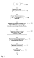
- step 102 the evaluation device 76 causes the pivoting drive 74, with the measuring device 62, a stepwise (or continuous) to sweep a certain angle range in front of the harvester 10.
- the respective swivel angle and distance measured values are stored by the evaluation device 76 in step 104.
- a profile of the plant heights along the measuring direction is calculated.
- the distance values (derived from reflections on tops of plants 82, which can be estimated approximately on the basis of travel time) of the first receiver 66 are first converted into the heights of the tops of the plants 82, which is based on the known geometry (height of the measuring device 62 via the ground 84 and the angle of radiation of the waves relative to the ground).
- the distance values of the second receiver 70 are converted into the heights of the ground 84, which is done on the basis of the known geometry (height of the measuring device 62 above the ground 84 and the angle of radiation of the waves relative to the ground).
- the heights of the soil are subtracted from the heights of the tops of the plants to produce the profile of plant heights.
- the first waves are reflected further ahead than the second waves (cf. FIG. 1 )
- the heights of the ground 84 detected by the second receiver 70 are first to be temporarily stored until exactly vertically superimposed height profiles of the tops of the plants 82 and of the ground 84 are subtracted from each other in the forward direction.
- the densities of the crop are determined.
- pre-echoes picked up by the second receiver 70 are also taken into account, because they are due to reflection of the second waves on the plants 82, which lie in time before the arrival of the second waves reflected at the ground 84 at the second receiver 70.
- These densities of the plant population are unitless and can be measured, for example, in units of percentages. They indicate what proportion of the detected vertical cross-sectional area of the plants 82 enveloped by the plants 82 in front of the measuring device 62 is actually occupied by plants 82.
- the vertical cross-sectional area occupied by plants 82 in front of the harvester 10 is then determined (by multiplying the plant heights by the plant density and integration via the measuring direction or vice versa) in step 110.
- This cross-sectional area has the dimension of a surface and can be converted into a volume by further integration along the forward direction and converted to a volume rate by multiplying by the propulsion rate.
- the mass density of the plants 82 is determined, ie their volume-related mass.
- the intensities of the waves received by the first receiver 66 can be taken into account (green plants generally have a higher density than dry, brown plants, cf. EP 1 271 139 A2 whose contents are incorporated by reference into the present documentation) and / or the intensities of the pre-echoes of the second waves, as described with respect to step 108.
- the rate of the crop 82 picked up by the combine 10 (in units of kg / s) is determined. Since this value is determined in a forward-looking manner, it can be used by the evaluation device 74 by means of the speed setting device 78 for the automatic adjustment of the forward speed of the combine harvester 10. At this point, the moisture of the crop can be taken into account, which can be determined in step 108 on the basis of the signals of the second receiver 70, whose pre-echoes not only on the density of the Plant life, but also depend on the moisture of the plants.
- the throughput (if necessary corrected on the basis of the humidity) can be converted directly into a propulsion speed value, or it (possibly corrected on the basis of the humidity) is first converted into a load of the cleaning, which is used to determine the propulsion speed, or he (possibly corrected by the humidity) is first converted into a loss value of the cleaning, which is used to determine the propulsion speed.
- the loss value can be calibrated by means of suitable sensors that directly detect the losses or a test shell.
- the throughput (especially at constant propulsion rates leading to time varying throughputs) can be used to automatically adjust equipment of the combine 10, such as the threshing drum gap or threshing drum speed, or to adjust the speed of the cleaning fan or screen opening.
- the measured values of the first receiver 66 can also be used for the automatic steering of the combine harvester 10.
- the height profiles of the soil 84 generated with the signals of the second receiver 70 can be used for a predictive, automatic height control of the harvesting device 18.
- Step 114 is followed again by step 102.
- the plant masses detectable by integrating the rates determined at step 114 may be georeferenced for precision farming purposes by means of position signals from a satellite-based positioning system (not shown).
- the present invention is suitable not only for standing plants as described above, but also for plants lying in a swath.
Applications Claiming Priority (1)
| Application Number | Priority Date | Filing Date | Title |
|---|---|---|---|
| DE201110017621 DE102011017621A1 (de) | 2011-04-27 | 2011-04-27 | Anordnung und Verfahren zur Erfassung der Menge von Pflanzen auf einem Feld |
Publications (2)
| Publication Number | Publication Date |
|---|---|
| EP2517549A1 true EP2517549A1 (fr) | 2012-10-31 |
| EP2517549B1 EP2517549B1 (fr) | 2015-11-04 |
Family
ID=45954394
Family Applications (1)
| Application Number | Title | Priority Date | Filing Date |
|---|---|---|---|
| EP12161450.7A Active EP2517549B1 (fr) | 2011-04-27 | 2012-03-27 | Agencement et procédé de détection de la quantité de plantes sur un champ |
Country Status (2)
| Country | Link |
|---|---|
| EP (1) | EP2517549B1 (fr) |
| DE (1) | DE102011017621A1 (fr) |
Cited By (18)
| Publication number | Priority date | Publication date | Assignee | Title |
|---|---|---|---|---|
| EP2681984A1 (fr) * | 2012-07-06 | 2014-01-08 | CLAAS Selbstfahrende Erntemaschinen GmbH | Moissonneuse-batteuse |
| US9282693B2 (en) | 2013-02-20 | 2016-03-15 | Deere & Company | Data encoding with planting attributes |
| US9807933B2 (en) | 2014-10-20 | 2017-11-07 | Cnh Industrial America Llc | Sensor equipped agricultural harvester |
| US9903979B2 (en) | 2014-09-23 | 2018-02-27 | Deere & Company | Yield estimation |
| EP3430881A1 (fr) | 2017-07-20 | 2019-01-23 | Deere & Company | Système pour optimiser des réglages de plate-forme sur la base d'une classification d'état de culture |
| EP3300580B1 (fr) | 2016-09-30 | 2019-04-10 | CLAAS Selbstfahrende Erntemaschinen GmbH | Moissonneuse-batteuse pourvue de barre de coupe et dispositif de commande d'une barre de coupe |
| EP3494771A1 (fr) * | 2017-12-07 | 2019-06-12 | CLAAS Selbstfahrende Erntemaschinen GmbH | Dispositif de hauteur de coupe automatique |
| EP3530098A1 (fr) * | 2018-02-23 | 2019-08-28 | CLAAS Selbstfahrende Erntemaschinen GmbH | Procédé de détermination de la densité de pâturage d'une culture |
| EP3530101A1 (fr) * | 2018-02-26 | 2019-08-28 | CLAAS Selbstfahrende Erntemaschinen GmbH | Récolteuse-hacheuse-chargeuse de fourrage automotrice |
| EP3542616A1 (fr) * | 2018-03-09 | 2019-09-25 | Deere & Company | Moissonneuse-batteuse avec réglage de la vitesse d'un ventilateur |
| EP3552474A1 (fr) | 2018-04-09 | 2019-10-16 | Deere & Company | Système pour commander un paramètre opérationnel d'une moissonneuse |
| EP3560314A1 (fr) | 2018-04-26 | 2019-10-30 | Deere & Company | Mécanisme de coupe à réglage automatique de l'orientation de dent de rabatteur |
| US10470365B2 (en) | 2015-11-24 | 2019-11-12 | Cnh Industrial America Llc | Monitoring system for an agricultural harvester and agricultural harvester |
| US10925211B2 (en) | 2017-05-18 | 2021-02-23 | Deere & Company | Self-learning system that takes into account corrective inputs for automatic control of an operating parameter of a crop transport or processing device |
| WO2022071373A1 (fr) * | 2020-09-30 | 2022-04-07 | 株式会社クボタ | Moissonneuse |
| CN114467688A (zh) * | 2020-10-26 | 2022-05-13 | 永嘉一本机械有限公司 | 一种农田喷洒装置 |
| BE1029377A1 (de) | 2021-05-28 | 2022-12-01 | Deere & Co | Feldhäcksler mit vorausschauender Ansteuerung des Bearbeitungsgrads eines Körnerprozessors |
| WO2023021005A1 (fr) * | 2021-08-17 | 2023-02-23 | Carl Geringhoff Gmbh & Co. Kommanditgesellschaft | Procédé d'évaluation d'image d'un paramètre de fonctionnement d'un outil frontal de récolte agricole |
Families Citing this family (9)
| Publication number | Priority date | Publication date | Assignee | Title |
|---|---|---|---|---|
| DE102013209197A1 (de) | 2013-05-17 | 2014-11-20 | Deere & Company | Erntemaschine mit vorausschauender Vortriebsgeschwindigkeitsregelung |
| DE102013214561B4 (de) | 2013-07-25 | 2022-03-24 | Maschinenfabrik Kemper Gmbh & Co. Kg | Feldhäcksler mit einer Anordnung zur Höhensteuerung eines Vordruckbügels eines Erntevorsatzes |
| DE102014208068A1 (de) | 2014-04-29 | 2015-10-29 | Deere & Company | Erntemaschine mit sensorbasierter Einstellung eines Arbeitsparameters |
| EP3195719B1 (fr) | 2016-01-20 | 2018-10-24 | CLAAS E-Systems KGaA mbH & Co KG | Machine agricole |
| DE102018104207A1 (de) * | 2018-02-23 | 2019-08-29 | Claas Selbstfahrende Erntemaschinen Gmbh | Selbstfahrende Erntemaschine |
| DE102018204301B4 (de) | 2018-03-21 | 2020-06-18 | Robert Bosch Gmbh | Verfahren zum Ermitteln einer Bestandhöhe von Feldpflanzen |
| DE102018006128B8 (de) * | 2018-08-03 | 2019-10-10 | Pepperl + Fuchs Gmbh | Landwirtschaftliche Erfassungsvorrichtung und Erfassungsverfahren zur Erfassung von landwirtschaftlichen Objekten |
| DE102019111040A1 (de) * | 2019-04-29 | 2020-10-29 | Claas Selbstfahrende Erntemaschinen Gmbh | Verfahren für den Betrieb einer selbstfahrenden landwirtschaftlichen Arbeitsmaschine |
| DE102021124481A1 (de) * | 2021-09-22 | 2023-03-23 | Claas E-Systems Gmbh | Verfahren zur Detektion des Bodenniveaus auf einer von einer landwirtschaftlichen Arbeitsmaschine zu bearbeitenden Fläche |
Citations (5)
| Publication number | Priority date | Publication date | Assignee | Title |
|---|---|---|---|---|
| EP0887660A2 (fr) | 1997-06-25 | 1998-12-30 | CLAAS Selbstfahrende Erntemaschinen GmbH | Dispositif à montage sur engins agricoles pour le balayage sans contact de contours sur la surface de la terre |
| EP1271139A2 (fr) | 2001-06-28 | 2003-01-02 | Deere & Company | Dispositif de mesure de la quantité de plantes en hauteur dans un champ |
| DE10214648A1 (de) | 2002-04-02 | 2003-10-16 | Claas Selbstfahr Erntemasch | Messeinrichtung an einer landwirtschaftlichen Maschine |
| DE10346541A1 (de) * | 2003-10-02 | 2005-07-14 | Institut für Agrartechnik Bornim e.V. | Einrichtung und Verfahren zum Messen der Ausbildung von Pflanzenbeständen |
| DE102008043716A1 (de) | 2008-11-13 | 2010-05-20 | Deere & Company, Moline | Vorrichtung und Verfahren zur Erfassung der Bestandsdichte von Pflanzen auf einem Feld |
-
2011
- 2011-04-27 DE DE201110017621 patent/DE102011017621A1/de not_active Withdrawn
-
2012
- 2012-03-27 EP EP12161450.7A patent/EP2517549B1/fr active Active
Patent Citations (5)
| Publication number | Priority date | Publication date | Assignee | Title |
|---|---|---|---|---|
| EP0887660A2 (fr) | 1997-06-25 | 1998-12-30 | CLAAS Selbstfahrende Erntemaschinen GmbH | Dispositif à montage sur engins agricoles pour le balayage sans contact de contours sur la surface de la terre |
| EP1271139A2 (fr) | 2001-06-28 | 2003-01-02 | Deere & Company | Dispositif de mesure de la quantité de plantes en hauteur dans un champ |
| DE10214648A1 (de) | 2002-04-02 | 2003-10-16 | Claas Selbstfahr Erntemasch | Messeinrichtung an einer landwirtschaftlichen Maschine |
| DE10346541A1 (de) * | 2003-10-02 | 2005-07-14 | Institut für Agrartechnik Bornim e.V. | Einrichtung und Verfahren zum Messen der Ausbildung von Pflanzenbeständen |
| DE102008043716A1 (de) | 2008-11-13 | 2010-05-20 | Deere & Company, Moline | Vorrichtung und Verfahren zur Erfassung der Bestandsdichte von Pflanzen auf einem Feld |
Cited By (26)
| Publication number | Priority date | Publication date | Assignee | Title |
|---|---|---|---|---|
| EP2681984A1 (fr) * | 2012-07-06 | 2014-01-08 | CLAAS Selbstfahrende Erntemaschinen GmbH | Moissonneuse-batteuse |
| US9282693B2 (en) | 2013-02-20 | 2016-03-15 | Deere & Company | Data encoding with planting attributes |
| US9903979B2 (en) | 2014-09-23 | 2018-02-27 | Deere & Company | Yield estimation |
| US10295703B2 (en) | 2014-09-23 | 2019-05-21 | Deere & Company | Yield estimation |
| US9807933B2 (en) | 2014-10-20 | 2017-11-07 | Cnh Industrial America Llc | Sensor equipped agricultural harvester |
| US10653063B2 (en) | 2015-11-24 | 2020-05-19 | Cnh Industrial America Llc | Monitoring system for an agricultural harvester and agricultural harvester |
| US10470365B2 (en) | 2015-11-24 | 2019-11-12 | Cnh Industrial America Llc | Monitoring system for an agricultural harvester and agricultural harvester |
| EP3300580B2 (fr) † | 2016-09-30 | 2022-04-27 | CLAAS Selbstfahrende Erntemaschinen GmbH | Moissonneuse-batteuse pourvue de barre de coupe et dispositif de commande d'une barre de coupe |
| EP3300580B1 (fr) | 2016-09-30 | 2019-04-10 | CLAAS Selbstfahrende Erntemaschinen GmbH | Moissonneuse-batteuse pourvue de barre de coupe et dispositif de commande d'une barre de coupe |
| US10925211B2 (en) | 2017-05-18 | 2021-02-23 | Deere & Company | Self-learning system that takes into account corrective inputs for automatic control of an operating parameter of a crop transport or processing device |
| EP3430881A1 (fr) | 2017-07-20 | 2019-01-23 | Deere & Company | Système pour optimiser des réglages de plate-forme sur la base d'une classification d'état de culture |
| US10757859B2 (en) | 2017-07-20 | 2020-09-01 | Deere & Company | System for optimizing platform settings based on crop state classification |
| EP3494771A1 (fr) * | 2017-12-07 | 2019-06-12 | CLAAS Selbstfahrende Erntemaschinen GmbH | Dispositif de hauteur de coupe automatique |
| EP3530098A1 (fr) * | 2018-02-23 | 2019-08-28 | CLAAS Selbstfahrende Erntemaschinen GmbH | Procédé de détermination de la densité de pâturage d'une culture |
| EP3530101A1 (fr) * | 2018-02-26 | 2019-08-28 | CLAAS Selbstfahrende Erntemaschinen GmbH | Récolteuse-hacheuse-chargeuse de fourrage automotrice |
| EP3542616A1 (fr) * | 2018-03-09 | 2019-09-25 | Deere & Company | Moissonneuse-batteuse avec réglage de la vitesse d'un ventilateur |
| US10897848B2 (en) | 2018-03-09 | 2021-01-26 | Deere & Company | Combine harvester with fan speed adjust |
| EP3552474A1 (fr) | 2018-04-09 | 2019-10-16 | Deere & Company | Système pour commander un paramètre opérationnel d'une moissonneuse |
| US11483972B2 (en) | 2018-04-09 | 2022-11-01 | Deere & Company | System for controlling an operative parameter of a harvesting header |
| EP3560314A1 (fr) | 2018-04-26 | 2019-10-30 | Deere & Company | Mécanisme de coupe à réglage automatique de l'orientation de dent de rabatteur |
| US11044847B2 (en) | 2018-04-26 | 2021-06-29 | Deere & Company | Cutter head with automatic setting of the reel finger orientation |
| WO2022071373A1 (fr) * | 2020-09-30 | 2022-04-07 | 株式会社クボタ | Moissonneuse |
| CN114467688A (zh) * | 2020-10-26 | 2022-05-13 | 永嘉一本机械有限公司 | 一种农田喷洒装置 |
| BE1029377A1 (de) | 2021-05-28 | 2022-12-01 | Deere & Co | Feldhäcksler mit vorausschauender Ansteuerung des Bearbeitungsgrads eines Körnerprozessors |
| DE102021113838A1 (de) | 2021-05-28 | 2022-12-01 | Deere & Company | Feldhäcksler mit vorausschauender Ansteuerung des Bearbeitungsgrads eines Körnerprozessors |
| WO2023021005A1 (fr) * | 2021-08-17 | 2023-02-23 | Carl Geringhoff Gmbh & Co. Kommanditgesellschaft | Procédé d'évaluation d'image d'un paramètre de fonctionnement d'un outil frontal de récolte agricole |
Also Published As
| Publication number | Publication date |
|---|---|
| EP2517549B1 (fr) | 2015-11-04 |
| DE102011017621A1 (de) | 2012-10-31 |
Similar Documents
| Publication | Publication Date | Title |
|---|---|---|
| EP2517549B1 (fr) | Agencement et procédé de détection de la quantité de plantes sur un champ | |
| EP2586286B1 (fr) | Agencement et procédé destinés à l'examen prévisionnel de plantes récoltées avec une moissonneuse | |
| EP2803256B1 (fr) | Moissonneuse dotée d'un réglage de la vitesse de propulsion anticipé | |
| EP2591654B1 (fr) | Agencement et procédé destinés à la documentation automatique de situations lors d'un travail agricole | |
| EP3662741B1 (fr) | Machine de travail agricole ainsi que procédé de fonctionnement d'une machine de travail agricole | |
| DE102008043716B4 (de) | Vorrichtung und Verfahren zur Erfassung der Bestandsdichte von Pflanzen auf einem Feld | |
| EP1271139B1 (fr) | Dispositif de mesure de la quantité de plantes en hauteur dans un champ | |
| DE69911302T2 (de) | Verfahren zur Messung von Erntegutfeuchtigkeit auf einer Erntemaschine | |
| BE1020387A5 (de) | Anordnung und verfahren zur selbsttätigen überladung von erntegut von einer erntemaschine auf ein transportfahrzeug. | |
| EP3300580B2 (fr) | Moissonneuse-batteuse pourvue de barre de coupe et dispositif de commande d'une barre de coupe | |
| DE102008017671B4 (de) | Messanordnung zur Massendurchsatzerfassung mit Massen- und Volumenmessung und darauf basierender Massendichtenbestimmung sowie Massendurchsatzangabe bei kleinen Durchsätzen anhand der zuletzt erfassten Massendichte | |
| DE102004038404B4 (de) | Einrichtung zur selbsttätigen Einstellung der Schnitthöhe eines Erntevorsatzes zur Ernte stängelartiger Pflanzen | |
| DE102014208068A1 (de) | Erntemaschine mit sensorbasierter Einstellung eines Arbeitsparameters | |
| DE102014204603B3 (de) | Verfahren zur selbsttätigen Einstellung von Dreschparametern eines Mähdreschers während der Ernte unter Verwendunq einer Anordnung zur Erkennung von Strohqualität | |
| EP3398420A1 (fr) | Procédé et dispositif de contrôle de la vitesse d'une presse à balles | |
| EP2873315B1 (fr) | Machine de récolte | |
| DE112014000906T5 (de) | Pflanzenweise Ernteguterfassungsauflösung | |
| DE112014000918T5 (de) | Ernteguterfassungsanzeige | |
| DE112014000914T5 (de) | Ernteguterfassung | |
| DE10211800A1 (de) | Einrichtung zur Erfassung des Vorhandenseins eines Gutstroms in einer Erntemaschine | |
| EP2845461B1 (fr) | Agencement de mesure de perte dans une moissonneuse-batteuse | |
| BE1029377B1 (de) | Feldhäcksler mit vorausschauender Ansteuerung des Bearbeitungsgrads eines Körnerprozessors | |
| DE102021117470A1 (de) | Verfahren und Anordnung zur Kontrolle eines Betriebsparameters eines Feldhäckslers | |
| EP3459337B1 (fr) | Engin agricole |
Legal Events
| Date | Code | Title | Description |
|---|---|---|---|
| PUAI | Public reference made under article 153(3) epc to a published international application that has entered the european phase |
Free format text: ORIGINAL CODE: 0009012 |
|
| AK | Designated contracting states |
Kind code of ref document: A1 Designated state(s): AL AT BE BG CH CY CZ DE DK EE ES FI FR GB GR HR HU IE IS IT LI LT LU LV MC MK MT NL NO PL PT RO RS SE SI SK SM TR |
|
| AX | Request for extension of the european patent |
Extension state: BA ME |
|
| 17P | Request for examination filed |
Effective date: 20130502 |
|
| GRAP | Despatch of communication of intention to grant a patent |
Free format text: ORIGINAL CODE: EPIDOSNIGR1 |
|
| GRAJ | Information related to disapproval of communication of intention to grant by the applicant or resumption of examination proceedings by the epo deleted |
Free format text: ORIGINAL CODE: EPIDOSDIGR1 |
|
| GRAP | Despatch of communication of intention to grant a patent |
Free format text: ORIGINAL CODE: EPIDOSNIGR1 |
|
| INTG | Intention to grant announced |
Effective date: 20150604 |
|
| RIC1 | Information provided on ipc code assigned before grant |
Ipc: A01D 41/127 20060101AFI20150522BHEP Ipc: A01D 41/14 20060101ALN20150522BHEP Ipc: A01D 43/08 20060101ALI20150522BHEP |
|
| INTG | Intention to grant announced |
Effective date: 20150618 |
|
| GRAS | Grant fee paid |
Free format text: ORIGINAL CODE: EPIDOSNIGR3 |
|
| GRAA | (expected) grant |
Free format text: ORIGINAL CODE: 0009210 |
|
| AK | Designated contracting states |
Kind code of ref document: B1 Designated state(s): AL AT BE BG CH CY CZ DE DK EE ES FI FR GB GR HR HU IE IS IT LI LT LU LV MC MK MT NL NO PL PT RO RS SE SI SK SM TR |
|
| REG | Reference to a national code |
Ref country code: GB Ref legal event code: FG4D Free format text: NOT ENGLISH |
|
| REG | Reference to a national code |
Ref country code: CH Ref legal event code: EP |
|
| REG | Reference to a national code |
Ref country code: AT Ref legal event code: REF Ref document number: 758529 Country of ref document: AT Kind code of ref document: T Effective date: 20151115 |
|
| REG | Reference to a national code |
Ref country code: IE Ref legal event code: FG4D Free format text: LANGUAGE OF EP DOCUMENT: GERMAN |
|
| REG | Reference to a national code |
Ref country code: DE Ref legal event code: R096 Ref document number: 502012005135 Country of ref document: DE |
|
| REG | Reference to a national code |
Ref country code: NL Ref legal event code: MP Effective date: 20151104 |
|
| REG | Reference to a national code |
Ref country code: LT Ref legal event code: MG4D |
|
| PG25 | Lapsed in a contracting state [announced via postgrant information from national office to epo] |
Ref country code: LT Free format text: LAPSE BECAUSE OF FAILURE TO SUBMIT A TRANSLATION OF THE DESCRIPTION OR TO PAY THE FEE WITHIN THE PRESCRIBED TIME-LIMIT Effective date: 20151104 Ref country code: IT Free format text: LAPSE BECAUSE OF FAILURE TO SUBMIT A TRANSLATION OF THE DESCRIPTION OR TO PAY THE FEE WITHIN THE PRESCRIBED TIME-LIMIT Effective date: 20151104 Ref country code: NO Free format text: LAPSE BECAUSE OF FAILURE TO SUBMIT A TRANSLATION OF THE DESCRIPTION OR TO PAY THE FEE WITHIN THE PRESCRIBED TIME-LIMIT Effective date: 20160204 Ref country code: IS Free format text: LAPSE BECAUSE OF FAILURE TO SUBMIT A TRANSLATION OF THE DESCRIPTION OR TO PAY THE FEE WITHIN THE PRESCRIBED TIME-LIMIT Effective date: 20160304 Ref country code: HR Free format text: LAPSE BECAUSE OF FAILURE TO SUBMIT A TRANSLATION OF THE DESCRIPTION OR TO PAY THE FEE WITHIN THE PRESCRIBED TIME-LIMIT Effective date: 20151104 Ref country code: NL Free format text: LAPSE BECAUSE OF FAILURE TO SUBMIT A TRANSLATION OF THE DESCRIPTION OR TO PAY THE FEE WITHIN THE PRESCRIBED TIME-LIMIT Effective date: 20151104 Ref country code: ES Free format text: LAPSE BECAUSE OF FAILURE TO SUBMIT A TRANSLATION OF THE DESCRIPTION OR TO PAY THE FEE WITHIN THE PRESCRIBED TIME-LIMIT Effective date: 20151104 |
|
| PG25 | Lapsed in a contracting state [announced via postgrant information from national office to epo] |
Ref country code: PT Free format text: LAPSE BECAUSE OF FAILURE TO SUBMIT A TRANSLATION OF THE DESCRIPTION OR TO PAY THE FEE WITHIN THE PRESCRIBED TIME-LIMIT Effective date: 20160304 Ref country code: SE Free format text: LAPSE BECAUSE OF FAILURE TO SUBMIT A TRANSLATION OF THE DESCRIPTION OR TO PAY THE FEE WITHIN THE PRESCRIBED TIME-LIMIT Effective date: 20151104 Ref country code: LV Free format text: LAPSE BECAUSE OF FAILURE TO SUBMIT A TRANSLATION OF THE DESCRIPTION OR TO PAY THE FEE WITHIN THE PRESCRIBED TIME-LIMIT Effective date: 20151104 Ref country code: PL Free format text: LAPSE BECAUSE OF FAILURE TO SUBMIT A TRANSLATION OF THE DESCRIPTION OR TO PAY THE FEE WITHIN THE PRESCRIBED TIME-LIMIT Effective date: 20151104 Ref country code: FI Free format text: LAPSE BECAUSE OF FAILURE TO SUBMIT A TRANSLATION OF THE DESCRIPTION OR TO PAY THE FEE WITHIN THE PRESCRIBED TIME-LIMIT Effective date: 20151104 Ref country code: GR Free format text: LAPSE BECAUSE OF FAILURE TO SUBMIT A TRANSLATION OF THE DESCRIPTION OR TO PAY THE FEE WITHIN THE PRESCRIBED TIME-LIMIT Effective date: 20160205 Ref country code: RS Free format text: LAPSE BECAUSE OF FAILURE TO SUBMIT A TRANSLATION OF THE DESCRIPTION OR TO PAY THE FEE WITHIN THE PRESCRIBED TIME-LIMIT Effective date: 20151104 |
|
| PG25 | Lapsed in a contracting state [announced via postgrant information from national office to epo] |
Ref country code: CZ Free format text: LAPSE BECAUSE OF FAILURE TO SUBMIT A TRANSLATION OF THE DESCRIPTION OR TO PAY THE FEE WITHIN THE PRESCRIBED TIME-LIMIT Effective date: 20151104 |
|
| REG | Reference to a national code |
Ref country code: DE Ref legal event code: R097 Ref document number: 502012005135 Country of ref document: DE |
|
| PG25 | Lapsed in a contracting state [announced via postgrant information from national office to epo] |
Ref country code: DK Free format text: LAPSE BECAUSE OF FAILURE TO SUBMIT A TRANSLATION OF THE DESCRIPTION OR TO PAY THE FEE WITHIN THE PRESCRIBED TIME-LIMIT Effective date: 20151104 Ref country code: RO Free format text: LAPSE BECAUSE OF FAILURE TO SUBMIT A TRANSLATION OF THE DESCRIPTION OR TO PAY THE FEE WITHIN THE PRESCRIBED TIME-LIMIT Effective date: 20151104 Ref country code: BE Free format text: LAPSE BECAUSE OF NON-PAYMENT OF DUE FEES Effective date: 20160331 Ref country code: SM Free format text: LAPSE BECAUSE OF FAILURE TO SUBMIT A TRANSLATION OF THE DESCRIPTION OR TO PAY THE FEE WITHIN THE PRESCRIBED TIME-LIMIT Effective date: 20151104 Ref country code: EE Free format text: LAPSE BECAUSE OF FAILURE TO SUBMIT A TRANSLATION OF THE DESCRIPTION OR TO PAY THE FEE WITHIN THE PRESCRIBED TIME-LIMIT Effective date: 20151104 Ref country code: SK Free format text: LAPSE BECAUSE OF FAILURE TO SUBMIT A TRANSLATION OF THE DESCRIPTION OR TO PAY THE FEE WITHIN THE PRESCRIBED TIME-LIMIT Effective date: 20151104 |
|
| PLBE | No opposition filed within time limit |
Free format text: ORIGINAL CODE: 0009261 |
|
| STAA | Information on the status of an ep patent application or granted ep patent |
Free format text: STATUS: NO OPPOSITION FILED WITHIN TIME LIMIT |
|
| 26N | No opposition filed |
Effective date: 20160805 |
|
| PG25 | Lapsed in a contracting state [announced via postgrant information from national office to epo] |
Ref country code: MC Free format text: LAPSE BECAUSE OF FAILURE TO SUBMIT A TRANSLATION OF THE DESCRIPTION OR TO PAY THE FEE WITHIN THE PRESCRIBED TIME-LIMIT Effective date: 20151104 Ref country code: LU Free format text: LAPSE BECAUSE OF FAILURE TO SUBMIT A TRANSLATION OF THE DESCRIPTION OR TO PAY THE FEE WITHIN THE PRESCRIBED TIME-LIMIT Effective date: 20160327 |
|
| REG | Reference to a national code |
Ref country code: CH Ref legal event code: PL |
|
| GBPC | Gb: european patent ceased through non-payment of renewal fee |
Effective date: 20160327 |
|
| PG25 | Lapsed in a contracting state [announced via postgrant information from national office to epo] |
Ref country code: SI Free format text: LAPSE BECAUSE OF FAILURE TO SUBMIT A TRANSLATION OF THE DESCRIPTION OR TO PAY THE FEE WITHIN THE PRESCRIBED TIME-LIMIT Effective date: 20151104 |
|
| REG | Reference to a national code |
Ref country code: IE Ref legal event code: MM4A |
|
| REG | Reference to a national code |
Ref country code: FR Ref legal event code: ST Effective date: 20161130 |
|
| PG25 | Lapsed in a contracting state [announced via postgrant information from national office to epo] |
Ref country code: FR Free format text: LAPSE BECAUSE OF NON-PAYMENT OF DUE FEES Effective date: 20160331 Ref country code: GB Free format text: LAPSE BECAUSE OF NON-PAYMENT OF DUE FEES Effective date: 20160327 Ref country code: LI Free format text: LAPSE BECAUSE OF NON-PAYMENT OF DUE FEES Effective date: 20160331 Ref country code: IE Free format text: LAPSE BECAUSE OF NON-PAYMENT OF DUE FEES Effective date: 20160327 Ref country code: CH Free format text: LAPSE BECAUSE OF NON-PAYMENT OF DUE FEES Effective date: 20160331 |
|
| PG25 | Lapsed in a contracting state [announced via postgrant information from national office to epo] |
Ref country code: MT Free format text: LAPSE BECAUSE OF FAILURE TO SUBMIT A TRANSLATION OF THE DESCRIPTION OR TO PAY THE FEE WITHIN THE PRESCRIBED TIME-LIMIT Effective date: 20151104 |
|
| REG | Reference to a national code |
Ref country code: AT Ref legal event code: MM01 Ref document number: 758529 Country of ref document: AT Kind code of ref document: T Effective date: 20170327 |
|
| PG25 | Lapsed in a contracting state [announced via postgrant information from national office to epo] |
Ref country code: CY Free format text: LAPSE BECAUSE OF FAILURE TO SUBMIT A TRANSLATION OF THE DESCRIPTION OR TO PAY THE FEE WITHIN THE PRESCRIBED TIME-LIMIT Effective date: 20151104 Ref country code: HU Free format text: LAPSE BECAUSE OF FAILURE TO SUBMIT A TRANSLATION OF THE DESCRIPTION OR TO PAY THE FEE WITHIN THE PRESCRIBED TIME-LIMIT; INVALID AB INITIO Effective date: 20120327 |
|
| PG25 | Lapsed in a contracting state [announced via postgrant information from national office to epo] |
Ref country code: MK Free format text: LAPSE BECAUSE OF FAILURE TO SUBMIT A TRANSLATION OF THE DESCRIPTION OR TO PAY THE FEE WITHIN THE PRESCRIBED TIME-LIMIT Effective date: 20151104 Ref country code: TR Free format text: LAPSE BECAUSE OF FAILURE TO SUBMIT A TRANSLATION OF THE DESCRIPTION OR TO PAY THE FEE WITHIN THE PRESCRIBED TIME-LIMIT Effective date: 20151104 |
|
| PG25 | Lapsed in a contracting state [announced via postgrant information from national office to epo] |
Ref country code: BG Free format text: LAPSE BECAUSE OF FAILURE TO SUBMIT A TRANSLATION OF THE DESCRIPTION OR TO PAY THE FEE WITHIN THE PRESCRIBED TIME-LIMIT Effective date: 20151104 |
|
| PG25 | Lapsed in a contracting state [announced via postgrant information from national office to epo] |
Ref country code: AT Free format text: LAPSE BECAUSE OF NON-PAYMENT OF DUE FEES Effective date: 20170327 |
|
| PG25 | Lapsed in a contracting state [announced via postgrant information from national office to epo] |
Ref country code: AL Free format text: LAPSE BECAUSE OF FAILURE TO SUBMIT A TRANSLATION OF THE DESCRIPTION OR TO PAY THE FEE WITHIN THE PRESCRIBED TIME-LIMIT Effective date: 20151104 |
|
| PGFP | Annual fee paid to national office [announced via postgrant information from national office to epo] |
Ref country code: DE Payment date: 20230221 Year of fee payment: 12 |