EP2515686B1 - Reactor system for electroporation - Google Patents
Reactor system for electroporation Download PDFInfo
- Publication number
- EP2515686B1 EP2515686B1 EP10805776.1A EP10805776A EP2515686B1 EP 2515686 B1 EP2515686 B1 EP 2515686B1 EP 10805776 A EP10805776 A EP 10805776A EP 2515686 B1 EP2515686 B1 EP 2515686B1
- Authority
- EP
- European Patent Office
- Prior art keywords
- electrodes
- central section
- reactor chamber
- reactor
- length
- Prior art date
- Legal status (The legal status is an assumption and is not a legal conclusion. Google has not performed a legal analysis and makes no representation as to the accuracy of the status listed.)
- Active
Links
Images
Classifications
-
- C—CHEMISTRY; METALLURGY
- C13—SUGAR INDUSTRY
- C13B—PRODUCTION OF SUCROSE; APPARATUS SPECIALLY ADAPTED THEREFOR
- C13B10/00—Production of sugar juices
- C13B10/08—Extraction of sugar from sugar beet with water
- C13B10/083—Treatment of sugar beet before extraction
-
- A—HUMAN NECESSITIES
- A23—FOODS OR FOODSTUFFS; TREATMENT THEREOF, NOT COVERED BY OTHER CLASSES
- A23N—MACHINES OR APPARATUS FOR TREATING HARVESTED FRUIT, VEGETABLES OR FLOWER BULBS IN BULK, NOT OTHERWISE PROVIDED FOR; PEELING VEGETABLES OR FRUIT IN BULK; APPARATUS FOR PREPARING ANIMAL FEEDING- STUFFS
- A23N1/00—Machines or apparatus for extracting juice
- A23N1/006—Machines or apparatus for extracting juice by electroplasmolysis
-
- A—HUMAN NECESSITIES
- A61—MEDICAL OR VETERINARY SCIENCE; HYGIENE
- A61N—ELECTROTHERAPY; MAGNETOTHERAPY; RADIATION THERAPY; ULTRASOUND THERAPY
- A61N1/00—Electrotherapy; Circuits therefor
- A61N1/18—Applying electric currents by contact electrodes
- A61N1/32—Applying electric currents by contact electrodes alternating or intermittent currents
- A61N1/327—Applying electric currents by contact electrodes alternating or intermittent currents for enhancing the absorption properties of tissue, e.g. by electroporation
Definitions
- the invention relates to a process for the electroporation of cells comprising sugar beet cells, wherein the electroporation is done in a reactor system suitable for electroporation of the cells.
- Such a reactor system is known from DE-A-10 2004 025 046 ; in this publication a reactor is disclosed wherein the electrodes of one or more high-voltage pulse generators are located in a reactor chamber, generating an electrical field across the width of the said reactor chamber.
- the known reactor system is suitable for the treatment of a large throughput by the use of more than one Marx generator but has the disadvantage that a considerable pulse current may flow out of the reactor chamber in the direction of the flow of the material, e.g. in the case of a voltage application asymmetric to ground. Hence, additional ground electrodes are required for safety reasons. Moreover, the efficiency of the systems is reduced due to regions with considerably low electric field below the threshold necessary for electroporation of cell material.
- the objective is achieved by a process for the electroporation of cells, wherein the cells comprise sugar beet cells, wherein the electroporation is done in a reactor system, comprising:
- an increase of velocity can easily lead to problems such as abrasion of the reactor system, pressure losses, or undesired stresses to the material conveyed through the reactor system.
- WO-A-98 14074 discloses a pulsed electric field treatment device for the sterilization and preservation of pumpable food products having at least two electrodes and an insulator. Each electrode includes an electrode flow chamber. The insulator is situated between the electrodes. A high voltage pulse generator applies a high voltage pulse of variable voltage, frequency and pulse duration to the electrodes.
- US-A-2008 279995 discloses a process for extracting useful substances from wine grapes by electroporation of the must produced from red and/or white grapes.
- the must is pumped or circulated before the pressing applied for must production through an installation or part of an installation and pulsed electric fields are applied therein to irreversibly rupture the biological cell walls of the grape skins.
- the device for carrying out must electroporation comprises a dielectric pipe, the flow duct for the must, in whose wall are arranged two mutually spaced electrodes to form a pulsed electric field between the electrodes.
- the device shows a strongly inhomogeneous field distribution in the flow volume.
- WO-A-2006 121397 relates to a method for continuous treatment of plant material such as for example root vegetables, comprising the steps of applying an electric field to the plant material, using such a field strength that pores are created in the cell membranes of the plant cellular material, resulting in an enhanced rate of mass transfer of intracellular and/or extracellular substances, which can be removed from said plant cellular material by washing in a liquid at low temperatures.
- US2008060637 relates to method and an installation for improving isolation and extraction of constituents from sugar beets (Beta vulgaris).
- the method comprises the steps of comminution of the sugar beets into beet chips while obtaining a chip-juice mixture, the addition of raw juice or water to the chips-juice mixture to obtain a prepared chips-juice mixture, the adjustment of the sugar beet bulk density to 400 to 800 kg/m 3 , electroporation of the prepared chip-juice mixture, and extraction of the electroporated chip-juice mixture.
- the present invention relates to a process for the electroporation of cells comprising sugar beet cells, done in a reactor system suitable for electroporation of the cells.
- reactor system as used herein encompasses not only a reactor chamber for carrying out an electroporation process but also all equipment, such as a pulse generator, that is essential for carrying out the said electroporation process in the reactor chamber.
- the electroporation that is carried out in the reactor has as purpose to irreversibly disrupt cells that are present in the reactor chamber.
- the power of the electroporation should therefore be greater as compared to known electroporation processes that are merely aimed at temporarily increasing the permeability of cell membranes without irreversible disruption of cells, a process also referred to as electropermeabilization.
- the reactor system in the process according to the invention comprises a reactor chamber; this is the chamber intended for carrying out an electroporation process.
- the reactor chamber in the reactor system according to the invention has a length and a width as important dimensions, whereby both the length as well as the width are meant herein to reflect the inner dimensions, i.e. without including dimensions of the material the chamber is constructed from.
- length and width as meant herein have the meaning normally associated with them by the person skilled in the art.
- the length is understood to be the inner distance between the ends that cap the cylinder as measured along the central axis of the cylinder, and the width is understood to be the diameter of the inner circular cross-section of the cylinder.
- the length is understood to be the inner distance between the ends of the duct and the width is understood to be the smaller of the two inner dimensions defined by the sides of the rectangular cross-section of the duct.
- cross-section has herein its usual meaning of being the intersection, or 'slice', of a body in 3-dimensional space with a plane.
- the reactor chamber should preferably be constructed from a material that is essentially an electrical insulator. This has the advantage that the electrodes, which will be described in more detail below, can be located and fixed in the reactor chamber without the need for further insulating measures.
- the reactor system of the invention enables the construction of reactor chambers having a large width.
- Said average width may in an embodiment of the invention vary between 0.05 and 2.00 m.
- the average width of the reactor chamber is at least 0.10, 0.15, 0.20, 0.25 or 0.30 m; the average width of the reactor chamber is preferably at most 2.00, 1.50, 1.40, 1.30, 1.20, 1.10, 1.00, 0.90, 0.80, or 0.75 m.
- the length of the reactor chamber may vary within a wide range; in one embodiment, the length lies between 0.75 and 5.0 m, more preferably between 0.80, 0.90. 1.00, 1.10, 1.20, 1.30, 1.40, 1.50 or 2.00 m and 4.5, 4.0, 3.5, or 3.0 m.
- the length of the reactor chamber is at least 1.5 times the width of the reactor chamber; more preferably, the length of the reactor chamber is at least 2.0, 2.5, 3.0, 3.5, 4.0, 4.5, 5.0, 5.5, 6.0, 6.5, 7.0, 7.5, 8.0, 8.5, 9.0, 9.5, or even at least 10 times the width of the reactor chamber. With an increasing ratio of length over width, the maintaining of a substantially homogeneous electrical field becomes more easy to implement.
- the pulse generators must each individually be able to supply at least an average power of 10 kW, 20 kW, 50 kW, 100 kW or 200 kW in order to achieve the desired electroporation effects. It is for example estimated that the electroporation of a total volume of 15,000 ton beet/day in a sugar factory may require an installed capacity of about 400 kW to 700 kW or more.
- the reactor system of the invention may be favourably implemented in this type of factory, whereby preferably two, four, or even six or eight pulse generators are used.
- the reactor chamber in the reactor system according to process of the invention has a central section along its length.
- a central section is a part of the reactor chamber that has the cross-section and at least a portion of the length of the reactor chamber as defining dimensions.
- the central section covers the whole of - and is thus identical to - the reactor chamber.
- the central section does not cover the whole of the reactor chamber; in this embodiment, a section at one end or at both ends of the reactor chamber - as seen in the length dimension - is not part of the central section.
- the volume of the central section is preferably between 30, 40, or 50 and 95, 90, 80, or 70 vol.% in relation to the volume of the reactor chamber as a whole.
- the average width of the central section should be within the ranges as given above for the average width of the reactor chamber.
- the reactor system comprises two pulse generators: a first pulse generator and a second pulse generator.
- a pulse generator as meant herein is a device capable of producing electrical high-voltage pulses to electrodes that are connected to the pulse generator. Such devices are as such known.
- One example of such a device is a Marx generator.
- the reactor system may comprise a third pulse generator, or even one or more further pulse generators. It is preferred that an even number of pulse generators is used; in one preferred embodiment, four pulse generators, preferably Marx generators, are used.
- oscillations between the pulse generators may occur in the case of a short time delay of one generator with respect to the others, so called jitter.
- These oscillations can be dampened advantageously by separating at least one electrode and connecting each generator output to one part of the separated electrode only.
- the resistance between the separate parts of the electrode may serve as a dampening element.
- This method is in principle known from literature, e.g. DE 10 2004 025 046 A1 .
- the resistance between two parts of one electrode e.g. A1 and B1
- the resistance between two parts of one electrode e.g. A1 and B1
- the ratio of the resistances between the two electrode groups A1 and B1 and the electrode pairs A1 and A2 is of importance.
- design rules can be based on the geometry only.
- the electrodes A1 and A2 are located at least partly and preferably essentially completely in the central section of the reactor chamber.
- the placement of the electrodes A1 and A2 should be such that the electrical field lines that are generated by a pulse fed to A1 and A2 by the first pulse generator can run substantially along the length of the central section.
- Electrodes A1 and A2 should thus be at a distance from each other when measured in the length direction of the central section. This distance should be at least equal to half the width of the reactor chamber; preferably the distance is more than 50, 60, 70, 80, 90, or even more than 95% of the length of the central section.
- electrodes A1 and A2 are located at essentially opposite ends of the length of the central section.
- the actual shape of the electrodes A1 and A2 may vary considerably. They are shaped in such a way that the shape does not negatively influence the functioning of the electroporation process, or even contributes positively to it by helping to ensure an as homogeneous as possible electrical field strength in the central section.
- One or both of the electrodes A1 and A2 may be in split form.
- electrode A1 is split into split-electrodes A1-i and A1-ii, whereby these are placed such that A2 lies between A1-i and A1-ii when evaluated along the length direction.
- electrode A1 (A2) is split into split-electrodes A1-i and A1-ii (A2-i and A2-ii), whereby these are placed such that A1-i and A1-ii (A2-i and A2-ii) lie on the same position when evaluated along the length direction.
- the electrodes B1 and B2 are located at least partly in the central section of the reactor chamber.
- the placement of the electrodes B1 and B2 should be such that the electrical field lines that are generated by a pulse fed to B1 and B2 by the first pulse generator can run substantially along the length of the central section.
- Electrodes B1 and B2 should thus be at a distance from each other when measured in the length direction of the central section. This distance should be at least equal to half the width of the reactor chamber; preferably the distance is more than 50, 60, 70, 80, 90, or even more than 95% of the length of the central section.
- electrodes B1 and B2 are located at essentially opposite ends of the length of the central section.
- the actual shape of the electrodes B1 and B2 may vary considerably. They are shaped in such a way that the shape does not negatively influence the functioning of the electroporation process, or even contributes positively to it by helping to ensure an as homogeneous as possible electrical field strength in the central section.
- One or both of the electrodes B1 and B2 may be in split form.
- electrode B1 is split into split-electrodes B1-i and B1-ii, whereby these are placed such that B2 lies between B1-i and B1-ii when evaluated along the length direction.
- electrode B1 is split into split-electrodes B1-i and B1-ii (B2-i and B2-ii), whereby these are placed such that B1-i and B1-ii (B2-i and B2-ii) lie on the same position when evaluated along the length direction.
- the pulse shapes applied to each pair of electrodes are substantially equal.
- This may be achieved by means that are as such known such as matching the electrode-pairs' impedances, the impedances of the pulse generators and the connecting circuits, or the total impedances of the circuits.
- this can be achieved by designing all electrodes equal and mounting them in the reactor chamber on a circle along the inner perimeter - whereby the term perimeter has its usual meaning of being a path that surrounds an area - with equal distance to each other, using pulse generators with the same inner impedance and using connecting circuits with the same geometric arrangement.
- electrodes A1 and B1 are placed such that they are electrically insulated from each other in the case of an empty reactor chamber; similarly, electrodes A2 and B2 are also insulated from each other. In another main embodiment, however, either electrodes A1 and B1 or electrodes A2 and B2 are joined into one combined electrode.
- the electrodes A1 and B1 are split into split-electrodes and the split-electrodes A1-i, ... A1-i n , B1-i, ... B1-i n (A2-i, ... A2-i n , B2-i, ... B2-i n ) are intermingled, whereby the mentioned electrodes are located in the reactor chamber in the central section and such, that they are, when measured in the length direction, less then a distance equalling half the width of the reactor chamber apart.
- An example of such a configuration is shown in Fig. 2 .
- the electrical field lines are distributed as homogeneously as possible in the central section, and they run essentially in the length direction. It is preferred that electrodes A1 and B1 are located within a short distance from each other when seen along the length of the central section. Preferably, A1 and B1 are located less than 20% or 10% of the width apart from each other along the length of the central section; more preferably, electrode A1 of the first pulse generator is on essentially the same place as electrode B1 of the second pulse generator, when measured along the length direction. Similarly, it is preferred that electrodes A2 and B2 are located within a short distance from each other when seen along the length of the central section.
- A2 and B2 are located less than 20% or 10% of the width apart from each other along the length of the central section; more preferably, electrode A2 of the first pulse generator is on essentially the same place as electrode B2 of the second pulse generator, when measured along the length direction.
- the electrodes will occupy a portion of the inner perimeter of the central section in the reactor chamber. Nevertheless, in case the electrodes are not joined there should be a space of at least 0.5 cm along the inner perimeter between them in order to allow for electrical insulation. Preferably, the said space is at least 1, 2, 3, 4 or even at least 5 cm. It is preferred that the electrodes are shaped in such a way that an electrode occupies / covers at most 50 % of the perimeter of the central section, when measured cross-sectionally (i.e. not in the length direction). More preferably, an electrode covers at most 49, 24, 11.5 or even at most 5.25 % of the perimeter.
- the electrodes cover a portion of the inner perimeter of the central section that is such that electrical field lines can be made to flow even substantially along the length of the central section and/or that the distribution of the electrical field lines can be substantially homogeneous.
- the electrodes stand out as little as possible from the perimeter towards the centre of the cross-section; this has the advantage that any flow of a product stream is hindered as little as possible.
- An electrode should preferably occupy less than 30% of the surface area of the cross section; more preferably, an electrode occupies less than 25, 20, 15, 10, or even less than 5% of the surface area of the cross section.
- the placement of the electrodes A1 and A2, when evaluated along the length direction relative to each other, is not twisted to a great extent.
- the placement of the electrodes A1 and A2 relative to each other along the inner perimeter varies less than 30%, preferably less than 20% or even 10% of the inner perimeter; most preferably, the said placement is essentially identical.
- the placement of the electrodes B1 and B2, when evaluated along the length direction relative to each other, is not twisted to a great extent.
- the placement of the electrodes B1 and B2 relative to each other along the inner perimeter varies less than 30%, preferably less than 20% or even 10%; most preferably, the said placement is essentially identical.
- each pair of electrodes powers a separate segment of the central section as seen along the length of the central section.
- both the first and the second pulse generator are high-voltage Marx generators. It is furthermore preferred that the Marx generators have means for triggering; such means are as such known as e.g. referred to in DE-A-10 2004 025 046 .
- the triggering means are preferably such that the Marx generators are ignited synchronously with a temporal uncertainty of not more than 30%, 20%, 10%, or even 5% of the pulse length. This has the advantage that a more stable operation may be achieved.
- the pulse shape of each pair of electrodes is substantially equal.
- the high-voltage Marx generators are bipolar, i.e. symmetric to ground. This involves the advantage of lower voltage to ground and, hence, less effort for insulation to ground. Additional ground electrodes at inlet and outlet and either shorter insulating elements between these electrodes and the high-voltage electrodes are then required or additional losses due to low-field regions reduce the efficiency.
- the high-voltage Marx generators are unipolar. The main advantage of this solution is, that apart from the mentioned losses no additional ground electrodes at inlet and outlet of the reactor are required. As a consequence, the electroporation reactor can be manufactured with insulating elements of one single type only. This is a cost-effective solution.
- unipolar Marx generators are commonly available on the market.
- the reactor system of the process according to the invention should be suitable for executing an electroporation process on a product, whereby the product contains plant cells comprising sugar beet cells.
- the disclosure also relates to a process for the electroporation of cells, preferably plant cells, whereby the electroporation is done in a reactor system according to the present invention.
- the electroporation process may according to the invention be executed in batch, or continuously.
- the shape, form and the location of inlets and outlets attached to the reactor chamber can vary considerably, depending on the way the electroporation process will be executed. For example and as is known, in a batch process an inlet for the product to be electroporated may function at the same time as outlet.
- the reactor system is suitable for executing an electroporation process in continuous fashion.
- the reactor chamber has an entrance and an exit.
- the central section lies between the entrance and the exit, such that a stream of a product can be made to flow through the central section on its way from the entrance to the exit.
- products that may be subjected to electroporation in this fashion are: sugar beets, an aqueous dispersion of sugar beets, and an aqueous dispersion of chips of sugar beet.
- a product essentially consisting of an aqueous dispersion of chips of sugar beet is made to flow through a reactor chamber in a reactor system according to the invention.
- the conductivity of the aqueous dispersion of chips of sugar beet preferably lies or is adjusted to a value between 0.2 and 10 mS/cm, more preferably between 2 and 6 mS/cm;
- the pH of the aqueous dispersion of chips of sugar beet preferably lies or is adjusted to a value lying between 7 and 14, more preferably between 9 and 11.
- the field strength as applied to the product in the central section lies between 0.1 and 20 kV/cm, more preferably between 3 and 6 kV/cm.
- the electroporation is carried out at a temperature that preferably lies between 0 and 65°C. More preferably the said temperature lies between 10 and 40°C; this has the advantage that certain beneficial subsequent operations, such as for example the extraction operation as disclosed in WO-A-2006/108481 , may be implemented without the need for significant intermediate temperature changes.
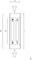
- Figure 1 shows the cross-section of a reactor chamber RC .
- the RC as shown may have a circular cross-section or be in the shape of a rectangular duct.
- the RC has a length l and a width W .
- the RC contains a central section (CS); in the CS, electrodes A1 and A2 are placed in the perimeter, as well as electrodes B1 and B2 .
- A1 and A2 are connected to a first pulse generator (not shown); likewise, B1 and B2 are connected to a second pulse generator (not shown).
- a product flow such as for example an aqueous dispersion of chips of sugar beet is made to flow through the entrance EN into the RC, then flow through the CS and then outwards out of the RC via the exit EX. While flowing through the CS, the product is exposed to the pulses of the electrical field that flow between the electrodes A1 and A2, and between B1 and B2. As a result, the product is electroporated. After leaving the RC via the exit EX, the electroporated chips of sugar beet may be subjected to an extraction process in order to recover sugar therefrom.
- a product flow such as for example an aqueous dispersion of chips of sugar beet is made to flow through the entrance EN into the RC, then flow through the CS and then outwards out of the RC via the exit EX. While flowing through the CS, the product is exposed to the pulses of the electrical field that flow between the electrodes A1 and A2, and between B1 and B2. As a result, the product is electrop
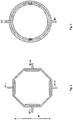
- Figure 2 shows a cross-section of a central section (CS) according to an embodiment of the invention, at the location along the length where the electrodes A1 and B1 are placed.
- the electrodes A1 and B1 are present in split form; furthermore, the split-electrodes are aligned along the perimeter of the cross section so as to disturb the product flow as little as possible.
- the width W of the RC, and thus of the CS too, is indicated in Figure 2 as well.
- the split-electrodes are located near to each other; it is however also possible that the split-electrodes are separated from each other, e.g. in the length direction with then the other electrode (A2 or B2) located in between.
- Figure 3 shows a cross-section of a central section (CS) according to a further embodiment of the invention, at the location along the length where the electrodes A1 and B1 are placed.
- the electrodes are shaped such that together they cover almost the complete inner perimeter of the CS, with only just enough space between them to allow for electrical insulation.
Landscapes
- Chemical & Material Sciences (AREA)
- Life Sciences & Earth Sciences (AREA)
- Biochemistry (AREA)
- Organic Chemistry (AREA)
- Engineering & Computer Science (AREA)
- Food Science & Technology (AREA)
- Polymers & Plastics (AREA)
- Physical Or Chemical Processes And Apparatus (AREA)
- Apparatus Associated With Microorganisms And Enzymes (AREA)
- Immobilizing And Processing Of Enzymes And Microorganisms (AREA)
Description
- The invention relates to a process for the electroporation of cells comprising sugar beet cells, wherein the electroporation is done in a reactor system suitable for electroporation of the cells.
- Such a reactor system is known from
DE-A-10 2004 025 046 ; in this publication a reactor is disclosed wherein the electrodes of one or more high-voltage pulse generators are located in a reactor chamber, generating an electrical field across the width of the said reactor chamber. - The known reactor system is suitable for the treatment of a large throughput by the use of more than one Marx generator but has the disadvantage that a considerable pulse current may flow out of the reactor chamber in the direction of the flow of the material, e.g. in the case of a voltage application asymmetric to ground. Hence, additional ground electrodes are required for safety reasons. Moreover, the efficiency of the systems is reduced due to regions with considerably low electric field below the threshold necessary for electroporation of cell material.
- It is an objective of the present invention to reduce or even eliminate the said disadvantage.
- The objective is achieved by a process for the electroporation of cells, wherein the cells comprise sugar beet cells, wherein the electroporation is done in a reactor system, comprising:
- a reactor chamber having a length and a width, whereby the reactor chamber contains a central section along its length, and whereby the length of the reactor chamber is at least 1.5 times the width of the reactor chamber;
- a first pulse generator to which two electrodes A1 and A2 are connected, whereby the electrodes A1 and A2 are located in the reactor chamber in the central section and such that they are, when measured in the length direction, at least a distance equalling half the width of the reactor chamber apart;
- a second pulse generator to which two electrodes B1 and B2 are connected, whereby the electrodes B1 and B2 are located in the reactor chamber in the central section and such that they are, when measured in the length direction, at least a distance equalling half the width of the reactor chamber apart,
- whereby the electrodes are shaped and placed such that the electrical field in at least the central section is substantially homogeneous, whereby the field lines run in essentially the length direction and whereby the field strength in the central section lies between 0.1 and 20 kV/cm.
- It is an advantage of the process according to the invention that by combining the method of split electrodes with an electric field orientation in the direction of the flow of the material, additional ground electrodes may by omitted.
- It is a further advantage of the process according to the invention that the regions - in particular in the central section - where the electric field is not strong enough to be suitable for electroporation can be reduced.
- It is another advantage of the process according to the invention that it is also suitable for larger-scale reactors, without having to resort to one single extremely powerful pulse generator.
- It is yet another advantage of the process according to the invention that it can be made suitable for processing high mass flows by increasing the width of the reactor chamber, thus avoiding largely or even completely the necessity to increase the velocity of the material conveyed through the reactor system. As is known, an increase of velocity can easily lead to problems such as abrasion of the reactor system, pressure losses, or undesired stresses to the material conveyed through the reactor system.
-
WO-A-98 14074 -
US-A-2008 279995 discloses a process for extracting useful substances from wine grapes by electroporation of the must produced from red and/or white grapes. The must is pumped or circulated before the pressing applied for must production through an installation or part of an installation and pulsed electric fields are applied therein to irreversibly rupture the biological cell walls of the grape skins. The device for carrying out must electroporation comprises a dielectric pipe, the flow duct for the must, in whose wall are arranged two mutually spaced electrodes to form a pulsed electric field between the electrodes. The device shows a strongly inhomogeneous field distribution in the flow volume. -
WO-A-2006 121397 relates to a method for continuous treatment of plant material such as for example root vegetables, comprising the steps of applying an electric field to the plant material, using such a field strength that pores are created in the cell membranes of the plant cellular material, resulting in an enhanced rate of mass transfer of intracellular and/or extracellular substances, which can be removed from said plant cellular material by washing in a liquid at low temperatures. -
US2008060637 relates to method and an installation for improving isolation and extraction of constituents from sugar beets (Beta vulgaris). The method comprises the steps of comminution of the sugar beets into beet chips while obtaining a chip-juice mixture, the addition of raw juice or water to the chips-juice mixture to obtain a prepared chips-juice mixture, the adjustment of the sugar beet bulk density to 400 to 800 kg/m3, electroporation of the prepared chip-juice mixture, and extraction of the electroporated chip-juice mixture. - The present invention relates to a process for the electroporation of cells comprising sugar beet cells, done in a reactor system suitable for electroporation of the cells. The term reactor system as used herein encompasses not only a reactor chamber for carrying out an electroporation process but also all equipment, such as a pulse generator, that is essential for carrying out the said electroporation process in the reactor chamber.
- As meant herein, the electroporation that is carried out in the reactor has as purpose to irreversibly disrupt cells that are present in the reactor chamber. The power of the electroporation should therefore be greater as compared to known electroporation processes that are merely aimed at temporarily increasing the permeability of cell membranes without irreversible disruption of cells, a process also referred to as electropermeabilization.
- As is known, in electroporation a voltage is applied to two electrodes, resulting in an electric field between these electrodes, whereby a product - i.e. the product to be electroporated - is placed between the electrodes. The applied electric field induces an electric potential across the membrane of cells; this leads to the formation of pores in the membranes, or, in case of the electric field is strong enough, to the destruction of the cell membranes. In the processes that may be executed in the reactor system of the invention, this destructive effect is desirable as it can lead to the release of valuable compounds from the cells; one example thereof is the release of sucrose (sugar) from sugar beet cells.
- The reactor system in the process according to the invention comprises a reactor chamber; this is the chamber intended for carrying out an electroporation process. As is usual for reactor chambers, the reactor chamber in the reactor system according to the invention has a length and a width as important dimensions, whereby both the length as well as the width are meant herein to reflect the inner dimensions, i.e. without including dimensions of the material the chamber is constructed from.
- The terms length and width as meant herein have the meaning normally associated with them by the person skilled in the art. For example, in case the reactor chamber is in the form of - or approximating - a cylinder, then the length is understood to be the inner distance between the ends that cap the cylinder as measured along the central axis of the cylinder, and the width is understood to be the diameter of the inner circular cross-section of the cylinder. In another example, if the reactor chamber is in the form of - or approximating - a rectangular duct then the length is understood to be the inner distance between the ends of the duct and the width is understood to be the smaller of the two inner dimensions defined by the sides of the rectangular cross-section of the duct. The term cross-section has herein its usual meaning of being the intersection, or 'slice', of a body in 3-dimensional space with a plane.
- The reactor chamber should preferably be constructed from a material that is essentially an electrical insulator. This has the advantage that the electrodes, which will be described in more detail below, can be located and fixed in the reactor chamber without the need for further insulating measures.
- It is an advantage of the reactor system of the process according to the invention that it may be implemented on commercial industrial scale whereby rather large volumes of a product can be electroporated. In particular, the reactor system of the invention enables the construction of reactor chambers having a large width. Said average width may in an embodiment of the invention vary between 0.05 and 2.00 m. Preferably, the average width of the reactor chamber is at least 0.10, 0.15, 0.20, 0.25 or 0.30 m; the average width of the reactor chamber is preferably at most 2.00, 1.50, 1.40, 1.30, 1.20, 1.10, 1.00, 0.90, 0.80, or 0.75 m.
- The length of the reactor chamber may vary within a wide range; in one embodiment, the length lies between 0.75 and 5.0 m, more preferably between 0.80, 0.90. 1.00, 1.10, 1.20, 1.30, 1.40, 1.50 or 2.00 m and 4.5, 4.0, 3.5, or 3.0 m. The length of the reactor chamber is at least 1.5 times the width of the reactor chamber; more preferably, the length of the reactor chamber is at least 2.0, 2.5, 3.0, 3.5, 4.0, 4.5, 5.0, 5.5, 6.0, 6.5, 7.0, 7.5, 8.0, 8.5, 9.0, 9.5, or even at least 10 times the width of the reactor chamber. With an increasing ratio of length over width, the maintaining of a substantially homogeneous electrical field becomes more easy to implement.
- Although it is an advantage of the present invention that not one pulse generator must carry the whole load, it is nevertheless foreseen that in certain main preferred embodiments of the invention on larger scale the pulse generators must each individually be able to supply at least an average power of 10 kW, 20 kW, 50 kW, 100 kW or 200 kW in order to achieve the desired electroporation effects. It is for example estimated that the electroporation of a total volume of 15,000 ton beet/day in a sugar factory may require an installed capacity of about 400 kW to 700 kW or more. In view of the technical and commercial limitations in the size and power of pulse generators, the reactor system of the invention may be favourably implemented in this type of factory, whereby preferably two, four, or even six or eight pulse generators are used.
- The reactor chamber in the reactor system according to process of the invention has a central section along its length. As meant herein, a central section is a part of the reactor chamber that has the cross-section and at least a portion of the length of the reactor chamber as defining dimensions. In one preferred embodiment, the central section covers the whole of - and is thus identical to - the reactor chamber. In another preferred embodiment, however, the central section does not cover the whole of the reactor chamber; in this embodiment, a section at one end or at both ends of the reactor chamber - as seen in the length dimension - is not part of the central section. The volume of the central section is preferably between 30, 40, or 50 and 95, 90, 80, or 70 vol.% in relation to the volume of the reactor chamber as a whole. The average width of the central section should be within the ranges as given above for the average width of the reactor chamber.
- The reactor system according to the process of the invention comprises two pulse generators: a first pulse generator and a second pulse generator. A pulse generator as meant herein is a device capable of producing electrical high-voltage pulses to electrodes that are connected to the pulse generator. Such devices are as such known. One example of such a device is a Marx generator. The reactor system may comprise a third pulse generator, or even one or more further pulse generators. It is preferred that an even number of pulse generators is used; in one preferred embodiment, four pulse generators, preferably Marx generators, are used.
- If two or more pulse generators are connected to one single pair of electrodes resulting in a parallel configuration of the generators, oscillations between the pulse generators may occur in the case of a short time delay of one generator with respect to the others, so called jitter. These oscillations can be dampened advantageously by separating at least one electrode and connecting each generator output to one part of the separated electrode only. Hence, the resistance between the separate parts of the electrode may serve as a dampening element. This method is in principle known from literature, e.g.
DE 10 2004 025 046 A1 . Usually the resistance between two parts of one electrode (e.g. A1 and B1) is in the order of several Ohm up to several 10 Ohm. For the design of an electroporation reactor the ratio of the resistances between the two electrode groups A1 and B1 and the electrode pairs A1 and A2 is of importance. Hence, design rules can be based on the geometry only. - To the first pulse generator, two electrodes are connected, herein named A1 and A2. According to the invention, the electrodes A1 and A2 are located at least partly and preferably essentially completely in the central section of the reactor chamber. The placement of the electrodes A1 and A2 should be such that the electrical field lines that are generated by a pulse fed to A1 and A2 by the first pulse generator can run substantially along the length of the central section. Electrodes A1 and A2 should thus be at a distance from each other when measured in the length direction of the central section. This distance should be at least equal to half the width of the reactor chamber; preferably the distance is more than 50, 60, 70, 80, 90, or even more than 95% of the length of the central section. In one preferred embodiment, electrodes A1 and A2 are located at essentially opposite ends of the length of the central section.
- The actual shape of the electrodes A1 and A2 may vary considerably. They are shaped in such a way that the shape does not negatively influence the functioning of the electroporation process, or even contributes positively to it by helping to ensure an as homogeneous as possible electrical field strength in the central section. One or both of the electrodes A1 and A2 may be in split form. In one embodiment, electrode A1 is split into split-electrodes A1-i and A1-ii, whereby these are placed such that A2 lies between A1-i and A1-ii when evaluated along the length direction. In another embodiment electrode A1 (A2) is split into split-electrodes A1-i and A1-ii (A2-i and A2-ii), whereby these are placed such that A1-i and A1-ii (A2-i and A2-ii) lie on the same position when evaluated along the length direction.
- To the second pulse generator, two electrodes are connected, herein named B1 and B2. According to the invention, the electrodes B1 and B2 are located at least partly in the central section of the reactor chamber. The placement of the electrodes B1 and B2 should be such that the electrical field lines that are generated by a pulse fed to B1 and B2 by the first pulse generator can run substantially along the length of the central section. Electrodes B1 and B2 should thus be at a distance from each other when measured in the length direction of the central section. This distance should be at least equal to half the width of the reactor chamber; preferably the distance is more than 50, 60, 70, 80, 90, or even more than 95% of the length of the central section. In one preferred embodiment, electrodes B1 and B2 are located at essentially opposite ends of the length of the central section.
- The actual shape of the electrodes B1 and B2 may vary considerably. They are shaped in such a way that the shape does not negatively influence the functioning of the electroporation process, or even contributes positively to it by helping to ensure an as homogeneous as possible electrical field strength in the central section. One or both of the electrodes B1 and B2 may be in split form. In one embodiment, electrode B1 is split into split-electrodes B1-i and B1-ii, whereby these are placed such that B2 lies between B1-i and B1-ii when evaluated along the length direction. In another embodiment electrode B1 (B2) is split into split-electrodes B1-i and B1-ii (B2-i and B2-ii), whereby these are placed such that B1-i and B1-ii (B2-i and B2-ii) lie on the same position when evaluated along the length direction.
- In the present invention it is advantageous if the pulse shapes applied to each pair of electrodes are substantially equal. This may be achieved by means that are as such known such as matching the electrode-pairs' impedances, the impedances of the pulse generators and the connecting circuits, or the total impedances of the circuits. In a simple design this can be achieved by designing all electrodes equal and mounting them in the reactor chamber on a circle along the inner perimeter - whereby the term perimeter has its usual meaning of being a path that surrounds an area - with equal distance to each other, using pulse generators with the same inner impedance and using connecting circuits with the same geometric arrangement.
- In one main embodiment, electrodes A1 and B1 are placed such that they are electrically insulated from each other in the case of an empty reactor chamber; similarly, electrodes A2 and B2 are also insulated from each other. In another main embodiment, however, either electrodes A1 and B1 or electrodes A2 and B2 are joined into one combined electrode.
- In another embodiment the electrodes A1 and B1 (A2 and B2) are split into split-electrodes and the split-electrodes A1-i, ... A1-in, B1-i, ... B1-in (A2-i, ... A2-in, B2-i, ... B2-in) are intermingled, whereby the mentioned electrodes are located in the reactor chamber in the central section and such, that they are, when measured in the length direction, less then a distance equalling half the width of the reactor chamber apart. An example of such a configuration is shown in
Fig. 2 . - The electrical field lines are distributed as homogeneously as possible in the central section, and they run essentially in the length direction. It is preferred that electrodes A1 and B1 are located within a short distance from each other when seen along the length of the central section. Preferably, A1 and B1 are located less than 20% or 10% of the width apart from each other along the length of the central section; more preferably, electrode A1 of the first pulse generator is on essentially the same place as electrode B1 of the second pulse generator, when measured along the length direction. Similarly, it is preferred that electrodes A2 and B2 are located within a short distance from each other when seen along the length of the central section. Preferably, A2 and B2 are located less than 20% or 10% of the width apart from each other along the length of the central section; more preferably, electrode A2 of the first pulse generator is on essentially the same place as electrode B2 of the second pulse generator, when measured along the length direction.
- Already by having a dimension due to their function, the electrodes will occupy a portion of the inner perimeter of the central section in the reactor chamber. Nevertheless, in case the electrodes are not joined there should be a space of at least 0.5 cm along the inner perimeter between them in order to allow for electrical insulation. Preferably, the said space is at least 1, 2, 3, 4 or even at least 5 cm. It is preferred that the electrodes are shaped in such a way that an electrode occupies / covers at most 50 % of the perimeter of the central section, when measured cross-sectionally (i.e. not in the length direction). More preferably, an electrode covers at most 49, 24, 11.5 or even at most 5.25 % of the perimeter.
- It is preferred that the electrodes cover a portion of the inner perimeter of the central section that is such that electrical field lines can be made to flow even substantially along the length of the central section and/or that the distribution of the electrical field lines can be substantially homogeneous. At the same time, it is preferred, in particular in case it is intended that a product stream flows through the reactor chamber, that the electrodes stand out as little as possible from the perimeter towards the centre of the cross-section; this has the advantage that any flow of a product stream is hindered as little as possible. An electrode should preferably occupy less than 30% of the surface area of the cross section; more preferably, an electrode occupies less than 25, 20, 15, 10, or even less than 5% of the surface area of the cross section.
- It is furthermore preferred that the placement of the electrodes A1 and A2, when evaluated along the length direction relative to each other, is not twisted to a great extent. Preferably, the placement of the electrodes A1 and A2 relative to each other along the inner perimeter varies less than 30%, preferably less than 20% or even 10% of the inner perimeter; most preferably, the said placement is essentially identical.
- Similarly, it is preferred that the placement of the electrodes B1 and B2, when evaluated along the length direction relative to each other, is not twisted to a great extent. Preferably, the placement of the electrodes B1 and B2 relative to each other along the inner perimeter varies less than 30%, preferably less than 20% or even 10%; most preferably, the said placement is essentially identical.
- When the placement along the perimeter of the electrodes A and the electrodes B is substantially or essentially identical, each pair of electrodes then powers a separate segment of the central section as seen along the length of the central section.
- In a main embodiment of the invention, both the first and the second pulse generator are high-voltage Marx generators. It is furthermore preferred that the Marx generators have means for triggering; such means are as such known as e.g. referred to in
DE-A-10 2004 025 046 . The triggering means are preferably such that the Marx generators are ignited synchronously with a temporal uncertainty of not more than 30%, 20%, 10%, or even 5% of the pulse length. This has the advantage that a more stable operation may be achieved. Preferably, the pulse shape of each pair of electrodes is substantially equal. - In another embodiment, the high-voltage Marx generators are bipolar, i.e. symmetric to ground. This involves the advantage of lower voltage to ground and, hence, less effort for insulation to ground. Additional ground electrodes at inlet and outlet and either shorter insulating elements between these electrodes and the high-voltage electrodes are then required or additional losses due to low-field regions reduce the efficiency. Alternatively, however, it was found that it can be advantageous if the high-voltage Marx generators are unipolar. The main advantage of this solution is, that apart from the mentioned losses no additional ground electrodes at inlet and outlet of the reactor are required. As a consequence, the electroporation reactor can be manufactured with insulating elements of one single type only. This is a cost-effective solution. Moreover, unipolar Marx generators are commonly available on the market.
-
DE 10 2004 025 046 A1 describes an electroporation chamber of rectangular or square cross section. When connecting such a chamber to a tube system, which typically has a round shaped cross section, connecting elements transferring the round shape to a rectangular or square shape of the same cross section area are required. To omit blocking of the material a smooth transition with constant cross section area is required. The use of a tube-like electroporation reactor with round shaped cross section omits the need for such connecting elements. - The reactor system of the process according to the invention should be suitable for executing an electroporation process on a product, whereby the product contains plant cells comprising sugar beet cells. The disclosure also relates to a process for the electroporation of cells, preferably plant cells, whereby the electroporation is done in a reactor system according to the present invention. The electroporation process may according to the invention be executed in batch, or continuously. The shape, form and the location of inlets and outlets attached to the reactor chamber can vary considerably, depending on the way the electroporation process will be executed. For example and as is known, in a batch process an inlet for the product to be electroporated may function at the same time as outlet. In one preferred embodiment, the reactor system is suitable for executing an electroporation process in continuous fashion. In this embodiment, the reactor chamber has an entrance and an exit. The central section lies between the entrance and the exit, such that a stream of a product can be made to flow through the central section on its way from the entrance to the exit. Examples of products that may be subjected to electroporation in this fashion are: sugar beets, an aqueous dispersion of sugar beets, and an aqueous dispersion of chips of sugar beet.
- In one main embodiment of the process for the electroporation of plant cells according to the invention, a product essentially consisting of an aqueous dispersion of chips of sugar beet is made to flow through a reactor chamber in a reactor system according to the invention. Upon entry into the reactor chamber, the conductivity of the aqueous dispersion of chips of sugar beet preferably lies or is adjusted to a value between 0.2 and 10 mS/cm, more preferably between 2 and 6 mS/cm; the pH of the aqueous dispersion of chips of sugar beet preferably lies or is adjusted to a value lying between 7 and 14, more preferably between 9 and 11. The field strength as applied to the product in the central section lies between 0.1 and 20 kV/cm, more preferably between 3 and 6 kV/cm. The electroporation is carried out at a temperature that preferably lies between 0 and 65°C. More preferably the said temperature lies between 10 and 40°C; this has the advantage that certain beneficial subsequent operations, such as for example the extraction operation as disclosed in
WO-A-2006/108481 , may be implemented without the need for significant intermediate temperature changes. - In the Figures:
-
Figure 1 shows a reactor chamber (RC) according to the invention; -
Figure 2 shows a cross-section of a central section (CS) according to the invention; -
Figure 3 shows a further cross section of a central section (CS) according to the invention. -
Figure 1 shows the cross-section of a reactor chamber RC. The RC as shown may have a circular cross-section or be in the shape of a rectangular duct. The RC has a length l and a width W. The RC contains a central section (CS); in the CS, electrodes A1 and A2 are placed in the perimeter, as well as electrodes B1 and B2. A1 and A2 are connected to a first pulse generator (not shown); likewise, B1 and B2 are connected to a second pulse generator (not shown). The RC ofFig. 1 is suitable for continuous operation; a product flow such as for example an aqueous dispersion of chips of sugar beet is made to flow through the entrance EN into the RC, then flow through the CS and then outwards out of the RC via the exit EX. While flowing through the CS, the product is exposed to the pulses of the electrical field that flow between the electrodes A1 and A2, and between B1 and B2. As a result, the product is electroporated. After leaving the RC via the exit EX, the electroporated chips of sugar beet may be subjected to an extraction process in order to recover sugar therefrom. -
Figure 2 shows a cross-section of a central section (CS) according to an embodiment of the invention, at the location along the length where the electrodes A1 and B1 are placed. In this embodiment, the electrodes A1 and B1 are present in split form; furthermore, the split-electrodes are aligned along the perimeter of the cross section so as to disturb the product flow as little as possible. The width W of the RC, and thus of the CS too, is indicated inFigure 2 as well. - In this embodiment, the split-electrodes are located near to each other; it is however also possible that the split-electrodes are separated from each other, e.g. in the length direction with then the other electrode (A2 or B2) located in between.
-
Figure 3 shows a cross-section of a central section (CS) according to a further embodiment of the invention, at the location along the length where the electrodes A1 and B1 are placed. In this embodiment, the electrodes are shaped such that together they cover almost the complete inner perimeter of the CS, with only just enough space between them to allow for electrical insulation.
Claims (12)
- Process for the electroporation of cells, wherein the cells comprise sugar beet cells, wherein the electroporation is done in a reactor system, comprising:• a reactor chamber having a length and a width, whereby the reactor chamber contains a central section along its length, and whereby the length of the reactor chamber is at least 1.5 times the width of the reactor chamber;• a first pulse generator to which two electrodes A1 and A2 are connected, whereby the electrodes A1 and A2 are located in the reactor chamber in the central section and such that they are, when measured in the length direction, at least a distance equalling half the width of the reactor chamber apart;• a second pulse generator to which two electrodes B1 and B2 are connected, whereby the electrodes B1 and B2 are located in the reactor chamber in the central section and such that they are, when measured in the length direction, at least a distance equalling half the width of the reactor chamber apart,• whereby the electrodes are shaped and placed such that the electrical field in at least the central section is substantially homogeneous, whereby the field lines run in essentially the length direction and whereby the field strength in the central section lies between 0.1 and 20 kV/cm.
- Process according to claim 1, wherein the reactor system comprises at least one further pulse generator, whereby two electrodes are connected to any further pulse generator, said electrodes being located in the reactor chamber in the central section and such that the two electrodes of a further pulse generator are, when measured in the length direction, at least a distance equalling half the width of the reactor chamber apart.
- Process according to claim 1 or 2, whereby in the reactor system at least one electrode of the first pulse generator is on the same place as an electrode of the second pulse generator and/or of a further pulse generator, when measured in the length direction.
- Process according to any one of claims 1 - 3, wherein in the reactor system for every pulse generator the electrodes attached to it are located in the reactor chamber in the central section such that they are, when measured in the length direction, at least a distance equalling 50% of the length of the central section apart.
- Process according to any one of claims 1 - 4, wherein the reactor system has an entrance and an exit, whereby the central section lies between the opening and the exit such that a stream of a product can flow from the entrance to the exit.
- Process according to any one of claims 1 - 5, whereby in the reactor system each pair of electrodes powers a separate segment along the length of the central section.
- Process according to any one of claims 1 - 6, whereby in the reactor system at least one electrode is split into two or more split-electrodes.
- Process according to any one of claims 1 - 7, whereby in the reactor system all pulse generators are bipolar pulse generators.
- Process according to any one of claims 1 - 7, whereby in the eactor system all pulse generators are unipolar pulse generators.
- Process according to claim 8 or 9, whereby in the reactor system all pulse generators are Marx generators.
- Process according to claims 8 - 10, whereby in the reactor system all pulse generators have means for triggering such that the pulse generators are fired synchronously with a temporal uncertainty of not more than 30 % of the pulse length.
- Process according to any one of claims 1 - 11, whereby in the reactor system the pulse shape of each pair of electrodes is substantially equal.
Priority Applications (2)
| Application Number | Priority Date | Filing Date | Title |
|---|---|---|---|
| EP10805776.1A EP2515686B1 (en) | 2009-12-23 | 2010-12-22 | Reactor system for electroporation |
| PL10805776T PL2515686T3 (en) | 2009-12-23 | 2010-12-22 | Reactor system for electroporation |
Applications Claiming Priority (3)
| Application Number | Priority Date | Filing Date | Title |
|---|---|---|---|
| EP09015926A EP2338356A1 (en) | 2009-12-23 | 2009-12-23 | Reactor system for electroporation |
| EP10805776.1A EP2515686B1 (en) | 2009-12-23 | 2010-12-22 | Reactor system for electroporation |
| PCT/EP2010/007854 WO2011076393A1 (en) | 2009-12-23 | 2010-12-22 | Reactor system for electroporation |
Publications (2)
| Publication Number | Publication Date |
|---|---|
| EP2515686A1 EP2515686A1 (en) | 2012-10-31 |
| EP2515686B1 true EP2515686B1 (en) | 2020-02-12 |
Family
ID=42238275
Family Applications (2)
| Application Number | Title | Priority Date | Filing Date |
|---|---|---|---|
| EP09015926A Ceased EP2338356A1 (en) | 2009-12-23 | 2009-12-23 | Reactor system for electroporation |
| EP10805776.1A Active EP2515686B1 (en) | 2009-12-23 | 2010-12-22 | Reactor system for electroporation |
Family Applications Before (1)
| Application Number | Title | Priority Date | Filing Date |
|---|---|---|---|
| EP09015926A Ceased EP2338356A1 (en) | 2009-12-23 | 2009-12-23 | Reactor system for electroporation |
Country Status (9)
| Country | Link |
|---|---|
| US (1) | US9340842B2 (en) |
| EP (2) | EP2338356A1 (en) |
| JP (2) | JP2013515464A (en) |
| CN (1) | CN102665453B (en) |
| CA (1) | CA2785486A1 (en) |
| EA (1) | EA021607B1 (en) |
| PL (1) | PL2515686T3 (en) |
| UA (1) | UA110468C2 (en) |
| WO (1) | WO2011076393A1 (en) |
Families Citing this family (2)
| Publication number | Priority date | Publication date | Assignee | Title |
|---|---|---|---|---|
| JP2022509497A (en) * | 2018-10-26 | 2022-01-20 | カイトペン コーポレイション | Devices, systems, and kits for electroporation, and how to use them. |
| USD965170S1 (en) | 2020-10-23 | 2022-09-27 | Life Technologies Corporation | Electroporation device |
Family Cites Families (17)
| Publication number | Priority date | Publication date | Assignee | Title |
|---|---|---|---|---|
| JPH0687782B2 (en) * | 1988-11-10 | 1994-11-09 | 浜松ホトニクス株式会社 | Cell electroporation method and device |
| JPH0351050A (en) * | 1989-07-20 | 1991-03-05 | Mitsubishi Heavy Ind Ltd | Virus devitalizing device |
| CN1195997A (en) * | 1995-03-10 | 1998-10-14 | 恩特雷麦德有限公司 | Flow Electroporation Chambers and Methods |
| US5690978A (en) | 1996-09-30 | 1997-11-25 | Ohio State University | High voltage pulsed electric field treatment chambers for the preservation of liquid food products |
| NL1010529C2 (en) * | 1998-11-11 | 2000-05-15 | Inst Voor Agrotech Onderzoek | Integrated modular construction of a pulsed electrical field system. |
| FR2792207B1 (en) * | 1999-04-15 | 2001-06-08 | Electricite De France | PROCESS FOR TREATING AN AQUEOUS FLOW BY ELECTROPULSATION WITH A FLOW PARALLEL FIELD, PULSATION CHAMBER AND APPLICATIONS |
| DE10144486C1 (en) * | 2001-09-10 | 2003-04-24 | Karlsruhe Forschzent | Process for the continuous non-thermal digestion and pasteurization of industrial quantities of organic process material by electroporation and reactor to carry out the process |
| NO20023398D0 (en) * | 2002-07-15 | 2002-07-15 | Osmotex As | Apparatus and method for transporting liquid through materials |
| JP2004248653A (en) * | 2003-02-22 | 2004-09-09 | Minoru Seki | Flow-type electrode device for electroporation and method for introducing substance into cell by using the same |
| DE102004013762B4 (en) * | 2004-03-20 | 2006-08-03 | Forschungszentrum Karlsruhe Gmbh | Process for better and gentle release of valuable ingredients from grapes and a must obtained from them |
| DE102004025046A1 (en) * | 2004-05-18 | 2005-12-15 | Forschungszentrum Karlsruhe Gmbh | Device for electroporating biological vegetable process material |
| DE102004028782B4 (en) * | 2004-06-16 | 2012-03-01 | Südzucker Aktiengesellschaft Mannheim/Ochsenfurt | Extraction of ingredients from beet pulp |
| JP4788002B2 (en) * | 2004-10-01 | 2011-10-05 | 独立行政法人農業生物資源研究所 | Method for introducing nucleic acid into cells using Agrobacterium, including the use of reduced pressure treatment / pressurization treatment |
| AU2006226753A1 (en) * | 2005-03-19 | 2006-09-28 | The Regents Of The University Of California | Ultra low strength electric field network-mediated ex vivo gene, protein and drug delivery in cells |
| DE102005017446B4 (en) | 2005-04-15 | 2008-06-05 | Südzucker AG Mannheim/Ochsenfurt | Temperature control during alkaline extraction |
| EP2941968A1 (en) * | 2005-05-12 | 2015-11-11 | Estrella Maarud Holding AS | Device for electroporation of potatoes and potato products |
| DE102008020429B4 (en) * | 2008-04-24 | 2012-02-02 | Südzucker AG Mannheim/Ochsenfurt | Process for the electroporation of beet pulp and apparatus for carrying out this process |
-
2009
- 2009-12-23 EP EP09015926A patent/EP2338356A1/en not_active Ceased
-
2010
- 2010-12-22 JP JP2012545155A patent/JP2013515464A/en active Pending
- 2010-12-22 EA EA201290545A patent/EA021607B1/en not_active IP Right Cessation
- 2010-12-22 UA UAA201208905A patent/UA110468C2/en unknown
- 2010-12-22 WO PCT/EP2010/007854 patent/WO2011076393A1/en not_active Ceased
- 2010-12-22 PL PL10805776T patent/PL2515686T3/en unknown
- 2010-12-22 CN CN201080058707.8A patent/CN102665453B/en not_active Expired - Fee Related
- 2010-12-22 CA CA2785486A patent/CA2785486A1/en not_active Abandoned
- 2010-12-22 EP EP10805776.1A patent/EP2515686B1/en active Active
- 2010-12-22 US US13/517,948 patent/US9340842B2/en active Active
-
2015
- 2015-12-11 JP JP2015242272A patent/JP6418649B2/en not_active Expired - Fee Related
Non-Patent Citations (1)
| Title |
|---|
| None * |
Also Published As
| Publication number | Publication date |
|---|---|
| US20120264187A1 (en) | 2012-10-18 |
| EP2338356A1 (en) | 2011-06-29 |
| WO2011076393A1 (en) | 2011-06-30 |
| CA2785486A1 (en) | 2011-06-30 |
| EA021607B1 (en) | 2015-07-30 |
| CN102665453A (en) | 2012-09-12 |
| JP2016063828A (en) | 2016-04-28 |
| CN102665453B (en) | 2016-02-24 |
| EA201290545A1 (en) | 2012-11-30 |
| EP2515686A1 (en) | 2012-10-31 |
| JP6418649B2 (en) | 2018-11-07 |
| UA110468C2 (en) | 2016-01-12 |
| JP2013515464A (en) | 2013-05-09 |
| US9340842B2 (en) | 2016-05-17 |
| PL2515686T3 (en) | 2020-09-07 |
Similar Documents
| Publication | Publication Date | Title |
|---|---|---|
| CA2780052C (en) | A pulsed electric field (pef) method for continuous enhanced extraction of oil and lipids from small aquatic plants | |
| CA2459475C (en) | Method and reactor for the non-thermal decomposition and pasteurization of organic process materials by electroporation | |
| CA2289829A1 (en) | Integrated modular design of a pulsed electrical field treatment chamber | |
| AU669725B2 (en) | High pulsed voltage systems for extending the shelf life of pumpable food products | |
| AU2005225488B9 (en) | Improved and more gentle process for extracting useful substances from grapes, grape must extracted therefrom and wine produced therefrom, as well as device for carrying out electroporation | |
| EP0594566B1 (en) | High pulsed voltage systems for extending the shelf life of pumpable food products | |
| US9247760B2 (en) | Method for extracting molecules of interest from grape pomace | |
| US20190314739A1 (en) | Extraction of Compounds from Cannabis | |
| US20210395723A1 (en) | Method for non-thermal extraction of phytochemicals from macroalgae | |
| US9340842B2 (en) | Reactor system for electroporation | |
| WO2008083549A1 (en) | A treating chamber for high-strength pulse electric field and high-frequency electric field fluid treating equipment | |
| CN114728259B (en) | pulsed electric field chamber | |
| CN207452135U (en) | Utilize the equipment of electroporation technology extraction Chinese medicine drug ingedient | |
| DE102007039115A1 (en) | Method and device for processing organic and / or inorganic media | |
| Bluhm et al. | Industrial-scale treatment of biological tissues with pulsed electric fields | |
| AU2013316183A1 (en) | Device and method for providing a high voltage pulsed electric field to a fluid | |
| Eshpulatov et al. | Determination of the influence of the electrohydraulic effect on succulent plant raw materials | |
| Novac et al. | An innovative and non-invasive technology for PEF food processing | |
| Yasuda et al. | Using underwater shockwaves for the development of processing devices for plant materials | |
| Oka et al. | Electric field pulse sterilization of liquid food | |
| RU2596987C1 (en) | Method and device for fragmentation and/or weakening of material by means of high-voltage pulses | |
| Gómez Galindo et al. | Design of equipment for pulsed electric field processing | |
| Corroto et al. | Pulsed Electric Field | |
| JPH02500563A (en) | Electric plasma separator for processing vegetable raw materials | |
| Režek Jambrak et al. | Comparison of high power ultrasound and cold plasma assisted extraction of glycosides from Stevia (Stevia rebaudiana) |
Legal Events
| Date | Code | Title | Description |
|---|---|---|---|
| PUAI | Public reference made under article 153(3) epc to a published international application that has entered the european phase |
Free format text: ORIGINAL CODE: 0009012 |
|
| 17P | Request for examination filed |
Effective date: 20120608 |
|
| AK | Designated contracting states |
Kind code of ref document: A1 Designated state(s): AL AT BE BG CH CY CZ DE DK EE ES FI FR GB GR HR HU IE IS IT LI LT LU LV MC MK MT NL NO PL PT RO RS SE SI SK SM TR |
|
| DAX | Request for extension of the european patent (deleted) | ||
| 17Q | First examination report despatched |
Effective date: 20160809 |
|
| STAA | Information on the status of an ep patent application or granted ep patent |
Free format text: STATUS: EXAMINATION IS IN PROGRESS |
|
| REG | Reference to a national code |
Ref country code: DE Ref legal event code: R079 Ref document number: 602010063066 Country of ref document: DE Free format text: PREVIOUS MAIN CLASS: A23N0001000000 Ipc: A61N0001320000 |
|
| GRAP | Despatch of communication of intention to grant a patent |
Free format text: ORIGINAL CODE: EPIDOSNIGR1 |
|
| STAA | Information on the status of an ep patent application or granted ep patent |
Free format text: STATUS: GRANT OF PATENT IS INTENDED |
|
| RIC1 | Information provided on ipc code assigned before grant |
Ipc: A61N 1/32 20060101AFI20190808BHEP Ipc: A23N 1/00 20060101ALI20190808BHEP Ipc: C13B 10/08 20110101ALI20190808BHEP |
|
| INTG | Intention to grant announced |
Effective date: 20190829 |
|
| GRAS | Grant fee paid |
Free format text: ORIGINAL CODE: EPIDOSNIGR3 |
|
| GRAA | (expected) grant |
Free format text: ORIGINAL CODE: 0009210 |
|
| STAA | Information on the status of an ep patent application or granted ep patent |
Free format text: STATUS: THE PATENT HAS BEEN GRANTED |
|
| AK | Designated contracting states |
Kind code of ref document: B1 Designated state(s): AL AT BE BG CH CY CZ DE DK EE ES FI FR GB GR HR HU IE IS IT LI LT LU LV MC MK MT NL NO PL PT RO RS SE SI SK SM TR |
|
| REG | Reference to a national code |
Ref country code: GB Ref legal event code: FG4D |
|
| REG | Reference to a national code |
Ref country code: CH Ref legal event code: EP |
|
| REG | Reference to a national code |
Ref country code: AT Ref legal event code: REF Ref document number: 1231290 Country of ref document: AT Kind code of ref document: T Effective date: 20200215 |
|
| REG | Reference to a national code |
Ref country code: IE Ref legal event code: FG4D |
|
| REG | Reference to a national code |
Ref country code: DE Ref legal event code: R096 Ref document number: 602010063066 Country of ref document: DE |
|
| REG | Reference to a national code |
Ref country code: NL Ref legal event code: FP |
|
| PG25 | Lapsed in a contracting state [announced via postgrant information from national office to epo] |
Ref country code: RS Free format text: LAPSE BECAUSE OF FAILURE TO SUBMIT A TRANSLATION OF THE DESCRIPTION OR TO PAY THE FEE WITHIN THE PRESCRIBED TIME-LIMIT Effective date: 20200212 Ref country code: FI Free format text: LAPSE BECAUSE OF FAILURE TO SUBMIT A TRANSLATION OF THE DESCRIPTION OR TO PAY THE FEE WITHIN THE PRESCRIBED TIME-LIMIT Effective date: 20200212 Ref country code: NO Free format text: LAPSE BECAUSE OF FAILURE TO SUBMIT A TRANSLATION OF THE DESCRIPTION OR TO PAY THE FEE WITHIN THE PRESCRIBED TIME-LIMIT Effective date: 20200512 |
|
| REG | Reference to a national code |
Ref country code: LT Ref legal event code: MG4D |
|
| PG25 | Lapsed in a contracting state [announced via postgrant information from national office to epo] |
Ref country code: GR Free format text: LAPSE BECAUSE OF FAILURE TO SUBMIT A TRANSLATION OF THE DESCRIPTION OR TO PAY THE FEE WITHIN THE PRESCRIBED TIME-LIMIT Effective date: 20200513 Ref country code: BG Free format text: LAPSE BECAUSE OF FAILURE TO SUBMIT A TRANSLATION OF THE DESCRIPTION OR TO PAY THE FEE WITHIN THE PRESCRIBED TIME-LIMIT Effective date: 20200512 Ref country code: HR Free format text: LAPSE BECAUSE OF FAILURE TO SUBMIT A TRANSLATION OF THE DESCRIPTION OR TO PAY THE FEE WITHIN THE PRESCRIBED TIME-LIMIT Effective date: 20200212 Ref country code: IS Free format text: LAPSE BECAUSE OF FAILURE TO SUBMIT A TRANSLATION OF THE DESCRIPTION OR TO PAY THE FEE WITHIN THE PRESCRIBED TIME-LIMIT Effective date: 20200612 Ref country code: SE Free format text: LAPSE BECAUSE OF FAILURE TO SUBMIT A TRANSLATION OF THE DESCRIPTION OR TO PAY THE FEE WITHIN THE PRESCRIBED TIME-LIMIT Effective date: 20200212 Ref country code: LV Free format text: LAPSE BECAUSE OF FAILURE TO SUBMIT A TRANSLATION OF THE DESCRIPTION OR TO PAY THE FEE WITHIN THE PRESCRIBED TIME-LIMIT Effective date: 20200212 |
|
| PG25 | Lapsed in a contracting state [announced via postgrant information from national office to epo] |
Ref country code: SM Free format text: LAPSE BECAUSE OF FAILURE TO SUBMIT A TRANSLATION OF THE DESCRIPTION OR TO PAY THE FEE WITHIN THE PRESCRIBED TIME-LIMIT Effective date: 20200212 Ref country code: LT Free format text: LAPSE BECAUSE OF FAILURE TO SUBMIT A TRANSLATION OF THE DESCRIPTION OR TO PAY THE FEE WITHIN THE PRESCRIBED TIME-LIMIT Effective date: 20200212 Ref country code: SK Free format text: LAPSE BECAUSE OF FAILURE TO SUBMIT A TRANSLATION OF THE DESCRIPTION OR TO PAY THE FEE WITHIN THE PRESCRIBED TIME-LIMIT Effective date: 20200212 Ref country code: RO Free format text: LAPSE BECAUSE OF FAILURE TO SUBMIT A TRANSLATION OF THE DESCRIPTION OR TO PAY THE FEE WITHIN THE PRESCRIBED TIME-LIMIT Effective date: 20200212 Ref country code: DK Free format text: LAPSE BECAUSE OF FAILURE TO SUBMIT A TRANSLATION OF THE DESCRIPTION OR TO PAY THE FEE WITHIN THE PRESCRIBED TIME-LIMIT Effective date: 20200212 Ref country code: EE Free format text: LAPSE BECAUSE OF FAILURE TO SUBMIT A TRANSLATION OF THE DESCRIPTION OR TO PAY THE FEE WITHIN THE PRESCRIBED TIME-LIMIT Effective date: 20200212 Ref country code: ES Free format text: LAPSE BECAUSE OF FAILURE TO SUBMIT A TRANSLATION OF THE DESCRIPTION OR TO PAY THE FEE WITHIN THE PRESCRIBED TIME-LIMIT Effective date: 20200212 Ref country code: CZ Free format text: LAPSE BECAUSE OF FAILURE TO SUBMIT A TRANSLATION OF THE DESCRIPTION OR TO PAY THE FEE WITHIN THE PRESCRIBED TIME-LIMIT Effective date: 20200212 Ref country code: PT Free format text: LAPSE BECAUSE OF FAILURE TO SUBMIT A TRANSLATION OF THE DESCRIPTION OR TO PAY THE FEE WITHIN THE PRESCRIBED TIME-LIMIT Effective date: 20200705 |
|
| REG | Reference to a national code |
Ref country code: DE Ref legal event code: R097 Ref document number: 602010063066 Country of ref document: DE |
|
| REG | Reference to a national code |
Ref country code: AT Ref legal event code: UEP Ref document number: 1231290 Country of ref document: AT Kind code of ref document: T Effective date: 20200212 |
|
| PLBE | No opposition filed within time limit |
Free format text: ORIGINAL CODE: 0009261 |
|
| STAA | Information on the status of an ep patent application or granted ep patent |
Free format text: STATUS: NO OPPOSITION FILED WITHIN TIME LIMIT |
|
| 26N | No opposition filed |
Effective date: 20201113 |
|
| PG25 | Lapsed in a contracting state [announced via postgrant information from national office to epo] |
Ref country code: IT Free format text: LAPSE BECAUSE OF FAILURE TO SUBMIT A TRANSLATION OF THE DESCRIPTION OR TO PAY THE FEE WITHIN THE PRESCRIBED TIME-LIMIT Effective date: 20200212 |
|
| PG25 | Lapsed in a contracting state [announced via postgrant information from national office to epo] |
Ref country code: SI Free format text: LAPSE BECAUSE OF FAILURE TO SUBMIT A TRANSLATION OF THE DESCRIPTION OR TO PAY THE FEE WITHIN THE PRESCRIBED TIME-LIMIT Effective date: 20200212 |
|
| REG | Reference to a national code |
Ref country code: CH Ref legal event code: PL |
|
| PG25 | Lapsed in a contracting state [announced via postgrant information from national office to epo] |
Ref country code: MC Free format text: LAPSE BECAUSE OF FAILURE TO SUBMIT A TRANSLATION OF THE DESCRIPTION OR TO PAY THE FEE WITHIN THE PRESCRIBED TIME-LIMIT Effective date: 20200212 |
|
| PG25 | Lapsed in a contracting state [announced via postgrant information from national office to epo] |
Ref country code: IE Free format text: LAPSE BECAUSE OF NON-PAYMENT OF DUE FEES Effective date: 20201222 Ref country code: LU Free format text: LAPSE BECAUSE OF NON-PAYMENT OF DUE FEES Effective date: 20201222 |
|
| PG25 | Lapsed in a contracting state [announced via postgrant information from national office to epo] |
Ref country code: LI Free format text: LAPSE BECAUSE OF NON-PAYMENT OF DUE FEES Effective date: 20201231 Ref country code: CH Free format text: LAPSE BECAUSE OF NON-PAYMENT OF DUE FEES Effective date: 20201231 |
|
| PGFP | Annual fee paid to national office [announced via postgrant information from national office to epo] |
Ref country code: FR Payment date: 20211224 Year of fee payment: 12 Ref country code: GB Payment date: 20211222 Year of fee payment: 12 Ref country code: AT Payment date: 20211222 Year of fee payment: 12 |
|
| PGFP | Annual fee paid to national office [announced via postgrant information from national office to epo] |
Ref country code: BE Payment date: 20211221 Year of fee payment: 12 |
|
| PGFP | Annual fee paid to national office [announced via postgrant information from national office to epo] |
Ref country code: PL Payment date: 20211210 Year of fee payment: 12 Ref country code: NL Payment date: 20211221 Year of fee payment: 12 |
|
| PG25 | Lapsed in a contracting state [announced via postgrant information from national office to epo] |
Ref country code: TR Free format text: LAPSE BECAUSE OF FAILURE TO SUBMIT A TRANSLATION OF THE DESCRIPTION OR TO PAY THE FEE WITHIN THE PRESCRIBED TIME-LIMIT Effective date: 20200212 Ref country code: MT Free format text: LAPSE BECAUSE OF FAILURE TO SUBMIT A TRANSLATION OF THE DESCRIPTION OR TO PAY THE FEE WITHIN THE PRESCRIBED TIME-LIMIT Effective date: 20200212 Ref country code: CY Free format text: LAPSE BECAUSE OF FAILURE TO SUBMIT A TRANSLATION OF THE DESCRIPTION OR TO PAY THE FEE WITHIN THE PRESCRIBED TIME-LIMIT Effective date: 20200212 |
|
| PG25 | Lapsed in a contracting state [announced via postgrant information from national office to epo] |
Ref country code: MK Free format text: LAPSE BECAUSE OF FAILURE TO SUBMIT A TRANSLATION OF THE DESCRIPTION OR TO PAY THE FEE WITHIN THE PRESCRIBED TIME-LIMIT Effective date: 20200212 Ref country code: AL Free format text: LAPSE BECAUSE OF FAILURE TO SUBMIT A TRANSLATION OF THE DESCRIPTION OR TO PAY THE FEE WITHIN THE PRESCRIBED TIME-LIMIT Effective date: 20200212 |
|
| REG | Reference to a national code |
Ref country code: NL Ref legal event code: MM Effective date: 20230101 |
|
| REG | Reference to a national code |
Ref country code: AT Ref legal event code: MM01 Ref document number: 1231290 Country of ref document: AT Kind code of ref document: T Effective date: 20221222 |
|
| GBPC | Gb: european patent ceased through non-payment of renewal fee |
Effective date: 20221222 |
|
| REG | Reference to a national code |
Ref country code: BE Ref legal event code: MM Effective date: 20221231 |
|
| PG25 | Lapsed in a contracting state [announced via postgrant information from national office to epo] |
Ref country code: NL Free format text: LAPSE BECAUSE OF NON-PAYMENT OF DUE FEES Effective date: 20230101 |
|
| PG25 | Lapsed in a contracting state [announced via postgrant information from national office to epo] |
Ref country code: GB Free format text: LAPSE BECAUSE OF NON-PAYMENT OF DUE FEES Effective date: 20221222 Ref country code: AT Free format text: LAPSE BECAUSE OF NON-PAYMENT OF DUE FEES Effective date: 20221222 |
|
| PG25 | Lapsed in a contracting state [announced via postgrant information from national office to epo] |
Ref country code: FR Free format text: LAPSE BECAUSE OF NON-PAYMENT OF DUE FEES Effective date: 20221231 Ref country code: BE Free format text: LAPSE BECAUSE OF NON-PAYMENT OF DUE FEES Effective date: 20221231 |
|
| PGFP | Annual fee paid to national office [announced via postgrant information from national office to epo] |
Ref country code: DE Payment date: 20231214 Year of fee payment: 14 |
|
| PG25 | Lapsed in a contracting state [announced via postgrant information from national office to epo] |
Ref country code: PL Free format text: LAPSE BECAUSE OF NON-PAYMENT OF DUE FEES Effective date: 20221222 |
|
| REG | Reference to a national code |
Ref country code: DE Ref legal event code: R119 Ref document number: 602010063066 Country of ref document: DE |
|
| PG25 | Lapsed in a contracting state [announced via postgrant information from national office to epo] |
Ref country code: DE Free format text: LAPSE BECAUSE OF NON-PAYMENT OF DUE FEES Effective date: 20250701 |