EP2515415A1 - Magnetic-resonant-coupling power transmission apparatus and magnetic-resonant-coupling power reception apparatus - Google Patents
Magnetic-resonant-coupling power transmission apparatus and magnetic-resonant-coupling power reception apparatus Download PDFInfo
- Publication number
- EP2515415A1 EP2515415A1 EP09852275A EP09852275A EP2515415A1 EP 2515415 A1 EP2515415 A1 EP 2515415A1 EP 09852275 A EP09852275 A EP 09852275A EP 09852275 A EP09852275 A EP 09852275A EP 2515415 A1 EP2515415 A1 EP 2515415A1
- Authority
- EP
- European Patent Office
- Prior art keywords
- coil
- power
- resonance
- magnetic resonance
- frequency
- Prior art date
- Legal status (The legal status is an assumption and is not a legal conclusion. Google has not performed a legal analysis and makes no representation as to the accuracy of the status listed.)
- Withdrawn
Links
Images











Classifications
-
- H—ELECTRICITY
- H02—GENERATION; CONVERSION OR DISTRIBUTION OF ELECTRIC POWER
- H02J—ELECTRIC POWER NETWORKS; CIRCUIT ARRANGEMENTS OR SYSTEMS FOR SUPPLYING OR DISTRIBUTING ELECTRIC POWER; SYSTEMS FOR STORING ELECTRIC ENERGY
- H02J50/00—Circuit arrangements or systems for wireless supply or distribution of electric power
- H02J50/10—Circuit arrangements or systems for wireless supply or distribution of electric power using inductive coupling
- H02J50/12—Circuit arrangements or systems for wireless supply or distribution of electric power using inductive coupling of the resonant type
-
- H—ELECTRICITY
- H02—GENERATION; CONVERSION OR DISTRIBUTION OF ELECTRIC POWER
- H02J—ELECTRIC POWER NETWORKS; CIRCUIT ARRANGEMENTS OR SYSTEMS FOR SUPPLYING OR DISTRIBUTING ELECTRIC POWER; SYSTEMS FOR STORING ELECTRIC ENERGY
- H02J50/00—Circuit arrangements or systems for wireless supply or distribution of electric power
- H02J50/60—Circuit arrangements or systems for wireless supply or distribution of electric power responsive to the presence of foreign objects, e.g. detection of living beings
-
- H—ELECTRICITY
- H02—GENERATION; CONVERSION OR DISTRIBUTION OF ELECTRIC POWER
- H02J—ELECTRIC POWER NETWORKS; CIRCUIT ARRANGEMENTS OR SYSTEMS FOR SUPPLYING OR DISTRIBUTING ELECTRIC POWER; SYSTEMS FOR STORING ELECTRIC ENERGY
- H02J50/00—Circuit arrangements or systems for wireless supply or distribution of electric power
- H02J50/80—Circuit arrangements or systems for wireless supply or distribution of electric power involving the exchange of data, concerning supply or distribution of electric power, between transmitting devices and receiving devices
-
- H—ELECTRICITY
- H02—GENERATION; CONVERSION OR DISTRIBUTION OF ELECTRIC POWER
- H02J—ELECTRIC POWER NETWORKS; CIRCUIT ARRANGEMENTS OR SYSTEMS FOR SUPPLYING OR DISTRIBUTING ELECTRIC POWER; SYSTEMS FOR STORING ELECTRIC ENERGY
- H02J50/00—Circuit arrangements or systems for wireless supply or distribution of electric power
- H02J50/90—Circuit arrangements or systems for wireless supply or distribution of electric power involving detection or optimisation of position, e.g. alignment
-
- H—ELECTRICITY
- H03—ELECTRONIC CIRCUITRY
- H03H—IMPEDANCE NETWORKS, e.g. RESONANT CIRCUITS; RESONATORS
- H03H3/00—Apparatus or processes specially adapted for the manufacture of impedance networks, resonating circuits, resonators
- H03H3/007—Apparatus or processes specially adapted for the manufacture of impedance networks, resonating circuits, resonators for the manufacture of electromechanical resonators or networks
- H03H3/0072—Apparatus or processes specially adapted for the manufacture of impedance networks, resonating circuits, resonators for the manufacture of electromechanical resonators or networks of microelectro-mechanical resonators or networks
- H03H3/0076—Apparatus or processes specially adapted for the manufacture of impedance networks, resonating circuits, resonators for the manufacture of electromechanical resonators or networks of microelectro-mechanical resonators or networks for obtaining desired frequency or temperature coefficients
- H03H3/0077—Apparatus or processes specially adapted for the manufacture of impedance networks, resonating circuits, resonators for the manufacture of electromechanical resonators or networks of microelectro-mechanical resonators or networks for obtaining desired frequency or temperature coefficients by tuning of resonance frequency
Definitions
- the embodiments discussed herein relate to a magnetic resonance power transmitter and a magnetic resonance power receiver used for wireless power transmission by magnetic resonance.
- the magnetic resonance wireless power transmission system has a power transmitter including a resonance coil and a power receiver including a resonance coil, and the resonance coil included in the power transmitter and the resonance coil included in the power receiver have the same resonance frequency.
- the wireless power transmission system there exist, for example, a wireless power transmission system using electric waves and a wireless power transmission system using electromagnetic induction in addition to the magnetic resonance wireless power transmission system.
- the magnetic resonance wireless power transmission system has, for example, the following merits. It is possible for the magnetic resonance wireless power transmission system to transmit large power compared to the wireless power transmission system using electric waves. Further, it is possible for the magnetic resonance wireless power transmission system to extend the power transmission distance compared to the wireless power transmission system using electromagnetic induction and also possible to downsize each resonance coil of the power transmitter and the power receiver.
- the wireless power transmission system it is necessary to perform wireless communication between the power transmitter and the power receiver in order to grasp the transmitted power to determine an electric power rate in accordance with the transmitted power and to prevent power transmission to other than the transmission target by authenticating the power receiver.
- the magnetic resonance power transmitter includes a resonance coil, an alternating current power source configured to cause the resonance coil to generate an alternating current, and a frequency changer configured to change, based on communication data, a frequency of the alternating current that the alternating current power source causes the resonance coil to generate.
- the magnetic resonance power transmitter and the magnetic resonance power receiver disclosed herein it is made possible to reduce the costs of the magnetic resonance power transmitter and the magnetic resonance power receiver including the communication function.
- FIG. 1 illustrates an example of a magnetic resonance wireless power transmission system according to a first embodiment.
- a magnetic resonance wireless power transmission system 10 includes a magnetic resonance power transmitter 100 configured to transmit power and a magnetic resonance power receiver 200 configured to receive power transmitted from the magnetic resonance power transmitter 100.
- the magnetic resonance power transmitter 100 has a resonance coil 110, a coil 120 configured to supply power to the resonance coil 110 by electromagnetic induction, and an alternating current power source 130 configured to cause the coil 120 to generate an alternating current.
- the resonance coil 110 As the material of the resonance coil 110 , for example, copper (Cu) is used. As the resonance coil 110, for example, a helical coil having a diameter of 30 cm is used.
- the resonance coil 110 configures an LC resonance circuit having an inductance L and a capacitance C and has the resonance frequency same as the transmission frequency.
- the transmission frequency refers to the frequency of transmission wave used to transmit power from the magnetic resonance power transmitter 100 to the magnetic resonance power receiver 200.
- the resonance frequency of the resonance coil 110 is, for example, 10 MHz. Further, in the resonance coil 110, the capacitance C is obtained by the floating capacitance of the resonance coil 110, but it may also be possible to obtain the capacitance C by providing a capacitor between coil wires of the resonance coil 110.
- the resonance coil 110 When power is supplied from the coil 120 by electromagnetic induction and an alternating current having the same frequency as the resonance frequency flows, the resonance coil 110 performs wireless power transmission by magnetic resonance toward the magnetic resonance power receiver 200.
- the alternating current power source 130 connects with the coil 120 and causes the coil 120 to generate an alternating current having the same frequency as the transmission frequency, for example, 10 MHz.
- the coil 120 As the material of the coil 120, for example, copper (Cu) is used.
- the coil 120 supplies power to the resonance coil 110 by electromagnetic induction and causes the resonance coil 110 to generate an alternating current.
- the frequency of the alternating current flowing through the coil 120 agrees with the frequency of the alternating current generated in the resonance coil 110. That is, when an alternating current having the same frequency as the transmission frequency, for example, 10 MHz, is supplied to the coil 120, an alternating current having the same frequency as the transmission frequency, for example, 10 MHz, flows through the resonance coil 110.
- the resonance coil 110 may also be possible to supply power directly to the resonance coil 110 from the alternating current power source 130 by connecting the alternating current power source 130 to the resonance coil 110.
- the magnetic resonance power transmitter 100 has a frequency changer 140 configured to change the frequency of an alternating current that the alternating current power source 130 causes the coil 120 to generate.
- the frequency changer 140 modulates, based on communication data, the frequency of an alternating current generated by the alternating current power source 130 when the magnetic resonance power transmitter 100 and the magnetic resonance power receiver 200 communicate with each other.
- the frequency of the alternating current generated by the alternating current power source 130 is modulated as described above, the amount of power transmitted by the resonance coil 110 is modulated accordingly.
- communication data is transmitted from the resonance coil 110 to the magnetic resonance power receiver 200 as a modulated signal of the amount of power.
- the frequency changer 140 maintains the frequency of the alternating current generated by the alternating current power source 130 to the transmission frequency at the time of power transmission.
- the magnetic resonance power receiver 200 has a resonance coil 210 to which power is transmitted from the resonance coil 110 of the magnetic resonance power transmitter 100 and a coil 220 to which the power transmitted to the resonance coil 210 is supplied.
- the distance between the resonance coil 110 and the resonance coil 210 at the time of power transmission is supposed to be, for example, about several tens cm to 2 m.
- the resonance coil 210 As the material of the resonance coil 210 , for example, copper (Cu) is used. As the resonance coil 210, for example, a helical coil having a diameter of 30 cm is used. The resonance coil 210 configures an LC resonance circuit having the inductance L and the capacitance C and has the resonance frequency same as the transmission frequency. That is, the resonance frequency of the resonance coil 210 agrees with the resonance frequency of the resonance coil 110.
- Cu copper
- the resonance coil 210 for example, a helical coil having a diameter of 30 cm is used.
- the resonance coil 210 configures an LC resonance circuit having the inductance L and the capacitance C and has the resonance frequency same as the transmission frequency. That is, the resonance frequency of the resonance coil 210 agrees with the resonance frequency of the resonance coil 110.
- the resonance frequency of the resonance coil 210 is, for example, 10 MHz.
- the capacitance C is obtained by the floating capacitance of the resonance coil 210, but it may also be possible to obtain the capacitance C by providing a capacitor between coil wires of the resonance coil 210.
- an alternating current having the same frequency as the transmission frequency flows through the resonance coil 210.
- a modulated signal of the amount of power is transmitted from the resonance coil 110 of the magnetic resonance power transmitter 100 at the time of communication and an alternating current in the magnitude according to the modulated signal flows therethrough. That is, the modulated signal of the amount of power is propagated from the resonance coil 110 to the resonance coil 210.
- the material of the coil 220 for example, copper (Cu) is used.
- Cu copper
- the supply of power from the resonance coil 210 is not via a wire etc. but by electromagnetic induction. Hence, it is possible to prevent resistance from being added to the resonance coil 210, thus enabling obtaining of the high precision resonance coil 210 having the resonance frequency same as the target frequency.
- an alternating current in the magnitude according to the modulated signal of the amount of power propagated to the resonance coil 110 flows at the time of communication. That is, the modulated signal of the amount of power is propagated from the resonance coil 110 to the coil 220.
- the magnetic resonance power receiver 200 has a power receiver 230 configured to receive power supplied to the coil 220 and a detector 240 configured to detect the magnitude of power supplied to the coil 220.
- the power receiver 230 for example, a power consumer or a power accumulator, such as a battery, is used.
- a power consumer or a power accumulator such as a battery
- the detector 240 detects the modulated signal of the amount of power propagated to the coil 220 at the time of communication and generates demodulated data including, for example, 1-bit data or 2-bit data by comparing the detected modulated signal with a reference amount of power.
- both the resonance coil 110 and the resonance coil 210 have the resonance frequency same as the transmission frequency.
- power transmission by magnetic resonance is performed between the resonance coil 110 and the resonance coil 210 and an alternating current flows through the resonance coil 210. In this manner, power is transmitted wirelessly from the resonance coil 110 to the resonance coil 210.
- the frequency changer 140 modulates the frequency of the alternating current generated in the coil 120 based on communication data and thus the modulated signal of the amount of power is transmitted from the resonance coil 110 to the resonance coil 210.
- the modulated signal of the amount of power transmitted to the resonance coil 210 is demodulated by the detector 240 and demodulated data is generated. In this manner, wireless communication of data from the magnetic resonance power transmitter 100 to the magnetic resonance power receiver 200 is performed.
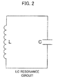
- FIG. 2 is an equivalent circuit diagram illustrating an example of the resonance coil according to the first embodiment.
- the resonance coil 110, 210 configures an LC resonance circuit including the inductance L and the capacitance C.
- FIG. 3 illustrates a specific example of the alternating current power source and the frequency changer according to the first embodiment.
- the alternating current power source 130 and the frequency changer 140 include a PLL (Phase Locked Loop) circuit 160.
- PLL Phase Locked Loop
- the PLL circuit 160 has a voltage controlled oscillator (VCO) 161 configured to output an alternating current having an oscillation frequency according to an input voltage, an amplifier 162 configured to amplify an alternating current output from the voltage controlled oscillator 161 and output the amplified current to the coil 120, and a frequency divider 163 configured to frequency-divide an alternating current output from the voltage controlled oscillator 161.
- VCO voltage controlled oscillator
- the PLL circuit 160 has a phase comparator 164 configured to compare the phase of an output signal of the frequency divider 163 with the phase of a reference signal and output a phase difference signal, a filter 165 configured to convert an output signal of the phase comparator 164 into a direct current signal and output the direct current signal to the voltage controlled oscillator 161, and a voltage controller 166 configured to control the voltage of a signal input to the voltage controlled oscillator 161 from the filter 165 based on communication data.
- a phase comparator 164 configured to compare the phase of an output signal of the frequency divider 163 with the phase of a reference signal and output a phase difference signal
- a filter 165 configured to convert an output signal of the phase comparator 164 into a direct current signal and output the direct current signal to the voltage controlled oscillator 161
- a voltage controller 166 configured to control the voltage of a signal input to the voltage controlled oscillator 161 from the filter 165 based on communication data.
- the voltage controller 166 controls the voltage of a signal input to the voltage controlled oscillator 161 based on communication data, and thereby, the oscillation frequency of the alternating current output from the voltage controlled oscillator 161 changes, thus enabling modulation of the alternating current output from the amplifier 162 to the coil 120.
- the voltage controller 166 corresponds to the frequency changer 140 and the voltage controlled oscillator 161, the amplifier 162, the frequency divider 163, the phase comparator 164, and the filter 165 correspond to the alternating current power source 130.
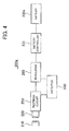
- FIG. 4 illustrates a specific example of the magnetic resonance power receiver according to the first embodiment.
- a magnetic resonance power receiver 200a has the resonance coil 210, the coil 220, a rectifier circuit 250, a regulator 260, a battery controller 231, a battery 230a, and the detector 240.
- the rectifier circuit 250 converts the alternating current generated in the coil 220 into a direct current and outputs the direct current to the regulator 260.
- the regulator 260 makes the direct current input from the rectifier circuit 250 constant and outputs the constant current to the battery controller 231.
- the battery controller 231 accumulates power in the battery 230 by the constant current output from the regulator 260.
- the detector 240 compares the amount of power in accordance with the output current of the rectifier circuit 250 with the reference amount of power generated based on the constant output current of the regulator 260.
- FIG. 5 is a graph illustrating an example of a power transmission state of the magnetic resonance wireless power transmission system according to the first embodiment.
- the horizontal axis of the graph represents the frequency of the alternating current generated by the alternating current power source 130 and the vertical axis represents the transmission power (dB).
- the transmission power is power transmitted from the resonance coil 110 to the resonance coil 210.
- a characteristic 1a represents the transmission power characteristic when the resonance frequency of the resonance coil 110 and the resonance coil 210 is f0.
- the transmission power takes a peak value when the frequency is f0.
- the vicinity of the peak value is distorted, which may be considered to be affected by conditions other than the resonance frequency.
- the transmission power characteristic has a steep characteristic having the value when the frequency is f0 as a peak value.
- the steep characteristic of the transmission power characteristic enables increase of a Q value indicating the efficiency of power transmission.
- the steep characteristic of the transmission power characteristic considerably attenuates the transmission power, if the frequency deviates from f0.
- the transmission power is about 22 dB, when f1, about 15 dB, when f2, about 18 dB, and when f3, about 10 dB.
- the frequency changer 140 modulates the frequency of the alternating current generated by the alternating current power source 130 at the time of communication, the magnitude of power transmitted from the resonance coil 110 changes considerably. Hence, it is made possible to transmit the modulated signal of the amount of power with the large amount of change from the resonance coil 110 to the resonance coil 210.
- FIG. 6 and FIG. 7 are each a timing chart illustrating an example of data transmission of the magnetic resonance wireless power transmission system according to the first embodiment.
- FIG. 6 illustrates the way the frequency of the alternating current generated by the alternating current power source 130, the amount of power detected by the detector 240, and the demodulated data generated by the detector 240 change.
- the resonance frequency of the resonance coil 110 and the resonance coil 210 is f0. It is assumed that the frequencies f0 and f1 correspond to the frequencies f0 and f1 in FIG. 5 .
- the frequency changer 140 changes the frequency of the alternating current generated by the alternating current power source 130 to f0 and f1 based on communication data at the time of communication.
- a reference amount of power Ref is supplied to the detector 240.
- the amount of power detected by the detector 240 is larger than the reference amount of power Ref and the detector 240 generates "0" as demodulated data. Further, when the frequency is f1, the amount of power detected by the detector 240 is smaller than the reference amount of power Ref and the detector 240 generates "1" as modulated data.
- the frequency changer 140 changes the frequency of the alternating current generated by the alternating current power source 130 to f0 and f1 based on communication data, thus enabling the detector 240 to generate 1-bit demodulated data.
- FIG. 7 illustrates the way the frequency of the alternating current generated by the alternating current power source 130, the amount of power detected by the detector 240, and the modulated data generated by the detector 240 change.
- the resonance frequency of the resonance coil 110 and the resonance coil 210 is f0. It is assumed that the frequencies f0, f1, f2, and f3 correspond to the frequencies f0, f1, f2, and f3 in FIG. 5 , respectively.
- the frequency changer 140 changes the frequency of the alternating current generated by the alternating current power source 130 to f0, f1, f2, and f3 based on communication data at the time of communication. Further, to the detector 240, reference amounts of power Ref 1, Ref 2, and Ref 3 are supplied, respectively.
- the amount of power detected by the detector 240 is larger than the reference amount of power Ref 1 and the detector 240 generates "0" as demodulated data.
- the frequency is f1
- the amount of power detected by the detector 240 is between the reference amounts of power Ref 2 and Ref 3 and the detector 240 generates "2" as demodulated data.
- the amount of power detected by the detector 240 is between the reference amounts of power Ref 1 and Ref 2 and the detector 240 generates "1" as demodulated data.
- the frequency is f3
- the amount of power detected by the detector 240 is smaller than the reference amount of power Ref 3 and the detector 240 generates "3" as demodulated data.
- the frequency changer 140 changes the frequency of the alternating current generated by the alternating current power source 130 to f0 to f3 based on communication data as described above, thus enabling the detector 240 to generate 2-bit demodulated data.
- the frequency values changed by the frequency changer 140 are not limited to the four values of f0 to f3 and may be greater.
- the magnetic resonance wireless power transmission system 10 it is made possible to perform data communication using the configuration for performing power transmission by magnetic resonance, that is, the resonance coil 110 and the resonance coil 210 without providing a new communication module. Hence, it is made possible to reduce the costs of the magnetic resonance power transmitter 100 and the magnetic resonance power receiver 200 having the communication function.
- the frequency of the alternating current generated by the alternating current power source 130 is modulated, but it may also be possible to modulate the amplitude of the alternating current generated by the alternating current power source 130 instead.
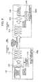
- FIG. 8 illustrates an example of a magnetic resonance wireless power transmission system according to the second embodiment.
- a magnetic resonance wireless power transmission system 10b has a magnetic resonance power transmitter 100b and a magnetic resonance power receiver 200b.
- the magnetic resonance power transmitter 100b is the same as the magnetic resonance power transmitter 100 in the first embodiment except that a coupling changer 170 is provided in place of the frequency changer 140.
- the magnetic resonance power receiver 200b is the same as the magnetic resonance power receiver 200 in the first embodiment.
- the coupling changer 170 changes a coupling state by electromagnetic induction between the resonance coil 110 and the coil 120 based on communication data when the magnetic resonance power transmitter 100b and the magnetic resonance power receiver 200b perform communication.
- the coupling changer 170 changes the coupling state by electromagnetic induction between the resonance coil 110 and the coil 120 based on communication data, thereby enabling modulation of the amount of power transmitted by the resonance coil 110.
- wireless communication of data is performed from the magnetic resonance power transmitter 100b to the magnetic resonance power receiver 200b.
- FIGS. 9A to 9D illustrate an example of a configuration for changing coupling by electromagnetic induction according to the second embodiment.
- FIG. 9A illustrates a configuration in which the distance between the resonance coil 110 and the coil 120 is made variable.
- the coil 120 is provided with a moving mechanism 121 and the coupling changer 170 moves the moving mechanism 121, which makes the distance between the resonance coil 110 and the coil 120 variable.
- the coupling state by electromagnetic induction changes and the amount of power supplied from the coil 120 to the resonance coil 110 changes. For example, when the distance is increased, the amount of power supplied from the coil 120 to the resonance coil 110 is reduced.
- the example illustrated in FIG. 9B has a movable magnetic body 122 inserted between the resonance coil 110 and the coil 120.
- the coupling changer 170 moves the magnetic body 122 to change the arrangement position thereof.
- the coupling state by electromagnetic induction changes and the amount of power supplied from the coil 120 to the resonance coil 110 changes.
- the example illustrated in FIG. 9C has a configuration in which the orientation of the coil 120 with respect to the resonance coil 110 is made variable.
- the coil 120 is provided with a rotating mechanism 123 and rotation of the rotating mechanism 123 by the coupling changer 170 makes variable the angle of the coil 120 with respect to the resonance coil 110.
- the coupling state by electromagnetic induction changes and the amount of power supplied from the coil 120 to the resonance coil 110 changes.
- the example illustrated in FIG. 9D has a variable resistor 124 loaded on the coil 120.
- the coupling state by electromagnetic induction changes and the amount of power supplied from the coil 120 to the resonance coil 110 changes.
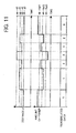
- FIG. 10 and FIG. 11 are each a timing chart illustrating an example of data transmission in the magnetic resonance wireless power transmission system according to the second embodiment.
- FIG. 10 illustrates the way a distance d between the resonance coil 110 and the coil 120, the amount of power detected by the detector 240, and demodulated data generated by the detector 240 change.
- the coupling changer 170 changes the distance d between the resonance coil 110 and the coil 120 to d0 and d1 (d0 ⁇ d1) based on communication data at the time of communication.
- the reference amount of power Ref is supplied to the detector 240.
- the amount of power detected by the detector 240 is larger than the reference amount of power Ref and the detector 240 generates "0" as demodulated data.
- the amount of power detected by the detector 240 is smaller than the reference amount of power Ref and the detector 240 generates "1" as demodulated data.
- the coupling changer 170 changes the distance d between the resonance coil 110 and the coil 120 to d0 and d1 based on communication data, thereby enabling the detector 240 to generate 1-bit demodulated data.
- FIG. 11 illustrates the way the distance d between the resonance coil 110 and the coil 120, the amount of power detected by the detector 240, and the demodulated data generated by the detector 240 change.
- the coupling changer 170 changes the distance d between the resonance coil 110 and the coil 120 to d0, d1, d2, and d3 (d0 ⁇ d1 ⁇ d2 ⁇ d3) based on communication data at the time of communication.
- the reference amounts of power Ref1, Ref2, and Ref3 are supplied.
- the amount of power detected by the detector 240 is larger than the reference amount of power Ref1 and the detector 240 generates "0" as demodulated data.
- the amount of power detected by the detector 240 is between the reference amounts of power Ref2 and Ref3 and the detector 240 generates "2" as demodulated data.
- the amount of power detected by the detector 240 is between the reference amounts of Ref1 and Ref2 and the detector 240 generates "1" as demodulated data.
- the amount of power detected by the detector 240 is smaller than the reference amount of power Ref3 and the detector 240 generates "3" as demodulated data.
- the coupling changer 170 changes the distance d between the resonance coil 110 and the coil 120 to d0 to d3 based on communication data, thereby enabling the detector 240 to generate 2-bit demodulated data.
- the values to which the distance d is changed by the coupling changer 170 are not limited to the four values of d0 to d3 described above and may be greater.
- the magnetic resonance wireless power transmission system 10b it is made possible to perform data communication without providing a new communication module etc., which makes it possible to reduce the costs of the magnetic resonance power transmitter 100b and the magnetic resonance power receiver 200b having the communication function.
- FIG. 12 illustrates an example of a magnetic resonance wireless power transmission system according to the third embodiment.
- a magnetic resonance wireless power transmission system 10c has a magnetic resonance power transmitter 100c and a magnetic resonance power receiver 200c.
- the magnetic resonance power transmitter 100c is the same as the magnetic resonance power transmitter 100 in the first embodiment except that the coupling changer 170 is provided.
- the magnetic resonance power receiver 200c is the same as the magnetic resonance power receiver 200 in the first embodiment.
- FIG. 13 is a timing chart illustrating an example of data transmission of the magnetic resonance wireless power transmission system according to the third embodiment.
- FIG. 13 illustrates the way the frequency of an alternating current generated by the alternating current power source 130, the distance d between the resonance coil 110 and the coil 120, the amount of power detected by the detector 240, and the demodulated data generated by the detector 240 change.
- the coupling changer 170 changes the distance d between the resonance coil 110 and the coil 120 to d0 and d1 (d0 ⁇ d1) based on communication data during a period T1 at the time of communication.
- the frequency changer 140 maintains the frequency of the alternating current generated by the alternating current power source 130 at f0.
- the frequency changer 140 changes the frequency of the alternating current generated by the alternating current power source 130 to f0 and f1 based on communication data.
- the coupling changer 170 maintains the distance d between the resonance coil 110 and the coil 120 at d0
- the amount of power detected by the detector 240 is larger than the reference amount of power Ref and the detector 240 generates "0" as demodulated data.
- the amount of power detected by the detector 240 is smaller than the reference amount of power Ref and the detector 240 generates "1" as demodulated data.
- the amount of power detected by the detector 240 is larger than the reference amount of power Ref and the detector 240 generates "0" as demodulated data.
- the frequency is f1
- the amount of power detected by the detector 240 is smaller than the reference amount of power Ref and the detector 240 generates "1" as demodulated data.
- the first to third embodiments relate to transmission of data from the magnetic resonance power transmitter to the magnetic resonance power receiver, and next, an embodiment relating to transmission of data from a magnetic resonance power receiver to a magnetic resonance power transmitter is explained as a fourth embodiment.
- FIG. 14 illustrates an example of a magnetic resonance wireless power transmission system according to the fourth embodiment.
- a magnetic resonance wireless power transmission system 10d has a magnetic resonance power transmitter 100d and a magnetic resonance power receiver 200d.
- the magnetic resonance power transmitter 100d has the resonance coil 110, the coil 120, the alternating current power source 130, and a detector 180 configured to detect an amount of power generated in the coil 120.
- the magnetic resonance power transmitter 200d has the resonance coil 210, the coil 220, the power receiver 230, and a coupling changer 280.
- the coupling changer 280 changes the coupling state by electromagnetic induction between the resonance coil 210 and the coil 220 based on communication data when the magnetic resonance power transmitter 100d and the magnetic resonance power receiver 200d perform communication.
- the amount of power supplied from the resonance coil 210 to the coil 220 changes. Accordingly, the amount of power transmitted from the resonance coil 110 to the resonance coil 210 changes.
- the coupling changer 280 changes the coupling state by electromagnetic induction between the resonance coil 210 and the coil 220 based on communication data, thereby enabling modulation of the amount of power transmitted from the resonance coil 110 to the resonance coil 210. That is, communication data is transmitted as a modulated signal of the amount of power from the resonance coil 210 to the resonance coil 110.
- the amount of power transmitted from the resonance coil 110 to the resonance coil 210 changes, the amount of power supplied from the coil 120 to the resonance coil 110 also changes and thereby, the amount of power generated in the coil 120 also changes. That is, the modulated signal of the amount of power transmitted to the resonance coil 110 is propagated to the coil 120.
- the detector 180 generates demodulated data including 1-bit data or 2-bit data by detecting the modulated signal of the amount of power propagated to the coil 120 and by comparing the detected modulated signal with the reference amount of power at the time of communication.
- the coupling changer 280 changes the coupling state by electromagnetic induction between the resonance coil 210 and the coil 220 based on communication data, and thus the modulated signal of the amount of power is transmitted from the resonance coil 210 to the resonance coil 110.
- the modulated signal of the amount of power transmitted to the resonance coil 110 is demodulated by the detector 180 and demodulated data is generated. In this manner, wireless communication of data from the magnetic resonance power receiver 200d to the magnetic resonance power transmitter 100d is performed.
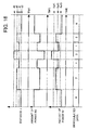
- FIG. 15 and FIG. 16 are each a timing chart illustrating an example of data transmission of the magnetic resonance wireless power transmission system according to the fourth embodiment.
- This timing chart corresponds to the example in which the coupling changer 280 changes the coupling by electromagnetic induction by changing the distance between the resonance coil 210 and the coil 220.
- FIG. 15 illustrates the way the distance d between the resonance coil 210 and the coil 220, an amount of power W2 supplied to the coil 220, an amount of power W1 detected by the detector 180, and the demodulated data generated by the detector 180 change.
- the coupling changer 280 changes the distance d between the resonance coil 210 and the coil 220 to d0 and d1 (d0 ⁇ d1) based on communication data at the time of communication.
- the reference amount of power Ref is supplied to the detector 180.
- the amount of power W1 is smaller than the reference amount of power Ref and the detector 180 generates "0" as demodulated data.
- the amount of power W1 is larger than the reference amount of power Ref and the detector 180 generates "1" as demodulated data.
- the coupling changer 280 changes the distance d between the resonance coil 210 and the coil 220 to d0 and d1 based on communication data, thus enabling the detector 180 to generate 1-bit demodulated data.
- FIG. 16 illustrates the way the distance d between the resonance coil 210 and the coil 220, the amount of power W2 supplied to the coil 220, the amount of power W1 detected by the detector 180, and the demodulated data generated by the detector 180 change.
- the coupling changer 280 changes the distance d between the resonance coil 210 and the coil 220 to d0, d1, d2, and d3 (d0 ⁇ d1 ⁇ d2 ⁇ d3) based on communication data at the time of communication.
- the reference amounts of power Ref1, Ref2, and Ref3 are supplied.
- the amount of power W1 is smaller than the reference amount of power Ref3 and the detector 180 generates "0" as demodulated data.
- the amount of power W1 is between the reference amounts of power Ref1 and Ref2 and the detector 180 generates "2" as demodulated data.
- the amount of power W1 is between the reference amounts of power Ref2 and Ref3 and the detector 180 generates "1" as demodulated data.
- the amount of power W1 is larger than the reference amount of power Ref1 and the detector 180 generates "3" as demodulated data.
- the coupling changer 280 changes the distance d between the resonance coil 210 and the coil 220 to d0 to d3 based on communication data, thus enabling the detector 180 to generate 2-bit demodulated data.
- the values to which the distance d is changed by the coupling changer 280 are not limited to the four values of d0 to d3 described above and may be greater.
- the magnetic resonance wireless power transmission system 10d it is made possible to perform data communication without providing a new communication module etc., which enables reduction of the costs of the magnetic resonance power transmitter 100d and the magnetic resonance power receiver 200d having the communication function.
- FIG. 17 illustrates an example of a magnetic resonance wireless power transmission system according to the fifth embodiment.
- a magnetic resonance wireless power transmission system 10e has a magnetic resonance power transmitter 100e and a magnetic resonance power receiver 200e.
- the magnetic resonance power transmitter 100e is the same as the magnetic resonance power transmitter 100d in the fourth embodiment.
- the magnetic resonance power receiver 200e is the same as the magnetic resonance power receiver 200d in the fourth embodiment except that a resonance frequency changer 270 is provided in place of the coupling changer 280.
- the resonance frequency changer 270 changes the resonance frequency of the resonance coil 210 based on communication data when the magnetic resonance power transmitter 100e and the magnetic resonance power receiver 200e perform communication.
- the resonance frequency of the resonance coil 210 is changed by, for example, changing the capacitance C of the resonance coil 210.
- the resonance frequency of the resonance coil 210 changes, the amount of power transmitted from the resonance coil 110 to the resonance coil 210 also changes.
- the resonance frequency changer 270 changes the resonance frequency of the resonance coil 210 based on communication data, thus enabling modulation of the amount of power transmitted from the resonance coil 110 to the resonance coil 210.
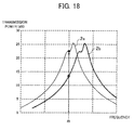
- FIG. 18 is a graph illustrating an example of the power transmission state of the magnetic resonance wireless power transmission system according to the fifth embodiment.
- the horizontal axis of the graph represents the frequency of an alternating current generated by the alternating current power source 130 and the vertical axis, the transmission power (dB).
- a characteristic 2a illustrates the transmission power characteristic when the resonance frequency of the resonance coil 210 agrees with the target frequency f0.
- the transmission power takes a peak value when the frequency is f0.
- the vicinity of the peak value is distorted, which can be considered to be affected by conditions other than the resonance frequency.
- a characteristic 2b illustrates the transmission power characteristic when the resonance frequency of the resonance coil 210 deviates from f0.
- the characteristic 2b is in the state of being shifted in the horizontal axis direction with respect to the characteristic 2a and the transmission power when the frequency is f0 is reduced considerably compared to the transmission power in the case of the characteristic 2a.
- changing the resonance frequency of the resonance coil 210 makes it possible to change the amount of power transmitted from the resonance coil 110 to the resonance coil 210.
- FIG. 19 and FIG. 20 are each a timing chart illustrating an example of data transmission of the magnetic resonance wireless power transmission system according to the fifth embodiment.
- This timing chart corresponds to the example in which the resonance frequency changer 270 changes the capacitance C of the resonance coil 210.
- FIG. 19 illustrates the way the capacitance C of the resonance coil 210, the amount of power W2 supplied to the coil 220, the amount of power W1 detected by the detector 180, and the demodulated data generated by the detector 180 change.
- the resonance frequency changer 270 changes the capacitance C of the resonance coil 210 to c0 and c1 (c0 ⁇ c1) based on communication data at the time of communication.
- the reference amount of power Ref is supplied to the detector 180.
- the capacitance C When the capacitance C is c0, the amount of power W1 is smaller than the reference amount of power Ref and the detector 180 generates "0" as demodulated data. When the capacitance C is c1, the amount of power W1 is larger than the reference amount of power Ref and the detector 180 generates "1" as demodulated data.
- the resonance frequency changer 270 changes the capacitance C of the resonance coil 210 to c0 and c1 based on communication data, thereby enabling the detector 180 to generate 1-bit demodulated data.
- FIG. 20 illustrates the way the capacitance C of the resonance coil 210, the amount of power W2 supplied to the coil 220, the amount of power W1 detected by the detector 180, and the demodulated data generated by the detector 180 change.
- the resonance frequency changer 270 changes the capacitance C of the resonance coil 210 to c0, c1, c2, and c3 (c0 ⁇ c1 ⁇ c2 ⁇ c3) based on communication data at the time of communication.
- the reference amounts of power Ref1, Ref2, and Ref 3 are supplied.
- the amount of power W1 is smaller than the reference amount of power Ref3 and the detector 180 generates "0" as demodulated data.
- the amount of power W1 is between the reference amounts of power Ref1 and Ref2 and the detector 180 generates "2" as demodulated data.
- the amount of power W1 is between the reference amounts of power Ref2 and Ref3 and the detector 180 generates "1" as demodulated data.
- the amount of power W1 is larger than the reference amount of power Ref1 and the detector 180 generates "3" as demodulated data.
- the resonance frequency changer 270 changes the capacitance C of the resonance coil 210 to c0 to c3 based on communication data, thereby enabling the detector 180 to generate 2-bit demodulated data.
- the values to which the capacitance C is changed by the resonance frequency changer 270 are not limited to the four values of c0 to c3 described above and may be greater.
- the magnetic resonance wireless power transmission system 10e it is made possible to perform data communication without providing a new communication module etc., which makes it possible to reduce the costs of the magnetic resonance power transmitter 100e and the magnetic resonance power receiver 200e having the communication function.
- changing the resonance frequency of the resonance coil 110 makes it possible to modulate the amount of power transmitted from the resonance coil 110 to the resonance coil 210, and also to transmit data from the magnetic resonance power transmitter 100e to the magnetic resonance power receiver 200e.
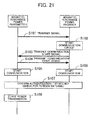
- FIG. 21 is a sequence diagram illustrating an example of a communication procedure of a magnetic resonance wireless power transmission system according to the sixth embodiment.
- the communication method in any of the first to third embodiments is used for transmission of data from the magnetic resonance power transmitter to the magnetic resonance power receiver and the communication method in the fourth or the fifth embodiment is used for transmission of data from the magnetic resonance power receiver to the magnetic resonance power transmitter.
- Step S101 The magnetic resonance power transmitter transmits a signal to the magnetic resonance power receiver.
- Step S102 The magnetic resonance power receiver starts a communication circuit upon receipt of the signal transmitted by the magnetic resonance power transmitter.
- the communication circuit is, for example, the coupling changer 280 when the magnetic resonance power receiver 10d in the fourth embodiment is used as the magnetic resonance power receiver, and when the magnetic resonance power receiver 10e in the fifth embodiment is used, the communication circuit is the resonance frequency changer 270.
- Step 103 The magnetic resonance power receiver transmits a communication start signal to the magnetic resonance power transmitter.
- the magnetic resonance power transmitter transmits the communication start signal to the magnetic resonance power receiver upon receipt of the communication start signal transmitted from the magnetic resonance power receiver.
- Step S105 The magnetic resonance power transmitter starts communication with the magnetic resonance power receiver.
- Step S106 The magnetic resonance power receiver starts communication with the magnetic resonance power transmitter.
- Step S107 The magnetic resonance power transmitter and the magnetic resonance power receiver confirm authentication, transmission efficiency of the amount of power, etc. By confirming the transmission efficiency of the amount of power, it is made possible to check for, for example, the presence/absence of foreign material in the path of power transmission.
- Step S108 The magnetic resonance power transmitter starts power transmission to the magnetic resonance power receiver.
- step S108 may be possible to perform step S108 before step S101. Further, it may also be possible to perform step S108 in parallel with a series of processing of step S101 to step S107.
Landscapes
- Engineering & Computer Science (AREA)
- Computer Networks & Wireless Communication (AREA)
- Power Engineering (AREA)
- Manufacturing & Machinery (AREA)
- Near-Field Transmission Systems (AREA)
Abstract
Description
- The embodiments discussed herein relate to a magnetic resonance power transmitter and a magnetic resonance power receiver used for wireless power transmission by magnetic resonance.
- There exists a magnetic resonance wireless power transmission system that performs wireless power transmission by magnetic resonance. The magnetic resonance wireless power transmission system has a power transmitter including a resonance coil and a power receiver including a resonance coil, and the resonance coil included in the power transmitter and the resonance coil included in the power receiver have the same resonance frequency.
- When power is supplied to the resonance coil of the power transmitter and an alternating current having the same frequency as the resonance frequency of the resonance coil is caused to flow, power is transmitted by magnetic resonance between the resonance coil of the power transmitter and the resonance coil of the power receiver and an alternating current flows through the resonance coil of the power receiver. In this manner, power is transmitted from the power transmitter to the power receiver wirelessly.
- As the wireless power transmission system, there exist, for example, a wireless power transmission system using electric waves and a wireless power transmission system using electromagnetic induction in addition to the magnetic resonance wireless power transmission system. Compared to those other power transmission systems, the magnetic resonance wireless power transmission system has, for example, the following merits. It is possible for the magnetic resonance wireless power transmission system to transmit large power compared to the wireless power transmission system using electric waves. Further, it is possible for the magnetic resonance wireless power transmission system to extend the power transmission distance compared to the wireless power transmission system using electromagnetic induction and also possible to downsize each resonance coil of the power transmitter and the power receiver.
- On the other hand, in the wireless power transmission system, it is necessary to perform wireless communication between the power transmitter and the power receiver in order to grasp the transmitted power to determine an electric power rate in accordance with the transmitted power and to prevent power transmission to other than the transmission target by authenticating the power receiver.
- Hence, it is considered to provide a function to perform wireless communication also in the magnetic resonance wireless power transmission system.
- For example, there is a technique to transmit the charge level of a built-in power source of an implantable micro stimulator to outside by non-contact communication (e.g. see PTL 1). Further, there is a technique that uses a magnetic field and resonance for non-contact communication (e.g. see
PTLS 2 to 4). -
- PTL 1: Japanese National Publication of International Patent Application No.
2005-531371 - PTL 2: Japanese National Publication of International Patent Application No.
2008-535611 - PTL 3: Japanese Laid-Open Patent Publication No.
06-54824 - PTL 4: Japanese Examined Patent Application Publication No.
08-29143 - However, if the already existing non-contact communication function is simply added to the magnetic resonance wireless power transmission system, there is a possibility that the costs of the power transmitter and the power receiver increase because it is necessary to newly provide a communication module to the power transmitter and the power receiver.
- In view of the above, it is an object in one aspect of the embodiments to provide a magnetic resonance power transmitter and a magnetic resonance power receiver the costs of which are reduced and which include the communication function.
- In order to achieve the above-mentioned object, such a magnetic resonance power transmitter as follows is provided.
- The magnetic resonance power transmitter includes a resonance coil, an alternating current power source configured to cause the resonance coil to generate an alternating current, and a frequency changer configured to change, based on communication data, a frequency of the alternating current that the alternating current power source causes the resonance coil to generate.
- According to the magnetic resonance power transmitter and the magnetic resonance power receiver disclosed herein, it is made possible to reduce the costs of the magnetic resonance power transmitter and the magnetic resonance power receiver including the communication function.
- The other objects, features, and advantages of the present invention will become apparent from the following detailed description, taken in conjunction with the accompanying drawings, which illustrates preferred embodiments by way of example of the present invention.
-
- [
FIG. 1] FIG. 1 illustrates an example of a magnetic resonance wireless power transmission system according to a first embodiment. - [
FIG. 2] FIG. 2 is an equivalent circuit diagram illustrating an example of a resonance coil according to the first embodiment. - [
FIG. 3] FIG. 3 illustrates a specific example of an alternating current power source and a frequency changer according to the first embodiment. - [
FIG. 4] FIG. 4 illustrates a specific example of a magnetic resonance power receiver according to the first embodiment. - [
FIG. 5] FIG. 5 is a graph illustrating an example of a power transmission state of a magnetic resonance wireless power transmission system according to the first embodiment. - [
FIG. 6] FIG. 6 is a timing chart illustrating an example of data transmission of the magnetic resonance wireless power transmission system according to the first embodiment. - [
FIG. 7] FIG. 7 is a timing chart illustrating an example of data transmission of the magnetic resonance wireless power transmission system according to the first embodiment. - [
FIG. 8] FIG. 8 illustrates an example of a magnetic resonance wireless power transmission system according to a second embodiment. - [
FIG. 9] FIGS. 9A to 9D illustrate an example of a configuration to change coupling by electromagnetic induction according to the second embodiment. - [
FIG. 10] FIG. 10 is a timing chart illustrating an example of data transmission of the magnetic resonance wireless power transmission system according to the second embodiment. - [
FIG. 11] FIG. 11 is a timing chart illustrating an example of data transmission of the magnetic resonance wireless power transmission system according to the second embodiment. - [
FIG. 12] FIG. 12 illustrates an example of a magnetic resonance wireless power transmission system according to a third embodiment. - [
FIG. 13] FIG. 13 is a timing chart illustrating an example of data transmission of the magnetic resonance wireless power transmission system according to the third embodiment. - [
FIG. 14] FIG. 14 illustrates an example of a magnetic resonance wireless power transmission system according to a fourth embodiment. - [
FIG. 15] FIG. 15 is a timing chart illustrating an example of data transmission of the magnetic resonance wireless power transmission system according to the fourth embodiment. - [
FIG. 16] FIG. 16 is a timing chart illustrating an example of data transmission of the magnetic resonance wireless power transmission system according to the fourth embodiment. - [
FIG. 17] FIG. 17 illustrates an example of a magnetic resonance wireless power transmission system according to a fifth embodiment. - [
FIG. 18] FIG. 18 is a graph illustrating an example of a power transmission state of the magnetic resonance wireless power transmission system according to the fifth embodiment. - [
FIG. 19] FIG. 19 is a timing chart illustrating an example of data transmission of the magnetic resonance wireless power transmission system according to the fifth embodiment. - [
FIG. 20] FIG. 20 is a timing chart illustrating an example of data transmission of the magnetic resonance wireless power transmission system according to the fifth embodiment. - [
FIG. 21] FIG. 21 is a sequence diagram illustrating an example of a communication procedure of a magnetic resonance wireless power transmission system according to a sixth embodiment. - Several embodiments will be described below with reference to the accompanying drawings, wherein like reference numerals refer to like elements throughout.
-
FIG. 1 illustrates an example of a magnetic resonance wireless power transmission system according to a first embodiment. - A magnetic resonance wireless
power transmission system 10 includes a magneticresonance power transmitter 100 configured to transmit power and a magneticresonance power receiver 200 configured to receive power transmitted from the magneticresonance power transmitter 100. - The magnetic
resonance power transmitter 100 has aresonance coil 110, acoil 120 configured to supply power to theresonance coil 110 by electromagnetic induction, and an alternatingcurrent power source 130 configured to cause thecoil 120 to generate an alternating current. - As the material of the
resonance coil 110, for example, copper (Cu) is used. As theresonance coil 110, for example, a helical coil having a diameter of 30 cm is used. Theresonance coil 110 configures an LC resonance circuit having an inductance L and a capacitance C and has the resonance frequency same as the transmission frequency. Here, the transmission frequency refers to the frequency of transmission wave used to transmit power from the magneticresonance power transmitter 100 to the magneticresonance power receiver 200. - The resonance frequency of the
resonance coil 110 is, for example, 10 MHz. Further, in theresonance coil 110, the capacitance C is obtained by the floating capacitance of theresonance coil 110, but it may also be possible to obtain the capacitance C by providing a capacitor between coil wires of theresonance coil 110. - When power is supplied from the
coil 120 by electromagnetic induction and an alternating current having the same frequency as the resonance frequency flows, theresonance coil 110 performs wireless power transmission by magnetic resonance toward the magneticresonance power receiver 200. - The alternating
current power source 130 connects with thecoil 120 and causes thecoil 120 to generate an alternating current having the same frequency as the transmission frequency, for example, 10 MHz. - As the material of the
coil 120, for example, copper (Cu) is used. When an alternating current is supplied from the alternatingcurrent power source 130, thecoil 120 supplies power to theresonance coil 110 by electromagnetic induction and causes theresonance coil 110 to generate an alternating current. - Here, the frequency of the alternating current flowing through the
coil 120 agrees with the frequency of the alternating current generated in theresonance coil 110. That is, when an alternating current having the same frequency as the transmission frequency, for example, 10 MHz, is supplied to thecoil 120, an alternating current having the same frequency as the transmission frequency, for example, 10 MHz, flows through theresonance coil 110. - As described above, power is supplied to the
resonance coil 110 not via a wire etc. but by electromagnetic induction. Due to this, it is possible to prevent the resistance of the alternatingcurrent power source 130 and the wire etc. for power supply from being added to theresonance coil 110, thus enabling obtaining of the highprecision resonance coil 110 having the resonance frequency same as the target frequency. - When it is possible to maintain sufficient precision of the resonance frequency of the
resonance coil 110, it may also be possible to supply power directly to theresonance coil 110 from the alternatingcurrent power source 130 by connecting the alternatingcurrent power source 130 to theresonance coil 110. - Further, the magnetic
resonance power transmitter 100 has afrequency changer 140 configured to change the frequency of an alternating current that the alternatingcurrent power source 130 causes thecoil 120 to generate. - The
frequency changer 140 modulates, based on communication data, the frequency of an alternating current generated by the alternatingcurrent power source 130 when the magneticresonance power transmitter 100 and the magneticresonance power receiver 200 communicate with each other. When the frequency of the alternating current generated by the alternatingcurrent power source 130 is modulated as described above, the amount of power transmitted by theresonance coil 110 is modulated accordingly. - That is, communication data is transmitted from the
resonance coil 110 to the magneticresonance power receiver 200 as a modulated signal of the amount of power. Thefrequency changer 140 maintains the frequency of the alternating current generated by the alternatingcurrent power source 130 to the transmission frequency at the time of power transmission. - Next, the magnetic
resonance power receiver 200 is explained. - The magnetic
resonance power receiver 200 has aresonance coil 210 to which power is transmitted from theresonance coil 110 of the magneticresonance power transmitter 100 and acoil 220 to which the power transmitted to theresonance coil 210 is supplied. The distance between theresonance coil 110 and theresonance coil 210 at the time of power transmission is supposed to be, for example, about several tens cm to 2 m. - As the material of the
resonance coil 210, for example, copper (Cu) is used. As theresonance coil 210, for example, a helical coil having a diameter of 30 cm is used. Theresonance coil 210 configures an LC resonance circuit having the inductance L and the capacitance C and has the resonance frequency same as the transmission frequency. That is, the resonance frequency of theresonance coil 210 agrees with the resonance frequency of theresonance coil 110. - The resonance frequency of the
resonance coil 210 is, for example, 10 MHz. In theresonance coil 210, the capacitance C is obtained by the floating capacitance of theresonance coil 210, but it may also be possible to obtain the capacitance C by providing a capacitor between coil wires of theresonance coil 210. - Further, when power is transmitted by magnetic resonance from the
resonance coil 110 of the magneticresonance power transmitter 100 at the time of power transmission, an alternating current having the same frequency as the transmission frequency flows through theresonance coil 210. - Further, to the
resonance coil 210, a modulated signal of the amount of power is transmitted from theresonance coil 110 of the magneticresonance power transmitter 100 at the time of communication and an alternating current in the magnitude according to the modulated signal flows therethrough. That is, the modulated signal of the amount of power is propagated from theresonance coil 110 to theresonance coil 210. - As the material of the
coil 220, for example, copper (Cu) is used. When an alternating current flows through theresonance coil 210, power is supplied by electromagnetic induction to thecoil 220 from theresonance coil 210 and an alternating current is generated. - As described above, the supply of power from the
resonance coil 210 is not via a wire etc. but by electromagnetic induction. Hence, it is possible to prevent resistance from being added to theresonance coil 210, thus enabling obtaining of the highprecision resonance coil 210 having the resonance frequency same as the target frequency. - Further, through the
coil 220, an alternating current in the magnitude according to the modulated signal of the amount of power propagated to theresonance coil 110 flows at the time of communication. That is, the modulated signal of the amount of power is propagated from theresonance coil 110 to thecoil 220. - Furthermore, the magnetic
resonance power receiver 200 has apower receiver 230 configured to receive power supplied to thecoil 220 and adetector 240 configured to detect the magnitude of power supplied to thecoil 220. - In the
power receiver 230, for example, a power consumer or a power accumulator, such as a battery, is used. When it is possible to maintain sufficient precision of the resonance frequency of theresonance coil 210, it may also be possible to connect thepower receiver 230 to theresonance coil 210 so that thepower receiver 230 may receive power directly from theresonance coil 210. - The
detector 240 detects the modulated signal of the amount of power propagated to thecoil 220 at the time of communication and generates demodulated data including, for example, 1-bit data or 2-bit data by comparing the detected modulated signal with a reference amount of power. - As described above, in the magnetic resonance wireless
power transmission system 10, both theresonance coil 110 and theresonance coil 210 have the resonance frequency same as the transmission frequency. Hence, when power is supplied to theresonance coil 110 to cause an alternating current to flow therethrough, power transmission by magnetic resonance is performed between theresonance coil 110 and theresonance coil 210 and an alternating current flows through theresonance coil 210. In this manner, power is transmitted wirelessly from theresonance coil 110 to theresonance coil 210. - Further, in the magnetic resonance wireless
power transmission system 10, thefrequency changer 140 modulates the frequency of the alternating current generated in thecoil 120 based on communication data and thus the modulated signal of the amount of power is transmitted from theresonance coil 110 to theresonance coil 210. The modulated signal of the amount of power transmitted to theresonance coil 210 is demodulated by thedetector 240 and demodulated data is generated. In this manner, wireless communication of data from the magneticresonance power transmitter 100 to the magneticresonance power receiver 200 is performed. -
FIG. 2 is an equivalent circuit diagram illustrating an example of the resonance coil according to the first embodiment. - As illustrated in
FIG. 2 , theresonance coil 
-
FIG. 3 illustrates a specific example of the alternating current power source and the frequency changer according to the first embodiment. - In this example, the alternating
current power source 130 and thefrequency changer 140 include a PLL (Phase Locked Loop)circuit 160. - The
PLL circuit 160 has a voltage controlled oscillator (VCO) 161 configured to output an alternating current having an oscillation frequency according to an input voltage, anamplifier 162 configured to amplify an alternating current output from the voltage controlledoscillator 161 and output the amplified current to thecoil 120, and afrequency divider 163 configured to frequency-divide an alternating current output from the voltage controlledoscillator 161. - Further, the
PLL circuit 160 has aphase comparator 164 configured to compare the phase of an output signal of thefrequency divider 163 with the phase of a reference signal and output a phase difference signal, afilter 165 configured to convert an output signal of thephase comparator 164 into a direct current signal and output the direct current signal to the voltage controlledoscillator 161, and avoltage controller 166 configured to control the voltage of a signal input to the voltage controlledoscillator 161 from thefilter 165 based on communication data. - In the
PLL circuit 160, thevoltage controller 166 controls the voltage of a signal input to the voltage controlledoscillator 161 based on communication data, and thereby, the oscillation frequency of the alternating current output from the voltage controlledoscillator 161 changes, thus enabling modulation of the alternating current output from theamplifier 162 to thecoil 120. - In the
PLL circuit 160, thevoltage controller 166 corresponds to thefrequency changer 140 and the voltage controlledoscillator 161, theamplifier 162, thefrequency divider 163, thephase comparator 164, and thefilter 165 correspond to the alternatingcurrent power source 130. -
FIG. 4 illustrates a specific example of the magnetic resonance power receiver according to the first embodiment. - A magnetic
resonance power receiver 200a has theresonance coil 210, thecoil 220, arectifier circuit 250, aregulator 260, abattery controller 231, abattery 230a, and thedetector 240. - The
rectifier circuit 250 converts the alternating current generated in thecoil 220 into a direct current and outputs the direct current to theregulator 260. Theregulator 260 makes the direct current input from therectifier circuit 250 constant and outputs the constant current to thebattery controller 231. Thebattery controller 231 accumulates power in thebattery 230 by the constant current output from theregulator 260. Thedetector 240 compares the amount of power in accordance with the output current of therectifier circuit 250 with the reference amount of power generated based on the constant output current of theregulator 260. -
FIG. 5 is a graph illustrating an example of a power transmission state of the magnetic resonance wireless power transmission system according to the first embodiment. - The horizontal axis of the graph represents the frequency of the alternating current generated by the alternating
current power source 130 and the vertical axis represents the transmission power (dB). Here, the transmission power is power transmitted from theresonance coil 110 to theresonance coil 210. - A characteristic 1a represents the transmission power characteristic when the resonance frequency of the
resonance coil 110 and theresonance coil 210 is f0. The transmission power takes a peak value when the frequency is f0. In the characteristic 1a, the vicinity of the peak value is distorted, which may be considered to be affected by conditions other than the resonance frequency. - Further, the transmission power characteristic has a steep characteristic having the value when the frequency is f0 as a peak value. The steep characteristic of the transmission power characteristic enables increase of a Q value indicating the efficiency of power transmission.
- Furthermore, the steep characteristic of the transmission power characteristic considerably attenuates the transmission power, if the frequency deviates from f0. For example, when the frequency is f0, the transmission power is about 22 dB, when f1, about 15 dB, when f2, about 18 dB, and when f3, about 10 dB.
- Due to such a characteristic, when the
frequency changer 140 modulates the frequency of the alternating current generated by the alternatingcurrent power source 130 at the time of communication, the magnitude of power transmitted from theresonance coil 110 changes considerably. Hence, it is made possible to transmit the modulated signal of the amount of power with the large amount of change from theresonance coil 110 to theresonance coil 210. -
FIG. 6 andFIG. 7 are each a timing chart illustrating an example of data transmission of the magnetic resonance wireless power transmission system according to the first embodiment. -
FIG. 6 illustrates the way the frequency of the alternating current generated by the alternatingcurrent power source 130, the amount of power detected by thedetector 240, and the demodulated data generated by thedetector 240 change. - Here, the resonance frequency of the
resonance coil 110 and theresonance coil 210 is f0. It is assumed that the frequencies f0 and f1 correspond to the frequencies f0 and f1 inFIG. 5 . - In this example, the
frequency changer 140 changes the frequency of the alternating current generated by the alternatingcurrent power source 130 to f0 and f1 based on communication data at the time of communication. To thedetector 240, a reference amount of power Ref is supplied. - When the frequency is f0, the amount of power detected by the
detector 240 is larger than the reference amount of power Ref and thedetector 240 generates "0" as demodulated data. Further, when the frequency is f1, the amount of power detected by thedetector 240 is smaller than the reference amount of power Ref and thedetector 240 generates "1" as modulated data. - As described above, the
frequency changer 140 changes the frequency of the alternating current generated by the alternatingcurrent power source 130 to f0 and f1 based on communication data, thus enabling thedetector 240 to generate 1-bit demodulated data. -
FIG. 7 illustrates the way the frequency of the alternating current generated by the alternatingcurrent power source 130, the amount of power detected by thedetector 240, and the modulated data generated by thedetector 240 change. - Here, the resonance frequency of the
resonance coil 110 and theresonance coil 210 is f0. It is assumed that the frequencies f0, f1, f2, and f3 correspond to the frequencies f0, f1, f2, and f3 inFIG. 5 , respectively. - In this example, the
frequency changer 140 changes the frequency of the alternating current generated by the alternatingcurrent power source 130 to f0, f1, f2, and f3 based on communication data at the time of communication. Further, to thedetector 240, reference amounts ofpower Ref 1,Ref 2, andRef 3 are supplied, respectively. - When the frequency is f0, the amount of power detected by the
detector 240 is larger than the reference amount ofpower Ref 1 and thedetector 240 generates "0" as demodulated data. When the frequency is f1, the amount of power detected by thedetector 240 is between the reference amounts ofpower Ref 2 andRef 3 and thedetector 240 generates "2" as demodulated data. - When the frequency is f2, the amount of power detected by the
detector 240 is between the reference amounts ofpower Ref 1 andRef 2 and thedetector 240 generates "1" as demodulated data. When the frequency is f3, the amount of power detected by thedetector 240 is smaller than the reference amount ofpower Ref 3 and thedetector 240 generates "3" as demodulated data. - The
frequency changer 140 changes the frequency of the alternating current generated by the alternatingcurrent power source 130 to f0 to f3 based on communication data as described above, thus enabling thedetector 240 to generate 2-bit demodulated data. The frequency values changed by thefrequency changer 140 are not limited to the four values of f0 to f3 and may be greater. - As explained above, in the magnetic resonance wireless
power transmission system 10, it is made possible to perform data communication using the configuration for performing power transmission by magnetic resonance, that is, theresonance coil 110 and theresonance coil 210 without providing a new communication module. Hence, it is made possible to reduce the costs of the magneticresonance power transmitter 100 and the magneticresonance power receiver 200 having the communication function. - In the first embodiment, the frequency of the alternating current generated by the alternating
current power source 130 is modulated, but it may also be possible to modulate the amplitude of the alternating current generated by the alternatingcurrent power source 130 instead. - Next, an embodiment that differs from the first embodiment in the method for modulating communication data is explained as a second embodiment.
-
FIG. 8 illustrates an example of a magnetic resonance wireless power transmission system according to the second embodiment. - A magnetic resonance wireless
power transmission system 10b has a magneticresonance power transmitter 100b and a magneticresonance power receiver 200b. The magneticresonance power transmitter 100b is the same as the magneticresonance power transmitter 100 in the first embodiment except that acoupling changer 170 is provided in place of thefrequency changer 140. The magneticresonance power receiver 200b is the same as the magneticresonance power receiver 200 in the first embodiment. - The
coupling changer 170 changes a coupling state by electromagnetic induction between theresonance coil 110 and thecoil 120 based on communication data when the magneticresonance power transmitter 100b and the magneticresonance power receiver 200b perform communication. - When the coupling state by electromagnetic induction between the
resonance coil 110 and thecoil 120 changes, the amount of power supplied from thecoil 120 to theresonance coil 110 also changes. Consequently, the amount of power transmitted by theresonance coil 110 also changes. - That is, the
coupling changer 170 changes the coupling state by electromagnetic induction between theresonance coil 110 and thecoil 120 based on communication data, thereby enabling modulation of the amount of power transmitted by theresonance coil 110. - In this manner, as in the first embodiment, wireless communication of data is performed from the magnetic
resonance power transmitter 100b to the magneticresonance power receiver 200b. -
FIGS. 9A to 9D illustrate an example of a configuration for changing coupling by electromagnetic induction according to the second embodiment. - The example illustrated in
FIG. 9A illustrates a configuration in which the distance between theresonance coil 110 and thecoil 120 is made variable. In this example, thecoil 120 is provided with a movingmechanism 121 and thecoupling changer 170 moves the movingmechanism 121, which makes the distance between theresonance coil 110 and thecoil 120 variable. When the distance between theresonance coil 110 and thecoil 120 is changed, the coupling state by electromagnetic induction changes and the amount of power supplied from thecoil 120 to theresonance coil 110 changes. For example, when the distance is increased, the amount of power supplied from thecoil 120 to theresonance coil 110 is reduced. - The example illustrated in
FIG. 9B has a movablemagnetic body 122 inserted between theresonance coil 110 and thecoil 120. In this example, thecoupling changer 170 moves themagnetic body 122 to change the arrangement position thereof. When the arrangement position of themagnetic body 122 is changed, the coupling state by electromagnetic induction changes and the amount of power supplied from thecoil 120 to theresonance coil 110 changes. - The example illustrated in
FIG. 9C has a configuration in which the orientation of thecoil 120 with respect to theresonance coil 110 is made variable. In this example, thecoil 120 is provided with arotating mechanism 123 and rotation of therotating mechanism 123 by thecoupling changer 170 makes variable the angle of thecoil 120 with respect to theresonance coil 110. When the angle of thecoil 120 with respect to theresonance coil 110 is changed, the coupling state by electromagnetic induction changes and the amount of power supplied from thecoil 120 to theresonance coil 110 changes. - The example illustrated in
FIG. 9D has avariable resistor 124 loaded on thecoil 120. In this example, when the resistance value of thevariable resistor 124 is changed by thecoupling changer 170, the coupling state by electromagnetic induction changes and the amount of power supplied from thecoil 120 to theresonance coil 110 changes. - In addition to the above, it is also possible to change the coupling state by electromagnetic induction by changing the ratio of the numbers of windings of coil wires between the
resonance coil 110 and the 120 or the ratio of sizes. - Next,
FIG. 10 andFIG. 11 are each a timing chart illustrating an example of data transmission in the magnetic resonance wireless power transmission system according to the second embodiment. - This timing chart corresponds to the example in which when the
coupling changer 170 changes the distance between theresonance coil 110 and thecoil 120 as illustrated inFIG. 9A , coupling by electromagnetic induction is changed. -
FIG. 10 illustrates the way a distance d between theresonance coil 110 and thecoil 120, the amount of power detected by thedetector 240, and demodulated data generated by thedetector 240 change. - In this example, the
coupling changer 170 changes the distance d between theresonance coil 110 and thecoil 120 to d0 and d1 (d0 < d1) based on communication data at the time of communication. To thedetector 240, the reference amount of power Ref is supplied. - When the distance d is d0, the amount of power detected by the
detector 240 is larger than the reference amount of power Ref and thedetector 240 generates "0" as demodulated data. When the distance d is d1, the amount of power detected by thedetector 240 is smaller than the reference amount of power Ref and thedetector 240 generates "1" as demodulated data. - As described above, the
coupling changer 170 changes the distance d between theresonance coil 110 and thecoil 120 to d0 and d1 based on communication data, thereby enabling thedetector 240 to generate 1-bit demodulated data. -
FIG. 11 illustrates the way the distance d between theresonance coil 110 and thecoil 120, the amount of power detected by thedetector 240, and the demodulated data generated by thedetector 240 change. - In this example, the
coupling changer 170 changes the distance d between theresonance coil 110 and thecoil 120 to d0, d1, d2, and d3 (d0 < d1 < d2 < d3) based on communication data at the time of communication. To thedetector 240, the reference amounts of power Ref1, Ref2, and Ref3 are supplied. - When the distance d is d0, the amount of power detected by the
detector 240 is larger than the reference amount of power Ref1 and thedetector 240 generates "0" as demodulated data. When the distance d is d2, the amount of power detected by thedetector 240 is between the reference amounts of power Ref2 and Ref3 and thedetector 240 generates "2" as demodulated data. - When the distance d is d1, the amount of power detected by the
detector 240 is between the reference amounts of Ref1 and Ref2 and thedetector 240 generates "1" as demodulated data. When the distance d is d3, the amount of power detected by thedetector 240 is smaller than the reference amount of power Ref3 and thedetector 240 generates "3" as demodulated data. - As described above, the
coupling changer 170 changes the distance d between theresonance coil 110 and thecoil 120 to d0 to d3 based on communication data, thereby enabling thedetector 240 to generate 2-bit demodulated data. The values to which the distance d is changed by thecoupling changer 170 are not limited to the four values of d0 to d3 described above and may be greater. - As explained above, in the magnetic resonance wireless
power transmission system 10b, it is made possible to perform data communication without providing a new communication module etc., which makes it possible to reduce the costs of the magneticresonance power transmitter 100b and the magneticresonance power receiver 200b having the communication function. - Next, an embodiment that combines the method for modulating communication data in the first embodiment and the method for modulating communication data in the second embodiment is explained as a third embodiment.
-
FIG. 12 illustrates an example of a magnetic resonance wireless power transmission system according to the third embodiment. - A magnetic resonance wireless
power transmission system 10c has a magneticresonance power transmitter 100c and a magneticresonance power receiver 200c. The magneticresonance power transmitter 100c is the same as the magneticresonance power transmitter 100 in the first embodiment except that thecoupling changer 170 is provided. The magneticresonance power receiver 200c is the same as the magneticresonance power receiver 200 in the first embodiment. -
FIG. 13 is a timing chart illustrating an example of data transmission of the magnetic resonance wireless power transmission system according to the third embodiment. -
FIG. 13 illustrates the way the frequency of an alternating current generated by the alternatingcurrent power source 130, the distance d between theresonance coil 110 and thecoil 120, the amount of power detected by thedetector 240, and the demodulated data generated by thedetector 240 change. - In this example, the
coupling changer 170 changes the distance d between theresonance coil 110 and thecoil 120 to d0 and d1 (d0 < d1) based on communication data during a period T1 at the time of communication. During the period T1, thefrequency changer 140 maintains the frequency of the alternating current generated by the alternatingcurrent power source 130 at f0. - Further, during a period T2, the
frequency changer 140 changes the frequency of the alternating current generated by the alternatingcurrent power source 130 to f0 and f1 based on communication data. During the period T2, thecoupling changer 170 maintains the distance d between theresonance coil 110 and thecoil 120 at d0 - During the period T1, when the distance d is d0, the amount of power detected by the
detector 240 is larger than the reference amount of power Ref and thedetector 240 generates "0" as demodulated data. When the distance d is d1, the amount of power detected by thedetector 240 is smaller than the reference amount of power Ref and thedetector 240 generates "1" as demodulated data. - During the period T2, when the frequency is f0, the amount of power detected by the
detector 240 is larger than the reference amount of power Ref and thedetector 240 generates "0" as demodulated data. When the frequency is f1, the amount of power detected by thedetector 240 is smaller than the reference amount of power Ref and thedetector 240 generates "1" as demodulated data. - As described above, it is also possible to communicate data by combining the method for changing the frequency of the alternating current generated by the alternating
current power source 130 and the method for changing the coupling state by electromagnetic induction between theresonance coil 110 and thecoil 120. - The first to third embodiments relate to transmission of data from the magnetic resonance power transmitter to the magnetic resonance power receiver, and next, an embodiment relating to transmission of data from a magnetic resonance power receiver to a magnetic resonance power transmitter is explained as a fourth embodiment.
-
FIG. 14 illustrates an example of a magnetic resonance wireless power transmission system according to the fourth embodiment. - A magnetic resonance wireless
power transmission system 10d has a magneticresonance power transmitter 100d and a magneticresonance power receiver 200d. - The magnetic
resonance power transmitter 100d has theresonance coil 110, thecoil 120, the alternatingcurrent power source 130, and adetector 180 configured to detect an amount of power generated in thecoil 120. - The magnetic
resonance power transmitter 200d has theresonance coil 210, thecoil 220, thepower receiver 230, and acoupling changer 280. - The
coupling changer 280 changes the coupling state by electromagnetic induction between theresonance coil 210 and thecoil 220 based on communication data when the magneticresonance power transmitter 100d and the magneticresonance power receiver 200d perform communication. - As a method for changing the coupling state by electromagnetic induction between the
resonance coil 210 and thecoil 220, for example, it is possible to apply the method explained usingFIGS. 9A to 9D . - When the coupling state by electromagnetic induction between the
resonance coil 210 and thecoil 220 changes, the amount of power supplied from theresonance coil 210 to thecoil 220 changes. Accordingly, the amount of power transmitted from theresonance coil 110 to theresonance coil 210 changes. - That is, the
coupling changer 280 changes the coupling state by electromagnetic induction between theresonance coil 210 and thecoil 220 based on communication data, thereby enabling modulation of the amount of power transmitted from theresonance coil 110 to theresonance coil 210. That is, communication data is transmitted as a modulated signal of the amount of power from theresonance coil 210 to theresonance coil 110. - When the amount of power transmitted from the
resonance coil 110 to theresonance coil 210 changes, the amount of power supplied from thecoil 120 to theresonance coil 110 also changes and thereby, the amount of power generated in thecoil 120 also changes. That is, the modulated signal of the amount of power transmitted to theresonance coil 110 is propagated to thecoil 120. - The
detector 180 generates demodulated data including 1-bit data or 2-bit data by detecting the modulated signal of the amount of power propagated to thecoil 120 and by comparing the detected modulated signal with the reference amount of power at the time of communication. - As described above, in the magnetic resonance wireless
power transmission system 10d, thecoupling changer 280 changes the coupling state by electromagnetic induction between theresonance coil 210 and thecoil 220 based on communication data, and thus the modulated signal of the amount of power is transmitted from theresonance coil 210 to theresonance coil 110. The modulated signal of the amount of power transmitted to theresonance coil 110 is demodulated by thedetector 180 and demodulated data is generated. In this manner, wireless communication of data from the magneticresonance power receiver 200d to the magneticresonance power transmitter 100d is performed. - Next,
FIG. 15 andFIG. 16 are each a timing chart illustrating an example of data transmission of the magnetic resonance wireless power transmission system according to the fourth embodiment. - This timing chart corresponds to the example in which the
coupling changer 280 changes the coupling by electromagnetic induction by changing the distance between theresonance coil 210 and thecoil 220. -
FIG. 15 illustrates the way the distance d between theresonance coil 210 and thecoil 220, an amount of power W2 supplied to thecoil 220, an amount of power W1 detected by thedetector 180, and the demodulated data generated by thedetector 180 change. - In this example, the
coupling changer 280 changes the distance d between theresonance coil 210 and thecoil 220 to d0 and d1 (d0 < d1) based on communication data at the time of communication. To thedetector 180, the reference amount of power Ref is supplied. - When the distance d is d0, the amount of power W1 is smaller than the reference amount of power Ref and the
detector 180 generates "0" as demodulated data. When the distance d is d1, the amount of power W1 is larger than the reference amount of power Ref and thedetector 180 generates "1" as demodulated data. - As described above, the
coupling changer 280 changes the distance d between theresonance coil 210 and thecoil 220 to d0 and d1 based on communication data, thus enabling thedetector 180 to generate 1-bit demodulated data. -
FIG. 16 illustrates the way the distance d between theresonance coil 210 and thecoil 220, the amount of power W2 supplied to thecoil 220, the amount of power W1 detected by thedetector 180, and the demodulated data generated by thedetector 180 change. - In this example, the
coupling changer 280 changes the distance d between theresonance coil 210 and thecoil 220 to d0, d1, d2, and d3 (d0 < d1 < d2 < d3) based on communication data at the time of communication. To thedetector 180, the reference amounts of power Ref1, Ref2, and Ref3 are supplied. - When the distance d is d0, the amount of power W1 is smaller than the reference amount of power Ref3 and the
detector 180 generates "0" as demodulated data. When the distance d is d2, the amount of power W1 is between the reference amounts of power Ref1 and Ref2 and thedetector 180 generates "2" as demodulated data. - When the distance d is d1, the amount of power W1 is between the reference amounts of power Ref2 and Ref3 and the
detector 180 generates "1" as demodulated data. When the distance d is d3, the amount of power W1 is larger than the reference amount of power Ref1 and thedetector 180 generates "3" as demodulated data. - As described above, the
coupling changer 280 changes the distance d between theresonance coil 210 and thecoil 220 to d0 to d3 based on communication data, thus enabling thedetector 180 to generate 2-bit demodulated data. The values to which the distance d is changed by thecoupling changer 280 are not limited to the four values of d0 to d3 described above and may be greater. - As explained above, in the magnetic resonance wireless
power transmission system 10d, it is made possible to perform data communication without providing a new communication module etc., which enables reduction of the costs of the magneticresonance power transmitter 100d and the magneticresonance power receiver 200d having the communication function. - Next, an embodiment that differs from the fourth embodiment in the method for modulating communication data is explained as a fifth embodiment.
-
FIG. 17 illustrates an example of a magnetic resonance wireless power transmission system according to the fifth embodiment. - A magnetic resonance wireless
power transmission system 10e has a magneticresonance power transmitter 100e and a magneticresonance power receiver 200e. The magneticresonance power transmitter 100e is the same as the magneticresonance power transmitter 100d in the fourth embodiment. The magneticresonance power receiver 200e is the same as the magneticresonance power receiver 200d in the fourth embodiment except that aresonance frequency changer 270 is provided in place of thecoupling changer 280. - The
resonance frequency changer 270 changes the resonance frequency of theresonance coil 210 based on communication data when the magneticresonance power transmitter 100e and the magneticresonance power receiver 200e perform communication. The resonance frequency of theresonance coil 210 is changed by, for example, changing the capacitance C of theresonance coil 210. - When the resonance frequency of the
resonance coil 210 changes, the amount of power transmitted from theresonance coil 110 to theresonance coil 210 also changes. - That is, the
resonance frequency changer 270 changes the resonance frequency of theresonance coil 210 based on communication data, thus enabling modulation of the amount of power transmitted from theresonance coil 110 to theresonance coil 210. - In this manner, as in the fourth embodiment, wireless communication of data from the magnetic
resonance power receiver 200e to the magneticresonance power transmitter 100e is performed. -
FIG. 18 is a graph illustrating an example of the power transmission state of the magnetic resonance wireless power transmission system according to the fifth embodiment. - The horizontal axis of the graph represents the frequency of an alternating current generated by the alternating
current power source 130 and the vertical axis, the transmission power (dB). - A characteristic 2a illustrates the transmission power characteristic when the resonance frequency of the
resonance coil 210 agrees with the target frequency f0. In the characteristic 2a, the transmission power takes a peak value when the frequency is f0. In the characteristic 2a, the vicinity of the peak value is distorted, which can be considered to be affected by conditions other than the resonance frequency. - A characteristic 2b illustrates the transmission power characteristic when the resonance frequency of the
resonance coil 210 deviates from f0. The characteristic 2b is in the state of being shifted in the horizontal axis direction with respect to the characteristic 2a and the transmission power when the frequency is f0 is reduced considerably compared to the transmission power in the case of the characteristic 2a. - As described above, changing the resonance frequency of the
resonance coil 210 makes it possible to change the amount of power transmitted from theresonance coil 110 to theresonance coil 210. - Next,
FIG. 19 andFIG. 20 are each a timing chart illustrating an example of data transmission of the magnetic resonance wireless power transmission system according to the fifth embodiment. - This timing chart corresponds to the example in which the
resonance frequency changer 270 changes the capacitance C of theresonance coil 210. -
FIG. 19 illustrates the way the capacitance C of theresonance coil 210, the amount of power W2 supplied to thecoil 220, the amount of power W1 detected by thedetector 180, and the demodulated data generated by thedetector 180 change. - In this example, the
resonance frequency changer 270 changes the capacitance C of theresonance coil 210 to c0 and c1 (c0 < c1) based on communication data at the time of communication. To thedetector 180, the reference amount of power Ref is supplied. - When the capacitance C is c0, the amount of power W1 is smaller than the reference amount of power Ref and the
detector 180 generates "0" as demodulated data. When the capacitance C is c1, the amount of power W1 is larger than the reference amount of power Ref and thedetector 180 generates "1" as demodulated data. - As described above, the
resonance frequency changer 270 changes the capacitance C of theresonance coil 210 to c0 and c1 based on communication data, thereby enabling thedetector 180 to generate 1-bit demodulated data. -
FIG. 20 illustrates the way the capacitance C of theresonance coil 210, the amount of power W2 supplied to thecoil 220, the amount of power W1 detected by thedetector 180, and the demodulated data generated by thedetector 180 change. - In this example, the
resonance frequency changer 270 changes the capacitance C of theresonance coil 210 to c0, c1, c2, and c3 (c0 < c1 < c2 < c3) based on communication data at the time of communication. To thedetector 180, the reference amounts of power Ref1, Ref2, andRef 3 are supplied. - When the capacitance C is c0, the amount of power W1 is smaller than the reference amount of power Ref3 and the
detector 180 generates "0" as demodulated data. When the capacitance C is c2, the amount of power W1 is between the reference amounts of power Ref1 and Ref2 and thedetector 180 generates "2" as demodulated data. - When the capacitance C is c1, the amount of power W1 is between the reference amounts of power Ref2 and Ref3 and the
detector 180 generates "1" as demodulated data. When the capacitance C is c3, the amount of power W1 is larger than the reference amount of power Ref1 and thedetector 180 generates "3" as demodulated data. - As described above, the
resonance frequency changer 270 changes the capacitance C of theresonance coil 210 to c0 to c3 based on communication data, thereby enabling thedetector 180 to generate 2-bit demodulated data. The values to which the capacitance C is changed by theresonance frequency changer 270 are not limited to the four values of c0 to c3 described above and may be greater. - As explained above, in the magnetic resonance wireless
power transmission system 10e, it is made possible to perform data communication without providing a new communication module etc., which makes it possible to reduce the costs of the magneticresonance power transmitter 100e and the magneticresonance power receiver 200e having the communication function. - It is also possible to apply the method for transmitting data from the magnetic
resonance power receiver 200e to the magneticresonance power transmitter 100e in the fifth embodiment to the method for transmitting data from the magneticresonance power transmitter 100e to the magneticresonance power receiver 200e. - That is, changing the resonance frequency of the
resonance coil 110 makes it possible to modulate the amount of power transmitted from theresonance coil 110 to theresonance coil 210, and also to transmit data from the magneticresonance power transmitter 100e to the magneticresonance power receiver 200e. - Next, a communication procedure of a magnetic resonance power transmitter and a magnetic resonance power receiver in a magnetic resonance wireless power transmission system is explained as a sixth embodiment.
-
FIG. 21 is a sequence diagram illustrating an example of a communication procedure of a magnetic resonance wireless power transmission system according to the sixth embodiment. - In the sixth embodiment, it is assumed that the communication method in any of the first to third embodiments is used for transmission of data from the magnetic resonance power transmitter to the magnetic resonance power receiver and the communication method in the fourth or the fifth embodiment is used for transmission of data from the magnetic resonance power receiver to the magnetic resonance power transmitter.
- (Step S101) The magnetic resonance power transmitter transmits a signal to the magnetic resonance power receiver.
- (Step S102) The magnetic resonance power receiver starts a communication circuit upon receipt of the signal transmitted by the magnetic resonance power transmitter. Here, the communication circuit is, for example, the
coupling changer 280 when the magneticresonance power receiver 10d in the fourth embodiment is used as the magnetic resonance power receiver, and when the magneticresonance power receiver 10e in the fifth embodiment is used, the communication circuit is theresonance frequency changer 270. - (Step 103) The magnetic resonance power receiver transmits a communication start signal to the magnetic resonance power transmitter.
- (Step 104) The magnetic resonance power transmitter transmits the communication start signal to the magnetic resonance power receiver upon receipt of the communication start signal transmitted from the magnetic resonance power receiver.
- (Step S105) The magnetic resonance power transmitter starts communication with the magnetic resonance power receiver.
- (Step S106) The magnetic resonance power receiver starts communication with the magnetic resonance power transmitter.
- (Step S107) The magnetic resonance power transmitter and the magnetic resonance power receiver confirm authentication, transmission efficiency of the amount of power, etc. By confirming the transmission efficiency of the amount of power, it is made possible to check for, for example, the presence/absence of foreign material in the path of power transmission.
- (Step S108) The magnetic resonance power transmitter starts power transmission to the magnetic resonance power receiver.
- It may be possible to perform step S108 before step S101. Further, it may also be possible to perform step S108 in parallel with a series of processing of step S101 to step S107.
- The foregoing is considered as illustrative only of the principles of the present invention. Further, since numerous modifications and changes will readily occur to those skilled in the art, it is not desired to limit the invention to the exact construction and applications shown and described, and accordingly, all suitable modifications and equivalents may be regarded as falling within the scope of the invention in the appended claims and their equivalents.
-
- 10
- magnetic resonance wireless power transmission system
- 100
- magnetic resonance power transmitter
- 110, 210
- resonance coil
- 120, 220
- coil
- 130
- alternating current power source
- 140
- frequency changer
- 200
- magnetic resonance power receiver
- 230
- power receiver
- 240
- detector
Claims (10)
- A magnetic resonance power transmitter comprising:a resonance coil;an alternating current power source configured to cause the resonance coil to generate an alternating current; anda frequency changer configured to change, based on communication data, a frequency of the alternating current that the alternating current power source causes the resonance coil to generate.
- A magnetic resonance power transmitter comprising:a resonance coil;a coil configured to cause the resonance coil to generate an alternating current by electromagnetic induction;an alternating current power source configured to cause the coil to generate an alternating current; anda coupling changer configured to change, based on communication data, a coupling state by electromagnetic induction between the resonance coil and the coil.
- The magnetic resonance power transmitter according to claim 2,
wherein the coupling changer changes the coupling state by changing a distance between the resonance coil and the coil. - The magnetic resonance power transmitter according to claim 2,
wherein the coupling changer changes the coupling state by arranging a magnetic body between the resonance coil and the coil. - The magnetic resonance power transmitter according to claim 2,
wherein the coupling changer changes the coupling state by changing an angle of the resonance coil or the coil. - The magnetic resonance power transmitter according to claim 2,
wherein the coupling changer changes the coupling state by changing a load resistance of the resonance coil or the coil. - A magnetic resonance power receiver comprising:a resonance coil;a coil to which power is supplied by electromagnetic induction from the resonance coil;a power receiver configured to receive power supplied to the coil; anda coupling changer configured to change, based on communication data, a coupling state by electromagnetic induction between the resonance coil and the coil.
- The magnetic resonance power receiver according to claim 7,
wherein the coupling changer changes the coupling state by changing a distance between the resonance coil and the coil. - A magnetic resonance power receiver comprising:a resonance coil;a coil to which power is supplied by electromagnetic induction from the resonance coil;a power receiver configured to receive power supplied to the coil; anda resonance frequency changer configured to change a resonance frequency of the resonance coil based on communication data.
- The magnetic resonance power receiver according to claim 9,
wherein the resonance frequency changer changes the resonance frequency by changing a capacitance of the resonance coil.
Applications Claiming Priority (1)
| Application Number | Priority Date | Filing Date | Title |
|---|---|---|---|
| PCT/JP2009/070953 WO2011074082A1 (en) | 2009-12-16 | 2009-12-16 | Magnetic-resonant-coupling power transmission apparatus and magnetic-resonant-coupling power reception apparatus |
Publications (2)
| Publication Number | Publication Date |
|---|---|
| EP2515415A1 true EP2515415A1 (en) | 2012-10-24 |
| EP2515415A4 EP2515415A4 (en) | 2016-11-09 |
Family
ID=44166877
Family Applications (1)
| Application Number | Title | Priority Date | Filing Date |
|---|---|---|---|
| EP09852275.8A Withdrawn EP2515415A4 (en) | 2009-12-16 | 2009-12-16 | RESONANT MAGNETIC COUPLING ENERGY EMISSION APPARATUS AND RESONANT MAGNETIC COUPLING ENERGY RECEPTION APPARATUS |
Country Status (6)
| Country | Link |
|---|---|
| US (1) | US9450455B2 (en) |
| EP (1) | EP2515415A4 (en) |
| JP (1) | JP5505425B2 (en) |
| KR (1) | KR101383383B1 (en) |
| CN (1) | CN102668323B (en) |
| WO (1) | WO2011074082A1 (en) |
Cited By (1)
| Publication number | Priority date | Publication date | Assignee | Title |
|---|---|---|---|---|
| US9912169B2 (en) | 2012-11-06 | 2018-03-06 | Ihi Corporation | Wireless power supply system |
Families Citing this family (50)
| Publication number | Priority date | Publication date | Assignee | Title |
|---|---|---|---|---|
| KR102020869B1 (en) | 2011-08-24 | 2019-09-11 | 삼성전자주식회사 | Communication system using wireless power |
| JP5737410B2 (en) * | 2011-09-02 | 2015-06-17 | 富士通株式会社 | Power repeater |
| WO2013031025A1 (en) | 2011-09-02 | 2013-03-07 | 富士通株式会社 | Power relay |
| JP5667019B2 (en) * | 2011-09-14 | 2015-02-12 | 株式会社東芝 | Wireless power transmission apparatus and method |
| JP5665710B2 (en) * | 2011-09-26 | 2015-02-04 | 株式会社東芝 | Wireless power transmission system, power transmission device and power reception device |
| JP6016596B2 (en) * | 2011-12-07 | 2016-10-26 | 株式会社半導体エネルギー研究所 | Contactless power supply system |
| US9847675B2 (en) * | 2011-12-16 | 2017-12-19 | Semiconductor Energy Laboratory Co., Ltd. | Power receiving device and power feeding system |
| WO2013114576A1 (en) | 2012-01-31 | 2013-08-08 | 富士通株式会社 | Power transmission device, power transmission system, and power transmission method |
| US8933589B2 (en) | 2012-02-07 | 2015-01-13 | The Gillette Company | Wireless power transfer using separately tunable resonators |
| US9412513B2 (en) * | 2012-03-30 | 2016-08-09 | Tdk Corporation | Wireless power transmission system |
| WO2013153736A1 (en) * | 2012-04-10 | 2013-10-17 | パナソニック株式会社 | Wireless power transmitting apparatus, power transmitting apparatus, and power receiving apparatus |
| US9275791B2 (en) * | 2012-08-31 | 2016-03-01 | Qualcomm Incorporated | Systems and methods for decoupling multiple wireless charging transmitters |
| CN109067014B (en) | 2012-09-05 | 2022-04-15 | 瑞萨电子株式会社 | Non-contact charging device |
| EP2985874B1 (en) * | 2013-03-29 | 2017-06-14 | Nissan Motor Co., Ltd | Non-contact power supply system |
| JP2014204452A (en) * | 2013-04-01 | 2014-10-27 | 日東電工株式会社 | Power reception apparatus |
| CN104242477A (en) * | 2013-06-24 | 2014-12-24 | 海尔集团技术研发中心 | Wireless electric energy transmission system with impurity detection function and impurity detection method |
| KR102125917B1 (en) * | 2013-08-07 | 2020-07-08 | 엘지이노텍 주식회사 | Wireless power transmitting device |
| CN103390925A (en) * | 2013-08-12 | 2013-11-13 | 苏州启智机电技术有限公司 | Resonant type electronic charger |
| WO2015046639A1 (en) * | 2013-09-25 | 2015-04-02 | Korea Electronics Technology Institute | In-band control protocole for wireless power transfer |
| WO2015046640A1 (en) * | 2013-09-25 | 2015-04-02 | Korea Electronics Technology Institute | Management protocol of wireless power transfer for multi-devices |
| EP3089320A4 (en) * | 2013-12-10 | 2016-12-28 | Chugoku Electric Power | Power-transmitting device and power-feeding system |
| JP6392550B2 (en) * | 2014-02-10 | 2018-09-19 | ローム株式会社 | Wireless power receiving apparatus and control circuit thereof, electronic device using the same, and abnormality detection method |
| US10084343B2 (en) | 2014-06-13 | 2018-09-25 | Empire Technology Development Llc | Frequency changing encoded resonant power transfer |
| US10320228B2 (en) | 2014-09-08 | 2019-06-11 | Empire Technology Development Llc | Power coupling device |
| US10069324B2 (en) | 2014-09-08 | 2018-09-04 | Empire Technology Development Llc | Systems and methods for coupling power to devices |
| DE102014118040B4 (en) * | 2014-12-05 | 2017-08-24 | Fraunhofer-Gesellschaft zur Förderung der angewandten Forschung e.V. | Control circuit for a base station for transmitting energy to a receiver by means of an electrical resonant circuit, evaluation device, method and computer program |
| KR20160142927A (en) * | 2015-06-03 | 2016-12-14 | 인천대학교 산학협력단 | Wireless Power Charging Apparatus and Method for Mobile |
| EP3299805A4 (en) * | 2015-06-25 | 2018-12-26 | Sintokogio, Ltd. | Surface characteristic evaluation apparatus and surface characteristic evaluation method for steel material |
| KR102496942B1 (en) * | 2015-08-24 | 2023-02-06 | 더 리젠츠 오브 더 유니버시티 오브 캘리포니아 | Low Power Magnetic Field Body Area Networks |
| USD876628S1 (en) | 2016-07-20 | 2020-02-25 | Nyxoah S.A. | Medical implant |
| USD988519S1 (en) | 2016-09-12 | 2023-06-06 | Nyxoah S.A. | Patch |
| FR3060234B1 (en) * | 2016-12-13 | 2019-05-10 | Continental Automotive France | METHOD OF CHARGING A MOBILE TERMINAL BY A MOBILE DEVICE FOR ONBOARDING ON A MOTOR VEHICLE AND RELATED CHARGING DEVICE |
| US11707623B2 (en) | 2017-02-28 | 2023-07-25 | Nyxoah S.A. | Surgical implant system |
| JP7187439B2 (en) * | 2017-03-28 | 2022-12-12 | ソニーセミコンダクタソリューションズ株式会社 | Signal processing apparatus and method |
| JP6377801B2 (en) * | 2017-05-02 | 2018-08-22 | 京セラ株式会社 | Power transmission device and wireless power transmission system |
| WO2020204944A1 (en) * | 2019-04-05 | 2020-10-08 | Halliburton Energy Services, Inc. | Reverse circular polarization based antenna orientation |
| NO20211061A1 (en) | 2019-04-05 | 2021-09-03 | Halliburton Energy Services Inc | Circular polarization correction in nuclear magnetic resonsance (NMR) logging |
| WO2021059285A1 (en) * | 2019-09-26 | 2021-04-01 | Soreq Nuclear Research Center | Wireless enhanced power transfer |
| US10892800B1 (en) | 2020-01-06 | 2021-01-12 | Nucurrent, Inc. | Systems and methods for wireless power transfer including pulse width encoded data communications |
| US11303164B2 (en) | 2020-07-24 | 2022-04-12 | Nucurrent, Inc. | Low cost communications demodulation for wireless power transmission system |
| US11303165B2 (en) | 2020-07-24 | 2022-04-12 | Nucurrent, Inc. | Low cost communications demodulation for wireless power receiver system |
| WO2022020581A1 (en) * | 2020-07-24 | 2022-01-27 | Nucurrent, Inc. | Low cost communications demodulation for wireless power transfer system |
| US11277034B1 (en) | 2021-02-01 | 2022-03-15 | Nucurrent, Inc. | Systems and methods for receiver beaconing in wireless power systems |
| US11811244B2 (en) | 2021-02-01 | 2023-11-07 | Nucurrent, Inc. | Automatic gain control for communications demodulation in wireless power transmitters |
| US11569694B2 (en) | 2021-02-01 | 2023-01-31 | Nucurrent, Inc. | Automatic gain control for communications demodulation in wireless power receivers |
| US11431205B2 (en) | 2021-02-01 | 2022-08-30 | Nucurrent, Inc. | Systems and methods for receiver beaconing in wireless power systems |
| US11277031B1 (en) | 2021-02-01 | 2022-03-15 | Nucurrent, Inc. | Automatic gain control for communications demodulation in wireless power transmitters |
| US11277035B1 (en) | 2021-02-01 | 2022-03-15 | Nucurrent, Inc. | Automatic gain control for communications demodulation in wireless power transmitters |
| US11431204B2 (en) | 2021-02-01 | 2022-08-30 | Nucurrent, Inc. | Automatic gain control for communications demodulation in wireless power transfer systems |
| CN114243934A (en) * | 2021-12-14 | 2022-03-25 | 东莞市力博得电子科技有限公司 | Wireless charging communication method and device |
Family Cites Families (34)
| Publication number | Priority date | Publication date | Assignee | Title |
|---|---|---|---|---|
| JPH0829143B2 (en) | 1986-04-30 | 1996-03-27 | 株式会社島津製作所 | High frequency excitation coil tuning measurement method for MRI apparatus |
| JPH0278347A (en) * | 1988-09-14 | 1990-03-19 | Nippon Signal Co Ltd:The | Transmitter between equipment on ground and on vehicle |
| FR2665265B1 (en) | 1990-07-25 | 1993-04-16 | Magnetech Sa | WIRELESS RECEPTION DEVICE FOR NUCLEAR MAGNETIC RESONANCE IMAGING APPARATUS. |
| JP2879285B2 (en) * | 1993-02-19 | 1999-04-05 | 富士通電装株式会社 | Communication control method for electric vehicles |
| JPH0829143A (en) | 1994-07-13 | 1996-02-02 | Mazda Motor Corp | Surface condition inspection method and apparatus |
| US5760584A (en) | 1996-08-16 | 1998-06-02 | General Electric Company | Shield for MR system RF coil provided with multiple capacitive channels for RF current flow |
| JP3692541B2 (en) | 1997-02-03 | 2005-09-07 | ソニー株式会社 | Power transmission device and power transmission method |
| JP3629176B2 (en) * | 2000-02-09 | 2005-03-16 | 株式会社東芝 | Portable wireless terminal |
| WO2003002950A1 (en) * | 2001-06-27 | 2003-01-09 | Fraunhofer-Gesellschaft zur Förderung der angewandten Forschung e. V. | Method and device for preparing a sensor signal of a position sensor for transmission to an evaluation unit |
| US8386048B2 (en) | 2002-06-28 | 2013-02-26 | Boston Scientific Neuromodulation Corporation | Systems and methods for communicating with or providing power to an implantable stimulator |
| US7428438B2 (en) | 2002-06-28 | 2008-09-23 | Boston Scientific Neuromodulation Corporation | Systems and methods for providing power to a battery in an implantable stimulator |
| US7437193B2 (en) | 2002-06-28 | 2008-10-14 | Boston Scientific Neuromodulation Corporation | Microstimulator employing improved recharging reporting and telemetry techniques |
| US7822480B2 (en) | 2002-06-28 | 2010-10-26 | Boston Scientific Neuromodulation Corporation | Systems and methods for communicating with an implantable stimulator |
| JP4217106B2 (en) | 2003-05-23 | 2009-01-28 | パナソニック株式会社 | Monolithic microwave integrated circuit |
| KR20040072581A (en) | 2004-07-29 | 2004-08-18 | (주)제이씨 프로텍 | An amplification relay device of electromagnetic wave and a radio electric power conversion apparatus using the above device |
| DE602006013302D1 (en) | 2005-04-15 | 2010-05-12 | Koninkl Philips Electronics Nv | ANTENNA DEVICE FOR RECEIVING MAGNETIC RESONANCE SIGNALS WITH ASSOCIATED COMMUNICATION UNIT |
| KR101118710B1 (en) | 2005-07-12 | 2012-03-13 | 메사추세츠 인스티튜트 오브 테크놀로지 | Wireless non-radiative energy transfer |
| US7825543B2 (en) | 2005-07-12 | 2010-11-02 | Massachusetts Institute Of Technology | Wireless energy transfer |
| JP2008178195A (en) * | 2007-01-17 | 2008-07-31 | Seiko Epson Corp | Power transmission control device, power reception control device, non-contact power transmission system, power transmission device, power reception device, and electronic device |
| JP4413236B2 (en) * | 2007-02-16 | 2010-02-10 | セイコーエプソン株式会社 | Power reception control device, power transmission control device, non-contact power transmission system, power reception device, power transmission device, and electronic device |
| JP4649430B2 (en) | 2007-03-20 | 2011-03-09 | セイコーエプソン株式会社 | Non-contact power transmission device |
| CN101330229A (en) * | 2007-06-21 | 2008-12-24 | 北京市北邮信息科技发展有限责任公司 | Non-contact type apparatus for transmitting electric energy |
| JP2010539885A (en) * | 2007-09-17 | 2010-12-16 | クゥアルコム・インコーポレイテッド | High efficiency and high power transmission in wireless power magnetic resonator |
| JP4453741B2 (en) * | 2007-10-25 | 2010-04-21 | トヨタ自動車株式会社 | Electric vehicle and vehicle power supply device |
| JP4974171B2 (en) * | 2007-12-07 | 2012-07-11 | ソニーモバイルコミュニケーションズ株式会社 | Non-contact wireless communication device, method for adjusting resonance frequency of non-contact wireless communication antenna, and portable terminal device |
| US8855554B2 (en) * | 2008-03-05 | 2014-10-07 | Qualcomm Incorporated | Packaging and details of a wireless power device |
| JP2009253762A (en) * | 2008-04-08 | 2009-10-29 | Sony Corp | Radio communication device, wireless communication system, radio communication method and program |
| JP4572949B2 (en) * | 2008-04-08 | 2010-11-04 | ソニー株式会社 | Wireless communication apparatus, wireless communication system, wireless communication method, and program |
| JP4911148B2 (en) * | 2008-09-02 | 2012-04-04 | ソニー株式会社 | Contactless power supply |
| JP5238420B2 (en) * | 2008-09-11 | 2013-07-17 | 矢崎総業株式会社 | Wireless charging system for vehicles |
| JP2010068634A (en) * | 2008-09-11 | 2010-03-25 | Yazaki Corp | Wireless charging system for vehicle |
| JP5308127B2 (en) * | 2008-11-17 | 2013-10-09 | 株式会社豊田中央研究所 | Power supply system |
| JP5324901B2 (en) * | 2008-12-09 | 2013-10-23 | 日立コンシューマエレクトロニクス株式会社 | Non-contact power transmission system |
| EP2416470B1 (en) | 2009-03-30 | 2019-11-13 | Fujitsu Limited | Wireless power supply system, wireless power transmission device, and wireless power receiving device |
-
2009
- 2009-12-16 EP EP09852275.8A patent/EP2515415A4/en not_active Withdrawn
- 2009-12-16 WO PCT/JP2009/070953 patent/WO2011074082A1/en not_active Ceased
- 2009-12-16 CN CN200980162438.7A patent/CN102668323B/en not_active Expired - Fee Related
- 2009-12-16 KR KR1020127010188A patent/KR101383383B1/en not_active Expired - Fee Related
- 2009-12-16 JP JP2011545885A patent/JP5505425B2/en not_active Expired - Fee Related
-
2012
- 2012-05-02 US US13/462,014 patent/US9450455B2/en not_active Expired - Fee Related
Non-Patent Citations (1)
| Title |
|---|
| See references of WO2011074082A1 * |
Cited By (1)
| Publication number | Priority date | Publication date | Assignee | Title |
|---|---|---|---|---|
| US9912169B2 (en) | 2012-11-06 | 2018-03-06 | Ihi Corporation | Wireless power supply system |
Also Published As
| Publication number | Publication date |
|---|---|
| CN102668323B (en) | 2016-08-03 |
| US9450455B2 (en) | 2016-09-20 |
| KR20120073284A (en) | 2012-07-04 |
| WO2011074082A1 (en) | 2011-06-23 |
| JP5505425B2 (en) | 2014-05-28 |
| KR101383383B1 (en) | 2014-04-08 |
| JPWO2011074082A1 (en) | 2013-04-25 |
| US20120212074A1 (en) | 2012-08-23 |
| EP2515415A4 (en) | 2016-11-09 |
| CN102668323A (en) | 2012-09-12 |
Similar Documents
| Publication | Publication Date | Title |
|---|---|---|
| EP2515415A1 (en) | Magnetic-resonant-coupling power transmission apparatus and magnetic-resonant-coupling power reception apparatus | |
| EP2409378B1 (en) | Adaptive impedance tuning in wireless power transmission | |
| US8519569B2 (en) | Wireless power supply system and wireless power supply method | |
| US9099886B2 (en) | Apparatus for power wireless transfer between two devices and simultaneous data transfer | |
| EP2474101B1 (en) | De-tuning in wireless power reception | |
| EP3175531B1 (en) | Adaptive and multi-transmitter wireless power for robots | |
| US20200091768A1 (en) | Distributed control adaptive wireless power transfer system | |
| US9601946B2 (en) | Wireless power transmitter, wireless power receiver and wireless power transmission method | |
| US9264108B2 (en) | Wireless power carrier-synchronous communication | |
| US10511183B2 (en) | System, apparatus and method for optimizing wireless charging via load modulation | |
| KR102187437B1 (en) | Wireless Power Transfer System including Wireless Power Transfer System-Charger | |
| EP3306781A1 (en) | Wireless power transmission system and method for driving same | |
| EP2930648A2 (en) | Optimization of wireless power devices | |
| US11621583B2 (en) | Distributed control adaptive wireless power transfer system | |
| WO2018226322A1 (en) | A wireless charging device, a receiver device, and an associated method thereof | |
| KR20130117405A (en) | Method and apparatus for wireless power transmission and apparatus for wireless power reception |
Legal Events
| Date | Code | Title | Description |
|---|---|---|---|
| PUAI | Public reference made under article 153(3) epc to a published international application that has entered the european phase |
Free format text: ORIGINAL CODE: 0009012 |
|
| 17P | Request for examination filed |
Effective date: 20120709 |
|
| AK | Designated contracting states |
Kind code of ref document: A1 Designated state(s): AT BE BG CH CY CZ DE DK EE ES FI FR GB GR HR HU IE IS IT LI LT LU LV MC MK MT NL NO PL PT RO SE SI SK SM TR |
|
| DAX | Request for extension of the european patent (deleted) | ||
| RIC1 | Information provided on ipc code assigned before grant |
Ipc: H02J 50/12 20160101AFI20160627BHEP Ipc: H02J 50/80 20160101ALI20160627BHEP |
|
| RA4 | Supplementary search report drawn up and despatched (corrected) |
Effective date: 20161012 |
|
| RIC1 | Information provided on ipc code assigned before grant |
Ipc: H02J 50/80 20160101ALI20161006BHEP Ipc: H02J 50/12 20160101AFI20161006BHEP |
|
| STAA | Information on the status of an ep patent application or granted ep patent |
Free format text: STATUS: THE APPLICATION HAS BEEN WITHDRAWN |
|
| 18W | Application withdrawn |
Effective date: 20171215 |
|
| RIC1 | Information provided on ipc code assigned before grant |
Ipc: H02J 50/12 20160101AFI20161006BHEP Ipc: H02J 50/80 20160101ALI20161006BHEP |
|
| RIC1 | Information provided on ipc code assigned before grant |
Ipc: H02J 50/12 20160101AFI20161006BHEP Ipc: H02J 50/80 20160101ALI20161006BHEP |