EP2515326A1 - Etchant and method for manufacturing semiconductor device using same - Google Patents
Etchant and method for manufacturing semiconductor device using same Download PDFInfo
- Publication number
- EP2515326A1 EP2515326A1 EP10837615A EP10837615A EP2515326A1 EP 2515326 A1 EP2515326 A1 EP 2515326A1 EP 10837615 A EP10837615 A EP 10837615A EP 10837615 A EP10837615 A EP 10837615A EP 2515326 A1 EP2515326 A1 EP 2515326A1
- Authority
- EP
- European Patent Office
- Prior art keywords
- etchant
- etching
- layer
- copper
- semiconductor device
- Prior art date
- Legal status (The legal status is an assumption and is not a legal conclusion. Google has not performed a legal analysis and makes no representation as to the accuracy of the status listed.)
- Granted
Links
Images



Classifications
-
- H—ELECTRICITY
- H10—SEMICONDUCTOR DEVICES; ELECTRIC SOLID-STATE DEVICES NOT OTHERWISE PROVIDED FOR
- H10P—GENERIC PROCESSES OR APPARATUS FOR THE MANUFACTURE OR TREATMENT OF DEVICES COVERED BY CLASS H10
- H10P50/00—Etching of wafers, substrates or parts of devices
- H10P50/60—Wet etching
- H10P50/66—Wet etching of conductive or resistive materials
- H10P50/663—Wet etching of conductive or resistive materials by chemical means only
- H10P50/667—Wet etching of conductive or resistive materials by chemical means only by liquid etching only
-
- C—CHEMISTRY; METALLURGY
- C23—COATING METALLIC MATERIAL; COATING MATERIAL WITH METALLIC MATERIAL; CHEMICAL SURFACE TREATMENT; DIFFUSION TREATMENT OF METALLIC MATERIAL; COATING BY VACUUM EVAPORATION, BY SPUTTERING, BY ION IMPLANTATION OR BY CHEMICAL VAPOUR DEPOSITION, IN GENERAL; INHIBITING CORROSION OF METALLIC MATERIAL OR INCRUSTATION IN GENERAL
- C23F—NON-MECHANICAL REMOVAL OF METALLIC MATERIAL FROM SURFACE; INHIBITING CORROSION OF METALLIC MATERIAL OR INCRUSTATION IN GENERAL; MULTI-STEP PROCESSES FOR SURFACE TREATMENT OF METALLIC MATERIAL INVOLVING AT LEAST ONE PROCESS PROVIDED FOR IN CLASS C23 AND AT LEAST ONE PROCESS COVERED BY SUBCLASS C21D OR C22F OR CLASS C25
- C23F1/00—Etching metallic material by chemical means
- C23F1/02—Local etching
-
- C—CHEMISTRY; METALLURGY
- C23—COATING METALLIC MATERIAL; COATING MATERIAL WITH METALLIC MATERIAL; CHEMICAL SURFACE TREATMENT; DIFFUSION TREATMENT OF METALLIC MATERIAL; COATING BY VACUUM EVAPORATION, BY SPUTTERING, BY ION IMPLANTATION OR BY CHEMICAL VAPOUR DEPOSITION, IN GENERAL; INHIBITING CORROSION OF METALLIC MATERIAL OR INCRUSTATION IN GENERAL
- C23F—NON-MECHANICAL REMOVAL OF METALLIC MATERIAL FROM SURFACE; INHIBITING CORROSION OF METALLIC MATERIAL OR INCRUSTATION IN GENERAL; MULTI-STEP PROCESSES FOR SURFACE TREATMENT OF METALLIC MATERIAL INVOLVING AT LEAST ONE PROCESS PROVIDED FOR IN CLASS C23 AND AT LEAST ONE PROCESS COVERED BY SUBCLASS C21D OR C22F OR CLASS C25
- C23F1/00—Etching metallic material by chemical means
- C23F1/10—Etching compositions
- C23F1/14—Aqueous compositions
- C23F1/16—Acidic compositions
- C23F1/18—Acidic compositions for etching copper or alloys thereof
-
- C—CHEMISTRY; METALLURGY
- C23—COATING METALLIC MATERIAL; COATING MATERIAL WITH METALLIC MATERIAL; CHEMICAL SURFACE TREATMENT; DIFFUSION TREATMENT OF METALLIC MATERIAL; COATING BY VACUUM EVAPORATION, BY SPUTTERING, BY ION IMPLANTATION OR BY CHEMICAL VAPOUR DEPOSITION, IN GENERAL; INHIBITING CORROSION OF METALLIC MATERIAL OR INCRUSTATION IN GENERAL
- C23F—NON-MECHANICAL REMOVAL OF METALLIC MATERIAL FROM SURFACE; INHIBITING CORROSION OF METALLIC MATERIAL OR INCRUSTATION IN GENERAL; MULTI-STEP PROCESSES FOR SURFACE TREATMENT OF METALLIC MATERIAL INVOLVING AT LEAST ONE PROCESS PROVIDED FOR IN CLASS C23 AND AT LEAST ONE PROCESS COVERED BY SUBCLASS C21D OR C22F OR CLASS C25
- C23F1/00—Etching metallic material by chemical means
- C23F1/44—Compositions for etching metallic material from a metallic material substrate of different composition
-
- H—ELECTRICITY
- H10—SEMICONDUCTOR DEVICES; ELECTRIC SOLID-STATE DEVICES NOT OTHERWISE PROVIDED FOR
- H10W—GENERIC PACKAGES, INTERCONNECTIONS, CONNECTORS OR OTHER CONSTRUCTIONAL DETAILS OF DEVICES COVERED BY CLASS H10
- H10W20/00—Interconnections in chips, wafers or substrates
- H10W20/40—Interconnections external to wafers or substrates, e.g. back-end-of-line [BEOL] metallisations or vias connecting to gate electrodes
- H10W20/49—Adaptable interconnections, e.g. fuses or antifuses
-
- H—ELECTRICITY
- H10—SEMICONDUCTOR DEVICES; ELECTRIC SOLID-STATE DEVICES NOT OTHERWISE PROVIDED FOR
- H10W—GENERIC PACKAGES, INTERCONNECTIONS, CONNECTORS OR OTHER CONSTRUCTIONAL DETAILS OF DEVICES COVERED BY CLASS H10
- H10W70/00—Package substrates; Interposers; Redistribution layers [RDL]
- H10W70/01—Manufacture or treatment
- H10W70/05—Manufacture or treatment of insulating or insulated package substrates, or of interposers, or of redistribution layers
-
- H—ELECTRICITY
- H10—SEMICONDUCTOR DEVICES; ELECTRIC SOLID-STATE DEVICES NOT OTHERWISE PROVIDED FOR
- H10W—GENERIC PACKAGES, INTERCONNECTIONS, CONNECTORS OR OTHER CONSTRUCTIONAL DETAILS OF DEVICES COVERED BY CLASS H10
- H10W70/00—Package substrates; Interposers; Redistribution layers [RDL]
- H10W70/60—Insulating or insulated package substrates; Interposers; Redistribution layers
-
- H—ELECTRICITY
- H10—SEMICONDUCTOR DEVICES; ELECTRIC SOLID-STATE DEVICES NOT OTHERWISE PROVIDED FOR
- H10W—GENERIC PACKAGES, INTERCONNECTIONS, CONNECTORS OR OTHER CONSTRUCTIONAL DETAILS OF DEVICES COVERED BY CLASS H10
- H10W70/00—Package substrates; Interposers; Redistribution layers [RDL]
- H10W70/60—Insulating or insulated package substrates; Interposers; Redistribution layers
- H10W70/62—Insulating or insulated package substrates; Interposers; Redistribution layers characterised by their interconnections
- H10W70/66—Conductive materials thereof
-
- H—ELECTRICITY
- H10—SEMICONDUCTOR DEVICES; ELECTRIC SOLID-STATE DEVICES NOT OTHERWISE PROVIDED FOR
- H10W—GENERIC PACKAGES, INTERCONNECTIONS, CONNECTORS OR OTHER CONSTRUCTIONAL DETAILS OF DEVICES COVERED BY CLASS H10
- H10W72/00—Interconnections or connectors in packages
- H10W72/01—Manufacture or treatment
- H10W72/012—Manufacture or treatment of bump connectors, dummy bumps or thermal bumps
-
- H—ELECTRICITY
- H10—SEMICONDUCTOR DEVICES; ELECTRIC SOLID-STATE DEVICES NOT OTHERWISE PROVIDED FOR
- H10W—GENERIC PACKAGES, INTERCONNECTIONS, CONNECTORS OR OTHER CONSTRUCTIONAL DETAILS OF DEVICES COVERED BY CLASS H10
- H10W72/00—Interconnections or connectors in packages
- H10W72/01—Manufacture or treatment
- H10W72/012—Manufacture or treatment of bump connectors, dummy bumps or thermal bumps
- H10W72/01221—Manufacture or treatment of bump connectors, dummy bumps or thermal bumps using local deposition
- H10W72/01225—Manufacture or treatment of bump connectors, dummy bumps or thermal bumps using local deposition in solid form, e.g. by using a powder or by stud bumping
-
- H—ELECTRICITY
- H10—SEMICONDUCTOR DEVICES; ELECTRIC SOLID-STATE DEVICES NOT OTHERWISE PROVIDED FOR
- H10W—GENERIC PACKAGES, INTERCONNECTIONS, CONNECTORS OR OTHER CONSTRUCTIONAL DETAILS OF DEVICES COVERED BY CLASS H10
- H10W72/00—Interconnections or connectors in packages
- H10W72/01—Manufacture or treatment
- H10W72/012—Manufacture or treatment of bump connectors, dummy bumps or thermal bumps
- H10W72/01231—Manufacture or treatment of bump connectors, dummy bumps or thermal bumps using blanket deposition
- H10W72/01233—Manufacture or treatment of bump connectors, dummy bumps or thermal bumps using blanket deposition in liquid form, e.g. spin coating, spray coating or immersion coating
- H10W72/01235—Manufacture or treatment of bump connectors, dummy bumps or thermal bumps using blanket deposition in liquid form, e.g. spin coating, spray coating or immersion coating by plating, e.g. electroless plating or electroplating
-
- H—ELECTRICITY
- H10—SEMICONDUCTOR DEVICES; ELECTRIC SOLID-STATE DEVICES NOT OTHERWISE PROVIDED FOR
- H10W—GENERIC PACKAGES, INTERCONNECTIONS, CONNECTORS OR OTHER CONSTRUCTIONAL DETAILS OF DEVICES COVERED BY CLASS H10
- H10W72/00—Interconnections or connectors in packages
- H10W72/01—Manufacture or treatment
- H10W72/012—Manufacture or treatment of bump connectors, dummy bumps or thermal bumps
- H10W72/01251—Changing the shapes of bumps
- H10W72/01255—Changing the shapes of bumps by using masks
-
- H—ELECTRICITY
- H10—SEMICONDUCTOR DEVICES; ELECTRIC SOLID-STATE DEVICES NOT OTHERWISE PROVIDED FOR
- H10W—GENERIC PACKAGES, INTERCONNECTIONS, CONNECTORS OR OTHER CONSTRUCTIONAL DETAILS OF DEVICES COVERED BY CLASS H10
- H10W72/00—Interconnections or connectors in packages
- H10W72/01—Manufacture or treatment
- H10W72/019—Manufacture or treatment of bond pads
-
- H—ELECTRICITY
- H10—SEMICONDUCTOR DEVICES; ELECTRIC SOLID-STATE DEVICES NOT OTHERWISE PROVIDED FOR
- H10W—GENERIC PACKAGES, INTERCONNECTIONS, CONNECTORS OR OTHER CONSTRUCTIONAL DETAILS OF DEVICES COVERED BY CLASS H10
- H10W72/00—Interconnections or connectors in packages
- H10W72/01—Manufacture or treatment
- H10W72/019—Manufacture or treatment of bond pads
- H10W72/01931—Manufacture or treatment of bond pads using blanket deposition
- H10W72/01933—Manufacture or treatment of bond pads using blanket deposition in liquid form, e.g. spin coating, spray coating or immersion coating
- H10W72/01935—Manufacture or treatment of bond pads using blanket deposition in liquid form, e.g. spin coating, spray coating or immersion coating by plating, e.g. electroless plating or electroplating
-
- H—ELECTRICITY
- H10—SEMICONDUCTOR DEVICES; ELECTRIC SOLID-STATE DEVICES NOT OTHERWISE PROVIDED FOR
- H10W—GENERIC PACKAGES, INTERCONNECTIONS, CONNECTORS OR OTHER CONSTRUCTIONAL DETAILS OF DEVICES COVERED BY CLASS H10
- H10W72/00—Interconnections or connectors in packages
- H10W72/01—Manufacture or treatment
- H10W72/019—Manufacture or treatment of bond pads
- H10W72/01951—Changing the shapes of bond pads
- H10W72/01953—Changing the shapes of bond pads by etching
-
- H—ELECTRICITY
- H10—SEMICONDUCTOR DEVICES; ELECTRIC SOLID-STATE DEVICES NOT OTHERWISE PROVIDED FOR
- H10W—GENERIC PACKAGES, INTERCONNECTIONS, CONNECTORS OR OTHER CONSTRUCTIONAL DETAILS OF DEVICES COVERED BY CLASS H10
- H10W72/00—Interconnections or connectors in packages
- H10W72/01—Manufacture or treatment
- H10W72/019—Manufacture or treatment of bond pads
- H10W72/01951—Changing the shapes of bond pads
- H10W72/01955—Changing the shapes of bond pads by using masks
-
- H—ELECTRICITY
- H10—SEMICONDUCTOR DEVICES; ELECTRIC SOLID-STATE DEVICES NOT OTHERWISE PROVIDED FOR
- H10W—GENERIC PACKAGES, INTERCONNECTIONS, CONNECTORS OR OTHER CONSTRUCTIONAL DETAILS OF DEVICES COVERED BY CLASS H10
- H10W72/00—Interconnections or connectors in packages
- H10W72/20—Bump connectors, e.g. solder bumps or copper pillars; Dummy bumps; Thermal bumps
- H10W72/221—Structures or relative sizes
-
- H—ELECTRICITY
- H10—SEMICONDUCTOR DEVICES; ELECTRIC SOLID-STATE DEVICES NOT OTHERWISE PROVIDED FOR
- H10W—GENERIC PACKAGES, INTERCONNECTIONS, CONNECTORS OR OTHER CONSTRUCTIONAL DETAILS OF DEVICES COVERED BY CLASS H10
- H10W72/00—Interconnections or connectors in packages
- H10W72/20—Bump connectors, e.g. solder bumps or copper pillars; Dummy bumps; Thermal bumps
- H10W72/221—Structures or relative sizes
- H10W72/222—Multilayered bumps, e.g. a coating on top and side surfaces of a bump core
-
- H—ELECTRICITY
- H10—SEMICONDUCTOR DEVICES; ELECTRIC SOLID-STATE DEVICES NOT OTHERWISE PROVIDED FOR
- H10W—GENERIC PACKAGES, INTERCONNECTIONS, CONNECTORS OR OTHER CONSTRUCTIONAL DETAILS OF DEVICES COVERED BY CLASS H10
- H10W72/00—Interconnections or connectors in packages
- H10W72/20—Bump connectors, e.g. solder bumps or copper pillars; Dummy bumps; Thermal bumps
- H10W72/251—Materials
- H10W72/252—Materials comprising solid metals or solid metalloids, e.g. PbSn, Ag or Cu
-
- H—ELECTRICITY
- H10—SEMICONDUCTOR DEVICES; ELECTRIC SOLID-STATE DEVICES NOT OTHERWISE PROVIDED FOR
- H10W—GENERIC PACKAGES, INTERCONNECTIONS, CONNECTORS OR OTHER CONSTRUCTIONAL DETAILS OF DEVICES COVERED BY CLASS H10
- H10W72/00—Interconnections or connectors in packages
- H10W72/20—Bump connectors, e.g. solder bumps or copper pillars; Dummy bumps; Thermal bumps
- H10W72/29—Bond pads specially adapted therefor
-
- H—ELECTRICITY
- H10—SEMICONDUCTOR DEVICES; ELECTRIC SOLID-STATE DEVICES NOT OTHERWISE PROVIDED FOR
- H10W—GENERIC PACKAGES, INTERCONNECTIONS, CONNECTORS OR OTHER CONSTRUCTIONAL DETAILS OF DEVICES COVERED BY CLASS H10
- H10W72/00—Interconnections or connectors in packages
- H10W72/90—Bond pads, in general
- H10W72/921—Structures or relative sizes of bond pads
- H10W72/922—Bond pads being integral with underlying chip-level interconnections
-
- H—ELECTRICITY
- H10—SEMICONDUCTOR DEVICES; ELECTRIC SOLID-STATE DEVICES NOT OTHERWISE PROVIDED FOR
- H10W—GENERIC PACKAGES, INTERCONNECTIONS, CONNECTORS OR OTHER CONSTRUCTIONAL DETAILS OF DEVICES COVERED BY CLASS H10
- H10W72/00—Interconnections or connectors in packages
- H10W72/90—Bond pads, in general
- H10W72/921—Structures or relative sizes of bond pads
- H10W72/922—Bond pads being integral with underlying chip-level interconnections
- H10W72/9223—Bond pads being integral with underlying chip-level interconnections with redistribution layers [RDL]
-
- H—ELECTRICITY
- H10—SEMICONDUCTOR DEVICES; ELECTRIC SOLID-STATE DEVICES NOT OTHERWISE PROVIDED FOR
- H10W—GENERIC PACKAGES, INTERCONNECTIONS, CONNECTORS OR OTHER CONSTRUCTIONAL DETAILS OF DEVICES COVERED BY CLASS H10
- H10W72/00—Interconnections or connectors in packages
- H10W72/90—Bond pads, in general
- H10W72/921—Structures or relative sizes of bond pads
- H10W72/923—Bond pads having multiple stacked layers
-
- H—ELECTRICITY
- H10—SEMICONDUCTOR DEVICES; ELECTRIC SOLID-STATE DEVICES NOT OTHERWISE PROVIDED FOR
- H10W—GENERIC PACKAGES, INTERCONNECTIONS, CONNECTORS OR OTHER CONSTRUCTIONAL DETAILS OF DEVICES COVERED BY CLASS H10
- H10W72/00—Interconnections or connectors in packages
- H10W72/90—Bond pads, in general
- H10W72/941—Dispositions of bond pads
- H10W72/9415—Dispositions of bond pads relative to the surface, e.g. recessed, protruding
-
- H—ELECTRICITY
- H10—SEMICONDUCTOR DEVICES; ELECTRIC SOLID-STATE DEVICES NOT OTHERWISE PROVIDED FOR
- H10W—GENERIC PACKAGES, INTERCONNECTIONS, CONNECTORS OR OTHER CONSTRUCTIONAL DETAILS OF DEVICES COVERED BY CLASS H10
- H10W72/00—Interconnections or connectors in packages
- H10W72/90—Bond pads, in general
- H10W72/951—Materials of bond pads
- H10W72/952—Materials of bond pads comprising metals or metalloids, e.g. PbSn, Ag or Cu
-
- H—ELECTRICITY
- H10—SEMICONDUCTOR DEVICES; ELECTRIC SOLID-STATE DEVICES NOT OTHERWISE PROVIDED FOR
- H10W—GENERIC PACKAGES, INTERCONNECTIONS, CONNECTORS OR OTHER CONSTRUCTIONAL DETAILS OF DEVICES COVERED BY CLASS H10
- H10W74/00—Encapsulations, e.g. protective coatings
- H10W74/10—Encapsulations, e.g. protective coatings characterised by their shape or disposition
- H10W74/111—Encapsulations, e.g. protective coatings characterised by their shape or disposition the semiconductor body being completely enclosed
- H10W74/129—Encapsulations, e.g. protective coatings characterised by their shape or disposition the semiconductor body being completely enclosed forming a chip-scale package [CSP]
Definitions
- the present invention relates to an etchant which is used for the manufacture of a semiconductor device using a semiconductor substrate having an electrode and which is capable of selectively etching copper without etching nickel, and to a method for manufacturing a semiconductor device using the same.
- a bump electrode In these formation methods of a bump electrode, there may be the case where an etching step of a wiring to be provided on a semiconductor pad (hereinafter also referred to merely as “electrode”) is present, and copper must be etched without etching nickel which is used for the wiring.
- the formation method of a bump electrode disclosed in Patent Document 1 includes a step of etching, in which on a substrate provided with an electrode which is constituted of an electrically conductive material, a cover film which is opened in the electrode portion is provided; a base electrically conductive film formed by sputtering copper or the like, a photoresist film having an opening extending from the electrode to an area on which a bump electrode is formed, and a copper wiring and a nickel wiring in the opening by electrolytic plating are successively provided; the photoresist film is then removed; and a portion of the base electrically conductive film, which is not covered by the wirings, is etched.
- etching copper which forms the base electrically conductive film in the step of etching in order to ensure higher performances, it is desirable that the nickel wiring formed by electrolytic plating is not etched.
- the formation method of a bump electrode disclosed in Patent Document 2 includes an etching step in which on a semiconductor substrate having an aluminum electrode provided therewith, a seed layer is formed of titanium or copper by means of sputtering; a resist in which a portion for forming a bump electrode is opened is formed; a barrier metal layer obtained by laminating plural metals such as titanium, copper, nickel, etc. is formed in the opened area by means of electrolytic plating or the like; solder working as a bump electrode is further formed thereon by means of electrolytic plating; the resist is then removed; and the seed layer is subsequently etched.
- etching titanium or copper which forms the seed layer in the step of etching in order to ensure higher performances, it is desirable that the metal which forms the barrier metal layer, such as nickel, etc., is not etched.
- the present invention has been made, and its object is to provide an etchant which is used for the manufacture of a semiconductor device using a semiconductor substrate having an electrode and which is capable of selectively etching copper without etching nickel and a method for manufacturing a semiconductor device using the same.
- the present inventors made extensive and intensive investigations. As a result, it has been found that the foregoing problems can be solved by using an etchant containing hydrogen peroxide and, as an organic acid component, a specified hydroxy acid, namely citric acid or malic acid, in a specified composition. That is, the present invention is to provide an etchant which is used for the manufacture of a semiconductor device using a semiconductor substrate having an electrode and which is capable of selectively etching copper without etching nickel and a method for manufacturing a semiconductor device using the same.
- an etchant which is used for a manufacturing step of a semiconductor device using a semiconductor substrate having an electrode and which is capable of selectively etching copper without etching nickel and a method for manufacturing a semiconductor device using the same can be provided.
- the etchant of the present invention is a liquid which is used in an etching step in a manufacturing step of a semiconductor device using a semiconductor substrate having an electrode and which contains hydrogen peroxide and, as an organic acid component, citric acid or malic acid that is a specified hydroxy acid and has a specified composition.
- the etchant of the present invention contains citric acid as the organic acid component, it is required that a content of hydrogen peroxide is from 0.75 to 12 % by mass, and a content of citric acid is from 1 to 20 % by mass, with a molar ratio of hydrogen peroxide and citric acid being in the range of from 0.3 to 5. So far as the contents of the respective components in the etchant fall within the foregoing ranges, the control of hydrogen peroxide is easy; the concentration of hydrogen peroxide is stable; an appropriate etching rate and satisfactory etching performances are obtained; and it is possible to selectively etch copper without etching nickel.
- the content of hydrogen peroxide is from 1 to 9 % by mass, and the content of citric acid is from 2 to 20 % by mass, with the molar ratio of hydrogen peroxide and citric acid being in the range of from 0.2 to 6; and it is more preferable that the content of hydrogen peroxide is from 1.5 to 7 % by mass, and the content of citric acid is from 2 to 15 % by mass, with the molar ratio of hydrogen peroxide and citric acid being in the range of from 0.3 to 5.
- the etchant of the present invention contains malic acid as the organic acid component
- a content of hydrogen peroxide is from 0.75 to 12 % by mass, and a content of malic acid is from 1.5 to 25 % by mass, with a molar ratio of hydrogen peroxide and malic acid being in the range of from 0.2 to 6. So far as the contents of the respective components in the etchant fall within the foregoing ranges, the control of hydrogen peroxide is easy; the concentration of hydrogen peroxide is stable; an appropriate etching rate and satisfactory etching performances are obtained; and it is possible to selectively etch copper without etching nickel.
- the content of hydrogen peroxide is from 1 to 9 % by mass, and the content of malic acid is from 2 to 20 % by mass, with the molar ratio of hydrogen peroxide and malic acid being in the range of from 0.2 to 6; and it is more preferable that the content of hydrogen peroxide is from 1.5 to 4.5 % by mass, and the content of malic acid is from 1 to 15 % by mass, with the molar ratio of hydrogen peroxide and malic acid being in the range of from 0.3 to 6.
- the etchant of the present invention preferably contains water as other component than hydrogen peroxide and the organic acid component.
- water water from which metal ions, organic impurities, particle grains, and the like have been removed by means of distillation, an ion exchange treatment, a filter treatment, an adsorption treatment of various sort, or the like is preferable. In particular, pure water and ultra-pure water are preferable.
- the etchant of the present invention has such a characteristic feature that it selectively etches copper without etching nickel. Accordingly, the etchant of the present invention is suitably used for the etching step in the manufacturing step of a semiconductor device which uses nickel and copper and which is required to selectively etch copper without etching nickel especially among semiconductor devices.
- the manufacturing method of a semiconductor device of the present invention includes an etching step using the etchant of the present invention, and it is preferable that the semiconductor device has a bump electrode. Also, from the viewpoint of effectively utilizing the characteristic feature of the etchant of the present invention, which is capable of selectively etching copper without etching nickel, it is preferable that the etching step is characterized in that a member composed of nickel and a member composed of copper are in such a state that the both can be brought into contact with the etchant at the same time; and that the member composed of copper is etched.
- the manufacturing method of the present invention is hereunder more specifically described.
- a first embodiment of the manufacturing method of a semiconductor device of the present invention includes a seed layer forming step A1; a photoresist (I) forming step A2; a redistribution layer forming step A3; a photoresist (II) forming step A4; a bump electrode forming step A5; and an etching step A6 using the etchant of the present invention in this order.
- Manufacturing Method A of the present invention is described in detail by reference to Figs. A(a) to A(p).
- Step A1 is a seed layer forming step of providing, on a semiconductor substrate having an electrode provided therewith, an insulating film having an opening from which the electrode is exposed, and further forming a seed layer on the opening and the insulating film.
- the semiconductor substrate having an electrode provided therewith as referred to herein is one in which an electronic circuit containing a semiconductor device which is manufactured by a well-known manufacturing method is, for example, formed on a surface of a silicon substrate 101, and an electrode 102 composed of an electrically conductive material such as, for example, aluminum, etc., which is called a pad, is formed on the surface on which the electronic circuit is formed.
- aluminum alloys having titanium or copper added thereto, copper or copper alloys, gold, and the like can also be preferably exemplified as the electrically conductive material.
- an insulating film 103 composed of silicon oxide, etc. is formed, and in the insulating film 103, an opening 104 corresponding to the electrode 102 is formed so as to expose the electrode 102.
- a seed layer is formed on the opening 104 and the insulating film 103 usually by means of sputtering.
- a metal for forming the seed layer titanium, copper, and the like are preferably exemplified, and as shown in Figs. A(b) and A(c), a layer such as a layer made of such a metal, a titanium layer 105, or a copper layer 106 can be provided in a plural number. Also, from the viewpoints of the adhesion to the electrode 102 and the fabrication control of a semiconductor device, it is preferable to provide the titanium layer 105 on the substrate.
- Step A2 is a photoresist (I) forming step of opening a region including an area which is provided on the electrode of the seed layer and an area for forming a bump electrode and forming a photoresist (I) 107 having an opening 108 for exposing the seed layer.
- the photoresist (I) 107 is formed on the copper layer 106.
- the photoresist (I) 107 having the opening 108 for forming a redistribution layer connecting to a region including the area which is provided on the electrode 102 of the seed layer and the area for forming a bump electrode as described later is formed.
- Step A3 is a redistribution layer forming step of providing a wiring on the opening 108 to perform redistribution.
- a redistribution layer for forming a wiring on the electrode 102 of the semiconductor substrate 101 having the electrode 102 is formed.
- a material such as copper, nickel, etc. is used for the wiring, and as shown in Fig. A(f), it is preferable that the wiring has a copper layer 109 formed of at least copper.
- the wiring is in general provided by an electrolytic plating treatment of copper or nickel.
- Step A4 is a photoresist (II) forming step of removing the photoresist (I) 107 formed in Step A3 to form a photoresist (II) 110 so as to cover the seed layer and the wiring and further performing exposure with light and development to form an opening 111 for forming a bump electrode on the photoresist (II) 110.
- This photoresist (II) 110 may be provided in the usual way.
- Step 5A is a bump electrode forming step of providing the opening 111 in an area for forming a bump electrode of the photoresist (II) 110 in such a manner that the copper layer 109 of the redistribution layer is exposed and forming a bump electrode having at least one layer of a nickel layer 112 composed of nickel in the opening 111.
- the bump electrode can be formed by using, in addition to tin, lead or an alloy thereof (tin-lead alloy), gold, palladium, nickel, copper, etc. by means of electrolytic plating, and can be formed of a single layer or plural layers. For example, as shown in Fig.
- a gold layer 113 is provided, whereby the bump electrode can be formed.
- the at least one layer which forms the bump electrode is the nickel layer 112 composed of nickel, the performance to enable selective etching of copper without etching nickel which the etchant of the present invention has, can be effectively utilized.
- Step A6 is an etching step of after removing the photoresist (II) 110 as shown in Fig. A(k), further etching an exposed portion which is not covered by the wiring such as the copper layer 109 in the seed layer such as the titanium layer 105, the copper layer 106, etc. as shown in Figs. A(l) and A(m).
- the etchant of the present invention it is required that the etchant of the present invention is used.
- the control of hydrogen peroxide in the etchant is easy; an appropriate etching rate and satisfactory etching performances are obtained; and it is possible to selectively etch copper without etching nickel.
- a method of bringing the etchant into contact with an etching object is not particularly limited, and for example, a method of bringing the etchant into contact with the object by a mode such as dropping, spraying, etc., a method of dipping the object in the etchant, and the like can be adopted.
- a method of bringing the etchant into contact with the object by means of spraying is preferably adopted.
- a use temperature of the etchant is preferably a temperature of not higher than 50 °C, more preferably from 20 to 50 °C, still more preferably from 20 to 40°C, and especially preferably from 25 to 35 °C.
- the temperature of the etchant is 50°C or higher, though the etching rate increases, the stability of the liquid is deteriorated, and it is difficult to keep the etching condition constant.
- a change of composition of the etchant is controlled small, and a stable etching rate can be obtained.
- the temperature of the etchant is 20°C or higher, the etching rate does not become excessively slow, and the production efficiency is not remarkably lowered.
- the side face of the nickel layer 112 is exposed to the etchant.
- the etchant of the present invention when used, the formation of a concave 117 to be caused due to the matter that the nickel layer 112 is etched as shown in Fig. A(p) does not occur, and it is possible to selectively etch only the copper layer 106. Also, in view of the fact that the etchant of the present invention has satisfactory etching performances, the generation of a residue 116 of the copper layer as shown in Fig. A(o) does not occur.
- an insulating film 114 can be further formed in other portion than the area where the bump electrode is formed.
- an insulating organic material such as epoxy resins, polyimide resins, etc., or the like is preferably used.
- a second embodiment of the manufacturing method of a semiconductor device of the present invention includes a seed layer forming step Bl; a photoresist forming step B2; a redistribution layer forming step B3; an etching step B4 using the etchant of the present invention; an insulating film forming step B5 ; and a bump electrode forming step B6 in this order.
- Manufacturing Method B of the present invention is described in detail by reference to Figs. B(a) to B(m) .
- Step B1 is a seed layer forming step of providing, on a semiconductor substrate 201 having an electrode 202 provided therewith, an insulating film 203 having an opening 204 from which the electrode 202 is exposed, and further forming a seed layer on the opening 204 and the insulating film 203.
- Step B1 is the same as the foregoing Step A1 as shown in Figs. B (a) to B(c) .
- Step B2 is a photoresist forming step of opening a region including an area which is provided on the electrode 202 of the seed layer composed of a titanium layer 205 and a copper layer 206 as provided in Step B1 and an area for forming a bump electrode and forming a photoresist 207 having an opening 208 for exposing the seed layer.
- Step B2 is the same as the foregoing Step A2 as shown in Figs. B(d) and B(e).
- Step B3 is a redistribution layer forming step of providing a wiring on the opening 208 to perform redistribution.
- a material such as copper, nickel, etc. is used.
- the redistribution layer can be formed by successively laminating a copper layer 209 and a nickel layer 210.
- the wiring is in general provided by an electrolytic plating treatment of copper or nickel.
- Step B4 is an etching step of after removing the photoresist 207 as shown in Fig. B(h) , further etching an exposed portion which is not covered by the wiring such as the copper layer 209 and the nickel layer 210 in the seed layer such as the titanium layer 205, the copper layer 206, etc. as shown in Figs. B(i) and B(j) .
- the etchant of the present invention it is required that the etchant of the present invention is used.
- the control of hydrogen peroxide in the etchant is easy; an appropriate etching rate and satisfactory etching performances are obtained; and it is possible to selectively etch copper without etching nickel.
- Various conditions of etching in Step B4 are the same as those in Step A6.
- the nickel layer 210 is exposed to the etchant.
- the etchant of the present invention when used, the formation of a shoulder cutting 214 to be caused due to the matter that the nickel layer 210 is etched as shown in Fig. A(m) does not occur, and it is possible to selectively etch only the copper layer 206. Also, in view of the fact that the etchant of the present invention has satisfactory etching performances, the generation of a residue of the copper layer does not occur.
- Step B5 is an insulating film forming step of forming an insulating film 212 having an opening 211 in a region for providing a bump electrode.
- an organic insulating material such as epoxies, polyimides, etc. is preferably used.
- the insulating film 212 is formed by coating the organic insulating material by means of spin coating or the like and providing the opening 211 for exposing a redistribution layer portion (the nickel layer 210 in the case of Fig. B).
- a formation method thereof varies depending upon the organic insulating material which is used for the insulating film 212, for example, after coating the organic insulating material, a photoresist is coated, and after exposing with light and developing the photoresist, the insulating film 212 is etched to provide the opening 211; or in the case where the organic insulating material is a photosensitive material, after coating the organic insulating material, the resultant is directly exposed with light and developed, whereby the insulating film 212 having the opening 211 can be formed, too.
- Step B6 is a bump electrode forming step of forming a bump electrode 213 in the opening 211.
- the bump electrode 213 can be provided by mounting a solder ball.
- a third embodiment of the manufacturing method of a semiconductor device of the present invention includes a seed layer forming step C1; a photoresist forming step C2 ; a bump electrode forming step C3; and an etching step C4 using the etchant of the present invention in this order.
- Manufacturing Method C of the present invention is described in detail by reference to Figs. C(a) to C(k).
- Step C1 is a seed layer forming step of providing, on a semiconductor substrate 301 having an electrode 302 provided therewith, an insulating film 303 having an opening 304 from which the electrode 302 is exposed, and further forming a seed layer on the opening 304 and the insulating film 303.
- Step C1 is the same as the foregoing Step A1 or Step B1 as shown in Figs. C(a) to C(c).
- Step C2 is a photoresist forming step of opening a region including an area which is provided on the electrode 302 of the seed layer composed of a titanium layer 305 and a copper layer 306 as provided in Step C1 and forming a photoresist 307 having an opening 308 for exposing the seed layer.
- Step C2 is the same as the foregoing Step A2 or Step B2 as shown in Figs. C(d) and C(e).
- Step C3 is a bump electrode forming step of forming a bump electrode having at least one layer of a nickel layer 309 composed of nickel in the opening 309.
- Step C3 is the same as Step A5, except for the formation of the opening 111, and as shown in Figs. C(f) and C(g), after providing the nickel layer 309, a gold layer 310 is provided, whereby the bump electrode can be formed.
- Step C4 is an etching step of after removing the photoresist 307 as shown in Fig. C(h), further etching an exposed portion which is not covered by the bump electrode such as the nickel layer 309 and the gold layer 310 in the seed layer such as the titanium layer 305, the copper layer 306, etc. as shown in Figs. C(i) and C(j).
- the etchant of the present invention it is required that the etchant of the present invention is used.
- the control of hydrogen peroxide in the etchant is easy; an appropriate etching rate and satisfactory etching performances are obtained; and it is possible to selectively etch copper without etching nickel.
- Various conditions of etching in Step C4 are the same as those in Step A6.
- the nickel layer 309 is exposed to the etchant.
- the etchant of the present invention when used, the formation of a concave 311 to be caused due to the matter that the nickel layer 309 is etched as shown in Fig. C(k) does not occur, and it is possible to selectively etch only the copper layer 306. Also, in view of the fact that the etchant of the present invention has satisfactory etching performances, the generation of a residue of the copper layer does not occur.
- a fourth embodiment of the manufacturing method of a semiconductor device of the present invention includes a seed layer forming step D1; a photoresist forming step D2; a bump electrode forming step D3; and an etching step D4 using the etchant of the present invention in this order.
- the respective steps of Manufacturing Method D of the present invention are shown in Figs. D(a) to D(1).
- Manufacturing Method D is the same as Manufacturing Method C, except that in the bump electrode forming step D3, a bump electrode composed of three layers of a copper layer 409, a nickel layer 410, and a gold layer 411 is formed.
- the nickel layer 410 is exposed to the etchant.
- the etchant of the present invention when used, the formation of a concave 412 to be caused due to the matter that the nickel layer 410 is etched as shown in Fig. D(1) does not occur, and it is possible to selectively etch only the copper layer 406. Also, in view of the fact that the etchant of the present invention has satisfactory etching performances, the generation of a residue of the copper layer does not occur.
- the redistribution for forming a wiring on an electrode of a semiconductor substrate having the electrode is achieved, thereby obtaining a semiconductor device having a bump electrode.
- a semiconductor substrate having a narrow pitch such that an electrode-to-electrode pitch is not more than 150 ⁇ m, preferably not more than 100 ⁇ m, and more preferably not more than 50 ⁇ m.
- a semiconductor device having a narrow pitch such that a bump electrode-to-bump electrode pitch is not more than 500 ⁇ m, preferably not more than 250 ⁇ m, and more preferably not more than 200 ⁇ m can be obtained. Accordingly, the semiconductor device obtained by the manufacturing method of the present invention can thoroughly cope with downsizing, high integration and multi-functionalization in recent years.
- a silicon substrate on which copper had been deposited by means of sputtering was dipped in an etchant of each of the Examples and Comparative Examples at 30 °C for 2 minutes, and a change in a film thickness before and after dipping was measured using a fluorescent X-ray analyzer ("SEA2110L", manufactured by SII Nano Technology Inc.), from which was then calculated an etching rate ( ⁇ m/min).
- a substrate obtained by depositing nickel on a steel material by means of electrolytic plating was dipped in an etchant of each of the Examples and Comparative Examples at 30 °C for one hour, and a weight before and after dipping was measured, from which was then calculated an etching rate (angstrom/min).
- Evaluation Item 3 Evaluation of stability of etchant (hydrogen peroxide)
- a decomposition rate of hydrogen peroxide in each of the etchants was determined and evaluated according to the following criteria. It was decided that when the decomposition rate is less than 10 %, the etchant is excellent in stability; when the decomposition rate is 10 % or more and less than 20 %, although the etchant is not sufficient in view of economy and is required to take care of control of the liquid in view of safety, it does not involve a problem from the standpoint of practical use; and when the decomposition rate is 20 % or more, the etchant is a level at which it cannot be used.
- Evaluation Item 4 Evaluation of etching using semiconductor substrate
- Semiconductor devices were manufactured according to the procedures of Manufacturing Methods A to D by using an etchant of each of the Examples and Comparative Examples. At that time, the etching temperature was set to 30 °C; and the etching time was set to be two times a time obtained through calculation by dividing a film of copper (film thickness: 3, 000 angstrom) provided as a seed layer of the semiconductor device by means of sputtering, by the etching rate obtained in the foregoing Evaluation Item 1.
- the state of a concave (in the case of Manufacturing Methods A, C and D) or a shoulder cutting (in the case of Manufacturing Method B) of a nickel layer provided by means of electrolytic plating, and a residual state of the copper layer provided as a seed layer after etching were evaluated according to the following criteria, respectively.
- An etchant to be used in each of the Examples and Comparative Examples was prepared according to a blending composition (% by mass) shown in Table 1 or 2.
- all of the titanium layer 105 and the copper layer 106 are provided by means of sputtering, and all of layer thicknesses thereof are 3,000 angstrom; and all of the copper layer 109 of the redistribution layer and the nickel layer 112 and the gold layer 103 each forming a bump electrode are provided by means of electrolytic plating, and layer thicknesses thereof are 3 ⁇ m, 2 ⁇ m and 5 ⁇ m, respectively.
- the semiconductor devices obtained in the respective Examples and Comparative Examples the results evaluated according to the foregoing Evaluation Item 4 are shown in Tables 1 and 2.
- the results evaluated according to the foregoing Evaluation Items 1 to 3 are shown in Tables 1 and 2.
- Examples B1 to B51 and Comparative Examples B1 to B49 are the same as the etchants used in Examples A1 to A51 and Comparative Examples A1 to A49, respectively, and the evaluations of Evaluation Items 1 to 3 are also the same.
- the semiconductor devices obtained in the respective Examples and Comparative Examples were evaluated according to the foregoing Evaluation Item 4.
- Examples B1 to B51 and Comparative Examples B1 to B49 revealed the same results as those of Examples A1 to A51 and Comparative Examples A1 to A49 using the same etchants, respectively. These results are shown in Tables 1 and 2.
- Examples C1 to C51 and Comparative Examples C1 to C49 are the same as the etchants used in Examples A1 to A51 and Comparative Examples A1 to A49, respectively, and the evaluations of Evaluation Items 1 to 3 are also the same.
- the semiconductor devices obtained in the respective Examples and Comparative Examples were evaluated according to the foregoing Evaluation Item 4.
- Examples C1 to C51 and Comparative Examples C1 to C49 revealed the same results as those of Examples A1 to A51 and Comparative Examples A1 to A49 using the same etchants, respectively. These results are shown in Tables 1 and 2.
- Examples D1 to D51 and Comparative Examples D1 to D49 are the same as the etchants used in Examples A1 to A51 and Comparative Examples A1 to A49, respectively, and the evaluations of Evaluation Items 1 to 3 are also the same.
- the semiconductor devices obtained in the respective Examples and Comparative Examples were evaluated according to the foregoing Evaluation Item 4.
- Examples D1 to D51 and Comparative Examples D1 to D49 revealed the same results as those of Examples A1 to A51 and Comparative Examples A1 to A49 using the same etchants, respectively. These results are shown in Tables 1 and 2.
- the etchant of the present invention is used for the manufacturing step of a semiconductor device using a semiconductor substrate having an electrode.
Landscapes
- Chemical & Material Sciences (AREA)
- Engineering & Computer Science (AREA)
- Chemical Kinetics & Catalysis (AREA)
- General Chemical & Material Sciences (AREA)
- Materials Engineering (AREA)
- Mechanical Engineering (AREA)
- Metallurgy (AREA)
- Organic Chemistry (AREA)
- Weting (AREA)
- Internal Circuitry In Semiconductor Integrated Circuit Devices (AREA)
- Manufacturing & Machinery (AREA)
Abstract
Description
- The present invention relates to an etchant which is used for the manufacture of a semiconductor device using a semiconductor substrate having an electrode and which is capable of selectively etching copper without etching nickel, and to a method for manufacturing a semiconductor device using the same.
- In recent years, following the requirements for downsizing of electronic appliances, downsizing, high integration and multi-functionalization of semiconductor devices to be used for the electronic appliances are being rapidly advanced, and the number of electrodes which connect a semiconductor device and an electronic appliance to each other tends to increase. As the semiconductor device to be used herein, those which are redistributed on a semiconductor pad formed of aluminum or the like and provided with a bump electrode are frequently used. In order to simultaneously cope with the downsizing of the semiconductor device and the increase of the electrode number as described above, there are proposed a variety of formation methods of a bump electrode (for example, Patent Documents 1 and 2).
- In these formation methods of a bump electrode, there may be the case where an etching step of a wiring to be provided on a semiconductor pad (hereinafter also referred to merely as "electrode") is present, and copper must be etched without etching nickel which is used for the wiring.
More specifically, the formation method of a bump electrode disclosed in Patent Document 1 includes a step of etching, in which on a substrate provided with an electrode which is constituted of an electrically conductive material, a cover film which is opened in the electrode portion is provided; a base electrically conductive film formed by sputtering copper or the like, a photoresist film having an opening extending from the electrode to an area on which a bump electrode is formed, and a copper wiring and a nickel wiring in the opening by electrolytic plating are successively provided; the photoresist film is then removed; and a portion of the base electrically conductive film, which is not covered by the wirings, is etched. In etching copper which forms the base electrically conductive film in the step of etching, in order to ensure higher performances, it is desirable that the nickel wiring formed by electrolytic plating is not etched. - Also, the formation method of a bump electrode disclosed in Patent Document 2 includes an etching step in which on a semiconductor substrate having an aluminum electrode provided therewith, a seed layer is formed of titanium or copper by means of sputtering; a resist in which a portion for forming a bump electrode is opened is formed; a barrier metal layer obtained by laminating plural metals such as titanium, copper, nickel, etc. is formed in the opened area by means of electrolytic plating or the like; solder working as a bump electrode is further formed thereon by means of electrolytic plating; the resist is then removed; and the seed layer is subsequently etched. In etching titanium or copper which forms the seed layer in the step of etching, in order to ensure higher performances, it is desirable that the metal which forms the barrier metal layer, such as nickel, etc., is not etched.
- But, in the etching step of Patent Document 1 or Patent Document 2, an etchant which is used in the step is not sufficiently reviewed, and in etching the member such as the wiring composed of copper, or the like, even the member composed of nickel is etched, too. As described above, with the progress of downsizing, high integration and multi-functionalization of semiconductor devices, required performances by a customer who uses the semiconductor device are becoming severe. Then, in semiconductor devices which are manufactured by a conventional manufacturing method of semiconductor devices, the tendency that the case where the required performances cannot be sufficiently satisfied is caused has become remarkable.
-
- Patent Document 1:
JP-A-11-195665 - Patent Document 2:
JP-A-2005-175128 -
-
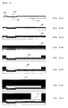
Fig. 1 is a sectional schematic view of every step of a semiconductor device for explaining Manufacturing Method A of a semiconductor device having a bump electrode of the present invention (Figs. A(a) to A(h)). -
Fig. 2 is a sectional schematic view of every step of a semiconductor device for explaining Manufacturing Method A of a semiconductor device having a bump electrode of the present invention (Figs. A(i) to A(p) ). -
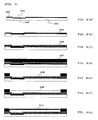
Fig. 3 is a sectional schematic view of every step of a semiconductor device for explaining Manufacturing Method B of a semiconductor device having a bump electrode of the present invention (Figs. B(a) to B(g) ). -
Fig. 4 is a sectional schematic view of every step of a semiconductor device for explaining Manufacturing Method B of a semiconductor device having a bump electrode of the present invention (Figs. B(h) to B(m) ). -
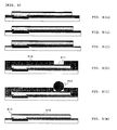
Fig. 5 is a sectional schematic view of every step of a semiconductor device for explaining Manufacturing Method C of a semiconductor device having a bump electrode of the present invention (Figs. C(a) to C(e)). -
Fig. 6 is a sectional schematic view of every step of a semiconductor device for explaining Manufacturing Method C of a semiconductor device having a bump electrode of the present invention (Figs. C(f) to C(k)). -
Fig. 7 is a sectional schematic view of every step of a semiconductor device for explaining Manufacturing Method D of a semiconductor device having a bump electrode of the present invention (Figs. D(a) to D(g)). -
Fig. 8 is a sectional schematic view of every step of a semiconductor device for explaining Manufacturing Method D of a semiconductor device having a bump electrode of the present invention (Figs. D(h) to D(1)). -
- 101, 201, 301, 401: Silicon substrate
- 102, 202, 302, 402: Electrode
- 103, 203, 303, 304: Insulating film
- 104, 204, 304, 404: Opening
- 105, 205, 305, 405: Titanium layer
- 106, 206, 306, 406: Copper layer
- 107: Photoresist (I)
- 108, 208, 308, 408: Opening
- 109, 209, 409: Copper layer
- 110: Photoresist (II)
- 111, 211: Opening
- 112, 210, 309, 410: Nickel layer
- 113, 310, 411: Gold layer
- 114, 212: Insulating film
- 116: Residue of copper layer
- 117, 311, 412: Concave
- 207, 307, 407: Photoresist
- 213: Bump electrode
- 214: Shoulder cutting
- Under such circumstances, the present invention has been made, and its object is to provide an etchant which is used for the manufacture of a semiconductor device using a semiconductor substrate having an electrode and which is capable of selectively etching copper without etching nickel and a method for manufacturing a semiconductor device using the same.
- In order to achieve the foregoing object, the present inventors made extensive and intensive investigations. As a result, it has been found that the foregoing problems can be solved by using an etchant containing hydrogen peroxide and, as an organic acid component, a specified hydroxy acid, namely citric acid or malic acid, in a specified composition. That is, the present invention is to provide an etchant which is used for the manufacture of a semiconductor device using a semiconductor substrate having an electrode and which is capable of selectively etching copper without etching nickel and a method for manufacturing a semiconductor device using the same.
-
- [1] An etchant for selective etching of copper which is used for the manufacture of a semiconductor device using a semiconductor substrate having an electrode, comprising hydrogen peroxide and citric acid and having a content of hydrogen peroxide of from 0.75 to 12 % by mass and a content of citric acid of from 1 to 20 % by mass, with a molar ratio of hydrogen peroxide and citric acid being in the range of from 0.3 to 5.
- [2] An etchant for selective etching of copper which is used for the manufacture of a semiconductor device using a semiconductor substrate having an electrode, comprising hydrogen peroxide and malic acid and having a content of hydrogen peroxide of from 0.75 to 12 % by mass and a content of malic acid of from 1.5 to 25 % by mass, with a molar ratio of hydrogen peroxide and malic acid being in the range of from 0.2 to 6.
- [3] The etchant for selective etching of copper as set forth above in [1], wherein the content of hydrogen peroxide is from 1.5 to 7 % by mass, the content of citric acid is from 2 to 15 % by mass, and the molar ratio of hydrogen peroxide and citric acid is in the range of from 0.3 to 5.
- [4] The etchant for selective etching of copper as set forth above in [2], wherein the content of hydrogen peroxide is from 1.5 to 4.5 % by mass, the content of malic acid is from 1 to 15 % by mass, and the molar ratio of hydrogen peroxide and malic acid is in the range of from 0.3 to 6.
- [5] A method for manufacturing a semiconductor device, comprising an etching step using the etchant for selective etching of copper as set forth above in any one of [1] to [4].
- [6] The method for manufacturing a semiconductor device as set forth above in [5], wherein the semiconductor device has a bump electrode.
- [7] The method for manufacturing a semiconductor device as set forth above in [5] or [6], comprising a redistribution layer forming step of forming a wiring on the electrode of the semiconductor substrate having an electrode.
- [8] The method for manufacturing a semiconductor device as set forth above in any one of [5] to [7], wherein the semiconductor device has a wiring to be formed using copper.
- According to the present invention, an etchant which is used for a manufacturing step of a semiconductor device using a semiconductor substrate having an electrode and which is capable of selectively etching copper without etching nickel and a method for manufacturing a semiconductor device using the same can be provided.
- The etchant of the present invention is a liquid which is used in an etching step in a manufacturing step of a semiconductor device using a semiconductor substrate having an electrode and which contains hydrogen peroxide and, as an organic acid component, citric acid or malic acid that is a specified hydroxy acid and has a specified composition.
- In the case where the etchant of the present invention contains citric acid as the organic acid component, it is required that a content of hydrogen peroxide is from 0.75 to 12 % by mass, and a content of citric acid is from 1 to 20 % by mass, with a molar ratio of hydrogen peroxide and citric acid being in the range of from 0.3 to 5. So far as the contents of the respective components in the etchant fall within the foregoing ranges, the control of hydrogen peroxide is easy; the concentration of hydrogen peroxide is stable; an appropriate etching rate and satisfactory etching performances are obtained; and it is possible to selectively etch copper without etching nickel. From the same viewpoints, it is preferable that the content of hydrogen peroxide is from 1 to 9 % by mass, and the content of citric acid is from 2 to 20 % by mass, with the molar ratio of hydrogen peroxide and citric acid being in the range of from 0.2 to 6; and it is more preferable that the content of hydrogen peroxide is from 1.5 to 7 % by mass, and the content of citric acid is from 2 to 15 % by mass, with the molar ratio of hydrogen peroxide and citric acid being in the range of from 0.3 to 5.
- In the case where the etchant of the present invention contains malic acid as the organic acid component, it is required that a content of hydrogen peroxide is from 0.75 to 12 % by mass, and a content of malic acid is from 1.5 to 25 % by mass, with a molar ratio of hydrogen peroxide and malic acid being in the range of from 0.2 to 6. So far as the contents of the respective components in the etchant fall within the foregoing ranges, the control of hydrogen peroxide is easy; the concentration of hydrogen peroxide is stable; an appropriate etching rate and satisfactory etching performances are obtained; and it is possible to selectively etch copper without etching nickel. From the same viewpoints, it is preferable that the content of hydrogen peroxide is from 1 to 9 % by mass, and the content of malic acid is from 2 to 20 % by mass, with the molar ratio of hydrogen peroxide and malic acid being in the range of from 0.2 to 6; and it is more preferable that the content of hydrogen peroxide is from 1.5 to 4.5 % by mass, and the content of malic acid is from 1 to 15 % by mass, with the molar ratio of hydrogen peroxide and malic acid being in the range of from 0.3 to 6.
- The etchant of the present invention preferably contains water as other component than hydrogen peroxide and the organic acid component. As the water, water from which metal ions, organic impurities, particle grains, and the like have been removed by means of distillation, an ion exchange treatment, a filter treatment, an adsorption treatment of various sort, or the like is preferable. In particular, pure water and ultra-pure water are preferable.
- The etchant of the present invention has such a characteristic feature that it selectively etches copper without etching nickel. Accordingly, the etchant of the present invention is suitably used for the etching step in the manufacturing step of a semiconductor device which uses nickel and copper and which is required to selectively etch copper without etching nickel especially among semiconductor devices.
- The manufacturing method of a semiconductor device of the present invention includes an etching step using the etchant of the present invention, and it is preferable that the semiconductor device has a bump electrode. Also, from the viewpoint of effectively utilizing the characteristic feature of the etchant of the present invention, which is capable of selectively etching copper without etching nickel, it is preferable that the etching step is characterized in that a member composed of nickel and a member composed of copper are in such a state that the both can be brought into contact with the etchant at the same time; and that the member composed of copper is etched. The manufacturing method of the present invention is hereunder more specifically described.
- A first embodiment of the manufacturing method of a semiconductor device of the present invention (hereinafter referred to as "Manufacturing Method A") includes a seed layer forming step A1; a photoresist (I) forming step A2; a redistribution layer forming step A3; a photoresist (II) forming step A4; a bump electrode forming step A5; and an etching step A6 using the etchant of the present invention in this order. Manufacturing Method A of the present invention is described in detail by reference to Figs. A(a) to A(p).
- Step A1 is a seed layer forming step of providing, on a semiconductor substrate having an electrode provided therewith, an insulating film having an opening from which the electrode is exposed, and further forming a seed layer on the opening and the insulating film. As shown in Fig. A(a), the semiconductor substrate having an electrode provided therewith as referred to herein is one in which an electronic circuit containing a semiconductor device which is manufactured by a well-known manufacturing method is, for example, formed on a surface of a
silicon substrate 101, and anelectrode 102 composed of an electrically conductive material such as, for example, aluminum, etc., which is called a pad, is formed on the surface on which the electronic circuit is formed. In addition to aluminum, aluminum alloys having titanium or copper added thereto, copper or copper alloys, gold, and the like can also be preferably exemplified as the electrically conductive material.
On thesemiconductor 101 having thiselectrode 102 provided therewith (the surface on which the electrode is formed), an insulatingfilm 103 composed of silicon oxide, etc. is formed, and in the insulatingfilm 103, anopening 104 corresponding to theelectrode 102 is formed so as to expose theelectrode 102. - Subsequently, as shown in Figs. A(b) and A(c), a seed layer is formed on the
opening 104 and the insulatingfilm 103 usually by means of sputtering. As a metal for forming the seed layer, titanium, copper, and the like are preferably exemplified, and as shown in Figs. A(b) and A(c), a layer such as a layer made of such a metal, atitanium layer 105, or acopper layer 106 can be provided in a plural number. Also, from the viewpoints of the adhesion to theelectrode 102 and the fabrication control of a semiconductor device, it is preferable to provide thetitanium layer 105 on the substrate. - Step A2 is a photoresist (I) forming step of opening a region including an area which is provided on the electrode of the seed layer and an area for forming a bump electrode and forming a photoresist (I) 107 having an
opening 108 for exposing the seed layer. First of all, as shown in Fig. A(d), the photoresist (I) 107 is formed on thecopper layer 106. Subsequently, as shown in Fig. A(e), by exposing with light and developing, the photoresist (I) 107 having theopening 108 for forming a redistribution layer connecting to a region including the area which is provided on theelectrode 102 of the seed layer and the area for forming a bump electrode as described later is formed. - Step A3 is a redistribution layer forming step of providing a wiring on the
opening 108 to perform redistribution. According to this redistribution layer forming step, a redistribution layer for forming a wiring on theelectrode 102 of thesemiconductor substrate 101 having theelectrode 102 is formed. A material such as copper, nickel, etc. is used for the wiring, and as shown in Fig. A(f), it is preferable that the wiring has acopper layer 109 formed of at least copper. Also, the wiring is in general provided by an electrolytic plating treatment of copper or nickel. - As shown in Figs. A (g) and A(h), Step A4 is a photoresist (II) forming step of removing the photoresist (I) 107 formed in Step A3 to form a photoresist (II) 110 so as to cover the seed layer and the wiring and further performing exposure with light and development to form an
opening 111 for forming a bump electrode on the photoresist (II) 110. This photoresist (II) 110 may be provided in the usual way. - As shown in Figs. A(i) and A(j), Step 5A is a bump electrode forming step of providing the
opening 111 in an area for forming a bump electrode of the photoresist (II) 110 in such a manner that thecopper layer 109 of the redistribution layer is exposed and forming a bump electrode having at least one layer of a nickel layer 112 composed of nickel in theopening 111.
The bump electrode can be formed by using, in addition to tin, lead or an alloy thereof (tin-lead alloy), gold, palladium, nickel, copper, etc. by means of electrolytic plating, and can be formed of a single layer or plural layers. For example, as shown in Fig. A(j), after providing the nickel layer 112, agold layer 113 is provided, whereby the bump electrode can be formed. In the manufacturing method of the present invention, when the at least one layer which forms the bump electrode is the nickel layer 112 composed of nickel, the performance to enable selective etching of copper without etching nickel which the etchant of the present invention has, can be effectively utilized. - Step A6 is an etching step of after removing the photoresist (II) 110 as shown in Fig. A(k), further etching an exposed portion which is not covered by the wiring such as the
copper layer 109 in the seed layer such as thetitanium layer 105, thecopper layer 106, etc. as shown in Figs. A(l) and A(m). In the etching step, it is required that the etchant of the present invention is used. By using the etchant of the present invention, the control of hydrogen peroxide in the etchant is easy; an appropriate etching rate and satisfactory etching performances are obtained; and it is possible to selectively etch copper without etching nickel. - A method of bringing the etchant into contact with an etching object is not particularly limited, and for example, a method of bringing the etchant into contact with the object by a mode such as dropping, spraying, etc., a method of dipping the object in the etchant, and the like can be adopted. In the present invention, a method of bringing the etchant into contact with the object by means of spraying is preferably adopted.
- A use temperature of the etchant is preferably a temperature of not higher than 50 °C, more preferably from 20 to 50 °C, still more preferably from 20 to 40°C, and especially preferably from 25 to 35 °C. When the temperature of the etchant is 50°C or higher, though the etching rate increases, the stability of the liquid is deteriorated, and it is difficult to keep the etching condition constant. By regulating the temperature of the etchant to not higher than 50°C, a change of composition of the etchant is controlled small, and a stable etching rate can be obtained. Also, when the temperature of the etchant is 20°C or higher, the etching rate does not become excessively slow, and the production efficiency is not remarkably lowered.
- As shown in Fig. A(l), in etching the
copper layer 106 in the etching step of Step A6, the side face of the nickel layer 112 is exposed to the etchant. In such case, when the etchant of the present invention is used, the formation of a concave 117 to be caused due to the matter that the nickel layer 112 is etched as shown in Fig. A(p) does not occur, and it is possible to selectively etch only thecopper layer 106. Also, in view of the fact that the etchant of the present invention has satisfactory etching performances, the generation of aresidue 116 of the copper layer as shown in Fig. A(o) does not occur. - In Manufacturing Method A of the present invention, as shown in Fig. A(n), an insulating
film 114 can be further formed in other portion than the area where the bump electrode is formed. For the formation of the insulatingfilm 114, an insulating organic material such as epoxy resins, polyimide resins, etc., or the like is preferably used. - A second embodiment of the manufacturing method of a semiconductor device of the present invention (hereinafter referred to as "Manufacturing Method B") includes a seed layer forming step Bl; a photoresist forming step B2; a redistribution layer forming step B3; an etching step B4 using the etchant of the present invention; an insulating film forming step B5 ; and a bump electrode forming step B6 in this order. Manufacturing Method B of the present invention is described in detail by reference to
Figs. B(a) to B(m) . - Step B1 is a seed layer forming step of providing, on a
semiconductor substrate 201 having anelectrode 202 provided therewith, an insulatingfilm 203 having an opening 204 from which theelectrode 202 is exposed, and further forming a seed layer on theopening 204 and the insulatingfilm 203. Step B1 is the same as the foregoing Step A1 as shown inFigs. B (a) to B(c) . - Step B2 is a photoresist forming step of opening a region including an area which is provided on the
electrode 202 of the seed layer composed of atitanium layer 205 and acopper layer 206 as provided in Step B1 and an area for forming a bump electrode and forming aphotoresist 207 having anopening 208 for exposing the seed layer. Step B2 is the same as the foregoing Step A2 as shown inFigs. B(d) and B(e). - Step B3 is a redistribution layer forming step of providing a wiring on the
opening 208 to perform redistribution. For the wiring, a material such as copper, nickel, etc. is used. For example, as shown inFigs. B(f) and B(g) , the redistribution layer can be formed by successively laminating acopper layer 209 and anickel layer 210. Also, the wiring is in general provided by an electrolytic plating treatment of copper or nickel. - Step B4 is an etching step of after removing the
photoresist 207 as shown inFig. B(h) , further etching an exposed portion which is not covered by the wiring such as thecopper layer 209 and thenickel layer 210 in the seed layer such as thetitanium layer 205, thecopper layer 206, etc. as shown inFigs. B(i) and B(j) . In the etching step, it is required that the etchant of the present invention is used. By using the etchant of the present invention, the control of hydrogen peroxide in the etchant is easy; an appropriate etching rate and satisfactory etching performances are obtained; and it is possible to selectively etch copper without etching nickel. Various conditions of etching in Step B4 are the same as those in Step A6. - As shown in
Fig. B(i) , in etching thecopper layer 206 in the etching step of Step B4, thenickel layer 210 is exposed to the etchant. In such case, when the etchant of the present invention is used, the formation of a shoulder cutting 214 to be caused due to the matter that thenickel layer 210 is etched as shown in Fig. A(m) does not occur, and it is possible to selectively etch only thecopper layer 206. Also, in view of the fact that the etchant of the present invention has satisfactory etching performances, the generation of a residue of the copper layer does not occur. - As shown in
Fig. B(k) , Step B5 is an insulating film forming step of forming an insulatingfilm 212 having anopening 211 in a region for providing a bump electrode.
For the formation of the insulatingfilm 212, an organic insulating material such as epoxies, polyimides, etc. is preferably used. The insulatingfilm 212 is formed by coating the organic insulating material by means of spin coating or the like and providing theopening 211 for exposing a redistribution layer portion (thenickel layer 210 in the case of Fig. B). Though a formation method thereof varies depending upon the organic insulating material which is used for the insulatingfilm 212, for example, after coating the organic insulating material, a photoresist is coated, and after exposing with light and developing the photoresist, the insulatingfilm 212 is etched to provide theopening 211; or in the case where the organic insulating material is a photosensitive material, after coating the organic insulating material, the resultant is directly exposed with light and developed, whereby the insulatingfilm 212 having theopening 211 can be formed, too. - Step B6 is a bump electrode forming step of forming a
bump electrode 213 in theopening 211. Thebump electrode 213 can be provided by mounting a solder ball. - A third embodiment of the manufacturing method of a semiconductor device of the present invention (hereinafter referred to as "Manufacturing Method C") includes a seed layer forming step C1; a photoresist forming step C2 ; a bump electrode forming step C3; and an etching step C4 using the etchant of the present invention in this order. Manufacturing Method C of the present invention is described in detail by reference to Figs. C(a) to C(k).
- Step C1 is a seed layer forming step of providing, on a
semiconductor substrate 301 having anelectrode 302 provided therewith, an insulatingfilm 303 having an opening 304 from which theelectrode 302 is exposed, and further forming a seed layer on theopening 304 and the insulatingfilm 303. Step C1 is the same as the foregoing Step A1 or Step B1 as shown in Figs. C(a) to C(c). - Step C2 is a photoresist forming step of opening a region including an area which is provided on the
electrode 302 of the seed layer composed of atitanium layer 305 and acopper layer 306 as provided in Step C1 and forming aphotoresist 307 having anopening 308 for exposing the seed layer. Step C2 is the same as the foregoing Step A2 or Step B2 as shown in Figs. C(d) and C(e). - Step C3 is a bump electrode forming step of forming a bump electrode having at least one layer of a
nickel layer 309 composed of nickel in theopening 309. Step C3 is the same as Step A5, except for the formation of theopening 111, and as shown in Figs. C(f) and C(g), after providing thenickel layer 309, agold layer 310 is provided, whereby the bump electrode can be formed. - Step C4 is an etching step of after removing the
photoresist 307 as shown in Fig. C(h), further etching an exposed portion which is not covered by the bump electrode such as thenickel layer 309 and thegold layer 310 in the seed layer such as thetitanium layer 305, thecopper layer 306, etc. as shown in Figs. C(i) and C(j). In the etching step, it is required that the etchant of the present invention is used. By using the etchant of the present invention, the control of hydrogen peroxide in the etchant is easy; an appropriate etching rate and satisfactory etching performances are obtained; and it is possible to selectively etch copper without etching nickel. Various conditions of etching in Step C4 are the same as those in Step A6. - As shown in Fig. C(i), in etching the
copper layer 306 in the etching step of Step C4, thenickel layer 309 is exposed to the etchant. In such case, when the etchant of the present invention is used, the formation of a concave 311 to be caused due to the matter that thenickel layer 309 is etched as shown in Fig. C(k) does not occur, and it is possible to selectively etch only thecopper layer 306. Also, in view of the fact that the etchant of the present invention has satisfactory etching performances, the generation of a residue of the copper layer does not occur. - A fourth embodiment of the manufacturing method of a semiconductor device of the present invention (hereinafter referred to as "Manufacturing Method D") includes a seed layer forming step D1; a photoresist forming step D2; a bump electrode forming step D3; and an etching step D4 using the etchant of the present invention in this order. The respective steps of Manufacturing Method D of the present invention are shown in Figs. D(a) to D(1).
As shown in Figs. D(a) to D(1), Manufacturing Method D is the same as Manufacturing Method C, except that in the bump electrode forming step D3, a bump electrode composed of three layers of acopper layer 409, anickel layer 410, and agold layer 411 is formed. - As shown in Fig. D(j), in etching a
copper layer 406 in the etching step of Step D4, thenickel layer 410 is exposed to the etchant. In such case, when the etchant of the present invention is used, the formation of a concave 412 to be caused due to the matter that thenickel layer 410 is etched as shown in Fig. D(1) does not occur, and it is possible to selectively etch only thecopper layer 406. Also, in view of the fact that the etchant of the present invention has satisfactory etching performances, the generation of a residue of the copper layer does not occur. - Among the manufacturing methods of the present invention, according to Manufacturing Methods A and B, the redistribution for forming a wiring on an electrode of a semiconductor substrate having the electrode is achieved, thereby obtaining a semiconductor device having a bump electrode. According to these manufacturing methods, it is possible to use a semiconductor substrate having a narrow pitch such that an electrode-to-electrode pitch is not more than 150 µm, preferably not more than 100 µm, and more preferably not more than 50 µm. Also, a semiconductor device having a narrow pitch such that a bump electrode-to-bump electrode pitch is not more than 500 µm, preferably not more than 250 µm, and more preferably not more than 200 µm can be obtained. Accordingly, the semiconductor device obtained by the manufacturing method of the present invention can thoroughly cope with downsizing, high integration and multi-functionalization in recent years.
- Next, the present invention is described in more detail with reference to the following Examples, but it should be construed that the present invention is not limited to these Examples at all.
- A silicon substrate on which copper had been deposited by means of sputtering (thickness of copper film: 5,000 angstrom) was dipped in an etchant of each of the Examples and Comparative Examples at 30 °C for 2 minutes, and a change in a film thickness before and after dipping was measured using a fluorescent X-ray analyzer ("SEA2110L", manufactured by SII Nano Technology Inc.), from which was then calculated an etching rate (µm/min).
- A substrate obtained by depositing nickel on a steel material by means of electrolytic plating (thickness of nickel film: 5 µm) was dipped in an etchant of each of the Examples and Comparative Examples at 30 °C for one hour, and a weight before and after dipping was measured, from which was then calculated an etching rate (angstrom/min).
- At the time of allowing an etchant of each of the Examples and Comparative Examples to stand under a condition at 50 °C for one week, a decomposition rate of hydrogen peroxide in each of the etchants was determined and evaluated according to the following criteria. It was decided that when the decomposition rate is less than 10 %, the etchant is excellent in stability; when the decomposition rate is 10 % or more and less than 20 %, although the etchant is not sufficient in view of economy and is required to take care of control of the liquid in view of safety, it does not involve a problem from the standpoint of practical use; and when the decomposition rate is 20 % or more, the etchant is a level at which it cannot be used.
- A: The decomposition rate is less than 10 %.
- B: The decomposition rate is 10 % or more and less than 20 %.
- C: The decomposition rate is 20 % or more.
- Semiconductor devices were manufactured according to the procedures of Manufacturing Methods A to D by using an etchant of each of the Examples and Comparative Examples. At that time, the etching temperature was set to 30 °C; and the etching time was set to be two times a time obtained through calculation by dividing a film of copper (film thickness: 3, 000 angstrom) provided as a seed layer of the semiconductor device by means of sputtering, by the etching rate obtained in the foregoing Evaluation Item 1.
With respect to the obtained semiconductor devices, the state of a concave (in the case of Manufacturing Methods A, C and D) or a shoulder cutting (in the case of Manufacturing Method B) of a nickel layer provided by means of electrolytic plating, and a residual state of the copper layer provided as a seed layer after etching were evaluated according to the following criteria, respectively. -
- A: The concave or should cutting of the nickel layer was not confirmed at all.
- B: The concave or should cutting of the nickel layer was slightly confirmed, but there is not involved a problem from the standpoint of practical use.
- C: The concave or should cutting of the nickel layer was remarkable, so that the resulting semiconductor device cannot be used.
-
- A: After etching, the survival of the copper layer was not confirmed at all.
- B: After etching, the survival of the copper layer was slightly confirmed, and a hindrance was generated from the standpoint of practical use.
- C: After etching, the survival of the copper layer was remarkable, so that the resulting semiconductor device cannot be used.
- An etchant to be used in each of the Examples and Comparative Examples was prepared according to a blending composition (% by mass) shown in Table 1 or 2.
- Semiconductor devices each having an electrode and a bump electrode were fabricated according to the procedures of Manufacturing Method A (Figs. A(a) to A(n)). Here, in the etching step shown in Figs. A(k) to A(m), etching of the photoresist 110, the
copper layer 106, and thetitanium layer 105 was successively carried out by using the etchant of each of the Examples and Comparative Examples.
Also, all of thetitanium layer 105 and thecopper layer 106 are provided by means of sputtering, and all of layer thicknesses thereof are 3,000 angstrom; and all of thecopper layer 109 of the redistribution layer and the nickel layer 112 and thegold layer 103 each forming a bump electrode are provided by means of electrolytic plating, and layer thicknesses thereof are 3 µm, 2 µm and 5 µm, respectively. With respect to the semiconductor devices obtained in the respective Examples and Comparative Examples, the results evaluated according to the foregoingEvaluation Item 4 are shown in Tables 1 and 2. Also, with respect to the etchants used in the respective Examples and Comparative Examples, the results evaluated according to the foregoing Evaluation Items 1 to 3 are shown in Tables 1 and 2. - Semiconductor devices each having an electrode and a bump electrode were fabricated according to the procedures of Manufacturing Method B (
Figs. B(a) to B(l) ). All of thetitanium layer 205 and thecopper layer 106 are provided by means of sputtering, and all of layer thicknesses thereof are 3,000 angstrom; and all of thecopper layer 209 and thenickel layer 210 provided in the redistribution step are provided by means of electrolytic plating, and layer thicknesses thereof are 3 µm and 2 µm, respectively.
In the etching step shown inFigs. B (h) to B(j) , etching of thephotoresist 207, thecopper layer 206, and thetitanium layer 205 was successively carried out by using an etchant. Here, the etchants used in Examples B1 to B51 and Comparative Examples B1 to B49 are the same as the etchants used in Examples A1 to A51 and Comparative Examples A1 to A49, respectively, and the evaluations of Evaluation Items 1 to 3 are also the same.
The semiconductor devices obtained in the respective Examples and Comparative Examples were evaluated according to the foregoingEvaluation Item 4. As a result, Examples B1 to B51 and Comparative Examples B1 to B49 revealed the same results as those of Examples A1 to A51 and Comparative Examples A1 to A49 using the same etchants, respectively. These results are shown in Tables 1 and 2. - Semiconductor devices each having an electrode and a bump electrode were fabricated according to the procedures of Manufacturing Method C (Figs. C(a) to C(j)). All of the
titanium layer 305 and thecopper layer 306 are provided by means of sputtering, and all of layer thicknesses thereof are 3,000 angstrom; and all of thenickel layer 309 and thegold layer 310 each provided as the bump electrode are provided by means of electrolytic plating, and layer thicknesses thereof are 3 µm and 10 µm, respectively.
In the etching step shown in Figs. C (h) to C(j), etching of thephotoresist 307, thecopper layer 306, and thetitanium layer 305 was successively carried out by using an etchant. Here, the etchants used in Examples C1 to C51 and Comparative Examples C1 to C49 are the same as the etchants used in Examples A1 to A51 and Comparative Examples A1 to A49, respectively, and the evaluations of Evaluation Items 1 to 3 are also the same.
The semiconductor devices obtained in the respective Examples and Comparative Examples were evaluated according to the foregoingEvaluation Item 4. As a result, Examples C1 to C51 and Comparative Examples C1 to C49 revealed the same results as those of Examples A1 to A51 and Comparative Examples A1 to A49 using the same etchants, respectively. These results are shown in Tables 1 and 2. - Semiconductor devices each having an electrode and a bump electrode were fabricated according to the procedures of Manufacturing Method D (Figs. D(a) to D(k)). All of the
titanium layer 405 and thecopper layer 406 are provided by means of sputtering, and all of layer thicknesses thereof are 3,000 angstrom; and all of thecopper layer 409, thenickel layer 410, and thegold layer 411 each provided as the bump electrode are provided by means of electrolytic plating, and layer thicknesses thereof are 10 µm, 3 µm and 5 µm, respectively.
In the etching step shown in Figs. D(i) to D(k), etching of thephotoresist 407, thecopper layer 406, and thetitanium layer 405 was successively carried out by using an etchant. Here, the etchants used in Examples D1 to D51 and Comparative Examples D1 to D49 are the same as the etchants used in Examples A1 to A51 and Comparative Examples A1 to A49, respectively, and the evaluations of Evaluation Items 1 to 3 are also the same.
The semiconductor devices obtained in the respective Examples and Comparative Examples were evaluated according to the foregoingEvaluation Item 4. As a result, Examples D1 to D51 and Comparative Examples D1 to D49 revealed the same results as those of Examples A1 to A51 and Comparative Examples A1 to A49 using the same etchants, respectively. These results are shown in Tables 1 and 2. -
Table 1 H2O2 Organic acid component Water H2O2/organic acid (molar ratio) Etching rate Stability of H2O2 Etching time (sec) Etching evaluation Concentration (% by mass) Kind Concentration (% by mass) Concentration (% by mass) Sputtered copper (µm/min) Electrolyzed Ni (angstrom/ min) Nickel layer Copper layer Concave Survival Example A to D 1 10 Citric acid 15 75 3.8 1.0 < 50 B 36 A A A to D2 10 Citric acid 12 78 4.7 1.0 < 50 B - - - A to D3 8 Citric acid 15 77 3.0 0.8 < 50 B - - - A to D4 8 Citric acid 10 82 4.5 0.8 < 50 B - - - A to D 5 8 Citric acid 9 83 5.0 0.8 < 50 B 45 A A A to D6 6 Citric acid 15 79 2.3 0.6 < 50 A - - - A to D7 6 Citric acid 10 84 3.4 0.6 < 50 A 60 A A A to D 8 6 Citric acid 7 87 4.8 0.6 < 50 A 60 A A A to D9 5 Citric acid 15 80 1.9 0.5 < 50 A - - - A to D10 5 Citric acid 10 85 2.8 0.5 < 50 A - - - A to D11 5 Citric acid 6 89 4.7 0.5 < 50 A 72 A A A to D 12 4 Citric acid 6 90 3.8 0.4 < 50 A 90 A A A to D13 4 Citric acid 5 91 4.5 0.4 < 50 A - - - A to D14 3 Citric acid 15 82 1.1 0.3 < 50 A - - - A to D15 3 Citric acid 10 87 1.7 0.3 < 50 A - - - A to D16 3 Citric acid 5 92 3.4 0.3 < 50 A - - - A to D17 3 Citric acid 4 93 4.2 0.3 < 50 A 120 A A A to D18 2 Citric acid 15 83 0.8 0.2 < 50 A - - - A to D19 2 Citric acid 10 88 1.1 0.2 < 50 A - - - A to D 20 2 Citric acid 3 95 3.8 0.2 < 50 A 180 A A A to D 21 1 Citric acid 10 89 0.6 0.2 < 50 A - - - A to D22 1 Citric acid 5 94 1.1 0.1 < 50 A - - - A to D23 1 Citric acid 2 97 2.8 0.1 < 50 A 360 A A Comparative Example A to D1 10 Citric acid 11 79 5.1 1.0 < 50 C - - - A to D2 10 Citric acid 10 80 5.7 1.0 < 50 C - - - A to D3 10 Citric acid 5 85 11.3 1.0 < 50 C - - - A to D 4 8 Citric acid 8 84 5.7 0.8 < 50 B 45 A B A to D 5 8 Citric acid 5 87 9.0 0.8 < 50 C - - - A to D6 6 Citric acid 6 88 5.7 0.6 < 50 A 60 A B A to D 7 6 Citric acid 5 89 6.8 0.6 < 50 B 60 A B A to D8 5 Citric acid 5 90 5.7 0.5 < 50 B 72 A B A to D 9 5 Citric acid 4 91 7.1 0.5 < 50 B - - - A to D10 5 Citric acid 3 92 9.4 0.4 < 50 B1 - - - A to D11 5 Citric acid 2 93 14.1 0.3 < 50 B - - - A to D12 5 Citric acid 1 94 28.3 0.2 < 50 B 180 A C A to D13 4 Citric acid 4 92 5.7 0.4 < 50 B 90 A B A to D 14 3 Citric acid 3 94 5.7 0.2 < 50 B 180 A B A to 15 3 Citric acid 2 95 8.5 0.2 < 50 B - - - A to D 16 3 Citric acid 1 96 17.0 0.1 < 50 B - - C A to D 17 2 Citric acid 2 96 5.7 0.1 < 50 A 360 A B A to D18 2 Citric acid 1 97 11.3 < 0.1 < 50 A - - - A to D19 1 Citric acid 1 98 5.7 < 0.1 < 50 A - - - A to D 20 1 Citric acid 0.5 98.5 11.3 < 0.1 < 50 A - - - A to D21 0.5 Citric acid 10 89.5 0.3 < 0.1 < 50 A - - - A to D 22 0.5 Citric acid 5 94.5 0.6 - < 0.1 < 50 A - - - A to D 23 5 Glycolic acid 8 87 1.4 0.5 1,500 B 72 C C A to D 24 5 Propionic acid 8 87 1.4 < 0.1 < 50 B - - - A to D 25 5 Butyric acid (butanoic acid) 8 87 1.6 < 0.1 < 50 B - - - A to D 26 5 Malonic acid 8 87 1.9 0.3 5,000 B 120 C C Concentration (% by mass) Kind Concentration (% by mass) Concentration (% by mass) Sputtered copper (µm/min) Electrolyzed Ni (angstrom/min) Nickel layer Copper layer Concave Survival A to D27 5 Succinic acid 8 87 2.2 - - - Sparingly soluble - - A to D 28 5 Tartaric acid 8 87 2.8 0.2 < 50 B 180 A C A to D 29 5 Fumaric acid 8 87 2.1 - - - Sparingly soluble - - A to D30 5 Maleic acid 8 87 2.1 0.7 5,000 B 51 - - A to D31 5 Diglycolic acid 8 87 2.5 < 0.1 < 50 B - - - A to D32 5 Glutaric acid 8 87 2.4 0.2 < 50 B 180 A C A to D33 5 Itaconic acid 8 87 2.4 0.4 < 50 B 90 A C -
Table 2 H2O2 Organic acid component Water H2O2/organic acid (molar ratio) Etching rate Stability of H2O2 Etching time (sec) Etching evaluation Concentration (% by mass) Kind Concentration (% by mass) Concentration (% by mass) Sputtered copper (µm/min) Electrolyzed Ni (angstrom/ min) Nickel layer Copper layer Concave Survival Example A to D 24 10 Malic acid 20 70 2.0 0.9 < 50 B 40 A A A to D25 10 Malic acid 10 80 3.9 0.9 < 50 B - - - A to D26 10 Malic acid 7 83 5.6 0.9 < 50 B - - - A to D 27 8 Malic acid 15 77 2.1 0.8 < 50 B - - - A to D28 8 Malic acid 10 82 3.2 0.8 < 50 B - - - A to D 29 8 Malic acid 8 84 3.9 0.8 < 50 B - - A to D 30 8 Malic acid 6 86 5.3 0.8 < 50 B 45 A A A to D31 6 Malic acid 15 79 1.6 0.6 < 50 B - - - A to D 32 6 Malic acid 10 84 2.4 0.6 < 50 B - - A to D 33 6 Malic acid 5 89 4.7 0.6 < 50 B - - - A to D 34 6 Malic acid 4 90 5.9 0.6 < 50 B 60 A A A to D 35 5 Malic acid 20 75 1.0 0.5 < 50 B - - - A to D36 5 Malic acid 15 80 1.3 0.5 < 50 B - - - A to D 37 5 Malic acid 10 85 2.0 0.5 < 50 B - - - A to D 38 5 Malic acid 4 91 4.9 0.5 < 50 B - - - A to D 39 4 Malic acid 6 90 2.6 0.4 < 50 A - - - A to D40 4 Malic acid 5 91 3.2 0.4 < 50 A 90 A A A to D41 4 Malic acid 3 93 5.3 0.4 < 50 A - - - A to D42 3 Malic acid 10 87 1.2 0.3 < 50 A - - - A to D 43 3 Malic acid 5 92 2.4 0.3 < 50 A - - - A to D 44 3 Malic acid 3 94 3.9 0.2 < 50 A - - - A to D 45 3 Malic acid 2 95 5.9 0.2 < 50 A - - - A to D46 2 Malic acid 10 88 0.8 0.2 < 50 A - - - A to D47 2 Malic acid 5 93 1.6 0.2 < 50 A 180 A A A to D 48 2 Malic acid 2 96 3.9 0.1 < 50 A - - - A to D 49 1 Malic acid 10 89 0.4 0.2 < 50 A - - - A to D 50 1 Malic acid 5 94 0.8 0.1 < 50 A - - - A to D51 1 Malic acid 2 97 2.0 0.1 < 50 A 360 A A Comparative Example A to D 34 10 Malic acid 6 84 6.6 0.9 < 50 C - - - A to D 35 10 Malic acid 5 85 7.9 0.9 < 50 C - - - A to D36 8 Malic acid 5 87 6.3 0.8 < 50 C - - - A to D 37 8 Malic acid 4 88 7.9 0.8 < 50 C - - - A to D 39 6 Malic acid 3 91 7.9 0.6 < 50 C - - - A to D 38 5 Malic acid 0.5 94.5 39.4 < 0.1 < 50 C - - - A to D 40 5 Malic acid 3 92 6.6 0.4 < 50 C - - - A to D41 5 Malic acid 2 93 9.9 0.3 < 50 C - - - A to D 42 5 Malic acid 1 94 19.7 0.2 < 50 C - - - A to D 43 4 Malic acid 2 94 7.9 0.3 < 50 B 120 A C A to D 44 3 Malic acid 1 96 11.8 0.1 < 50 A 360 A C A to D 45 2 Malic acid 1 97 7.9 < 0.1 < 50 A - - - A to D 46 1 Malic acid 1 98 3.9 < 0.1 < 50 A - - - A to D 47 1 Malic acid 0.5 98.5 7.9 < 0.1 < 50 A - - - - A to D 48 0.5 Malic acid 10 89.5 0.2 < 0.1 < 50 A - - - A to D 49 0.5 Malic acid 5 94.5 0.4 < 0.1 < 50 A - - - - The etchant of the present invention is used for the manufacturing step of a semiconductor device using a semiconductor substrate having an electrode.
Claims (8)
- An etchant for selective etching of copper which is used for the manufacture of a semiconductor device using a semiconductor substrate having an electrode, comprising hydrogen peroxide and citric acid and having a content of hydrogen peroxide of from 0.75 to 12 % by mass and a content of citric acid of from 1 to 20 % by mass, with a molar ratio of hydrogen peroxide and citric acid being in the range of from 0.3 to 5.
- An etchant for selective etching of copper which is used for the manufacture of a semiconductor device using a semiconductor substrate having an electrode, comprising hydrogen peroxide and malic acid and having a content of hydrogen peroxide of from 0.75 to 12 % by mass and a content of malic acid of from 1.5 to 25 % by mass, with a molar ratio of hydrogen peroxide and malic acid being in the range of from 0.2 to 6.
- The etchant for selective etching of copper according to claim 1, wherein the content of hydrogen peroxide is from 1.5 to 7 % by mass, the content of citric acid is from 2 to 15 % by mass, and the molar ratio of hydrogen peroxide and citric acid is in the range of from 0.3 to 5.
- The etchant for selective etching of copper according to claim 2, wherein the content of hydrogen peroxide is from 1.5 to 4.5 % by mass, the content of malic acid is from 1 to 15 % by mass, and the molar ratio of hydrogen peroxide and malic acid is in the range of from 0.3 to 6.
- A method for manufacturing a semiconductor device, comprising an etching step using the etchant for selective etching of copper according to any one of claims 1 to 4.
- The method for manufacturing a semiconductor device according to claim 5, wherein the semiconductor device has a bump electrode.
- The method for manufacturing a semiconductor device according to claim 5 or 6, comprising a redistribution layer forming step of forming a wiring on the electrode of the semiconductor substrate having an electrode.
- The method for manufacturing a semiconductor device according to any one of claims 5 to 7, wherein the semiconductor device has a wiring to be formed using copper.
Applications Claiming Priority (2)
| Application Number | Priority Date | Filing Date | Title |
|---|---|---|---|
| JP2009284173 | 2009-12-15 | ||
| PCT/JP2010/072506 WO2011074589A1 (en) | 2009-12-15 | 2010-12-14 | Etchant and method for manufacturing semiconductor device using same |
Publications (3)
| Publication Number | Publication Date |
|---|---|
| EP2515326A1 true EP2515326A1 (en) | 2012-10-24 |
| EP2515326A4 EP2515326A4 (en) | 2013-07-24 |
| EP2515326B1 EP2515326B1 (en) | 2018-09-26 |
Family
ID=44167341
Family Applications (1)
| Application Number | Title | Priority Date | Filing Date |
|---|---|---|---|
| EP10837615.3A Active EP2515326B1 (en) | 2009-12-15 | 2010-12-14 | Method for manufacturing semiconductor device using an etchant |
Country Status (6)
| Country | Link |
|---|---|
| US (1) | US8900478B2 (en) |
| EP (1) | EP2515326B1 (en) |
| JP (1) | JP5794147B2 (en) |
| CN (1) | CN102687251B (en) |
| TW (1) | TWI515337B (en) |
| WO (1) | WO2011074589A1 (en) |
Cited By (1)
| Publication number | Priority date | Publication date | Assignee | Title |
|---|---|---|---|---|
| FR3018151A1 (en) * | 2014-07-04 | 2015-09-04 | Commissariat Energie Atomique | METHOD FOR MAKING AN ELECTRIC INTERCONNECTION LEVEL |
Families Citing this family (9)
| Publication number | Priority date | Publication date | Assignee | Title |
|---|---|---|---|---|
| EP2862959A1 (en) | 2013-10-21 | 2015-04-22 | ATOTECH Deutschland GmbH | Method of selectively treating copper in the presence of further metal |
| JP6251043B2 (en) | 2014-01-08 | 2017-12-20 | 株式会社荏原製作所 | Etching solution, etching method, and solder bump manufacturing method |
| WO2016105404A1 (en) * | 2014-12-23 | 2016-06-30 | Intel Corporation | Thin channel region on wide subfin |
| US10332753B2 (en) * | 2017-01-13 | 2019-06-25 | International Business Machines Corporation | Wet etching of samarium selenium for piezoelectric processing |
| DE102017110076B4 (en) * | 2017-05-10 | 2024-08-22 | OSRAM Opto Semiconductors Gesellschaft mit beschränkter Haftung | Method for producing a radiation-emitting semiconductor component |
| JP7367700B2 (en) | 2018-11-20 | 2023-10-24 | 三菱瓦斯化学株式会社 | Etching solution for selectively etching copper and copper alloys and method for manufacturing semiconductor substrates using the same |
| US11121101B2 (en) * | 2020-01-30 | 2021-09-14 | International Business Machines Corporation | Flip chip packaging rework |
| KR102953225B1 (en) * | 2021-07-06 | 2026-04-16 | 도쿄엘렉트론가부시키가이샤 | Selective membrane formation using self-assembled monolayers |
| WO2026042661A1 (en) * | 2024-08-20 | 2026-02-26 | 三菱瓦斯化学株式会社 | Aqueous composition, etching method using same, and method for manufacturing semiconductor substrate |
Family Cites Families (13)
| Publication number | Priority date | Publication date | Assignee | Title |
|---|---|---|---|---|
| JP3654485B2 (en) | 1997-12-26 | 2005-06-02 | 富士通株式会社 | Manufacturing method of semiconductor device |
| JP3524441B2 (en) * | 1999-08-10 | 2004-05-10 | 新光電気工業株式会社 | Wiring formation method |
| US6511901B1 (en) * | 1999-11-05 | 2003-01-28 | Atmel Corporation | Metal redistribution layer having solderable pads and wire bondable pads |
| US20020048953A1 (en) | 2000-06-16 | 2002-04-25 | Radha Nayak | Chemical mixture for copper removal in electroplating systems |
| TW449813B (en) * | 2000-10-13 | 2001-08-11 | Advanced Semiconductor Eng | Semiconductor device with bump electrode |
| US8372757B2 (en) * | 2003-10-20 | 2013-02-12 | Novellus Systems, Inc. | Wet etching methods for copper removal and planarization in semiconductor processing |
| US7465408B1 (en) * | 2003-12-03 | 2008-12-16 | Advanced Micro Devices, Inc. | Solutions for controlled, selective etching of copper |
| JP2005175128A (en) * | 2003-12-10 | 2005-06-30 | Fujitsu Ltd | Semiconductor device and manufacturing method thereof |
| JP2006120664A (en) * | 2004-10-19 | 2006-05-11 | Nec Electronics Corp | Manufacturing method of semiconductor device |
| JP4393343B2 (en) | 2004-10-22 | 2010-01-06 | 株式会社東芝 | Manufacturing method of semiconductor device |
| DE102005038414A1 (en) | 2005-08-12 | 2007-02-15 | Basf Aktiengesellschaft | Stabilized etching solutions for etching Cu and Cu / Ni layers |
| US7541251B2 (en) * | 2006-02-10 | 2009-06-02 | California Micro Devices | Wire bond and redistribution layer process |
| JP2009091656A (en) * | 2007-09-19 | 2009-04-30 | Nagase Chemtex Corp | Etching composition |
-
2010
- 2010-12-14 JP JP2011546137A patent/JP5794147B2/en active Active
- 2010-12-14 EP EP10837615.3A patent/EP2515326B1/en active Active
- 2010-12-14 US US13/516,524 patent/US8900478B2/en active Active
- 2010-12-14 CN CN201080057354.XA patent/CN102687251B/en active Active
- 2010-12-14 WO PCT/JP2010/072506 patent/WO2011074589A1/en not_active Ceased
- 2010-12-15 TW TW099144000A patent/TWI515337B/en active
Cited By (1)
| Publication number | Priority date | Publication date | Assignee | Title |
|---|---|---|---|---|
| FR3018151A1 (en) * | 2014-07-04 | 2015-09-04 | Commissariat Energie Atomique | METHOD FOR MAKING AN ELECTRIC INTERCONNECTION LEVEL |
Also Published As
| Publication number | Publication date |
|---|---|
| US20120261608A1 (en) | 2012-10-18 |
| CN102687251B (en) | 2016-02-17 |
| TW201127995A (en) | 2011-08-16 |
| EP2515326B1 (en) | 2018-09-26 |
| WO2011074589A1 (en) | 2011-06-23 |
| US8900478B2 (en) | 2014-12-02 |
| CN102687251A (en) | 2012-09-19 |
| JP5794147B2 (en) | 2015-10-14 |
| EP2515326A4 (en) | 2013-07-24 |
| JPWO2011074589A1 (en) | 2013-04-25 |
| TWI515337B (en) | 2016-01-01 |
Similar Documents
| Publication | Publication Date | Title |
|---|---|---|
| EP2515326B1 (en) | Method for manufacturing semiconductor device using an etchant | |
| EP2518759B1 (en) | Method for manufacturing semiconductor device using an etchant | |
| US6457234B1 (en) | Process for manufacturing self-aligned corrosion stop for copper C4 and wirebond | |
| CN102569171B (en) | Circuit structure for improving crown defects and its manufacturing method | |
| US6436300B2 (en) | Method of manufacturing electronic components | |
| US20100166952A1 (en) | Nano-metal solution, nano-metal complex grains and manufacturing method of metal film | |
| EP3125278B1 (en) | Semiconductor device and semiconductor device manufacturing method | |
| US20030219976A1 (en) | Using stabilizers in electroless solutions to inhibit plating of fuses | |
| US11516907B2 (en) | Glass wiring board | |
| KR102258660B1 (en) | Liquid composition for etching metal containing Cu and method of fabricating a semiconductor device using the same | |
| KR101643333B1 (en) | Method of fabricating bump structure | |
| US7855144B2 (en) | Method of forming metal lines and bumps for semiconductor devices | |
| JPH04217323A (en) | Manufacture of bump electrode for semiconductor device | |
| CN1103119C (en) | Method for Single Mask C4 Solder Bump Fabrication | |
| US11495557B2 (en) | Semiconductor device and method of manufacturing the same | |
| TWI707068B (en) | Method for preparing alloy thin film by controlling surface-limited redox reaction time | |
| JP3335883B2 (en) | Manufacturing method of bump electrode | |
| JP3471723B2 (en) | Multilayer wiring for bare chip mounting and its manufacturing method | |
| JP3308882B2 (en) | Method for manufacturing electrode structure of semiconductor device |
Legal Events
| Date | Code | Title | Description |
|---|---|---|---|
| PUAI | Public reference made under article 153(3) epc to a published international application that has entered the european phase |
Free format text: ORIGINAL CODE: 0009012 |
|
| 17P | Request for examination filed |
Effective date: 20120621 |
|
| AK | Designated contracting states |
Kind code of ref document: A1 Designated state(s): AL AT BE BG CH CY CZ DE DK EE ES FI FR GB GR HR HU IE IS IT LI LT LU LV MC MK MT NL NO PL PT RO RS SE SI SK SM TR |
|
| DAX | Request for extension of the european patent (deleted) | ||
| A4 | Supplementary search report drawn up and despatched |
Effective date: 20130625 |
|
| RIC1 | Information provided on ipc code assigned before grant |
Ipc: H01L 23/00 20060101ALI20130619BHEP Ipc: H01L 21/3213 20060101ALI20130619BHEP Ipc: C23F 1/18 20060101ALI20130619BHEP Ipc: C23F 1/02 20060101AFI20130619BHEP |
|
| REG | Reference to a national code |
Ref country code: DE Ref legal event code: R079 Ref document number: 602010053939 Country of ref document: DE Free format text: PREVIOUS MAIN CLASS: H01L0021308000 Ipc: H01L0021321300 |
|
| GRAP | Despatch of communication of intention to grant a patent |
Free format text: ORIGINAL CODE: EPIDOSNIGR1 |
|
| RIC1 | Information provided on ipc code assigned before grant |
Ipc: H01L 23/00 20060101ALI20180417BHEP Ipc: H01L 21/3213 20060101AFI20180417BHEP Ipc: C23F 1/44 20060101ALI20180417BHEP Ipc: C23F 1/02 20060101ALI20180417BHEP Ipc: C23F 1/18 20060101ALI20180417BHEP |
|
| INTG | Intention to grant announced |
Effective date: 20180507 |
|
| GRAS | Grant fee paid |
Free format text: ORIGINAL CODE: EPIDOSNIGR3 |
|
| GRAA | (expected) grant |
Free format text: ORIGINAL CODE: 0009210 |
|
| AK | Designated contracting states |
Kind code of ref document: B1 Designated state(s): AL AT BE BG CH CY CZ DE DK EE ES FI FR GB GR HR HU IE IS IT LI LT LU LV MC MK MT NL NO PL PT RO RS SE SI SK SM TR |
|
| REG | Reference to a national code |
Ref country code: GB Ref legal event code: FG4D |
|
| REG | Reference to a national code |
Ref country code: CH Ref legal event code: EP |
|
| REG | Reference to a national code |
Ref country code: AT Ref legal event code: REF Ref document number: 1047018 Country of ref document: AT Kind code of ref document: T Effective date: 20181015 |
|
| REG | Reference to a national code |
Ref country code: IE Ref legal event code: FG4D |
|
| REG | Reference to a national code |
Ref country code: DE Ref legal event code: R096 Ref document number: 602010053939 Country of ref document: DE |
|
| REG | Reference to a national code |
Ref country code: NL Ref legal event code: MP Effective date: 20180926 |
|
| PG25 | Lapsed in a contracting state [announced via postgrant information from national office to epo] |
Ref country code: FI Free format text: LAPSE BECAUSE OF FAILURE TO SUBMIT A TRANSLATION OF THE DESCRIPTION OR TO PAY THE FEE WITHIN THE PRESCRIBED TIME-LIMIT Effective date: 20180926 Ref country code: BG Free format text: LAPSE BECAUSE OF FAILURE TO SUBMIT A TRANSLATION OF THE DESCRIPTION OR TO PAY THE FEE WITHIN THE PRESCRIBED TIME-LIMIT Effective date: 20181226 Ref country code: SE Free format text: LAPSE BECAUSE OF FAILURE TO SUBMIT A TRANSLATION OF THE DESCRIPTION OR TO PAY THE FEE WITHIN THE PRESCRIBED TIME-LIMIT Effective date: 20180926 Ref country code: NO Free format text: LAPSE BECAUSE OF FAILURE TO SUBMIT A TRANSLATION OF THE DESCRIPTION OR TO PAY THE FEE WITHIN THE PRESCRIBED TIME-LIMIT Effective date: 20181226 Ref country code: RS Free format text: LAPSE BECAUSE OF FAILURE TO SUBMIT A TRANSLATION OF THE DESCRIPTION OR TO PAY THE FEE WITHIN THE PRESCRIBED TIME-LIMIT Effective date: 20180926 Ref country code: GR Free format text: LAPSE BECAUSE OF FAILURE TO SUBMIT A TRANSLATION OF THE DESCRIPTION OR TO PAY THE FEE WITHIN THE PRESCRIBED TIME-LIMIT Effective date: 20181227 Ref country code: LT Free format text: LAPSE BECAUSE OF FAILURE TO SUBMIT A TRANSLATION OF THE DESCRIPTION OR TO PAY THE FEE WITHIN THE PRESCRIBED TIME-LIMIT Effective date: 20180926 |
|
| REG | Reference to a national code |
Ref country code: LT Ref legal event code: MG4D |
|
| PG25 | Lapsed in a contracting state [announced via postgrant information from national office to epo] |
Ref country code: HR Free format text: LAPSE BECAUSE OF FAILURE TO SUBMIT A TRANSLATION OF THE DESCRIPTION OR TO PAY THE FEE WITHIN THE PRESCRIBED TIME-LIMIT Effective date: 20180926 Ref country code: LV Free format text: LAPSE BECAUSE OF FAILURE TO SUBMIT A TRANSLATION OF THE DESCRIPTION OR TO PAY THE FEE WITHIN THE PRESCRIBED TIME-LIMIT Effective date: 20180926 Ref country code: AL Free format text: LAPSE BECAUSE OF FAILURE TO SUBMIT A TRANSLATION OF THE DESCRIPTION OR TO PAY THE FEE WITHIN THE PRESCRIBED TIME-LIMIT Effective date: 20180926 |
|
| REG | Reference to a national code |
Ref country code: AT Ref legal event code: MK05 Ref document number: 1047018 Country of ref document: AT Kind code of ref document: T Effective date: 20180926 |
|
| PG25 | Lapsed in a contracting state [announced via postgrant information from national office to epo] |
Ref country code: ES Free format text: LAPSE BECAUSE OF FAILURE TO SUBMIT A TRANSLATION OF THE DESCRIPTION OR TO PAY THE FEE WITHIN THE PRESCRIBED TIME-LIMIT Effective date: 20180926 Ref country code: IS Free format text: LAPSE BECAUSE OF FAILURE TO SUBMIT A TRANSLATION OF THE DESCRIPTION OR TO PAY THE FEE WITHIN THE PRESCRIBED TIME-LIMIT Effective date: 20190126 Ref country code: CZ Free format text: LAPSE BECAUSE OF FAILURE TO SUBMIT A TRANSLATION OF THE DESCRIPTION OR TO PAY THE FEE WITHIN THE PRESCRIBED TIME-LIMIT Effective date: 20180926 Ref country code: AT Free format text: LAPSE BECAUSE OF FAILURE TO SUBMIT A TRANSLATION OF THE DESCRIPTION OR TO PAY THE FEE WITHIN THE PRESCRIBED TIME-LIMIT Effective date: 20180926 Ref country code: NL Free format text: LAPSE BECAUSE OF FAILURE TO SUBMIT A TRANSLATION OF THE DESCRIPTION OR TO PAY THE FEE WITHIN THE PRESCRIBED TIME-LIMIT Effective date: 20180926 Ref country code: RO Free format text: LAPSE BECAUSE OF FAILURE TO SUBMIT A TRANSLATION OF THE DESCRIPTION OR TO PAY THE FEE WITHIN THE PRESCRIBED TIME-LIMIT Effective date: 20180926 Ref country code: EE Free format text: LAPSE BECAUSE OF FAILURE TO SUBMIT A TRANSLATION OF THE DESCRIPTION OR TO PAY THE FEE WITHIN THE PRESCRIBED TIME-LIMIT Effective date: 20180926 Ref country code: PL Free format text: LAPSE BECAUSE OF FAILURE TO SUBMIT A TRANSLATION OF THE DESCRIPTION OR TO PAY THE FEE WITHIN THE PRESCRIBED TIME-LIMIT Effective date: 20180926 Ref country code: IT Free format text: LAPSE BECAUSE OF FAILURE TO SUBMIT A TRANSLATION OF THE DESCRIPTION OR TO PAY THE FEE WITHIN THE PRESCRIBED TIME-LIMIT Effective date: 20180926 |
|
| PG25 | Lapsed in a contracting state [announced via postgrant information from national office to epo] |
Ref country code: SM Free format text: LAPSE BECAUSE OF FAILURE TO SUBMIT A TRANSLATION OF THE DESCRIPTION OR TO PAY THE FEE WITHIN THE PRESCRIBED TIME-LIMIT Effective date: 20180926 Ref country code: PT Free format text: LAPSE BECAUSE OF FAILURE TO SUBMIT A TRANSLATION OF THE DESCRIPTION OR TO PAY THE FEE WITHIN THE PRESCRIBED TIME-LIMIT Effective date: 20190126 Ref country code: SK Free format text: LAPSE BECAUSE OF FAILURE TO SUBMIT A TRANSLATION OF THE DESCRIPTION OR TO PAY THE FEE WITHIN THE PRESCRIBED TIME-LIMIT Effective date: 20180926 |
|
| REG | Reference to a national code |
Ref country code: DE Ref legal event code: R097 Ref document number: 602010053939 Country of ref document: DE |
|
| PG25 | Lapsed in a contracting state [announced via postgrant information from national office to epo] |
Ref country code: DK Free format text: LAPSE BECAUSE OF FAILURE TO SUBMIT A TRANSLATION OF THE DESCRIPTION OR TO PAY THE FEE WITHIN THE PRESCRIBED TIME-LIMIT Effective date: 20180926 |
|
| REG | Reference to a national code |
Ref country code: CH Ref legal event code: PL |
|
| PLBE | No opposition filed within time limit |
Free format text: ORIGINAL CODE: 0009261 |
|
| STAA | Information on the status of an ep patent application or granted ep patent |
Free format text: STATUS: NO OPPOSITION FILED WITHIN TIME LIMIT |
|
| GBPC | Gb: european patent ceased through non-payment of renewal fee |
Effective date: 20181226 |
|
| PG25 | Lapsed in a contracting state [announced via postgrant information from national office to epo] |
Ref country code: LU Free format text: LAPSE BECAUSE OF NON-PAYMENT OF DUE FEES Effective date: 20181214 Ref country code: MC Free format text: LAPSE BECAUSE OF FAILURE TO SUBMIT A TRANSLATION OF THE DESCRIPTION OR TO PAY THE FEE WITHIN THE PRESCRIBED TIME-LIMIT Effective date: 20180926 |
|
| 26N | No opposition filed |
Effective date: 20190627 |
|
| REG | Reference to a national code |
Ref country code: IE Ref legal event code: MM4A |
|
| REG | Reference to a national code |
Ref country code: BE Ref legal event code: MM Effective date: 20181231 |
|
| PG25 | Lapsed in a contracting state [announced via postgrant information from national office to epo] |
Ref country code: SI Free format text: LAPSE BECAUSE OF FAILURE TO SUBMIT A TRANSLATION OF THE DESCRIPTION OR TO PAY THE FEE WITHIN THE PRESCRIBED TIME-LIMIT Effective date: 20180926 Ref country code: IE Free format text: LAPSE BECAUSE OF NON-PAYMENT OF DUE FEES Effective date: 20181214 Ref country code: FR Free format text: LAPSE BECAUSE OF NON-PAYMENT OF DUE FEES Effective date: 20181231 |
|
| PG25 | Lapsed in a contracting state [announced via postgrant information from national office to epo] |
Ref country code: BE Free format text: LAPSE BECAUSE OF NON-PAYMENT OF DUE FEES Effective date: 20181231 |
|
| PG25 | Lapsed in a contracting state [announced via postgrant information from national office to epo] |
Ref country code: CH Free format text: LAPSE BECAUSE OF NON-PAYMENT OF DUE FEES Effective date: 20181231 Ref country code: GB Free format text: LAPSE BECAUSE OF NON-PAYMENT OF DUE FEES Effective date: 20181226 Ref country code: LI Free format text: LAPSE BECAUSE OF NON-PAYMENT OF DUE FEES Effective date: 20181231 |
|
| PG25 | Lapsed in a contracting state [announced via postgrant information from national office to epo] |
Ref country code: MT Free format text: LAPSE BECAUSE OF NON-PAYMENT OF DUE FEES Effective date: 20181214 |
|
| PG25 | Lapsed in a contracting state [announced via postgrant information from national office to epo] |
Ref country code: TR Free format text: LAPSE BECAUSE OF FAILURE TO SUBMIT A TRANSLATION OF THE DESCRIPTION OR TO PAY THE FEE WITHIN THE PRESCRIBED TIME-LIMIT Effective date: 20180926 |
|
| PG25 | Lapsed in a contracting state [announced via postgrant information from national office to epo] |
Ref country code: MK Free format text: LAPSE BECAUSE OF NON-PAYMENT OF DUE FEES Effective date: 20180926 Ref country code: HU Free format text: LAPSE BECAUSE OF FAILURE TO SUBMIT A TRANSLATION OF THE DESCRIPTION OR TO PAY THE FEE WITHIN THE PRESCRIBED TIME-LIMIT; INVALID AB INITIO Effective date: 20101214 Ref country code: CY Free format text: LAPSE BECAUSE OF FAILURE TO SUBMIT A TRANSLATION OF THE DESCRIPTION OR TO PAY THE FEE WITHIN THE PRESCRIBED TIME-LIMIT Effective date: 20180926 |
|
| P01 | Opt-out of the competence of the unified patent court (upc) registered |
Effective date: 20230515 |
|
| REG | Reference to a national code |
Ref country code: DE Ref legal event code: R079 Ref document number: 602010053939 Country of ref document: DE Free format text: PREVIOUS MAIN CLASS: H01L0021321300 Ipc: H10P0050260000 |
|
| PGFP | Annual fee paid to national office [announced via postgrant information from national office to epo] |
Ref country code: DE Payment date: 20251028 Year of fee payment: 16 |