EP2515308A1 - Nuclear fusion target, nuclear fusion device, and nuclear fusion method - Google Patents
Nuclear fusion target, nuclear fusion device, and nuclear fusion method Download PDFInfo
- Publication number
- EP2515308A1 EP2515308A1 EP10837638A EP10837638A EP2515308A1 EP 2515308 A1 EP2515308 A1 EP 2515308A1 EP 10837638 A EP10837638 A EP 10837638A EP 10837638 A EP10837638 A EP 10837638A EP 2515308 A1 EP2515308 A1 EP 2515308A1
- Authority
- EP
- European Patent Office
- Prior art keywords
- nuclear fusion
- target
- layer
- laser light
- tritium
- Prior art date
- Legal status (The legal status is an assumption and is not a legal conclusion. Google has not performed a legal analysis and makes no representation as to the accuracy of the status listed.)
- Granted
Links
- 230000004927 fusion Effects 0.000 title claims abstract description 87
- 238000007500 overflow downdraw method Methods 0.000 title claims description 11
- 239000010409 thin film Substances 0.000 claims abstract description 44
- 229910052805 deuterium Inorganic materials 0.000 claims abstract description 40
- YZCKVEUIGOORGS-OUBTZVSYSA-N Deuterium Chemical compound [2H] YZCKVEUIGOORGS-OUBTZVSYSA-N 0.000 claims abstract description 35
- YZCKVEUIGOORGS-NJFSPNSNSA-N Tritium Chemical compound [3H] YZCKVEUIGOORGS-NJFSPNSNSA-N 0.000 claims abstract description 27
- 229910052722 tritium Inorganic materials 0.000 claims abstract description 27
- 230000001678 irradiating effect Effects 0.000 claims abstract description 20
- 239000010408 film Substances 0.000 claims description 19
- UFHFLCQGNIYNRP-UHFFFAOYSA-N Hydrogen Chemical compound [H][H] UFHFLCQGNIYNRP-UHFFFAOYSA-N 0.000 claims description 17
- 229910052739 hydrogen Inorganic materials 0.000 claims description 17
- 239000001257 hydrogen Substances 0.000 claims description 17
- 239000011343 solid material Substances 0.000 claims description 8
- 229910052751 metal Inorganic materials 0.000 claims description 5
- 239000002184 metal Substances 0.000 claims description 5
- 239000000758 substrate Substances 0.000 abstract description 35
- 230000001939 inductive effect Effects 0.000 abstract description 6
- 238000004519 manufacturing process Methods 0.000 description 9
- 238000000034 method Methods 0.000 description 9
- XLYOFNOQVPJJNP-ZSJDYOACSA-N Heavy water Chemical compound [2H]O[2H] XLYOFNOQVPJJNP-ZSJDYOACSA-N 0.000 description 8
- 150000002500 ions Chemical class 0.000 description 7
- -1 polyethylene Polymers 0.000 description 6
- 238000010884 ion-beam technique Methods 0.000 description 5
- 239000000463 material Substances 0.000 description 5
- 238000010586 diagram Methods 0.000 description 4
- 230000008569 process Effects 0.000 description 4
- 239000004793 Polystyrene Substances 0.000 description 3
- 229920002223 polystyrene Polymers 0.000 description 3
- 230000004044 response Effects 0.000 description 3
- KDLHZDBZIXYQEI-UHFFFAOYSA-N Palladium Chemical compound [Pd] KDLHZDBZIXYQEI-UHFFFAOYSA-N 0.000 description 2
- RTAQQCXQSZGOHL-UHFFFAOYSA-N Titanium Chemical compound [Ti] RTAQQCXQSZGOHL-UHFFFAOYSA-N 0.000 description 2
- 230000001133 acceleration Effects 0.000 description 2
- 229910001385 heavy metal Inorganic materials 0.000 description 2
- 239000004033 plastic Substances 0.000 description 2
- 229920003023 plastic Polymers 0.000 description 2
- 229910052719 titanium Inorganic materials 0.000 description 2
- 239000010936 titanium Substances 0.000 description 2
- 229920002799 BoPET Polymers 0.000 description 1
- OKTJSMMVPCPJKN-UHFFFAOYSA-N Carbon Chemical compound [C] OKTJSMMVPCPJKN-UHFFFAOYSA-N 0.000 description 1
- 239000005041 Mylar™ Substances 0.000 description 1
- 239000004698 Polyethylene Substances 0.000 description 1
- 229910052782 aluminium Inorganic materials 0.000 description 1
- XAGFODPZIPBFFR-UHFFFAOYSA-N aluminium Chemical compound [Al] XAGFODPZIPBFFR-UHFFFAOYSA-N 0.000 description 1
- 229910052799 carbon Inorganic materials 0.000 description 1
- 239000011248 coating agent Substances 0.000 description 1
- 238000000576 coating method Methods 0.000 description 1
- 239000013078 crystal Substances 0.000 description 1
- 238000000151 deposition Methods 0.000 description 1
- 238000009792 diffusion process Methods 0.000 description 1
- 230000000694 effects Effects 0.000 description 1
- 230000004992 fission Effects 0.000 description 1
- 230000006872 improvement Effects 0.000 description 1
- 230000010354 integration Effects 0.000 description 1
- 230000004048 modification Effects 0.000 description 1
- 238000012986 modification Methods 0.000 description 1
- 239000011368 organic material Substances 0.000 description 1
- 229910052763 palladium Inorganic materials 0.000 description 1
- 229920000573 polyethylene Polymers 0.000 description 1
- 230000036278 prepulse Effects 0.000 description 1
- 229910052594 sapphire Inorganic materials 0.000 description 1
- 239000010980 sapphire Substances 0.000 description 1
- 238000007740 vapor deposition Methods 0.000 description 1
Images
Classifications
-
- G—PHYSICS
- G21—NUCLEAR PHYSICS; NUCLEAR ENGINEERING
- G21B—FUSION REACTORS
- G21B1/00—Thermonuclear fusion reactors
- G21B1/03—Thermonuclear fusion reactors with inertial plasma confinement
-
- H—ELECTRICITY
- H05—ELECTRIC TECHNIQUES NOT OTHERWISE PROVIDED FOR
- H05H—PLASMA TECHNIQUE; PRODUCTION OF ACCELERATED ELECTRICALLY-CHARGED PARTICLES OR OF NEUTRONS; PRODUCTION OR ACCELERATION OF NEUTRAL MOLECULAR OR ATOMIC BEAMS
- H05H6/00—Targets for producing nuclear reactions
-
- G—PHYSICS
- G21—NUCLEAR PHYSICS; NUCLEAR ENGINEERING
- G21B—FUSION REACTORS
- G21B1/00—Thermonuclear fusion reactors
- G21B1/11—Details
- G21B1/15—Particle injectors for producing thermonuclear fusion reactions, e.g. pellet injectors
-
- G—PHYSICS
- G21—NUCLEAR PHYSICS; NUCLEAR ENGINEERING
- G21B—FUSION REACTORS
- G21B1/00—Thermonuclear fusion reactors
- G21B1/11—Details
- G21B1/19—Targets for producing thermonuclear fusion reactions, e.g. pellets for irradiation by laser or charged particle beams
-
- G—PHYSICS
- G21—NUCLEAR PHYSICS; NUCLEAR ENGINEERING
- G21B—FUSION REACTORS
- G21B3/00—Low temperature nuclear fusion reactors, e.g. alleged cold fusion reactors
- G21B3/006—Fusion by impact, e.g. cluster/beam interaction, ion beam collisions, impact on a target
-
- Y—GENERAL TAGGING OF NEW TECHNOLOGICAL DEVELOPMENTS; GENERAL TAGGING OF CROSS-SECTIONAL TECHNOLOGIES SPANNING OVER SEVERAL SECTIONS OF THE IPC; TECHNICAL SUBJECTS COVERED BY FORMER USPC CROSS-REFERENCE ART COLLECTIONS [XRACs] AND DIGESTS
- Y02—TECHNOLOGIES OR APPLICATIONS FOR MITIGATION OR ADAPTATION AGAINST CLIMATE CHANGE
- Y02E—REDUCTION OF GREENHOUSE GAS [GHG] EMISSIONS, RELATED TO ENERGY GENERATION, TRANSMISSION OR DISTRIBUTION
- Y02E30/00—Energy generation of nuclear origin
- Y02E30/10—Nuclear fusion reactors
Definitions
- the present invention relates to a nuclear fusion target, nuclear fusion device, and nuclear fusion method using laser light.
- two laser pulses are successively made incident at a predetermined time interval (300psec) onto a target prepared by forming a film of deuterium substituted polyethylene (C 2 D 4 ) X on an aluminum plate to induce a nuclear fusion reaction.
- Patent Document 1 Japanese Patent Application Laid-Open No. 2002-107494
- the nuclear fusion production method described in non-patent document 1 above in which the target is plasmatized by the first laser pulse of the two laser pulses, and then ions in the plasma are heated to a high temperature by the second laser pulse to induce thermonuclear fusion, thus requires laser light of a relatively large energy for making the ion density in the plasma an optimum value to produce a thermonuclear fusion reaction efficiently.
- the energy efficiency is not sufficiently obtained. As a result, there is a tendency in both methods that it is difficult to produce a nuclear fusion reaction at a high energy efficiency.
- the present invention has been made in view of such problems, and an object thereof is to provide a nuclear fusion target, nuclear fusion device, and nuclear fusion method that is capable of inducing a nuclear fusion reaction at a relatively high efficiency, and that allows downsizing of the device.
- a nuclear fusion target of the present invention is a nuclear fusion target for producing a nuclear fusion reaction by irradiating laser light, and includes a first target layer having a first film thickness containing deuterium or tritium, and a second target layer having a second film thickness thinner than the first film thickness stacked on the first target layer and containing deuterium or tritium.
- a nuclear fusion device of the present invention includes the nuclear fusion target described above, a vacuum container for storing the nuclear fusion target, and a laser light irradiating section for irradiating laser light including two successive first and second pulsed lights toward the second target layer of the nuclear fusion target, and the intensity of the first pulsed light is set to a value that is smaller than that of the second pulsed light and allows peeling of the second target layer from the first target layer.
- a nuclear fusion method of the present invention is a nuclear fusion method for producing a nuclear fusion reaction by irradiating laser light, and includes a step of disposing in a vacuum a nuclear fusion target including a first target layer having a first film thickness containing deuterium or tritium, and a second target layer having a second film thickness thinner than the first film thickness stacked on the first target layer and containing deuterium or tritium, and a step of irradiating laser light including two successive first and second pulsed lights toward the second target layer of the nuclear fusion target, and the intensity of the first pulsed light is set to a value that is smaller than that of the second pulsed light and allows peeling of the second target layer from the first target layer.
- nuclear fusion target by disposing the nuclear fusion target including two layers of first and second target layers containing deuterium or tritium in a vacuum, and irradiating a first pulsed light toward the second target layer being a thin-film layer, the second target layer can be peeled from the first target layer. Thereafter, by irradiating a second pulsed light following the first pulsed light onto the second target layer with a predetermined time interval, an ion beam produced from the first target layer can be sufficiently accelerated toward the second target layer distant at a predetermined distance, so that a high-energy ion beam can be irradiated onto the first target layer.
- a nuclear fusion reaction can be produced at a high efficiency in the vicinity of the first target layer, and the production efficiency of neutrons is also improved.
- adopting the target including the two target layers also makes downsizing of the device easy.
- a nuclear fusion reaction can be induced at a relatively high efficiency, and the device can be downsized.
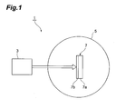
- Fig. 1 is a schematic configuration diagram showing a structure of a nuclear fusion device 1 according to a preferred embodiment of the present invention.
- the nuclear fusion device 1 is a device for inducing a nuclear fusion reaction by laser light irradiation to generate neutrons, and includes a laser unit (laser light irradiating section) 3 for irradiating laser light, a vacuum container 5 the interior of which is maintained in a vacuum state, and a nuclear fusion target 7 stored in the vacuum container 5.
- a laser unit laser light irradiating section
- the laser unit 3 is a unit capable of irradiating ultrashort pulsed laser light having a pulse width of approximately 100fs, using as its laser medium, for example, titanium-sapphire crystal, and having a built-in beam splitter section, pulse delay section, beam coupler section, etc. Moreover, the laser unit 3 is arranged so as to be capable of successively irradiating ultrashort pulsed laser light at predetermined time intervals (for example, a few hundred picosecond intervals). The laser unit 3 is disposed so as to irradiate ultrashort pulses toward the nuclear fusion target 7 in the vacuum container 5.
- the nuclear fusion target 7 has a double-layer structure including a target substrate (first target layer) 7a and a thin-film layer (second target layer) 7b stacked on the target substrate 7a, in which the target substrate 7a is supported so as to has its surface on the side of the thin-film layer 7b facing the side of the laser unit 3.
- the target substrate 7a is a solid material in a flat plate shape having a film thickness of a few hundred micrometers to approximately 1mm containing deuterium or tritium, and for which hydrogen in the solid material has been substituted with deuterium or tritium.
- deuterium substituted polystyrene (C 8 D 8 ) x for which hydrogen in an organic material containing carbon and hydrogen such as plastic represented by polystyrene (C 8 D 8 ) x has been substituted with deuterium is used.
- the thin-film layer 7b to be stacked on the target substrate 7a having the above-described composition is a metal thin film having a film thickness of 1 ⁇ m or less thinner than the target substrate 7a, containing deuterium or tritium, and prepared by making a metal thin film absorb deuterium or tritium.
- a heavy metal such as titanium or palladium that easily absorbs hydrogen is used, and the thin-film layer 7b is formed by vapor-depositing such heavy metal on the target substrate 7a with a film thickness of a few nanometers to a few tens of nanometers and then making the same absorb deuterium.
- the target substrate 7a and the thin-film layer 7b may contain either deuterium or tritium, and may contain both at an appropriate rate.
- the nuclear fusion device 1 is prepared, the nuclear fusion target 7 is disposed in the vacuum container 5 so as to make the thin-film layer 7b face in a laser irradiating direction of the laser unit 3, and then the interior of the vacuum container 5 is vacuumed to a predetermined degree of vacuum.
- a first pulsed laser light having a pulse width of approximately 100fs is irradiated from the laser unit 3 onto the thin-film layer 7b of the nuclear fusion target 7.
- a second pulsed laser light having a pulse width of approximately 100fs to 1ps is irradiated from the laser unit 3 onto the thin-film layer 7b of the nuclear fusion target 7.
- the second pulsed laser light may include a laser prepulse to generate preplasma.
- the intensity of the first pulsed laser light is set to a value on the order of 10 15 W/cm 2 and the intensity of the second pulsed laser light is set to a value on the order of 10 18 W/cm 2 , and the intensity of the first pulsed laser light is made sufficiently smaller than the intensity of the second pulsed laser light.
- the intensity of the first pulsed laser light is set to such an intensity as to cause peeling of the thin-film layer 7b from the target substrate 7a and not to plasmatize the material of the thin-film layer 7b.
- the time interval between the first pulsed laser light and the second pulsed laser light is set to a few hundred picoseconds as such a value that the thin-film layer 7b is peeled from the target substrate 7a to fly approximately a distance of 1 to 10 ⁇ m.
- "two successive pulsed lights” means two pulsed lights having such a time interval that the thin-film layer 7b is peeled from the target substrate 7a to fly approximately a distance of 1 to 10 ⁇ m.
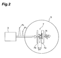
- Fig. 2 is a conceptual diagram showing an induced state of a nuclear fusion reaction in the nuclear fusion device 1.
- the irradiation timing of the second pulsed laser light P 2 is preferably a timing where the distance D1 has reached 1 ⁇ m or more for sufficient acceleration of deuterium ions, and is preferably a timing where the distance D1 has reached 10 ⁇ m or less so as not to reduce the density of deuterium ions reaching the target substrate 7a as a result of diffusion of deuterium ions.
- the nuclear fusion device 1 and nuclear fusion method using the same described in the above by disposing the nuclear fusion target 7 including two layers of the target substrate 7a and thin-film layer 7b containing deuterium or tritium in the vacuum container 5, and irradiating a first pulsed laser light toward the thin-film layer 7b, the thin-film layer 7b can be peeled from the target substrate 7a.
- an ion beam produced from the thin-film layer 7b can be sufficiently accelerated toward the target substrate 7a distant at a predetermined distance, so that a high-energy ion beam can be irradiated onto the target substrate 7a.
- a nuclear fusion reaction can be produced at a high efficiency inside of the target substrate 7a, and the production efficiency of neutrons in response to the nuclear fusion reaction is also improved.
- an ion beam having directionality is made to collide against a target with sufficient acceleration to induce nuclear fusion, and thus in the case of a low laser energy condition, more neutrons can be produced relative to the input energy than by conventional thermonuclear fusion using laser light, so that a high energy efficiency can be achieved.
- the target substrate 7a is one for which hydrogen in a solid material containing hydrogen has been substituted with deuterium or tritium, and thus the disposing structure of the target substrate 7a in the vacuum container 5 is simplified, and stacking of the thin-film layer 7b onto the target substrate 7a also becomes easy.
- the thin-film layer 7b is a metal thin film absorbed with deuterium or tritium, and thus the stacking process onto the target substrate 7a becomes easy. Therefore, the manufacturing process of the nuclear fusion target 7 and the integration process thereof into the nuclear fusion device 1 are in whole simplified.
- the present invention is not limited to the foregoing embodiment.
- Other materials can also be used as the materials of the nuclear fusion target 7.
- a heavy water block for which heavy water (D 2 O or T 2 O) has been frozen and solidified may be used as the target substrate 7a.
- the thin-film layer 7b is formed by vapor deposition in an environment where the temperature is sufficiently controlled so as not to melt the heavy water.
- irradiation with laser light for inducing nuclear fusion is also performed in the same temperature-controlled environment.
- the thin-film layer 7b one for which hydrogen in a solid material has been substituted with deuterium or tritium, such as deuterium substituted polystyrene (C 8 D 8 ) x in a thin film shape, is used, and the target substrate 7a on which the thin film is stacked may also be used.
- deuterium substituted polystyrene C 8 D 8
- an ion accelerator can also be realized.
- the ion accelerator is the same in basic configuration as the nuclear fusion device 1, and is different only in the component of the target substrate 7a of the nuclear fusion target 7.
- a film-like member not containing deuterium or tritium for example, an organic film having a film thickness of approximately 10 ⁇ m is used, and the organic film on which the thin-film layer 7b being deuterium absorbed titanium has been stacked is used as a target.
- a film-like member not containing deuterium or tritium for example, an organic film having a film thickness of approximately 10 ⁇ m is used, and the organic film on which the thin-film layer 7b being deuterium absorbed titanium has been stacked is used as a target.
- the first target layer is a layer for which hydrogen in a solid material containing hydrogen has been substituted with deuterium or tritium.
- the disposing structure of the first target layer is simplified, and stacking of the second target layer also becomes easy.
- the second target layer is a metal thin film absorbed with deuterium or tritium. Adopting such an arrangement makes the stacking process onto the first target layer easy.
- the second target layer is a layer for which hydrogen in a solid material containing hydrogen has been substituted with deuterium or tritium. Adopting such an arrangement makes the stacking process of the second target layer onto the first target layer easy.
- the present invention is used for applications of a nuclear fusion target, nuclear fusion device, and nuclear fusion method using laser light, and is capable of inducing a nuclear fusion reaction at a relatively high efficiency and allows downsizing of the device.
- 1 - Nuclear fusion device 3 - Laser unit (laser light irradiating section), 5 - Vacuum container, 7 - Nuclear fusion target, 7a - Target substrate (first target layer), 7b - Thin-film layer (second target layer), P 1 - First pulsed laser light (first pulsed light), P 2 - Second pulsed laser light (second pulsed light).
Landscapes
- Physics & Mathematics (AREA)
- Engineering & Computer Science (AREA)
- Plasma & Fusion (AREA)
- High Energy & Nuclear Physics (AREA)
- General Engineering & Computer Science (AREA)
- Chemical & Material Sciences (AREA)
- Chemical Kinetics & Catalysis (AREA)
- Optics & Photonics (AREA)
- Spectroscopy & Molecular Physics (AREA)
- Physical Vapour Deposition (AREA)
- Particle Accelerators (AREA)
- Physical Or Chemical Processes And Apparatus (AREA)
Abstract
Description
- The present invention relates to a nuclear fusion target, nuclear fusion device, and nuclear fusion method using laser light.
- Conventionally, it has been studied to use laser light in order to produce nuclear fusion in a highly controlled manner by using a small-sized and low-cost device. Further, through recent research, a great improvement in neutron production efficiency by a nuclear fusion reaction using a laser unit has been expected, and such a neutron production method using a nuclear fusion reaction has come to be expected as a safer method than by a nuclear fission reaction.
- As conventional examples of nuclear fusion production methods using laser light, ones of the following non-patent document 1 and the following patent document 1 have been known. In the method described in the following patent document 1, an irradiation member prepared by coating deuterium substituted plastic on a thin film of Mylar or the like is momentarily irradiated with laser light to produce high-energy hydrogen nuclei, and a target member disposed at approximately a predetermined distance from the irradiation member is irradiated with the hydrogen nuclei to induce a nuclear fusion reaction. On the other hand, in the method described in the following non-patent document 1, two laser pulses are successively made incident at a predetermined time interval (300psec) onto a target prepared by forming a film of deuterium substituted polyethylene (C2D4)X on an aluminum plate to induce a nuclear fusion reaction.
- Patent Document 1: Japanese Patent Application Laid-Open No.
2002-107494 - G. Pretzler et al., "Neutron production by 200 mJ ultrashort laserpulses," Physical Review E, Volume 58, Number 1, The American Physical Society, July 1998, p.1165-1168
- However, the nuclear fusion production method described in non-patent document 1 above, in which the target is plasmatized by the first laser pulse of the two laser pulses, and then ions in the plasma are heated to a high temperature by the second laser pulse to induce thermonuclear fusion, thus requires laser light of a relatively large energy for making the ion density in the plasma an optimum value to produce a thermonuclear fusion reaction efficiently. Moreover, in the nuclear fusion production method described in patent document 1 above, the energy efficiency is not sufficiently obtained. As a result, there is a tendency in both methods that it is difficult to produce a nuclear fusion reaction at a high energy efficiency.
- Therefore, the present invention has been made in view of such problems, and an object thereof is to provide a nuclear fusion target, nuclear fusion device, and nuclear fusion method that is capable of inducing a nuclear fusion reaction at a relatively high efficiency, and that allows downsizing of the device.
- In order to solve the above-described problems, a nuclear fusion target of the present invention is a nuclear fusion target for producing a nuclear fusion reaction by irradiating laser light, and includes a first target layer having a first film thickness containing deuterium or tritium, and a second target layer having a second film thickness thinner than the first film thickness stacked on the first target layer and containing deuterium or tritium.
- Alternatively, a nuclear fusion device of the present invention includes the nuclear fusion target described above, a vacuum container for storing the nuclear fusion target, and a laser light irradiating section for irradiating laser light including two successive first and second pulsed lights toward the second target layer of the nuclear fusion target, and the intensity of the first pulsed light is set to a value that is smaller than that of the second pulsed light and allows peeling of the second target layer from the first target layer.
- Alternatively, a nuclear fusion method of the present invention is a nuclear fusion method for producing a nuclear fusion reaction by irradiating laser light, and includes a step of disposing in a vacuum a nuclear fusion target including a first target layer having a first film thickness containing deuterium or tritium, and a second target layer having a second film thickness thinner than the first film thickness stacked on the first target layer and containing deuterium or tritium, and a step of irradiating laser light including two successive first and second pulsed lights toward the second target layer of the nuclear fusion target, and the intensity of the first pulsed light is set to a value that is smaller than that of the second pulsed light and allows peeling of the second target layer from the first target layer.
- According to such a nuclear fusion target, nuclear fusion device, or nuclear fusion method, by disposing the nuclear fusion target including two layers of first and second target layers containing deuterium or tritium in a vacuum, and irradiating a first pulsed light toward the second target layer being a thin-film layer, the second target layer can be peeled from the first target layer. Thereafter, by irradiating a second pulsed light following the first pulsed light onto the second target layer with a predetermined time interval, an ion beam produced from the first target layer can be sufficiently accelerated toward the second target layer distant at a predetermined distance, so that a high-energy ion beam can be irradiated onto the first target layer. As a result, a nuclear fusion reaction can be produced at a high efficiency in the vicinity of the first target layer, and the production efficiency of neutrons is also improved. Simultaneously, adopting the target including the two target layers also makes downsizing of the device easy.
- According to the present invention, a nuclear fusion reaction can be induced at a relatively high efficiency, and the device can be downsized.
-
-
Fig. 1 is a schematic configuration diagram showing a structure of a nuclear fusion device 1 according to a preferred embodiment of the present invention. -
Fig. 2 is a conceptual diagram showing an induced state of a nuclear fusion reaction in the nuclear fusion device ofFig. 1 . - Hereinafter, a preferred embodiment of a nuclear fusion device and nuclear fusion method according to the present invention will be described in detail with reference to the drawings. In the description of the drawings, the portions identical to or equivalent to each other are denoted by the same reference numerals and overlapping description will be omitted. The drawings are prepared for description, and are drawn so that the parts to be described are especially emphasized. Therefore, the dimensional ratios of the members in the drawings are not always coincident with actual ratios.
-
Fig. 1 is a schematic configuration diagram showing a structure of a nuclear fusion device 1 according to a preferred embodiment of the present invention. The nuclear fusion device 1 is a device for inducing a nuclear fusion reaction by laser light irradiation to generate neutrons, and includes a laser unit (laser light irradiating section) 3 for irradiating laser light, avacuum container 5 the interior of which is maintained in a vacuum state, and anuclear fusion target 7 stored in thevacuum container 5. - The
laser unit 3 is a unit capable of irradiating ultrashort pulsed laser light having a pulse width of approximately 100fs, using as its laser medium, for example, titanium-sapphire crystal, and having a built-in beam splitter section, pulse delay section, beam coupler section, etc. Moreover, thelaser unit 3 is arranged so as to be capable of successively irradiating ultrashort pulsed laser light at predetermined time intervals (for example, a few hundred picosecond intervals). Thelaser unit 3 is disposed so as to irradiate ultrashort pulses toward thenuclear fusion target 7 in thevacuum container 5. - The
nuclear fusion target 7 has a double-layer structure including a target substrate (first target layer) 7a and a thin-film layer (second target layer) 7b stacked on thetarget substrate 7a, in which thetarget substrate 7a is supported so as to has its surface on the side of the thin-film layer 7b facing the side of thelaser unit 3. - The
target substrate 7a is a solid material in a flat plate shape having a film thickness of a few hundred micrometers to approximately 1mm containing deuterium or tritium, and for which hydrogen in the solid material has been substituted with deuterium or tritium. For example, as the material of thetarget substrate 7a, deuterium substituted polystyrene (C8D8)x for which hydrogen in an organic material containing carbon and hydrogen such as plastic represented by polystyrene (C8D8)x has been substituted with deuterium is used. - The thin-
film layer 7b to be stacked on thetarget substrate 7a having the above-described composition is a metal thin film having a film thickness of 1µm or less thinner than thetarget substrate 7a, containing deuterium or tritium, and prepared by making a metal thin film absorb deuterium or tritium. For example, as the thin-film layer 7b, a heavy metal such as titanium or palladium that easily absorbs hydrogen is used, and the thin-film layer 7b is formed by vapor-depositing such heavy metal on thetarget substrate 7a with a film thickness of a few nanometers to a few tens of nanometers and then making the same absorb deuterium. - Here, the
target substrate 7a and the thin-film layer 7b may contain either deuterium or tritium, and may contain both at an appropriate rate. - Next, the procedure for inducing a nuclear fusion reaction in the nuclear fusion device 1 described above will be described in greater detail, and a nuclear fusion method using laser light according to the present embodiment will be described.
- First, the nuclear fusion device 1 is prepared, the
nuclear fusion target 7 is disposed in thevacuum container 5 so as to make the thin-film layer 7b face in a laser irradiating direction of thelaser unit 3, and then the interior of thevacuum container 5 is vacuumed to a predetermined degree of vacuum. - Thereafter, a first pulsed laser light having a pulse width of approximately 100fs is irradiated from the
laser unit 3 onto the thin-film layer 7b of thenuclear fusion target 7. Further, shortly thereafter, following the first pulsed laser light with a predetermined time interval, a second pulsed laser light having a pulse width of approximately 100fs to 1ps is irradiated from thelaser unit 3 onto the thin-film layer 7b of thenuclear fusion target 7. Here, the second pulsed laser light may include a laser prepulse to generate preplasma. - At this time, the intensity of the first pulsed laser light is set to a value on the order of 1015W/cm2 and the intensity of the second pulsed laser light is set to a value on the order of 1018W/cm2, and the intensity of the first pulsed laser light is made sufficiently smaller than the intensity of the second pulsed laser light. The intensity of the first pulsed laser light is set to such an intensity as to cause peeling of the thin-
film layer 7b from thetarget substrate 7a and not to plasmatize the material of the thin-film layer 7b. Moreover, the time interval between the first pulsed laser light and the second pulsed laser light is set to a few hundred picoseconds as such a value that the thin-film layer 7b is peeled from thetarget substrate 7a to fly approximately a distance of 1 to 10µm. Specifically, in the present specification, "two successive pulsed lights" means two pulsed lights having such a time interval that the thin-film layer 7b is peeled from thetarget substrate 7a to fly approximately a distance of 1 to 10µm. -
Fig. 2 is a conceptual diagram showing an induced state of a nuclear fusion reaction in the nuclear fusion device 1. By setting the intensities and time interval of the first pulsed laser light P1 and the second pulsed laser light P2 as in the above, the thin-film layer 7b is peeled from thetarget substrate 7a shortly after irradiation with the first pulsed laser light P1, and the second pulsed layer light P2 is thereafter irradiated onto the thin-film layer 7b at a timing where the distance D1 between the thin-film layer 7b and thetarget substrate 7a has reached approximately 1 to 10µm. As a result, in response to the irradiation of the second pulsed laser light P2 onto the thin-film layer 7b, deuterium ions I are generated in the thin-film layer 7b, and the deuterium ions I are sufficiently accelerated between the thin-film layer 7b and thetarget substrate 7a to collide against thetarget substrate 7a. In response thereto, a D-D nuclear fusion reaction is induced between deuterium inside thetarget substrate 7a and the ions I, and neutrons N generated accordingly are emitted toward the outside of thevacuum container 5. - In addition, the irradiation timing of the second pulsed laser light P2 is preferably a timing where the distance D1 has reached 1µm or more for sufficient acceleration of deuterium ions, and is preferably a timing where the distance D1 has reached 10µm or less so as not to reduce the density of deuterium ions reaching the
target substrate 7a as a result of diffusion of deuterium ions. - According to the nuclear fusion device 1 and nuclear fusion method using the same described in the above, by disposing the
nuclear fusion target 7 including two layers of thetarget substrate 7a and thin-film layer 7b containing deuterium or tritium in thevacuum container 5, and irradiating a first pulsed laser light toward the thin-film layer 7b, the thin-film layer 7b can be peeled from thetarget substrate 7a. Thereafter, by irradiating a second pulsed laser light following the first pulsed laser light onto the thin-film layer 7b with a predetermined time interval, an ion beam produced from the thin-film layer 7b can be sufficiently accelerated toward thetarget substrate 7a distant at a predetermined distance, so that a high-energy ion beam can be irradiated onto thetarget substrate 7a. As a result, a nuclear fusion reaction can be produced at a high efficiency inside of thetarget substrate 7a, and the production efficiency of neutrons in response to the nuclear fusion reaction is also improved. Simultaneously, as a result of adopting the arrangement of thenuclear fusion target 7 consisting of two layers being disposed in thevacuum container 5, a conventionally used large-scale accelerator and nuclear reactor are no longer necessary, so that downsizing of the device also becomes easy. - In particular, according to the present embodiment, an ion beam having directionality is made to collide against a target with sufficient acceleration to induce nuclear fusion, and thus in the case of a low laser energy condition, more neutrons can be produced relative to the input energy than by conventional thermonuclear fusion using laser light, so that a high energy efficiency can be achieved.
- Here, the
target substrate 7a is one for which hydrogen in a solid material containing hydrogen has been substituted with deuterium or tritium, and thus the disposing structure of thetarget substrate 7a in thevacuum container 5 is simplified, and stacking of the thin-film layer 7b onto thetarget substrate 7a also becomes easy. Further, the thin-film layer 7b is a metal thin film absorbed with deuterium or tritium, and thus the stacking process onto thetarget substrate 7a becomes easy. Therefore, the manufacturing process of thenuclear fusion target 7 and the integration process thereof into the nuclear fusion device 1 are in whole simplified. - In addition, the present invention is not limited to the foregoing embodiment. Other materials can also be used as the materials of the
nuclear fusion target 7. - For example, as the
target substrate 7a, a heavy water block for which heavy water (D2O or T2O) has been frozen and solidified may be used. In this case, when forming the thin-film layer 7b, the thin-film layer 7b is formed by vapor deposition in an environment where the temperature is sufficiently controlled so as not to melt the heavy water. Moreover, irradiation with laser light for inducing nuclear fusion is also performed in the same temperature-controlled environment. - On the other hand, as the thin-
film layer 7b, one for which hydrogen in a solid material has been substituted with deuterium or tritium, such as deuterium substituted polystyrene (C8D8)x in a thin film shape, is used, and thetarget substrate 7a on which the thin film is stacked may also be used. - Moreover, as a modification of the present embodiment, an ion accelerator can also be realized. The ion accelerator is the same in basic configuration as the nuclear fusion device 1, and is different only in the component of the
target substrate 7a of thenuclear fusion target 7. Specifically, as the material of thetarget substrate 7a, a film-like member not containing deuterium or tritium, for example, an organic film having a film thickness of approximately 10µm is used, and the organic film on which the thin-film layer 7b being deuterium absorbed titanium has been stacked is used as a target. According to such an ion accelerator, by irradiating the target with double pulsed laser light containing a first pulsed laser light and a second pulsed laser light, accelerated ions from the thin-film layer 7b toward the outside can be produced. - Here, it is preferable that the first target layer is a layer for which hydrogen in a solid material containing hydrogen has been substituted with deuterium or tritium. In this case, the disposing structure of the first target layer is simplified, and stacking of the second target layer also becomes easy.
- Moreover, it is also preferable that the second target layer is a metal thin film absorbed with deuterium or tritium. Adopting such an arrangement makes the stacking process onto the first target layer easy.
- Further, it is also preferable that the second target layer is a layer for which hydrogen in a solid material containing hydrogen has been substituted with deuterium or tritium. Adopting such an arrangement makes the stacking process of the second target layer onto the first target layer easy.
- The present invention is used for applications of a nuclear fusion target, nuclear fusion device, and nuclear fusion method using laser light, and is capable of inducing a nuclear fusion reaction at a relatively high efficiency and allows downsizing of the device.
- 1 - Nuclear fusion device, 3 - Laser unit (laser light irradiating section), 5 - Vacuum container, 7 - Nuclear fusion target, 7a - Target substrate (first target layer), 7b - Thin-film layer (second target layer), P1 - First pulsed laser light (first pulsed light), P2 - Second pulsed laser light (second pulsed light).
Claims (6)
- A nuclear fusion target for producing a nuclear fusion reaction, comprising:a first target layer having a first film thickness containing deuterium or tritium; anda second target layer having a second film thickness thinner than the first film thickness stacked on the first target layer and containing deuterium or tritium.
- The nuclear fusion target according to claim 1, wherein
the first target layer is a layer for which hydrogen in a solid material containing hydrogen has been substituted with deuterium or tritium. - The nuclear fusion target according to claim 1 or 2, wherein
the second target layer is a metal thin film absorbed with deuterium or tritium. - The nuclear fusion target according to claim 1 or 2, wherein
the second target layer is a layer for which hydrogen in a solid material containing hydrogen has been substituted with deuterium or tritium. - A nuclear fusion device comprising:the nuclear fusion target according to any one of claims 1 to 4;a vacuum container for storing the nuclear fusion target; anda laser light irradiating section for irradiating laser light including two successive first and second pulsed lights toward the second target layer of the nuclear fusion target, whereinthe intensity of the first pulsed light is set to a value that is smaller than that of the second pulsed light and allows peeling of the second target layer from the first target layer.
- A nuclear fusion method for producing a nuclear fusion reaction comprising the steps of:disposing in a vacuum a nuclear fusion target including a first target layer having a first film thickness containing deuterium or tritium, and a second target layer having a second film thickness thinner than the first film thickness stacked on the first target layer and containing deuterium or tritium; andirradiating laser light including two successive first and second pulsed lights toward the second target layer of the nuclear fusion target, whereinthe intensity of the first pulsed light is set to a value that is smaller than that of the second pulsed light and allows peeling of the second target layer from the first target layer.
Applications Claiming Priority (2)
| Application Number | Priority Date | Filing Date | Title |
|---|---|---|---|
| JP2009285383A JP5629089B2 (en) | 2009-12-16 | 2009-12-16 | Fusion target material, fusion device, and fusion method |
| PCT/JP2010/072573 WO2011074612A1 (en) | 2009-12-16 | 2010-12-15 | Nuclear fusion target, nuclear fusion device, and nuclear fusion method |
Publications (3)
| Publication Number | Publication Date |
|---|---|
| EP2515308A1 true EP2515308A1 (en) | 2012-10-24 |
| EP2515308A4 EP2515308A4 (en) | 2016-02-10 |
| EP2515308B1 EP2515308B1 (en) | 2018-02-07 |
Family
ID=44167364
Family Applications (1)
| Application Number | Title | Priority Date | Filing Date |
|---|---|---|---|
| EP10837638.5A Not-in-force EP2515308B1 (en) | 2009-12-16 | 2010-12-15 | Nuclear fusion target, nuclear fusion device, and nuclear fusion method |
Country Status (6)
| Country | Link |
|---|---|
| US (1) | US9363882B2 (en) |
| EP (1) | EP2515308B1 (en) |
| JP (1) | JP5629089B2 (en) |
| KR (1) | KR101705271B1 (en) |
| CN (1) | CN102714062B (en) |
| WO (1) | WO2011074612A1 (en) |
Cited By (2)
| Publication number | Priority date | Publication date | Assignee | Title |
|---|---|---|---|---|
| WO2013144482A1 (en) * | 2012-03-27 | 2013-10-03 | Ecole Polytechnique | Production of energy via laser-initiated aneutronic nuclear fusion reactions |
| CZ306319B6 (en) * | 2013-07-30 | 2016-11-30 | Fyzikální Ústav Av Čr, V. V. I. | Fixed target for nuclear fusion, apparatus for making nuclear fusion with this fixed target and method of making nuclear fusion with this apparatus |
Families Citing this family (18)
| Publication number | Priority date | Publication date | Assignee | Title |
|---|---|---|---|---|
| KR101269098B1 (en) | 2011-12-23 | 2013-05-29 | 한국원자력연구원 | Double-layer target with a narrow vacuum gap for the laser induced particle acceleration |
| JP5986476B2 (en) * | 2012-10-16 | 2016-09-06 | 浜松ホトニクス株式会社 | Laser fusion apparatus and fusion generation method |
| WO2014133623A2 (en) * | 2012-12-13 | 2014-09-04 | Lawrence Livermore National Security, Llc | Fusion target projectile accelerator |
| FR3008822B1 (en) * | 2013-07-22 | 2015-09-18 | Ecole Polytech | CREATION OF ISOTOPES BY LASER BEAMS |
| KR101623152B1 (en) | 2013-12-31 | 2016-05-23 | 한국원자력연구원 | Film target for laser induced particle acceleration and manufacturing method thereof |
| CA3007442A1 (en) * | 2015-12-04 | 2017-07-27 | Ih Ip Holdings Limited | Methods and apparatus for triggering exothermic reactions |
| WO2018118053A1 (en) * | 2016-12-21 | 2018-06-28 | Halliburton Energy Services, Inc. | Downhole neutron generators and methods to generate neutrons in a downhole environment |
| CN108877960A (en) * | 2017-05-15 | 2018-11-23 | 陈鹏玮 | ICF freezes target assembly and ICF shielding case opening speed best practice |
| US10462893B2 (en) | 2017-06-05 | 2019-10-29 | Neutron Therapeutics, Inc. | Method and system for surface modification of substrate for ion beam target |
| JP7319252B2 (en) * | 2017-06-05 | 2023-08-01 | ニュートロン・セラピューティクス・インコーポレイテッド | Method and system for surface modification of substrates for ion beam targets |
| US12555692B2 (en) * | 2017-08-16 | 2026-02-17 | Innoven Energy Llc | Reflectivity variation of ICF target surfaces |
| RU2687289C1 (en) * | 2017-11-23 | 2019-05-13 | Российская Федерация, от имени которой выступает Государственная корпорация по атомной энергии "Росатом" | Device for attachment of blanket module on vacuum housing of thermonuclear reactor |
| CN109326963B (en) * | 2018-10-11 | 2020-05-08 | 陈红婷 | Free electron energy regulator |
| CN111050457A (en) * | 2019-12-27 | 2020-04-21 | 西京学院 | Device and method for improving neutron yield based on laser-induced plasma |
| CN112851990B (en) * | 2020-12-31 | 2022-01-28 | 中国工程物理研究院激光聚变研究中心 | Method for preparing film-foam dual-medium modulation target by casting compound |
| RU203062U1 (en) * | 2021-01-11 | 2021-03-22 | Российская Федерация, от имени которой выступает Государственная корпорация по атомной энергии "Росатом" | Device for fastening the blanket module on the vacuum vessel of a thermonuclear reactor |
| CN114566296A (en) * | 2022-03-31 | 2022-05-31 | 戴文韬 | Hydrogen, deuterium and tritium alloy reactor nuclear fusion method and device |
| CN118335361A (en) * | 2024-05-17 | 2024-07-12 | 戴文韬 | A hydrogen-deuterium-tritium alloy reactor nuclear fusion system with fuel addition and reaction cycle |
Family Cites Families (13)
| Publication number | Priority date | Publication date | Assignee | Title |
|---|---|---|---|---|
| US2847331A (en) * | 1954-12-24 | 1958-08-12 | Robert W Ashley | Hydrogen isotope targets |
| FR1584364A (en) * | 1968-08-08 | 1969-12-19 | ||
| US3716491A (en) | 1969-07-09 | 1973-02-13 | L Yannopoulos | Yttrium-hydrogen isotope compositions for radiochemical reactions |
| JPS5124496A (en) * | 1974-08-24 | 1976-02-27 | Makoto Imamura | |
| JPS61139787A (en) * | 1984-12-13 | 1986-06-27 | 株式会社東芝 | Fuel pellet for inertial confinement nuclear fusion |
| JPS62280685A (en) * | 1986-05-29 | 1987-12-05 | 株式会社東芝 | Fuel pellet for inertial confinement nuclear fusion |
| JPH10253785A (en) | 1997-03-12 | 1998-09-25 | Laser Gijutsu Sogo Kenkyusho | Method and apparatus for generation of nuclear fusion reaction |
| WO1999056521A2 (en) | 1998-05-06 | 1999-11-11 | American Technologies Group, Inc. | Method and apparatus for the production of neutrons and other particles |
| JP4913938B2 (en) | 2000-09-27 | 2012-04-11 | 財団法人電力中央研究所 | Nuclear reaction induction method and nuclear reaction induction device |
| CA2325362A1 (en) | 2000-11-08 | 2002-05-08 | Kirk Flippo | Method and apparatus for high-energy generation and for inducing nuclear reactions |
| JP4116425B2 (en) * | 2002-12-27 | 2008-07-09 | 浜松ホトニクス株式会社 | Deuteron generation target and deuteron generation target device |
| CN101529998A (en) * | 2006-08-18 | 2009-09-09 | 统一重力股份有限公司 | Hydrogen-lithium fusion device, method and applications |
| CN101377962B (en) * | 2008-09-22 | 2012-07-04 | 中国科学院等离子体物理研究所 | Fusion driven subcritical systems and methods for producing 252Cf neutron sources |
-
2009
- 2009-12-16 JP JP2009285383A patent/JP5629089B2/en active Active
-
2010
- 2010-12-15 US US13/516,112 patent/US9363882B2/en not_active Expired - Fee Related
- 2010-12-15 EP EP10837638.5A patent/EP2515308B1/en not_active Not-in-force
- 2010-12-15 WO PCT/JP2010/072573 patent/WO2011074612A1/en not_active Ceased
- 2010-12-15 KR KR1020127014510A patent/KR101705271B1/en not_active Expired - Fee Related
- 2010-12-15 CN CN201080057004.3A patent/CN102714062B/en not_active Expired - Fee Related
Non-Patent Citations (1)
| Title |
|---|
| See references of WO2011074612A1 * |
Cited By (2)
| Publication number | Priority date | Publication date | Assignee | Title |
|---|---|---|---|---|
| WO2013144482A1 (en) * | 2012-03-27 | 2013-10-03 | Ecole Polytechnique | Production of energy via laser-initiated aneutronic nuclear fusion reactions |
| CZ306319B6 (en) * | 2013-07-30 | 2016-11-30 | Fyzikální Ústav Av Čr, V. V. I. | Fixed target for nuclear fusion, apparatus for making nuclear fusion with this fixed target and method of making nuclear fusion with this apparatus |
Also Published As
| Publication number | Publication date |
|---|---|
| EP2515308B1 (en) | 2018-02-07 |
| WO2011074612A1 (en) | 2011-06-23 |
| CN102714062B (en) | 2015-04-01 |
| US9363882B2 (en) | 2016-06-07 |
| JP2011127968A (en) | 2011-06-30 |
| CN102714062A (en) | 2012-10-03 |
| EP2515308A4 (en) | 2016-02-10 |
| JP5629089B2 (en) | 2014-11-19 |
| KR101705271B1 (en) | 2017-02-22 |
| US20120307950A1 (en) | 2012-12-06 |
| KR20120107471A (en) | 2012-10-02 |
Similar Documents
| Publication | Publication Date | Title |
|---|---|---|
| EP2515308B1 (en) | Nuclear fusion target, nuclear fusion device, and nuclear fusion method | |
| Curtis et al. | Micro-scale fusion in dense relativistic nanowire array plasmas | |
| Picciotto et al. | Boron-proton nuclear-fusion enhancement induced in boron-doped silicon targets by low-contrast pulsed laser | |
| Lindl et al. | Progress toward ignition and burn propagation in inertial confinement fusion | |
| Xu et al. | Probing laser-induced plasma generation in liquid water | |
| Shou et al. | High-efficiency water-window x-ray generation from nanowire array targets irradiated with femtosecond laser pulses | |
| Wang et al. | Ultrafast imaging for uncovering laser–material interaction dynamics | |
| Fedeli et al. | Structured targets for advanced laser-driven sources | |
| Jiang et al. | Direct acceleration of an annular attosecond electron slice driven by near-infrared Laguerre–Gaussian laser | |
| Kong et al. | Alpha-particle generation from H-11B fusion initiated by laser-accelerated boron ions | |
| Petrov et al. | Proton acceleration from high-contrast short pulse lasers interacting with sub-micron thin foils | |
| Lebo et al. | Two-sided conical laser target for a neutron source of a hybrid nuclear-thermonuclear reactor | |
| Wang et al. | Hollow pellet injection for magnetic fusion | |
| Zylstra et al. | IFE Science & Technology Community Strategic Planning Workshop Report | |
| CN119789294B (en) | Conversion body for laser beam target neutron source and optimal design method thereof | |
| Hauer et al. | Current new applications of laser plasmas | |
| Yuan et al. | Optimization of x-ray emission from triple-foil target irradiated with counter-propagate laser | |
| Limpouch et al. | Laser ion acceleration: from present to intensities achievable at ELI-Beamlines | |
| Blazevic et al. | High energy density matter generated by heavy-ion beams, and application to fusion energy | |
| Fortov | High-power lasers in high-energy-density physics | |
| Maffini et al. | Nanofoam in action: a versatile tool for laser-plasma interaction experiments | |
| Qiu et al. | Plasma dynamics in transient electrostatic shocks driven by relativistic few-cycle laser pulses | |
| Tochitsky et al. | Summary report of working group 6: Laser-plasma acceleration of ions | |
| Vavassori | Production of optimized targets for enhanced laser-driven ion acceleration | |
| Fortov | Laser-Driven Shock Waves |
Legal Events
| Date | Code | Title | Description |
|---|---|---|---|
| PUAI | Public reference made under article 153(3) epc to a published international application that has entered the european phase |
Free format text: ORIGINAL CODE: 0009012 |
|
| 17P | Request for examination filed |
Effective date: 20120702 |
|
| AK | Designated contracting states |
Kind code of ref document: A1 Designated state(s): AL AT BE BG CH CY CZ DE DK EE ES FI FR GB GR HR HU IE IS IT LI LT LU LV MC MK MT NL NO PL PT RO RS SE SI SK SM TR |
|
| RAP1 | Party data changed (applicant data changed or rights of an application transferred) |
Owner name: TOYOTA JIDOSHA KABUSHIKI KAISHA Owner name: HAMAMATSU PHOTONICS K.K. |
|
| DAX | Request for extension of the european patent (deleted) | ||
| REG | Reference to a national code |
Ref country code: DE Ref legal event code: R079 Ref document number: 602010048433 Country of ref document: DE Free format text: PREVIOUS MAIN CLASS: G21B0001150000 Ipc: G21B0003000000 |
|
| RIC1 | Information provided on ipc code assigned before grant |
Ipc: H05H 6/00 20060101ALI20151222BHEP Ipc: G21B 3/00 20060101AFI20151222BHEP |
|
| RA4 | Supplementary search report drawn up and despatched (corrected) |
Effective date: 20160113 |
|
| GRAP | Despatch of communication of intention to grant a patent |
Free format text: ORIGINAL CODE: EPIDOSNIGR1 |
|
| STAA | Information on the status of an ep patent application or granted ep patent |
Free format text: STATUS: GRANT OF PATENT IS INTENDED |
|
| INTG | Intention to grant announced |
Effective date: 20170803 |
|
| GRAS | Grant fee paid |
Free format text: ORIGINAL CODE: EPIDOSNIGR3 |
|
| GRAA | (expected) grant |
Free format text: ORIGINAL CODE: 0009210 |
|
| STAA | Information on the status of an ep patent application or granted ep patent |
Free format text: STATUS: THE PATENT HAS BEEN GRANTED |
|
| AK | Designated contracting states |
Kind code of ref document: B1 Designated state(s): AL AT BE BG CH CY CZ DE DK EE ES FI FR GB GR HR HU IE IS IT LI LT LU LV MC MK MT NL NO PL PT RO RS SE SI SK SM TR |
|
| REG | Reference to a national code |
Ref country code: GB Ref legal event code: FG4D |
|
| REG | Reference to a national code |
Ref country code: AT Ref legal event code: REF Ref document number: 969084 Country of ref document: AT Kind code of ref document: T Effective date: 20180215 Ref country code: CH Ref legal event code: EP |
|
| REG | Reference to a national code |
Ref country code: IE Ref legal event code: FG4D |
|
| REG | Reference to a national code |
Ref country code: DE Ref legal event code: R096 Ref document number: 602010048433 Country of ref document: DE |
|
| REG | Reference to a national code |
Ref country code: NL Ref legal event code: MP Effective date: 20180207 |
|
| REG | Reference to a national code |
Ref country code: AT Ref legal event code: MK05 Ref document number: 969084 Country of ref document: AT Kind code of ref document: T Effective date: 20180207 |
|
| PG25 | Lapsed in a contracting state [announced via postgrant information from national office to epo] |
Ref country code: HR Free format text: LAPSE BECAUSE OF FAILURE TO SUBMIT A TRANSLATION OF THE DESCRIPTION OR TO PAY THE FEE WITHIN THE PRESCRIBED TIME-LIMIT Effective date: 20180207 Ref country code: LT Free format text: LAPSE BECAUSE OF FAILURE TO SUBMIT A TRANSLATION OF THE DESCRIPTION OR TO PAY THE FEE WITHIN THE PRESCRIBED TIME-LIMIT Effective date: 20180207 Ref country code: CY Free format text: LAPSE BECAUSE OF FAILURE TO SUBMIT A TRANSLATION OF THE DESCRIPTION OR TO PAY THE FEE WITHIN THE PRESCRIBED TIME-LIMIT Effective date: 20180207 Ref country code: FI Free format text: LAPSE BECAUSE OF FAILURE TO SUBMIT A TRANSLATION OF THE DESCRIPTION OR TO PAY THE FEE WITHIN THE PRESCRIBED TIME-LIMIT Effective date: 20180207 Ref country code: NO Free format text: LAPSE BECAUSE OF FAILURE TO SUBMIT A TRANSLATION OF THE DESCRIPTION OR TO PAY THE FEE WITHIN THE PRESCRIBED TIME-LIMIT Effective date: 20180507 Ref country code: ES Free format text: LAPSE BECAUSE OF FAILURE TO SUBMIT A TRANSLATION OF THE DESCRIPTION OR TO PAY THE FEE WITHIN THE PRESCRIBED TIME-LIMIT Effective date: 20180207 Ref country code: NL Free format text: LAPSE BECAUSE OF FAILURE TO SUBMIT A TRANSLATION OF THE DESCRIPTION OR TO PAY THE FEE WITHIN THE PRESCRIBED TIME-LIMIT Effective date: 20180207 |
|
| PG25 | Lapsed in a contracting state [announced via postgrant information from national office to epo] |
Ref country code: AT Free format text: LAPSE BECAUSE OF FAILURE TO SUBMIT A TRANSLATION OF THE DESCRIPTION OR TO PAY THE FEE WITHIN THE PRESCRIBED TIME-LIMIT Effective date: 20180207 Ref country code: SE Free format text: LAPSE BECAUSE OF FAILURE TO SUBMIT A TRANSLATION OF THE DESCRIPTION OR TO PAY THE FEE WITHIN THE PRESCRIBED TIME-LIMIT Effective date: 20180207 Ref country code: LV Free format text: LAPSE BECAUSE OF FAILURE TO SUBMIT A TRANSLATION OF THE DESCRIPTION OR TO PAY THE FEE WITHIN THE PRESCRIBED TIME-LIMIT Effective date: 20180207 Ref country code: RS Free format text: LAPSE BECAUSE OF FAILURE TO SUBMIT A TRANSLATION OF THE DESCRIPTION OR TO PAY THE FEE WITHIN THE PRESCRIBED TIME-LIMIT Effective date: 20180207 Ref country code: PL Free format text: LAPSE BECAUSE OF FAILURE TO SUBMIT A TRANSLATION OF THE DESCRIPTION OR TO PAY THE FEE WITHIN THE PRESCRIBED TIME-LIMIT Effective date: 20180207 Ref country code: GR Free format text: LAPSE BECAUSE OF FAILURE TO SUBMIT A TRANSLATION OF THE DESCRIPTION OR TO PAY THE FEE WITHIN THE PRESCRIBED TIME-LIMIT Effective date: 20180508 Ref country code: IS Free format text: LAPSE BECAUSE OF FAILURE TO SUBMIT A TRANSLATION OF THE DESCRIPTION OR TO PAY THE FEE WITHIN THE PRESCRIBED TIME-LIMIT Effective date: 20180607 Ref country code: BG Free format text: LAPSE BECAUSE OF FAILURE TO SUBMIT A TRANSLATION OF THE DESCRIPTION OR TO PAY THE FEE WITHIN THE PRESCRIBED TIME-LIMIT Effective date: 20180507 |
|
| REG | Reference to a national code |
Ref country code: DE Ref legal event code: R084 Ref document number: 602010048433 Country of ref document: DE |
|
| REG | Reference to a national code |
Ref country code: GB Ref legal event code: 746 Effective date: 20180912 |
|
| PG25 | Lapsed in a contracting state [announced via postgrant information from national office to epo] |
Ref country code: AL Free format text: LAPSE BECAUSE OF FAILURE TO SUBMIT A TRANSLATION OF THE DESCRIPTION OR TO PAY THE FEE WITHIN THE PRESCRIBED TIME-LIMIT Effective date: 20180207 Ref country code: EE Free format text: LAPSE BECAUSE OF FAILURE TO SUBMIT A TRANSLATION OF THE DESCRIPTION OR TO PAY THE FEE WITHIN THE PRESCRIBED TIME-LIMIT Effective date: 20180207 Ref country code: IT Free format text: LAPSE BECAUSE OF FAILURE TO SUBMIT A TRANSLATION OF THE DESCRIPTION OR TO PAY THE FEE WITHIN THE PRESCRIBED TIME-LIMIT Effective date: 20180207 Ref country code: RO Free format text: LAPSE BECAUSE OF FAILURE TO SUBMIT A TRANSLATION OF THE DESCRIPTION OR TO PAY THE FEE WITHIN THE PRESCRIBED TIME-LIMIT Effective date: 20180207 |
|
| REG | Reference to a national code |
Ref country code: DE Ref legal event code: R097 Ref document number: 602010048433 Country of ref document: DE |
|
| PG25 | Lapsed in a contracting state [announced via postgrant information from national office to epo] |
Ref country code: SK Free format text: LAPSE BECAUSE OF FAILURE TO SUBMIT A TRANSLATION OF THE DESCRIPTION OR TO PAY THE FEE WITHIN THE PRESCRIBED TIME-LIMIT Effective date: 20180207 Ref country code: CZ Free format text: LAPSE BECAUSE OF FAILURE TO SUBMIT A TRANSLATION OF THE DESCRIPTION OR TO PAY THE FEE WITHIN THE PRESCRIBED TIME-LIMIT Effective date: 20180207 Ref country code: DK Free format text: LAPSE BECAUSE OF FAILURE TO SUBMIT A TRANSLATION OF THE DESCRIPTION OR TO PAY THE FEE WITHIN THE PRESCRIBED TIME-LIMIT Effective date: 20180207 Ref country code: SM Free format text: LAPSE BECAUSE OF FAILURE TO SUBMIT A TRANSLATION OF THE DESCRIPTION OR TO PAY THE FEE WITHIN THE PRESCRIBED TIME-LIMIT Effective date: 20180207 |
|
| PLBE | No opposition filed within time limit |
Free format text: ORIGINAL CODE: 0009261 |
|
| STAA | Information on the status of an ep patent application or granted ep patent |
Free format text: STATUS: NO OPPOSITION FILED WITHIN TIME LIMIT |
|
| 26N | No opposition filed |
Effective date: 20181108 |
|
| PG25 | Lapsed in a contracting state [announced via postgrant information from national office to epo] |
Ref country code: SI Free format text: LAPSE BECAUSE OF FAILURE TO SUBMIT A TRANSLATION OF THE DESCRIPTION OR TO PAY THE FEE WITHIN THE PRESCRIBED TIME-LIMIT Effective date: 20180207 |
|
| REG | Reference to a national code |
Ref country code: CH Ref legal event code: PL |
|
| PG25 | Lapsed in a contracting state [announced via postgrant information from national office to epo] |
Ref country code: LU Free format text: LAPSE BECAUSE OF NON-PAYMENT OF DUE FEES Effective date: 20181215 Ref country code: MC Free format text: LAPSE BECAUSE OF FAILURE TO SUBMIT A TRANSLATION OF THE DESCRIPTION OR TO PAY THE FEE WITHIN THE PRESCRIBED TIME-LIMIT Effective date: 20180207 |
|
| REG | Reference to a national code |
Ref country code: IE Ref legal event code: MM4A |
|
| REG | Reference to a national code |
Ref country code: BE Ref legal event code: MM Effective date: 20181231 |
|
| PG25 | Lapsed in a contracting state [announced via postgrant information from national office to epo] |
Ref country code: IE Free format text: LAPSE BECAUSE OF NON-PAYMENT OF DUE FEES Effective date: 20181215 |
|
| PG25 | Lapsed in a contracting state [announced via postgrant information from national office to epo] |
Ref country code: BE Free format text: LAPSE BECAUSE OF NON-PAYMENT OF DUE FEES Effective date: 20181231 |
|
| PG25 | Lapsed in a contracting state [announced via postgrant information from national office to epo] |
Ref country code: LI Free format text: LAPSE BECAUSE OF NON-PAYMENT OF DUE FEES Effective date: 20181231 Ref country code: CH Free format text: LAPSE BECAUSE OF NON-PAYMENT OF DUE FEES Effective date: 20181231 |
|
| PG25 | Lapsed in a contracting state [announced via postgrant information from national office to epo] |
Ref country code: MT Free format text: LAPSE BECAUSE OF NON-PAYMENT OF DUE FEES Effective date: 20181215 |
|
| PG25 | Lapsed in a contracting state [announced via postgrant information from national office to epo] |
Ref country code: TR Free format text: LAPSE BECAUSE OF FAILURE TO SUBMIT A TRANSLATION OF THE DESCRIPTION OR TO PAY THE FEE WITHIN THE PRESCRIBED TIME-LIMIT Effective date: 20180207 |
|
| PG25 | Lapsed in a contracting state [announced via postgrant information from national office to epo] |
Ref country code: PT Free format text: LAPSE BECAUSE OF FAILURE TO SUBMIT A TRANSLATION OF THE DESCRIPTION OR TO PAY THE FEE WITHIN THE PRESCRIBED TIME-LIMIT Effective date: 20180207 |
|
| PG25 | Lapsed in a contracting state [announced via postgrant information from national office to epo] |
Ref country code: MK Free format text: LAPSE BECAUSE OF NON-PAYMENT OF DUE FEES Effective date: 20180207 Ref country code: HU Free format text: LAPSE BECAUSE OF FAILURE TO SUBMIT A TRANSLATION OF THE DESCRIPTION OR TO PAY THE FEE WITHIN THE PRESCRIBED TIME-LIMIT; INVALID AB INITIO Effective date: 20101215 |
|
| PGFP | Annual fee paid to national office [announced via postgrant information from national office to epo] |
Ref country code: GB Payment date: 20211028 Year of fee payment: 12 Ref country code: FR Payment date: 20211109 Year of fee payment: 12 Ref country code: DE Payment date: 20211102 Year of fee payment: 12 |
|
| REG | Reference to a national code |
Ref country code: DE Ref legal event code: R119 Ref document number: 602010048433 Country of ref document: DE |
|
| GBPC | Gb: european patent ceased through non-payment of renewal fee |
Effective date: 20221215 |
|
| PG25 | Lapsed in a contracting state [announced via postgrant information from national office to epo] |
Ref country code: GB Free format text: LAPSE BECAUSE OF NON-PAYMENT OF DUE FEES Effective date: 20221215 Ref country code: DE Free format text: LAPSE BECAUSE OF NON-PAYMENT OF DUE FEES Effective date: 20230701 |
|
| PG25 | Lapsed in a contracting state [announced via postgrant information from national office to epo] |
Ref country code: FR Free format text: LAPSE BECAUSE OF NON-PAYMENT OF DUE FEES Effective date: 20221231 |