EP2514916A2 - Gerät und Verfahren um geotechnische und strukturelle Boden-, Gestein- oder Konstruktionsparameter zu kontrollieren, in Löchern mit verschiedenen Neigungen oder auf Flächen mit verschiedenen räumlichen Orientierungen - Google Patents
Gerät und Verfahren um geotechnische und strukturelle Boden-, Gestein- oder Konstruktionsparameter zu kontrollieren, in Löchern mit verschiedenen Neigungen oder auf Flächen mit verschiedenen räumlichen Orientierungen Download PDFInfo
- Publication number
- EP2514916A2 EP2514916A2 EP12164493A EP12164493A EP2514916A2 EP 2514916 A2 EP2514916 A2 EP 2514916A2 EP 12164493 A EP12164493 A EP 12164493A EP 12164493 A EP12164493 A EP 12164493A EP 2514916 A2 EP2514916 A2 EP 2514916A2
- Authority
- EP
- European Patent Office
- Prior art keywords
- sensor
- rigid
- axis
- rigid housing
- support element
- Prior art date
- Legal status (The legal status is an assumption and is not a legal conclusion. Google has not performed a legal analysis and makes no representation as to the accuracy of the status listed.)
- Granted
Links
- 238000012544 monitoring process Methods 0.000 title claims abstract description 43
- 239000002689 soil Substances 0.000 title claims abstract description 19
- 238000000034 method Methods 0.000 title claims abstract description 8
- 239000011435 rock Substances 0.000 title claims abstract description 8
- 238000005259 measurement Methods 0.000 claims description 16
- 238000007789 sealing Methods 0.000 claims description 10
- 238000009434 installation Methods 0.000 claims description 9
- 238000006073 displacement reaction Methods 0.000 claims description 7
- 230000008859 change Effects 0.000 claims description 5
- 238000004873 anchoring Methods 0.000 claims description 3
- 238000010276 construction Methods 0.000 description 4
- 230000001133 acceleration Effects 0.000 description 2
- 230000008901 benefit Effects 0.000 description 2
- 238000001514 detection method Methods 0.000 description 2
- 239000012530 fluid Substances 0.000 description 2
- 230000000977 initiatory effect Effects 0.000 description 2
- 230000007246 mechanism Effects 0.000 description 2
- 239000002243 precursor Substances 0.000 description 2
- 239000000126 substance Substances 0.000 description 2
- 230000009471 action Effects 0.000 description 1
- 238000013480 data collection Methods 0.000 description 1
- 230000000694 effects Effects 0.000 description 1
- 230000006872 improvement Effects 0.000 description 1
- 230000001788 irregular Effects 0.000 description 1
- 238000012545 processing Methods 0.000 description 1
- 230000006641 stabilisation Effects 0.000 description 1
- 238000011105 stabilization Methods 0.000 description 1
- 230000005641 tunneling Effects 0.000 description 1
Images


Classifications
-
- E—FIXED CONSTRUCTIONS
- E21—EARTH OR ROCK DRILLING; MINING
- E21B—EARTH OR ROCK DRILLING; OBTAINING OIL, GAS, WATER, SOLUBLE OR MELTABLE MATERIALS OR A SLURRY OF MINERALS FROM WELLS
- E21B47/00—Survey of boreholes or wells
- E21B47/02—Determining slope or direction
- E21B47/022—Determining slope or direction of the borehole, e.g. using geomagnetism
-
- E—FIXED CONSTRUCTIONS
- E02—HYDRAULIC ENGINEERING; FOUNDATIONS; SOIL SHIFTING
- E02D—FOUNDATIONS; EXCAVATIONS; EMBANKMENTS; UNDERGROUND OR UNDERWATER STRUCTURES
- E02D1/00—Investigation of foundation soil in situ
- E02D1/02—Investigation of foundation soil in situ before construction work
- E02D1/022—Investigation of foundation soil in situ before construction work by investigating mechanical properties of the soil
-
- G—PHYSICS
- G01—MEASURING; TESTING
- G01C—MEASURING DISTANCES, LEVELS OR BEARINGS; SURVEYING; NAVIGATION; GYROSCOPIC INSTRUMENTS; PHOTOGRAMMETRY OR VIDEOGRAMMETRY
- G01C7/00—Tracing profiles
- G01C7/06—Tracing profiles of cavities, e.g. tunnels
-
- G—PHYSICS
- G01—MEASURING; TESTING
- G01N—INVESTIGATING OR ANALYSING MATERIALS BY DETERMINING THEIR CHEMICAL OR PHYSICAL PROPERTIES
- G01N33/00—Investigating or analysing materials by specific methods not covered by groups G01N1/00 - G01N31/00
- G01N33/24—Earth materials
Definitions
- the present invention relates to an apparatus for monitoring geotechnical and structural parameters of soils, rocks and structures in general, comprising at least two or more rigid housing elements, at least one sensor for at least one parameter being mounted in at least one of them.
- the at least two or more rigid housing elements are arranged in succession one after the other along a predetermined line or a predetermined axis, a deformable connection element being interposed between each rigid housing element and the one immediately next to it, and providing at least one degree of freedom in the relative motion of the two rigid elements connected thereby.
- the at least one sensor communicates with means for collecting output signals therefrom, which may be mounted in the apparatus or in a separate remote station.
- prior art apparatus appear like a succession of rigid elements arranged along an axis, and alternating with deformable elements, i.e. somewhat in the form of a deformable column, articulated at the ends of the rigid elements, for safe adhesion to the soil in the seat, i.e. the hole, where the monitoring apparatus is placed.
- Such prior art apparatus currently have a multiparameter monitoring operation, i.e. the sensors in the monitoring apparatus are chemical sensors, temperature sensors, pressure and piezometric level sensors, electric potential meters and tilt sensors.
- these sensors are sensitive to the position of the individual rigid element in which they are located, whereby they are strongly affected by the initial position of the rigid element, as the initial state thereof is the value that the sensor takes as a reference for recording the relevant parameter to be monitored.
- the reference frame of the sensor coincides with the reference frame of the rigid element, i.e. the x, y, z axes of the sensor coincide with those of the rigid element and the sensor records any change along the axes in case of displacement of the rigid element.
- tilt sensors have short ranges, i.e. do not measure beyond a given angle, that can be variable, in certain sensor models, to ensure an accuracy compatible with the type of application; the measurement system will become inaccurate if this range is exceeded.
- This drawback is particularly undesirable if monitoring has to be performed on surfaces or at attitudes that are already inclined to the vertical plane, as any tilt change exceeding the range of the tilt sensor would not be indicated.
- This faulty operation also occurs when the surface to be monitored, in addition to being inclined to the vertical plane, has a number of tilt changes, like in the case of a tunnel or the profile of a rocky crest, where each rigid element of the apparatus has a different inclination.
- prior art apparatus have the tilt sensor mounted to a support that has been already inclined to the angle of the area to be monitored, but this requires full knowledge of the area of interest, and also prevents reuse of the apparatus for holes having different inclinations.
- each of the at least two or more rigid housing elements contains means for adjusting the operating conditions of the at least one sensor to the operating conditions of the corresponding housing element, thereby allowing the output signal of the sensor to be adjusted to a predetermined reference value, which falls within the measurement range of the sensor in the initial installation state of the apparatus.
- the at least one sensor is a position sensor and the adjustment means consist of a sensor support element, which support element is mounted in the rigid housing element in such a manner as to be displaceable with at least one degree of freedom relative to the rigid housing element, control means being provided for controlling the displacement of the support element to one of a plurality of positions and for locking such position.
- additional adjustment means are provided in the rigid elements, which allow recording by the sensor/s in the rigid element, and allow the operation of the sensor/s to be adapted to a value that falls within the range of the sensor/s by adjusting the output signal thereof.
- such adjustment is performed by setting the initial conditions of the sensor/s, i.e. by acting upon the values of the parameter to be monitored captured by the sensor/s at the start of recording.
- the initial conditions are preferably set to a zero value, which corresponds to the zero value of the output signal of the at least one sensor.
- the apparatus of the present invention may have any number of sensors, sensors of different types, i.e. of any type known in the art, held in the same rigid housing element or in different rigid housing elements.
- the housing elements may have the same number of sensors, or each of them may have different numbers or types of sensors.
- the adjustment means may consist of electronic means which reprogram the sensor, by setting the operating range such that the zero of the output signal of the various sensors matches the value of the parameter to be monitored as detected during recording.
- the at least one sensor is a position sensor and the adjustment means consist of a support element for the at least one sensor, which is mounted in the rigid housing element in such a manner as to be displaceable with at least one degree of freedom relative to the rigid housing element, the rigid element also containing control means for controlling the displacement of the support element to one of a plurality of positions and for locking such position, which means may be actuated externally to and remotely from the rigid housing element.
- the movement of the support element may be remotely actuated, preferably using electric control means which communicate with the above described output data collecting means, which are in turn connected to the sensors, namely with the one or more sensor support elements.
- control means are provided for controlling the displacement of the support element to one of a plurality of positions and for locking such position, which means are contained in said housing element and can be accessed from the outside through an access aperture having a removable sealing cover.
- control means are provided for controlling the adjustment operation of the adjustment means for the at least one sensor. These control means may detect the output signal to check whether the initial conditions of the sensor have been properly set according to the initial conditions of the parameter to be monitored. Instead of or in combination with the above, the control means may directly act upon the operating condition that has been set, e.g. on the proper position of the sensor support element.
- the first solution may be preferably used when the control means consist of electronic means, whereas the second solution is appropriate when the control means consist of mechanical and/or manual adjustment means.
- the senor in the rigid housing element is a tilt meter and the support element is mounted in the rigid element to swing about a predetermined axis, to change the relative orientation of the tilt sensor to one axis of the rigid housing element.
- the angle of the support element that is swingingly mounted in the rigid housing element can be adjusted using control means, manually or by remotely controllable means, such as motorized means or the like.
- the amplitude of tilt is recorded as a zero value of the sensor due to the swinging motion of the support element, which is swung by an angle equal and opposite to the swinging angle covered by the vertical axis of the rigid housing element.
- each rigid housing element consists of a rigid tubular casing with at least one aperture on the shell wall for access from the outside and adjustment of the support element in the casing, whereas removable sealing means are provided for such aperture.
- the aperture sealing means consist of a tubular sleeve, which is mounted to slide along the outer surface of the tubular casing, and is coaxial thereto, with O-rings being provided at the ends of the sleeve for the sleeve to slide in sealing fashion.
- the sleeve can also facilitate access for adjustment of sensor operation, which may be performed, as described above, by adjusting the support element.
- the tilt sensor is mounted to a support element, which consists of a support plate that swings in the tubular housing element about a diametrical axis, whereas the reference axis of the tilt sensor is oriented toward the longitudinal axis of the tubular rigid element, and the angular position between the reference axis of the tilt sensor and the axis of the tubular element is changed by swinging the support plate about the diametrical swinging axis, the plate being adapted to be angularly moved on a shaft coaxial to the axis and to be locked on said axis by fastener means, or means for stopping it in the selected angular position.
- This important feature allows operation in any spatial condition, from 0° to 360°, while maintaining the characteristics of the tilt sensor unchanged, with the directivity of the axes of the sensor being maintained, e.g. by simple mechanical fastening of the sensor support element, using screws of the like.
- each rigid housing element or at least some of said rigid housing elements have means for removable anchoring and/or locking them relative to the soil and/or the structure to be monitored.
- Such anchor means consist of any prior art means that can lock the apparatus for monitoring geotechnical and structural parameters to the area being monitored, and particularly may consist of deformable "packer" elements, which are known in the art and/or disclosed in EP 1664486 .
- the apparatus of the present invention is particularly efficient when used in pipes or bore holes having a non-zero inclination to a vertical axis of an absolute reference frame.
- absolute reference frame is intended to designate a reference frame oriented with the x, y and z axes integral to those of the earth-gravity reference frame, in which the vertical axis, i.e. the z axis is directed toward the earth center and perpendicular to the earth surface.
- the apparatus of the present invention may be used along walls, slopes, tunnel vaults, bridges, arches or the like, with said apparatus being fixed to such structures via fastener means such as brackets or the like.
- the use of the apparatus of the present invention in the form of a modular apparatus comprising rigid elements having different attitudes, to a sub-horizontal attitude, allows differential analysis of three-dimensional soil displacements relative to initial starting conditions, which is particularly useful when monitoring the effects of tunneling in urban environments.
- a further application of the apparatus of the present invention is for sub-horizontal installations in trenches.
- This configuration is particularly advantageous and suitable when monitoring is performed on shallow soil movements or in the analysis of flowslide, debris flows or soil slip initiation conditions.
- the multiparameter monitoring apparatus for monitoring tilt, acceleration, fluid pressure, temperature, etc.
- the multiparameter monitoring apparatus allows direct geotechnical monitoring in the unstable deposit, along the entire section at risk and in a continuous manner, to detect precursors of mechanisms like debris flows, which can be difficultly sensed by instruments unless at shallow depth.
- the present invention also relates to a method of monitoring geotechnical and structural parameters of soils, rocks and structures in general.
- the method comprises the steps of:
- the step b) may be carried out by causing the sensor support element to swing by an angle equal and opposite to the angle between the vertical axis of the rigid element and an absolute vertical axis.
- the reference frame of the tilt sensor is initially integral with the reference frame of the rigid element, but this does not allow all measurements to be made, and especially prevents measurements in holes or along walls that are inclined to the vertical axis of an absolute reference frame.
- the reference frame of the sensor is caused to become integral with the absolute reference frame, such that all soil movements can be recorded by the sensor without falling out of range.
- Such adjustment of the support element may be carried out on site, in the above described manner, otherwise the swinging angle to be covered by the support element may be determined beforehand.
- the various rigid elements of the monitoring apparatus may be assembled in the laboratory, otherwise they may be assembled with a "0" attitude, according to the pre-oriented fixed frame, and be adjusted during installation according to the inclination required to remain within the measurement range of the sensors.
- the steps b) and c) may be carried out through said control means that can be actuated externally to and remotely from the rigid housing element.
- the steps b) and c) may be carried out by the control means in said housing element, which can be accessed from the outside through said access aperture.
- a step is provided before the step b), in which said aperture is opened by sliding said tubular sleeve, and a further step is provided after the step c), in which said aperture is closed by sliding said tubular sleeve.
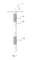
- the presence of the deformable element 12 is designed to allow each rigid element 11 at least one degree of freedom.
- the apparatus of the present invention is of the 2D type, which means that each rigid element 11 has 2 degrees of freedom, and particularly the rigid element 11 may move over a plane x-y relative to an absolute reference frame integral with the earth-gravity reference frame.
- the joint i.e. the deformable connection element 12
- a 3D joint When both measurements of deflection and monitoring of the distance between rigid elements are required, e.g. in case of failures due to soil stabilization or in case of underground collapses, a 3D joint must be used, which allows measurement of the z axis in addition to the x and y axes.
- Figure 1 also shows the removable anchoring and/or locking means 13 as described in the above mentioned document, which allow adhesion of the monitoring apparatus 1 to the soil and/or the walls of the structure to be monitored.
- each rigid element 11 is a multiparameter element, which means that it has various types of sensors, i.e. chemical sensors, temperature sensors, pressure and piezometric level sensors, electric potential meters ad well as position and tilt sensors.
- sensors i.e. chemical sensors, temperature sensors, pressure and piezometric level sensors, electric potential meters ad well as position and tilt sensors.
- Each sensor communicates with means for collecting output signals therefrom, which may be mounted in the apparatus, held within the rigid elements 11 or in a separate remote station.
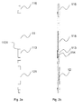
- Figures 2a to 3b show the monitoring apparatus of the present invention according to a preferred embodiment, which solves such drawbacks.
- each of the rigid housing elements 11 contains means 111 for adjusting the operating conditions of the sensors 112 to the operating conditions of the corresponding housing element 11, thereby allowing the output signal of the sensor 112 to be adjusted to a predetermined reference value, which falls within the measurement range of the sensor 112 in the initial installation state of the apparatus.
- each sensor 112 is adjusted by adjusting the initial conditions thereof, the initial conditions being the parameter values as detected by each sensor 112 at the start of detection.
- the monitoring apparatus of the present invention is composed of a plurality of rigid housing elements 11 in the form of tubular cylindrical casings, which tubular cylindrical casing 11 houses a sensor 112 connected to an electronic data collection and processing board 115 which may in turn be connected, through a terminal portion 116 of said casing 11, to a remote unit, not shown.
- the cylindrical casing 11 is connected to a deformable element 12 which consists, in this particular case, of a spring that allows the casing 11 to move with two degrees of freedom.
- the spring 12 may be covered by a reinforced braid 121, which prevents the spring 12 from being crushed at its sides during the movement of the tubular casing 11, and hence restricting such movement of the casing 11.
- FIG. 3a and 3b a detail of the monitoring apparatus of the present invention is shown, in which the sensor is a position sensor and the adjustment means consist of a support element 111 for said sensor 112.
- the support element 111 is mounted in the tubular housing casing 11, to be movable with at least one degree of freedom relative to the reference frame thereof, and control means 1111 are provided for controlling the displacement of the support element 11 to one of a plurality of positions.
- the control means 1111 are also designed to lock the predetermined position and can be accessed from the outside through an access aperture 114 having a removable sealing cover 113.
- control means may be arranged to be actuated externally to and/or remotely from the rigid housing element 11 and preferably to be electronically controlled through the electronic control board 115.
- control means 1112 may be provided for controlling the movement of the support element 111, which are adapted to allow a check of the output signal of the sensor 112 and/or the operating condition that has been set.
- the sensor 112 is a tilt sensor 112 mounted to a swinging plate 111 which acts as a support element therefor and allows the position of the sensor 112 to be changed, and thus change its reference frame.
- the senor 112 initially has a reference frame integral with the one of the tubular casing 11, i.e. with the axes oriented in the same direction. If the reference frame of the casing 11 is not integral with the earth-gravity reference frame, i.e. if the apparatus is positioned with some inclination to the vertical axis, then the swinging plate 111 allows the orientation of the sensor 112 to be rotated for its reference frame to be integral with the absolute earth-gravity reference frame.
- the support plate 111 rotates about the x axis, although it can also rotate about the y and z axes.
- the sensor rotation control means consist of a spherical level 1112 which can check whether the "0" output value of the tilt sensor 112 actually derives from a match of the reference frame of the sensor 112 with the absolute reference frame, and in this particular case whether the z axis of the sensor 112 is coincident with the vertical axis of the absolute reference frame.
- the control means 1111 may be accessed for adjustment of the tilt of the support plate 111 through the aperture 114 formed on the shell wall of the rigid tubular casing 11.
- the aperture 114 also has removable sealing means 113 (as shown in Figure 2a ) consisting of a tubular sleeve 113, which is mounted to slide along the lateral surface of the rigid casing 11, and whose sealing action is ensured by two O-rings 1131 or the like at each of the ends of the sleeve 113.
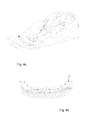
- FIGS 4a to 4d show possible ways of use of the monitoring apparatus of the present invention.
- each tilt sensor 112 may be adjusted according to the positioning arrangement of the casing 11 in which it is held, and in a different manner for each casing, the monitoring apparatus of the present invention may be advantageously used on walls 3 with profiles including many direction and inclination changes, like in Figure 4b or in the tunnel of Figure 4a .
- a further application of the apparatus of the present invention is for sub-horizontal installations in trenches, as shown in Figures 4c and 4d .
- This configuration is particularly advantageous and suitable when monitoring is performed on shallow soil movements or in the analysis of flowslide, debris flows or soil slip initiation conditions.
- the multiparameter monitoring apparatus for monitoring tilt, acceleration, fluid pressure, temperature, etc.
- the multiparameter monitoring apparatus allows direct geotechnical monitoring in the unstable deposit, along the entire section at risk and in a continuous manner, to detect precursors of mechanisms like debris flows, which can be difficultly sensed by instruments unless at shallow depth.
Landscapes
- Engineering & Computer Science (AREA)
- Life Sciences & Earth Sciences (AREA)
- Physics & Mathematics (AREA)
- Mining & Mineral Resources (AREA)
- Chemical & Material Sciences (AREA)
- Geology (AREA)
- General Life Sciences & Earth Sciences (AREA)
- Environmental & Geological Engineering (AREA)
- Analytical Chemistry (AREA)
- Remote Sensing (AREA)
- Health & Medical Sciences (AREA)
- General Physics & Mathematics (AREA)
- Pathology (AREA)
- Multimedia (AREA)
- Food Science & Technology (AREA)
- Biochemistry (AREA)
- General Health & Medical Sciences (AREA)
- Immunology (AREA)
- Radar, Positioning & Navigation (AREA)
- Geophysics (AREA)
- Fluid Mechanics (AREA)
- Medicinal Chemistry (AREA)
- Geochemistry & Mineralogy (AREA)
- Soil Sciences (AREA)
- Paleontology (AREA)
- Civil Engineering (AREA)
- General Engineering & Computer Science (AREA)
- Structural Engineering (AREA)
- Testing Or Calibration Of Command Recording Devices (AREA)
- Geophysics And Detection Of Objects (AREA)
- Devices Affording Protection Of Roads Or Walls For Sound Insulation (AREA)
Applications Claiming Priority (1)
| Application Number | Priority Date | Filing Date | Title |
|---|---|---|---|
| IT000045A ITGE20110045A1 (it) | 2011-04-18 | 2011-04-18 | Dispositivo e metodo per il monitoraggio di parametri geotecnici-strutturali di terreni, rocce e strutture in genere, in fori diversamente inclinati o giaciture su superfici aventi diversi orientamenti spaziali |
Publications (3)
| Publication Number | Publication Date |
|---|---|
| EP2514916A2 true EP2514916A2 (de) | 2012-10-24 |
| EP2514916A3 EP2514916A3 (de) | 2013-02-27 |
| EP2514916B1 EP2514916B1 (de) | 2013-09-18 |
Family
ID=44554603
Family Applications (1)
| Application Number | Title | Priority Date | Filing Date |
|---|---|---|---|
| EP20120164493 Active EP2514916B1 (de) | 2011-04-18 | 2012-04-17 | Gerät und Verfahren um geotechnische und strukturelle Boden-, Gestein- oder Konstruktionsparametern zu kontrollieren, in Löchern mit verschiedenen Neigungen oder auf Flächen mit verschiedenen räumlichen Orientierungen |
Country Status (2)
| Country | Link |
|---|---|
| EP (1) | EP2514916B1 (de) |
| IT (1) | ITGE20110045A1 (de) |
Cited By (5)
| Publication number | Priority date | Publication date | Assignee | Title |
|---|---|---|---|---|
| ITUA20163182A1 (it) * | 2016-05-05 | 2017-11-05 | C S G S R L | Dispositivo per il monitoraggio 2D/3D di parametri geotecnici, geologici-strutturali, idrogeologici e geofisici di terreni, rocce e strutture in genere |
| WO2018224703A1 (es) * | 2017-06-09 | 2018-12-13 | Consejo Superior De Investigaciones Cientificas (Csic) | Sonda multiparamétrica para la monitorización de medios subterráneos |
| CN113756788A (zh) * | 2021-10-18 | 2021-12-07 | 中国地质大学(北京) | 一种机械式随钻井斜测量仪 |
| CN115788398A (zh) * | 2022-10-27 | 2023-03-14 | 西北核技术研究所 | 一种用于柔性传感器支架的对心安装装置及方法 |
| CN117330356A (zh) * | 2023-12-01 | 2024-01-02 | 中铁四局集团有限公司 | 一种隧道土壤采样装置及采样方法 |
Citations (1)
| Publication number | Priority date | Publication date | Assignee | Title |
|---|---|---|---|---|
| EP1664486A2 (de) | 2003-09-09 | 2006-06-07 | C.S.G. S.R.L. | Vorrichtung zur überwachung von geotechnischen und strukturellen parametern von böden, gestein und strukturen allgemein |
Family Cites Families (4)
| Publication number | Priority date | Publication date | Assignee | Title |
|---|---|---|---|---|
| US2851785A (en) * | 1956-11-08 | 1958-09-16 | Jersey Prod Res Co | Inclinometer |
| US4399692A (en) * | 1981-01-13 | 1983-08-23 | Sundstrand Data Control Group | Borehole survey apparatus utilizing accelerometers and probe joint measurements |
| FR2730005B1 (fr) * | 1995-01-27 | 1997-04-18 | Antea | Sonde inclinometrique pour la mesure de l'inclinaison d'un puits de forage |
| US8305230B2 (en) * | 2009-05-22 | 2012-11-06 | Gyrodata, Incorporated | Method and apparatus for initialization of a wellbore survey tool |
-
2011
- 2011-04-18 IT IT000045A patent/ITGE20110045A1/it unknown
-
2012
- 2012-04-17 EP EP20120164493 patent/EP2514916B1/de active Active
Patent Citations (1)
| Publication number | Priority date | Publication date | Assignee | Title |
|---|---|---|---|---|
| EP1664486A2 (de) | 2003-09-09 | 2006-06-07 | C.S.G. S.R.L. | Vorrichtung zur überwachung von geotechnischen und strukturellen parametern von böden, gestein und strukturen allgemein |
Cited By (7)
| Publication number | Priority date | Publication date | Assignee | Title |
|---|---|---|---|---|
| ITUA20163182A1 (it) * | 2016-05-05 | 2017-11-05 | C S G S R L | Dispositivo per il monitoraggio 2D/3D di parametri geotecnici, geologici-strutturali, idrogeologici e geofisici di terreni, rocce e strutture in genere |
| WO2017191564A1 (en) * | 2016-05-05 | 2017-11-09 | C.S.G. S.R.L. | Apparatus for 2d/3d monitoring of geotechnical, geological-structural, hydrogeological and geophysical parameters of soils, rocks and structures in general |
| WO2018224703A1 (es) * | 2017-06-09 | 2018-12-13 | Consejo Superior De Investigaciones Cientificas (Csic) | Sonda multiparamétrica para la monitorización de medios subterráneos |
| CN113756788A (zh) * | 2021-10-18 | 2021-12-07 | 中国地质大学(北京) | 一种机械式随钻井斜测量仪 |
| CN115788398A (zh) * | 2022-10-27 | 2023-03-14 | 西北核技术研究所 | 一种用于柔性传感器支架的对心安装装置及方法 |
| CN117330356A (zh) * | 2023-12-01 | 2024-01-02 | 中铁四局集团有限公司 | 一种隧道土壤采样装置及采样方法 |
| CN117330356B (zh) * | 2023-12-01 | 2024-03-26 | 中铁四局集团有限公司 | 一种隧道土壤采样装置及采样方法 |
Also Published As
| Publication number | Publication date |
|---|---|
| ITGE20110045A1 (it) | 2012-10-19 |
| EP2514916B1 (de) | 2013-09-18 |
| EP2514916A3 (de) | 2013-02-27 |
Similar Documents
| Publication | Publication Date | Title |
|---|---|---|
| EP2514916B1 (de) | Gerät und Verfahren um geotechnische und strukturelle Boden-, Gestein- oder Konstruktionsparametern zu kontrollieren, in Löchern mit verschiedenen Neigungen oder auf Flächen mit verschiedenen räumlichen Orientierungen | |
| CN108350734B (zh) | 钻孔测试装置 | |
| US5657547A (en) | Rate gyro wells survey system including nulling system | |
| US8271199B2 (en) | Binning method for borehole imaging | |
| AU2005226023B2 (en) | Method and system for detecting conditions inside a wellbore | |
| US7681663B2 (en) | Methods and systems for determining angular orientation of a drill string | |
| Savvaidis | Existing landslide monitoring systems and techniques | |
| US8061047B2 (en) | Active positioning of downhole devices using spherical motors | |
| US10690805B2 (en) | Borehold testing device | |
| EP0172599A1 (de) | Vorrichtung und Verfahren zur Vermessung von Bohrlöchern | |
| EP1933171B1 (de) | Magnetometer für MWD Anwendungen | |
| KR101184382B1 (ko) | 지진계측 장치 및 이 장치의 설치방법 | |
| Segalini et al. | Underground landslide displacement monitoring: a new MMES based device | |
| WO2009036420A1 (en) | Methods of long-term gravimetric monitoring of carbon dioxide storage in geological formations | |
| RU2488849C1 (ru) | Скважинный трехкомпонентный цифровой акселерометр | |
| GB2027904A (en) | Determining bore-hole orientation | |
| US6370784B1 (en) | Tiltmeter leveling mechanism | |
| CA2484104C (en) | Method and apparatus for mapping the trajectory in the subsurface of a borehole | |
| Abdoun et al. | Field installation details of a wireless shape-acceleration array system for geotechnical applications | |
| Morris et al. | Case studies of a borehole deployable robot for limestone mine profiling and mapping | |
| RU2263782C2 (ru) | Способ непрерывного контроля за направлением действия отклонителя, измерения зенитных и азимутальных углов скважин и устройство для его осуществления | |
| Bennett et al. | Unstable slope monitoring with a wireless Shape-Acceleration Array system | |
| Balek et al. | SHALLOW MOVEMENTS IN CLAY RICH ROCKS DETECTED DURING SUBNORMAL PRECIPITATION PERIOD | |
| Morino et al. | Monitoring | |
| Ning et al. | Case Study: Geotechnical Instrumentation and Monitoring of Alaskan Way Viaduct Replacement Project |
Legal Events
| Date | Code | Title | Description |
|---|---|---|---|
| PUAI | Public reference made under article 153(3) epc to a published international application that has entered the european phase |
Free format text: ORIGINAL CODE: 0009012 |
|
| AK | Designated contracting states |
Kind code of ref document: A2 Designated state(s): AL AT BE BG CH CY CZ DE DK EE ES FI FR GB GR HR HU IE IS IT LI LT LU LV MC MK MT NL NO PL PT RO RS SE SI SK SM TR |
|
| AX | Request for extension of the european patent |
Extension state: BA ME |
|
| PUAL | Search report despatched |
Free format text: ORIGINAL CODE: 0009013 |
|
| AK | Designated contracting states |
Kind code of ref document: A3 Designated state(s): AL AT BE BG CH CY CZ DE DK EE ES FI FR GB GR HR HU IE IS IT LI LT LU LV MC MK MT NL NO PL PT RO RS SE SI SK SM TR |
|
| AX | Request for extension of the european patent |
Extension state: BA ME |
|
| RIC1 | Information provided on ipc code assigned before grant |
Ipc: E21B 47/022 20120101AFI20130122BHEP Ipc: E02D 1/02 20060101ALI20130122BHEP |
|
| REG | Reference to a national code |
Ref country code: DE Ref legal event code: R079 Ref document number: 602012000304 Country of ref document: DE Free format text: PREVIOUS MAIN CLASS: E21B0047022000 Ipc: E02D0001020000 |
|
| 17P | Request for examination filed |
Effective date: 20130321 |
|
| RIC1 | Information provided on ipc code assigned before grant |
Ipc: E02D 1/02 20060101AFI20130415BHEP Ipc: E21B 47/022 20120101ALI20130415BHEP Ipc: G01N 33/24 20060101ALI20130415BHEP |
|
| GRAP | Despatch of communication of intention to grant a patent |
Free format text: ORIGINAL CODE: EPIDOSNIGR1 |
|
| INTG | Intention to grant announced |
Effective date: 20130527 |
|
| GRAS | Grant fee paid |
Free format text: ORIGINAL CODE: EPIDOSNIGR3 |
|
| GRAA | (expected) grant |
Free format text: ORIGINAL CODE: 0009210 |
|
| AK | Designated contracting states |
Kind code of ref document: B1 Designated state(s): AL AT BE BG CH CY CZ DE DK EE ES FI FR GB GR HR HU IE IS IT LI LT LU LV MC MK MT NL NO PL PT RO RS SE SI SK SM TR |
|
| REG | Reference to a national code |
Ref country code: GB Ref legal event code: FG4D |
|
| REG | Reference to a national code |
Ref country code: CH Ref legal event code: NV Representative=s name: STUMP UND PARTNER PATENTANWAELTE AG, CH Ref country code: CH Ref legal event code: EP |
|
| REG | Reference to a national code |
Ref country code: IE Ref legal event code: FG4D |
|
| REG | Reference to a national code |
Ref country code: AT Ref legal event code: REF Ref document number: 632883 Country of ref document: AT Kind code of ref document: T Effective date: 20131015 |
|
| REG | Reference to a national code |
Ref country code: DE Ref legal event code: R096 Ref document number: 602012000304 Country of ref document: DE Effective date: 20131114 |
|
| REG | Reference to a national code |
Ref country code: CH Ref legal event code: PCAR Free format text: NEW ADDRESS: ZIMMERGASSE 16, 8008 ZUERICH (CH) |
|
| PG25 | Lapsed in a contracting state [announced via postgrant information from national office to epo] |
Ref country code: HR Free format text: LAPSE BECAUSE OF FAILURE TO SUBMIT A TRANSLATION OF THE DESCRIPTION OR TO PAY THE FEE WITHIN THE PRESCRIBED TIME-LIMIT Effective date: 20130918 Ref country code: LT Free format text: LAPSE BECAUSE OF FAILURE TO SUBMIT A TRANSLATION OF THE DESCRIPTION OR TO PAY THE FEE WITHIN THE PRESCRIBED TIME-LIMIT Effective date: 20130918 Ref country code: SE Free format text: LAPSE BECAUSE OF FAILURE TO SUBMIT A TRANSLATION OF THE DESCRIPTION OR TO PAY THE FEE WITHIN THE PRESCRIBED TIME-LIMIT Effective date: 20130918 Ref country code: NO Free format text: LAPSE BECAUSE OF FAILURE TO SUBMIT A TRANSLATION OF THE DESCRIPTION OR TO PAY THE FEE WITHIN THE PRESCRIBED TIME-LIMIT Effective date: 20131218 Ref country code: CY Free format text: LAPSE BECAUSE OF FAILURE TO SUBMIT A TRANSLATION OF THE DESCRIPTION OR TO PAY THE FEE WITHIN THE PRESCRIBED TIME-LIMIT Effective date: 20130918 |
|
| REG | Reference to a national code |
Ref country code: NL Ref legal event code: VDEP Effective date: 20130918 |
|
| REG | Reference to a national code |
Ref country code: AT Ref legal event code: MK05 Ref document number: 632883 Country of ref document: AT Kind code of ref document: T Effective date: 20130918 |
|
| REG | Reference to a national code |
Ref country code: LT Ref legal event code: MG4D |
|
| PG25 | Lapsed in a contracting state [announced via postgrant information from national office to epo] |
Ref country code: SI Free format text: LAPSE BECAUSE OF FAILURE TO SUBMIT A TRANSLATION OF THE DESCRIPTION OR TO PAY THE FEE WITHIN THE PRESCRIBED TIME-LIMIT Effective date: 20130918 Ref country code: GR Free format text: LAPSE BECAUSE OF FAILURE TO SUBMIT A TRANSLATION OF THE DESCRIPTION OR TO PAY THE FEE WITHIN THE PRESCRIBED TIME-LIMIT Effective date: 20131219 Ref country code: LV Free format text: LAPSE BECAUSE OF FAILURE TO SUBMIT A TRANSLATION OF THE DESCRIPTION OR TO PAY THE FEE WITHIN THE PRESCRIBED TIME-LIMIT Effective date: 20130918 Ref country code: FI Free format text: LAPSE BECAUSE OF FAILURE TO SUBMIT A TRANSLATION OF THE DESCRIPTION OR TO PAY THE FEE WITHIN THE PRESCRIBED TIME-LIMIT Effective date: 20130918 Ref country code: RS Free format text: LAPSE BECAUSE OF FAILURE TO SUBMIT A TRANSLATION OF THE DESCRIPTION OR TO PAY THE FEE WITHIN THE PRESCRIBED TIME-LIMIT Effective date: 20130918 |
|
| PG25 | Lapsed in a contracting state [announced via postgrant information from national office to epo] |
Ref country code: BE Free format text: LAPSE BECAUSE OF FAILURE TO SUBMIT A TRANSLATION OF THE DESCRIPTION OR TO PAY THE FEE WITHIN THE PRESCRIBED TIME-LIMIT Effective date: 20130918 |
|
| PG25 | Lapsed in a contracting state [announced via postgrant information from national office to epo] |
Ref country code: SK Free format text: LAPSE BECAUSE OF FAILURE TO SUBMIT A TRANSLATION OF THE DESCRIPTION OR TO PAY THE FEE WITHIN THE PRESCRIBED TIME-LIMIT Effective date: 20130918 Ref country code: IS Free format text: LAPSE BECAUSE OF FAILURE TO SUBMIT A TRANSLATION OF THE DESCRIPTION OR TO PAY THE FEE WITHIN THE PRESCRIBED TIME-LIMIT Effective date: 20140118 Ref country code: CZ Free format text: LAPSE BECAUSE OF FAILURE TO SUBMIT A TRANSLATION OF THE DESCRIPTION OR TO PAY THE FEE WITHIN THE PRESCRIBED TIME-LIMIT Effective date: 20130918 Ref country code: EE Free format text: LAPSE BECAUSE OF FAILURE TO SUBMIT A TRANSLATION OF THE DESCRIPTION OR TO PAY THE FEE WITHIN THE PRESCRIBED TIME-LIMIT Effective date: 20130918 Ref country code: NL Free format text: LAPSE BECAUSE OF FAILURE TO SUBMIT A TRANSLATION OF THE DESCRIPTION OR TO PAY THE FEE WITHIN THE PRESCRIBED TIME-LIMIT Effective date: 20130918 |
|
| PG25 | Lapsed in a contracting state [announced via postgrant information from national office to epo] |
Ref country code: AT Free format text: LAPSE BECAUSE OF FAILURE TO SUBMIT A TRANSLATION OF THE DESCRIPTION OR TO PAY THE FEE WITHIN THE PRESCRIBED TIME-LIMIT Effective date: 20130918 Ref country code: ES Free format text: LAPSE BECAUSE OF FAILURE TO SUBMIT A TRANSLATION OF THE DESCRIPTION OR TO PAY THE FEE WITHIN THE PRESCRIBED TIME-LIMIT Effective date: 20130918 Ref country code: PL Free format text: LAPSE BECAUSE OF FAILURE TO SUBMIT A TRANSLATION OF THE DESCRIPTION OR TO PAY THE FEE WITHIN THE PRESCRIBED TIME-LIMIT Effective date: 20130918 |
|
| REG | Reference to a national code |
Ref country code: DE Ref legal event code: R097 Ref document number: 602012000304 Country of ref document: DE |
|
| PG25 | Lapsed in a contracting state [announced via postgrant information from national office to epo] |
Ref country code: PT Free format text: LAPSE BECAUSE OF FAILURE TO SUBMIT A TRANSLATION OF THE DESCRIPTION OR TO PAY THE FEE WITHIN THE PRESCRIBED TIME-LIMIT Effective date: 20140120 |
|
| PLBE | No opposition filed within time limit |
Free format text: ORIGINAL CODE: 0009261 |
|
| STAA | Information on the status of an ep patent application or granted ep patent |
Free format text: STATUS: NO OPPOSITION FILED WITHIN TIME LIMIT |
|
| 26N | No opposition filed |
Effective date: 20140619 |
|
| PG25 | Lapsed in a contracting state [announced via postgrant information from national office to epo] |
Ref country code: DK Free format text: LAPSE BECAUSE OF FAILURE TO SUBMIT A TRANSLATION OF THE DESCRIPTION OR TO PAY THE FEE WITHIN THE PRESCRIBED TIME-LIMIT Effective date: 20130918 |
|
| REG | Reference to a national code |
Ref country code: DE Ref legal event code: R097 Ref document number: 602012000304 Country of ref document: DE Effective date: 20140619 |
|
| PG25 | Lapsed in a contracting state [announced via postgrant information from national office to epo] |
Ref country code: LU Free format text: LAPSE BECAUSE OF FAILURE TO SUBMIT A TRANSLATION OF THE DESCRIPTION OR TO PAY THE FEE WITHIN THE PRESCRIBED TIME-LIMIT Effective date: 20140417 Ref country code: MC Free format text: LAPSE BECAUSE OF FAILURE TO SUBMIT A TRANSLATION OF THE DESCRIPTION OR TO PAY THE FEE WITHIN THE PRESCRIBED TIME-LIMIT Effective date: 20130918 |
|
| REG | Reference to a national code |
Ref country code: IE Ref legal event code: MM4A |
|
| PG25 | Lapsed in a contracting state [announced via postgrant information from national office to epo] |
Ref country code: IE Free format text: LAPSE BECAUSE OF NON-PAYMENT OF DUE FEES Effective date: 20140417 |
|
| PG25 | Lapsed in a contracting state [announced via postgrant information from national office to epo] |
Ref country code: MT Free format text: LAPSE BECAUSE OF FAILURE TO SUBMIT A TRANSLATION OF THE DESCRIPTION OR TO PAY THE FEE WITHIN THE PRESCRIBED TIME-LIMIT Effective date: 20130918 |
|
| REG | Reference to a national code |
Ref country code: FR Ref legal event code: PLFP Year of fee payment: 5 |
|
| PG25 | Lapsed in a contracting state [announced via postgrant information from national office to epo] |
Ref country code: SM Free format text: LAPSE BECAUSE OF FAILURE TO SUBMIT A TRANSLATION OF THE DESCRIPTION OR TO PAY THE FEE WITHIN THE PRESCRIBED TIME-LIMIT Effective date: 20130918 |
|
| PG25 | Lapsed in a contracting state [announced via postgrant information from national office to epo] |
Ref country code: RO Free format text: LAPSE BECAUSE OF FAILURE TO SUBMIT A TRANSLATION OF THE DESCRIPTION OR TO PAY THE FEE WITHIN THE PRESCRIBED TIME-LIMIT Effective date: 20130918 |
|
| PG25 | Lapsed in a contracting state [announced via postgrant information from national office to epo] |
Ref country code: BG Free format text: LAPSE BECAUSE OF FAILURE TO SUBMIT A TRANSLATION OF THE DESCRIPTION OR TO PAY THE FEE WITHIN THE PRESCRIBED TIME-LIMIT Effective date: 20130918 |
|
| PG25 | Lapsed in a contracting state [announced via postgrant information from national office to epo] |
Ref country code: HU Free format text: LAPSE BECAUSE OF FAILURE TO SUBMIT A TRANSLATION OF THE DESCRIPTION OR TO PAY THE FEE WITHIN THE PRESCRIBED TIME-LIMIT; INVALID AB INITIO Effective date: 20120417 Ref country code: TR Free format text: LAPSE BECAUSE OF FAILURE TO SUBMIT A TRANSLATION OF THE DESCRIPTION OR TO PAY THE FEE WITHIN THE PRESCRIBED TIME-LIMIT Effective date: 20130918 |
|
| REG | Reference to a national code |
Ref country code: FR Ref legal event code: PLFP Year of fee payment: 6 |
|
| REG | Reference to a national code |
Ref country code: FR Ref legal event code: PLFP Year of fee payment: 7 |
|
| PG25 | Lapsed in a contracting state [announced via postgrant information from national office to epo] |
Ref country code: MK Free format text: LAPSE BECAUSE OF FAILURE TO SUBMIT A TRANSLATION OF THE DESCRIPTION OR TO PAY THE FEE WITHIN THE PRESCRIBED TIME-LIMIT Effective date: 20130918 |
|
| PGFP | Annual fee paid to national office [announced via postgrant information from national office to epo] |
Ref country code: DE Payment date: 20180424 Year of fee payment: 7 |
|
| PGFP | Annual fee paid to national office [announced via postgrant information from national office to epo] |
Ref country code: FR Payment date: 20180427 Year of fee payment: 7 |
|
| PG25 | Lapsed in a contracting state [announced via postgrant information from national office to epo] |
Ref country code: AL Free format text: LAPSE BECAUSE OF FAILURE TO SUBMIT A TRANSLATION OF THE DESCRIPTION OR TO PAY THE FEE WITHIN THE PRESCRIBED TIME-LIMIT Effective date: 20130918 |
|
| PGFP | Annual fee paid to national office [announced via postgrant information from national office to epo] |
Ref country code: GB Payment date: 20190424 Year of fee payment: 8 |
|
| REG | Reference to a national code |
Ref country code: DE Ref legal event code: R119 Ref document number: 602012000304 Country of ref document: DE |
|
| PG25 | Lapsed in a contracting state [announced via postgrant information from national office to epo] |
Ref country code: DE Free format text: LAPSE BECAUSE OF NON-PAYMENT OF DUE FEES Effective date: 20191101 |
|
| PG25 | Lapsed in a contracting state [announced via postgrant information from national office to epo] |
Ref country code: FR Free format text: LAPSE BECAUSE OF NON-PAYMENT OF DUE FEES Effective date: 20190430 |
|
| GBPC | Gb: european patent ceased through non-payment of renewal fee |
Effective date: 20200417 |
|
| PG25 | Lapsed in a contracting state [announced via postgrant information from national office to epo] |
Ref country code: GB Free format text: LAPSE BECAUSE OF NON-PAYMENT OF DUE FEES Effective date: 20200417 |
|
| PGFP | Annual fee paid to national office [announced via postgrant information from national office to epo] |
Ref country code: IT Payment date: 20230404 Year of fee payment: 12 Ref country code: CH Payment date: 20230502 Year of fee payment: 12 |