EP2514850A1 - Method for producing a heat-shielding coating, turbine member provided with said heat-shielding coating, and gas turbine - Google Patents
Method for producing a heat-shielding coating, turbine member provided with said heat-shielding coating, and gas turbine Download PDFInfo
- Publication number
- EP2514850A1 EP2514850A1 EP10837321A EP10837321A EP2514850A1 EP 2514850 A1 EP2514850 A1 EP 2514850A1 EP 10837321 A EP10837321 A EP 10837321A EP 10837321 A EP10837321 A EP 10837321A EP 2514850 A1 EP2514850 A1 EP 2514850A1
- Authority
- EP
- European Patent Office
- Prior art keywords
- thermal
- particle size
- particles
- ceramic layer
- thermal barrier
- Prior art date
- Legal status (The legal status is an assumption and is not a legal conclusion. Google has not performed a legal analysis and makes no representation as to the accuracy of the status listed.)
- Granted
Links
Images


Classifications
-
- C—CHEMISTRY; METALLURGY
- C23—COATING METALLIC MATERIAL; COATING MATERIAL WITH METALLIC MATERIAL; CHEMICAL SURFACE TREATMENT; DIFFUSION TREATMENT OF METALLIC MATERIAL; COATING BY VACUUM EVAPORATION, BY SPUTTERING, BY ION IMPLANTATION OR BY CHEMICAL VAPOUR DEPOSITION, IN GENERAL; INHIBITING CORROSION OF METALLIC MATERIAL OR INCRUSTATION IN GENERAL
- C23C—COATING METALLIC MATERIAL; COATING MATERIAL WITH METALLIC MATERIAL; SURFACE TREATMENT OF METALLIC MATERIAL BY DIFFUSION INTO THE SURFACE, BY CHEMICAL CONVERSION OR SUBSTITUTION; COATING BY VACUUM EVAPORATION, BY SPUTTERING, BY ION IMPLANTATION OR BY CHEMICAL VAPOUR DEPOSITION, IN GENERAL
- C23C4/00—Coating by spraying the coating material in the molten state, e.g. by flame, plasma or electric discharge
- C23C4/04—Coating by spraying the coating material in the molten state, e.g. by flame, plasma or electric discharge characterised by the coating material
-
- C—CHEMISTRY; METALLURGY
- C04—CEMENTS; CONCRETE; ARTIFICIAL STONE; CERAMICS; REFRACTORIES
- C04B—LIME, MAGNESIA; SLAG; CEMENTS; COMPOSITIONS THEREOF, e.g. MORTARS, CONCRETE OR LIKE BUILDING MATERIALS; ARTIFICIAL STONE; CERAMICS; REFRACTORIES; TREATMENT OF NATURAL STONE
- C04B41/00—After-treatment of mortars, concrete, artificial stone or ceramics; Treatment of natural stone
- C04B41/45—Coating or impregnating, e.g. injection in masonry, partial coating of green or fired ceramics, organic coating compositions for adhering together two concrete elements
-
- C—CHEMISTRY; METALLURGY
- C04—CEMENTS; CONCRETE; ARTIFICIAL STONE; CERAMICS; REFRACTORIES
- C04B—LIME, MAGNESIA; SLAG; CEMENTS; COMPOSITIONS THEREOF, e.g. MORTARS, CONCRETE OR LIKE BUILDING MATERIALS; ARTIFICIAL STONE; CERAMICS; REFRACTORIES; TREATMENT OF NATURAL STONE
- C04B41/00—After-treatment of mortars, concrete, artificial stone or ceramics; Treatment of natural stone
- C04B41/45—Coating or impregnating, e.g. injection in masonry, partial coating of green or fired ceramics, organic coating compositions for adhering together two concrete elements
- C04B41/4505—Coating or impregnating, e.g. injection in masonry, partial coating of green or fired ceramics, organic coating compositions for adhering together two concrete elements characterised by the method of application
- C04B41/4523—Coating or impregnating, e.g. injection in masonry, partial coating of green or fired ceramics, organic coating compositions for adhering together two concrete elements characterised by the method of application applied from the molten state ; Thermal spraying, e.g. plasma spraying
-
- C—CHEMISTRY; METALLURGY
- C23—COATING METALLIC MATERIAL; COATING MATERIAL WITH METALLIC MATERIAL; CHEMICAL SURFACE TREATMENT; DIFFUSION TREATMENT OF METALLIC MATERIAL; COATING BY VACUUM EVAPORATION, BY SPUTTERING, BY ION IMPLANTATION OR BY CHEMICAL VAPOUR DEPOSITION, IN GENERAL; INHIBITING CORROSION OF METALLIC MATERIAL OR INCRUSTATION IN GENERAL
- C23C—COATING METALLIC MATERIAL; COATING MATERIAL WITH METALLIC MATERIAL; SURFACE TREATMENT OF METALLIC MATERIAL BY DIFFUSION INTO THE SURFACE, BY CHEMICAL CONVERSION OR SUBSTITUTION; COATING BY VACUUM EVAPORATION, BY SPUTTERING, BY ION IMPLANTATION OR BY CHEMICAL VAPOUR DEPOSITION, IN GENERAL
- C23C28/00—Coating for obtaining at least two superposed coatings either by methods not provided for in a single one of groups C23C2/00 - C23C26/00 or by combinations of methods provided for in subclasses C23C and C25C or C25D
- C23C28/30—Coatings combining at least one metallic layer and at least one inorganic non-metallic layer
-
- C—CHEMISTRY; METALLURGY
- C23—COATING METALLIC MATERIAL; COATING MATERIAL WITH METALLIC MATERIAL; CHEMICAL SURFACE TREATMENT; DIFFUSION TREATMENT OF METALLIC MATERIAL; COATING BY VACUUM EVAPORATION, BY SPUTTERING, BY ION IMPLANTATION OR BY CHEMICAL VAPOUR DEPOSITION, IN GENERAL; INHIBITING CORROSION OF METALLIC MATERIAL OR INCRUSTATION IN GENERAL
- C23C—COATING METALLIC MATERIAL; COATING MATERIAL WITH METALLIC MATERIAL; SURFACE TREATMENT OF METALLIC MATERIAL BY DIFFUSION INTO THE SURFACE, BY CHEMICAL CONVERSION OR SUBSTITUTION; COATING BY VACUUM EVAPORATION, BY SPUTTERING, BY ION IMPLANTATION OR BY CHEMICAL VAPOUR DEPOSITION, IN GENERAL
- C23C28/00—Coating for obtaining at least two superposed coatings either by methods not provided for in a single one of groups C23C2/00 - C23C26/00 or by combinations of methods provided for in subclasses C23C and C25C or C25D
- C23C28/30—Coatings combining at least one metallic layer and at least one inorganic non-metallic layer
- C23C28/32—Coatings combining at least one metallic layer and at least one inorganic non-metallic layer including at least one pure metallic layer
- C23C28/321—Coatings combining at least one metallic layer and at least one inorganic non-metallic layer including at least one pure metallic layer with at least one metal alloy layer
- C23C28/3215—Coatings combining at least one metallic layer and at least one inorganic non-metallic layer including at least one pure metallic layer with at least one metal alloy layer at least one MCrAlX layer
-
- C—CHEMISTRY; METALLURGY
- C23—COATING METALLIC MATERIAL; COATING MATERIAL WITH METALLIC MATERIAL; CHEMICAL SURFACE TREATMENT; DIFFUSION TREATMENT OF METALLIC MATERIAL; COATING BY VACUUM EVAPORATION, BY SPUTTERING, BY ION IMPLANTATION OR BY CHEMICAL VAPOUR DEPOSITION, IN GENERAL; INHIBITING CORROSION OF METALLIC MATERIAL OR INCRUSTATION IN GENERAL
- C23C—COATING METALLIC MATERIAL; COATING MATERIAL WITH METALLIC MATERIAL; SURFACE TREATMENT OF METALLIC MATERIAL BY DIFFUSION INTO THE SURFACE, BY CHEMICAL CONVERSION OR SUBSTITUTION; COATING BY VACUUM EVAPORATION, BY SPUTTERING, BY ION IMPLANTATION OR BY CHEMICAL VAPOUR DEPOSITION, IN GENERAL
- C23C28/00—Coating for obtaining at least two superposed coatings either by methods not provided for in a single one of groups C23C2/00 - C23C26/00 or by combinations of methods provided for in subclasses C23C and C25C or C25D
- C23C28/30—Coatings combining at least one metallic layer and at least one inorganic non-metallic layer
- C23C28/34—Coatings combining at least one metallic layer and at least one inorganic non-metallic layer including at least one inorganic non-metallic material layer, e.g. metal carbide, nitride, boride, silicide layer and their mixtures, enamels, phosphates and sulphates
- C23C28/345—Coatings combining at least one metallic layer and at least one inorganic non-metallic layer including at least one inorganic non-metallic material layer, e.g. metal carbide, nitride, boride, silicide layer and their mixtures, enamels, phosphates and sulphates with at least one oxide layer
-
- C—CHEMISTRY; METALLURGY
- C23—COATING METALLIC MATERIAL; COATING MATERIAL WITH METALLIC MATERIAL; CHEMICAL SURFACE TREATMENT; DIFFUSION TREATMENT OF METALLIC MATERIAL; COATING BY VACUUM EVAPORATION, BY SPUTTERING, BY ION IMPLANTATION OR BY CHEMICAL VAPOUR DEPOSITION, IN GENERAL; INHIBITING CORROSION OF METALLIC MATERIAL OR INCRUSTATION IN GENERAL
- C23C—COATING METALLIC MATERIAL; COATING MATERIAL WITH METALLIC MATERIAL; SURFACE TREATMENT OF METALLIC MATERIAL BY DIFFUSION INTO THE SURFACE, BY CHEMICAL CONVERSION OR SUBSTITUTION; COATING BY VACUUM EVAPORATION, BY SPUTTERING, BY ION IMPLANTATION OR BY CHEMICAL VAPOUR DEPOSITION, IN GENERAL
- C23C28/00—Coating for obtaining at least two superposed coatings either by methods not provided for in a single one of groups C23C2/00 - C23C26/00 or by combinations of methods provided for in subclasses C23C and C25C or C25D
- C23C28/30—Coatings combining at least one metallic layer and at least one inorganic non-metallic layer
- C23C28/34—Coatings combining at least one metallic layer and at least one inorganic non-metallic layer including at least one inorganic non-metallic material layer, e.g. metal carbide, nitride, boride, silicide layer and their mixtures, enamels, phosphates and sulphates
- C23C28/345—Coatings combining at least one metallic layer and at least one inorganic non-metallic layer including at least one inorganic non-metallic material layer, e.g. metal carbide, nitride, boride, silicide layer and their mixtures, enamels, phosphates and sulphates with at least one oxide layer
- C23C28/3455—Coatings combining at least one metallic layer and at least one inorganic non-metallic layer including at least one inorganic non-metallic material layer, e.g. metal carbide, nitride, boride, silicide layer and their mixtures, enamels, phosphates and sulphates with at least one oxide layer with a refractory ceramic layer, e.g. refractory metal oxide, ZrO2, rare earth oxides or a thermal barrier system comprising at least one refractory oxide layer
-
- C—CHEMISTRY; METALLURGY
- C23—COATING METALLIC MATERIAL; COATING MATERIAL WITH METALLIC MATERIAL; CHEMICAL SURFACE TREATMENT; DIFFUSION TREATMENT OF METALLIC MATERIAL; COATING BY VACUUM EVAPORATION, BY SPUTTERING, BY ION IMPLANTATION OR BY CHEMICAL VAPOUR DEPOSITION, IN GENERAL; INHIBITING CORROSION OF METALLIC MATERIAL OR INCRUSTATION IN GENERAL
- C23C—COATING METALLIC MATERIAL; COATING MATERIAL WITH METALLIC MATERIAL; SURFACE TREATMENT OF METALLIC MATERIAL BY DIFFUSION INTO THE SURFACE, BY CHEMICAL CONVERSION OR SUBSTITUTION; COATING BY VACUUM EVAPORATION, BY SPUTTERING, BY ION IMPLANTATION OR BY CHEMICAL VAPOUR DEPOSITION, IN GENERAL
- C23C4/00—Coating by spraying the coating material in the molten state, e.g. by flame, plasma or electric discharge
- C23C4/02—Pretreatment of the material to be coated, e.g. for coating on selected surface areas
-
- C—CHEMISTRY; METALLURGY
- C23—COATING METALLIC MATERIAL; COATING MATERIAL WITH METALLIC MATERIAL; CHEMICAL SURFACE TREATMENT; DIFFUSION TREATMENT OF METALLIC MATERIAL; COATING BY VACUUM EVAPORATION, BY SPUTTERING, BY ION IMPLANTATION OR BY CHEMICAL VAPOUR DEPOSITION, IN GENERAL; INHIBITING CORROSION OF METALLIC MATERIAL OR INCRUSTATION IN GENERAL
- C23C—COATING METALLIC MATERIAL; COATING MATERIAL WITH METALLIC MATERIAL; SURFACE TREATMENT OF METALLIC MATERIAL BY DIFFUSION INTO THE SURFACE, BY CHEMICAL CONVERSION OR SUBSTITUTION; COATING BY VACUUM EVAPORATION, BY SPUTTERING, BY ION IMPLANTATION OR BY CHEMICAL VAPOUR DEPOSITION, IN GENERAL
- C23C4/00—Coating by spraying the coating material in the molten state, e.g. by flame, plasma or electric discharge
- C23C4/04—Coating by spraying the coating material in the molten state, e.g. by flame, plasma or electric discharge characterised by the coating material
- C23C4/06—Metallic material
-
- C—CHEMISTRY; METALLURGY
- C23—COATING METALLIC MATERIAL; COATING MATERIAL WITH METALLIC MATERIAL; CHEMICAL SURFACE TREATMENT; DIFFUSION TREATMENT OF METALLIC MATERIAL; COATING BY VACUUM EVAPORATION, BY SPUTTERING, BY ION IMPLANTATION OR BY CHEMICAL VAPOUR DEPOSITION, IN GENERAL; INHIBITING CORROSION OF METALLIC MATERIAL OR INCRUSTATION IN GENERAL
- C23C—COATING METALLIC MATERIAL; COATING MATERIAL WITH METALLIC MATERIAL; SURFACE TREATMENT OF METALLIC MATERIAL BY DIFFUSION INTO THE SURFACE, BY CHEMICAL CONVERSION OR SUBSTITUTION; COATING BY VACUUM EVAPORATION, BY SPUTTERING, BY ION IMPLANTATION OR BY CHEMICAL VAPOUR DEPOSITION, IN GENERAL
- C23C4/00—Coating by spraying the coating material in the molten state, e.g. by flame, plasma or electric discharge
- C23C4/04—Coating by spraying the coating material in the molten state, e.g. by flame, plasma or electric discharge characterised by the coating material
- C23C4/10—Oxides, borides, carbides, nitrides or silicides; Mixtures thereof
-
- C—CHEMISTRY; METALLURGY
- C23—COATING METALLIC MATERIAL; COATING MATERIAL WITH METALLIC MATERIAL; CHEMICAL SURFACE TREATMENT; DIFFUSION TREATMENT OF METALLIC MATERIAL; COATING BY VACUUM EVAPORATION, BY SPUTTERING, BY ION IMPLANTATION OR BY CHEMICAL VAPOUR DEPOSITION, IN GENERAL; INHIBITING CORROSION OF METALLIC MATERIAL OR INCRUSTATION IN GENERAL
- C23C—COATING METALLIC MATERIAL; COATING MATERIAL WITH METALLIC MATERIAL; SURFACE TREATMENT OF METALLIC MATERIAL BY DIFFUSION INTO THE SURFACE, BY CHEMICAL CONVERSION OR SUBSTITUTION; COATING BY VACUUM EVAPORATION, BY SPUTTERING, BY ION IMPLANTATION OR BY CHEMICAL VAPOUR DEPOSITION, IN GENERAL
- C23C4/00—Coating by spraying the coating material in the molten state, e.g. by flame, plasma or electric discharge
- C23C4/04—Coating by spraying the coating material in the molten state, e.g. by flame, plasma or electric discharge characterised by the coating material
- C23C4/10—Oxides, borides, carbides, nitrides or silicides; Mixtures thereof
- C23C4/11—Oxides
-
- C—CHEMISTRY; METALLURGY
- C23—COATING METALLIC MATERIAL; COATING MATERIAL WITH METALLIC MATERIAL; CHEMICAL SURFACE TREATMENT; DIFFUSION TREATMENT OF METALLIC MATERIAL; COATING BY VACUUM EVAPORATION, BY SPUTTERING, BY ION IMPLANTATION OR BY CHEMICAL VAPOUR DEPOSITION, IN GENERAL; INHIBITING CORROSION OF METALLIC MATERIAL OR INCRUSTATION IN GENERAL
- C23C—COATING METALLIC MATERIAL; COATING MATERIAL WITH METALLIC MATERIAL; SURFACE TREATMENT OF METALLIC MATERIAL BY DIFFUSION INTO THE SURFACE, BY CHEMICAL CONVERSION OR SUBSTITUTION; COATING BY VACUUM EVAPORATION, BY SPUTTERING, BY ION IMPLANTATION OR BY CHEMICAL VAPOUR DEPOSITION, IN GENERAL
- C23C4/00—Coating by spraying the coating material in the molten state, e.g. by flame, plasma or electric discharge
- C23C4/12—Coating by spraying the coating material in the molten state, e.g. by flame, plasma or electric discharge characterised by the method of spraying
-
- C—CHEMISTRY; METALLURGY
- C23—COATING METALLIC MATERIAL; COATING MATERIAL WITH METALLIC MATERIAL; CHEMICAL SURFACE TREATMENT; DIFFUSION TREATMENT OF METALLIC MATERIAL; COATING BY VACUUM EVAPORATION, BY SPUTTERING, BY ION IMPLANTATION OR BY CHEMICAL VAPOUR DEPOSITION, IN GENERAL; INHIBITING CORROSION OF METALLIC MATERIAL OR INCRUSTATION IN GENERAL
- C23C—COATING METALLIC MATERIAL; COATING MATERIAL WITH METALLIC MATERIAL; SURFACE TREATMENT OF METALLIC MATERIAL BY DIFFUSION INTO THE SURFACE, BY CHEMICAL CONVERSION OR SUBSTITUTION; COATING BY VACUUM EVAPORATION, BY SPUTTERING, BY ION IMPLANTATION OR BY CHEMICAL VAPOUR DEPOSITION, IN GENERAL
- C23C4/00—Coating by spraying the coating material in the molten state, e.g. by flame, plasma or electric discharge
- C23C4/12—Coating by spraying the coating material in the molten state, e.g. by flame, plasma or electric discharge characterised by the method of spraying
- C23C4/134—Plasma spraying
-
- F—MECHANICAL ENGINEERING; LIGHTING; HEATING; WEAPONS; BLASTING
- F01—MACHINES OR ENGINES IN GENERAL; ENGINE PLANTS IN GENERAL; STEAM ENGINES
- F01D—NON-POSITIVE DISPLACEMENT MACHINES OR ENGINES, e.g. STEAM TURBINES
- F01D5/00—Blades; Blade-carrying members; Heating, heat-insulating, cooling or antivibration means on the blades or the members
- F01D5/12—Blades
- F01D5/28—Selecting particular materials; Particular measures relating thereto; Measures against erosion or corrosion
-
- F—MECHANICAL ENGINEERING; LIGHTING; HEATING; WEAPONS; BLASTING
- F01—MACHINES OR ENGINES IN GENERAL; ENGINE PLANTS IN GENERAL; STEAM ENGINES
- F01D—NON-POSITIVE DISPLACEMENT MACHINES OR ENGINES, e.g. STEAM TURBINES
- F01D5/00—Blades; Blade-carrying members; Heating, heat-insulating, cooling or antivibration means on the blades or the members
- F01D5/12—Blades
- F01D5/28—Selecting particular materials; Particular measures relating thereto; Measures against erosion or corrosion
- F01D5/284—Selection of ceramic materials
-
- F—MECHANICAL ENGINEERING; LIGHTING; HEATING; WEAPONS; BLASTING
- F01—MACHINES OR ENGINES IN GENERAL; ENGINE PLANTS IN GENERAL; STEAM ENGINES
- F01D—NON-POSITIVE DISPLACEMENT MACHINES OR ENGINES, e.g. STEAM TURBINES
- F01D5/00—Blades; Blade-carrying members; Heating, heat-insulating, cooling or antivibration means on the blades or the members
- F01D5/12—Blades
- F01D5/28—Selecting particular materials; Particular measures relating thereto; Measures against erosion or corrosion
- F01D5/286—Particular treatment of blades, e.g. to increase durability or resistance against corrosion or erosion
-
- F—MECHANICAL ENGINEERING; LIGHTING; HEATING; WEAPONS; BLASTING
- F01—MACHINES OR ENGINES IN GENERAL; ENGINE PLANTS IN GENERAL; STEAM ENGINES
- F01D—NON-POSITIVE DISPLACEMENT MACHINES OR ENGINES, e.g. STEAM TURBINES
- F01D5/00—Blades; Blade-carrying members; Heating, heat-insulating, cooling or antivibration means on the blades or the members
- F01D5/12—Blades
- F01D5/28—Selecting particular materials; Particular measures relating thereto; Measures against erosion or corrosion
- F01D5/288—Protective coatings for blades
-
- Y—GENERAL TAGGING OF NEW TECHNOLOGICAL DEVELOPMENTS; GENERAL TAGGING OF CROSS-SECTIONAL TECHNOLOGIES SPANNING OVER SEVERAL SECTIONS OF THE IPC; TECHNICAL SUBJECTS COVERED BY FORMER USPC CROSS-REFERENCE ART COLLECTIONS [XRACs] AND DIGESTS
- Y10—TECHNICAL SUBJECTS COVERED BY FORMER USPC
- Y10T—TECHNICAL SUBJECTS COVERED BY FORMER US CLASSIFICATION
- Y10T428/00—Stock material or miscellaneous articles
- Y10T428/12—All metal or with adjacent metals
- Y10T428/12493—Composite; i.e., plural, adjacent, spatially distinct metal components [e.g., layers, joint, etc.]
- Y10T428/12535—Composite; i.e., plural, adjacent, spatially distinct metal components [e.g., layers, joint, etc.] with additional, spatially distinct nonmetal component
- Y10T428/12611—Oxide-containing component
-
- Y—GENERAL TAGGING OF NEW TECHNOLOGICAL DEVELOPMENTS; GENERAL TAGGING OF CROSS-SECTIONAL TECHNOLOGIES SPANNING OVER SEVERAL SECTIONS OF THE IPC; TECHNICAL SUBJECTS COVERED BY FORMER USPC CROSS-REFERENCE ART COLLECTIONS [XRACs] AND DIGESTS
- Y10—TECHNICAL SUBJECTS COVERED BY FORMER USPC
- Y10T—TECHNICAL SUBJECTS COVERED BY FORMER US CLASSIFICATION
- Y10T428/00—Stock material or miscellaneous articles
- Y10T428/12—All metal or with adjacent metals
- Y10T428/12493—Composite; i.e., plural, adjacent, spatially distinct metal components [e.g., layers, joint, etc.]
- Y10T428/12535—Composite; i.e., plural, adjacent, spatially distinct metal components [e.g., layers, joint, etc.] with additional, spatially distinct nonmetal component
- Y10T428/12611—Oxide-containing component
- Y10T428/12618—Plural oxides
-
- Y—GENERAL TAGGING OF NEW TECHNOLOGICAL DEVELOPMENTS; GENERAL TAGGING OF CROSS-SECTIONAL TECHNOLOGIES SPANNING OVER SEVERAL SECTIONS OF THE IPC; TECHNICAL SUBJECTS COVERED BY FORMER USPC CROSS-REFERENCE ART COLLECTIONS [XRACs] AND DIGESTS
- Y10—TECHNICAL SUBJECTS COVERED BY FORMER USPC
- Y10T—TECHNICAL SUBJECTS COVERED BY FORMER US CLASSIFICATION
- Y10T428/00—Stock material or miscellaneous articles
- Y10T428/12—All metal or with adjacent metals
- Y10T428/12493—Composite; i.e., plural, adjacent, spatially distinct metal components [e.g., layers, joint, etc.]
- Y10T428/12771—Transition metal-base component
- Y10T428/12861—Group VIII or IB metal-base component
- Y10T428/12931—Co-, Fe-, or Ni-base components, alternative to each other
-
- Y—GENERAL TAGGING OF NEW TECHNOLOGICAL DEVELOPMENTS; GENERAL TAGGING OF CROSS-SECTIONAL TECHNOLOGIES SPANNING OVER SEVERAL SECTIONS OF THE IPC; TECHNICAL SUBJECTS COVERED BY FORMER USPC CROSS-REFERENCE ART COLLECTIONS [XRACs] AND DIGESTS
- Y10—TECHNICAL SUBJECTS COVERED BY FORMER USPC
- Y10T—TECHNICAL SUBJECTS COVERED BY FORMER US CLASSIFICATION
- Y10T428/00—Stock material or miscellaneous articles
- Y10T428/12—All metal or with adjacent metals
- Y10T428/12493—Composite; i.e., plural, adjacent, spatially distinct metal components [e.g., layers, joint, etc.]
- Y10T428/12771—Transition metal-base component
- Y10T428/12861—Group VIII or IB metal-base component
- Y10T428/12937—Co- or Ni-base component next to Fe-base component
-
- Y—GENERAL TAGGING OF NEW TECHNOLOGICAL DEVELOPMENTS; GENERAL TAGGING OF CROSS-SECTIONAL TECHNOLOGIES SPANNING OVER SEVERAL SECTIONS OF THE IPC; TECHNICAL SUBJECTS COVERED BY FORMER USPC CROSS-REFERENCE ART COLLECTIONS [XRACs] AND DIGESTS
- Y10—TECHNICAL SUBJECTS COVERED BY FORMER USPC
- Y10T—TECHNICAL SUBJECTS COVERED BY FORMER US CLASSIFICATION
- Y10T428/00—Stock material or miscellaneous articles
- Y10T428/12—All metal or with adjacent metals
- Y10T428/12493—Composite; i.e., plural, adjacent, spatially distinct metal components [e.g., layers, joint, etc.]
- Y10T428/12771—Transition metal-base component
- Y10T428/12861—Group VIII or IB metal-base component
- Y10T428/12944—Ni-base component
-
- Y—GENERAL TAGGING OF NEW TECHNOLOGICAL DEVELOPMENTS; GENERAL TAGGING OF CROSS-SECTIONAL TECHNOLOGIES SPANNING OVER SEVERAL SECTIONS OF THE IPC; TECHNICAL SUBJECTS COVERED BY FORMER USPC CROSS-REFERENCE ART COLLECTIONS [XRACs] AND DIGESTS
- Y10—TECHNICAL SUBJECTS COVERED BY FORMER USPC
- Y10T—TECHNICAL SUBJECTS COVERED BY FORMER US CLASSIFICATION
- Y10T428/00—Stock material or miscellaneous articles
- Y10T428/12—All metal or with adjacent metals
- Y10T428/12493—Composite; i.e., plural, adjacent, spatially distinct metal components [e.g., layers, joint, etc.]
- Y10T428/12771—Transition metal-base component
- Y10T428/12861—Group VIII or IB metal-base component
- Y10T428/12951—Fe-base component
- Y10T428/12972—Containing 0.01-1.7% carbon [i.e., steel]
- Y10T428/12979—Containing more than 10% nonferrous elements [e.g., high alloy, stainless]
Definitions
- a thermal barrier coating is formed by using a deposition process such as thermal spraying to laminate a ceramic layer composed of an oxide ceramic onto the heat-resistant metal substrate, with a metal bonding layer disposed therebetween, thereby protecting the heat-resistant metal substrate from high temperatures.
- ZrO 2 -based materials are used for the ceramic layer, and yttria-stabilized zirconia (YSZ), which is ZrO 2 that has been partially or totally stabilized by Y 2 O 3 , is often used because of its comparatively low thermal conductivity and comparatively high coefficient of thermal expansion compared with other ceramic materials.
- the turbine inlet temperature may rise to a temperature exceeding 1500°C.
- a thermal barrier coating comprising a ceramic layer composed of the above-mentioned YSZ
- portions of the ceramic layer may detach during operation of the gas turbine under severe operating conditions exceeding 1500°C, resulting in a loss of heat resistance.
- recent trends towards improved environmental friendliness are spurring the development of gas turbines having even higher thermal efficiency, and it is thought that turbine inlet temperatures may reach 1600°C to 1700°C, with the surface temperature of the turbine blades reaching temperatures as high as 1300°C. Accordingly, even higher levels of heat resistance and thermal barrier properties are now being demanded of thermal barrier coatings.
- ceramic layers generally employ particles having an average particle size of 10 ⁇ m to 100 ⁇ m, and are typically deposited by a thermal spraying process.
- the present invention has been developed in light of the above circumstances, and has an object of providing a process for producing a thermal barrier coating having an excellent thermal barrier effect and superior durability to thermal cycling, and also providing a turbine member having a thermal barrier coating that has been formed using the production process, and a gas turbine.
- the formation of ceramic layers has generally been conducted using thermal spray particles having a particle size distribution close to a normal distribution in which the average particle size is within a range from 10 ⁇ m to 150 ⁇ m, and more typically from 10 ⁇ m to 100 ⁇ m.
- the proportion of small particles is reduced, and the ceramic layer is formed using spray particles comprising mainly comparatively large particles.
- Increasing the 10% cumulative particle size for the thermal spray particles means the proportion of small particles contained within the spray particles is reduced. This results in increased porosity within the ceramic layer, and improved thermal barrier properties for the ceramic layer.
- the generation of fine laminar defects within the ceramic layer is also suppressed, enabling the production of a thermal barrier coating with improved durability to thermal cycling.
- the present invention also provides a turbine member comprising a thermal barrier coating formed using the above production process, and a gas turbine comprising the turbine member.
- a thermal barrier coating produced using the present invention combines excellent thermal barrier properties with superior thermal cycling durability, and can therefore be applied to 1600°C class gas turbine members and the like.
- a ceramic layer having a higher porosity than conventional ceramic layers can be formed, enabling the production of a thermal barrier coating with excellent thermal barrier properties. Further, because fine laminar defects are reduced, the durability of the thermal barrier coating can also be improved.
- Ceramic layer 13 examples include YbSZ (ytterbia-stabilized zirconia), YSZ (yttria-stabilized zirconia), SmYbZr 2 O 7 , DySZ (dysprosia-stabilized zirconia) and ErSZ (erbia-stabilized zirconia).
- the ceramic layer of the present embodiment is formed by atmospheric pressure plasma spraying.
- the spray particles used are formed on the metal bonding layer with a particle size distribution in which the 10% cumulative particle size is not less than 30 ⁇ m and not more than 150 ⁇ m.
- the thermal cycling durability was evaluated using a laser thermal cycling test disclosed in the Publication of Japanese Patent No. 4,031,631 , under conditions including a heating time of 3 minutes, a cooling time of 3 minutes, a maximum interface temperature of 900°C and various values for the maximum surface heating temperature, and the number of thermal cycles completed before detachment of the YSZ layer occurred was measured.
- the particle size distribution of the thermal spray particles was measured using a laser scattering/diffraction particle size distribution analyzer (manufactured by CILAS).
- the 10% cumulative particle size is 30 ⁇ m or greater, the value of ⁇ T is at least 600°C, and a ceramic layer having superior thermal cycling durability can be obtained.
- using thermal spray particles containing a minimal proportion of small particles improves the thermal cycling durability.
- the 10% cumulative particle size for the spray particles used in the present embodiment is preferably not more than 100 ⁇ m.
- the thermal barrier coating test pieces prepared using the thermal spray particles A and the thermal spray particles B were measured for porosity of the ceramic layer, thermal conductivity, and the value of the above-mentioned ⁇ T as an indicator of the thermal cycling durability.
- the results are shown in Table 1.
- the porosity was determined by using an image processing method to analyze microscope photographs of a finely polished cross-section of the thermal barrier coating acquired for 5 random fields of view (observation length: approximately 3 mm) using an optical microscope (magnification: 100 ⁇ ).
- the thermal conductivity was measured using the laser flash method prescribed in JIS R 1611. ⁇ Table 1 ⁇ Thermal spray particles A Thermal spray particles B Porosity (%) 16 10 Thermal conductivity (kcal/mn°C) 0.9 1 ⁇ T (°C) 780 510
- the number of thermal cycles (relative value) endured when the above thermal barrier coating test pieces were subjected to a laser thermal cycling test under conditions including a maximum surface heating temperature of 1500°C, a maximum interface temperature of 900°C, a heating time of 3 minutes and a cooling time of 3 minutes are illustrated in Fig. 8 .
- the vertical axis represents the number of thermal cycles completed before destruction of the ceramic layer, reported relative to a value of 1 for the result obtained with the thermal spray particles B.
- the ceramic layer formed using the thermal spray particles A Compared with the ceramic layer formed using the thermal spray particles B, the ceramic layer formed using the thermal spray particles A has increased porosity and a thermal conductivity that is approximately 10% lower. This increase in the porosity within the ceramic layer formed using the thermal spray particles A is due to the removal of the small particles and the resulting increase in the average particle size.
- thermal cycling durability that was substantially equivalent to that illustrated in Table 1 and Fig. 8 was obtained. This result suggests that the thermal spray conditions have almost no effect on the generation of laminar defects.
Landscapes
- Chemical & Material Sciences (AREA)
- Engineering & Computer Science (AREA)
- Materials Engineering (AREA)
- Mechanical Engineering (AREA)
- Organic Chemistry (AREA)
- Chemical Kinetics & Catalysis (AREA)
- Metallurgy (AREA)
- Physics & Mathematics (AREA)
- Plasma & Fusion (AREA)
- Inorganic Chemistry (AREA)
- Ceramic Engineering (AREA)
- General Engineering & Computer Science (AREA)
- Structural Engineering (AREA)
- Coating By Spraying Or Casting (AREA)
- Turbine Rotor Nozzle Sealing (AREA)
- Other Surface Treatments For Metallic Materials (AREA)
Abstract
Description
- The present invention relates to a process for producing a thermal barrier coating having excellent durability, and relates particularly to a process for producing a ceramic layer used as the top coat of a thermal barrier coating.
- In recent years, enhancement of the thermal efficiency of thermal power generation has been investigated as a potential energy conservation measure. In order to enhance the electric power generation efficiency of a power-generating gas turbine, increasing the gas inlet temperature has been shown to be effective, and in some cases this temperature is increased to approximately 1500°C. In order to realize a power generation plant that can be operated at this type of higher temperature, the stationary blades and moving blades that constitute the gas turbine, and the walls of the combustor and the like must be formed of heat-resistant members. However, even though the material used for the turbine blades is a heat-resistant metal, it is unable to withstand the types of high temperature mentioned above, and therefore a thermal barrier coating (TBC) is formed by using a deposition process such as thermal spraying to laminate a ceramic layer composed of an oxide ceramic onto the heat-resistant metal substrate, with a metal bonding layer disposed therebetween, thereby protecting the heat-resistant metal substrate from high temperatures. ZrO2-based materials are used for the ceramic layer, and yttria-stabilized zirconia (YSZ), which is ZrO2 that has been partially or totally stabilized by Y2O3, is often used because of its comparatively low thermal conductivity and comparatively high coefficient of thermal expansion compared with other ceramic materials.
- Depending on the type of gas turbine, it is thought that the turbine inlet temperature may rise to a temperature exceeding 1500°C. In those cases where the moving blades and stationary blades and the like of a gas turbine are coated with a thermal barrier coating comprising a ceramic layer composed of the above-mentioned YSZ, there is a possibility that portions of the ceramic layer may detach during operation of the gas turbine under severe operating conditions exceeding 1500°C, resulting in a loss of heat resistance. Further, recent trends towards improved environmental friendliness are spurring the development of gas turbines having even higher thermal efficiency, and it is thought that turbine inlet temperatures may reach 1600°C to 1700°C, with the surface temperature of the turbine blades reaching temperatures as high as 1300°C. Accordingly, even higher levels of heat resistance and thermal barrier properties are now being demanded of thermal barrier coatings.
- The above-mentioned problem of detachment of ceramic layers composed of YSZ occurs because the crystal stability of YSZ is unsatisfactory under high-temperature conditions, and because the YSZ lacks satisfactory durability relative to large thermal stress. As a result, materials such as Yb2O3-doped ZrO2 (PTL 1), Dy2O3-doped ZrO2 (PTL 2), Er2O3-doped ZrO2 (PTL 3), and SmYbZrO7 (PTL 4) have been developed as ceramic layers that exhibit excellent crystal stability under high-temperature conditions and superior thermal durability.
- As disclosed in PTL 5, ceramic layers generally employ particles having an average particle size of 10 µm to 100 µm, and are typically deposited by a thermal spraying process.
-
- {PTL 1} Japanese Unexamined Patent Application, Publication No.
2003-160852 claim 1, and paragraphs [0006] and [0027] to [0030]) - {PTL 2} Japanese Unexamined Patent Application, Publication No.
2001-348655 claims 4 and 5, and paragraphs [0010], [0011] and [0015]) - {PTL 3} Japanese Unexamined Patent Application, Publication No.
2003-129210 claim 1, and paragraphs [0013] and [0015]) - {PTL 4} Japanese Unexamined Patent Application, Publication No.
2007-270245 claim 2, and paragraphs [0028] and [0029]) - {PTL 5} Japanese Unexamined Patent Application, Publication No.
2002-69607 - The thermal barrier properties of a ceramic layer can be improved by introducing pores into the ceramic layer. The porosity within a ceramic layer can be controlled by altering the thermal spraying conditions. However, the upper limit for the porosity that can be obtained using a thermal spraying process is approximately 10%. It is thought that further increasing this porosity would be effective in improving the thermal barrier properties of the ceramic layer.
- The present invention has been developed in light of the above circumstances, and has an object of providing a process for producing a thermal barrier coating having an excellent thermal barrier effect and superior durability to thermal cycling, and also providing a turbine member having a thermal barrier coating that has been formed using the production process, and a gas turbine.
- In order to achieve the above object, the present invention provides a process for producing a thermal barrier coating, the process comprising forming a metal bonding layer on a heat-resistant alloy substrate, and forming a ceramic layer on the metal bonding layer by thermal spraying of thermal spray particles having a particle size distribution in which the 10% cumulative particle size is not less than 30 µm and not more than 150 µm.
In one aspect of the above invention, the thermal spray particles preferably have a maximum particle size of 150 µm, and preferably comprise not more than 3% of particles having a particle size of 30 µm, and not more than 8% of particles having a particle size of 40 µm. - Conventionally, the formation of ceramic layers has generally been conducted using thermal spray particles having a particle size distribution close to a normal distribution in which the average particle size is within a range from 10 µm to 150 µm, and more typically from 10 µm to 100 µm. In contrast, in the present invention, as specified by the proportion defined above, the proportion of small particles is reduced, and the ceramic layer is formed using spray particles comprising mainly comparatively large particles. Increasing the 10% cumulative particle size for the thermal spray particles means the proportion of small particles contained within the spray particles is reduced. This results in increased porosity within the ceramic layer, and improved thermal barrier properties for the ceramic layer. Moreover, the generation of fine laminar defects within the ceramic layer is also suppressed, enabling the production of a thermal barrier coating with improved durability to thermal cycling.
- The present invention also provides a turbine member comprising a thermal barrier coating formed using the above production process, and a gas turbine comprising the turbine member.
A thermal barrier coating produced using the present invention combines excellent thermal barrier properties with superior thermal cycling durability, and can therefore be applied to 1600°C class gas turbine members and the like. - According to the present invention, a ceramic layer having a higher porosity than conventional ceramic layers can be formed, enabling the production of a thermal barrier coating with excellent thermal barrier properties. Further, because fine laminar defects are reduced, the durability of the thermal barrier coating can also be improved.
-
- {
Fig. 1 } A schematic illustration of a cross-section of a turbine member comprising a thermal barrier coating. - {
Fig. 2 } A graph illustrating the relationship between the 10% cumulative particle size of YbSZ thermal spray particles, and the temperature difference ΔT generated inside the ceramic layer (YbSZ layer) in a thermal cycling durability test. - {
Fig. 3 } Particle size distributions of thermal spray particles. - {
Fig. 4 } An SEM photograph of a cross-section of a ceramic layer formed using thermal spray particles A. - {
Fig. 5 } An SEM photograph of a cross-section of a ceramic layer formed using thermal spray particles B. - {
Fig. 6 } An image illustrating laminar defects within the SEM photograph ofFig. 4 . - {
Fig. 7 } An image illustrating laminar defects within the SEM photograph ofFig. 5 . - {
Fig. 8 } A graph illustrating the thermal cycling durability of thermal barrier coatings having ceramic layers formed using thermal spray particles with different particle size distributions. - An embodiment of the present invention is described below.
Fig. 1 is a schematic illustration of a cross-section of a turbine member comprising a thermal barrier coating. Ametal bonding layer 12 and aceramic layer 13 are formed, in that order, as a thermal barrier coating on a heat-resistant alloy substrate 11 such as the moving blade or stationary blade of a turbine.
Themetal bonding layer 12 is formed from an MCrAlY alloy (wherein M represents a metal element such as Ni, Co or Fe, or a combination of two or more of these elements) or the like.
Examples of theceramic layer 13 include YbSZ (ytterbia-stabilized zirconia), YSZ (yttria-stabilized zirconia), SmYbZr2O7, DySZ (dysprosia-stabilized zirconia) and ErSZ (erbia-stabilized zirconia). - The ceramic layer of the present embodiment is formed by atmospheric pressure plasma spraying. The spray particles used are formed on the metal bonding layer with a particle size distribution in which the 10% cumulative particle size is not less than 30 µm and not more than 150 µm.
-
Fig. 2 illustrates the thermal cycling durability of thermal barrier coatings in which the ceramic layer is formed using YbSZ thermal spray particles having various values for the 10% cumulative particle size. In the figure, the horizontal axis represents the 10% cumulative particle size (d10), and the vertical axis represents the temperature difference ΔT (relative value) generated inside the ceramic layer in a thermal cycling durability test. ΔT is defined as the difference between the maximum surface heating temperature and the maximum interface temperature at which the ceramic layer can withstand in excess of 1,000 thermal cycles without being destroyed. ΔT is an indicator of the durability of the ceramic layer in the thermal cycling durability test, with a larger value of ΔT indicating a higher level of durability. - To obtain the graph of
Fig. 2 , test pieces were prepared by using low-pressure plasma spraying to form a metal bonding layer (Ni: 32% by mass, Cr: 21% by mass, Al: 8% by mass, Y: 0.5% by mass, Co: remainder) ofthickness 100 µm on a heat-resistant alloy substrate (brand name: IN-738LC) of thickness 5 mm. A thermal spray gun (F4 gun) manufactured by Sulzer Metco Ltd. was used for the thermal spraying process. The spraying conditions included a spray current of 600 (A), a spray distance of 150 (mm), a powder supply rate of 60 (g/min), an Ar/H2 ratio of 35/7.4 (l/min), and a thickness of 0.5 (mm). The thermal cycling durability was evaluated using a laser thermal cycling test disclosed in the Publication of Japanese Patent No.4,031,631
The particle size distribution of the thermal spray particles was measured using a laser scattering/diffraction particle size distribution analyzer (manufactured by CILAS). - As illustrated in
Fig. 2 , when the 10% cumulative particle size is 30 µm or greater, the value of ΔT is at least 600°C, and a ceramic layer having superior thermal cycling durability can be obtained. In other words, using thermal spray particles containing a minimal proportion of small particles improves the thermal cycling durability. Once the 10% cumulative particle size exceeds 60 µm, the thermal cycling durability becomes substantially constant. In consideration of the deposition efficiency, the 10% cumulative particle size for the spray particles used in the present embodiment is preferably not more than 100 µm. -
Fig. 3 illustrates the particle size distribution of the YbSZ thermal spray particles. In this figure, the horizontal axis represents the particle size and the vertical axis represents the frequency.
The thermal spray particles A have been classified using a 44 µm sieve to remove those particles having a small particle size. The spray particles A have a maximum particle size of not more than 150 µm, and comprise not more than 1% of particles having a particle size of 30 µm, and not more than 1% of particles having a particle size of 40 µm. The 10% cumulative particle size of the spray particles A is 42 µm.
The thermal spray particles B have not been classified to remove those particles having a small particle size. Although having a maximum particle size substantially similar to that of the spray particles A, the thermal spray particles B comprise 6% of particles having a particle size of 30 µm, and 10% of particles having a particle size of 40 µm. The 10% cumulative particle size of the spray particles B is 21 µm. - The thermal spray particles A and the thermal spray particles B were used to form ceramic layers on test pieces. The test pieces (the materials for the heat-resistant alloy substrate and the metal bonding layer) and the thermal spray conditions used for the ceramic layer were the same as those used in acquiring the data for
Fig. 2 .
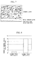
Fig. 4 andFig. 5 are scanning electron microscope (SEM) photographs of cross-sections of thermal barrier coatings prepared using the thermal spray particles A and the thermal spray particles B respectively.Fig. 6 andFig. 7 are images prepared by performing image processing of the SEM photographs ofFig. 4 andFig. 5 respectively, and illustrate fine defects (laminar defects) extending from pore origins. Measurement of the thickness of the ceramic layer withinFig. 4 andFig. 5 revealed a thickness of 470 µm for the ceramic layer of the thermal spray particles A and a thickness of 460 µm for the ceramic layer of the thermal spray particles B. - The thermal barrier coating test pieces prepared using the thermal spray particles A and the thermal spray particles B were measured for porosity of the ceramic layer, thermal conductivity, and the value of the above-mentioned ΔT as an indicator of the thermal cycling durability. The results are shown in Table 1.
The porosity was determined by using an image processing method to analyze microscope photographs of a finely polished cross-section of the thermal barrier coating acquired for 5 random fields of view (observation length: approximately 3 mm) using an optical microscope (magnification: 100×). The thermal conductivity was measured using the laser flash method prescribed in JIS R 1611.{Table 1} Thermal spray particles A Thermal spray particles B Porosity (%) 16 10 Thermal conductivity (kcal/mn°C) 0.9 1 ΔT (°C) 780 510 - The number of thermal cycles (relative value) endured when the above thermal barrier coating test pieces were subjected to a laser thermal cycling test under conditions including a maximum surface heating temperature of 1500°C, a maximum interface temperature of 900°C, a heating time of 3 minutes and a cooling time of 3 minutes are illustrated in
Fig. 8 . In this figure, the vertical axis represents the number of thermal cycles completed before destruction of the ceramic layer, reported relative to a value of 1 for the result obtained with the thermal spray particles B. - Compared with the ceramic layer formed using the thermal spray particles B, the ceramic layer formed using the thermal spray particles A has increased porosity and a thermal conductivity that is approximately 10% lower. This increase in the porosity within the ceramic layer formed using the thermal spray particles A is due to the removal of the small particles and the resulting increase in the average particle size.
- As illustrated in
Fig. 6 andFig. 7 , a plurality of laminar defects were observed in the ceramic layer formed using the thermal spray particles B. It is thought that this is due to the large proportion of fine particles within the thermal spray particles B. In contrast, in the ceramic layer formed using the thermal spray particles A, it was confirmed that because the proportion of fine particles was minimal, the occurrence of laminar defects was able to be suppressed.
As illustrated in Table 1 andFig. 8 , the thermal cycling durability increased dramatically for the thermal barrier coating formed using the thermal spray particles A. This result suggests that particles having a particle size of 40 µm or less contribute to the generation of laminar defects, and also that these laminar defects have an adverse effect on the thermal cycling durability of the coating.
Even when a ceramic layer of the thermal spray particles A was formed using different thermal spray conditions (such as a different spray distance), thermal cycling durability that was substantially equivalent to that illustrated in Table 1 andFig. 8 was obtained. This result suggests that the thermal spray conditions have almost no effect on the generation of laminar defects. - As described above, by using thermal spray particles in which the number of small particles (for example, particles having a particle size of 40 µm or less) has been dramatically reduced, the porosity of the ceramic layer can be increased, and a thermal barrier coating that exhibits superior thermal barrier properties and excellent thermal cycling durability can be obtained.
- Similarly, it has been confirmed that in the cases of YSZ and SmYbZr2O7 and the like, by forming a thermal barrier coating using thermal spray particles from which small particles have been removed in the same manner as that described above, the porosity of the ceramic layer increases and the thermal cycling durability improves.
-
- 11
- Heat-resistant alloy substrate
- 12
- Metal bonding layer
- 13
- Ceramic layer
Claims (4)
- A process for producing a thermal barrier coating, the process comprising:forming a metal bonding layer on a heat-resistant alloy substrate, andforming a ceramic layer on the metal bonding layer by thermal spraying of thermal spray particles having a particle size distribution in which a 10% cumulative particle size is not less than 30 µm and not more than 100 µm.
- The process for producing a thermal barrier coating according to claim 1, wherein
the thermal spray particles have a maximum particle size of not more than 150 µm, and comprise not more than 3% of particles having a particle size of 30 µm, and not more than 8% of particles having a particle size of 40 µm. - A turbine member, comprising a thermal barrier coating formed using the process according to claim 1 or claim 2.
- A gas turbine, comprising the turbine member according to claim 3.
Applications Claiming Priority (2)
| Application Number | Priority Date | Filing Date | Title |
|---|---|---|---|
| JP2009286659 | 2009-12-17 | ||
| PCT/JP2010/064691 WO2011074290A1 (en) | 2009-12-17 | 2010-08-30 | Method for producing a heat-shielding coating, turbine member provided with said heat-shielding coating, and gas turbine |
Publications (3)
| Publication Number | Publication Date |
|---|---|
| EP2514850A1 true EP2514850A1 (en) | 2012-10-24 |
| EP2514850A4 EP2514850A4 (en) | 2014-03-26 |
| EP2514850B1 EP2514850B1 (en) | 2017-07-26 |
Family
ID=44167057
Family Applications (1)
| Application Number | Title | Priority Date | Filing Date |
|---|---|---|---|
| EP10837321.8A Active EP2514850B1 (en) | 2009-12-17 | 2010-08-30 | Method for producing a heat-shielding coating, turbine member provided with said heat-shielding coating, and gas turbine |
Country Status (6)
| Country | Link |
|---|---|
| US (1) | US9822437B2 (en) |
| EP (1) | EP2514850B1 (en) |
| JP (1) | JP5602156B2 (en) |
| KR (2) | KR20140129392A (en) |
| CN (1) | CN102471863B (en) |
| WO (1) | WO2011074290A1 (en) |
Cited By (3)
| Publication number | Priority date | Publication date | Assignee | Title |
|---|---|---|---|---|
| EP3196329A4 (en) * | 2014-11-11 | 2017-10-18 | Mitsubishi Hitachi Power Systems, Ltd. | Heat shielding coating and turbine member |
| CN111926281A (en) * | 2020-09-03 | 2020-11-13 | 昆明理工大学 | Long-life spray gun ceramic coating for pizza smelting and preparation method thereof |
| EP4385967A1 (en) | 2022-12-14 | 2024-06-19 | Treibacher Industrie AG | Spray powder for high porosity coatings |
Families Citing this family (15)
| Publication number | Priority date | Publication date | Assignee | Title |
|---|---|---|---|---|
| CN103031555B (en) * | 2011-10-10 | 2016-12-07 | 深圳富泰宏精密工业有限公司 | Housing prepared by the preparation method of housing and the method |
| EP2644824A1 (en) * | 2012-03-28 | 2013-10-02 | Siemens Aktiengesellschaft | Method for producing and restoring of ceramic thermal barrier coatings in gas turbines and related gas turbine |
| CN103774082A (en) * | 2014-02-21 | 2014-05-07 | 北京矿冶研究总院 | Preparation method of thermal barrier coating |
| KR101909841B1 (en) * | 2014-09-05 | 2018-10-18 | 미츠비시 히타치 파워 시스템즈 가부시키가이샤 | Method for producing powder for thermal spray, apparatus for producing powder for thermal spray, and powder for thermal spray produced by said production method |
| KR20170102962A (en) * | 2015-02-12 | 2017-09-12 | 미츠비시 히타치 파워 시스템즈 가부시키가이샤 | Method for manufacturing a thermal coating, a turbine member, a gas turbine and a thermal coating |
| JP6908973B2 (en) * | 2016-06-08 | 2021-07-28 | 三菱重工業株式会社 | Manufacturing methods for thermal barrier coatings, turbine components, gas turbines, and thermal barrier coatings |
| US20210123124A1 (en) * | 2017-03-28 | 2021-04-29 | Mitsubishi Heavy Industries, Ltd. | Thermal barrier coating film and turbine member |
| JP7169077B2 (en) * | 2018-03-26 | 2022-11-10 | 三菱重工業株式会社 | Thermal barrier coating, turbine component, gas turbine, and method for producing thermal barrier coating |
| JP7045236B2 (en) * | 2018-03-27 | 2022-03-31 | 三菱重工業株式会社 | Thermal barrier coatings, turbine components and gas turbines |
| JP7372866B2 (en) | 2020-03-30 | 2023-11-01 | 三菱重工業株式会社 | Ceramic coatings, turbine parts and gas turbines |
| JP7686395B2 (en) * | 2020-12-28 | 2025-06-02 | 三菱重工航空エンジン株式会社 | Thermal barrier coating application method and heat-resistant member |
| JP7516293B2 (en) * | 2021-03-03 | 2024-07-16 | 株式会社東芝 | Heat-resistant components and power generation systems |
| JP7653837B2 (en) | 2021-05-20 | 2025-03-31 | 株式会社東芝 | Heat-resistant components and power generation systems |
| FR3136259B1 (en) * | 2022-06-03 | 2024-11-01 | Safran | ACOUSTIC PANEL FOR AN AIRCRAFT TURBOMACHINE, ASSOCIATED METHOD AND INSTALLATION |
| CN119238220B (en) * | 2024-09-28 | 2025-09-02 | 太原理工大学 | A method for barrel grinding and finishing of thermal barrier coatings in stages |
Family Cites Families (17)
| Publication number | Priority date | Publication date | Assignee | Title |
|---|---|---|---|---|
| JPS63131691A (en) | 1986-11-20 | 1988-06-03 | Nippon Tetsudo Kensetsu Kodan | Signal transmitter for remote supervisory and controlling equipment |
| JPH0516665A (en) * | 1991-07-17 | 1993-01-26 | Mitsubishi Heavy Ind Ltd | Vehicle air purifier |
| US6071627A (en) | 1996-03-29 | 2000-06-06 | Kabushiki Kaisha Toshiba | Heat-resistant member and a method for evaluating quality of a heat-resistant member |
| JP3372185B2 (en) | 1996-03-29 | 2003-01-27 | 株式会社東芝 | Heat resistant material |
| JPH1088368A (en) * | 1996-09-19 | 1998-04-07 | Toshiba Corp | Thermal barrier coating member and method of manufacturing the same |
| JP3872632B2 (en) | 2000-06-09 | 2007-01-24 | 三菱重工業株式会社 | Thermal barrier coating material, gas turbine member and gas turbine using the same |
| JP3631982B2 (en) | 2000-06-16 | 2005-03-23 | 三菱重工業株式会社 | Manufacturing method of thermal barrier coating material |
| JP3825231B2 (en) * | 2000-07-24 | 2006-09-27 | 三菱重工業株式会社 | Method for producing hollow ceramic powder for thermal spraying |
| JP4031631B2 (en) * | 2001-10-24 | 2008-01-09 | 三菱重工業株式会社 | Thermal barrier coating material, gas turbine member and gas turbine |
| JP2003160852A (en) | 2001-11-26 | 2003-06-06 | Mitsubishi Heavy Ind Ltd | Thermal barrier coating material, its manufacturing method, turbine member and gas turbine |
| US6866897B2 (en) * | 2002-09-30 | 2005-03-15 | General Electric Company | Method for manufacturing articles for high temperature use, and articles made therewith |
| CN1259453C (en) * | 2003-05-21 | 2006-06-14 | 中国科学院金属研究所 | Prepn of heat shock resisting heat barrier coating |
| JP4388466B2 (en) | 2004-12-27 | 2009-12-24 | 三菱重工業株式会社 | Gas turbine, thermal barrier coating material, manufacturing method thereof, and turbine member |
| JP4959213B2 (en) | 2006-03-31 | 2012-06-20 | 三菱重工業株式会社 | Thermal barrier coating member and manufacturing method thereof, thermal barrier coating material, gas turbine, and sintered body |
| CA2648643C (en) * | 2006-04-25 | 2015-07-07 | National Research Council Of Canada | Thermal spray coating of porous nanostructured ceramic feedstock |
| JP5034350B2 (en) * | 2006-07-25 | 2012-09-26 | 住友化学株式会社 | Method for producing zirconium oxide powder |
| US8053089B2 (en) * | 2009-09-30 | 2011-11-08 | General Electric Company | Single layer bond coat and method of application |
-
2010
- 2010-08-30 KR KR1020147029285A patent/KR20140129392A/en not_active Withdrawn
- 2010-08-30 US US13/387,206 patent/US9822437B2/en active Active
- 2010-08-30 KR KR1020127000591A patent/KR101618919B1/en active Active
- 2010-08-30 CN CN201080034127.5A patent/CN102471863B/en active Active
- 2010-08-30 JP JP2011546002A patent/JP5602156B2/en active Active
- 2010-08-30 EP EP10837321.8A patent/EP2514850B1/en active Active
- 2010-08-30 WO PCT/JP2010/064691 patent/WO2011074290A1/en not_active Ceased
Cited By (4)
| Publication number | Priority date | Publication date | Assignee | Title |
|---|---|---|---|---|
| EP3196329A4 (en) * | 2014-11-11 | 2017-10-18 | Mitsubishi Hitachi Power Systems, Ltd. | Heat shielding coating and turbine member |
| CN111926281A (en) * | 2020-09-03 | 2020-11-13 | 昆明理工大学 | Long-life spray gun ceramic coating for pizza smelting and preparation method thereof |
| EP4385967A1 (en) | 2022-12-14 | 2024-06-19 | Treibacher Industrie AG | Spray powder for high porosity coatings |
| WO2024126575A1 (en) | 2022-12-14 | 2024-06-20 | Treibacher Industrie Ag | Spray powder for high porosity coatings |
Also Published As
| Publication number | Publication date |
|---|---|
| EP2514850A4 (en) | 2014-03-26 |
| JP5602156B2 (en) | 2014-10-08 |
| KR20140129392A (en) | 2014-11-06 |
| US20130202912A1 (en) | 2013-08-08 |
| US9822437B2 (en) | 2017-11-21 |
| EP2514850B1 (en) | 2017-07-26 |
| CN102471863B (en) | 2014-07-09 |
| KR20120025592A (en) | 2012-03-15 |
| JPWO2011074290A1 (en) | 2013-04-25 |
| WO2011074290A1 (en) | 2011-06-23 |
| KR101618919B1 (en) | 2016-05-09 |
| CN102471863A (en) | 2012-05-23 |
Similar Documents
| Publication | Publication Date | Title |
|---|---|---|
| US9822437B2 (en) | Process for producing thermal barrier coating | |
| CA2529781C (en) | Thermal barrier coating material, thermal barrier member, and member coated with thermal barrier and method for manufacturing the same | |
| Wang et al. | Thermal cycling of EB-PVD TBCs based on YSZ ceramic coat and diffusion aluminide bond coat | |
| JP7174811B2 (en) | high temperature parts | |
| EP2009131A1 (en) | Heat shield coating member, process for producing the same, heat shield coat material, gas turbine and sintered body | |
| JP5622399B2 (en) | Thermal barrier coating, turbine member equipped with the same, and gas turbine | |
| JP2003160852A (en) | Thermal barrier coating material, its manufacturing method, turbine member and gas turbine | |
| Huang et al. | Effects of critical plasma spraying parameters on microstructure and mechanical properties of LaPO4-8YSZ thick composite coatings | |
| Zhu et al. | Microstructure and oxidation behavior of conventional and pseudo graded NiCrAlY/YSZ thermal barrier coatings produced by supersonic air plasma spraying process | |
| US20180030584A1 (en) | Thermal barrier coating, turbine member, gas turbine, and manufacturing method for thermal barrier coating | |
| US20080131608A1 (en) | Thermal barrier coating material, thermal barrier member, and member coated with thermal barrier and method for manufacturing the same | |
| Kumar | Comparison of thermal fatigue of superNi 718 SGTBCs and APSTBCs | |
| JP2009228018A (en) | Heat-shielding coating material, turbine member and gas turbine provided with the same, and method for manufacturing heat-shielding coating material | |
| US20110262770A1 (en) | Thermal barrier coating material, thermal barrier coating, turbine member, and gas turbine | |
| Saremi et al. | Bond coat oxidation and hot corrosion behavior of plasma sprayed YSZ coating on Ni superalloy | |
| EP3957827B1 (en) | A coating system for a component of a gas turbine engine | |
| Cheng et al. | Microstructure and thermal shock behaviors of APS Hf6Ta2O17-Ta2O5/YSZ double-ceramic top coat thermal barrier coatings | |
| JP2005163185A (en) | Gas turbine, thermal barrier coating material, its production method, and turbine member | |
| JP2007239101A (en) | Bond coating method for thermal barrier coating | |
| Manimaran et al. | Analysis of surface texture of Ni-based super alloy with thermal barrier coating system (TBC) for gas turbine blade | |
| JP2015218379A (en) | Thermal barrier coating material for steam turbine and steam equipment for power generation | |
| Rüßmann et al. | Thermal cycling tests of APS and SPS TBC systems on additively manufactured samples with cooling holes | |
| Min et al. | Fabrication and characterization of additive manufactured nickel-based ODS coating layer for high temperature application | |
| JP7516293B2 (en) | Heat-resistant components and power generation systems | |
| US20120270063A1 (en) | Thermal Barrier Coating Having Low Thermal Conductivity |
Legal Events
| Date | Code | Title | Description |
|---|---|---|---|
| PUAI | Public reference made under article 153(3) epc to a published international application that has entered the european phase |
Free format text: ORIGINAL CODE: 0009012 |
|
| 17P | Request for examination filed |
Effective date: 20120126 |
|
| AK | Designated contracting states |
Kind code of ref document: A1 Designated state(s): AL AT BE BG CH CY CZ DE DK EE ES FI FR GB GR HR HU IE IS IT LI LT LU LV MC MK MT NL NO PL PT RO SE SI SK SM TR |
|
| DAX | Request for extension of the european patent (deleted) | ||
| A4 | Supplementary search report drawn up and despatched |
Effective date: 20140224 |
|
| RIC1 | Information provided on ipc code assigned before grant |
Ipc: C23C 4/12 20060101ALI20140218BHEP Ipc: F01D 5/28 20060101ALI20140218BHEP Ipc: C23C 4/02 20060101ALI20140218BHEP Ipc: C23C 4/04 20060101ALI20140218BHEP Ipc: C23C 28/00 20060101ALI20140218BHEP Ipc: C23C 4/06 20060101ALI20140218BHEP Ipc: C23C 4/10 20060101AFI20140218BHEP |
|
| RAP1 | Party data changed (applicant data changed or rights of an application transferred) |
Owner name: MITSUBISHI HITACHI POWER SYSTEMS, LTD. |
|
| RAP1 | Party data changed (applicant data changed or rights of an application transferred) |
Owner name: MITSUBISHI HITACHI POWER SYSTEMS, LTD. |
|
| REG | Reference to a national code |
Ref country code: DE Ref legal event code: R079 Ref document number: 602010043960 Country of ref document: DE Free format text: PREVIOUS MAIN CLASS: C23C0004100000 Ipc: C23C0004110000 |
|
| RIC1 | Information provided on ipc code assigned before grant |
Ipc: C23C 4/04 20060101ALI20161219BHEP Ipc: C23C 28/00 20060101ALI20161219BHEP Ipc: C23C 4/02 20060101ALI20161219BHEP Ipc: C23C 4/06 20160101ALI20161219BHEP Ipc: C23C 4/11 20160101AFI20161219BHEP Ipc: F01D 5/28 20060101ALI20161219BHEP Ipc: C23C 4/134 20160101ALI20161219BHEP |
|
| GRAP | Despatch of communication of intention to grant a patent |
Free format text: ORIGINAL CODE: EPIDOSNIGR1 |
|
| INTG | Intention to grant announced |
Effective date: 20170215 |
|
| GRAS | Grant fee paid |
Free format text: ORIGINAL CODE: EPIDOSNIGR3 |
|
| GRAA | (expected) grant |
Free format text: ORIGINAL CODE: 0009210 |
|
| AK | Designated contracting states |
Kind code of ref document: B1 Designated state(s): AL AT BE BG CH CY CZ DE DK EE ES FI FR GB GR HR HU IE IS IT LI LT LU LV MC MK MT NL NO PL PT RO SE SI SK SM TR |
|
| REG | Reference to a national code |
Ref country code: GB Ref legal event code: FG4D |
|
| REG | Reference to a national code |
Ref country code: CH Ref legal event code: EP Ref country code: CH Ref legal event code: NV Representative=s name: E. BLUM AND CO. AG PATENT- UND MARKENANWAELTE , CH |
|
| REG | Reference to a national code |
Ref country code: AT Ref legal event code: REF Ref document number: 912467 Country of ref document: AT Kind code of ref document: T Effective date: 20170815 |
|
| REG | Reference to a national code |
Ref country code: IE Ref legal event code: FG4D |
|
| REG | Reference to a national code |
Ref country code: DE Ref legal event code: R096 Ref document number: 602010043960 Country of ref document: DE |
|
| REG | Reference to a national code |
Ref country code: NL Ref legal event code: MP Effective date: 20170726 |
|
| REG | Reference to a national code |
Ref country code: LT Ref legal event code: MG4D |
|
| REG | Reference to a national code |
Ref country code: AT Ref legal event code: MK05 Ref document number: 912467 Country of ref document: AT Kind code of ref document: T Effective date: 20170726 |
|
| PG25 | Lapsed in a contracting state [announced via postgrant information from national office to epo] |
Ref country code: FI Free format text: LAPSE BECAUSE OF FAILURE TO SUBMIT A TRANSLATION OF THE DESCRIPTION OR TO PAY THE FEE WITHIN THE PRESCRIBED TIME-LIMIT Effective date: 20170726 Ref country code: NL Free format text: LAPSE BECAUSE OF FAILURE TO SUBMIT A TRANSLATION OF THE DESCRIPTION OR TO PAY THE FEE WITHIN THE PRESCRIBED TIME-LIMIT Effective date: 20170726 Ref country code: HR Free format text: LAPSE BECAUSE OF FAILURE TO SUBMIT A TRANSLATION OF THE DESCRIPTION OR TO PAY THE FEE WITHIN THE PRESCRIBED TIME-LIMIT Effective date: 20170726 Ref country code: SE Free format text: LAPSE BECAUSE OF FAILURE TO SUBMIT A TRANSLATION OF THE DESCRIPTION OR TO PAY THE FEE WITHIN THE PRESCRIBED TIME-LIMIT Effective date: 20170726 Ref country code: NO Free format text: LAPSE BECAUSE OF FAILURE TO SUBMIT A TRANSLATION OF THE DESCRIPTION OR TO PAY THE FEE WITHIN THE PRESCRIBED TIME-LIMIT Effective date: 20171026 Ref country code: LT Free format text: LAPSE BECAUSE OF FAILURE TO SUBMIT A TRANSLATION OF THE DESCRIPTION OR TO PAY THE FEE WITHIN THE PRESCRIBED TIME-LIMIT Effective date: 20170726 Ref country code: AT Free format text: LAPSE BECAUSE OF FAILURE TO SUBMIT A TRANSLATION OF THE DESCRIPTION OR TO PAY THE FEE WITHIN THE PRESCRIBED TIME-LIMIT Effective date: 20170726 |
|
| PG25 | Lapsed in a contracting state [announced via postgrant information from national office to epo] |
Ref country code: LV Free format text: LAPSE BECAUSE OF FAILURE TO SUBMIT A TRANSLATION OF THE DESCRIPTION OR TO PAY THE FEE WITHIN THE PRESCRIBED TIME-LIMIT Effective date: 20170726 Ref country code: PL Free format text: LAPSE BECAUSE OF FAILURE TO SUBMIT A TRANSLATION OF THE DESCRIPTION OR TO PAY THE FEE WITHIN THE PRESCRIBED TIME-LIMIT Effective date: 20170726 Ref country code: IS Free format text: LAPSE BECAUSE OF FAILURE TO SUBMIT A TRANSLATION OF THE DESCRIPTION OR TO PAY THE FEE WITHIN THE PRESCRIBED TIME-LIMIT Effective date: 20171126 Ref country code: BG Free format text: LAPSE BECAUSE OF FAILURE TO SUBMIT A TRANSLATION OF THE DESCRIPTION OR TO PAY THE FEE WITHIN THE PRESCRIBED TIME-LIMIT Effective date: 20171026 Ref country code: ES Free format text: LAPSE BECAUSE OF FAILURE TO SUBMIT A TRANSLATION OF THE DESCRIPTION OR TO PAY THE FEE WITHIN THE PRESCRIBED TIME-LIMIT Effective date: 20170726 Ref country code: GR Free format text: LAPSE BECAUSE OF FAILURE TO SUBMIT A TRANSLATION OF THE DESCRIPTION OR TO PAY THE FEE WITHIN THE PRESCRIBED TIME-LIMIT Effective date: 20171027 |
|
| PG25 | Lapsed in a contracting state [announced via postgrant information from national office to epo] |
Ref country code: CZ Free format text: LAPSE BECAUSE OF FAILURE TO SUBMIT A TRANSLATION OF THE DESCRIPTION OR TO PAY THE FEE WITHIN THE PRESCRIBED TIME-LIMIT Effective date: 20170726 Ref country code: MC Free format text: LAPSE BECAUSE OF FAILURE TO SUBMIT A TRANSLATION OF THE DESCRIPTION OR TO PAY THE FEE WITHIN THE PRESCRIBED TIME-LIMIT Effective date: 20170726 Ref country code: RO Free format text: LAPSE BECAUSE OF FAILURE TO SUBMIT A TRANSLATION OF THE DESCRIPTION OR TO PAY THE FEE WITHIN THE PRESCRIBED TIME-LIMIT Effective date: 20170726 Ref country code: DK Free format text: LAPSE BECAUSE OF FAILURE TO SUBMIT A TRANSLATION OF THE DESCRIPTION OR TO PAY THE FEE WITHIN THE PRESCRIBED TIME-LIMIT Effective date: 20170726 |
|
| REG | Reference to a national code |
Ref country code: DE Ref legal event code: R097 Ref document number: 602010043960 Country of ref document: DE |
|
| REG | Reference to a national code |
Ref country code: BE Ref legal event code: MM Effective date: 20170831 |
|
| REG | Reference to a national code |
Ref country code: IE Ref legal event code: MM4A |
|
| PG25 | Lapsed in a contracting state [announced via postgrant information from national office to epo] |
Ref country code: EE Free format text: LAPSE BECAUSE OF FAILURE TO SUBMIT A TRANSLATION OF THE DESCRIPTION OR TO PAY THE FEE WITHIN THE PRESCRIBED TIME-LIMIT Effective date: 20170726 Ref country code: SK Free format text: LAPSE BECAUSE OF FAILURE TO SUBMIT A TRANSLATION OF THE DESCRIPTION OR TO PAY THE FEE WITHIN THE PRESCRIBED TIME-LIMIT Effective date: 20170726 Ref country code: SM Free format text: LAPSE BECAUSE OF FAILURE TO SUBMIT A TRANSLATION OF THE DESCRIPTION OR TO PAY THE FEE WITHIN THE PRESCRIBED TIME-LIMIT Effective date: 20170726 |
|
| PLBE | No opposition filed within time limit |
Free format text: ORIGINAL CODE: 0009261 |
|
| STAA | Information on the status of an ep patent application or granted ep patent |
Free format text: STATUS: NO OPPOSITION FILED WITHIN TIME LIMIT |
|
| PG25 | Lapsed in a contracting state [announced via postgrant information from national office to epo] |
Ref country code: LU Free format text: LAPSE BECAUSE OF NON-PAYMENT OF DUE FEES Effective date: 20170830 |
|
| 26N | No opposition filed |
Effective date: 20180430 |
|
| REG | Reference to a national code |
Ref country code: FR Ref legal event code: ST Effective date: 20180607 |
|
| PG25 | Lapsed in a contracting state [announced via postgrant information from national office to epo] |
Ref country code: IE Free format text: LAPSE BECAUSE OF NON-PAYMENT OF DUE FEES Effective date: 20170830 |
|
| PG25 | Lapsed in a contracting state [announced via postgrant information from national office to epo] |
Ref country code: FR Free format text: LAPSE BECAUSE OF NON-PAYMENT OF DUE FEES Effective date: 20170926 Ref country code: BE Free format text: LAPSE BECAUSE OF NON-PAYMENT OF DUE FEES Effective date: 20170831 Ref country code: SI Free format text: LAPSE BECAUSE OF FAILURE TO SUBMIT A TRANSLATION OF THE DESCRIPTION OR TO PAY THE FEE WITHIN THE PRESCRIBED TIME-LIMIT Effective date: 20170726 |
|
| PG25 | Lapsed in a contracting state [announced via postgrant information from national office to epo] |
Ref country code: MT Free format text: LAPSE BECAUSE OF NON-PAYMENT OF DUE FEES Effective date: 20170830 |
|
| PG25 | Lapsed in a contracting state [announced via postgrant information from national office to epo] |
Ref country code: HU Free format text: LAPSE BECAUSE OF FAILURE TO SUBMIT A TRANSLATION OF THE DESCRIPTION OR TO PAY THE FEE WITHIN THE PRESCRIBED TIME-LIMIT; INVALID AB INITIO Effective date: 20100830 |
|
| PG25 | Lapsed in a contracting state [announced via postgrant information from national office to epo] |
Ref country code: CY Free format text: LAPSE BECAUSE OF NON-PAYMENT OF DUE FEES Effective date: 20170726 |
|
| PG25 | Lapsed in a contracting state [announced via postgrant information from national office to epo] |
Ref country code: MK Free format text: LAPSE BECAUSE OF FAILURE TO SUBMIT A TRANSLATION OF THE DESCRIPTION OR TO PAY THE FEE WITHIN THE PRESCRIBED TIME-LIMIT Effective date: 20170726 |
|
| PG25 | Lapsed in a contracting state [announced via postgrant information from national office to epo] |
Ref country code: TR Free format text: LAPSE BECAUSE OF FAILURE TO SUBMIT A TRANSLATION OF THE DESCRIPTION OR TO PAY THE FEE WITHIN THE PRESCRIBED TIME-LIMIT Effective date: 20170726 |
|
| PG25 | Lapsed in a contracting state [announced via postgrant information from national office to epo] |
Ref country code: PT Free format text: LAPSE BECAUSE OF FAILURE TO SUBMIT A TRANSLATION OF THE DESCRIPTION OR TO PAY THE FEE WITHIN THE PRESCRIBED TIME-LIMIT Effective date: 20170726 |
|
| PG25 | Lapsed in a contracting state [announced via postgrant information from national office to epo] |
Ref country code: AL Free format text: LAPSE BECAUSE OF FAILURE TO SUBMIT A TRANSLATION OF THE DESCRIPTION OR TO PAY THE FEE WITHIN THE PRESCRIBED TIME-LIMIT Effective date: 20170726 |
|
| REG | Reference to a national code |
Ref country code: DE Ref legal event code: R082 Ref document number: 602010043960 Country of ref document: DE Representative=s name: HENKEL & PARTNER MBB PATENTANWALTSKANZLEI, REC, DE Ref country code: DE Ref legal event code: R081 Ref document number: 602010043960 Country of ref document: DE Owner name: MITSUBISHI POWER, LTD., JP Free format text: FORMER OWNER: MITSUBISHI HITACHI POWER SYSTEMS, LTD., YOKOHAMA, JP |
|
| REG | Reference to a national code |
Ref country code: CH Ref legal event code: PFA Owner name: MITSUBISHI POWER, LTD., JP Free format text: FORMER OWNER: MITSUBISHI HITACHI POWER SYSTEMS, LTD., JP |
|
| PGFP | Annual fee paid to national office [announced via postgrant information from national office to epo] |
Ref country code: DE Payment date: 20250702 Year of fee payment: 16 |
|
| PGFP | Annual fee paid to national office [announced via postgrant information from national office to epo] |
Ref country code: IT Payment date: 20250722 Year of fee payment: 16 |
|
| PGFP | Annual fee paid to national office [announced via postgrant information from national office to epo] |
Ref country code: GB Payment date: 20250703 Year of fee payment: 16 |
|
| PGFP | Annual fee paid to national office [announced via postgrant information from national office to epo] |
Ref country code: CH Payment date: 20250901 Year of fee payment: 16 |