EP2514637A1 - Dispositif d'accès en hauteur escamotable - Google Patents
Dispositif d'accès en hauteur escamotable Download PDFInfo
- Publication number
- EP2514637A1 EP2514637A1 EP12161285A EP12161285A EP2514637A1 EP 2514637 A1 EP2514637 A1 EP 2514637A1 EP 12161285 A EP12161285 A EP 12161285A EP 12161285 A EP12161285 A EP 12161285A EP 2514637 A1 EP2514637 A1 EP 2514637A1
- Authority
- EP
- European Patent Office
- Prior art keywords
- ladder
- access device
- indexing means
- retractable
- uprights
- Prior art date
- Legal status (The legal status is an assumption and is not a legal conclusion. Google has not performed a legal analysis and makes no representation as to the accuracy of the status listed.)
- Granted
Links
- 229910000831 Steel Inorganic materials 0.000 description 1
- 239000011248 coating agent Substances 0.000 description 1
- 238000000576 coating method Methods 0.000 description 1
- 230000007423 decrease Effects 0.000 description 1
- 238000009434 installation Methods 0.000 description 1
- 239000000463 material Substances 0.000 description 1
- 239000010959 steel Substances 0.000 description 1
Images

Classifications
-
- B—PERFORMING OPERATIONS; TRANSPORTING
- B60—VEHICLES IN GENERAL
- B60R—VEHICLES, VEHICLE FITTINGS, OR VEHICLE PARTS, NOT OTHERWISE PROVIDED FOR
- B60R3/00—Arrangements of steps or ladders facilitating access to or on the vehicle, e.g. running-boards
- B60R3/007—Removable steps or ladders, e.g. foldable
Definitions
- the technical field of the invention is that retractable height access devices for vehicles.
- the installation or deployment of the ladder must be possible from the top as well as from the bottom of the vehicle.
- the access device must also make it possible to cross fragile or dangerous areas (moving parts for example) of the walls of the vehicle without hindrance.
- This device poses a congestion problem. It does not allow to have a compactness that does not significantly change the size of the vehicle. In addition, this solution is complex because it requires a supply of hydraulic energy.
- the invention relates to a retractable height access device secured to a wall of a vehicle, retractable access device characterized in that it comprises a left scale and a straight ladder contiguous each comprising a left amount and a straight amount connected by bars, all the amounts being parallel between them, the left scale and the right scale being linked together by at least one articulation linking the left amount of the right scale and the right amount of the left scale, one of the two scales, called the pivoting scale, being furthermore linked to the wall of the vehicle at its other upright by at least one hinge of axis of rotation parallel to the uprights, the other ladder, called the adjacent ladder, comprising an indexing means allowing the locking of this adjoining ladder relative to the wall according to at least one locking position.
- the adjacent ladder comprises at least one sliding pivot connection at the level of the unbound amount to the other ladder, sliding pivot link secured to the wall and perpendicular to the uprights.
- the indexing means comprises at least one piercing corresponding to a locking position, pierced by a piercing rod integral with the adjacent ladder.
- the two scales are coplanar when the indexing means is on a first locking position.
- the two scales form an angle between them when the indexing means is on a second locking position.
- the indexing means is integral with at least one pivot-sliding connection.
- the indexing means is unlocked or locked using a control means operable from the top of the device as the bottom of the device.
- control means is constituted by the rod which comprises gripping means at each of its upper and lower ends.
- the device comprises at least one maneuvering pallet placed in the vicinity of an axis of rotation of the articulation between the scales.
- each ladder has handles parallel to the uprights and secured to the bars of the ladder in question.
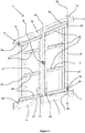
- a vertical wall (wall not shown) of a shielded vehicle comprises a retractable height access device 1.
- This device 1 is made integral with the wall by means of bolts or screws placed in the bores of mounting plates 4,5,6 and 7.
- the planes of the plates allow the figures to materialize the wall on which they are fixed .
- the device 1 comprises two scales 2 and 3, a right scale 3 and a left scale 2.
- Each scale 2 and 3 comprises two vertical uprights: the uprights 21 and 22 for the left scale 2 and the uprights 31 and 32 for the straight ladder 3. Bars 60 are perpendicular to the various amounts.
- the left scale 2 is linked to the right scale 3 by a hinge 8 connecting the right upright 21 of the left scale 2 to the left upright 31 of the right scale 3.
- This hinge 8 comprises an axis of rotation 81 parallel to the amounts 21,22,31,32.
- each of the adjacent ends of the left post 22 of the scale comprises a hinge 9a and 9b of axis 9 parallel to the amounts 21,22,31,32.
- These hinges 9a and 9b are each secured to a plate 4 or 6 solidarisant the device to the vehicle wall.
- the left scale 2 will be qualified subsequently as a pivoting ladder 2.
- the right-hand scale 3 which will subsequently be referred to as the ladder adjacent to the pivoting ladder 2, comprises a sliding pivot connection 18 and 19 in the vicinity of each upper and lower end of the right upright 32.
- the sliding pivot links 18 and 19 have an axis of rotation 30 parallel to the uprights. This axis 30 is, according to the embodiment shown, formed by a rod 13.
- Each of the sliding pivot links 18 and 19 comprises a slideway 10 or 11 which is perpendicular to the uprights 21,22,31,32 of the ladders 2 and 3.
- the figure 3 allows to see more precisely the structure of one of the slides.
- Each of the slides 10 and 11 comprises a groove 12A in which the rod 13 slides in a direction perpendicular to the axis 30 of the rod 13.
- Each of the sliding pivot links 18 and 19 is integral with the vehicle wall via the turntables 5 or 7.
- an indexing means 12 is integral with at least one of the slides 10 or 11, in the occurrence slide lower 11. According to another embodiment not shown, the slide and the indexing means can be dissociated.
- the indexing means 12 can be actuated by means of a control means 13 which makes it possible to unlock it.
- the control means 13 is constituted by the rod 13 itself which has at each of its ends a gripping means 14 or 15, for example a handle. These gripping means 14 and 15 make it possible to actuate the control rod 13 from the bottom or from the top of the device 1.
- the rod 13 acts as control means 13 and also materializes the axis of rotation 30 for the sliding pins 18 and 19.
- Maneuvering pallets 16 and 17 are placed on the pivoting ladder 2 at each of its upper and lower ends. These maneuvering pallets 16 and 17 are located in the vicinity of the axis of rotation 81 of the hinge 8 connecting the uprights 21 and 31 of the pivoting ladder 2 and the adjacent ladder 3 (thus close to the right upright 21 of the pivoting ladder 2).
- the device 1 In the retracted position, the device 1 only forms an extra thickness of about 55 mm with respect to the wall, which makes it possible to easily register the device 1 in the vehicle's road gauge.
- the scales 2 and 3 have a generally trapezoidal shape. This optimizes the size of the device 1 by adapting the shape of the upper ends of the two scales to the lateral profile of the vehicle which may include an inclined plane.
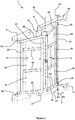
- the figure 2 shows the device 1 placed in the deployed position. In this position the two scales 2 and 3 are no longer coplanar and form an angle ⁇ between them allowing a user (not shown) to place his feet and hands to climb on the scales 2 and 3.
- the deployment of the device 1 is obtained from the top or bottom of the device 1.
- the user must operate one of the gripping means 14 or 15 to unlock the indexing means 12 of a first locking position P1 (locking in the retracted position shown in figure 1 ).
- the operator pulls one of the maneuvering pallets 16 or 17 so as to move the ladders 2 and 3 away from the wall. In this way each of the ladders 2 and 3 pivots. In doing so, the rod 13 also operates a translation along the slides 10 and 11.
- the so-called adjacent scale 3 pivots and its right amount 32 slides with a stroke C of the first locking position P1 to a second position of P2 lock (the one shown figure 2 ).
- the operator can then again operate one of the gripping means 14 or 15 in order to block the indexing means 12 in the second locking position P2.
- the device is then ready to allow the ascent or descent of the vehicle wall.
- the angle ⁇ decreases as the stroke C increases between the first locking position P1 and the second locking position P2.
- the scales 2 and 3 here have the same width.
- the width of each scale 2 and 3 may be chosen different so as to adapt the device to an opening geometry or a desired stroke C.
- Vertical holding handles 40 and 50 connect the consecutive bars 60 of each of the ladders 2 and 3. These handles 40 and 50 have a thickness less than or equal to that of the scales 2 and 3. They therefore do not form an extra thickness of a on either side of the scale 2 or 3. These handles 40 and 50 allow the user to progress more comfortably along the ladders 2 and 3, without putting their hands on the bars 60 which can be covered with an anti-slip coating of an abrasive nature.
- the figure 3 shows in detail an embodiment of the indexing means 12, positioned at the lower slide 11.
- the slide 11 comprises the groove 12A of a length equivalent to the stroke C between the two locking positions P1 and P2.
- the groove 12A has two holes 12B and 12C placed at the ends of the groove 12A and corresponding to the positions P1 and P2. These holes 12B and 12C have a diameter greater than the width L of the groove 12A.
- the control rod 13 which has a diameter D equal to that of the holes 12B and 12C, is housed in one or other of these holes.
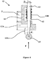
- the rod 13 comprises, in the vicinity of the indexing means 12, a portion 13A of reduced diameter d less than the width L of the groove 12A.
- the user moves the rod 13 in the vertical direction F to position the reduced diameter portion 13A at the groove 12A.
- the rod 13 can then slide along the slide 11.
- the pivoting of the adjacent ladder 3 is provided here thanks to a pivoting yoke 61 which can pivot on the rod 13 during the translation thereof.
- a pivoting yoke 61 which can pivot on the rod 13 during the translation thereof.
- the upper slide 10 may comprise an indexing means of similar structure. Fixing the adjacent ladder 3 is also performed at the upper slide by a yoke pivotally mounted on the rod 13.
- the device will preferably be made of steel or rigid plastic materials.
Landscapes
- Engineering & Computer Science (AREA)
- Mechanical Engineering (AREA)
- Ladders (AREA)
Abstract
Description
- Le domaine technique de l'invention est celui des dispositifs d'accès en hauteur escamotables pour véhicules.
- L'accès aux parties hautes de certains véhicules au gabarit imposant est souvent délicat du fait même de ce gabarit. Cependant cet accès est souvent indispensable par exemple pour permettre à un pilote de char ou d'engin de travaux publics de pouvoir accéder à son poste de pilotage.
- Pour cela il est classique d'utiliser une échelle. Cette échelle doit pouvoir être disponible à tout moment à l'extérieur du véhicule or son volume risque d'augmenter le gabarit routier du véhicule.
- De plus la mise en place ou le déploiement de l'échelle doit pouvoir se faire depuis le haut comme depuis le bas du véhicule. Le dispositif d'accès doit aussi permettre de franchir des zones fragiles ou dangereuses (parties mobiles par exemple) des parois du véhicule sans encombre.
- Il est connu dans le brevet
US5988316 d'accéder au poste de conduite d'un engin chenillé de travaux publics avec une échelle pivotante actionnée par un vérin. Le vérin a pour rôle de lever ou d'abaisser l'échelle suivant les besoins d'embarquement ou de débarquement. - Ce dispositif pose un problème d'encombrement. Il ne permet pas d'avoir une compacité ne modifiant pas de manière significative le gabarit du véhicule. En outre cette solution est complexe car elle requiert un apport en énergie hydraulique.
- Ainsi l'invention à pour objet un dispositif d'accès en hauteur escamotable solidaire d'une paroi d'un véhicule, dispositif d'accès escamotable caractérisé en ce qu'il comporte une échelle gauche et une échelle droite contiguës comportant chacune un montant gauche et un montant droit reliés par des barreaux, tous les montants étant parallèles entre eux, l'échelle gauche et l'échelle droite étant liées entre elles par au moins une articulation liant le montant gauche de l'échelle droite et le montant droit de l'échelle gauche, une des deux échelles, dite échelle pivotante, étant par ailleurs liée à la paroi du véhicule au niveau de son autre montant par au moins une charnière d'axe de rotation parallèle aux montants, l'autre échelle, dite échelle attenante, comportant un moyen d'indexation permettant le verrouillage de cette échelle attenante par rapport à la paroi suivant au moins une position de verrouillage.
- Selon une caractéristique de l'invention, l'échelle attenante comporte au moins une liaison pivot glissant au niveau du montant non lié à l'autre échelle, liaison pivot glissant solidaire de la paroi et perpendiculaire aux montants.
- Avantageusement, le moyen d'indexation comporte au moins un perçage correspondant à une position de verrouillage, perçage traversé par une tringle solidaire de l'échelle attenante.
- Avantageusement, les deux échelles sont coplanaires lorsque le moyen d'indexation est sur une première position de verrouillage.
- Avantageusement, les deux échelles forment un angle entre elles lorsque le moyen d'indexation est sur une seconde position de verrouillage.
- Selon une caractéristique de l'invention, le moyen d'indexation est solidaire d'au moins une liaison pivot-glissant.
- Avantageusement, le moyen d'indexation est déverrouillé ou verrouillé à l'aide d'un moyen de commande actionnable du haut du dispositif comme du bas du dispositif.
- Avantageusement, le moyen de commande est constitué par la tringle qui comporte des moyens de préhension à chacune de ses extémités supérieure et inférieure.
- Selon une caractéristique de l'invention le dispositif comporte au moins une palette de manoeuvre placée au voisinage d'un axe de rotation de l'articulation entre les échelles.
- Selon une caractéristique de l'invention, chaque échelle comporte des poignées parallèles aux montants et solidaires des barreaux de l'échelle considérée.
- L'invention sera mieux comprise à la lecture de la description suivante, description faite en références aux figures annexées dans lesquelles:
- La
figure 1 représente un dispositif d'accès escamoté en vue en perspective de trois quarts. - La
figure 2 représente un dispositif d'accès déployé en vue en perspective de trois quarts. - La
figure 3 est une vue de détails montrant une liaison pivot glissant et un moyen d'indexation. - La
figure 4 représente une vue de détail du moyen d'indexation avec coupe partielle. - Selon la
figure 1 , une paroi verticale (paroi non représentée) d'un véhicule blindé comporte un dispositif d'accès en hauteur escamotable 1. - Ce dispositif 1 est rendu solidaire de la paroi au moyen de boulons ou vis mis en place dans les perçages de platines de fixation 4,5,6 et 7. Les plans des platines permettent sur les figures de matérialiser la paroi sur laquelle elles sont fixées.
- Le dispositif 1 comporte deux échelles 2 et 3, une échelle droite 3 et une échelle gauche 2. Chaque échelle 2 et 3 comporte deux montants verticaux: les montants 21 et 22 pour l'échelle gauche 2 et les montants 31 et 32 pour l'échelle droite 3. Des barreaux 60 sont perpendiculaires aux différents montants.
- L'échelle gauche 2 est liée à l'échelle droite 3 par une articulation 8 reliant le montant droit 21 de l'échelle de gauche 2 au montant gauche 31 de l'échelle de droite 3. Cette articulation 8 comporte un axe de rotation 81 parallèle aux montants 21,22,31,32.
- Sur l'échelle gauche 2, chacune des extrémités voisines du montant gauche 22 de l'échelle, comporte une charnière 9a et 9b d'axe 9 parallèle aux montants 21,22,31,32. Ces charnières 9a et 9b sont chacune solidaire d'une platine 4 ou 6 solidarisant le dispositif à la paroi du véhicule. Pour le mode de réalisation qui est ici décrit l'échelle de gauche 2 sera qualifiée par la suite d'échelle pivotante 2.
- L'échelle de droite 3, qui sera par la suite qualifiée d'échelle attenante à l'échelle pivotante 2, comporte une liaison pivot glissant 18 et 19 au voisinage de chaque extrémité supérieure et inférieure du montant de droite 32. Les liaisons pivots glissants 18 et 19 comportent un axe de rotation 30 parallèle aux montants. Cet axe 30 est, selon le mode de réalisation représenté, formé par une tringle 13. Chacune des liaisons pivot glissant 18 et 19 comporte une glissière 10 ou 11 qui est perpendiculaire aux montants 21,22,31,32 des échelles 2 et 3.
- La
figure 3 permet de voir plus précisément la structure d'une des glissières. - Chacune des glissières 10 et 11 comporte une rainure 12A dans laquelle coulisse la tringle 13 suivant une direction perpendiculaire à l'axe 30 de la tringle 13. Chacune des liaisons pivot glissant 18 et 19 est solidaire de la paroi du véhicule par l'intermédiaire des platines 5 ou 7.
- On notera que sur la
figure 1 les deux échelles 2 et 3 sont coplanaires, ce qui correspond à la position escamotée du dispositif 1. Afin d'être maintenue dans cette position escamotée, un moyen d'indexation 12 est solidaire d'au moins une des glissières 10 ou 11, en l'occurrence la glissière inférieure 11. Selon un autre mode de réalisation non représenté, la glissière et le moyen d'indexation peuvent être dissociés. - Le moyen d'indexation 12 est actionnable à l'aide d'un moyen de commande 13 qui permet de le déverrouiller. Le moyen de commande 13 est ici constitué par la tringle 13 elle-même qui dispose à chacune de ses extrémités d'un moyen de préhension 14 ou 15, par exemple une poignée. Ces moyens de préhensions 14 et 15 permettent d'actionner la tringle de commande 13 depuis le bas ou depuis le haut du dispositif 1.
- On notera que dans le mode de réalisation représenté, la tringle 13 fait office de moyen de commande 13 et matérialise aussi l'axe de rotation 30 pour les pivots glissant 18 et 19.
- Des palettes de manoeuvre 16 et 17 sont placées sur l'échelle pivotante 2 à chacune de ses extrémités haute et basse. Ces palettes de manoeuvre 16 et 17 sont situées au voisinage de l'axe de rotation 81 de l'articulation 8 reliant les montants 21 et 31 de l'échelle pivotante 2 et de l'échelle attenante 3 (donc à proximité du montant droit 21 de l'échelle pivotante 2).
- Dans la position escamotée, le dispositif 1 ne forme qu'une surépaisseur de l'ordre de 55mm par rapport à la paroi ce qui permet d'inscrire facilement le dispositif 1 dans le gabarit routier du véhicule. On notera que les échelles 2 et 3 ont une forme générale trapézoïdale. Ceci permet d'optimiser l'encombrement du dispositif 1 en l'adaptant la forme des extrémités supérieures des deux échelles au profil latéral du véhicule qui pourra comporter un plan incliné.
- La
figure 2 montre le dispositif 1 placé en position déployée. Dans cette position les deux échelles 2 et 3 ne sont plus coplanaires et forment entre elles un angle α permettant à un utilisateur (non représenté) de placer ses pieds et ses mains pour monter sur les échelles 2 et 3. Le déploiement du dispositif 1 est obtenu depuis le haut ou le bas du dispositif 1. Pour cela l'utilisateur doit actionner un des moyens de préhension 14 ou 15 afin de débloquer le moyen d'indexation 12 d'une première position de verrouillage P1 (verrouillage en position escamotée représentée à lafigure 1 ). Simultanément l'opérateur tire une des palettes de manoeuvre 16 ou 17 de manière à éloigner les échelles 2 et 3 de la paroi. De cette manière chacune des échelles 2 et 3 pivote. Ce faisant, la tringle 13 opère aussi une translation le long des glissières 10 et 11. L'échelle dite attenante 3 pivote et son montant de droite 32 glisse avec une course C de la première position de verrouillage P1 jusqu'à une seconde position de verrouillage P2 (celle représentéefigure 2 ). L'opérateur peut alors de nouveau actionner un des moyens de préhension 14 ou 15 afin de bloquer le moyen d'indexation 12 dans la seconde position de verrouillage P2. Le dispositif est alors prêt pour permettre l'ascension ou la descente de la paroi du véhicule. - L'angle α diminue lorsque la course C augmente entre la première position de verrouillage P1 et la seconde position de verrouillage P2. Les échelles 2 et 3 ont ici la même largeur. La largeur de chaque échelle 2 et 3 pourra être choisie différente de manière à adapter le dispositif à une géométrie d'ouverture ou à une course C souhaitée.
- Des poignées de maintien verticales 40 et 50 relient les barreaux 60 consécutifs de chacune des échelles 2 et 3. Ces poignées 40 et 50 ont une épaisseur inférieure ou égale à celle des échelles 2 et 3. Elles ne forment donc pas de surépaisseur d'un coté ou de l'autre de l'échelle 2 ou 3. Ces poignées 40 et 50 permettent à l'utilisateur de progresser plus confortablement le long des échelles 2 et 3, sans poser les mains sur les barreaux 60 qui pourront être recouverts d'un revêtement antidérapant de nature abrasive.
- La
figure 3 montre de façon détaillée un exemple de réalisation du moyen d'indexation 12, positionné au niveau de la glissière inférieure 11. - La glissière 11 comporte la rainure 12A d'une longueur équivalente à la course C entre les deux positions de verrouillage P1 et P2. La rainure 12A comporte deux perçages 12B et 12C placés aux extrémités de la rainure 12A et correspondant aux positions P1 et P2. Ces perçages 12B et 12C ont un diamètre supérieur à la largeur L de la rainure 12A. Pour bloquer le dispositif 1 en position escamotée ou déployée, la tringle de commande 13, qui a un diamètre D égal à celui des perçages 12B et 12C, est logée dans l'un ou l'autre de ces perçages.
- Comme on le voit à la
figure 4 , la tringle 13 comporte, au voisinage du moyen d'indexation 12, une portion 13A de diamètre réduit d inférieur à la largeur L de la rainure 12A. - Pour déverrouiller le dispositif 1, l'utilisateur déplace la tringle 13 suivant la direction verticale F jusqu'à positionner la portion de diamètre réduit 13A au niveau de la rainure 12A. La tringle 13 peut alors coulisser le long de la glissière 11.
- Le pivotement de l'échelle attenante 3 est assuré ici grâce à une chape pivotante 61 qui peut pivoter sur la tringle 13 lors de la translation de cette dernière. Ainsi le pivotement/translation de l'échelle de droite 3 ou échelle attenante peut s'opérer telle que précédemment décrit.
- Lorsque la tringle 13 a parcouru la course C, elle se positionne automatiquement dans le perçage 12C grâce à un ressort de rappel 13B qui est monté dans la chape 61 et qui pousse une rondelle 62 solidaire de la tringle 13.
- La glissière supérieure 10 pourra comporter un moyen d'indexation de structure analogue. La fixation de l'échelle attenante 3 est également réalisée au niveau de la glissière supérieure par une chape montée pivotante sur la tringle 13. Le dispositif sera préférentiellement réalisé en acier ou dans des matériaux plastiques rigides.
Claims (10)
- Dispositif d'accès en hauteur (1) escamotable solidaire d'une paroi d'un véhicule, dispositif d'accès escamotable caractérisé en ce qu'il comporte une échelle gauche (2) et une échelle droite (3) contiguës comportant chacune un montant gauche (22,31) et un montant droit (21,32) reliés par des barreaux (60), tous les montants (21,22,31,32) étant parallèles entre eux, l'échelle gauche (2) et l'échelle droite (3) étant liées entre elles par au moins une articulation (8) liant le montant gauche (31) de l'échelle droite (3) et le montant droit (21) de l'échelle gauche (2), une des deux échelles (2), dite échelle pivotante, étant par ailleurs liée à la paroi du véhicule au niveau de son autre montant (21) par au moins une charnière (9a, 9b) d'axe de rotation (9) parallèle aux montants (21,22,31,32), l'autre échelle (3), dite échelle attenante (3), comportant un moyen d'indexation (12) permettant le verrouillage de cette échelle attenante (3) par rapport à la paroi suivant au moins une position de verrouillage.
- Dispositif d'accès escamotable (1) selon la revendication 1, caractérisé en ce que l'échelle attenante (3) comporte au moins une liaison pivot glissant (18,19) au niveau du montant (32) non lié à l'autre échelle (2), liaison pivot glissant (18,19) solidaire de la paroi et perpendiculaire aux montants (21,22,31,32).
- Dispositif d'accès escamotable (1) selon une des revendications 1 ou 2, caractérisé en ce que le moyen d'indexation (12) comporte au moins un perçage (12B,12C) correspondant à une position de verrouillage (P1,P2), perçage (12B,12C) traversé par une tringle (13) solidaire de l'échelle attenante (3).
- Dispositif d'accès escamotable (1) selon une des revendications 1 à 3, caractérisé en ce que les deux échelles (2 et 3) sont coplanaires lorsque le moyen d'indexation (12) est sur une première position de verrouillage (P1).
- Dispositif d'accès escamotable (1) selon une des revendications 1 à 4, caractérisé en ce que les deux échelles (2 et3) forment un angle (∝) entre elles lorsque le moyen d'indexation (12) est sur une seconde position (P2) de verrouillage.
- Dispositif d'accès escamotable (1) selon une des revendications 1 à 5, caractérisé en ce que le moyen d'indexation (12) est solidaire d'au moins une liaison pivot-glissant (18, 19)
- Dispositif d'accès escamotable (1) selon une des revendications 1 à 6, caractérisé en ce que le moyen d'indexation (12) est déverrouillé ou verrouillé à l'aide d'un moyen de commande (13) actionnable du haut du dispositif (1) comme du bas du dispositif (1).
- Dispositif d'accès escamotable (1) selon les revendications 3 et 7, caractérisé en ce que le moyen de commande (13) est constitué par la tringle (13) qui comporte des moyens de préhension (14,15) à chacune de ses extrémités supérieure et inférieure
- Dispositif d'accès escamotable (1) selon une des revendications 1 à 8, caractérisé en ce que le dispositif (1) comporte au moins une palette de manoeuvre (16) placée au voisinage d'un axe de rotation (81) de l'articulation (8) entre les échelles (2,3).
- Dispositif d'accès escamotable (1) selon une des revendications 1 à 9, caractérisé en ce que chaque échelle (2,3) comporte des poignées (40) parallèles aux montants (1) et solidaires des barreaux (60) de l'échelle (2,3) considérée.
Applications Claiming Priority (1)
| Application Number | Priority Date | Filing Date | Title |
|---|---|---|---|
| FR1101241A FR2974386B1 (fr) | 2011-04-20 | 2011-04-20 | Dispositif d'acces en hauteur escamotable |
Publications (2)
| Publication Number | Publication Date |
|---|---|
| EP2514637A1 true EP2514637A1 (fr) | 2012-10-24 |
| EP2514637B1 EP2514637B1 (fr) | 2013-11-20 |
Family
ID=45851445
Family Applications (1)
| Application Number | Title | Priority Date | Filing Date |
|---|---|---|---|
| EP12161285.7A Active EP2514637B1 (fr) | 2011-04-20 | 2012-03-26 | Dispositif d'accès en hauteur escamotable |
Country Status (3)
| Country | Link |
|---|---|
| EP (1) | EP2514637B1 (fr) |
| ES (1) | ES2443587T3 (fr) |
| FR (1) | FR2974386B1 (fr) |
Citations (1)
| Publication number | Priority date | Publication date | Assignee | Title |
|---|---|---|---|---|
| US5988316A (en) | 1996-02-27 | 1999-11-23 | Justoy Pty Ltd | Access device |
-
2011
- 2011-04-20 FR FR1101241A patent/FR2974386B1/fr not_active Expired - Fee Related
-
2012
- 2012-03-26 ES ES12161285T patent/ES2443587T3/es active Active
- 2012-03-26 EP EP12161285.7A patent/EP2514637B1/fr active Active
Patent Citations (1)
| Publication number | Priority date | Publication date | Assignee | Title |
|---|---|---|---|---|
| US5988316A (en) | 1996-02-27 | 1999-11-23 | Justoy Pty Ltd | Access device |
Also Published As
| Publication number | Publication date |
|---|---|
| ES2443587T3 (es) | 2014-02-19 |
| EP2514637B1 (fr) | 2013-11-20 |
| FR2974386A1 (fr) | 2012-10-26 |
| FR2974386B1 (fr) | 2013-04-12 |
Similar Documents
| Publication | Publication Date | Title |
|---|---|---|
| FR3018052A1 (fr) | Machine de travail, notamment camion a benne | |
| EP3095952B1 (fr) | Marchepied a tablette a hauteur reglable | |
| EP3450363B1 (fr) | Quai sécurisé de déchargement des déchets depuis un véhicule dans un centre de stockage | |
| FR3031716A1 (fr) | Chariot pour transporter une bicyclette | |
| EP2332660A1 (fr) | Dispositif de préparation d'au moins une vitre avant son montage dans un véhicule | |
| EP2514637B1 (fr) | Dispositif d'accès en hauteur escamotable | |
| EP3377397B1 (fr) | Véhicule de transport d'une charge | |
| FR3074157B1 (fr) | Equipement amovible d'acces pour intervention sur panneau en hauteur | |
| EP2404806A1 (fr) | Equipement mobile pour le transfert et le déplacement notamment de meubles | |
| EP3141517A1 (fr) | Grue a montage rapide et non autolestee | |
| EP1413696A1 (fr) | Banche en matériau composite | |
| EP2716498B1 (fr) | Installation d'accès sécurisé à une partie supérieure d'un véhicule | |
| FR3076287B1 (fr) | Dispositif de deversement lateral de matiere, notamment d'enrobes, et systeme le comprenant | |
| FR3121135A1 (fr) | Vehicule de transport de charges comportant un ensemble de deplacement d'une charge | |
| FR3103841A1 (fr) | Dispositif pour la construction de bâtiments et procédé pour la mise en œuvre de ce dispositif. | |
| EP2829501B1 (fr) | Dispositif de montage en porte-à-faux d'un chariot embarqué à l'arrière d'un véhicule porteur tel qu'un camion | |
| FR2926575A1 (fr) | Procede de montage et demontage en securite d'un echafaudage roulant, lisses de montage de securite utilisees et echafaudage obtenu | |
| EP1445153A2 (fr) | Véhicule équipé d'une barre anti-encastrement rétractable | |
| FR3043394B1 (fr) | Systeme d'embarquement d'un chariot elevateur sous une plateforme de chargement d'un vehicule de transport | |
| FR3152799A1 (fr) | Grue d'atelier multifonction | |
| FR2745596A1 (fr) | Element de barriere de separation de voies routieres et dispositif de manutention de tels elements | |
| FR3165879A1 (fr) | Table élévatrice pour la réparation et/ou la maintenance et/ou le contrôle d’engin roulant | |
| EP4619608A1 (fr) | Echelle à poste de travail repliable | |
| EP4056242A1 (fr) | Equipement pour la pratique du basketball | |
| EP1703072B1 (fr) | Echelle destinée à équiper une structure mobile |
Legal Events
| Date | Code | Title | Description |
|---|---|---|---|
| PUAI | Public reference made under article 153(3) epc to a published international application that has entered the european phase |
Free format text: ORIGINAL CODE: 0009012 |
|
| AK | Designated contracting states |
Kind code of ref document: A1 Designated state(s): AL AT BE BG CH CY CZ DE DK EE ES FI FR GB GR HR HU IE IS IT LI LT LU LV MC MK MT NL NO PL PT RO RS SE SI SK SM TR |
|
| AX | Request for extension of the european patent |
Extension state: BA ME |
|
| 17P | Request for examination filed |
Effective date: 20130424 |
|
| GRAP | Despatch of communication of intention to grant a patent |
Free format text: ORIGINAL CODE: EPIDOSNIGR1 |
|
| INTG | Intention to grant announced |
Effective date: 20130614 |
|
| GRAS | Grant fee paid |
Free format text: ORIGINAL CODE: EPIDOSNIGR3 |
|
| GRAA | (expected) grant |
Free format text: ORIGINAL CODE: 0009210 |
|
| AK | Designated contracting states |
Kind code of ref document: B1 Designated state(s): AL AT BE BG CH CY CZ DE DK EE ES FI FR GB GR HR HU IE IS IT LI LT LU LV MC MK MT NL NO PL PT RO RS SE SI SK SM TR |
|
| REG | Reference to a national code |
Ref country code: GB Ref legal event code: FG4D Free format text: NOT ENGLISH |
|
| REG | Reference to a national code |
Ref country code: CH Ref legal event code: EP |
|
| REG | Reference to a national code |
Ref country code: AT Ref legal event code: REF Ref document number: 641385 Country of ref document: AT Kind code of ref document: T Effective date: 20131215 |
|
| REG | Reference to a national code |
Ref country code: IE Ref legal event code: FG4D Free format text: LANGUAGE OF EP DOCUMENT: FRENCH |
|
| REG | Reference to a national code |
Ref country code: DE Ref legal event code: R096 Ref document number: 602012000531 Country of ref document: DE Effective date: 20140109 |
|
| REG | Reference to a national code |
Ref country code: ES Ref legal event code: FG2A Ref document number: 2443587 Country of ref document: ES Kind code of ref document: T3 Effective date: 20140219 |
|
| REG | Reference to a national code |
Ref country code: SE Ref legal event code: TRGR |
|
| REG | Reference to a national code |
Ref country code: NL Ref legal event code: VDEP Effective date: 20131120 |
|
| REG | Reference to a national code |
Ref country code: AT Ref legal event code: MK05 Ref document number: 641385 Country of ref document: AT Kind code of ref document: T Effective date: 20131120 |
|
| REG | Reference to a national code |
Ref country code: LT Ref legal event code: MG4D |
|
| PG25 | Lapsed in a contracting state [announced via postgrant information from national office to epo] |
Ref country code: NL Free format text: LAPSE BECAUSE OF FAILURE TO SUBMIT A TRANSLATION OF THE DESCRIPTION OR TO PAY THE FEE WITHIN THE PRESCRIBED TIME-LIMIT Effective date: 20131120 Ref country code: NO Free format text: LAPSE BECAUSE OF FAILURE TO SUBMIT A TRANSLATION OF THE DESCRIPTION OR TO PAY THE FEE WITHIN THE PRESCRIBED TIME-LIMIT Effective date: 20140220 Ref country code: LT Free format text: LAPSE BECAUSE OF FAILURE TO SUBMIT A TRANSLATION OF THE DESCRIPTION OR TO PAY THE FEE WITHIN THE PRESCRIBED TIME-LIMIT Effective date: 20131120 Ref country code: HR Free format text: LAPSE BECAUSE OF FAILURE TO SUBMIT A TRANSLATION OF THE DESCRIPTION OR TO PAY THE FEE WITHIN THE PRESCRIBED TIME-LIMIT Effective date: 20131120 Ref country code: IS Free format text: LAPSE BECAUSE OF FAILURE TO SUBMIT A TRANSLATION OF THE DESCRIPTION OR TO PAY THE FEE WITHIN THE PRESCRIBED TIME-LIMIT Effective date: 20140320 |
|
| PG25 | Lapsed in a contracting state [announced via postgrant information from national office to epo] |
Ref country code: RS Free format text: LAPSE BECAUSE OF FAILURE TO SUBMIT A TRANSLATION OF THE DESCRIPTION OR TO PAY THE FEE WITHIN THE PRESCRIBED TIME-LIMIT Effective date: 20131120 Ref country code: AT Free format text: LAPSE BECAUSE OF FAILURE TO SUBMIT A TRANSLATION OF THE DESCRIPTION OR TO PAY THE FEE WITHIN THE PRESCRIBED TIME-LIMIT Effective date: 20131120 Ref country code: LV Free format text: LAPSE BECAUSE OF FAILURE TO SUBMIT A TRANSLATION OF THE DESCRIPTION OR TO PAY THE FEE WITHIN THE PRESCRIBED TIME-LIMIT Effective date: 20131120 |
|
| PG25 | Lapsed in a contracting state [announced via postgrant information from national office to epo] |
Ref country code: PT Free format text: LAPSE BECAUSE OF FAILURE TO SUBMIT A TRANSLATION OF THE DESCRIPTION OR TO PAY THE FEE WITHIN THE PRESCRIBED TIME-LIMIT Effective date: 20140320 |
|
| PG25 | Lapsed in a contracting state [announced via postgrant information from national office to epo] |
Ref country code: EE Free format text: LAPSE BECAUSE OF FAILURE TO SUBMIT A TRANSLATION OF THE DESCRIPTION OR TO PAY THE FEE WITHIN THE PRESCRIBED TIME-LIMIT Effective date: 20131120 |
|
| REG | Reference to a national code |
Ref country code: DE Ref legal event code: R097 Ref document number: 602012000531 Country of ref document: DE |
|
| PG25 | Lapsed in a contracting state [announced via postgrant information from national office to epo] |
Ref country code: SK Free format text: LAPSE BECAUSE OF FAILURE TO SUBMIT A TRANSLATION OF THE DESCRIPTION OR TO PAY THE FEE WITHIN THE PRESCRIBED TIME-LIMIT Effective date: 20131120 Ref country code: RO Free format text: LAPSE BECAUSE OF FAILURE TO SUBMIT A TRANSLATION OF THE DESCRIPTION OR TO PAY THE FEE WITHIN THE PRESCRIBED TIME-LIMIT Effective date: 20131120 Ref country code: CZ Free format text: LAPSE BECAUSE OF FAILURE TO SUBMIT A TRANSLATION OF THE DESCRIPTION OR TO PAY THE FEE WITHIN THE PRESCRIBED TIME-LIMIT Effective date: 20131120 Ref country code: PL Free format text: LAPSE BECAUSE OF FAILURE TO SUBMIT A TRANSLATION OF THE DESCRIPTION OR TO PAY THE FEE WITHIN THE PRESCRIBED TIME-LIMIT Effective date: 20131120 |
|
| PLBE | No opposition filed within time limit |
Free format text: ORIGINAL CODE: 0009261 |
|
| STAA | Information on the status of an ep patent application or granted ep patent |
Free format text: STATUS: NO OPPOSITION FILED WITHIN TIME LIMIT |
|
| PG25 | Lapsed in a contracting state [announced via postgrant information from national office to epo] |
Ref country code: DK Free format text: LAPSE BECAUSE OF FAILURE TO SUBMIT A TRANSLATION OF THE DESCRIPTION OR TO PAY THE FEE WITHIN THE PRESCRIBED TIME-LIMIT Effective date: 20131120 |
|
| 26N | No opposition filed |
Effective date: 20140821 |
|
| PG25 | Lapsed in a contracting state [announced via postgrant information from national office to epo] |
Ref country code: LU Free format text: LAPSE BECAUSE OF FAILURE TO SUBMIT A TRANSLATION OF THE DESCRIPTION OR TO PAY THE FEE WITHIN THE PRESCRIBED TIME-LIMIT Effective date: 20140326 |
|
| REG | Reference to a national code |
Ref country code: DE Ref legal event code: R097 Ref document number: 602012000531 Country of ref document: DE Effective date: 20140821 |
|
| REG | Reference to a national code |
Ref country code: IE Ref legal event code: MM4A |
|
| PG25 | Lapsed in a contracting state [announced via postgrant information from national office to epo] |
Ref country code: IE Free format text: LAPSE BECAUSE OF NON-PAYMENT OF DUE FEES Effective date: 20140326 |
|
| PG25 | Lapsed in a contracting state [announced via postgrant information from national office to epo] |
Ref country code: SI Free format text: LAPSE BECAUSE OF FAILURE TO SUBMIT A TRANSLATION OF THE DESCRIPTION OR TO PAY THE FEE WITHIN THE PRESCRIBED TIME-LIMIT Effective date: 20131120 |
|
| REG | Reference to a national code |
Ref country code: FR Ref legal event code: PLFP Year of fee payment: 5 |
|
| PG25 | Lapsed in a contracting state [announced via postgrant information from national office to epo] |
Ref country code: MT Free format text: LAPSE BECAUSE OF FAILURE TO SUBMIT A TRANSLATION OF THE DESCRIPTION OR TO PAY THE FEE WITHIN THE PRESCRIBED TIME-LIMIT Effective date: 20131120 |
|
| PG25 | Lapsed in a contracting state [announced via postgrant information from national office to epo] |
Ref country code: SM Free format text: LAPSE BECAUSE OF FAILURE TO SUBMIT A TRANSLATION OF THE DESCRIPTION OR TO PAY THE FEE WITHIN THE PRESCRIBED TIME-LIMIT Effective date: 20131120 |
|
| PG25 | Lapsed in a contracting state [announced via postgrant information from national office to epo] |
Ref country code: MC Free format text: LAPSE BECAUSE OF FAILURE TO SUBMIT A TRANSLATION OF THE DESCRIPTION OR TO PAY THE FEE WITHIN THE PRESCRIBED TIME-LIMIT Effective date: 20131120 |
|
| PG25 | Lapsed in a contracting state [announced via postgrant information from national office to epo] |
Ref country code: CY Free format text: LAPSE BECAUSE OF FAILURE TO SUBMIT A TRANSLATION OF THE DESCRIPTION OR TO PAY THE FEE WITHIN THE PRESCRIBED TIME-LIMIT Effective date: 20131120 Ref country code: BG Free format text: LAPSE BECAUSE OF FAILURE TO SUBMIT A TRANSLATION OF THE DESCRIPTION OR TO PAY THE FEE WITHIN THE PRESCRIBED TIME-LIMIT Effective date: 20131120 Ref country code: GR Free format text: LAPSE BECAUSE OF FAILURE TO SUBMIT A TRANSLATION OF THE DESCRIPTION OR TO PAY THE FEE WITHIN THE PRESCRIBED TIME-LIMIT Effective date: 20140221 |
|
| PG25 | Lapsed in a contracting state [announced via postgrant information from national office to epo] |
Ref country code: HU Free format text: LAPSE BECAUSE OF FAILURE TO SUBMIT A TRANSLATION OF THE DESCRIPTION OR TO PAY THE FEE WITHIN THE PRESCRIBED TIME-LIMIT; INVALID AB INITIO Effective date: 20120326 Ref country code: BE Free format text: LAPSE BECAUSE OF FAILURE TO SUBMIT A TRANSLATION OF THE DESCRIPTION OR TO PAY THE FEE WITHIN THE PRESCRIBED TIME-LIMIT Effective date: 20140331 |
|
| REG | Reference to a national code |
Ref country code: FR Ref legal event code: PLFP Year of fee payment: 6 |
|
| REG | Reference to a national code |
Ref country code: FR Ref legal event code: PLFP Year of fee payment: 7 |
|
| PG25 | Lapsed in a contracting state [announced via postgrant information from national office to epo] |
Ref country code: MK Free format text: LAPSE BECAUSE OF FAILURE TO SUBMIT A TRANSLATION OF THE DESCRIPTION OR TO PAY THE FEE WITHIN THE PRESCRIBED TIME-LIMIT Effective date: 20131120 |
|
| PG25 | Lapsed in a contracting state [announced via postgrant information from national office to epo] |
Ref country code: AL Free format text: LAPSE BECAUSE OF FAILURE TO SUBMIT A TRANSLATION OF THE DESCRIPTION OR TO PAY THE FEE WITHIN THE PRESCRIBED TIME-LIMIT Effective date: 20131120 |
|
| PGFP | Annual fee paid to national office [announced via postgrant information from national office to epo] |
Ref country code: GB Payment date: 20220225 Year of fee payment: 11 Ref country code: FI Payment date: 20220215 Year of fee payment: 11 Ref country code: DE Payment date: 20220217 Year of fee payment: 11 Ref country code: CH Payment date: 20220218 Year of fee payment: 11 |
|
| PGFP | Annual fee paid to national office [announced via postgrant information from national office to epo] |
Ref country code: TR Payment date: 20220302 Year of fee payment: 11 Ref country code: SE Payment date: 20220217 Year of fee payment: 11 Ref country code: IT Payment date: 20220217 Year of fee payment: 11 Ref country code: FR Payment date: 20220218 Year of fee payment: 11 |
|
| PGFP | Annual fee paid to national office [announced via postgrant information from national office to epo] |
Ref country code: ES Payment date: 20220401 Year of fee payment: 11 |
|
| REG | Reference to a national code |
Ref country code: DE Ref legal event code: R119 Ref document number: 602012000531 Country of ref document: DE |
|
| PG25 | Lapsed in a contracting state [announced via postgrant information from national office to epo] |
Ref country code: FI Free format text: LAPSE BECAUSE OF NON-PAYMENT OF DUE FEES Effective date: 20230326 |
|
| REG | Reference to a national code |
Ref country code: SE Ref legal event code: EUG Ref country code: CH Ref legal event code: PL |
|
| GBPC | Gb: european patent ceased through non-payment of renewal fee |
Effective date: 20230326 |
|
| PG25 | Lapsed in a contracting state [announced via postgrant information from national office to epo] |
Ref country code: GB Free format text: LAPSE BECAUSE OF NON-PAYMENT OF DUE FEES Effective date: 20230326 |
|
| PG25 | Lapsed in a contracting state [announced via postgrant information from national office to epo] |
Ref country code: SE Free format text: LAPSE BECAUSE OF NON-PAYMENT OF DUE FEES Effective date: 20230327 Ref country code: LI Free format text: LAPSE BECAUSE OF NON-PAYMENT OF DUE FEES Effective date: 20230331 Ref country code: GB Free format text: LAPSE BECAUSE OF NON-PAYMENT OF DUE FEES Effective date: 20230326 Ref country code: FR Free format text: LAPSE BECAUSE OF NON-PAYMENT OF DUE FEES Effective date: 20230331 Ref country code: DE Free format text: LAPSE BECAUSE OF NON-PAYMENT OF DUE FEES Effective date: 20231003 Ref country code: CH Free format text: LAPSE BECAUSE OF NON-PAYMENT OF DUE FEES Effective date: 20230331 |
|
| PG25 | Lapsed in a contracting state [announced via postgrant information from national office to epo] |
Ref country code: IT Free format text: LAPSE BECAUSE OF NON-PAYMENT OF DUE FEES Effective date: 20230326 |
|
| REG | Reference to a national code |
Ref country code: ES Ref legal event code: FD2A Effective date: 20240508 |
|
| PG25 | Lapsed in a contracting state [announced via postgrant information from national office to epo] |
Ref country code: ES Free format text: LAPSE BECAUSE OF NON-PAYMENT OF DUE FEES Effective date: 20230327 |
|
| PG25 | Lapsed in a contracting state [announced via postgrant information from national office to epo] |
Ref country code: ES Free format text: LAPSE BECAUSE OF NON-PAYMENT OF DUE FEES Effective date: 20230327 |