EP2513563B1 - Tungsten carbide inserts for a gas turbine liner and method - Google Patents
Tungsten carbide inserts for a gas turbine liner and method Download PDFInfo
- Publication number
- EP2513563B1 EP2513563B1 EP10787777.1A EP10787777A EP2513563B1 EP 2513563 B1 EP2513563 B1 EP 2513563B1 EP 10787777 A EP10787777 A EP 10787777A EP 2513563 B1 EP2513563 B1 EP 2513563B1
- Authority
- EP
- European Patent Office
- Prior art keywords
- insert
- tungsten carbide
- shaped block
- wear
- metal matrix
- Prior art date
- Legal status (The legal status is an assumption and is not a legal conclusion. Google has not performed a legal analysis and makes no representation as to the accuracy of the status listed.)
- Not-in-force
Links
- UONOETXJSWQNOL-UHFFFAOYSA-N tungsten carbide Chemical compound [W+]#[C-] UONOETXJSWQNOL-UHFFFAOYSA-N 0.000 title claims description 32
- 238000000034 method Methods 0.000 title claims description 21
- 239000011159 matrix material Substances 0.000 claims description 27
- 238000005219 brazing Methods 0.000 claims description 23
- 229910052751 metal Inorganic materials 0.000 claims description 22
- 239000002184 metal Substances 0.000 claims description 22
- 239000000463 material Substances 0.000 claims description 18
- PXHVJJICTQNCMI-UHFFFAOYSA-N Nickel Chemical compound [Ni] PXHVJJICTQNCMI-UHFFFAOYSA-N 0.000 claims description 16
- 238000002485 combustion reaction Methods 0.000 claims description 14
- 230000007704 transition Effects 0.000 claims description 10
- 239000010941 cobalt Substances 0.000 claims description 9
- 229910017052 cobalt Inorganic materials 0.000 claims description 9
- GUTLYIVDDKVIGB-UHFFFAOYSA-N cobalt atom Chemical compound [Co] GUTLYIVDDKVIGB-UHFFFAOYSA-N 0.000 claims description 9
- 229910052759 nickel Inorganic materials 0.000 claims description 8
- 238000005245 sintering Methods 0.000 claims description 7
- 239000000203 mixture Substances 0.000 claims description 4
- -1 tungsten carbides Chemical class 0.000 claims description 3
- 229910052721 tungsten Inorganic materials 0.000 claims 1
- 239000010937 tungsten Substances 0.000 claims 1
- 239000000843 powder Substances 0.000 description 15
- 239000007789 gas Substances 0.000 description 14
- 238000000576 coating method Methods 0.000 description 10
- 239000011248 coating agent Substances 0.000 description 8
- 239000000446 fuel Substances 0.000 description 8
- 230000013011 mating Effects 0.000 description 8
- 239000000126 substance Substances 0.000 description 7
- 238000005507 spraying Methods 0.000 description 5
- 229910045601 alloy Inorganic materials 0.000 description 4
- 239000000956 alloy Substances 0.000 description 4
- 239000010953 base metal Substances 0.000 description 3
- BQCADISMDOOEFD-UHFFFAOYSA-N Silver Chemical compound [Ag] BQCADISMDOOEFD-UHFFFAOYSA-N 0.000 description 2
- 239000000567 combustion gas Substances 0.000 description 2
- 238000007689 inspection Methods 0.000 description 2
- 238000002844 melting Methods 0.000 description 2
- 230000008018 melting Effects 0.000 description 2
- 229920000642 polymer Polymers 0.000 description 2
- 229910052709 silver Inorganic materials 0.000 description 2
- 239000004332 silver Substances 0.000 description 2
- QVGXLLKOCUKJST-UHFFFAOYSA-N atomic oxygen Chemical compound [O] QVGXLLKOCUKJST-UHFFFAOYSA-N 0.000 description 1
- 238000005056 compaction Methods 0.000 description 1
- 238000001816 cooling Methods 0.000 description 1
- 238000000151 deposition Methods 0.000 description 1
- 238000000227 grinding Methods 0.000 description 1
- 238000002347 injection Methods 0.000 description 1
- 239000007924 injection Substances 0.000 description 1
- 238000005304 joining Methods 0.000 description 1
- 238000012423 maintenance Methods 0.000 description 1
- 230000007246 mechanism Effects 0.000 description 1
- 150000001247 metal acetylides Chemical class 0.000 description 1
- 238000002156 mixing Methods 0.000 description 1
- 230000003647 oxidation Effects 0.000 description 1
- 238000007254 oxidation reaction Methods 0.000 description 1
- 239000001301 oxygen Substances 0.000 description 1
- 229910052760 oxygen Inorganic materials 0.000 description 1
- 230000035515 penetration Effects 0.000 description 1
- 238000010248 power generation Methods 0.000 description 1
- 238000007493 shaping process Methods 0.000 description 1
- 239000007921 spray Substances 0.000 description 1
- 229910000601 superalloy Inorganic materials 0.000 description 1
- 238000005382 thermal cycling Methods 0.000 description 1
- 239000012855 volatile organic compound Substances 0.000 description 1
- 238000003466 welding Methods 0.000 description 1
Images






Classifications
-
- F—MECHANICAL ENGINEERING; LIGHTING; HEATING; WEAPONS; BLASTING
- F02—COMBUSTION ENGINES; HOT-GAS OR COMBUSTION-PRODUCT ENGINE PLANTS
- F02C—GAS-TURBINE PLANTS; AIR INTAKES FOR JET-PROPULSION PLANTS; CONTROLLING FUEL SUPPLY IN AIR-BREATHING JET-PROPULSION PLANTS
- F02C7/00—Features, components parts, details or accessories, not provided for in, or of interest apart form groups F02C1/00 - F02C6/00; Air intakes for jet-propulsion plants
- F02C7/20—Mounting or supporting of plant; Accommodating heat expansion or creep
-
- B—PERFORMING OPERATIONS; TRANSPORTING
- B32—LAYERED PRODUCTS
- B32B—LAYERED PRODUCTS, i.e. PRODUCTS BUILT-UP OF STRATA OF FLAT OR NON-FLAT, e.g. CELLULAR OR HONEYCOMB, FORM
- B32B15/00—Layered products comprising a layer of metal
- B32B15/04—Layered products comprising a layer of metal comprising metal as the main or only constituent of a layer, which is next to another layer of the same or of a different material
- B32B15/043—Layered products comprising a layer of metal comprising metal as the main or only constituent of a layer, which is next to another layer of the same or of a different material of metal
-
- B—PERFORMING OPERATIONS; TRANSPORTING
- B32—LAYERED PRODUCTS
- B32B—LAYERED PRODUCTS, i.e. PRODUCTS BUILT-UP OF STRATA OF FLAT OR NON-FLAT, e.g. CELLULAR OR HONEYCOMB, FORM
- B32B5/00—Layered products characterised by the non- homogeneity or physical structure, i.e. comprising a fibrous, filamentary, particulate or foam layer; Layered products characterised by having a layer differing constitutionally or physically in different parts
- B32B5/16—Layered products characterised by the non- homogeneity or physical structure, i.e. comprising a fibrous, filamentary, particulate or foam layer; Layered products characterised by having a layer differing constitutionally or physically in different parts characterised by features of a layer formed of particles, e.g. chips, powder or granules
-
- F—MECHANICAL ENGINEERING; LIGHTING; HEATING; WEAPONS; BLASTING
- F01—MACHINES OR ENGINES IN GENERAL; ENGINE PLANTS IN GENERAL; STEAM ENGINES
- F01D—NON-POSITIVE DISPLACEMENT MACHINES OR ENGINES, e.g. STEAM TURBINES
- F01D9/00—Stators
- F01D9/02—Nozzles; Nozzle boxes; Stator blades; Guide conduits, e.g. individual nozzles
-
- F—MECHANICAL ENGINEERING; LIGHTING; HEATING; WEAPONS; BLASTING
- F01—MACHINES OR ENGINES IN GENERAL; ENGINE PLANTS IN GENERAL; STEAM ENGINES
- F01D—NON-POSITIVE DISPLACEMENT MACHINES OR ENGINES, e.g. STEAM TURBINES
- F01D9/00—Stators
- F01D9/02—Nozzles; Nozzle boxes; Stator blades; Guide conduits, e.g. individual nozzles
- F01D9/023—Transition ducts between combustor cans and first stage of the turbine in gas-turbine engines; their cooling or sealings
-
- F—MECHANICAL ENGINEERING; LIGHTING; HEATING; WEAPONS; BLASTING
- F23—COMBUSTION APPARATUS; COMBUSTION PROCESSES
- F23R—GENERATING COMBUSTION PRODUCTS OF HIGH PRESSURE OR HIGH VELOCITY, e.g. GAS-TURBINE COMBUSTION CHAMBERS
- F23R3/00—Continuous combustion chambers using liquid or gaseous fuel
- F23R3/42—Continuous combustion chambers using liquid or gaseous fuel characterised by the arrangement or form of the flame tubes or combustion chambers
- F23R3/60—Support structures; Attaching or mounting means
-
- F—MECHANICAL ENGINEERING; LIGHTING; HEATING; WEAPONS; BLASTING
- F05—INDEXING SCHEMES RELATING TO ENGINES OR PUMPS IN VARIOUS SUBCLASSES OF CLASSES F01-F04
- F05D—INDEXING SCHEME FOR ASPECTS RELATING TO NON-POSITIVE-DISPLACEMENT MACHINES OR ENGINES, GAS-TURBINES OR JET-PROPULSION PLANTS
- F05D2230/00—Manufacture
- F05D2230/20—Manufacture essentially without removing material
- F05D2230/23—Manufacture essentially without removing material by permanently joining parts together
- F05D2230/232—Manufacture essentially without removing material by permanently joining parts together by welding
- F05D2230/237—Brazing
-
- F—MECHANICAL ENGINEERING; LIGHTING; HEATING; WEAPONS; BLASTING
- F05—INDEXING SCHEMES RELATING TO ENGINES OR PUMPS IN VARIOUS SUBCLASSES OF CLASSES F01-F04
- F05D—INDEXING SCHEME FOR ASPECTS RELATING TO NON-POSITIVE-DISPLACEMENT MACHINES OR ENGINES, GAS-TURBINES OR JET-PROPULSION PLANTS
- F05D2300/00—Materials; Properties thereof
- F05D2300/20—Oxide or non-oxide ceramics
- F05D2300/22—Non-oxide ceramics
- F05D2300/226—Carbides
- F05D2300/2263—Carbides of tungsten, e.g. WC
-
- Y—GENERAL TAGGING OF NEW TECHNOLOGICAL DEVELOPMENTS; GENERAL TAGGING OF CROSS-SECTIONAL TECHNOLOGIES SPANNING OVER SEVERAL SECTIONS OF THE IPC; TECHNICAL SUBJECTS COVERED BY FORMER USPC CROSS-REFERENCE ART COLLECTIONS [XRACs] AND DIGESTS
- Y10—TECHNICAL SUBJECTS COVERED BY FORMER USPC
- Y10T—TECHNICAL SUBJECTS COVERED BY FORMER US CLASSIFICATION
- Y10T428/00—Stock material or miscellaneous articles
- Y10T428/12—All metal or with adjacent metals
- Y10T428/12014—All metal or with adjacent metals having metal particles
- Y10T428/12028—Composite; i.e., plural, adjacent, spatially distinct metal components [e.g., layers, etc.]
- Y10T428/12063—Nonparticulate metal component
- Y10T428/12139—Nonmetal particles in particulate component
Definitions
- the embodiments of the subject matter disclosed herein generally relate to wear protection and more particularly to adding inserts to combustion hardware in gas turbine systems.
- Combustors are used in a gas turbine to deliver hot combustion gases to a first stage of a turbine.
- Each combustor used in the system typically includes a fuel injection system with one or more fuel nozzles and a combustion chamber.
- a typical combustion chamber may include a combustor liner, a transition piece which is connected to and extends between the combustion chamber and the first stage of the turbine, and a flow sleeve.
- a passage is created between the combustor liner and the flow sleeve which allows at least a portion of the compressor discharge air to be introduced into the combustor liner for mixing with the fuel injected into the system through the fuel nozzles and for cooling purposes.
- the transition piece directs and delivers the hot combustion gases to the first stage of the turbine for power generation and expansion.
- a combustor 2 for use in a gas turbine has a combustion chamber 4, which is inside of a combustion liner 6 which may be cylindrical in shape. Fuel enters the combustor chamber 4 via a nozzle(s) 12.
- the combustor liner 6 is surrounded by a substantially cylindrical flow sleeve 8.
- a radial gap exists between the combustor liner 6 and the cylindrical flow sleeve 8 which acts as an air flow passage to introduce air into the combustion chamber 4 to be mixed with the fuel delivered through the fuel nozzle 12.
- a transition piece 10 connects the combustor liner 6 with a first stage of a turbine (not shown). More information regarding a combustor for use in a gas turbine can be found in U.S. Patent Number 5,749,218 , entitled "Wear Reduction Kit for Gas Turbine Combustors".
- the document US 5 273 249 A shows a tungsten carbide wear reduction coating without a matrix material in a gas turbine.
- the document FR 2 924 465 A1 discloses turbine stator vanes made of tungsten carbide in a matrix material, but no brazed coating.
- the document EP 1 754 860 A2 shows a tungsten carbide in matrix material coating not brazed to a support structure, but applied to it via typical surface deposition methods.
- HVOF high velocity oxygen fuel
- the present invention provides a system and method as defined in the accompanying claims.
- various parts of the combustor can experience wear over time caused by, for example, vibration, when the gas turbine is in use.
- wear locations include, but are not limited to, various connectors, connection points and stops (see Figure 1 ) associated with the components of the combustor liner 6 and the transition piece 10, which are used in attaching the two components, as well as the mating points between the combustor liner 6 and the flow sleeve 8. More specifically, stops can be used to position, secure and ensure the desired radial spacing between the combustor liner 6 and the flow sleeve 8 at one end of the combustor liner 6.
- H-block connected to fingers is used at the other end of the combustor liner 6 to connect the combustor liner 6 with the transition piece 10.
- the H-block is also referred to herein as a "substantially H-shaped block” and an "H-shaped block”. Additionally, methods and systems for connecting these parts are generally known in the art, see, e.g., U.S. Patent Number 5,749,218 , and as such only an overview of the connection points is described to present context for the exemplary embodiments described herein.
- the wear characteristics of these contact points can be modified such that their useful lifetime is extended.
- Figures 2-5 will be described to provide context with respect to the components which tend to wear in a gas turbine combustion system.
- the transition piece 10 can have a flanged section 208 which has an opening 210.
- an H-shaped block 202 Within the opening 210 and attached to the flanged section 208 is an H-shaped block 202.
- the H-shaped block 202 can be attached to the flanged section 208 in various ways, such as, welding. While Figure 2 shows only a single H-shaped block 202 and a single flanged section 208, there may be two of these pieces/sections attached to the transition piece 10.
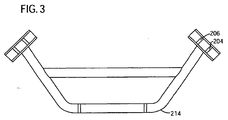
- Fingers 204 and 206 are slidably received within the H-shaped block 202 such that the opposed facing surfaces of the finger elements can engage opposite sides of the cross piece 212 of the H-shaped block 202. As shown in Figure 3 , fingers 204 and 206 are attached to a structural member 214 which is attached to a casing (not shown) which holds the combustor liner 6. Wear can occur on the interior surfaces of the H-shaped block 202 where the fingers 204 and 206 could rub or vibrate. Wear can also occur on the facing surfaces of the fingers 204 and 206 that contact the interior surfaces of the H-shaped block.
- Figure 4 shows the combustor liner 6 with an attached combustor liner stop 402. Numerous combustor liner stops 402 can be attached to the combustor liner 6 to position the combustor liner as desired.
- Figure 5 shows the combustor liner stop 402 and a male mating piece 404. The male mating piece is attached to the inside of the flow sleeve 8. Where these two pieces mate are also locations where wear can occur during operation of the combustor 2.
- the H-shaped blocks 202, the combustor liner stops 402 and their respective mating pieces can be made from a Cobalt based super alloy, e.g., L-605 or Hynes 25.
- tungsten carbide in a metal matrix e.g., cobalt or nickel
- the application of tungsten carbide in a metal matrix can increase the wear resistance of the various wear components, thus reducing the frequency of inspection and replacement of various wear components in a gas turbine combustor 2.
- the tungsten carbide in a metal matrix is formed into a desired shape for increasing the usable life of the part by, for example, creating a wear surface with a high hardness.
- appropriate amounts of tungsten carbide in either cobalt or nickel still allow the part to have the desired strength and other material properties while operating at the high temperatures of the combustor.
- the tungsten carbide in the metal matrix which is also referred to as a "tungsten carbide insert" or "insert" herein, may be formed through a sintering process.
- the tungsten carbide inserts start as tungsten carbide powders embedded in the metal matrix. The powder is placed into a die, for shaping the insert as desired.
- a pressure e.g., 1000 bar
- the insert can be further modified to achieve the desired shape if needed through various processes, e.g., grinding for shape, size and surface finish.
- the insert may be then attached to the desired location on the part, e.g., the wear surfaces, through a brazing process using an appropriate brazing material, e.g., a low melting point brazing alloy such as a silver brazing powder, for the tungsten carbide insert and the part.
- the insert may be mechanically joined to the base piece, e.g., the insert can be bolted to the part.
- a range of tungsten carbide in the metal matrix can be approximately between 10-20 percent by weight.
- Considerations for the amount of tungsten carbide to be used in the metal matrix include, but are not limited to, brittleness, ductility and hardness. Additionally, in another exemplary embodiment, the amount of tungsten carbide in the metal matrix is approximately 12 percent by weight.
- a die can be used to shape the insert or multiple dies may be used to shape multiple, possibly different, inserts. These inserts can be a single piece or a combination of pieces as desired. Additionally, sintering the tungsten carbide in a metal matrix allows the creation of inserts which are relatively thick, e.g., 1 mm or thicker, as compared to the thickness of the spray coatings, e.g., less than 1 mm but typically less than 0.5 mm, which have been traditionally used. According to another exemplary embodiment, the thickness of the inserts are in a range of 2-4 mm. Also, inserts of various shapes and geometries can be created to cover surfaces in a uniform thickness of the insert, e.g., interior corners of the H-shaped block 202. The H-shaped block 202 is often of the size having a length of about 5.08 cm and a width of about 2.54 cm.
- an insert can be attached on the known wear areas of the H-shaped block 202 as shown in Figure 6 .
- the wear surfaces associated with the H-shaped block 202 are the interfaces 604 between the H-shaped block 202 and the insert(s) 602. This wear is caused by the contact and movement between the H-shaped block 202 and the fingers 204, 206 (shown in Figures 2 and 3 ).
- Each insert 602 can be placed either as a single roughly U-shaped piece or, for example, as three separate pieces, one per surface.
- the wear surfaces are the interior surfaces to the H-shaped block 202 and can be described as a first surface 606 substantially perpendicular to a second surface 608 which is substantially perpendicular to a third surface 610, the third surface 610 being substantially parallel to and having a substantially same surface area as the first surface 606. Similar inserts can be placed on the wear surfaces of the fingers 204 and 206.
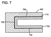
- an insert can be attached on the known wear areas of the combustor liner stop 402 as shown in Figure 7 .
- Each insert 702 can be placed either as a single substantially U-shaped piece or, for example, as three separate pieces, one per surface.
- the wear surfaces are the interior surfaces to the liner stop 402 and can be described as a first surface 704 which is substantially perpendicular to a second surface 706 which is substantially perpendicular to a third surface 708, the third surface 708 being substantially parallel to and having a substantially same surface area as the first surface 704.
- Similar inserts can be attached to the mating wear surfaces of the male mating piece 404.
- Exemplary embodiments described herein can provide an increased wear resistance to the combustion parts without the geometrical limitations associated with spray coating processes.
- inserts can have a hardness of greater than 1500 HV (Vickers pyramid number) on the various mating surfaces, which lowers the material loss due to the wear phenomena.
- the hardness is mainly driven by the presence of carbides, while the oxidation protection and the cohesion of the insert are provided by the metal matrix.
- Ductility of the inserts can be modified by changing the chemical composition of the matrix.
- hardness values for the inserts may be in a range from 1000 Vickers to 1800 Vickers, or even more in some cases.
- a fracture toughness, or ductility can range from a K IC of 5 to a K IC of 30.
- the hardness can be approximately 1250 Vickers with a K IC of approximately 20.
- a low melting point brazing alloy 710 e.g., a silver brazing powder
- a low melting point brazing alloy 710 allows penetration by the brazing alloy 710 into the insert structure, which when the brazing alloy 710 diffuses in the base material 402, creates a metallurgical joining with minimal (or no) porosity and good adhesion between the base material 402 and the inserts 702.
- these inserts can be applied to other flat or curved surfaces in a gas turbine or other device, providing that the coefficient of thermal expansion mismatch between the insert and the base material of the part to be protected is within acceptable design limits, e.g., the higher the adhesion achieved, the higher mismatch can be allowed.
- the coefficient of thermal expansion (CTE) of a base metal is about 14 °C -1 while the CTE for tungsten carbide is around 6 °C -1 , however thermal cycling tests have shown that the adhesion is maintained at 400-500 °C which is acceptable according to exemplary embodiments.
- composition inserts may be applied to a same part, e.g. the H-shaped block, with corresponding different brazing materials.
- a first insert material and a first brazing material may be used on the H-shaped block and second insert material, different from the first insert material, and a second brazing material, different from the first brazing material, may be used on a combustor liner stop.
- Exemplary inserts not according to the invention can be formed with the brazing powder mixed into the tungsten carbide powder.
- This combined powder is then exposed to pressure for compaction creating a tape-like substance, i.e., the combined powder is flexible yet has enough integrity to stick together while being applied to a wear surface.
- This tape-like substance is then applied to the desired wear surface and heat treated.
- the brazing powder in the combined powder diffuses into the base metal to fuse the tape-like substance to the base metal.
- the tungsten carbide powder is sintered.
- the step of brazing and the step of sintering are performed simultaneously.
- a polymer may be added to the mixed brazing powder and tungsten carbide powder, in low concentrations, to increase the flexibility of the tape-like substance. Additionally, the volatile organic compounds in the low concentration polymer generally burns off during the heat treating process.
- a method for reducing wear in a combustion system of a gas turbine includes: a step 902 of providing an insert that includes tungsten carbide in a metal matrix, where the metal matrix is selected from a group including cobalt and nickel; a step 904 of covering at least one known wear area of at least one substantially H-shaped block with the insert, where the at least one known wear area of the at least one substantially H-shaped block is located on an interior surface of the at least one substantially H-shaped block which includes a first surface substantially perpendicular to a second surface which is substantially perpendicular to a third surface, the third surface being substantially parallel to and having a substantially same surface area as the first surface; and a step 906 of brazing the insert to the substantially H-shaped block.
- tungsten carbide in a metal matrix e.g., cobalt or nickel
- metal matrix e.g., cobalt or nickel
- various shapes, sizes and thicknesses of pieces can be created during the sintering process as desired.
Landscapes
- Engineering & Computer Science (AREA)
- Mechanical Engineering (AREA)
- General Engineering & Computer Science (AREA)
- Chemical & Material Sciences (AREA)
- Combustion & Propulsion (AREA)
- Wood Science & Technology (AREA)
- Life Sciences & Earth Sciences (AREA)
- Powder Metallurgy (AREA)
- Turbine Rotor Nozzle Sealing (AREA)
- Carbon And Carbon Compounds (AREA)
- Ceramic Products (AREA)
- Structures Of Non-Positive Displacement Pumps (AREA)
- Coating By Spraying Or Casting (AREA)
Description
- The embodiments of the subject matter disclosed herein generally relate to wear protection and more particularly to adding inserts to combustion hardware in gas turbine systems.
- Combustors are used in a gas turbine to deliver hot combustion gases to a first stage of a turbine. Each combustor used in the system typically includes a fuel injection system with one or more fuel nozzles and a combustion chamber. A typical combustion chamber may include a combustor liner, a transition piece which is connected to and extends between the combustion chamber and the first stage of the turbine, and a flow sleeve. A passage is created between the combustor liner and the flow sleeve which allows at least a portion of the compressor discharge air to be introduced into the combustor liner for mixing with the fuel injected into the system through the fuel nozzles and for cooling purposes. Additionally, the transition piece directs and delivers the hot combustion gases to the first stage of the turbine for power generation and expansion.
- More specifically, a combustor and its associated transition piece are described with respect to
Figure 1 . Acombustor 2 for use in a gas turbine has a combustion chamber 4, which is inside of acombustion liner 6 which may be cylindrical in shape. Fuel enters the combustor chamber 4 via a nozzle(s) 12. Thecombustor liner 6 is surrounded by a substantiallycylindrical flow sleeve 8. However, a radial gap exists between thecombustor liner 6 and thecylindrical flow sleeve 8 which acts as an air flow passage to introduce air into the combustion chamber 4 to be mixed with the fuel delivered through thefuel nozzle 12. Atransition piece 10 connects thecombustor liner 6 with a first stage of a turbine (not shown). More information regarding a combustor for use in a gas turbine can be found inU.S. Patent Number 5,749,218 , entitled "Wear Reduction Kit for Gas Turbine Combustors". - The document
US 5 273 249 A shows a tungsten carbide wear reduction coating without a matrix material in a gas turbine. Thedocument FR 2 924 465 A1 EP 1 754 860 A2 shows a tungsten carbide in matrix material coating not brazed to a support structure, but applied to it via typical surface deposition methods. - During operation, some combustion parts are affected by wear induced by, for example, hardware vibrations. This wear generates maintenance and expense costs related to downtime and replacement parts. One method for reducing wear of combustion parts in a gas turbine is spray coating. For example, high velocity oxygen fuel (HVOF) coatings have been used to improve the wear characteristics on parts which have been found to have wear damage. These spray coatings, while improving wear characteristics, are not able to provide, or cost effectively provide, a thick coating and instead are typically used in applications of coatings of approximately 0.5 mm or less in thickness. Additionally, these spray coating mechanisms are performed at approximately a 90° angle to the desired coating surface. Some part geometries that it is desirable to coat, e.g., corners and various curves, do not allow for the required inclination (between the coating spray nozzle and the part surface) to be achieved which results in either a thin coating or possibly no coating at all.
- Accordingly, systems and methods for reducing wear and increasing the lifetime of parts associated with the gas turbine combustor and reducing costs are desirable.
- The present invention provides a system and method as defined in the accompanying claims.
- The accompanying drawings illustrate exemplary embodiments, wherein:
-
Figure 1 depicts a traditional combustor and a transition piece; -
Figure 2 illustrates an H-block attached to a flange according to exemplary embodiments; -
Figure 3 shows a support piece and fingers according to exemplary embodiments; -
Figure 4 illustrates a combustor liner and a combustor liner stop according to exemplary embodiments; -
Figure 5 shows a combustor liner stop and its mating piece according to exemplary embodiments; -
Figure 6 shows an H-block with inserts according to an exemplary embodiment; -
Figure 7 illustrates a combustor liner stop with an insert according to exemplary embodiments; -
Figure 8 shows an H-block with a tape-like substance covering a wear area according to exemplary embodiments; and -
Figure 9 is a flowchart illustrating a method for reducing wear according to exemplary embodiments. - The following detailed description of the exemplary embodiments refers to the accompanying drawings. The same reference numbers in different drawings identify the same or similar elements. Additionally, the drawings are not necessarily drawn to scale. Also, the following detailed description does not limit the invention. Instead, the scope of the invention is defined by the appended claims.
- Reference throughout the specification to "one embodiment" or "an embodiment" means that a particular feature, structure, or characteristic described in connection with an embodiment is included in at least one embodiment of the subject matter disclosed. Thus, the appearance of the phrases "in one embodiment" or "in an embodiment" in various places throughout the specification is not necessarily referring to the same embodiment. Further, the particular features, structures or characteristics may be combined in any suitable manner in one or more embodiments.
- As previously described, various parts of the combustor can experience wear over time caused by, for example, vibration, when the gas turbine is in use. Examples of wear locations include, but are not limited to, various connectors, connection points and stops (see
Figure 1 ) associated with the components of thecombustor liner 6 and thetransition piece 10, which are used in attaching the two components, as well as the mating points between thecombustor liner 6 and theflow sleeve 8. More specifically, stops can be used to position, secure and ensure the desired radial spacing between thecombustor liner 6 and theflow sleeve 8 at one end of thecombustor liner 6. An H-block connected to fingers is used at the other end of thecombustor liner 6 to connect thecombustor liner 6 with thetransition piece 10. The H-block is also referred to herein as a "substantially H-shaped block" and an "H-shaped block". Additionally, methods and systems for connecting these parts are generally known in the art, see, e.g.,U.S. Patent Number 5,749,218 , and as such only an overview of the connection points is described to present context for the exemplary embodiments described herein. - According to exemplary embodiments, the wear characteristics of these contact points can be modified such that their useful lifetime is extended. Prior to discussing these exemplary embodiments,
Figures 2-5 will be described to provide context with respect to the components which tend to wear in a gas turbine combustion system. Initially, as seen inFigure 2 , thetransition piece 10 can have a flangedsection 208 which has anopening 210. Within theopening 210 and attached to theflanged section 208 is an H-shaped block 202. The H-shaped block 202 can be attached to theflanged section 208 in various ways, such as, welding. WhileFigure 2 shows only a single H-shaped block 202 and a singleflanged section 208, there may be two of these pieces/sections attached to thetransition piece 10.Fingers shaped block 202 such that the opposed facing surfaces of the finger elements can engage opposite sides of thecross piece 212 of the H-shaped block 202. As shown inFigure 3 ,fingers structural member 214 which is attached to a casing (not shown) which holds thecombustor liner 6. Wear can occur on the interior surfaces of the H-shaped block 202 where thefingers fingers -
Figure 4 shows thecombustor liner 6 with an attachedcombustor liner stop 402. Numerous combustor liner stops 402 can be attached to thecombustor liner 6 to position the combustor liner as desired.Figure 5 shows thecombustor liner stop 402 and amale mating piece 404. The male mating piece is attached to the inside of theflow sleeve 8. Where these two pieces mate are also locations where wear can occur during operation of thecombustor 2. Additionally, the H-shapedblocks 202, the combustor liner stops 402 and their respective mating pieces can be made from a Cobalt based super alloy, e.g., L-605 or Hynes 25. - When in operation some of the various wear components in a
combustor 2 can have a relatively short life time which results in a higher than desired frequency of inspection and replacement. According to exemplary embodiments, the application of tungsten carbide in a metal matrix, e.g., cobalt or nickel, can increase the wear resistance of the various wear components, thus reducing the frequency of inspection and replacement of various wear components in agas turbine combustor 2. - The tungsten carbide in a metal matrix is formed into a desired shape for increasing the usable life of the part by, for example, creating a wear surface with a high hardness. For example, appropriate amounts of tungsten carbide in either cobalt or nickel still allow the part to have the desired strength and other material properties while operating at the high temperatures of the combustor. The tungsten carbide in the metal matrix, which is also referred to as a "tungsten carbide insert" or "insert" herein, may be formed through a sintering process. The tungsten carbide inserts start as tungsten carbide powders embedded in the metal matrix. The powder is placed into a die, for shaping the insert as desired. A pressure, e.g., 1000 bar, is applied to the powder and then, while in the die, the pressurized powder undergoes sintering in a furnace at approximately 1200° C. After sintering, the insert can be further modified to achieve the desired shape if needed through various processes, e.g., grinding for shape, size and surface finish. The insert may be then attached to the desired location on the part, e.g., the wear surfaces, through a brazing process using an appropriate brazing material, e.g., a low melting point brazing alloy such as a silver brazing powder, for the tungsten carbide insert and the part. According to other exemplary embodiments, the insert may be mechanically joined to the base piece, e.g., the insert can be bolted to the part.
- According to exemplary embodiments, a range of tungsten carbide in the metal matrix can be approximately between 10-20 percent by weight. Considerations for the amount of tungsten carbide to be used in the metal matrix include, but are not limited to, brittleness, ductility and hardness. Additionally, in another exemplary embodiment, the amount of tungsten carbide in the metal matrix is approximately 12 percent by weight.
- A die can be used to shape the insert or multiple dies may be used to shape multiple, possibly different, inserts. These inserts can be a single piece or a combination of pieces as desired. Additionally, sintering the tungsten carbide in a metal matrix allows the creation of inserts which are relatively thick, e.g., 1 mm or thicker, as compared to the thickness of the spray coatings, e.g., less than 1 mm but typically less than 0.5 mm, which have been traditionally used. According to another exemplary embodiment, the thickness of the inserts are in a range of 2-4 mm. Also, inserts of various shapes and geometries can be created to cover surfaces in a uniform thickness of the insert, e.g., interior corners of the H-shaped
block 202. The H-shapedblock 202 is often of the size having a length of about 5.08 cm and a width of about 2.54 cm. - According to an exemplary embodiment, an insert can be attached on the known wear areas of the H-shaped
block 202 as shown inFigure 6 . The wear surfaces associated with the H-shapedblock 202 are theinterfaces 604 between the H-shapedblock 202 and the insert(s) 602. This wear is caused by the contact and movement between the H-shapedblock 202 and thefingers 204, 206 (shown inFigures 2 and3 ). Eachinsert 602 can be placed either as a single roughly U-shaped piece or, for example, as three separate pieces, one per surface. The wear surfaces are the interior surfaces to the H-shapedblock 202 and can be described as afirst surface 606 substantially perpendicular to asecond surface 608 which is substantially perpendicular to athird surface 610, thethird surface 610 being substantially parallel to and having a substantially same surface area as thefirst surface 606. Similar inserts can be placed on the wear surfaces of thefingers - According to another exemplary embodiment, an insert can be attached on the known wear areas of the combustor liner stop 402 as shown in
Figure 7 . Eachinsert 702 can be placed either as a single substantially U-shaped piece or, for example, as three separate pieces, one per surface. The wear surfaces are the interior surfaces to theliner stop 402 and can be described as afirst surface 704 which is substantially perpendicular to asecond surface 706 which is substantially perpendicular to athird surface 708, thethird surface 708 being substantially parallel to and having a substantially same surface area as thefirst surface 704. Similar inserts can be attached to the mating wear surfaces of themale mating piece 404. - Exemplary embodiments described herein can provide an increased wear resistance to the combustion parts without the geometrical limitations associated with spray coating processes. Using sintered carbide, inserts can have a hardness of greater than 1500 HV (Vickers pyramid number) on the various mating surfaces, which lowers the material loss due to the wear phenomena. Regarding various material properties of the inserts, the hardness is mainly driven by the presence of carbides, while the oxidation protection and the cohesion of the insert are provided by the metal matrix. Ductility of the inserts can be modified by changing the chemical composition of the matrix. According to exemplary embodiments, hardness values for the inserts may be in a range from 1000 Vickers to 1800 Vickers, or even more in some cases. A fracture toughness, or ductility, can range from a KIC of 5 to a KIC of 30. According to another exemplary embodiment, the hardness can be approximately 1250 Vickers with a KIC of approximately 20.
- Using a low melting
point brazing alloy 710, e.g., a silver brazing powder, allows penetration by thebrazing alloy 710 into the insert structure, which when thebrazing alloy 710 diffuses in thebase material 402, creates a metallurgical joining with minimal (or no) porosity and good adhesion between thebase material 402 and theinserts 702. Additionally, according to exemplary embodiments, these inserts can be applied to other flat or curved surfaces in a gas turbine or other device, providing that the coefficient of thermal expansion mismatch between the insert and the base material of the part to be protected is within acceptable design limits, e.g., the higher the adhesion achieved, the higher mismatch can be allowed. For example, the coefficient of thermal expansion (CTE) of a base metal is about 14 °C-1 while the CTE for tungsten carbide is around 6 °C-1, however thermal cycling tests have shown that the adhesion is maintained at 400-500 °C which is acceptable according to exemplary embodiments. - According to exemplary embodiments, in one application, different composition inserts may be applied to a same part, e.g. the H-shaped block, with corresponding different brazing materials. In another application, a first insert material and a first brazing material may be used on the H-shaped block and second insert material, different from the first insert material, and a second brazing material, different from the first brazing material, may be used on a combustor liner stop.
- Exemplary inserts not according to the invention can be formed with the brazing powder mixed into the tungsten carbide powder. This combined powder is then exposed to pressure for compaction creating a tape-like substance, i.e., the combined powder is flexible yet has enough integrity to stick together while being applied to a wear surface. This tape-like substance is then applied to the desired wear surface and heat treated. During heat treat, the brazing powder in the combined powder diffuses into the base metal to fuse the tape-like substance to the base metal. At the same time, the tungsten carbide powder is sintered. Thus, according to this exemplary embodiment, the step of brazing and the step of sintering are performed simultaneously. An example of the tape-
like substance 802 covering awear section 804 of an H-shapedblock 202 is shown inFigure 8 . According to an alternative exemplary embodiment, a polymer may be added to the mixed brazing powder and tungsten carbide powder, in low concentrations, to increase the flexibility of the tape-like substance. Additionally, the volatile organic compounds in the low concentration polymer generally burns off during the heat treating process. - Utilizing the above-described exemplary systems according to exemplary embodiments, a method for reducing wear is shown in the flowchart of
Figure 9 . A method for reducing wear in a combustion system of a gas turbine includes: astep 902 of providing an insert that includes tungsten carbide in a metal matrix, where the metal matrix is selected from a group including cobalt and nickel; astep 904 of covering at least one known wear area of at least one substantially H-shaped block with the insert, where the at least one known wear area of the at least one substantially H-shaped block is located on an interior surface of the at least one substantially H-shaped block which includes a first surface substantially perpendicular to a second surface which is substantially perpendicular to a third surface, the third surface being substantially parallel to and having a substantially same surface area as the first surface; and astep 906 of brazing the insert to the substantially H-shaped block. - While using tungsten carbide for improved wear performance associated with parts of a gas turbine has been described in some of the exemplary embodiments described above, tungsten carbide in a metal matrix, e.g., cobalt or nickel, can be used for its properties in other applications. For example, using the tungsten carbide in a metal matrix, various shapes, sizes and thicknesses of pieces can be created during the sintering process as desired.
- The above-described exemplary embodiments are intended to be illustrative in all respects, rather than restrictive, of the present invention. Thus the present invention is capable of many variations in detailed implementation that can be derived from the description contained herein by a person skilled in the art within the scope of the present invention as defined by the appended claims.
- Also, as used herein, the article "a" is intended to include one or more items.
- This written description uses examples of the subject matter disclosed to enable any person skilled in the art to practice the same, including making and using any devices or systems and performing any incorporated methods.
Claims (9)
- A system for wear reduction in a combustion system of a gas turbine, said system comprising:at least one substantially H-shaped block (202) configured to secure a transition piece (10) of a gas turbine combustor to a support piece (214);a first insert (602,702) including a first tungsten carbide in a first metal matrix, wherein said first metal matrix is selected from a group comprising cobalt and nickel; anda first brazing material (710) between said at least one substantially H-shaped block (202) and said first insert (602,702) said first brazing material being configured to braze said first insert (602, 702) to said at least one substantially H-shaped block (202) in at least one location on an interior wear surface of said at least one substantially H-shaped block (202),wherein said interior surface of said at least one substantially H-shaped block (202) includes a first surface (606) substantially perpendicular to a second surface (608) which is substantially perpendicular to a third surface (610), said third surface (610) being substantially parallel to and having a substantially same surface area as said first surface (606).
- The system of claim 1, further comprising:at least one combustor liner stop (402) configured to attach to a combustors liner (6) of the gas turbine;a second insert including a second tungsten carbide in a second metal matrix, wherein said second metal matrix is selected from a group comprising cobalt and nickel; anda second brazing material between said at least one combustor liner (6) stop and said second insert, said second brazing material being configured to braze said second insert to said at least one combustor liner stop (402) in at least one location on an substantially U-shaped wear surface of said at least one combustor liner stop (402).
- The system of claim 1 or claim 2, wherein a composition of said first or second or both tungsten carbides in said first or second or both metal matrices is in the range of 10 to 20 percent by weight.
- The system of any preceding claim, wherein said first insert has a thickness greater than or equal to 1.0 mm.
- The system of claim 1, wherein the insert includes either a cobalt matrix with tungsten carbide or a nickel matrix with tungsten carbide wherein said tungsten carbide comprises between 10 and 20 percent by weight of said insert.
- A method for reducing wear in a combustion system of a gas turbine, said method comprising:providing (902) an insert that includes tungsten carbide in a metal matrix, wherein said metal matrix is selected from a group comprising cobalt and nickel;covering (904) at least one known wear area of at least one substantially H-shaped block (202) with said insert, wherein said at least one known wear area of said at least one substantially H-shaped block (202) is located on an interior surface of said at least one substantially H-shaped block (202) and includes a first surface (606) substantially perpendicular to a second surface (608) which is substantially perpendicular to a third surface (610), said third surface (610) being substantially parallel to and having a substantially same surface area as said first surface (606); andbrazing (906) said insert to said substantially H-shaped block (202).
- The method of claim 6, wherein a composition of said tungsten carbide in said metal matrix is in the range of 10 to 20 percent by weight.
- The method of claim 6 or claim 7, further comprising:covering at least one known wear area of a combustor liner stop (402) with an insert (702); andbrazing said insert to said combustor liner stop (402).
- The method of any of claims 6 to 8, further comprising:forming said tungsten carbide in said metal matrix into said insert through a sintering process in a die.
Applications Claiming Priority (2)
| Application Number | Priority Date | Filing Date | Title |
|---|---|---|---|
| ITCO2009A000065A IT1396884B1 (en) | 2009-12-15 | 2009-12-15 | INSERTS IN TUNGSTEN CARBIDE AND METHOD |
| PCT/EP2010/069239 WO2011073075A2 (en) | 2009-12-15 | 2010-12-09 | Tungsten carbide inserts and method |
Publications (2)
| Publication Number | Publication Date |
|---|---|
| EP2513563A2 EP2513563A2 (en) | 2012-10-24 |
| EP2513563B1 true EP2513563B1 (en) | 2016-08-10 |
Family
ID=42340695
Family Applications (1)
| Application Number | Title | Priority Date | Filing Date |
|---|---|---|---|
| EP10787777.1A Not-in-force EP2513563B1 (en) | 2009-12-15 | 2010-12-09 | Tungsten carbide inserts for a gas turbine liner and method |
Country Status (10)
| Country | Link |
|---|---|
| US (1) | US20130199193A1 (en) |
| EP (1) | EP2513563B1 (en) |
| KR (1) | KR20120092711A (en) |
| CN (1) | CN102741615B (en) |
| AU (1) | AU2010333066B2 (en) |
| BR (1) | BR112012015862B8 (en) |
| CA (1) | CA2784957A1 (en) |
| IT (1) | IT1396884B1 (en) |
| RU (1) | RU2549755C2 (en) |
| WO (1) | WO2011073075A2 (en) |
Families Citing this family (4)
| Publication number | Priority date | Publication date | Assignee | Title |
|---|---|---|---|---|
| US20150068212A1 (en) * | 2012-04-19 | 2015-03-12 | General Electric Company | Combustor liner stop |
| CA2924550C (en) | 2013-10-17 | 2019-02-12 | Halliburton Energy Services, Inc. | Particulate reinforced braze alloys for drill bits |
| US10571126B2 (en) * | 2017-02-08 | 2020-02-25 | General Electric Company | Method to provide a braze coating with wear property on micromixer tubes |
| CA3086041A1 (en) * | 2017-12-19 | 2019-06-27 | Stephen Henry Marshall | Composite metal component and method of producing same |
Family Cites Families (30)
| Publication number | Priority date | Publication date | Assignee | Title |
|---|---|---|---|---|
| US3512962A (en) * | 1966-01-03 | 1970-05-19 | Iit Res Inst | Cobalt-tungsten carbide alloy and process |
| SE329799B (en) * | 1969-02-07 | 1970-10-19 | Nordstjernan Rederi Ab | |
| US3743556A (en) * | 1970-03-30 | 1973-07-03 | Composite Sciences | Coating metallic substrate with powdered filler and molten metal |
| SU423594A1 (en) * | 1972-09-06 | 1974-04-15 | В. Н. Ткачев , А. В. Ваган | CHARGE FOR INDUCTION SURFACE |
| US4257741A (en) * | 1978-11-02 | 1981-03-24 | General Electric Company | Turbine engine blade with airfoil projection |
| US4330333A (en) * | 1980-08-29 | 1982-05-18 | The Valeron Corporation | High titanium nitride cutting material |
| US4802679A (en) * | 1987-12-31 | 1989-02-07 | Westinghouse Electric Corp. | Bell seal of improved stability for high pressure turbines |
| US5352526A (en) * | 1990-02-06 | 1994-10-04 | Pullman Company | Hardfaced article and process to prevent crack propagation in hardfaced substrates |
| US5182080A (en) * | 1990-12-27 | 1993-01-26 | General Electric Company | Advanced high-temperature brazing alloys |
| US5273249A (en) * | 1992-11-12 | 1993-12-28 | General Electric Company | Slide joint bracket |
| US5749218A (en) * | 1993-12-17 | 1998-05-12 | General Electric Co. | Wear reduction kit for gas turbine combustors |
| US6478887B1 (en) * | 1998-12-16 | 2002-11-12 | Smith International, Inc. | Boronized wear-resistant materials and methods thereof |
| US6649682B1 (en) * | 1998-12-22 | 2003-11-18 | Conforma Clad, Inc | Process for making wear-resistant coatings |
| US20040124231A1 (en) * | 1999-06-29 | 2004-07-01 | Hasz Wayne Charles | Method for coating a substrate |
| US6497758B1 (en) * | 2000-07-12 | 2002-12-24 | General Electric Company | Method for applying a high-temperature bond coat on a metal substrate, and related compositions and articles |
| US6904756B2 (en) * | 2003-02-28 | 2005-06-14 | Power Systems Mfg, Llc | Transition duct support bracket wear cover |
| US7207770B2 (en) * | 2003-05-27 | 2007-04-24 | General Electric Company | Variable stator vane bushings and washers |
| KR100663666B1 (en) * | 2005-04-22 | 2007-01-02 | 한국야금 주식회사 | Toughness Titanium Carbonate Group Cermet and Manufacturing Method Thereof |
| EP1727371A1 (en) * | 2005-05-27 | 2006-11-29 | Thomson Licensing | Method for controlling the encoder output bit rate in a block-based video encoder, and corresponding video encoder apparatus |
| US7597159B2 (en) * | 2005-09-09 | 2009-10-06 | Baker Hughes Incorporated | Drill bits and drilling tools including abrasive wear-resistant materials |
| DE102005044991A1 (en) * | 2005-09-21 | 2007-03-22 | Mtu Aero Engines Gmbh | Process for producing a protective layer, protective layer and component with a protective layer |
| US20070099027A1 (en) * | 2005-10-28 | 2007-05-03 | Anand Krishnamurthy | Wear resistant coatings |
| US20090011276A1 (en) * | 2005-10-28 | 2009-01-08 | Kazim Ozbaysal | Silver/aluminum/copper/titanium nickel/brazing alloys for brazing wc-co to titanium and alloys thereof, brazing methods, and brazed articles |
| US7293688B2 (en) * | 2005-11-14 | 2007-11-13 | General Electric Company | Gold/nickel/copper/aluminum/silver brazing alloys for brazing WC-Co to titanium alloys |
| US7575042B2 (en) * | 2006-03-30 | 2009-08-18 | General Electric Company | Methods for the formation of refractory metal intermetallic composites, and related articles and compositions |
| US20080145649A1 (en) * | 2006-12-14 | 2008-06-19 | General Electric | Protective coatings which provide wear resistance and low friction characteristics, and related articles and methods |
| US20080166233A1 (en) * | 2007-01-09 | 2008-07-10 | General Electric Company | Turbine component with repaired seal land and related method |
| DE102007047629A1 (en) * | 2007-04-13 | 2008-10-16 | Stein, Ralf | Method of applying a high-strength coating to workpieces and / or materials |
| US7909300B2 (en) * | 2007-10-18 | 2011-03-22 | General Electric Company | Combustor bracket assembly |
| FR2924465B1 (en) * | 2007-12-03 | 2013-07-12 | Jean Sandoz | GAS TURBINE COMPRISING A WHEEL WITH RADIAL WING TYPE AUBES AND METHOD FOR MANUFACTURING THE FINS OF THE TURBINE. |
-
2009
- 2009-12-15 IT ITCO2009A000065A patent/IT1396884B1/en active
-
2010
- 2010-12-09 CA CA2784957A patent/CA2784957A1/en not_active Abandoned
- 2010-12-09 AU AU2010333066A patent/AU2010333066B2/en not_active Ceased
- 2010-12-09 KR KR1020127018356A patent/KR20120092711A/en not_active Ceased
- 2010-12-09 CN CN201080063953.2A patent/CN102741615B/en not_active Expired - Fee Related
- 2010-12-09 WO PCT/EP2010/069239 patent/WO2011073075A2/en not_active Ceased
- 2010-12-09 US US13/516,683 patent/US20130199193A1/en not_active Abandoned
- 2010-12-09 RU RU2012126744/06A patent/RU2549755C2/en not_active IP Right Cessation
- 2010-12-09 EP EP10787777.1A patent/EP2513563B1/en not_active Not-in-force
- 2010-12-09 BR BR112012015862A patent/BR112012015862B8/en not_active IP Right Cessation
Also Published As
| Publication number | Publication date |
|---|---|
| RU2012126744A (en) | 2014-01-27 |
| KR20120092711A (en) | 2012-08-21 |
| ITCO20090065A1 (en) | 2011-06-16 |
| EP2513563A2 (en) | 2012-10-24 |
| BR112012015862A2 (en) | 2016-06-21 |
| US20130199193A1 (en) | 2013-08-08 |
| CN102741615B (en) | 2014-12-17 |
| BR112012015862B8 (en) | 2020-09-01 |
| WO2011073075A3 (en) | 2011-08-25 |
| CA2784957A1 (en) | 2011-06-23 |
| AU2010333066B2 (en) | 2016-07-14 |
| RU2549755C2 (en) | 2015-04-27 |
| WO2011073075A2 (en) | 2011-06-23 |
| AU2010333066A1 (en) | 2012-07-12 |
| IT1396884B1 (en) | 2012-12-20 |
| BR112012015862B1 (en) | 2020-08-11 |
| CN102741615A (en) | 2012-10-17 |
Similar Documents
| Publication | Publication Date | Title |
|---|---|---|
| KR100802328B1 (en) | Method for forming a wear-resistant metal base composite coating layer and coating layer prepared using | |
| EP1730323B1 (en) | Cold gas-dynamic spray repair on gas turbine engine components | |
| CN102251984B (en) | Jacket impeller with functional graded material and method | |
| EP1921181A1 (en) | Cold sprayed porous metal seals | |
| US20110143039A1 (en) | Process and device for cold spraying | |
| AU2010333066B2 (en) | Tungsten carbide inserts for a gas turbine liner and method | |
| KR101171682B1 (en) | A method for Nitriding Surface of Aluminum or Aluminum Alloy by Cold Spray Method | |
| EP2312012A1 (en) | Method for producing a crack-free abradable coating with enhanced adhesion | |
| JP6216570B2 (en) | Component with cooling channel and manufacturing method | |
| JP6054137B2 (en) | High temperature member for gas turbine having thermal barrier coating | |
| Higuera et al. | Influence of the thermal-spray procedure on the properties of a CoNiCrAlY coating | |
| US10711636B2 (en) | Feedstocks for use in coating components | |
| US20040213919A1 (en) | Coating process and coated base material | |
| EP2604365B1 (en) | Anti-wear functional graded material and method | |
| JP7536419B2 (en) | Method for providing abrasion-resistant braze coating on micromixer tubes - Patents.com | |
| US12385405B2 (en) | Wear resistant article and method of making | |
| EP3276039A1 (en) | Outer airseal abradable rub strip manufacture methods and apparatus | |
| JP2018169150A5 (en) | ||
| EP4397788A1 (en) | Wear resistant article and method of making | |
| JP2004099955A (en) | Abrasion resistant coating and application method therefor |
Legal Events
| Date | Code | Title | Description |
|---|---|---|---|
| PUAI | Public reference made under article 153(3) epc to a published international application that has entered the european phase |
Free format text: ORIGINAL CODE: 0009012 |
|
| 17P | Request for examination filed |
Effective date: 20120716 |
|
| AK | Designated contracting states |
Kind code of ref document: A2 Designated state(s): AL AT BE BG CH CY CZ DE DK EE ES FI FR GB GR HR HU IE IS IT LI LT LU LV MC MK MT NL NO PL PT RO RS SE SI SK SM TR |
|
| DAX | Request for extension of the european patent (deleted) | ||
| 17Q | First examination report despatched |
Effective date: 20150218 |
|
| GRAP | Despatch of communication of intention to grant a patent |
Free format text: ORIGINAL CODE: EPIDOSNIGR1 |
|
| RIC1 | Information provided on ipc code assigned before grant |
Ipc: B32B 5/16 20060101ALI20160219BHEP Ipc: F02C 7/20 20060101ALI20160219BHEP Ipc: F23R 3/60 20060101AFI20160219BHEP Ipc: B32B 15/04 20060101ALI20160219BHEP Ipc: F01D 9/02 20060101ALI20160219BHEP |
|
| INTG | Intention to grant announced |
Effective date: 20160307 |
|
| GRAS | Grant fee paid |
Free format text: ORIGINAL CODE: EPIDOSNIGR3 |
|
| GRAA | (expected) grant |
Free format text: ORIGINAL CODE: 0009210 |
|
| AK | Designated contracting states |
Kind code of ref document: B1 Designated state(s): AL AT BE BG CH CY CZ DE DK EE ES FI FR GB GR HR HU IE IS IT LI LT LU LV MC MK MT NL NO PL PT RO RS SE SI SK SM TR |
|
| REG | Reference to a national code |
Ref country code: GB Ref legal event code: FG4D |
|
| REG | Reference to a national code |
Ref country code: AT Ref legal event code: REF Ref document number: 819398 Country of ref document: AT Kind code of ref document: T Effective date: 20160815 Ref country code: CH Ref legal event code: EP |
|
| REG | Reference to a national code |
Ref country code: IE Ref legal event code: FG4D |
|
| REG | Reference to a national code |
Ref country code: DE Ref legal event code: R096 Ref document number: 602010035422 Country of ref document: DE |
|
| REG | Reference to a national code |
Ref country code: NL Ref legal event code: FP |
|
| REG | Reference to a national code |
Ref country code: NO Ref legal event code: T2 Effective date: 20160810 |
|
| REG | Reference to a national code |
Ref country code: LT Ref legal event code: MG4D |
|
| REG | Reference to a national code |
Ref country code: FR Ref legal event code: PLFP Year of fee payment: 7 |
|
| REG | Reference to a national code |
Ref country code: AT Ref legal event code: MK05 Ref document number: 819398 Country of ref document: AT Kind code of ref document: T Effective date: 20160810 |
|
| PG25 | Lapsed in a contracting state [announced via postgrant information from national office to epo] |
Ref country code: LT Free format text: LAPSE BECAUSE OF FAILURE TO SUBMIT A TRANSLATION OF THE DESCRIPTION OR TO PAY THE FEE WITHIN THE PRESCRIBED TIME-LIMIT Effective date: 20160810 Ref country code: FI Free format text: LAPSE BECAUSE OF FAILURE TO SUBMIT A TRANSLATION OF THE DESCRIPTION OR TO PAY THE FEE WITHIN THE PRESCRIBED TIME-LIMIT Effective date: 20160810 Ref country code: RS Free format text: LAPSE BECAUSE OF FAILURE TO SUBMIT A TRANSLATION OF THE DESCRIPTION OR TO PAY THE FEE WITHIN THE PRESCRIBED TIME-LIMIT Effective date: 20160810 Ref country code: IS Free format text: LAPSE BECAUSE OF FAILURE TO SUBMIT A TRANSLATION OF THE DESCRIPTION OR TO PAY THE FEE WITHIN THE PRESCRIBED TIME-LIMIT Effective date: 20161210 Ref country code: IT Free format text: LAPSE BECAUSE OF FAILURE TO SUBMIT A TRANSLATION OF THE DESCRIPTION OR TO PAY THE FEE WITHIN THE PRESCRIBED TIME-LIMIT Effective date: 20160810 |
|
| PG25 | Lapsed in a contracting state [announced via postgrant information from national office to epo] |
Ref country code: LV Free format text: LAPSE BECAUSE OF FAILURE TO SUBMIT A TRANSLATION OF THE DESCRIPTION OR TO PAY THE FEE WITHIN THE PRESCRIBED TIME-LIMIT Effective date: 20160810 Ref country code: ES Free format text: LAPSE BECAUSE OF FAILURE TO SUBMIT A TRANSLATION OF THE DESCRIPTION OR TO PAY THE FEE WITHIN THE PRESCRIBED TIME-LIMIT Effective date: 20160810 Ref country code: PT Free format text: LAPSE BECAUSE OF FAILURE TO SUBMIT A TRANSLATION OF THE DESCRIPTION OR TO PAY THE FEE WITHIN THE PRESCRIBED TIME-LIMIT Effective date: 20161212 Ref country code: PL Free format text: LAPSE BECAUSE OF FAILURE TO SUBMIT A TRANSLATION OF THE DESCRIPTION OR TO PAY THE FEE WITHIN THE PRESCRIBED TIME-LIMIT Effective date: 20160810 Ref country code: GR Free format text: LAPSE BECAUSE OF FAILURE TO SUBMIT A TRANSLATION OF THE DESCRIPTION OR TO PAY THE FEE WITHIN THE PRESCRIBED TIME-LIMIT Effective date: 20161111 Ref country code: SE Free format text: LAPSE BECAUSE OF FAILURE TO SUBMIT A TRANSLATION OF THE DESCRIPTION OR TO PAY THE FEE WITHIN THE PRESCRIBED TIME-LIMIT Effective date: 20160810 Ref country code: AT Free format text: LAPSE BECAUSE OF FAILURE TO SUBMIT A TRANSLATION OF THE DESCRIPTION OR TO PAY THE FEE WITHIN THE PRESCRIBED TIME-LIMIT Effective date: 20160810 |
|
| PG25 | Lapsed in a contracting state [announced via postgrant information from national office to epo] |
Ref country code: RO Free format text: LAPSE BECAUSE OF FAILURE TO SUBMIT A TRANSLATION OF THE DESCRIPTION OR TO PAY THE FEE WITHIN THE PRESCRIBED TIME-LIMIT Effective date: 20160810 Ref country code: EE Free format text: LAPSE BECAUSE OF FAILURE TO SUBMIT A TRANSLATION OF THE DESCRIPTION OR TO PAY THE FEE WITHIN THE PRESCRIBED TIME-LIMIT Effective date: 20160810 |
|
| REG | Reference to a national code |
Ref country code: DE Ref legal event code: R097 Ref document number: 602010035422 Country of ref document: DE |
|
| PG25 | Lapsed in a contracting state [announced via postgrant information from national office to epo] |
Ref country code: BE Free format text: LAPSE BECAUSE OF FAILURE TO SUBMIT A TRANSLATION OF THE DESCRIPTION OR TO PAY THE FEE WITHIN THE PRESCRIBED TIME-LIMIT Effective date: 20160810 Ref country code: SK Free format text: LAPSE BECAUSE OF FAILURE TO SUBMIT A TRANSLATION OF THE DESCRIPTION OR TO PAY THE FEE WITHIN THE PRESCRIBED TIME-LIMIT Effective date: 20160810 Ref country code: BG Free format text: LAPSE BECAUSE OF FAILURE TO SUBMIT A TRANSLATION OF THE DESCRIPTION OR TO PAY THE FEE WITHIN THE PRESCRIBED TIME-LIMIT Effective date: 20161110 Ref country code: CZ Free format text: LAPSE BECAUSE OF FAILURE TO SUBMIT A TRANSLATION OF THE DESCRIPTION OR TO PAY THE FEE WITHIN THE PRESCRIBED TIME-LIMIT Effective date: 20160810 Ref country code: SM Free format text: LAPSE BECAUSE OF FAILURE TO SUBMIT A TRANSLATION OF THE DESCRIPTION OR TO PAY THE FEE WITHIN THE PRESCRIBED TIME-LIMIT Effective date: 20160810 Ref country code: DK Free format text: LAPSE BECAUSE OF FAILURE TO SUBMIT A TRANSLATION OF THE DESCRIPTION OR TO PAY THE FEE WITHIN THE PRESCRIBED TIME-LIMIT Effective date: 20160810 |
|
| PLBE | No opposition filed within time limit |
Free format text: ORIGINAL CODE: 0009261 |
|
| STAA | Information on the status of an ep patent application or granted ep patent |
Free format text: STATUS: NO OPPOSITION FILED WITHIN TIME LIMIT |
|
| 26N | No opposition filed |
Effective date: 20170511 |
|
| PG25 | Lapsed in a contracting state [announced via postgrant information from national office to epo] |
Ref country code: SI Free format text: LAPSE BECAUSE OF FAILURE TO SUBMIT A TRANSLATION OF THE DESCRIPTION OR TO PAY THE FEE WITHIN THE PRESCRIBED TIME-LIMIT Effective date: 20160810 |
|
| PG25 | Lapsed in a contracting state [announced via postgrant information from national office to epo] |
Ref country code: MC Free format text: LAPSE BECAUSE OF FAILURE TO SUBMIT A TRANSLATION OF THE DESCRIPTION OR TO PAY THE FEE WITHIN THE PRESCRIBED TIME-LIMIT Effective date: 20160810 |
|
| REG | Reference to a national code |
Ref country code: IE Ref legal event code: MM4A |
|
| PG25 | Lapsed in a contracting state [announced via postgrant information from national office to epo] |
Ref country code: LU Free format text: LAPSE BECAUSE OF NON-PAYMENT OF DUE FEES Effective date: 20161209 |
|
| PG25 | Lapsed in a contracting state [announced via postgrant information from national office to epo] |
Ref country code: IE Free format text: LAPSE BECAUSE OF NON-PAYMENT OF DUE FEES Effective date: 20161209 |
|
| REG | Reference to a national code |
Ref country code: FR Ref legal event code: PLFP Year of fee payment: 8 |
|
| PG25 | Lapsed in a contracting state [announced via postgrant information from national office to epo] |
Ref country code: HU Free format text: LAPSE BECAUSE OF FAILURE TO SUBMIT A TRANSLATION OF THE DESCRIPTION OR TO PAY THE FEE WITHIN THE PRESCRIBED TIME-LIMIT; INVALID AB INITIO Effective date: 20101209 Ref country code: CY Free format text: LAPSE BECAUSE OF FAILURE TO SUBMIT A TRANSLATION OF THE DESCRIPTION OR TO PAY THE FEE WITHIN THE PRESCRIBED TIME-LIMIT Effective date: 20160810 |
|
| PG25 | Lapsed in a contracting state [announced via postgrant information from national office to epo] |
Ref country code: MK Free format text: LAPSE BECAUSE OF FAILURE TO SUBMIT A TRANSLATION OF THE DESCRIPTION OR TO PAY THE FEE WITHIN THE PRESCRIBED TIME-LIMIT Effective date: 20160810 Ref country code: TR Free format text: LAPSE BECAUSE OF FAILURE TO SUBMIT A TRANSLATION OF THE DESCRIPTION OR TO PAY THE FEE WITHIN THE PRESCRIBED TIME-LIMIT Effective date: 20160810 Ref country code: HR Free format text: LAPSE BECAUSE OF FAILURE TO SUBMIT A TRANSLATION OF THE DESCRIPTION OR TO PAY THE FEE WITHIN THE PRESCRIBED TIME-LIMIT Effective date: 20160810 |
|
| PG25 | Lapsed in a contracting state [announced via postgrant information from national office to epo] |
Ref country code: MT Free format text: LAPSE BECAUSE OF NON-PAYMENT OF DUE FEES Effective date: 20161209 |
|
| PG25 | Lapsed in a contracting state [announced via postgrant information from national office to epo] |
Ref country code: AL Free format text: LAPSE BECAUSE OF FAILURE TO SUBMIT A TRANSLATION OF THE DESCRIPTION OR TO PAY THE FEE WITHIN THE PRESCRIBED TIME-LIMIT Effective date: 20160810 |
|
| PGFP | Annual fee paid to national office [announced via postgrant information from national office to epo] |
Ref country code: NL Payment date: 20191125 Year of fee payment: 10 Ref country code: NO Payment date: 20191125 Year of fee payment: 10 |
|
| PGFP | Annual fee paid to national office [announced via postgrant information from national office to epo] |
Ref country code: CH Payment date: 20191121 Year of fee payment: 10 |
|
| PGFP | Annual fee paid to national office [announced via postgrant information from national office to epo] |
Ref country code: GB Payment date: 20191122 Year of fee payment: 10 |
|
| REG | Reference to a national code |
Ref country code: NO Ref legal event code: MMEP |
|
| REG | Reference to a national code |
Ref country code: CH Ref legal event code: PL |
|
| REG | Reference to a national code |
Ref country code: NL Ref legal event code: MM Effective date: 20210101 |
|
| GBPC | Gb: european patent ceased through non-payment of renewal fee |
Effective date: 20201209 |
|
| PG25 | Lapsed in a contracting state [announced via postgrant information from national office to epo] |
Ref country code: NL Free format text: LAPSE BECAUSE OF NON-PAYMENT OF DUE FEES Effective date: 20210101 |
|
| PG25 | Lapsed in a contracting state [announced via postgrant information from national office to epo] |
Ref country code: LI Free format text: LAPSE BECAUSE OF NON-PAYMENT OF DUE FEES Effective date: 20201231 Ref country code: NO Free format text: LAPSE BECAUSE OF NON-PAYMENT OF DUE FEES Effective date: 20201231 Ref country code: CH Free format text: LAPSE BECAUSE OF NON-PAYMENT OF DUE FEES Effective date: 20201231 Ref country code: GB Free format text: LAPSE BECAUSE OF NON-PAYMENT OF DUE FEES Effective date: 20201209 |
|
| PGFP | Annual fee paid to national office [announced via postgrant information from national office to epo] |
Ref country code: DE Payment date: 20211117 Year of fee payment: 12 Ref country code: FR Payment date: 20211117 Year of fee payment: 12 |
|
| REG | Reference to a national code |
Ref country code: DE Ref legal event code: R119 Ref document number: 602010035422 Country of ref document: DE |
|
| PG25 | Lapsed in a contracting state [announced via postgrant information from national office to epo] |
Ref country code: DE Free format text: LAPSE BECAUSE OF NON-PAYMENT OF DUE FEES Effective date: 20230701 |
|
| PG25 | Lapsed in a contracting state [announced via postgrant information from national office to epo] |
Ref country code: FR Free format text: LAPSE BECAUSE OF NON-PAYMENT OF DUE FEES Effective date: 20221231 |