EP2513472B1 - Rotorelement für ein energieerzeugungssystem und energieerzeugungssystem dafür - Google Patents
Rotorelement für ein energieerzeugungssystem und energieerzeugungssystem dafür Download PDFInfo
- Publication number
- EP2513472B1 EP2513472B1 EP10807609.2A EP10807609A EP2513472B1 EP 2513472 B1 EP2513472 B1 EP 2513472B1 EP 10807609 A EP10807609 A EP 10807609A EP 2513472 B1 EP2513472 B1 EP 2513472B1
- Authority
- EP
- European Patent Office
- Prior art keywords
- axis
- fin
- blades
- rotor
- rotor element
- Prior art date
- Legal status (The legal status is an assumption and is not a legal conclusion. Google has not performed a legal analysis and makes no representation as to the accuracy of the status listed.)
- Not-in-force
Links
- 238000010248 power generation Methods 0.000 title description 5
- 239000012530 fluid Substances 0.000 description 16
- 241000940835 Pales Species 0.000 description 5
- 206010033546 Pallor Diseases 0.000 description 5
- 238000004519 manufacturing process Methods 0.000 description 4
- 230000000135 prohibitive effect Effects 0.000 description 2
- 238000003466 welding Methods 0.000 description 2
- 241001080024 Telles Species 0.000 description 1
- 230000000694 effects Effects 0.000 description 1
- 230000005611 electricity Effects 0.000 description 1
- 238000009434 installation Methods 0.000 description 1
- 230000003014 reinforcing effect Effects 0.000 description 1
- 238000009827 uniform distribution Methods 0.000 description 1
- XLYOFNOQVPJJNP-UHFFFAOYSA-N water Substances O XLYOFNOQVPJJNP-UHFFFAOYSA-N 0.000 description 1
Images

Classifications
-
- F—MECHANICAL ENGINEERING; LIGHTING; HEATING; WEAPONS; BLASTING
- F03—MACHINES OR ENGINES FOR LIQUIDS; WIND, SPRING, OR WEIGHT MOTORS; PRODUCING MECHANICAL POWER OR A REACTIVE PROPULSIVE THRUST, NOT OTHERWISE PROVIDED FOR
- F03D—WIND MOTORS
- F03D3/00—Wind motors with rotation axis substantially perpendicular to the air flow entering the rotor
- F03D3/06—Rotors
- F03D3/062—Rotors characterised by their construction elements
- F03D3/066—Rotors characterised by their construction elements the wind engaging parts being movable relative to the rotor
- F03D3/067—Cyclic movements
-
- F—MECHANICAL ENGINEERING; LIGHTING; HEATING; WEAPONS; BLASTING
- F03—MACHINES OR ENGINES FOR LIQUIDS; WIND, SPRING, OR WEIGHT MOTORS; PRODUCING MECHANICAL POWER OR A REACTIVE PROPULSIVE THRUST, NOT OTHERWISE PROVIDED FOR
- F03D—WIND MOTORS
- F03D3/00—Wind motors with rotation axis substantially perpendicular to the air flow entering the rotor
- F03D3/06—Rotors
- F03D3/061—Rotors characterised by their aerodynamic shape, e.g. aerofoil profiles
-
- F—MECHANICAL ENGINEERING; LIGHTING; HEATING; WEAPONS; BLASTING
- F05—INDEXING SCHEMES RELATING TO ENGINES OR PUMPS IN VARIOUS SUBCLASSES OF CLASSES F01-F04
- F05B—INDEXING SCHEME RELATING TO WIND, SPRING, WEIGHT, INERTIA OR LIKE MOTORS, TO MACHINES OR ENGINES FOR LIQUIDS COVERED BY SUBCLASSES F03B, F03D AND F03G
- F05B2210/00—Working fluid
- F05B2210/16—Air or water being indistinctly used as working fluid, i.e. the machine can work equally with air or water without any modification
-
- Y—GENERAL TAGGING OF NEW TECHNOLOGICAL DEVELOPMENTS; GENERAL TAGGING OF CROSS-SECTIONAL TECHNOLOGIES SPANNING OVER SEVERAL SECTIONS OF THE IPC; TECHNICAL SUBJECTS COVERED BY FORMER USPC CROSS-REFERENCE ART COLLECTIONS [XRACs] AND DIGESTS
- Y02—TECHNOLOGIES OR APPLICATIONS FOR MITIGATION OR ADAPTATION AGAINST CLIMATE CHANGE
- Y02E—REDUCTION OF GREENHOUSE GAS [GHG] EMISSIONS, RELATED TO ENERGY GENERATION, TRANSMISSION OR DISTRIBUTION
- Y02E10/00—Energy generation through renewable energy sources
- Y02E10/70—Wind energy
- Y02E10/74—Wind turbines with rotation axis perpendicular to the wind direction
Definitions
- the present invention relates to a rotor element for a power generation system and a power generation system using it.
- the rotor, and therefore the wind turbine must be large enough to capture enough energy.
- the rotors are of complex shapes and difficult to manufacture and maintain.
- This rotor element can thus be used in miniature wind turbines, which can be implemented at home, in gardens or balconies, to produce electricity.
- Patent application is known FR2442979 a wind turbine having a rotor element with blades juxtaposed on the rotor axis.
- FR2442979 the blade shape of the rotor element does not allow optimum use of the incident fluid flow.
- a rotor element with blades juxtaposed on the rotor axis consist of two fins shaped half-cylinder.
- the rotor element disclosed in GB2412948 does not allow optimal use of the incident fluid flow.
- the present invention aims to solve the problems of the prior art, and proposes a rotor element, in particular adapted to be installed on a wind turbine as a rotor, or in any device for producing energy using a flow of fluid to drive a rotating axis to produce energy.
- the angle formed by the second surface and the third surface is preferably of the order of 120 °.
- This structure of the fins of each blade makes it possible to obtain a jerky movement of the rotor when it is driven by a flow of fluid on the blades, the jerky movement making it possible to trigger the rotation drive of the wind turbine, even with a slight flow of fluid incident on the wind turbine.
- the symmetry with respect to the axis is the three-dimensional symmetry operation which, at each point of a fin, associates a symmetric point with respect to the axis in a plane containing the axis and the point of the fin considered, so that in the plane considered, the axis is the mediator of the segment formed by the point of the fin and considered its symmetrical.
- the fins of the same blade are therefore in opposite and opposite position with respect to the axis, the effect being that, for the same blade, the resistance of the opposite blade at the vane that gathers the movement is minimal.
- the contiguous nature of the blades on the axis makes it possible to maximize a contact surface with the fluid in flow on the rotor element. This also allows a flow of fluid between the different blades, since no element separates the different blades on the axis.
- the fluid may be air or water, for example.
- the angle formed between the mean planes of two consecutive blades on the axis of the rotor element and containing the axis of the rotor element is equal at 360 ° divided by the number of blades on the axis of the rotor element.
- the first, second and third surfaces of each fin are rectangular.
- each fin may have a common dimension in the direction of the axis of the rotor element.
- the dimension in the direction of the axis of the rotor element of each fin increases continuously from the end of the fin connected to the axis of the rotor element to the free end of the fin.
- each fin surface consists of two orthogonal facets to one another, the common edges of the facets of the first surface, facets of the second surface and facets of the third surface belonging to each other. at the same plane orthogonal to the axis.
- each fin of the third variant of the blade allows a better grip in the wind of the fin facing the incident fluid flow, the fin facing the incident fluid flow being defined as being the fin whose second surface is in the direction of the fluid incident flow, extending from the first surface in the direction contrary to the incident fluid flow.
- the angle between two surfaces of the blade is calculated as the angle between the plane forming an angle of 45 ° with each facet of a surface and the plane forming an angle of 45 ° with each facet of the other surface.
- the average plane of the blade for this third variant is then the plane containing the rotor axis and the plane forming an angle of 45 ° with each facet of the first two surfaces of the blade.
- Each fin may comprise an angled return on the edges of the first, second and third non-axis parallel surfaces, said angled return being directed towards the fin side in which the first and second surfaces form a 90 ° angle. .
- the invention also relates to a vertical axis wind turbine, characterized in that a rotor element as defined above constitutes the rotor of the wind turbine.
- the invention also relates to a vertical axis wind turbine comprising a vertical axis connected to a lower end to a dynamo, and comprising at its upper end one or more branches, each constituted by a rotor element as defined above. .
- the rotor element as defined above can also be implemented on other devices of energy production as wind turbines, using the flow of a fluid other than the wind.
- the rotor element as defined above could for example be used to produce energy by rotating the axis following a flow of fluid on the rotor.
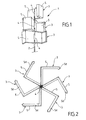
- the rotor element 1 comprises an axis 2 and a plurality of blades 3, juxtaposed to each other on the axis 2.
- Each blade 3 comprises a fastening element 4 on the axis 2 of the rotor element 1, and two fins 5, fixed, for example by welding, on the fastening element 4.
- Each fin 5 consists of three rectangular surfaces, 5a, 5b, 5c.
- the first rectangular surface 5a is fixed to the fastening element 4 on the axis 2 of the rotor element 1
- the second surface 5b is orthogonal to the first surface 5a
- the third surface 5c forms an angle of about 120 ° with the second surface 5b of the fin 5, the first and third surfaces 5a and 5c being located on the same side of the plane formed by the second surface 5b.
- a flange 5d is formed continuously on the lower and upper edges of the first, second and third surfaces 5a, 5b and 5c, corresponding to the edges of the fin 5 orthogonal to the axis 2 of the rotor element 1, so that the flange 5d is oriented towards the closed side of the fin 5 corresponding to the side of the fin 5 where the surfaces 5a and 5b form an angle of 90 °.
- the fins 5 are arranged symmetrically with respect to the fixing element 4 on the axis 2, so that the two surfaces 5a of a blade 3 are in the same plane, called in this which follows the average plane of the blade 3, and that the surfaces 5b of the respective fins 5 are each located on a different side of this mean plane of the blade 3, the planes of the surfaces 5b being parallel.
- the blades 5 are fixed one above the other on the axis 2 contiguously, the mean planes of two consecutive blades 3 on the axis 2 of the rotor element 1 forming a fixed angle, the fixed angle corresponding to 360 ° divided by the number of blades 3 on the axis 2.
- the angle formed by the mean planes of two consecutive blades 3 on the axis 2 is 120 °.
- the average planes of the blades 3 are thus uniformly distributed around the axis 2 to uniformly cover an angular amplitude of 360 ° around the axis 2 of the rotor element 1.
- a uniform coverage of the angular amplitude of 360 ° about the axis 2 can be obtained by dividing 360 ° by the number of blades to obtain the angle formed by the mean planes of two consecutive blades on the axis 2.
- the blade 30 comprises a fastening element 40 on the axis 2 of the rotor element 1, and two fins 50, fixed for example by welding on the fastening element 40.
- Each fin 50 consists of three surfaces, 50a, 50b, 50c.
- the first surface 50a is attached to the fastener 40 on the axis 2 of the rotor element 1
- the second surface 50b is orthogonal to the first surface 50a
- the third surface 50c forms an angle of about 120 ° with the second surface 50b of the fin 50, the first and third surfaces 50a and 50c being located on the same side of the plane formed by the second surface 50b.
- a rim 50d is formed continuously on the lower and upper edges of the first, second and third surfaces 50a, 50b and 50c, corresponding to the edges of the fin 50 orthogonal to the axis 2 of the rotor member 1, such that the flange 50d is oriented towards the closed side of the fin 50 corresponding to the side of the fin 50 where the surfaces 50a and 50b form an angle of 90 °.
- the shape of the fin 50 differs from that of the fin with rectangular surfaces 5 of the Figure 3 speak the cross-sectional dimension of each surface of the fin 50 continuously increases from the edge of the fin 50 attached to the fastener 40 to the end edge corresponding to the free edge of the surface 50c. of the fin 50.
- the rotor element 1 comprises several groups of blades 3, the average planes of the blades 3 being uniformly distributed at 360 ° around the axis 2, for an optimal wind catch of the rotor element 1.
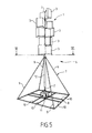
- the foot 7 of the wind turbine 6 is of square pyramidal shape, and comprises a square base frame 8, and four uprights 9 forming the edges directed towards the top of the pyramid.
- Reinforcing elements 10 connect opposite edges of the base frame 8 to reinforce its structure.
- a set of electric generator 11 dynamo type is mounted in the center of the base frame 8.
- a hollow vertical tube 12 is attached at its upper end to the top of the pyramid and is directed towards the center of the base frame 8 and the electric generator assembly 11.
- the axis 2 of the rotor element is introduced inside the tube 12, and is able to rotate therein by means of bearings 13 disposed inside the hollow tube 12, the tube 12 acting as a guide for the rotation of axis 2.
- the wind turbine 6 being placed outside, the action of the wind on the rotor element 1 will cause a rotation thereof, which will be transmitted to all electric generator 11 by the axis 2 of the rotor element, in a manner known for vertical axis wind turbines.
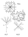
- FIGS. 7 and 8 schematically illustrate another application of the rotor element according to the present invention on a wind turbine called shrub.
- a vertical axis wind turbine 60 consists of a vertical axis 2, at the top of which four branches 61 are fixed, each branch 61 being constituted by a rotor element according to the invention, with a plurality of blades 3 shown. schematically to facilitate the reading of the Figure.
- Each rotor element 61 is fixed relative to the axis 2 of the wind turbine 60, but the action of the wind flow on the blades 3 of the rotor elements 61 will cause the rotation of the axis 2, which , as for the wind turbine Figures 5 and 6 , is connected to an electric generator system (not shown).
- the blade 300 consists, as for the blades of the other variants, of two fins 500, symmetrical with respect to the axis 2 on which the blade 300 is assembled, the two fins 500 being assembled on the axis 2 following a lateral border thereof.
- Each fin 500 consists of three surfaces 500a, 500b and 500c, each surface 500a, 500b, 500c consisting of two facets 500a1, 500a2 for the first surface 500a, 500b1, 500b2 for the second surface 500b, and 500c1, 500c2 for the third surface 500c.
- the two facets of each surface 500a, 500b, 500c are orthogonal to one another on a common border, the common edges of the facets 500a1, 500a2, 500b1, 500b2, 500c1, 500c2 all belonging to the same plane orthogonal to the axis 2.
- the first surface 500a is fixed to the fixing element 400 on the axis 2 so that the plane Pa forming an angle of 45 ° with the two facets 500a1 and 500a2 of the first surface 500a contains the axis 2, the plane Pb forming an angle of 45 ° with the facets 500b1 and 500b2 of the second surface 500b being orthogonal to the plane Pa, and the plane Pc forming an angle of 45 ° with the facets 500c1 and 500c2 of the third surface 500c forming an angle d approximately 120 ° with the plane Pb of the fin 500, the first and third surfaces 500a and 500c being located on the same side of the plane Pb of the second surface 500b.
- a flange 500d is formed continuously on the lower and upper edges of the first, second and third surfaces 500a, 500b and 500c, corresponding to the edges of the fin 500 orthogonal to the axis 2 of the rotor member 1, such that the flange 500d is oriented towards the closed side of the fin 500 corresponding to the side of the fin 500 where the planes Pa and Pb form an angle of 90 °.
Landscapes
- Engineering & Computer Science (AREA)
- Life Sciences & Earth Sciences (AREA)
- Sustainable Development (AREA)
- Sustainable Energy (AREA)
- Chemical & Material Sciences (AREA)
- Combustion & Propulsion (AREA)
- Mechanical Engineering (AREA)
- General Engineering & Computer Science (AREA)
- Physics & Mathematics (AREA)
- Fluid Mechanics (AREA)
- Wind Motors (AREA)
Claims (9)
- Rotorelement (1) für ein Energieerzeugungssystem (6; 60), das Folgendes umfasst:- eine Achse (2);- eine Vielzahl von identischen Blättern (3; 30; 300), die an der Achse (2) befestigt sind, wobei die Blätter (3; 30; 300) nebeneinander hintereinander an der Achse (2) angeordnet sind und an dieser angrenzen;- wobei jedes Blatt (3; 30; 300) aus zwei zur Achse (2) symmetrischen Flügeln (5; 50; 500) gebildet ist, die an der Achse (2) montiert sind;- wobei die Blätter (3; 30; 300) an der Achse (2) des Rotorelements (1) von einem ersten Blatt (3; 30; 300) ausgehend, das sich an einem Ende an der Achse (2) des Rotorelements (1) befindet, derart angeordnet sind, dass bei zwei an der Achse (2) aufeinanderfolgenden Blättern (3; 30; 300) die Mittelebenen der beiden Blätter (3; 30; 300), die die Achse (2) enthalten, einen gleichbleibenden Winkel bilden,dadurch gekennzeichnet, dass jeder Flügel (5; 50; 500) eines Blatts (3; 30; 300) eine erste Fläche (5a; 50a; 500a), eine zweite Fläche (5b; 50b; 500b) rechtwinklig zur ersten Fläche (5a; 50a; 500a) und eine dritte Fläche (5c; 50c; 500c) umfasst, die einen Winkel mit der zweiten Fläche (5b; 50b; 500b) bildet und sich auf derselben Seite der Ebene, die von der zweiten Fläche (5b; 50b; 500b) gebildet wird, wie die erste Fläche (5a; 50a; 500a) befindet.
- Rotorelement (1) nach Anspruch 1, dadurch gekennzeichnet, dass der Winkel, der zwischen den Mittelebenen der beiden Blätter (3; 30; 300) gebildet wird, die an der Achse (2) aufeinander folgen, und die die Achse (2) enthalten, 360° geteilt durch die Anzahl der Blätter (3; 30) an der Achse (2) entspricht.
- Rotorelement (1) nach einem der Ansprüche 1 oder 2, dadurch gekennzeichnet, dass die erste (5a), zweite (5b) und dritte Fläche (5c) jedes Flügels (5) rechteckig sind.
- Rotorelement (1) nach Anspruch 3, dadurch gekennzeichnet, dass die Flächen (5a, 5b, 5c) jedes Flügels (5) eine gemeinsame Abmessung in der Richtung der Achse (2) aufweisen.
- Rotorelement (1) nach einem der Ansprüche 1 oder 2, dadurch gekennzeichnet, dass die Abmessung jedes Flügels (50) in Richtung der Achse (2) von dem Ende des Flügels (50), das mit der Achse (2) verbunden ist, zu dem freien Ende des Flügels (50) hin kontinuierlich größer wird.
- Rotorelement nach einem der Ansprüche 1 oder 2, dadurch gekennzeichnet, dass jede Fläche (500a, 500b, 500c) des Flügels (500) aus zwei kleinen Flächen (500a1, 500a2; 500b1, 500b2; 500c1, 500c2) gebildet ist, die rechtwinklig zueinander verlaufen, wobei die gemeinsamen Ränder der kleinen Flächen (500a1, 500a2) der ersten Fläche (500a), der kleinen Flächen (500b1, 500b2) der zweiten Fläche (500b) und der kleinen Flächen (500c1, 500c2) der dritten Fläche (500c) alle zu ein und derselben Ebene rechtwinklig zur Achse (2) zugehörig sind.
- Rotorelement (1) nach einem der Ansprüche 3 bis 6, dadurch gekennzeichnet, dass jeder Flügel (5; 50; 500) eine rechtwinklige Abwinklung an den nicht parallel zur Achse verlaufenden Rändern der ersten, zweiten und dritten Fläche (5a, 5b, 5c; 50a, 50b, 50c; 500a, 500b, 500c) umfasst, wobei die rechtwinklige Abwinklung zu der Seite des Flügels (5; 50; 500), bei der die erste und zweite Fläche (5a, 5b; 50a, 50b; 500a, 500b) einen Winkel von 90° bilden, gerichtet ist.
- Vertikalachswindkraftanlage (6), dadurch gekennzeichnet, dass das Rotorelement (1) nach einem der Ansprüche 1 bis 7 den Rotor (1) der Windkraftanlage (6) bildet.
- Vertikalachswindkraftanlage (60), das eine Vertikalachse (2) umfasst, die an einem unteren Ende mit einem Generator (11) verbunden ist und an ihrem oberen Ende ein oder mehrere Arme (61) umfasst, der jeweils von einem Rotorelement (1) nach einem der Ansprüche 1 bis 7 gebildet ist.
Applications Claiming Priority (2)
| Application Number | Priority Date | Filing Date | Title |
|---|---|---|---|
| FR0959112A FR2954399B1 (fr) | 2009-12-17 | 2009-12-17 | Element de rotor pour systeme de production d'energie et systeme de production d'energie l'utilisant |
| PCT/FR2010/052781 WO2011073588A2 (fr) | 2009-12-17 | 2010-12-17 | Element de rotor pour systeme de production d'energie et systeme de production d'energie l'utilisant |
Publications (2)
| Publication Number | Publication Date |
|---|---|
| EP2513472A2 EP2513472A2 (de) | 2012-10-24 |
| EP2513472B1 true EP2513472B1 (de) | 2014-10-29 |
Family
ID=42487919
Family Applications (1)
| Application Number | Title | Priority Date | Filing Date |
|---|---|---|---|
| EP10807609.2A Not-in-force EP2513472B1 (de) | 2009-12-17 | 2010-12-17 | Rotorelement für ein energieerzeugungssystem und energieerzeugungssystem dafür |
Country Status (3)
| Country | Link |
|---|---|
| EP (1) | EP2513472B1 (de) |
| FR (1) | FR2954399B1 (de) |
| WO (1) | WO2011073588A2 (de) |
Family Cites Families (3)
| Publication number | Priority date | Publication date | Assignee | Title |
|---|---|---|---|---|
| FR2442979A2 (fr) * | 1977-03-25 | 1980-06-27 | Voukourakos Constantin | Anemoalternateur |
| GB2412948B (en) * | 2004-04-08 | 2007-02-28 | Alfred Learmonth | Wind or water motor |
| US7381030B1 (en) * | 2004-07-30 | 2008-06-03 | Vanderhye Robert A | Wind turbine shroud |
-
2009
- 2009-12-17 FR FR0959112A patent/FR2954399B1/fr not_active Expired - Fee Related
-
2010
- 2010-12-17 WO PCT/FR2010/052781 patent/WO2011073588A2/fr not_active Ceased
- 2010-12-17 EP EP10807609.2A patent/EP2513472B1/de not_active Not-in-force
Also Published As
| Publication number | Publication date |
|---|---|
| WO2011073588A2 (fr) | 2011-06-23 |
| WO2011073588A3 (fr) | 2011-10-27 |
| EP2513472A2 (de) | 2012-10-24 |
| FR2954399A1 (fr) | 2011-06-24 |
| FR2954399B1 (fr) | 2012-10-19 |
Similar Documents
| Publication | Publication Date | Title |
|---|---|---|
| FR2988144A1 (fr) | Aerogenerateur comprenant un tronc et une pluralite de branches s'etendant a partir de ce tronc. | |
| CA2981545A1 (fr) | Troncon de mat d'eolienne, mat d'eolienne et procede d'assemblage | |
| CA2719144C (fr) | Pale pour appareil de generation d'energie, a partir d'un fluide, et appareil comprenant un rotor faisant application de telles pales | |
| FR2982649A1 (fr) | Dispositif de recuperation d'energie a partir d'un fluide en mouvement | |
| EP1567767A1 (de) | Wasserrad | |
| EP2513472B1 (de) | Rotorelement für ein energieerzeugungssystem und energieerzeugungssystem dafür | |
| FR2908840A1 (fr) | Eolienne a axe vertical avec enceinte pour environnement urbain | |
| EP3645872B1 (de) | Windturbinenturmabschnitt, windturbinenturm und montageverfahren | |
| WO2000004323A1 (fr) | Dispositif mixte, statique/dynamique pour l'evacuation de fluides gazeux | |
| FR2965592A1 (fr) | Eolienne | |
| FR3083291A1 (fr) | Systeme de connexion pour elements de forme allongee | |
| EP2665924A1 (de) | Stromanlage zur ausbeutung eines fluidstroms | |
| OA16237A (fr) | Elément de rotor pour système de production d'énergie et système de production d'énergie l'utilisant. | |
| WO2010149894A1 (fr) | Dispositif d'eolienne de toiture | |
| EP3874163B1 (de) | Windturbinenturmabschnitt, windturbinenturm und montageverfahren | |
| EP3874164B1 (de) | Windturbinenturmabschnitt, windturbinenturm und montageverfahren | |
| FR3006718A1 (fr) | Eolienne a axe vertical | |
| EP1295013A1 (de) | Schraubenförmiger energiekonverter mit umfangseitigen rinnen | |
| FR2848260A1 (fr) | Dispositif concentrateur de vent notamment pour eolienne a axe vertical | |
| EP1813740A1 (de) | Unterstand | |
| FR2520057A1 (fr) | Perfectionnement aux aerogenerateurs | |
| WO2012001320A1 (fr) | Eolienne verticale a winglets | |
| CA2138483C (fr) | Scie circulaire avec dents multi-pointes ajustables | |
| FR2888292A1 (fr) | Turbine-eolienne : appareil mu par le vent pour la production d'energie electrique | |
| FR2651610A1 (fr) | Module de connexion pour conducteurs electriques. |
Legal Events
| Date | Code | Title | Description |
|---|---|---|---|
| PUAI | Public reference made under article 153(3) epc to a published international application that has entered the european phase |
Free format text: ORIGINAL CODE: 0009012 |
|
| 17P | Request for examination filed |
Effective date: 20120713 |
|
| AK | Designated contracting states |
Kind code of ref document: A2 Designated state(s): AL AT BE BG CH CY CZ DE DK EE ES FI FR GB GR HR HU IE IS IT LI LT LU LV MC MK MT NL NO PL PT RO RS SE SI SK SM TR |
|
| DAX | Request for extension of the european patent (deleted) | ||
| REG | Reference to a national code |
Ref country code: DE Ref legal event code: R079 Ref document number: 602010019870 Country of ref document: DE Free format text: PREVIOUS MAIN CLASS: F03D0003000000 Ipc: F03B0007000000 |
|
| GRAP | Despatch of communication of intention to grant a patent |
Free format text: ORIGINAL CODE: EPIDOSNIGR1 |
|
| RIC1 | Information provided on ipc code assigned before grant |
Ipc: F03B 7/00 20060101AFI20140506BHEP |
|
| INTG | Intention to grant announced |
Effective date: 20140519 |
|
| GRAS | Grant fee paid |
Free format text: ORIGINAL CODE: EPIDOSNIGR3 |
|
| GRAA | (expected) grant |
Free format text: ORIGINAL CODE: 0009210 |
|
| AK | Designated contracting states |
Kind code of ref document: B1 Designated state(s): AL AT BE BG CH CY CZ DE DK EE ES FI FR GB GR HR HU IE IS IT LI LT LU LV MC MK MT NL NO PL PT RO RS SE SI SK SM TR |
|
| REG | Reference to a national code |
Ref country code: GB Ref legal event code: FG4D Free format text: NOT ENGLISH |
|
| REG | Reference to a national code |
Ref country code: CH Ref legal event code: EP |
|
| REG | Reference to a national code |
Ref country code: AT Ref legal event code: REF Ref document number: 693745 Country of ref document: AT Kind code of ref document: T Effective date: 20141115 |
|
| REG | Reference to a national code |
Ref country code: IE Ref legal event code: FG4D Free format text: LANGUAGE OF EP DOCUMENT: FRENCH |
|
| REG | Reference to a national code |
Ref country code: DE Ref legal event code: R096 Ref document number: 602010019870 Country of ref document: DE Effective date: 20141211 |
|
| PGFP | Annual fee paid to national office [announced via postgrant information from national office to epo] |
Ref country code: GB Payment date: 20141230 Year of fee payment: 5 |
|
| REG | Reference to a national code |
Ref country code: AT Ref legal event code: MK05 Ref document number: 693745 Country of ref document: AT Kind code of ref document: T Effective date: 20141029 |
|
| REG | Reference to a national code |
Ref country code: NL Ref legal event code: VDEP Effective date: 20141029 |
|
| REG | Reference to a national code |
Ref country code: LT Ref legal event code: MG4D |
|
| PG25 | Lapsed in a contracting state [announced via postgrant information from national office to epo] |
Ref country code: NL Free format text: LAPSE BECAUSE OF FAILURE TO SUBMIT A TRANSLATION OF THE DESCRIPTION OR TO PAY THE FEE WITHIN THE PRESCRIBED TIME-LIMIT Effective date: 20141029 Ref country code: NO Free format text: LAPSE BECAUSE OF FAILURE TO SUBMIT A TRANSLATION OF THE DESCRIPTION OR TO PAY THE FEE WITHIN THE PRESCRIBED TIME-LIMIT Effective date: 20150129 Ref country code: LT Free format text: LAPSE BECAUSE OF FAILURE TO SUBMIT A TRANSLATION OF THE DESCRIPTION OR TO PAY THE FEE WITHIN THE PRESCRIBED TIME-LIMIT Effective date: 20141029 Ref country code: FI Free format text: LAPSE BECAUSE OF FAILURE TO SUBMIT A TRANSLATION OF THE DESCRIPTION OR TO PAY THE FEE WITHIN THE PRESCRIBED TIME-LIMIT Effective date: 20141029 Ref country code: ES Free format text: LAPSE BECAUSE OF FAILURE TO SUBMIT A TRANSLATION OF THE DESCRIPTION OR TO PAY THE FEE WITHIN THE PRESCRIBED TIME-LIMIT Effective date: 20141029 Ref country code: IS Free format text: LAPSE BECAUSE OF FAILURE TO SUBMIT A TRANSLATION OF THE DESCRIPTION OR TO PAY THE FEE WITHIN THE PRESCRIBED TIME-LIMIT Effective date: 20150228 Ref country code: PT Free format text: LAPSE BECAUSE OF FAILURE TO SUBMIT A TRANSLATION OF THE DESCRIPTION OR TO PAY THE FEE WITHIN THE PRESCRIBED TIME-LIMIT Effective date: 20150302 |
|
| PGFP | Annual fee paid to national office [announced via postgrant information from national office to epo] |
Ref country code: DE Payment date: 20141229 Year of fee payment: 5 |
|
| PG25 | Lapsed in a contracting state [announced via postgrant information from national office to epo] |
Ref country code: LV Free format text: LAPSE BECAUSE OF FAILURE TO SUBMIT A TRANSLATION OF THE DESCRIPTION OR TO PAY THE FEE WITHIN THE PRESCRIBED TIME-LIMIT Effective date: 20141029 Ref country code: CY Free format text: LAPSE BECAUSE OF FAILURE TO SUBMIT A TRANSLATION OF THE DESCRIPTION OR TO PAY THE FEE WITHIN THE PRESCRIBED TIME-LIMIT Effective date: 20141029 Ref country code: HR Free format text: LAPSE BECAUSE OF FAILURE TO SUBMIT A TRANSLATION OF THE DESCRIPTION OR TO PAY THE FEE WITHIN THE PRESCRIBED TIME-LIMIT Effective date: 20141029 Ref country code: PL Free format text: LAPSE BECAUSE OF FAILURE TO SUBMIT A TRANSLATION OF THE DESCRIPTION OR TO PAY THE FEE WITHIN THE PRESCRIBED TIME-LIMIT Effective date: 20141029 Ref country code: RS Free format text: LAPSE BECAUSE OF FAILURE TO SUBMIT A TRANSLATION OF THE DESCRIPTION OR TO PAY THE FEE WITHIN THE PRESCRIBED TIME-LIMIT Effective date: 20141029 Ref country code: SE Free format text: LAPSE BECAUSE OF FAILURE TO SUBMIT A TRANSLATION OF THE DESCRIPTION OR TO PAY THE FEE WITHIN THE PRESCRIBED TIME-LIMIT Effective date: 20141029 Ref country code: GR Free format text: LAPSE BECAUSE OF FAILURE TO SUBMIT A TRANSLATION OF THE DESCRIPTION OR TO PAY THE FEE WITHIN THE PRESCRIBED TIME-LIMIT Effective date: 20150130 Ref country code: AT Free format text: LAPSE BECAUSE OF FAILURE TO SUBMIT A TRANSLATION OF THE DESCRIPTION OR TO PAY THE FEE WITHIN THE PRESCRIBED TIME-LIMIT Effective date: 20141029 |
|
| PGFP | Annual fee paid to national office [announced via postgrant information from national office to epo] |
Ref country code: FR Payment date: 20141223 Year of fee payment: 5 |
|
| PG25 | Lapsed in a contracting state [announced via postgrant information from national office to epo] |
Ref country code: BE Free format text: LAPSE BECAUSE OF NON-PAYMENT OF DUE FEES Effective date: 20141231 |
|
| REG | Reference to a national code |
Ref country code: DE Ref legal event code: R097 Ref document number: 602010019870 Country of ref document: DE |
|
| PG25 | Lapsed in a contracting state [announced via postgrant information from national office to epo] |
Ref country code: RO Free format text: LAPSE BECAUSE OF FAILURE TO SUBMIT A TRANSLATION OF THE DESCRIPTION OR TO PAY THE FEE WITHIN THE PRESCRIBED TIME-LIMIT Effective date: 20141029 Ref country code: CZ Free format text: LAPSE BECAUSE OF FAILURE TO SUBMIT A TRANSLATION OF THE DESCRIPTION OR TO PAY THE FEE WITHIN THE PRESCRIBED TIME-LIMIT Effective date: 20141029 Ref country code: EE Free format text: LAPSE BECAUSE OF FAILURE TO SUBMIT A TRANSLATION OF THE DESCRIPTION OR TO PAY THE FEE WITHIN THE PRESCRIBED TIME-LIMIT Effective date: 20141029 Ref country code: LU Free format text: LAPSE BECAUSE OF FAILURE TO SUBMIT A TRANSLATION OF THE DESCRIPTION OR TO PAY THE FEE WITHIN THE PRESCRIBED TIME-LIMIT Effective date: 20141217 Ref country code: DK Free format text: LAPSE BECAUSE OF FAILURE TO SUBMIT A TRANSLATION OF THE DESCRIPTION OR TO PAY THE FEE WITHIN THE PRESCRIBED TIME-LIMIT Effective date: 20141029 Ref country code: SK Free format text: LAPSE BECAUSE OF FAILURE TO SUBMIT A TRANSLATION OF THE DESCRIPTION OR TO PAY THE FEE WITHIN THE PRESCRIBED TIME-LIMIT Effective date: 20141029 |
|
| REG | Reference to a national code |
Ref country code: CH Ref legal event code: PL |
|
| PG25 | Lapsed in a contracting state [announced via postgrant information from national office to epo] |
Ref country code: IT Free format text: LAPSE BECAUSE OF FAILURE TO SUBMIT A TRANSLATION OF THE DESCRIPTION OR TO PAY THE FEE WITHIN THE PRESCRIBED TIME-LIMIT Effective date: 20141029 |
|
| PLBE | No opposition filed within time limit |
Free format text: ORIGINAL CODE: 0009261 |
|
| STAA | Information on the status of an ep patent application or granted ep patent |
Free format text: STATUS: NO OPPOSITION FILED WITHIN TIME LIMIT |
|
| REG | Reference to a national code |
Ref country code: IE Ref legal event code: MM4A |
|
| 26N | No opposition filed |
Effective date: 20150730 |
|
| PG25 | Lapsed in a contracting state [announced via postgrant information from national office to epo] |
Ref country code: IE Free format text: LAPSE BECAUSE OF NON-PAYMENT OF DUE FEES Effective date: 20141217 Ref country code: CH Free format text: LAPSE BECAUSE OF NON-PAYMENT OF DUE FEES Effective date: 20141231 Ref country code: LI Free format text: LAPSE BECAUSE OF NON-PAYMENT OF DUE FEES Effective date: 20141231 |
|
| PG25 | Lapsed in a contracting state [announced via postgrant information from national office to epo] |
Ref country code: SI Free format text: LAPSE BECAUSE OF FAILURE TO SUBMIT A TRANSLATION OF THE DESCRIPTION OR TO PAY THE FEE WITHIN THE PRESCRIBED TIME-LIMIT Effective date: 20141029 |
|
| PG25 | Lapsed in a contracting state [announced via postgrant information from national office to epo] |
Ref country code: SM Free format text: LAPSE BECAUSE OF FAILURE TO SUBMIT A TRANSLATION OF THE DESCRIPTION OR TO PAY THE FEE WITHIN THE PRESCRIBED TIME-LIMIT Effective date: 20141029 |
|
| PG25 | Lapsed in a contracting state [announced via postgrant information from national office to epo] |
Ref country code: MC Free format text: LAPSE BECAUSE OF FAILURE TO SUBMIT A TRANSLATION OF THE DESCRIPTION OR TO PAY THE FEE WITHIN THE PRESCRIBED TIME-LIMIT Effective date: 20141029 |
|
| PG25 | Lapsed in a contracting state [announced via postgrant information from national office to epo] |
Ref country code: BG Free format text: LAPSE BECAUSE OF FAILURE TO SUBMIT A TRANSLATION OF THE DESCRIPTION OR TO PAY THE FEE WITHIN THE PRESCRIBED TIME-LIMIT Effective date: 20141029 |
|
| REG | Reference to a national code |
Ref country code: DE Ref legal event code: R119 Ref document number: 602010019870 Country of ref document: DE |
|
| PG25 | Lapsed in a contracting state [announced via postgrant information from national office to epo] |
Ref country code: MT Free format text: LAPSE BECAUSE OF FAILURE TO SUBMIT A TRANSLATION OF THE DESCRIPTION OR TO PAY THE FEE WITHIN THE PRESCRIBED TIME-LIMIT Effective date: 20141029 Ref country code: TR Free format text: LAPSE BECAUSE OF FAILURE TO SUBMIT A TRANSLATION OF THE DESCRIPTION OR TO PAY THE FEE WITHIN THE PRESCRIBED TIME-LIMIT Effective date: 20141029 Ref country code: HU Free format text: LAPSE BECAUSE OF FAILURE TO SUBMIT A TRANSLATION OF THE DESCRIPTION OR TO PAY THE FEE WITHIN THE PRESCRIBED TIME-LIMIT; INVALID AB INITIO Effective date: 20101217 |
|
| GBPC | Gb: european patent ceased through non-payment of renewal fee |
Effective date: 20151217 |
|
| REG | Reference to a national code |
Ref country code: FR Ref legal event code: ST Effective date: 20160831 |
|
| PG25 | Lapsed in a contracting state [announced via postgrant information from national office to epo] |
Ref country code: GB Free format text: LAPSE BECAUSE OF NON-PAYMENT OF DUE FEES Effective date: 20151217 Ref country code: DE Free format text: LAPSE BECAUSE OF NON-PAYMENT OF DUE FEES Effective date: 20160701 |
|
| PG25 | Lapsed in a contracting state [announced via postgrant information from national office to epo] |
Ref country code: FR Free format text: LAPSE BECAUSE OF NON-PAYMENT OF DUE FEES Effective date: 20151231 |
|
| PG25 | Lapsed in a contracting state [announced via postgrant information from national office to epo] |
Ref country code: MK Free format text: LAPSE BECAUSE OF FAILURE TO SUBMIT A TRANSLATION OF THE DESCRIPTION OR TO PAY THE FEE WITHIN THE PRESCRIBED TIME-LIMIT Effective date: 20141029 |
|
| PG25 | Lapsed in a contracting state [announced via postgrant information from national office to epo] |
Ref country code: AL Free format text: LAPSE BECAUSE OF FAILURE TO SUBMIT A TRANSLATION OF THE DESCRIPTION OR TO PAY THE FEE WITHIN THE PRESCRIBED TIME-LIMIT Effective date: 20141029 |