EP2513401B1 - Profiled spacer and insulation glazing assembly with such a profiled spacer - Google Patents
Profiled spacer and insulation glazing assembly with such a profiled spacer Download PDFInfo
- Publication number
- EP2513401B1 EP2513401B1 EP11776113.0A EP11776113A EP2513401B1 EP 2513401 B1 EP2513401 B1 EP 2513401B1 EP 11776113 A EP11776113 A EP 11776113A EP 2513401 B1 EP2513401 B1 EP 2513401B1
- Authority
- EP
- European Patent Office
- Prior art keywords
- wall
- diffusion barrier
- layer
- barrier layer
- thickness
- Prior art date
- Legal status (The legal status is an assumption and is not a legal conclusion. Google has not performed a legal analysis and makes no representation as to the accuracy of the status listed.)
- Active
Links
- 125000006850 spacer group Chemical group 0.000 title claims description 151
- 238000009413 insulation Methods 0.000 title description 6
- 238000009792 diffusion process Methods 0.000 claims description 159
- 230000004888 barrier function Effects 0.000 claims description 152
- 239000000463 material Substances 0.000 claims description 66
- 238000005452 bending Methods 0.000 claims description 41
- 230000002787 reinforcement Effects 0.000 claims description 33
- 239000007769 metal material Substances 0.000 claims description 22
- 229920003023 plastic Polymers 0.000 claims description 19
- 239000004033 plastic Substances 0.000 claims description 19
- 230000007935 neutral effect Effects 0.000 claims description 15
- 229920000098 polyolefin Polymers 0.000 claims description 7
- 239000000853 adhesive Substances 0.000 claims description 6
- 230000001070 adhesive effect Effects 0.000 claims description 6
- 229920002994 synthetic fiber Polymers 0.000 claims 1
- 230000003014 reinforcing effect Effects 0.000 description 154
- 229920000219 Ethylene vinyl alcohol Polymers 0.000 description 32
- UFRKOOWSQGXVKV-UHFFFAOYSA-N ethene;ethenol Chemical compound C=C.OC=C UFRKOOWSQGXVKV-UHFFFAOYSA-N 0.000 description 30
- 239000004715 ethylene vinyl alcohol Substances 0.000 description 30
- XLYOFNOQVPJJNP-UHFFFAOYSA-N water Substances O XLYOFNOQVPJJNP-UHFFFAOYSA-N 0.000 description 20
- 239000000835 fiber Substances 0.000 description 12
- 229910001868 water Inorganic materials 0.000 description 12
- 239000004743 Polypropylene Substances 0.000 description 10
- 229910052751 metal Inorganic materials 0.000 description 9
- 239000002184 metal Substances 0.000 description 9
- 239000004698 Polyethylene Substances 0.000 description 8
- VGGSQFUCUMXWEO-UHFFFAOYSA-N Ethene Chemical compound C=C VGGSQFUCUMXWEO-UHFFFAOYSA-N 0.000 description 7
- 239000005977 Ethylene Substances 0.000 description 7
- 239000002318 adhesion promoter Substances 0.000 description 7
- 238000001125 extrusion Methods 0.000 description 7
- 239000007789 gas Substances 0.000 description 7
- 229910052782 aluminium Inorganic materials 0.000 description 6
- XAGFODPZIPBFFR-UHFFFAOYSA-N aluminium Chemical compound [Al] XAGFODPZIPBFFR-UHFFFAOYSA-N 0.000 description 6
- 238000000034 method Methods 0.000 description 6
- 230000008569 process Effects 0.000 description 6
- 229910001220 stainless steel Inorganic materials 0.000 description 5
- 239000010935 stainless steel Substances 0.000 description 5
- XKRFYHLGVUSROY-UHFFFAOYSA-N Argon Chemical compound [Ar] XKRFYHLGVUSROY-UHFFFAOYSA-N 0.000 description 4
- IJGRMHOSHXDMSA-UHFFFAOYSA-N Atomic nitrogen Chemical compound N#N IJGRMHOSHXDMSA-UHFFFAOYSA-N 0.000 description 4
- 230000015572 biosynthetic process Effects 0.000 description 4
- 239000002131 composite material Substances 0.000 description 4
- 239000011888 foil Substances 0.000 description 4
- -1 polypropylene Polymers 0.000 description 4
- 239000003566 sealing material Substances 0.000 description 4
- 239000007767 bonding agent Substances 0.000 description 3
- 239000011248 coating agent Substances 0.000 description 3
- 238000000576 coating method Methods 0.000 description 3
- 238000003475 lamination Methods 0.000 description 3
- 238000004519 manufacturing process Methods 0.000 description 3
- 230000007704 transition Effects 0.000 description 3
- 238000007740 vapor deposition Methods 0.000 description 3
- 238000003466 welding Methods 0.000 description 3
- 229910000831 Steel Inorganic materials 0.000 description 2
- 238000004026 adhesive bonding Methods 0.000 description 2
- 229910052786 argon Inorganic materials 0.000 description 2
- QVGXLLKOCUKJST-UHFFFAOYSA-N atomic oxygen Chemical compound [O] QVGXLLKOCUKJST-UHFFFAOYSA-N 0.000 description 2
- 239000004020 conductor Substances 0.000 description 2
- 230000001419 dependent effect Effects 0.000 description 2
- 238000005304 joining Methods 0.000 description 2
- 229910052757 nitrogen Inorganic materials 0.000 description 2
- 239000001301 oxygen Substances 0.000 description 2
- 229910052760 oxygen Inorganic materials 0.000 description 2
- 229920001155 polypropylene Polymers 0.000 description 2
- 230000002441 reversible effect Effects 0.000 description 2
- 239000000565 sealant Substances 0.000 description 2
- 239000010959 steel Substances 0.000 description 2
- VYZAMTAEIAYCRO-UHFFFAOYSA-N Chromium Chemical compound [Cr] VYZAMTAEIAYCRO-UHFFFAOYSA-N 0.000 description 1
- 229920005372 Plexiglas® Polymers 0.000 description 1
- 239000004952 Polyamide Substances 0.000 description 1
- 229920002367 Polyisobutene Polymers 0.000 description 1
- ATJFFYVFTNAWJD-UHFFFAOYSA-N Tin Chemical compound [Sn] ATJFFYVFTNAWJD-UHFFFAOYSA-N 0.000 description 1
- HCHKCACWOHOZIP-UHFFFAOYSA-N Zinc Chemical compound [Zn] HCHKCACWOHOZIP-UHFFFAOYSA-N 0.000 description 1
- 238000010521 absorption reaction Methods 0.000 description 1
- 230000002411 adverse Effects 0.000 description 1
- 239000012080 ambient air Substances 0.000 description 1
- 125000000484 butyl group Chemical group [H]C([*])([H])C([H])([H])C([H])([H])C([H])([H])[H] 0.000 description 1
- 230000008859 change Effects 0.000 description 1
- ZCDOYSPFYFSLEW-UHFFFAOYSA-N chromate(2-) Chemical compound [O-][Cr]([O-])(=O)=O ZCDOYSPFYFSLEW-UHFFFAOYSA-N 0.000 description 1
- 229910052804 chromium Inorganic materials 0.000 description 1
- 239000011651 chromium Substances 0.000 description 1
- 238000010276 construction Methods 0.000 description 1
- 238000005260 corrosion Methods 0.000 description 1
- 230000007797 corrosion Effects 0.000 description 1
- 230000002542 deteriorative effect Effects 0.000 description 1
- 238000011161 development Methods 0.000 description 1
- 230000018109 developmental process Effects 0.000 description 1
- 230000000694 effects Effects 0.000 description 1
- 238000005246 galvanizing Methods 0.000 description 1
- 239000011521 glass Substances 0.000 description 1
- 230000006872 improvement Effects 0.000 description 1
- 239000011261 inert gas Substances 0.000 description 1
- 229910052743 krypton Inorganic materials 0.000 description 1
- DNNSSWSSYDEUBZ-UHFFFAOYSA-N krypton atom Chemical compound [Kr] DNNSSWSSYDEUBZ-UHFFFAOYSA-N 0.000 description 1
- 238000010030 laminating Methods 0.000 description 1
- 150000002739 metals Chemical class 0.000 description 1
- NJPPVKZQTLUDBO-UHFFFAOYSA-N novaluron Chemical compound C1=C(Cl)C(OC(F)(F)C(OC(F)(F)F)F)=CC=C1NC(=O)NC(=O)C1=C(F)C=CC=C1F NJPPVKZQTLUDBO-UHFFFAOYSA-N 0.000 description 1
- 230000002093 peripheral effect Effects 0.000 description 1
- 230000035699 permeability Effects 0.000 description 1
- 239000002985 plastic film Substances 0.000 description 1
- 229920006255 plastic film Polymers 0.000 description 1
- 229920002647 polyamide Polymers 0.000 description 1
- 239000004417 polycarbonate Substances 0.000 description 1
- 229920000515 polycarbonate Polymers 0.000 description 1
- 239000005020 polyethylene terephthalate Substances 0.000 description 1
- 229920000139 polyethylene terephthalate Polymers 0.000 description 1
- 239000004926 polymethyl methacrylate Substances 0.000 description 1
- 229920001296 polysiloxane Polymers 0.000 description 1
- 229920001021 polysulfide Polymers 0.000 description 1
- 239000005077 polysulfide Substances 0.000 description 1
- 150000008117 polysulfides Polymers 0.000 description 1
- 238000005096 rolling process Methods 0.000 description 1
- 238000004544 sputter deposition Methods 0.000 description 1
- 230000000087 stabilizing effect Effects 0.000 description 1
- 239000005028 tinplate Substances 0.000 description 1
- 229910052724 xenon Inorganic materials 0.000 description 1
- FHNFHKCVQCLJFQ-UHFFFAOYSA-N xenon atom Chemical compound [Xe] FHNFHKCVQCLJFQ-UHFFFAOYSA-N 0.000 description 1
- 239000011701 zinc Substances 0.000 description 1
- 229910052725 zinc Inorganic materials 0.000 description 1
Images


Classifications
-
- E—FIXED CONSTRUCTIONS
- E06—DOORS, WINDOWS, SHUTTERS, OR ROLLER BLINDS IN GENERAL; LADDERS
- E06B—FIXED OR MOVABLE CLOSURES FOR OPENINGS IN BUILDINGS, VEHICLES, FENCES OR LIKE ENCLOSURES IN GENERAL, e.g. DOORS, WINDOWS, BLINDS, GATES
- E06B3/00—Window sashes, door leaves, or like elements for closing wall or like openings; Layout of fixed or moving closures, e.g. windows in wall or like openings; Features of rigidly-mounted outer frames relating to the mounting of wing frames
- E06B3/66—Units comprising two or more parallel glass or like panes permanently secured together
- E06B3/663—Elements for spacing panes
-
- E—FIXED CONSTRUCTIONS
- E04—BUILDING
- E04C—STRUCTURAL ELEMENTS; BUILDING MATERIALS
- E04C1/00—Building elements of block or other shape for the construction of parts of buildings
- E04C1/42—Building elements of block or other shape for the construction of parts of buildings of glass or other transparent material
-
- E—FIXED CONSTRUCTIONS
- E06—DOORS, WINDOWS, SHUTTERS, OR ROLLER BLINDS IN GENERAL; LADDERS
- E06B—FIXED OR MOVABLE CLOSURES FOR OPENINGS IN BUILDINGS, VEHICLES, FENCES OR LIKE ENCLOSURES IN GENERAL, e.g. DOORS, WINDOWS, BLINDS, GATES
- E06B3/00—Window sashes, door leaves, or like elements for closing wall or like openings; Layout of fixed or moving closures, e.g. windows in wall or like openings; Features of rigidly-mounted outer frames relating to the mounting of wing frames
- E06B3/66—Units comprising two or more parallel glass or like panes permanently secured together
- E06B3/663—Elements for spacing panes
- E06B3/66304—Discrete spacing elements, e.g. for evacuated glazing units
-
- E—FIXED CONSTRUCTIONS
- E06—DOORS, WINDOWS, SHUTTERS, OR ROLLER BLINDS IN GENERAL; LADDERS
- E06B—FIXED OR MOVABLE CLOSURES FOR OPENINGS IN BUILDINGS, VEHICLES, FENCES OR LIKE ENCLOSURES IN GENERAL, e.g. DOORS, WINDOWS, BLINDS, GATES
- E06B3/00—Window sashes, door leaves, or like elements for closing wall or like openings; Layout of fixed or moving closures, e.g. windows in wall or like openings; Features of rigidly-mounted outer frames relating to the mounting of wing frames
- E06B3/66—Units comprising two or more parallel glass or like panes permanently secured together
- E06B3/663—Elements for spacing panes
- E06B3/66309—Section members positioned at the edges of the glazing unit
- E06B3/66314—Section members positioned at the edges of the glazing unit of tubular shape
- E06B3/66319—Section members positioned at the edges of the glazing unit of tubular shape of rubber, plastics or similar materials
-
- E—FIXED CONSTRUCTIONS
- E06—DOORS, WINDOWS, SHUTTERS, OR ROLLER BLINDS IN GENERAL; LADDERS
- E06B—FIXED OR MOVABLE CLOSURES FOR OPENINGS IN BUILDINGS, VEHICLES, FENCES OR LIKE ENCLOSURES IN GENERAL, e.g. DOORS, WINDOWS, BLINDS, GATES
- E06B3/00—Window sashes, door leaves, or like elements for closing wall or like openings; Layout of fixed or moving closures, e.g. windows in wall or like openings; Features of rigidly-mounted outer frames relating to the mounting of wing frames
- E06B3/66—Units comprising two or more parallel glass or like panes permanently secured together
- E06B3/663—Elements for spacing panes
- E06B3/667—Connectors therefor
-
- E—FIXED CONSTRUCTIONS
- E06—DOORS, WINDOWS, SHUTTERS, OR ROLLER BLINDS IN GENERAL; LADDERS
- E06B—FIXED OR MOVABLE CLOSURES FOR OPENINGS IN BUILDINGS, VEHICLES, FENCES OR LIKE ENCLOSURES IN GENERAL, e.g. DOORS, WINDOWS, BLINDS, GATES
- E06B7/00—Special arrangements or measures in connection with doors or windows
- E06B7/12—Measures preventing the formation of condensed water
-
- E—FIXED CONSTRUCTIONS
- E06—DOORS, WINDOWS, SHUTTERS, OR ROLLER BLINDS IN GENERAL; LADDERS
- E06B—FIXED OR MOVABLE CLOSURES FOR OPENINGS IN BUILDINGS, VEHICLES, FENCES OR LIKE ENCLOSURES IN GENERAL, e.g. DOORS, WINDOWS, BLINDS, GATES
- E06B3/00—Window sashes, door leaves, or like elements for closing wall or like openings; Layout of fixed or moving closures, e.g. windows in wall or like openings; Features of rigidly-mounted outer frames relating to the mounting of wing frames
- E06B3/66—Units comprising two or more parallel glass or like panes permanently secured together
- E06B3/663—Elements for spacing panes
- E06B3/66309—Section members positioned at the edges of the glazing unit
- E06B2003/6638—Section members positioned at the edges of the glazing unit with coatings
Definitions
- the present invention relates to a spacer profile for use in insulating disk units having such a spacer profile and an insulating disk unit having such a spacer profile.
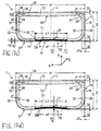
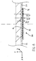
- Insulating disk units with at least two disks 151, 152 held in the insulating disk unit at a distance from each other are known (see FIG. 16 ).
- the discs 151, 152 are usually formed of inorganic or organic glass or other materials such as Plexiglas.
- the spacing of the disks 151, 152 is normally ensured by a spacer frame 150 formed of at least one composite spacer profile 100.
- Composite spacer profiles which are also referred to as composite spacer profiles, are provided as a diffusion barrier from a plastic profile and a metal layer, are eg in the DE 198 32 731 A1 (Family member WO 2000/005475 A1 ), of the EP 0 953 715 A2 (Family member US 6,196,652 ) or the EP 1 017 923 A1 (Family member US 6,339,909 ).
- the disc space 153 is preferably filled with an insulating inert gas such as argon, krypton, xenon, etc.
- the filling gas should not be able to escape from the space between the panes 153 even over a long period of time.
- the ambient air, or components of it, such as nitrogen, oxygen, water, etc. should not be able to penetrate into the space between the panes 153.
- the spacer profile 100 must be formed such that diffusion between the disk interior 153 and the environment is prevented. Spacer profiles therefore have a diffusion barrier 157, which prevents diffusion of the filling gas from the space between the panes 153 into the environment through the spacer profile 100.
- the discs 151, 152 and the spacer frame 150 plays a very large role.
- Insulating washer units which ensure high thermal insulation in the edge bond fulfill the so-called "warm edge” condition according to the meaning of the term in the art.
- the spacer profiles 100 should therefore have good thermal insulation.
- the spacer frame 150 is preferably bent from a one-piece spacer profile 100. To close the frame 150, the two ends of the spacer profile 100 are connected by means of a connector. If the spacer frame 150 is composed of a plurality of spacer profile pieces 100, multiple connectors are also necessary. Both in terms of manufacturing costs and with respect to the insulating properties, it is preferable to provide only one connection point.
- the bending of the frame 150 from the spacer profile 100 for example, by cold bending (at a room temperature of about 20 ° C).
- the problem of wrinkling on the bends occurs.
- the spacer profile should be bend with the least possible wrinkling and at the same time also have a high strength and flexural rigidity.
- spacers which have a comparatively thin continuous reinforcing layer of metal material on the profile body made of plastic. Such spacers lose their bending resistance by 90 ° in their diffusion-tightness and have comparatively thick plastic profile walls, so they do not sag too much.
- a spacer profile is known, the profile body consists of poor thermal conductivity material and is connected to a substantially over its entire width extending diffusion-tight layer of good heat conducting material.
- the diffusion-tight layer of good heat-conducting material has a region extending in the longitudinal direction of the spacer profile with reduced heat conduction transversely to the longitudinal direction of the spacer profile.
- An object of the invention is to provide an improved spacer profile, in which in particular the thermal insulation is improved with good strength or bending stiffness and good folding properties during bending.
- An insulating disk unit having such spacer profiles is another object of the invention.
- the diffusion-tightness is ensured on the one hand by a diffusion barrier, which is formed from the two reinforcing layers and the diffusion barrier layer and lies in bending the spacer profile in the neutral fiber.
- the hollow profile body may be at least partially made of a diffusion-tight plastic material, such as an EVOH material that ensures the diffusion-tightness.
- a diffusion barrier layer namely the part of the outer wall located between the reinforcing layers, is formed. The diffusion barrier layer transmits much less heat than the reinforcement layers.
- the spacer profile with the two mutually separated reinforcing layers, which are interconnected in a central region by means of a diffusion barrier layer has a substantially lower thermal conductivity, while maintaining the same diffusion-tightness, than a comparable conventional spacer profile. At the same time, the spacer profile becomes stiffer and stronger. Furthermore, material can be saved, whereby the manufacturing costs and weight can be reduced.
- the diffusion barrier layer By proper formation of the geometry of the hollow profile body and the reinforcing layers, the diffusion barrier layer, as the spacer is bent, lies approximately on the neutral fiber (the zone of material which does not strain or buckle upon bending) of the spacer profile. Therefore, in bending, substantially no tensile stresses act on the diffusion barrier layer. For this reason, a diffusion barrier layer can be used, which must absorb little or no tensile forces. In addition, the diffusion barrier layer can be easily applied to the spacer profile.
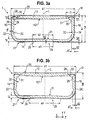
- the spacer profile 1 is in the FIG. 3a ) in cross section perpendicular to a longitudinal direction Z, ie, shown in section in an XY plane, which is from a transverse direction X which is perpendicular to the longitudinal direction Z and a height direction Y which is perpendicular to the transverse direction X and the longitudinal direction Z, is spanned.
- the spacer profile 1 extends in the embodiment in the longitudinal direction Z with a Symmetrieebene L, which is arranged centrally with respect to the transverse direction X and parallel to the longitudinal direction Z and the height direction Y runs.
- the spacer profile 1 has a hollow profile body 10 made of a plastic material which extends in the longitudinal direction Z with a constant cross-sectional shape and has a first width b1 in the transverse direction X and a first height h1 in the height direction Y.
- the hollow profile body 10 has in its height direction Y an inner wall 12 and on the inner wall 12 opposite side in the height direction Y an outer wall 14.
- the outer peripheral edges of the inner wall 12 and the outer wall 14 in the transverse direction X are connected to each other by a side wall 16, 18 which is substantially parallel to the height direction Y.
- the first side wall 16 lies in the transverse direction X with respect to the second side wall 18.
- the plane of symmetry L is substantially parallel to the side walls 16, 18 and is arranged centrally between them.
- the first side wall 16, the second side wall 18 and the outer wall 14 each have a first wall thickness s1.
- the inner wall 12 has a second wall thickness s2.
- the transitions or connecting portions of the side walls 16, 18 to the outer wall 14 are respectively rounded according to the first embodiment in the cross-sectional view, here formed substantially in the form of a quarter circle.
- a U-shape U-configuration
- the transitions or connecting portions between the side walls 16, 18 and the inner wall 12 are therefore in cross section to the longitudinal direction Z substantially at right angles, with a rounded connecting portion on the chamber 20 side facing formed.
- the hollow profile body 10 is preferably produced integrally by extrusion.
- the outer wall 14 is slightly concave with respect to the chamber 20 in this embodiment. That is, the outer wall 14 is curved in the direction of the interior of the chamber 20 in the height direction Y to form a curvature 21.
- the outer wall 14 is in the Center with respect to its edges in the transverse direction X, ie in the region of the plane of symmetry L, curved inwardly towards the chamber 20 by a second height h2.
- the inner wall 12 is slightly concave with respect to the chamber 20 in this embodiment. That the inner wall 12 is curved in the direction of the interior of the chamber 20 in the height direction Y to form a curvature 121.
- the inner wall 12 is centered with respect to its edges in the transverse direction X, i. in the region of the plane of symmetry L, curved inwardly towards the chamber 20 by a third height h3.
- the bulges 21 are already formed during the extrusion in the plastic. But they can also be formed directly after the extrusion or in a subsequent Rollumformvorgang.
- a first reinforcing layer 22 extends in one piece and continuous in the longitudinal direction Z with constant cross-section directly on the (the chamber facing away) outside of the first side wall 16 from just below the inner wall 12 to and directly on the first side wall 16 facing part of the (the chamber facing away) outside of the outer wall 14th
- a second reinforcing layer 24 extends integrally and continuously in the longitudinal direction Z with a constant cross section directly on the (side facing away from the chamber) outside of the second side wall 18 from just below the inner wall 12 to and directly on the second side wall 18 facing part of the ( Chamber off
- the first reinforcing layer 22 is formed from a first diffusion-proof metal material having a first specific thermal conductivity ⁇ 1
- the second reinforcing layer 24 is formed from a second diffusion-proof metal material
- vapor diffusion tightness or “diffusion-tight” is used herein with respect to the spacer profile or the spacer profile forming materials, in the following description are preferred both vapor diffusion tightness and gas diffusion tightness for the gases in question (for example, nitrogen, oxygen, Water, etc., especially argon).
- Gas or vapor diffusion-tight are the materials used, if preferably not more than 1% of the gases in the space between the panes 153 can escape within one year. Diffusion-tight is synonymous with low diffusion in the sense that the corresponding test standard EN 1279 Part 2 + 3 is preferably met. This means that the finished spacer profile preferably complies with the test standard EN 1279 part 2 + 3.
- the first and second reinforcing layers 22, 24 do not touch.
- the reinforcing layers 22, 24 are formed and arranged so as to be spaced apart from each other with respect to the transverse direction X at a first distance a1. That between the reinforcing layers 22, 24 remains on the outside of the outer wall 14 a with respect to the transverse direction X central region 25, which extends in the transverse direction X over the first distance a1, free.
- the central area 25 has a second width b2 in the transverse direction X, which corresponds to the first distance a1. In or on this central region 25 no reinforcing layer is formed or arranged.
- the reinforcing layers 22, 24 extend in this embodiment symmetrically with respect to the plane of symmetry L, so that the first reinforcing layer 22 and the second reinforcing layer 24 each have a distance al / 2 to the plane of symmetry L.
- the reinforcing layers 22, 24 are materially connected directly to the corresponding walls. As far as the term “cohesively directly connected” or “connected” is used here, in the following description is meant a direct connection without further intermediate layers.
- the first reinforcing layer 22 has a constant first thickness d1.
- the second reinforcing layer 24 has a constant second thickness d2.
- the first width b1 does not change since the hollow profile body 10 is formed at the edges in the transverse direction X in this embodiment such that the reinforcing layers 22, 24 do not increase the first width b1. That is, the region of the side walls 16, 18, on which no reinforcing layers 22, 24 are formed, is correspondingly wider.
- the reinforcing layers 22, 24 in the first embodiment have, at their end regions opposite to the outer wall 14 in the height direction Y, extended extension portions 28 extending in the longitudinal direction Z.
- the extension portions 28 extend the reinforcing layers 22, 24 in the height direction Y from just below the inner wall 12.
- profiled in this context means that the extension portion 28 is not exclusively a linear extension of the respective reinforcing layer 22, 24 in the height direction Y. but that in the two-dimensional representation of the cross section in the XY plane, a two-dimensional profile is formed, the example has one or more bends 29 of the extension portion 28.
- the extension portions 28 at the level of the inner wall 12 a 90 ° bend 29 in the direction of the plane of symmetry L in the inner wall 12. That the extension section 28 protrudes into the inner wall 12. It further has a groove 30 in the two-dimensional representation of the cross section in the X-Y plane.
- the extension portion 28 protrudes with a first length 11 in the transverse direction X from the outside of the corresponding side wall 16, 18 of the hollow profile body 10 in the inner wall 12 a.
- the extension sections 28 serve for improved bending behavior and improved adhesion of the reinforcement layers 22, 24, or in the hollow profile body 10. It is preferred if the extension sections 28 are as close as possible to the outside of the inner wall 12 facing away from the chamber 20 (as close as possible to the space between the panes 53), but covered by the material of the inner wall 12 are arranged.
- the extension sections 28 are each received in a receiving area 31.
- Such a receiving area 31 is formed by the inner wall 12 and / or side wall 16, 18 and extends from the outside of the inner wall 12 in the same and, if necessary, the corresponding side wall 16, 18 over a height in the height direction Y, which is smaller than 0, 4 h1, more preferably less than 0.2 h1 and more preferably less than 0.1 h1.
- the specified height of the receiving areas 31 also defines the beginning of the extension sections 28.
- the receiving areas 31 In the transverse direction X, the receiving areas 31 have at least the thickness s 1 of the side walls 16, 18.
- the receiving regions preferably extend from the outer surface of the side walls 16, 18 facing away from the chamber over a width of ⁇ 1.5 11, more preferably over a width ⁇ 1.211 and more preferably over a width of 1.1 11 in the transverse direction X.
- the inner wall 12 and / or the side walls 16, 18 in the region of the receiving areas 31 have an increased wall thickness. This is exemplary in the FIG. 5, 6 . 8 and 10 shown.
- the mass of the respective extension portion 28 is preferably at least 10% of the mass of the remainder of the respective reinforcing layer 22, 24 located above the center line of the spacer profile 1 in the height direction Y, preferably at least about 20%, more preferably at least 50%, and still more preferably at least 100%.
- a diffusion barrier layer 26 is preferably made of a third diffusion-tight metal material with a third specific thermal conductivity ⁇ 3 applied directly.
- the diffusion barrier layer 26 may also be formed from another diffusion-proof material, for example a diffusion-proof plastic material.
- a plastic material is, for example, an ethylene-vinyl alcohol copolymer, also referred to as EVOH.
- EVOH ethylene-vinyl alcohol copolymer
- the sold under the name "SoarnoL" EVOH material from NIPPON GOSHEI is used.
- the diffusion barrier layer 26 is formed of multiple layers.
- the layers comprise at least a first layer of EVOH material and a second layer of polyolefin, for example PE or PP.
- the first and the second layer are preferably connected by means of a bonding agent.
- the diffusion barrier layer 26 extends in the transverse direction X over the first distance a1 between the first reinforcing layer 22 and the second reinforcing layer 24 and in FIG Longitudinal direction Z with a constant cross-sectional shape in a section XY perpendicular to the longitudinal direction L over the entire length of the spacer profile 1.
- the diffusion barrier layer 26 has a third thickness d3, which is smaller than the first thickness d1 and the second thickness d2 in this embodiment.
- the diffusion barrier layer 26 is diffusion-bonded to the first reinforcing layer 22 and the second reinforcing layer 24.
- the diffusion barrier layer 26 for example, by vapor deposition, lamination, gluing, welding, sputtering, galvanizing or rolling with the reinforcing layers 22, 24 and the outside of the outer wall 14 directly connected diffusion-tight.
- the diffusion barrier layer 26 is connected to the outside of the outer wall 14 directly cohesively.
- the edges of the diffusion barrier layer 26 are welded to the edges of the reinforcing layers 22, 24, for example, or joined directly by vapor deposition.
- the diffusion barrier layer 26 is therefore connected directly in the region of the outer wall 14, in which the reinforcing layers 22, 24 are not connected to the outer wall 14.
- the outer wall is therefore completely covered by the reinforcing layers 22, 24 and the diffusion barrier layer 26.
- the diffusion barrier layer 26 serves to diffusion-seal the first reinforcement layer 22 to the second reinforcement layer 24. At the same time, the diffusion barrier layer 26 serves to thermally insulate the first reinforcement layer 22 from the second reinforcement layer 24.
- the heat conduction through the diffusion barrier layer 26 is less than that through the reinforcing layers 22, 24.
- the heat conduction, ie the thermal conductivity is dependent on the geometry and specific thermal conductivity of a component.
- the diffusion barrier layer 26 is formed such that the product of the third thickness d3 and the specific third thermal conductivity ⁇ 3 of the diffusion barrier layer 26 is both smaller than the product of the first thickness d1 having the first specific thermal conductivity ⁇ 1 of the first reinforcement layer 22, as well as the product of the second thickness d2 having the second specific thermal conductivity ⁇ 2 of the second reinforcing layer 24.
- This condition does not exclude that the third specific thermal conductivity ⁇ 3 or the third thickness d3 are larger than the respective sizes of the reinforcing layers 22, 24, since the size of the Product can be corrected by the other, correspondingly reduced, factor.
- the spacer profile 1 therefore has a diffusion-tight diffusion barrier 27 which is formed from the first reinforcing layer 22, the diffusion barrier layer 26 and the second reinforcing layer 24 and extends from the first side wall 16 via the outer wall 14 to the second side wall 18. Therefore, the space between the panes 53 in the installed state of the spacer profile 1 can be limited by the spacer profile 1 diffusion-tight.
- the side walls 16, 18 in the illustrated embodiment further each have a notch 32 on the chamber facing the inside of the respective side wall 16, 18.
- the notches 32 are formed below the center line in the height direction Y of the spacer profile 1 and extend in the longitudinal direction Z.
- the notches 32 serve for improved bending behavior, as will be explained below.
- openings 34 are formed, so that the inner wall 12 is not formed diffusion-independent, regardless of the choice of material for the hollow profile body 10.
- a gas exchange in particular a moisture exchange, between the disc space 53 and filled with hygroscopic material chamber 20 can be ensured through the openings 34 of the spacer profile 1.
- the inner wall 12 is referred to as an inner wall, since it is turned inward in the installed state of the spacer profile 1 to a disc space 53 (see FIG. 1a ) and b)).
- the outer wall 14 is referred to as the outer wall, since it faces away from the space between the panes 53 in the installed state of the spacer profile 1.
- the side walls 16, 18 are formed as contact webs for contact with the inner sides of the disks 51, 52, via which the spacer profile 1 is preferably glued to the inner sides of the disks (see also FIG. 1 ).
- the chamber 20 is designed to receive hygroscopic material.
- the spacer profile 1 is preferably formed by four 90 ° bends to a one-piece spacer frame 50 (see FIG. 2 ) bent. Alternatively, one, two or three bends may be provided and, if necessary, the remaining 90 ° corners may be formed from corner joints.
- the spacer profiles 1 are preferably bent in a guided cold bending process. For example, the spacer profile 1 is inserted in bending in a groove which guides or supports the side walls in the transverse direction X. This ensures that the side walls can not escape outward in bending in the transverse direction X when bending.
- the inner wall 12 When bending the spacer profile 1, the inner wall 12 is normally compressed or shortened. The outer wall 14 is stretched. Between the inner wall 12 and the outer wall 14 there is a neutral zone in which the material of the body is neither stretched nor compressed.
- the neutral zone is also referred to as a "neutral fiber" of a body.
- the central area 25 extending over the first distance a1 (area of the outer wall 14 on which no reinforcing layer 22, 24 is formed) is in the transverse direction X, the bulge 21 of the outer wall 14, ie, the second height h2, the first and second wall thicknesses d1, d2 of the reinforcing layers 22, 24, the wall thicknesses s1 , s2 of the chamber 20, and the notches 32 are formed such that the diffusion barrier layer 26 in the bending process by 90 ° about the bending axis parallel to the transverse direction X, substantially on the "neutral fiber" of the spacer profile 1 is located.
- the diffusion barrier layer 26 is not stretched in bending because the diffusion barrier layer 26 is on the neutral fiber of the spacer profile 1.
- the bending stress is approximately zero there.
- the diffusion barrier layer 26 therefore has to meet only very simple mechanical requirements and it can be ensured that the diffusion barrier layer 26 does not break during bending and thus leaks.
- the reinforcing layers 22, 24, in particular their thicknesses d1, d2, are designed such that they do not break when the spacer profile 10 is bent.
- the diffusion barrier 27 of the first reinforcing layer 22, the diffusion barrier layer 26 and the second reinforcing layer 24 therefore remains diffusion-tight even after the bending process.
- the curved formation ensures a "slight" folding.
- the inner wall 12 largely compressed.
- wrinkling may occur, so that the length is correspondingly shorter.
- the extension portions 28 reduce wrinkling at the edges in the transverse direction X.
- the plastic material of the hollow profile body 10 is preferably an elastically plastically deformable, poorly heat-conducting (insulating) material.
- the term “elastically plastically deformable” here preferably means that in the material after the bending process elastic restoring forces are effective, as is typically the case for plastics, but that part of the bending takes place via a plastic, non-reversible deformation.
- the term “poorly heat-conducting” here preferably means that the specific thermal conductivity ⁇ is less than or equal to 0.3 W / (mK).
- Such material is preferably polyolefins, more preferably polypropylene, polyethylene terephthalate, polyamide, copolyamide or polycarbonate, ABS, SAN, PCABS.
- An example of such a polypropylene is Novolen® 1040 ®.
- the material preferably has an E-modulus of less than or equal to 2200 N / mm 2 and a specific thermal conductivity ⁇ ⁇ 0.3 W / (mK), preferably ⁇ 0.2 W / (mK).
- the first metal material is preferably a plastically deformable material.
- the term "plastically deformable” here means that act after the deformation virtually no elastic restoring forces. This is typically the case when bending metals beyond the yield point.
- the preferred first metal material for the reinforcing layer 22 is steel or stainless steel and has a first specific thermal conductivity in the range of 10 W / (mK) ⁇ ⁇ 1 ⁇ 50 W / (mK), preferably in the range of 10 W / (mK) ⁇ ⁇ 1 ⁇ 25 W / (mK), and more preferably in the range of 14 W / (mK) ⁇ ⁇ ⁇ 17 W / (mK).
- the modulus of elasticity of this material is preferred in the range of 170 kN / mm 2 to 240 kN / mm 2 , more preferably 210 kN / mm 2 .
- the elongation at break of the material is preferably ⁇ 15%, more preferably ⁇ 20%, still more preferably ⁇ 30% and even more preferably ⁇ 40%.
- the metal material may have corrosion protection of tin (such as tinplate) or zinc, if necessary, if necessary or desired, with a chromium coating or chromate coating.
- the second metal material of the second reinforcing layer 24 preferably corresponds to the first metal material, but especially if the shapes and thicknesses of the two reinforcing layers 22, 24 are different, may also be a metal material other than the first metal material.
- An example of a reinforcing layer 22, 24 is a stainless steel foil having a thickness d1, d2 of 0.10 mm.
- the diffusion-proof preferred metal material for the diffusion barrier layer 26 is e.g. Steel or stainless steel, vapor-deposited aluminum or sputtered aluminum.
- the diffusion barrier layer can also be formed from a diffusion-tight multilayer plastic film with metal coating or a metal layer transfer film. That the diffusion barrier layer 26 may be formed of plastic with an embedded continuous metal layer.
- the metal material for the diffusion barrier layer 26 has a specific third thermal conductivity in the range of 10 W / (mK) ⁇ ⁇ 3 ⁇ 250 W / (mK) and preferably in the range of 14 W / (mK) (stainless steel) ⁇ ⁇ 3 ⁇ 200 W / (mK) (aluminum).
- An example of a metal diffusion barrier layer 26 is, for example, a stainless steel foil having a thickness d3 of 0.01 mm, an aluminum foil having a thickness d3 of 0.001 mm to 0.01 mm, or a vapor-deposited or sputtered aluminum layer having a thickness d3 of less than 10 nm. It should be noted that the thickness d3 indicates only the thickness of the metal layer. In the case of a diffusion barrier layer made of plastic with an embedded metal layer or a multilayer film, the diffusion barrier layer is correspondingly thicker.
- the hollow profile body 10 is preferably coextruded together with the first and second reinforcing layers 22, 24.
- the first and second reinforcing layers 22, 24 are connected to the hollow profile body 10 in a material-locking manner after the extrusion process.
- the first and second reinforcing layers 22, 24 are spaced apart from each other at the first distance a1 in the transverse direction X on the outside of the outer wall 14.
- the diffusion barrier layer 26 is vapor-deposited, glued, sputtered, laminated or galvanized.
- the diffusion barrier layer 26 is thereby connected at its edges in the transverse direction X with the respective reinforcing layer 22, 24 diffusion-tight. After applying the diffusion barrier layer 26, the first reinforcing layer 22, the diffusion barrier layer 26 and the second reinforcing layer 24 form a continuous diffusion barrier 27.
- the spacer profile 1 After the spacer profile 1 has been produced, it becomes the shape of the desired spacer frame 50, as exemplified in FIG FIG. 2 is shown, bent. During bending, as described above, the side walls 16, 18 are preferably guided, so that they can not escape in the transverse direction X by the bending process. After bending the spacer frame 50, the ends must be secured by means of a suitable connector 54 (see FIG FIG. 2 ) get connected. After joining the spacer profile 1, the side walls 16, 18 designed as contact webs are adhesively bonded to the inner sides of the panes 51, 52 by an adhesive material (primary sealant) 61, eg a butyl sealant based on polyisobutylene (see FIG. 1 ).
- an adhesive material (primary sealant) 61 eg a butyl sealant based on polyisobutylene (see FIG. 1 ).
- the disc space 53 is thus bounded by both discs 51, 52 and the spacer frame 50.
- the inside of the spacer frame 50 faces the disc space 53.
- a mechanically stabilizing sealing material for example based on polysulfide, polyuretan or silicone, for filling the clear space is introduced into the remaining clear space between the panes.
- This sealing material also protects the diffusion barrier 27 from mechanical and other corrosive / deteriorating influences.
- the FIG. 3b shows a spacer profile 1 according to a second embodiment.
- the only difference with the spacer profile 1 according to the first embodiment is the reinforcing layers 22, 24 are formed such that the first distance a1 between the reinforcing layers 22 and 24 in the transverse direction X is greater than in the transverse direction FIG. 3a ) shown embodiment. That is, the first reinforcing layer 22 and the second reinforcing layer 24 are formed substantially only to the edge portions of the outer wall 14 in the transverse direction X, and the diffusion barrier layer 26 extends over the first wider distance a1 in the transverse direction X compared to the first embodiment Diffusion barrier layer 26 is substantially completely on the neutral fiber of the spacer profile 1 according to the previous embodiments.
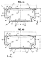
- FIG. 4a shows spacer profile 1 according to a third embodiment.
- the spacer profile 1 according to the third embodiment is formed in a so-called "W configuration".
- the sidewalls 16 each have a concave connecting portion 40 to the outer wall 14 when viewed from within the chamber 20. Since the reinforcing layers 22, 24 extend on the outside of the side walls 16, 18 as far as the outside of the outer wall 14, the reinforcing layers 22, 24 also have a corresponding concave connecting section 40.
- the concave connecting portion 40 leads to an extension of the reinforcing layers 22, 24 at the same first width b1 and first height h1 of the spacer profile 1.
- the flexural rigidity of the spacer profile 1 is further improved due to the changed structure. Due to the concave connecting portions 40, the bulge 21 in the outer wall 14 can be dispensed with. In bending, the region having the diffusion barrier layer 26 folds inwardly toward the chamber 20. The region comprising the diffusion barrier layer 26 lies on the neutral fiber of the spacer.
- the remaining spacer profile 1 corresponds to that in the FIG. 3a ) shown.
- the in the FIG. 4b ) fourth embodiment differs from that in the FIG. 4a ) shown in that the first distance a1 relative to in FIG. 4a ) illustrated embodiment is enlarged. As a result, the heat conduction can be reduced again.
- the fifth to twelfth embodiments described below each have in particular a diffusion-tight diffusion barrier 27, which consists of the first reinforcing layer 22, the diffusion barrier layer 26 and the second reinforcing layer 24 is formed. Further, in all the illustrated embodiments, the diffusion barrier layer 26, when bent about an axis parallel to the transverse direction X, lies on the neutral fiber of the spacer profile 1 FIG. 5 to 14 For simplicity, none of the optional notches 32 and bulges 21, 121 are shown.
- the extension portion 28 has a bend 29 of 90 ° according to the first and second embodiments and an adjoining portion (flange) extending in the transverse direction X from the outer edge of the corresponding side wall 16, 18 via a Length 11 extends inwards.
- the extension section 28 has no additional profiling in the form of a groove extending in the longitudinal direction Z, but runs in a straight line.
- a spacer profile 1 according to a sixth embodiment is shown in cross section in the XY plane.
- the sixth embodiment differs from the fifth embodiment in that the extension portions 28 are almost twice as long as in the first embodiment, with the extension length 11 in the transverse direction X remaining almost the same.
- the second bend 29 by 180 ° is formed with the distance 11 from the outside of the corresponding side wall 16, 18, so that the portion of the extension portion 28, which adjoins the second bend 29, also in the transverse direction X, but to the outside extends. This ensures that a much longer extension section is arranged in the inner wall 12 of the spacer profile 1, resulting in improved bending properties.
- this part of the material of the hollow profile body 10 is enclosed on three sides by the formed by the extension portions 28 profiles.
- This containment causes the encapsulated material to act as a substantially incompressible volume element during a buckling bending operation. This results in an improved bending behavior or stiffness behavior.
- a spacer profile 1 is described according to a seventh embodiment, wherein in the FIG. 7c ) and d) in a) or b) of a circle surrounded areas are shown enlarged.
- the extension portions 28 do not protrude into the inner wall 12, but are provided on the outer side of the inner wall 12.
- the extension portions 28 are in a very advantageous for the bending behavior position, but visible in the installed state for a consumer.
- FIG. 8a ) and b) are cross-sectional views of a spacer profile 1 according to an eighth embodiment.
- the eighth embodiment differs from the fifth embodiment in that the bend 29 is not a 90 ° bend but a 180 ° bend, so that the part of the extension portion 28 adjoining the bend 29 extends in the height direction Y.
- a three-sided enclosure of a portion of the material of the hollow profile body 10 is achieved, although only one bend 29 is present. This leads to improved bending behavior and stiffness behavior.
- FIG. 9a and b) are cross-sectional views of a spacer profile holder 1 according to a ninth embodiment.
- the ninth embodiment differs from the eighth embodiment only in that the radius of curvature of the extension portions 28 is smaller than in the eighth embodiment.
- FIG. 10a ) and b) are cross-sectional views of a spacer profile 1 according to a tenth embodiment.
- the tenth embodiment differs from the first to ninth embodiments in that the extension portions 28 first make a bend 29 inward by about 45 ° and then a bend 29 about 45 ° in the opposite direction and then a bend 29 of 180 ° ° with the corresponding three-sided inclusion of a part of the material of the hollow profile body 10.
- the length (in the cross section perpendicular to the longitudinal direction) of the extension portion 28, and thus the mass of the reinforcing layer additionally introduced in this portion or region of the spacer profile, can be increased significantly. This results in a reduced wrinkling during bending. Furthermore, slack is significantly reduced as the curved, angled and / or folded extension portion significantly contributes to the strength of the structural integrity of the bent spacer frame.
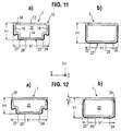
- FIG. 11a ) and b) show a spacer profile 1 according to an eleventh embodiment in a W and a U configuration.
- the spacer profile 1 of this embodiment has no extension portions 28.
- FIG. 12a ) and b) show a spacer profile 1 according to a twelfth embodiment.
- This spacer profile 1 differs from that in the FIG. 10a ) and b) shown tenth embodiment in that the 180 ° bend 29 and the adjoining part of the Verisrurigsabitess 28 are not present.
- FIG. 13 is a further alternative embodiment in a plan view, seen in the Y direction from below, shown.
- the reinforcing layer 22, 24 has recesses 35 which are separated by transverse webs 36.
- Each recess is formed centrally between the side walls 16, 18 and has the second width b2 in the transverse direction X.
- the height of the recesses in the longitudinal direction Z is given by a second distance a2 of the transverse webs 36 to each other.
- the transverse webs 36 themselves extend with a second length 12 in the longitudinal direction Z.
- the transverse webs 36 and the recesses 35 are preferably arranged regularly in the longitudinal direction Z.
- the reinforcement layer 22, 24 may also have a different thickness / thickness in the height direction Y in the region of the transverse webs 36.
- the diffusion barrier layer 26 is applied at least to the areas of the outer wall 14 not covered by the reinforcing layers 22, 24 between the transverse webs 36 and the reinforcing layer 22, 24.
- the diffusion barrier layer can be applied to the transverse webs 36 to simplify the production. In such an embodiment, the upper limit of the load in the transverse direction X, or the compressive / tensile force that can withstand the spacer profile in the transverse direction X, without being deformed or broken, is increased. Furthermore, it can be easily ensured that the diffusion barrier layer 26 lies in the neutral fiber.
- FIG. 14 shows another embodiment not having all of the claimed features in which the reinforcement layers 22, 24 are completely received in the sidewalls 16, 18 and partially in the outer wall 14.
- FIG. 17 shows in a) to d) the fifteenth to nineteenth embodiment.
- the diffusion barrier layer 266 is not formed of a metal material but of a plastic material.
- the plastic material is diffusion-tight.
- a diffusion-proof plastic material is, for example, an ethylene-vinyl alcohol copolymer, which is also referred to as EVOH.
- EVOH ethylene-vinyl alcohol copolymer
- Such an EVOH material preferably has a third specific thermal conductivity ⁇ 33 between 0.25 W / (mK) and 0.40 W / (mK).
- the diffusion barrier layer 266 of EVOH material may have a larger third thickness d33 compared to the metal material of the previous embodiments and at the same time allow high or higher thermal insulation. Again, however, so that an improvement of the thermal insulation is achieved compared to a continuous reinforcing layer, the product of the third specific thermal conductivity ⁇ 33 and the third thickness d33 smaller than the product of the first specific thermal conductivity ⁇ 1 and the first thickness d1 and less than be the product of the second specific thermal conductivity ⁇ 2 and the second thickness d2.
- the sold under the name “SoarnoL” EVOH material from NIPPON GOSHEI is used.
- This product is offered with different ethylene contents.
- “SoarnoL V” 25 mol% ethylene
- “SoarnoL DC” 32 mol% ethylene
- “SoarnoL ET” 38 mol% ethylene
- “SoarnoL AT” 44 mol% ethylene
- “SoarnoL H” 48 mol% ethylene
- the material sold under the product name "SoarnoL 29 mol%” or “SoarnoL DT” or “SoarnoL D” with 29 mol% of ethylene is used.
- the third thickness d33 of the diffusion barrier layer 266 of EVOH material is substantially larger than the third thickness d3 of the diffusion barrier layer 26 of metal material in the first to fourteenth embodiments. Due to the larger thickness d33, the diffusion barrier layer 266 is much more resistant (more stretch-resistant, more tear-resistant) than the very thin metal layer / foil used in the above embodiments.
- the spacer profile 1 such that the diffusion barrier layer 266 lies on the neutral fiber of the spacer profile 1 when the spacer profile 1 is bent.
- the bulges 21, 121 and notches 32 are optional features.
- the spacer profile 1 according to the first to fourteenth embodiments is also formed such that the diffusion barrier layer 266 of EVOH material lies in bending the spacer profile 1 in the neutral fiber.
- the diffusion barrier layers 266 in the fifteenth to nineteenth embodiments extend in the longitudinal direction Z in a uniform cross-sectional shape in a section X-Y perpendicular to the longitudinal direction Z over the entire length of the spacer profile and are arranged symmetrically to the plane of symmetry L.
- the diffusion barrier layer 266 extends in the transverse direction X with a third width b3 over the first distance a1 between the first reinforcing layer 22 and the second reinforcing layer 24.
- the diffusion barrier layer 266 has a third thickness d33 in this embodiment.
- the diffusion barrier layer 266 is connected to the outer wall 14 directly, for example by coextrusion, lamination or by means of adhesion promoter diffusion-tight.
- the diffusion barrier layer 266 and the outer wall 14 are materially connected.
- the diffusion barrier layer 266 is also at its edges in the transverse direction X with the first and second reinforcing layers, respectively 22, 24 diffusion-tight, for example by means of adhesion promoter or by welding diffusion-tight, preferably materially connected.
- a continuous diffusion barrier 27 is formed by the reinforcing layers 22, 24 and the diffusion barrier layer 266.
- the diffusion barrier layer 266 and the reinforcing layers 22, 24 provide a substantially continuous plane.
- the diffusion barrier layer 266 is formed in a "pedestal" manner or in a reverse “T” shape in a space between the reinforcing layers 22, 24 on the outer wall 14.
- the gap extends between the reinforcing layers 22, 24 and is bounded on both sides in the transverse direction X by the edges of the reinforcing layers 22, 24 facing each other in the transverse direction X on the outer wall.
- the intermediate space is bounded on one side by the outside of the outer wall 14 facing away from the inner wall 12.
- the diffusion barrier layer 266 has a first region 70 and a second region 71.
- the first region 70 corresponds to the diffusion barrier layer 266 of the sixteenth embodiment.
- the width of the first region 70 corresponds to the first distance a1 between the reinforcing layers 22, 24.
- a fourth thickness d4 of the first region 70 in the height direction Y preferably corresponds to the thickness d1, d2 of the reinforcing layers 22, 24.
- the second region 71 which extends over a third width b3, which is greater than the first distance a1 between the reinforcing layers 22, 24, is formed adjacent to the first region.
- the second region 71 is formed overlapping the reinforcing layers 22, 24 over a width (b3-a1) / 2, respectively.
- the second region 71 has a fifth thickness d5.
- the first region 70 and the second region 71 are integrally formed.
- the diffusion barrier layer 266 may be coextruded with the hollow profile body 10 and the reinforcing layers 22, 24 together. Alternatively, it can also after the application of the reinforcing layers 22, 24, for example by means of adhesion promoter or by Laminating with the reinforcing layers 22, 24 and / or the outer wall 14 are preferably connected diffusion-tight.
- the total height h4 of the spacer profile in this case is the sum of the first h1 of the hollow profile body 10 and the third thickness d33 of the diffusion barrier layer 266.
- FIG. 17c 5 shows a seventeenth embodiment which, like the sixteenth embodiment, has a diffusion barrier layer 266 having a first region 70 formed between the reinforcing layers 22, 24.
- a second region 71 is not formed on the side of the reinforcing layers 22, 24 facing away from the outer wall 14, but opposite, on the side of the first region 70 facing the outer wall 14.
- the diffusion barrier layer 266 therefore extends between the reinforcing layers 22, 24 and partially on the inner wall 14 facing side of the reinforcing layers 22, 24, between them and the outer wall 14.
- the widths in the transverse direction X and the thicknesses in the height direction Y of the first Area 70 and second area 71 preferably correspond to those of the sixteenth embodiment.
- the areas 72 overlapping with the reinforcing layers 22, 24 also have the dimensions of the sixteenth embodiment.
- the outer wall 14 has a reduced wall thickness (s1-d5) in the region in which the diffusion barrier layer 266 is formed.
- the second region 71 of the diffusion barrier layer 266 is preferably completely enclosed by the outer wall.
- the diffusion barrier layer 266 substantially coincides with the second region 71 of the seventeenth embodiment.
- the diffusion barrier layer 266 has a third thickness d33 in the height direction Y and a third width b3 in the transverse direction X.
- the third width b3 is larger than the first distance a1.
- the diffusion barrier layer 266 has a rectangular cross section as seen in the XY plane, and is completely surrounded by the outer wall 14.
- the outer wall 14 has Therefore, in the region between the reinforcing layers 22, 24 has a smaller wall thickness (s1-d33).
- the diffusion barrier layer 266 is arranged symmetrically with respect to the axis of symmetry L so as to be disposed across a width (b3-a1) / 2 between the reinforcing layers 22, 24 and the outer wall 14, respectively. overlaps with the reinforcing layers in the transverse direction X.
- the diffusion barrier layer 266 is not formed in the plane defined by the edge reinforcing layers 22, 24 in the transverse direction X (ignoring the bulge 21) but formed in the height direction Y in the direction of the inner wall 12 adjacent to this plane.
- the diffusion barrier layer 266 is formed with a rectangular cross section as seen in the XY plane.
- the diffusion barrier layer has a third thickness d33 in the height direction Y and a third width b3 in the transverse direction X.
- the third width b3 is greater than the first distance a1.
- the wall thickness s1 of the outer wall 14 between the reinforcing layers 22, 24 in the central region 25 on the side facing away from the inner wall 12 by the thickness d1 and d2 is greater.
- the outer wall 14 forms a continuous plane 73 with the reinforcing layers 22, 24 and intercepts the reinforcing layers 22, 24 at their edges in the transverse direction X.
- the diffusion barrier layer 266 is applied or formed symmetrically to the plane of symmetry L on this continuous plane 73.
- the diffusion barrier layer 266 abuts both the reinforcing layers 22, 24 and the outer wall 14 in the region between the reinforcing layers 22, 24.
- the in the FIGS. 17c), 17d ) and 17e ) shown diffusion barrier layers 266 can be coextruded either with the hollow profile body 10 or with the hollow profile body 10 and the reinforcing layers 22, 24 together.
- they prior to applying the reinforcing layers 22, 24 to the outer wall 14, they may be applied by primer, by lamination, by welding, etc. (see also first to fourteenth embodiments).
- they can also after the attachment of the reinforcing layers 22, 24, for example be attached by inserting and gluing.
- FIG. 18 shows a twentieth embodiment of the present invention.
- the entire hollow profile body 10 is formed of the diffusion-tight EVOH material.
- the diffusion barrier 27 always formed by the reinforcing layers 22, 24 and the diffusion barrier layer 26, 266 in the above embodiments is realized by the side walls 16, 18 and the outer wall 14 in this embodiment.
- the diffusion barrier layer is integrally formed with the outer wall 14 in this embodiment.
- only the side walls 16, 18 and the outer wall 14 or only the outer wall 14 may be formed of the EVOH material.
- the wall thickness of the respective walls made of the EVOH material may be up to 2 mm, but preferably corresponds to that of the first to fourteenth embodiments.
- the diffusion-tightness of EVOH material can be adversely affected by contact with water or water vapor, especially with thin EVOH material.
- EVOH material may tend to absorb water or water vapor. The absorption can also reduce the diffusion-tightness.
- a two-layer diffusion barrier layer has a first layer of EVOH material (first layer 74).
- the first layer of EVOH material is deposited on a carrier layer (second layer 75) which has a very low water permeability or is diffusion-tight with respect to water / water vapor.
- second layer 75 which has a very low water permeability or is diffusion-tight with respect to water / water vapor.
- the first layer of EVOH material is protected by the second layer from contact with water.
- Particularly preferred is an arrangement in which the first layer of the EVOH material is protected from contact with water / water vapor both by the second layer and by the outer wall 14 hollow profile body. In this particularly advantageous embodiment, the first layer is therefore arranged between the outer wall 14 and the second layer.
- Polyolefin more preferably PE and even more preferably PP may be used as the material for the carrier layer.
- FIG. 19 shows a section of a spacer profile of such a particularly advantageous twenty-first embodiment of the present invention.
- the detail shows only the outer wall 14 of the spacer profile 1 in the region in which the diffusion barrier layer between the reinforcing layers 22, 24 is arranged.
- the diffusion barrier layer 266 consists of a first layer 74 formed of a diffusion-tight EVOH material (as above, for example, "SoarnoL") and a second layer 75 of polyolefin, is formed, for example, PE or PP is formed.
- a diffusion-tight EVOH material as above, for example, "SoarnoL”
- a second layer 75 of polyolefin is formed, for example, PE or PP is formed.
- the diffusion barrier layer 266 of the first and second layers 74, 75 has substantially the shape of the diffusion barrier layer 266 according to the sixteenth embodiment, which in FIG. 17b ) is shown.
- the first layer 74 corresponding to the first region 70 of the sixteenth embodiment is formed between the reinforcing layers 22, 24.
- the second layer 75 is formed on the first layer 74 corresponding to the second region 71 of the sixteenth embodiment, and partially extends on its edges in the transverse direction X on the sides of the reinforcing layers 22, 24 remote from the outer wall 14.
- the first layer has a thickness d331 and the second layer has a thickness d332 in the height direction Y.
- the total thickness d333 preferably corresponds to the thickness d33 but may also be larger or smaller.
- the first layer 74 and the second layer 75 are preferably connected to one another by means of adhesion promoter 76 applied between the two layers and / or are preferably formed together by coextrusion.
- adhesion promoter 76 applied between the two layers and / or are preferably formed together by coextrusion.
- the diffusion barrier layer 266 according to the twenty-first embodiment may also have other shapes.
- it may correspond to the fifteenth to nineteenth Embodiment be formed.
- the diffusion barrier layers 266 shown in the fifteenth to nineteenth embodiments may also be made of a first EVOH layer and a second PP or PE layer, respectively.
- each of the first layer 74 of EVOH material is disposed between the second polyolefin layer 75 and the outer wall 14 such that it is protected from contact with water / water vapor.
- the first layer 74 and the second layer 75 may also be reversed. That is, the first layer 74 may be formed on the side of the second layer 75 facing away from the outer wall 14, and the second layer 75 may be applied directly on the outer wall 14.
- the first layer 74 of the EVOH material in this case is not protected from water or water vapor.
- a PP / PE layer may be applied to the diffusion barrier layer 266 of EVOH material between the reinforcement layers 22, 24 to protect the EVOH material diffusion barrier layer 266 from contact with water / water vapor.
- the twentieth embodiment shown may be modified by applying a layer of polyolefin (eg, PP or PE) on the outer wall 14 between the reinforcing layers 22, 24.
- a layer of polyolefin eg, PP or PE
- the walls of EVOH material would be protected from contact with water / water vapor, so that an optimal diffusion-tightness would be ensured.
- the reinforcing layers may be formed asymmetrically with respect to each other with respect to the plane of symmetry L.
- the first reinforcing layer may be different in thickness / thickness relative to the second reinforcing layer, or may be formed of different material.
- the first or second reinforcing layer may have an extension portion while the other may not have an extension portion.
- the reinforcing layers may also extend only on the sidewalls and the diffusion barrier layer may extend over the entire outer wall for joining the two reinforcing layers.
- the reinforcing layers may also optionally extend partially in the sidewalls or the outer wall, but are always connected to the outer wall with the diffusion barrier layer.
- the first or second reinforcing layer may extend over a larger portion on the outer wall than the respective other reinforcing layer. That the distance of the central region from the first side wall may be greater than the distance to the second side wall and vice versa.
- the central area does not necessarily have to be arranged centrally between the side walls. Due to the non-central arrangement of the central region, the heat conduction can be reduced by the spacer profile. In particular, the heat conduction is reduced when the central area is closer to the "warm", i. inner disc is arranged.
- the diffusion barrier layer may be formed overlapping the first and / or second reinforcing layer. That is, for example, the diffusion barrier layer 26 shown in the first to thirteenth embodiments, which is applied directly to the outer wall 14 after extrusion in the central region 25, may also be partially applied to the first and / or second reinforcing layers 22, 24.
- the diffusion barrier layer may therefore extend integrally at least partially on the first reinforcing layer and the second reinforcing layer and between both on the outer wall. However, according to the construction, the diffusion barrier layer extends only on the region directly on the outer wall, which is not covered by the first or second reinforcing layer. By an overlap, a particularly diffusion-tight formation of the connection between reinforcing layers 22, 24 and diffusion barrier layer 26 is formed.
- the side walls or areas thereof can also have regions which are designed so that a notch can be dispensed with. For example, this can be achieved by making the sidewalls or regions thereof thinner-walled than others.
- the extension sections can optionally also be omitted (see Fig. 11 ).
- the reinforcing layers can be applied directly to the hollow profile body, for example by means of adhesion promoters or adhesives, even after the extrusion of the hollow profile body.
- the area provided for the reinforcing layer and / or diffusion barrier layer may be formed on the hollow profile body such that no steps are present at the edges and transitions between them after the application of the reinforcing layers and / or the diffusion barrier layer. That is, the areas to which the reinforcing layers are applied, for example, are formed as recesses in the extrusion of the hollow profile body. Accordingly, the reinforcing layers and / or diffusion barrier layer are inserted in these recesses.
- the hollow profile body may also be trapezoidal, square, diamond-shaped or otherwise formed.
- the concave bulges may take other shapes, for example be doubly bulged, be asymmetrically bulged, etc.
- the spacer profile may also be formed such that the side walls do not represent the outermost in the transverse direction X walls to rest against the discs.
- Such a configuration could, for example, be designed as follows: the spacer profile has a wider inner wall compared to the outer wall.
- the side walls are not connected to the edges of the inner wall in the transverse direction X but are slightly offset in the transverse direction X inwards.
- the outer wall connected to the side walls, the side walls and the inner wall form the chamber.
- the reinforcing layers are in such an embodiment wholly or partly formed in or on the additional outer walls and the side walls and the inner wall.
- the diffusion barrier layer connects the reinforcing layers diffusion-tight with each other.
- the wall thicknesses s1, s2 of the side walls 22, 24 and / or the outer wall 26 may also be formed differently from each other.
- the openings 34 may also be asymmetrical to the symmetry line L, as in FIG Fig. 15 shown to be formed only centrally or only on one side with respect to the transverse direction X.
- the openings may be arranged regularly or irregularly in the longitudinal direction Z.
- the openings may be formed in one or more rows with respect to the transverse direction X.
- a further reinforcing layer of a metal material In or on the inner wall may be at least partially provided a further reinforcing layer of a metal material.
- the extension portions 28 may be bent, angled, etc. in any shape, or may be asymmetrical with each other.
- the chamber can also be divided by intermediate walls into several chambers.
- the cross section of the reinforcing layers need not necessarily be constant, but may also have a profiled shape, so that it is even better connected to the hollow profile body. In particular, for example, knobs or grooves may be provided.
- the notches 32 and bulges 21, 121 shown in the first to fourth embodiments are optional features that may be omitted depending on the configuration of the hollow profile body.
- the first height h1 of the hollow profile body 10 in the height direction Y is preferably between 10 mm and 5 mm, more preferably between 8 mm and 6 mm, e.g. 6.85mm, 7.5mm and 8mm.
- the second height h2 of the camber 21 in the height direction Y is preferably between 1 mm and 0.05 mm, more preferably between 1 mm and 0.1 mm, such as e.g. 0.5mm, 0.8mm and 1mm.
- the third height h3 of the camber 121 in the height direction Y is preferably between 1.5 mm and 0.09 mm, more preferably between 0.5 mm and 0.05 mm, still more preferably between 0.3 mm and 0.07 mm, such as eg 0.1 mm, 0.12 mm, and 0.15 mm.
- the first width b1 of the hollow profile body 10 in the transverse direction X is preferably between 40 and 6 mm, more preferably between 20 mm and 6 mm, and even more preferably between 16 mm and 8 mm, e.g. 8 mm, 12 mm and 15,45 mm.
- the first distance a1 which corresponds to the second width b2, in the transverse direction X is preferably between 15 mm and 2 mm, more preferably between 8 mm and 5 mm, e.g. 5 mm, 6 mm and 8 mm.
- the third width b3 of the diffusion barrier layer 266 is preferably between 35 mm and 2 mm, more preferably between 20 mm and 2 mm, even more preferably between 12 and 5 such as 6 mm, 7 mm and 9 mm.
- the first thickness d1 of the first reinforcing layer 22 of metal material is preferably between 0.5 mm and 0.01 mm, more preferably between 0.2 mm and 0.01 mm, e.g. 0.1 mm, 0.05 mm and 0.01 mm.
- the second thickness d2 of the second reinforcing layer 24, 124 preferably corresponds to the first thickness d1.
- the third thickness d3 of the diffusion barrier layer 26 of metal material is preferably between 0.09 mm and 1 nm, more preferably between 0.02 mm and 5 nm, and even more preferably between 0.01 mm and 10 nm, e.g. 0.01 mm, 0.001 mm and 10 nm.
- the third thickness d33 of the EVOH diffusion barrier layer 266 is preferably between 0.01 mm and 2 mm, more preferably between 0.05 mm and 0.8 mm, and more preferably between 0.1 mm and 0.3 mm, such as eg 0.1 mm, 0.2 mm and 0.3 mm.
- the thickness d331 of the second layer 75 of PP or PE is preferably between 1.2 mm and 0.1 mm, more preferably between 1.00 mm and 0.5 mm, e.g. 0.5 mm, 0.6 mm and 0.7 mm.
- the thickness d332 of the first layer 74 of EVOH material is preferably between 0.01 mm and 2 mm, more preferably between 0.05 mm and 0.8 mm, and more preferably between 0.1 mm and 0.3 mm, such as eg 0.1 mm, 0.2 mm and 0.3 mm.
- the first length 11 of the extension portions in the transverse direction X is preferably 0.05 b1 ⁇ 11 ⁇ 0.8 b1, more preferably 0.1 b1 ⁇ 11 ⁇ 0.5 b1 and even more preferably 0.1 b1 ⁇ 11 ⁇ 0.2 b1 mm.
- the first wall thickness s1 of the sidewalls 16, 18 and the outer wall 14 is preferably between 1.2 mm and 0.2 mm, more preferably between 1.00 mm and 0.5 mm, e.g. 0.5 mm, 0.6 mm and 0.7 mm.
- the second wall thickness s2 of the inner wall 12 is preferably between 1.5 mm and 0.5 mm, such as 0.7 mm, 0.8 mm, 0.9 mm and 1 mm.
- the first length 11 in the transverse direction X is smaller than b1 / 2.
Landscapes
- Engineering & Computer Science (AREA)
- Civil Engineering (AREA)
- Structural Engineering (AREA)
- Architecture (AREA)
- Securing Of Glass Panes Or The Like (AREA)
- Joining Of Glass To Other Materials (AREA)
- Wing Frames And Configurations (AREA)
Description
Die vorliegende Erfindung betrifft ein Abstandshalterprofil zur Verwendung in Isolierscheibeneinheiten mit einem solchen Abstandshalterprofil und eine Isolierscheibeneinheit mit einem solchen Abstandshalterprofil.The present invention relates to a spacer profile for use in insulating disk units having such a spacer profile and an insulating disk unit having such a spacer profile.
Isolierscheibeneinheiten mit wenigstens zwei Scheiben 151, 152, die in der Isolierscheibeneinheit in einem Abstand voneinander gehalten werden, sind bekannt (siehe
Der Scheibenzwischenraum 153 wird bevorzugt mit einem isolierenden Inertgas, wie beispielsweise Argon, Krypton, Xenon, etc. gefüllt. Das Füllgas soll auch über einen langen Zeitraum nicht aus dem Scheibenzwischenraum 153 entweichen können. Ebenso soll auch die Umgebungsluft, bzw. Bestandteile von ihr, wie beispielsweise Stickstoff, Sauerstoff, Wasser, etc., nicht in den Scheibenzwischenraum 153 eindringen können. Aus diesem Grund muss das Abstandshalterprofil 100 derart ausgebildet sein, dass eine Diffusion zwischen dem Scheibeninnenraum 153 und der Umgebung verhindert wird. Abstandshalterprofile weisen daher eine Diffusionssperre 157 auf, die eine Diffusion des Füllgases aus dem Scheibenzwischenraum 153 in die Umgebung durch das Abstandshalterprofil 100 verhindert.The
Weiterhin spielt zur Erzielung einer geringen Wärmeleitung bei diesen Isolierscheibeneinheiten insbesondere die Wärmeübertragung des Randverbundes, d.h. des Verbundes des Randes der Isolierscheibeneinheit, der Scheiben 151, 152 und des Abstandshalterrahmens 150 eine sehr große Rolle. Isolierscheibeneinheiten, die eine hohe Wärmedämmung im Randverbund sicherstellen, erfüllen die sogenannte "warm edge"-Bedingung entsprechend der Bedeutung des Begriffs in der Technik. Die Abstandshalterprofile 100 sollen also eine gute Wärmedämmung aufweisen.Furthermore, to achieve a low heat conduction in these Isolierscheibeneinheiten in particular the heat transfer of the edge bond, ie the composite of the edge of the Isolierscheibeneinheit, the
Der Abstandshalterrahmen 150 wird bevorzugt aus einem einstückigen Abstandshalterprofil 100 gebogen. Zum Schließen des Rahmens 150 werden die beiden Enden des Abstandshalterprofils 100 mittels eines Verbinders verbunden. Wird der Abstandshalterrahmen 150 aus mehreren Abstandshalterprofilstücken 100 zusammengesetzt, sind auch mehrere Verbinder notwendig. Sowohl bezüglich der Herstellkosten als auch bezüglich der Dämmeigenschaften ist es bevorzugt, nur eine Verbindungsstelle vorzusehen.The
Die Biegung des Rahmens 150 aus dem Abstandshalterprofil 100 erfolgt beispielsweise durch Kaltbiegen (bei einer Raumtemperatur von ungefähr 20°C). Dabei tritt das Problem der Faltenbildung an den Biegungen auf.The bending of the
Das Abstandshalterprofil sollte mit möglichst geringer Faltenbildung zu biegen sein und gleichzeitig auch eine hohe Festigkeit und Biegesteifigkeit aufweisen.The spacer profile should be bend with the least possible wrinkling and at the same time also have a high strength and flexural rigidity.
Aus der
Weiter sind Abstandshalter bekannt, die eine vergleichsweise dünne durchgehende Verstärkungsschicht aus Metallmaterial auf dem Profilkörper aus Kunststoff aufweisen. Solche Abstandshalter verlieren beim Biegen um 90° Ihre Diffusionsdichtigkeit und weisen vergleichsweise dicke Kunststoffprofilwände auf, damit sie nicht zu stark durchhängen.Next spacers are known which have a comparatively thin continuous reinforcing layer of metal material on the profile body made of plastic. Such spacers lose their bending resistance by 90 ° in their diffusion-tightness and have comparatively thick plastic profile walls, so they do not sag too much.
Aus der
Eine Aufgabe der Erfindung ist es, ein verbessertes Abstandshalterprofil anzugeben, bei dem insbesondere die Wärmedämmung bei guter Festigkeit bzw. Biegesteifigkeit und guter Faltenbildungseigenschaften beim Biegen verbessert ist. Eine Isolierscheibeneinheit mit solchen Abstandshalterprofilen ist ein anderes Ziel der Erfindung.An object of the invention is to provide an improved spacer profile, in which in particular the thermal insulation is improved with good strength or bending stiffness and good folding properties during bending. An insulating disk unit having such spacer profiles is another object of the invention.
Diese Aufgabe wird gelöst durch ein Abstandshalterprofil nach Anspruch 1, bzw. eine Isolierscheibeneinheit nach Anspruch 15.This object is achieved by a spacer profile according to
Weiterbildungen der Erfindung sind in den abhängigen Ansprüchen angegeben.Further developments of the invention are specified in the dependent claims.
Die Diffusionsdichtigkeit wird einerseits durch eine Diffusionssperre, die aus den zwei Verstärkungsschichten und der Diffusionssperrschicht ausgebildet ist und beim Biegen des Abstandshalterprofils in der neutralen Faser liegt, sichergestellt. Andererseits kann auch der Hohlprofilkörper mindestens teilweise aus einem diffusionsdichten Kunststoffmaterial, beispielsweise einem EVOH-Material hergestellt sein, dass die Diffusionsdichtigkeit sicherstellt. Auch in diesem Fall ist zwischen den Verstärkungsschichten eine Diffusionssperrschicht, nämlich der zwischen den Verstärkungsschichten befindliche Teil der Außenwand, ausgebildet. Durch die Diffusionssperrschicht wird wesentlich weniger Wärme übertragen als durch die Verstärkungsschichten. Das Abstandshalterprofil mit den zwei voneinander getrennten Verstärkungsschichten, die in einem zentralen Bereich mittels einer Diffusionssperrschicht miteinander verbunden sind, weist bei gleichbleibender Diffusionsdichtigkeit eine wesentlich niedrigere Wärmeleitfähigkeit auf, als ein vergleichbares konventionelles Abstandshalterprofil. Gleichzeitig wird das Abstandshalterprofil steifer und fester. Des Weiteren kann Material eingespart, wodurch die Herstellkosten und Gewicht gesenkt werden können. Durch eine geeignete Ausbildung der Geometrie des Hohlprofilkörpers und der Verstärkungsschichten liegt die Diffusionssperrschicht beim Biegen des Abstandshalters annähernd auf der neutralen Faser (der beim Biegen keine Dehnung oder Stauchung erfahrenden Zone des Materials) des Abstandshalterprofils. Daher wirken beim Biegen im Wesentlichen keine Zugspannungen auf die Diffusionssperrschicht. Aus diesem Grund kann eine Diffusionssperrschicht verwendet werden, die keine oder nur geringe Zugkräfte aufnehmen muss. Zudem kann die Diffusionssperrschicht einfach auf das Abstandshalterprofil aufgebracht werden.The diffusion-tightness is ensured on the one hand by a diffusion barrier, which is formed from the two reinforcing layers and the diffusion barrier layer and lies in bending the spacer profile in the neutral fiber. On the other hand, the hollow profile body may be at least partially made of a diffusion-tight plastic material, such as an EVOH material that ensures the diffusion-tightness. Also in this case, between the reinforcing layers, a diffusion barrier layer, namely the part of the outer wall located between the reinforcing layers, is formed. The diffusion barrier layer transmits much less heat than the reinforcement layers. The spacer profile with the two mutually separated reinforcing layers, which are interconnected in a central region by means of a diffusion barrier layer, has a substantially lower thermal conductivity, while maintaining the same diffusion-tightness, than a comparable conventional spacer profile. At the same time, the spacer profile becomes stiffer and stronger. Furthermore, material can be saved, whereby the manufacturing costs and weight can be reduced. By proper formation of the geometry of the hollow profile body and the reinforcing layers, the diffusion barrier layer, as the spacer is bent, lies approximately on the neutral fiber (the zone of material which does not strain or buckle upon bending) of the spacer profile. Therefore, in bending, substantially no tensile stresses act on the diffusion barrier layer. For this reason, a diffusion barrier layer can be used, which must absorb little or no tensile forces. In addition, the diffusion barrier layer can be easily applied to the spacer profile.
Weitere Merkmale und Zweckmäßigkeiten ergeben sich aus der Beschreibung von beispielhaften Ausführungsfonnen anhand der Figuren. Von den Figuren zeigen:
- FIG. 1
- in a) und b) je eine perspektivische Querschnittsansicht einer zusammengebauten Isolierscheibeneinheit mit dazwischen angeordnetem Abstandshalterprofil, Klebematerial und Dichtmaterial,
- FIG. 2
- eine schematische Seitenansicht, teilweise aufgeschnitten, eines aus einem Abstandshalterprofil gebogenen Abstandshalterrahmens im idealen Zustand,
- FIG. 3
- eine Querschnittsansicht eines Abstandshalterprofils, in a) nach einer ersten Ausführungsform, in einer U-Konfiguration und mit einer schmalen Diffusionssperrschicht, und in b) nach einer zweiten Ausführungsform, in einer U-Konfiguration und mit einer breiten Diffusionssperrschicht,
- FIG. 4
- eine Querschnittsansicht eines Abstandshalterprofils, in a) nach einer dritten Ausführungsform, in einer W-Konfiguration und mit einer schmalen Diffusionssperrschicht, und in b) nach einer vierten Ausführungsform, in einer W-Konfiguration und mit einer breiten Diffusionssperrschicht,
- FIG. 5
- eine Querschnittsansicht eines Abstandshalterprofils nach einer fünften Ausführungsform, in a) in einer W-Konfiguration und in b) in einer U-Konfiguration,
- FIG. 6
- eine Querschnittsansicht eines Abstandshalterprofils nach einer sechsten Ausführungsform, in a) in einer W-Konfiguration und in b) in einer U-Konfiguration,
- FIG. 7
- eine Querschnittsansicht eines Abstandshalterprofils nach einer siebten Ausführungsform, in a) in einer W-Konfiguration und in b) in einer U-Konfiguration, in c) eine vergrößerte Ansicht des in a) von einem Kreis umgebenen Abschnitts und in d) eine vergrößerte Ansicht des in b) von einem Kreis umgebenen Abschnitts,
- FIG. 8
- eine Querschnittsansicht eines Abstandshalterprofils nach einer achten Ausführungsform, in a) in einer W-Konfiguration und in b) in einer U-Konfiguration,
- FIG. 9
- eine Querschnittsansicht eines Abstandshalterprofils nach einer neunten Ausführungsform, in a) in einer W-Konfiguration und in b) in einer U-Konfiguration,
- FIG. 10
- eine Querschnittsansicht eines Abstandshalterprofils nach einer zehnten Ausführungsform, in a) in einer W-Konfiguration und in b) in einer U-Konfiguration,
- FIG. 11
- eine Querschnittsansicht eines Abstandshalterprofils nach einer elften Ausführungsform, in a) in einer W-Konfiguration und in b) in einer U-Konfiguration,
- FIG. 12
- eine Querschnittsansicht eines Abstandshalterprofils nach einer zwölften Ausführungsform, in a) in einer W-Konfiguration und in b) in einer U-Konfiguration,
- FIG. 13
- eine Aufsicht auf die Außenwand eines Abstandshalterprofils nach einer dreizehnten Ausführungsform, und
- FIG. 14
- eine Querschnittsansicht eines Abstandshalterprofils nach einer vierzehnten Ausführungsform,
- FIG. 15
- eine Querschnittsansicht des Abstandshalterprofils nach der ersten Ausführungsform nach einem Biegevorgang,
- FIG. 16
- in a) und b) je eine perspektivische Querschnittsansicht einer zusammengebauten Isolierscheibeneinheit mit dazwischen angeordnetem Abstandshalterprofil, Klebematerial und Dichtmaterial, wie sie im Stand der Technik bekannt ist,
- FIG. 17
- in a) bis e) jeweils eine Querschnittsansicht eines Abstandshalterprofils nach einer fünfzehnten bis neunzehnten Ausführungsform,
- FIG. 18
- eine Querschnittsansicht eines Abstandshalterprofils nach einer zwanzigsten Ausführungsform, und
- FIG. 19
- einen Ausschnitt einer Querschnittsansicht eines Abstandshalterprofils nach einer einundzwanzigsten Ausführungsform.
- FIG. 1
- in a) and b) each show a perspective cross-sectional view of an assembled Isolierscheibeneinheit with interposed spacer profile, adhesive material and sealing material,
- FIG. 2
- a schematic side view, partially cut away, of a spacer profile bent spacer frame in the ideal state,
- FIG. 3
- a cross-sectional view of a spacer profile, in a) according to a first embodiment, in a U-configuration and with a narrow diffusion barrier layer, and in b) according to a second embodiment, in a U-configuration and with a wide diffusion barrier layer,
- FIG. 4
- a cross-sectional view of a spacer profile, in a) according to a third embodiment, in a W configuration and with a narrow diffusion barrier layer, and in b) according to a fourth embodiment, in a W configuration and with a wide diffusion barrier layer,
- FIG. 5
- a cross-sectional view of a spacer profile according to a fifth embodiment, in a) in a W configuration and in b) in a U-configuration,
- FIG. 6
- a cross-sectional view of a spacer profile according to a sixth embodiment, in a) in a W configuration and in b) in a U-configuration,
- FIG. 7
- a cross-sectional view of a spacer profile according to a seventh embodiment, in a) in a W configuration and b) in a U-configuration, in c) an enlarged view of the in a) surrounded by a circle portion and in d) an enlarged view of in b) section surrounded by a circle,
- FIG. 8th
- a cross-sectional view of a spacer profile according to an eighth embodiment, in a) in a W configuration and in b) in a U-configuration,
- FIG. 9
- a cross-sectional view of a spacer profile according to a ninth embodiment, in a) in a W configuration and b) in a U-configuration,
- FIG. 10
- a cross-sectional view of a spacer profile according to a tenth embodiment, in a) in a W configuration and in b) in a U-configuration,
- FIG. 11
- a cross-sectional view of a spacer profile according to an eleventh embodiment, in a) in a W configuration and in b) in a U-configuration,
- FIG. 12
- a cross-sectional view of a spacer profile according to a twelfth embodiment, in a) in a W configuration and in b) in a U-configuration,
- FIG. 13
- a plan view of the outer wall of a spacer profile according to a thirteenth embodiment, and
- FIG. 14
- a cross-sectional view of a spacer profile according to a fourteenth embodiment,
- FIG. 15
- a cross-sectional view of the spacer profile according to the first embodiment after a bending operation,
- FIG. 16
- in a) and b) each show a perspective cross-sectional view of an assembled Isolierscheibeneinheit with interposed spacer profile, adhesive material and sealing material, as is known in the art,
- FIG. 17
- in a) to e) are each a cross-sectional view of a spacer profile according to a fifteenth to nineteenth embodiment,
- FIG. 18
- a cross-sectional view of a spacer profile according to a twentieth embodiment, and
- FIG. 19
- a section of a cross-sectional view of a spacer profile according to a twenty-first embodiment.
Nachfolgend werden Ausführungsformen unter Bezugnahme auf die
Im Weiteren wird ein Abstandshalterprofil 1 nach einer ersten Ausführungsform unter Bezugnahme auf
Das Abstandshalterprofil 1 weist einen Hohlprofilkörper 10 aus einem Kunststoffmaterial auf, der sich in der Längsrichtung Z mit gleichbleibender Querschnittsform erstreckt und eine erste Breite b1 in der Querrichtung X und eine erste Höhe h1 in der Höhenrichtung Y aufweist. Der Hohlprofilkörper 10 weist in seiner Höhenrichtung Y eine Innenwand 12 und auf der der Innenwand 12 entgegengesetzten Seite in der Höhenrichtung Y eine Außenwand 14 auf. Die in der Querrichtung X äußeren Ränder der Innenwand 12 und der Außenwand 14 sind jeweils durch eine Seitenwand 16, 18, die im wesentlichen parallel zu der Höhenrichtung Y verläuft, miteinander verbunden. Die erste Seitenwand 16 liegt in Querrichtung X gegenüber der zweiten Seitenwand 18. Die Symmetrieebene L verläuft im Wesentlichen parallel zu den Seitenwänden 16, 18 und ist zentral zwischen ihnen angeordnet. Durch die Innenwand 12, die erste Seitenwand 16, die Außenwand 14 und die zweite Seitenwand 18, die miteinander verbunden sind, wird eine Kammer 20 gebildet bzw. begrenzt.The
Die erste Seitenwand 16, die zweite Seitenwand 18 und die Außenwand 14 weisen jeweils eine erste Wandstärke s1 auf. Die Innenwand 12 weist eine zweite Wandstärke s2 auf.The
Die Übergange bzw. Verbindungsabschnitte der Seitenwände 16, 18 zu der Außenwand 14 sind entsprechend der ersten Ausführungsform in der Querschnittsansicht jeweils gerundet, hier im Wesentlichen in Form eines Viertelkreises ausgebildet. Durch die zwei Seitenwände 16, 18 und die Außenwand 14 wird daher eine U-Form (U-Konfiguration) geschaffen, auf die die Innenwand 12 als Deckel aufgesetzt ist. Die Übergange bzw. Verbindungsabschnitte zwischen den Seitenwänden 16, 18 und der Innenwand 12 sind daher im Querschnitt zur Längsrichtung Z im Wesentlichen rechtwinklig, mit gerundetem Verbindungsabschnitt auf der der Kammer 20 zugewandten Seite, ausgebildet. Der Hohlprofilkörper 10 wird bevorzugt integral durch Extrusion hergestellt.The transitions or connecting portions of the
Die Außenwand 14 ist in dieser Ausführungsform bezüglich der Kammer 20 leicht konkav ausgebildet. D.h. die Außenwand 14 ist in Richtung des Innenraums der Kammer 20 in der Höhenrichtung Y zur Ausbildung einer Wölbung 21 gewölbt. Die Außenwand 14 ist in der Mitte bezüglich ihrer Ränder in der Querrichtung X, d.h. im Bereich der Symmetrieebene L, um eine zweite Höhe h2 nach innen in Richtung der Kammer 20 gewölbt.The
Auch die Innen wand 12 ist in dieser Ausführungsform bezüglich der Kammer 20 leicht konkav ausgebildet. D.h. die Innenwand 12 ist in Richtung des Innenraums der Kammer 20 in der Höhenrichtung Y zur Ausbildung einer Wölbung 121 gewölbt. Die Innenwand 12 ist in der Mitte bezüglich ihrer Ränder in der Querrichtung X, d.h. im Bereich der Symmetrieebene L, um eine dritte Höhe h3 nach innen in Richtung der Kammer 20 gewölbt.Also, the
Bevorzugt werden die Wölbungen 21 bereits bei der Extrusion im Kunststoff ausgebildet. Sie können aber auch direkt nach der Extrusion bzw. in einem nachträglichen Rollumformvorgang ausgebildet werden.Preferably, the
Direkt auf dem Hohlprofilkörper 10 erstrecken sich in dieser Ausführungsform jeweils auf einem Großteil der der Kammer 20 abgewandten Außenflächen der Seitenwände 16,18 und einem Teil der der Kammer abgewandten Außenseite der Außenwand 14 zwei Verstärkungsschichten 22, 24. Eine erste Verstärkungsschicht 22 erstreckt sich einstückig und durchgängig in der Längsrichtung Z mit gleichbleibendem Querschnitt direkt auf der (der Kammer abgewandten) Außenseite der ersten Seitenwand 16 von knapp unterhalb der Innenwand 12 zu dem und direkt auf dem der ersten Seitenwand 16 zugewandten Teil der (der Kammer abgewandten) Außenseite der Außenwand 14. Eine zweite Verstärkungsschicht 24 erstreckt sich einstückig und durchgängig in der Längsrichtung Z mit gleichbleibendem Querschnitt direkt auf der (der Kammer abgewandten) Außenseite der zweiten Seitenwand 18 von knapp unterhalb der Innenwand 12 zu dem und direkt auf dem der zweiten Seitenwand 18 zugewandten Teil der (der Kammer abgewandten) Außenseite der Außenwand 14. Die erste Verstärkungsschicht 22 ist aus einem ersten diffusionsdichten Metallmaterial mit einer ersten spezifischen Wärmeleitfähigkeit λ1 ausgebildet und die zweite Verstärkungsschicht 24 ist aus einem zweiten diffusionsdichten Metallmaterial mit einer zweiten spezifischen Wärmeleitfähigkeit λ2 ausgebildet.In this embodiment, directly on the
Soweit hier der Begriff "Diffusionsdichtigkeit" bzw. "diffusionsdicht" bezüglich des Abstandshalterprofils oder der das Abstandshalterprofil bildenden Materialien verwendet wird, sind in der folgenden Beschreibung bevorzugt sowohl Dampfdiffusionsdichtigkeit als auch Gasdiffusionsdichtigkeit für die in Rede stehenden Gase (beispielsweise Stickstoff, Sauerstoff, Wasser, etc., insbesondere Argon) gemeint. Gas- bzw. dampfdiffusionsdicht sind die verwendeten Materialien dann, wenn bevorzugt nicht mehr als 1 % der Gase im Scheibenzwischenraum 153 innerhalb eines Jahres entweichen kann. Diffusionsdicht ist auch gleichzusetzen mit diffusionsarm in dem Sinne, dass die entsprechende Prüfnorm EN 1279 Teil 2 + 3 bevorzugt erfüllt wird. D.h. das fertige Abstandshalterprofil erfüllt bevorzugt die Prüfnorm EN 1279 Teil 2+3.As far as the term "diffusion-tightness" or "diffusion-tight" is used herein with respect to the spacer profile or the spacer profile forming materials, in the following description are preferred both vapor diffusion tightness and gas diffusion tightness for the gases in question (for example, nitrogen, oxygen, Water, etc., especially argon). Gas or vapor diffusion-tight are the materials used, if preferably not more than 1% of the gases in the space between the
Die erste und die zweite Verstärkungsschicht 22, 24 berühren sich nicht. Die Verstärkungsschichten 22, 24 sind derart ausgebildet und angeordnet, dass sie bezüglich der Querrichtung X mit einem ersten Abstand a1 voneinander beabstandet sind. D.h. zwischen den Verstärkungsschichten 22, 24 bleibt auf der Außenseite der Außenwand 14 ein bezüglich der Querrichtung X zentraler Bereich 25, der sich in der Querrichtung X über den ersten Abstand a1 erstreckt, frei. Der zentrale Bereich 25 weist in dieser Ausführungsform eine zweite Breite b2 in der Querrichtung X auf, die dem ersten Abstand a1 entspricht. In oder auf diesem zentralen Bereich 25 ist keine Verstärkungsschicht ausgebildet bzw. angeordnet.The first and second reinforcing
Die Verstärkungsschichten 22, 24 erstrecken sich in dieser Ausführungsform symmetrisch bezüglich der Symmetrieebene L, so dass die erste Verstärkungsschicht 22 und die zweite Verstärkungsschicht 24 jeweils einen Abstand al/2 zu der Symmetrieebene L aufweisen. Die Verstärkungsschichten 22, 24 sind stoffschlüssig direkt mit den entsprechenden Wänden verbunden. Soweit hier der Begriff "stoffschlüssig direkt verbunden" oder "verbunden" verwendet wird, ist in der folgenden Beschreibung eine direkte Verbindung ohne weitere Zwischenschichten gemeint. Konkret bedeutet dies in der vorliegenden Ausführungsform, dass der Hohlprofilkörper 10 und die Verstärkungsschichten 22, 24 beispielsweise durch Koextrudieren des Hohlprofilkörpers 10 zusammen mit den Verstärkungsschichten 22, 24 und/oder gegebenenfalls unter Verwendung von Haftvermittlern dauerhaft miteinander verbunden sind und keine weiteren Schichten zwischen den Verstärkungsschichten 22, 24 und dem Hohlprofilkörper 10 ausgebildet sind.The reinforcing layers 22, 24 extend in this embodiment symmetrically with respect to the plane of symmetry L, so that the first reinforcing
Die erste Verstärkungsschicht 22 weist eine konstante erste Dicke d1 auf. Die zweite Verstärkungsschicht 24 weist eine konstante zweite Dicke d2 auf. Die erste Dicke d1 und die zweite Dicke d2 sind bei der vorliegenden Ausführungsform gleich. Da die Verstärkungsschichten 22, 24 jeweils auf der Außenseite der Außenwand 14 ausgebildet sind, erhöht sich in dieser Ausführungsform die Höhe des Hohlprofilkörpers 10 in der Höhenrichtung Y um den Betrag der Dicke d1 bzw. d2, so dass das Abstandshalterprofil 1 eine Gesamthöhe h4=h1+d1 aufweist. Die erste Breite b1 ändert sich nicht, da der Hohlprofilkörper 10 in dieser Ausführungsform an den Rändern in der Querrichtung X derart ausgebildet ist, dass die Verstärkungsschichten 22, 24 die erste Breite b1 nicht vergrößern. D.h., der Bereich der Seitenwände 16, 18, auf dem keine Verstärkungsschichten 22, 24 ausgebildet sind, ist entsprechend breiter ausgebildet.The first reinforcing
Die Verstärkungsschichten 22, 24 weisen bei der ersten Ausführungsform an ihren der Außenwand 14 in der Höhenrichtung Y entgegengesetzten Endbereichen profilierte Verlängerungsabschnitte 28 auf, die sich in der Längsrichtung Z erstrecken. Die Verlängerungsabschnitte 28 verlängern die Verstärkungsschichten 22, 24 in der Höhenrichtung Y von knapp unterhalb der Innenwand 12. Der Begriff "profiliert" bedeutet in diesem Zusammenhang, dass der Verlängerungsabschnitt 28 nicht ausschließlich eine lineare Verlängerung der jeweiligen Verstärkungsschicht 22, 24 in der Höhenrichtung Y ist, sondern dass in der zweidimensionalen Darstellung des Querschnitts in der X-Y-Ebene, ein zweidimensionales Profil ausgebildet ist, das z.B. eine oder mehrere Biegungen 29 des Verlängerungsabschnitts 28 aufweist.The reinforcing layers 22, 24 in the first embodiment have, at their end regions opposite to the
Bei dieser Ausführungsform weisen die Verlängerungsabschnitte 28 auf der Höhe der Innenwand 12 eine 90° Biegung 29 in Richtung der Symmetrieebene L in die Innenwand 12 auf. D.h. der Verlängerungsabschnitt 28 ragt in die Innenwand 12 hinein. Er weist weiter in der zweidimensionalen Darstellung des Querschnitts in der X-Y-Ebene eine Nut 30 auf. Der Verlängerungsabschnitt 28 ragt mit einer ersten Länge 11 in der Querrichtung X von der Außenseite der entsprechenden Seitenwand 16, 18 des Hohlprofilkörpers 10 in die Innenwand 12 ein.In this embodiment, the
Die Verlängerungsabschnitte 28 dienen einem verbesserten Biegeverhalten und einer verbesserten Haftung der Verstärkungsschichten 22, 24 auf, bzw. in dem Hohlprofilkörper 10. Es ist bevorzugt, wenn die Verlängerungsabschnitte 28 möglichst nahe an der der Kammer 20 abgewandten Außenseite der Innenwand 12 (möglichst nahe am Scheibenzwischenraum 53), aber bedeckt von dem Material der Innenwand 12 angeordnet sind. Die Verlängerungsabschnitte 28 sind jeweils in einem-Aufnahmebereich 31 aufgenommen. Ein solcher Aufnahmebereich 31 wird durch die Innenwand 12 und/oder Seitenwand 16, 18 ausgebildet und erstreckt sich von der Außenseite der Innenwand 12 in derselben und ggfs. der entsprechenden Seitenwand 16, 18 über eine Höhe in der Höhenrichtung Y, die kleiner als 0,4 h1 ist, bevorzugter kleiner als 0,2 h1 und noch bevorzugter weniger als 0,1 h1 ist. Die angegebene Höhe der Aufnahmebereiche 31 definiert auch den Anfang der Verlängerungsabschnitte 28. In der Querrichtung X weisen die Aufnahmebereiche 31 wenigstens die Dicke s 1 der Seitenwände 16, 18 auf. Bevorzugt erstrecken sich die Aufnahmebereiche von der der Kammer abgewandten Außenfläche der Seitenwände 16, 18 über eine Breite < 1,5 11, bevorzugter über eine Breite < 1,211 und noch bevorzugter über eine Breite von 1,1 11 in der Querrichtung X.The
Optional können die Innenwand 12 und/oder die Seitenwände 16, 18 im Bereich der Aufnahmebereiche 31 eine erhöhte Wandstärke aufweisen. Dies ist beispielhaft in den
Die Masse des jeweiligen Verlängerungsabschnitts 28 ist bevorzugt mindestens 10% der Masse des übrigen Teils der jeweiligen Verstärkungsschicht 22, 24, der oberhalb der Mittellinie des Abstandshalterprofils 1 in Höhenrichtung Y befindlich ist, bevorzugt mindestens ungefähr 20%, noch bevorzugter mindestens 50%, und noch bevorzugter mindestens 100%.The mass of the
Auf dem Bereich der Außenseite der Außenwand 14, auf dem keine Verstärkungsschicht 22, 24 vorgesehen ist, d.h. auf dem bezüglich der Querrichtung X zentralen Bereich 25, der sich über den ersten Abstand a1 in der Querrichtung X erstreckt, ist eine Diffusionssperrschicht 26 vorzugsweise aus einem dritten diffusionsdichten Metallmaterial mit einer dritten spezifischen Wärmeleitfähigkeit λ3 direkt aufgebracht. Die Diffusionssperrschicht 26 kann aber auch aus einem anderen diffusionsdichten Material, beispielsweise einem diffusionsdichtem Kunststoffmaterial, ausgebildet sein. Ein solches Kunststoffmaterial ist beispielsweise ein Ethylen-Vinylalkohol-Copolymer, das auch als EVOH bezeichnet wird. Bevorzugt wird das unter dem Namen "SoarnoL" vertriebene EVOH-Material der Firma NIPPON GOSHEI verwendet. Noch bevorzugter das unter der Produktbezeichnung "SoarnoL 29mol%" verkaufte Produkt. Noch bevorzugter ist die Diffusionssperrschicht 26 aus mehreren Schichten ausgebildet. Die Schichten umfassen mindestens eine erste Schicht aus EVOH-Material und eine zweite Schicht aus Polyolefin, beispielsweise PE oder PP. Die erste und die zweite Schicht sind vorzugsweise mittels eines Haftvermittlers verbunden.On the area of the outside of the
Die Diffusionssperrschicht 26 erstreckt sich in der Querrichtung X über den ersten Abstand a1 zwischen der ersten Verstärkungsschicht 22 und der zweiten Verstärkungsschicht 24 und in der Längsrichtung Z mit gleichbleibender Querschnittsform in einem Schnitt X-Y senkrecht zu der Längsrichtung L über die gesamte Länge des Abstandshalterprofils 1. Die Diffusionssperrschicht 26 weist eine dritte Dicke d3 auf, die in dieser Ausführungsform kleiner als die erste Dicke d1 und die zweite Dicke d2 ist. Die Diffusionssperrschicht 26 ist mit der ersten Verstärkungsschicht 22 und der zweiten Verstärkungsschicht 24 diffusionsdicht verbunden. Die Diffusionssperrschicht 26 ist beispielsweise durch Aufdampfen, Laminieren, Aufkleben, Verschweißen, Sputtern, Galvanisieren oder Aufrollen mit den Verstärkungsschichten 22, 24 und der Außenseite der Außenwand 14 diffusionsdicht direkt verbunden. Bevorzugt wird die Diffusionssperrschicht 26 mit der Außenseite der Außenwand 14 direkt stoffschlüssig verbunden. An ihren Rändern in der Querrichtung X wird sie beispielsweise durch einen Haftvermittler mit den Verstärkungsschichten 22, 24 verbunden. Alternativ werden die Ränder der Diffusionssperrschicht 26 mit den Rändern der Verstärkungsschichten 22, 24 beispielsweise verschweißt oder durch das Aufdampfen direkt verbunden.The
Die Diffusionssperrschicht 26 ist daher in dem Bereich der Außenwand 14 direkt mit dieser verbunden, in dem die Verstärkungsschichten 22, 24 nicht mit der Außenwand 14 verbunden sind. Die Außenwand wird daher vollständig von den Verstärkungsschichten 22, 24 und der Diffusionssperrschicht 26 bedeckt.The
Die Diffusionssperrschicht 26 dient zum diffusionsdichten Verbinden der ersten Verstärkungsschicht 22 mit der zweiten Verstärkungsschicht 24. Gleichzeitig dient die Diffusionssperrschicht 26 dazu, die erste Verstärkungsschicht 22 thermisch von der zweiten Verstärkungsschicht 24 zu isolieren. Die Wärmeleitung durch die Diffusionssperrschicht 26 ist geringer als die durch die Verstärkungsschichten 22, 24. Die Wärmeleitung, d.h. der Wärmeleitwert ist abhängig von Geometrie und spezifischer Wärmeleitfähigkeit eines Bauteils. Die Diffusionssperrschicht 26 ist derart ausgebildet, dass das Produkt aus der dritten Dicke d3 und der spezifischen dritten Wärmeleitfähigkeit λ3 der Diffusionssperrschicht 26 sowohl kleiner als das Produkt der ersten Dicke d1 mit der ersten spezifischen Wärmeleitfähigkeit λ1 der ersten Verstärkungsschicht 22, als auch das Produkt der zweiten Dicke d2 mit der zweiten spezifischen Wärmeleitfähigkeit λ2 der zweiten Verstärkungsschicht 24. Diese Bedingung schließt nicht aus, dass die dritte spezifische Wärmeleitfähigkeit λ3 oder die dritte Dicke d3 größer als die entsprechenden Größen der Verstärkungsschichten 22, 24 sind, da die Größe des Produkts durch den anderen, entsprechend verringerten, Faktor korrigiert werden kann. Beispielsweise wird mittels einer sehr dünnen, z.B. aufgedampften Diffusionssperrschicht 26 aus Aluminium, die eine sehr hohe dritte spezifische Wärmeleitfähigkeit λ3 aufweist, bei einer sehr kleinen dritten Dicke d3 (durch Aufdampfen) eine sowohl isolierende als auch diffusionsdichte Verbindung zwischen den Verstärkungsschichten 22, 24 ausbilden, bei der die obige Beziehung der Produkte zueinander erfüllt ist.The
Das Abstandshalterprofil 1 weist daher eine diffusionsdichte Diffusionssperre 27 auf, die aus der ersten Verstärkungsschicht 22, der Diffusionssperrschicht 26 und der zweiten Verstärkungsschicht 24 ausgebildet ist und sich von der ersten Seitenwand 16 über die Außenwand 14 bis auf die zweite Seitenwand 18 erstreckt. Daher kann der Scheibenzwischenraum 53 im eingebauten Zustand des Abstandshalterprofils 1 durch das Abstandshalterprofil 1 diffusionsdicht begrenzt werden.The
Die Seitenwände 16, 18 weisen in der dargestellten Ausführungsform weiter jeweils eine Kerbe 32 auf der der Kammer zugewandten Innenseite der jeweiligen Seitenwand 16, 18 auf. Die Kerben 32 sind unterhalb der Mittellinie in der Höhenrichtung Y des Abstandshalterprofils 1 ausgebildet und erstrecken sich in der Längsrichtung Z. Die Kerben 32 dienen einem verbesserten Biegeverhalten, wie weiter unten erklärt werden wird.The
In der Innenwand 12 sind Öffnungen 34 ausgebildet, so dass die Innenwand 12 unabhängig von der Wahl des Materials für den Hohlprofilkörper 10 nicht diffusionsdicht ausgebildet ist. Im montierten Zustand kann durch die Öffnungen 34 des Abstandshalterprofils 1 ein Gasaustausch, insbesondere auch ein Feuchtigkeitsaustausch, zwischen dem Scheibenzwischenraum 53 und der mit hygroskopischem Material befüllten Kammer 20 sichergestellt werden.In the
Die Innenwand 12 wird als Innenwand bezeichnet, da sie im eingebauten Zustand des Abstandshalterprofils 1 nach innen zu einem Scheibenzwischenraum 53 gewandt ist (siehe
Das Abstandshalterprofil 1 wird bevorzugt durch vier 90° Biegungen zu einem einteiligen Abstandshalterrahmen 50 (siehe
Beim Biegen des Abstandshalterprofils 1 wird normalerweise die Innenwand 12 gestaucht bzw. verkürzt. Die Außenwand 14 wird gedehnt. Zwischen der Innenwand 12 und der Außenwand 14 gibt es eine neutrale Zone, in der das Material des Körpers weder gedehnt noch gestaucht wird. Die neutrale Zone wird auch als "neutrale Faser" eines Körpers bezeichnet.When bending the
Durch die gewölbte Ausbildung der Außenwand 14 wird sichergestellt, dass die Außenwand 14 beim geführten Biegen des Abstandshalterprofils 1 nach innen "einklappt" (siehe
Damit die Diffusionssperrschicht 26 beim Biegen nicht aufgrund der gewöhnlich an der Auβenseite eines gebogenen Körpers auftretenden Ausdehnung reißt, sind insbesondere der zentrale Bereich 25, der sich über den ersten Abstand a1 (Bereich der Außenwand 14, auf der keine Verstärkungsschicht 22, 24 ausgebildet ist) in der Querrichtung X erstreckt, die Wölbung 21 der Außenwand 14, d.h. die zweite Höhe h2, die erste und zweite Wandstärke d1, d2 der Verstärkungsschichten 22, 24, die Wandstärken s1, s2 der Kammer 20, und die Kerben 32 so ausgebildet, dass die Diffusionssperrschicht 26 beim Biegevorgang um 90° um die Biegeachse parallel zu der Querrichtung X, im Wesentlichen auf der "neutralen Faser" des Abstandshalterprofils 1 liegt. D.h., die Diffusionssperrschicht 26 wird beim Biegen nicht gedehnt, da die Diffusionssperrschicht 26 auf der neutralen Faser des Abstandshalterprofils 1 liegt. Die Biegespannung beträgt dort annähernd Null. Die Diffusionssperrschicht 26 hat daher nur sehr einfache mechanische Anforderungen zu erfüllen und es kann sichergestellt werden, dass die Diffusionssperrschicht 26 beim Biegen nicht reißt und somit undicht wird. Die Verstärkungsschichten 22, 24, insbesondere ihre Dicken d1, d2 sind so ausgebildet, dass sie beim Biegen des Abstandshalterprofils 10 nicht reißen. Die Diffusionssperre 27 aus der ersten Verstärkungsschicht 22, der Diffusionssperrschicht 26 und der zweiten Verstärkungsschicht 24 bleibt daher auch nach dem Biegevorgang diffusionsdicht.In particular, in order for the
Auch bei der Innenwand 12 sorgt die gewölbte Ausbildung für ein "leichtes" einklappen. Die Innenwand 12 größtenteils gestaucht. Alternativ oder zusätzlich kann auch Faltenbildung auftreten, so dass die Länge entsprechend kürzer wird. Die Verlängerungsabschnitte 28 verringern die Faltenbildung an den Rändern in der Querrichtung X.Even with the
Das Kunststoffmaterial des Hohlprofilkörpers 10 ist bevorzugter Weise ein elastisch-plastisch verformbares, schlecht wärmeleitendes (isolierendes) Material.The plastic material of the
Der Begriff "elastisch-plastisch verformbar" bedeutet hier bevorzugt, dass bei dem Material nach dem Biegeprozess elastische Rückstellkräfte wirksam sind, wie es typischerweise für Kunststoffe der Fall ist, dass aber ein Teil der Biegung über eine plastische, nicht reversible Verformung erfolgt. Weiter bedeutet der Begriff "schlecht wärmeleitend" hier bevorzugt, dass die spezifische Wärmeleitfähigkeit λ kleiner oder gleich 0,3 W/(mK) ist.The term "elastically plastically deformable" here preferably means that in the material after the bending process elastic restoring forces are effective, as is typically the case for plastics, but that part of the bending takes place via a plastic, non-reversible deformation. Furthermore, the term "poorly heat-conducting" here preferably means that the specific thermal conductivity λ is less than or equal to 0.3 W / (mK).
Ein solcher Werkstoff sind bevorzugterweise Polyolefine, noch bevorzugter Polypropylen, Polyethylenterephalat, Polyamid, Copolyamid oder Polycarbonat, ABS, SAN, PCABS. Ein Beispiel für ein solches Polypropylen ist Novolen 1040®. Das Material hat bevorzugt einen E-Modul kleiner oder gleich 2200 N/mm2 und eine spezifische Wärmeleitfähigkeit λ ≤ 0, 3 W/(mK), bevorzugt ≤ 0,2 W/(mK).Such material is preferably polyolefins, more preferably polypropylene, polyethylene terephthalate, polyamide, copolyamide or polycarbonate, ABS, SAN, PCABS. An example of such a polypropylene is Novolen® 1040 ®. The material preferably has an E-modulus of less than or equal to 2200 N / mm 2 and a specific thermal conductivity λ ≦ 0.3 W / (mK), preferably ≦ 0.2 W / (mK).
Das erste Metallmaterial ist bevorzugt ein plastisch verformbares Material. Der Begriff "plastisch verformbar" bedeutet hier, dass nach der Verformung praktisch keine elastischen Rückstellkräfte wirken. Dies ist typischerweise beim Biegen von Metallen über die Streckgrenze hinaus der Fall. Das bevorzugte erste Metallmaterial für die Verstärkungsschicht 22 ist Stahl oder Edelstahl und hat eine erste spezifische Wärmeleitfähigkeit im Bereich von 10 W/(mK) ≤ λ1 ≤ 50 W/(mK), bevorzugt im Bereich von 10 W/(mK) ≤ λ1 ≤ 25 W/(mK) und noch bevorzugter im bereich von 14 W/(mK) ≤ λ ≤ 17 W/(mK). Der E-Modul dieses Materials liegt bevorzugt im Bereich von 170 kN/mm2 bis 240 kN/mm2, bevorzugter bei 210 kN/mm2. Die Bruchdehnung des Materials ist bevorzugt ≥ 15%, noch bevorzugter ≥ 20%, noch bevorzugter ≥ 30% und noch bevorzugter ≥ 40%. Das Metallmaterial kann einen Korrosionsschutz aus Zinn (wie Weißblech) oder Zink, ggfs, falls nötig oder gewünscht, mit einer Chrombeschichtung oder Chromatbeschichtung aufweisen. Das zweite Metallmaterial der zweiten Verstärkungsschicht 24 entspricht bevorzugt dem ersten Metallmaterial, kann aber, insbesondere falls die Formen und Dicken/Stärken der beiden Verstärkungsschichten 22, 24 voneinander abweichen, auch ein vom ersten Metallmaterial abweichendes Metallmaterial sein. Ein Beispiel für eine Verstärkungsschicht 22, 24 ist eine Edelstahlfolie mit einer Dicke d1, d2 von 0,10 mm.The first metal material is preferably a plastically deformable material. The term "plastically deformable" here means that act after the deformation virtually no elastic restoring forces. This is typically the case when bending metals beyond the yield point. The preferred first metal material for the reinforcing
Das diffusionsdichte bevorzugte Metallmaterial für die Diffusionssperrschicht 26 ist z.B. Stahl bzw. Edelstahl, aufgedampftes Aluminium oder gesputtertes Aluminium. Alternativ kann die Diffusionssperrschicht auch aus einer diffusionsdichten Multilayerkunststofffolie mit Metallbeschichtung oder einer Metallschichttransferfolie ausgebildet sein. D.h. die Diffusionssperrschicht 26 kann aus Kunststoff mit einer eingebetteten durchgehenden Metallschicht ausgebildet sein.The diffusion-proof preferred metal material for the
Das Metallmaterial für die Diffusionssperrschicht 26 weist eine spezifische dritte Wärmeleitfähigkeit im Bereich von 10 W/(mK) ≤ λ3 ≤ 250 W/(mK) und bevorzugt im Bereich von 14 W/(mK) (Edelstahl) ≤ λ3 ≤ 200 W/(mK) (Aluminium) auf. Ein Beispiel für eine Diffusionssperrschicht 26 aus Metall ist beispielsweise eine Edelstahlfolie mit einer Dicke d3 von 0,01 mm, eine Aluminium Folie mit einer Dicke d3 von 0,001 mm bis 0,01 mm, oder eine aufgedampfte oder gesputterte Aluminiumschicht mit einer Dicke d3 von weniger als 10 nm. Es ist zu beachten, dass die Dicke d3 nur die Dicke der Metallschicht angibt. Im Falle einer Diffusionssperrschicht aus Kunststoff mit einer eingebetteten Metallschicht oder einer Mehrschichtfolie ist die Diffusionssperrschicht entsprechend dicker.The metal material for the
Zur Herstellung des Abstandshalters 1 wird der Hohlprofilkörper 10 bevorzugt zusammen mit der ersten und zweiten Verstärkungsschicht 22, 24 koextrudiert. Die erste und zweite Verstärkungsschicht 22, 24 sind nach dem Extrusionsvorgang stoffschlüssig direkt mit dem Hohlprofilkörper 10 verbunden. Die erste und zweite Verstärkungsschicht 22, 24 sind mit dem ersten Abstand a1 in der Querrichtung X auf der Außenseite der Außenwand 14 voneinander beabstandet. In einem weiteren Schritt wird die Diffusionssperrschicht 26 auf den zentralen Bereich 25 über den ersten Abstand a1 auf der Außenseite der Außenwand 14, der nicht mit der Verstärkungsschicht 22, 24 verbunden ist, diffusionsdicht aufgebracht. Beispielsweise wird die Diffusionssperrschicht 26 aufgedampft, aufgeklebt, aufgesputtert, auflaminiert oder aufgalvanisiert. Die Diffusionssperrschicht 26 wird dabei an ihren Rändern in der Querrichtung X auch mit der jeweiligen Verstärkungsschicht 22, 24 diffusionsdicht verbunden. Nach dem Aufbringen der Diffusionssperrschicht 26 bilden die erste Verstärkungsschicht 22, die Diffusionssperrschicht 26 und die zweite Verstärkungsschicht 24 eine durchgehende Diffusionssperre 27.To produce the
Nach dem Herstellen des Abstandshalterprofils 1 wird dieses entsprechend der Form des gewünschten Abstandhalterahmens 50, wie er beispielhaft in
Alle Angaben zu der ersten Ausführungsform gelten auch für alle anderen beschriebenen Ausführungsformen, außer wenn ausdrücklich ein Unterschied beschrieben wird oder in den Figuren gezeigt ist.All statements on the first embodiment also apply to all other described embodiments, except where expressly a difference is described or shown in the figures.
Die
Das übrige Abstandshalterprofil 1 entspricht dem in der
Die im Weiteren beschriebenen fünfte bis zwölfte Ausführungsformen weisen jeweils insbesondere eine diffusionsdichte Diffusionssperre 27 auf, die aus der ersten Verstärkungsschicht 22, der Diffusionssperrschicht 26 und der zweiten Verstärkungsschicht 24 ausgebildet ist. Des Weiteren liegt in allen dargestellten Ausführungsformen die Diffusionssperrschicht 26 beim Biegen um eine Achse parallel zu der Querrichtung X auf der neutralen Faser des Abstandshalterprofils 1. In den
In der in
In den
Unter Bezugnahme auf die
In den
In den
Falls das Abstandshalterprofil 1 oder der Verlängerungsabschnitt 28 gebogene, und/oder gewinkelte Konfigurationen entsprechend der
In
Aufgrund dieser geringen dritten spezifischen Wärmeleitfähigkeit λ33 kann die Diffusionssperrschicht 266 aus EVOH-Material eine im Vergleich zu dem Metallmaterial der vorherigen Ausführungsformen größere dritte Dicke d33 aufweisen und gleichzeitig eine hohe oder höhere Wärmedämmung ermöglichen. Auch hier muss allerdings, damit eine Verbesserung der Wärmedämmung gegenüber einer durchgehenden Verstärkungsschicht erreicht wird, das Produkt aus der dritten spezifischen Wärmeleitfähigkeit λ33 und der dritten Dicke d33 kleiner als das Produkt aus der ersten spezifischen Wärmeleitfähigkeit λ1 und der ersten Dicke d1 und kleiner als das Produkt aus der zweiten spezifischen Wärmeleitfähigkeit λ2 und der zweiten Dicke d2 sein.Because of this low third specific thermal conductivity λ 33 , the
Bevorzugt wird das unter dem Namen "SoarnoL" vertriebene EVOH-Material der Firma NIPPON GOSHEI verwendet. Dieses Produkt wird mit verschiedenen Ethylengehalten angeboten. Beispielsweise kommt "SoarnoL V" (25mol% Ethylen) "SoarnoL DC" (32mol% Ethylen) "SoarnoL ET" (38mol% Ethylen) "SoarnoL AT" (44mol% Ethylen) oder "SoarnoL H" (48mol% Ethylen) zum Einsatz. Noch bevorzugter wird das unter der Produktbezeichnung "SoarnoL 29mol%" bzw. "SoarnoL DT" oder "SoarnoL D" mit 29mol% Ethylen verkaufte Material verwendet.Preferably, the sold under the name "SoarnoL" EVOH material from NIPPON GOSHEI is used. This product is offered with different ethylene contents. For example, "SoarnoL V" (25 mol% ethylene) "SoarnoL DC" (32 mol% ethylene) "SoarnoL ET" (38 mol% ethylene) "SoarnoL AT" (44 mol% ethylene) or "SoarnoL H" (48 mol% ethylene) is used , More preferably, the material sold under the product name "
Ein solches"SoarnoL 29mol%" bzw. "SoarnoL DT" oder "SoarnoL D" hat eine spezifische dritte Wärmeleitfähigkeit λ33 =0,33 W/(mK) bei 60°C bzw. =0,28 W/(mK) bei 120°C. Bei der fünfzehnten bis neunzehnten Ausführungsform ist die dritte Dicke d33 der Diffusionssperrschicht 266 aus EVOH-Material wesentlich größer die dritte Dicke d3 der Diffusionssperrschicht 26 aus Metallmaterial in der ersten bis vierzehnten Ausführungsform. Aufgrund der größeren Dicke d33 ist die Diffusionssperrschicht 266 wesentlich widerstandsfähiger (dehnfester, reißfester) als die in den obigen Ausfihrungsformen verwendete sehr dünne Metallschicht/-folie. Somit besteht in der fünfzehnten bis neunzehnten Ausführungsform nicht zwingend die Notwendigkeit, das Abstandshalterprofil 1 derart auszubilden, dass die Diffusionssperrschicht 266 beim Biegen des Abstandshalterprofils 1 auf der neutralen Faser des Abstandshalterprofils 1 liegt. Aus diesem Grund sind auch die Wölbungen 21, 121 und Kerben 32 optionale Merkmale.Such a "SoarnoL 29mol%" or "SoarnoL DT" or "SoarnoL D" has a specific third thermal conductivity λ 33 = 0.33 W / (mK) at 60 ° C or = 0.28 W / (mK) at 120 ° C. In the fifteenth to nineteenth embodiments, the third thickness d33 of the
Falls die Diffusionssperrschicht 266 entsprechend der ersten bis vierzehnten Ausführungsform mit einer sehr kleinen dritten Dicke d33 von 0,01 mm bis 0,1 mm ausgebildet ist, ist es bevorzugt, dass das Abstandshalterprofil 1 entsprechend der ersten bis vierzehnten Ausführungsform ebenfalls derart ausgebildet ist, dass die Diffusionssperrschicht 266 aus EVOH-Material beim Biegen des Abstandshalterprofils 1 in der neutralen Faser liegt.If the
Wie oben erstrecken sich die Diffusionssperrschichten 266 in der fünfzehnten bis neunzehnten Ausführungsform in der Längsrichtung Z mit gleichbleibender Querschnittsform in einem Schnitt X-Y senkrecht zu der Längsrichtung Z über die gesamte Länge des Abstandshalterprofils und sind symmetrisch zu der Symmetrieebene L angeordnet.As above, the diffusion barrier layers 266 in the fifteenth to nineteenth embodiments extend in the longitudinal direction Z in a uniform cross-sectional shape in a section X-Y perpendicular to the longitudinal direction Z over the entire length of the spacer profile and are arranged symmetrically to the plane of symmetry L.
In der in
Die Diffusionssperrschicht 266 ist mit der Außenwand 14 direkt, beispielsweise durch Koextrusion, Auflaminieren oder mittels Haftvermittler diffusionsdicht verbunden. Bevorzugt sind die Diffusionssperrschicht 266 und die Außenwand 14 stoffschlüssig verbunden. Entsprechend der ersten bis vierzehnten Ausführungsform ist die Diffusionssperrschicht 266 auch an ihren Rändern in der Querrichtung X jeweils mit der ersten und zweiten Verstärkungsschicht 22, 24 diffusionsdicht beispielsweise mittels Haftvermittler oder durch Verschweißen diffusionsdicht, bevorzugt stoffschlüssig verbunden. Auch in dieser Ausführungsform wird durch die Verstärkungsschichten 22, 24 und die Diffusionssperrschicht 266 eine durchgängige Diffusionssperre 27 ausgebildet. Durch die Diffusionssperrschicht 266 und die Verstärkungsschichten 22, 24 wird eine im Wesentlichen durchgehende Ebene geschaffen.The
In der in
Die Diffusionssperrschicht 266 weist einen ersten Bereich 70 und einen zweiten Bereich 71 auf. Der erste Bereich 70 entspricht der Diffusionssperrschicht 266 der sechzehnten Ausführungsform. Wie oben entspricht die Breite des ersten Bereichs 70 dem ersten Abstand a1 zwischen den Verstärkungsschichten 22, 24. Eine vierte Dicke d4 des ersten Bereichs 70 in der Höhenrichtung Y entspricht bevorzugt der Dicke d1, d2 der Verstärkungsschichten 22, 24.The
In der Höhenrichtung Y auf der der Außenwand 14 abgewandten Seite ist anschließend an den ersten Bereich der zweite Bereich 71 ausgebildet, der sich über eine dritte Breite b3, die größer als der erste Abstand a1 zwischen den Verstärkungsschichten 22, 24 ist, erstreckt. Der zweite Bereich 71 ist über eine Breite (b3-a1)/2 jeweils überlappend mit den Verstärkungsschichten 22, 24 ausgebildet. Der zweite Bereich 71 weist eine fünfte Dicke d5 auf. Der erste Bereich 70 und der zweite Bereich 71 sind integral ausgebildet.In the height direction Y on the side facing away from the
In dem Bereich zwischen den Verstärkungsschichten 22, 24 weist die Diffusionssperrschicht 266 eine Gesamtdicke d33=d4+d5 auf, die größer als die Dicke d1, d2 der Verstärkungsschichten ist. Die Diffusionssperrschicht 266 kann mit dem Hohlprofilkörper 10 und den Verstärkungsschichten 22, 24 zusammen koextrudiert werden. Alternativ kann sie auch nach dem Aufbringen der Verstärkungsschichten 22, 24 beispielsweise mittels Haftvermittler oder durch Laminieren mit den Verstärkungsschichten 22, 24 und/oder der Außenwand 14 bevorzugt diffusionsdicht verbunden werden.In the area between the reinforcing
Die Gesamthöhe h4 des Abstandshalterprofils ist in diesem Fall (ohne Berücksichtigung der optionalen Wölbung 21) die Summe aus der ersten h1 des Hohlprofilkörpers 10 und der dritten Dicke d33 der Diffusionssperrschicht 266.The total height h4 of the spacer profile in this case (without taking account of the optional curvature 21) is the sum of the first h1 of the
Da die vierte Dicke d4 der Diffusionssperrschicht 266 der Dicke d1, d2 der Verstärkungsschichten 22, 24 entspricht, wird durch die Diffusionssperrschicht 266 und die Verstärkungsschicht eine im Wesentlichen durchgehende/kontinuierliche Ebene gebildet (unter Vernachlässigung der Wölbung 21). Die Außenwand 14 weist in dem Bereich, in dem die Diffusionssperrschicht 266 ausgebildet ist, eine verringerte Wandstärke (s1-d5) auf. Der zweite Bereich 71 der Diffusionssperrschicht 266 ist von der Außenwand bevorzugt vollständig eingefasst.Since the fourth thickness d4 of the
Bei der in
Die Diffusionssperrschicht 266 ist symmetrisch bezüglich der Symmetrieachse L derart angeordnet, dass sie jeweils über eine Breite (b3-a1)/2 zwischen den Verstärkungsschichten 22, 24 und der Außenwand 14 angeordnet ist, d.h. mit den Verstärkungsschichten in der Querrichtung X überlappt. Die Diffusionssperrschicht 266 ist nicht in der durch die Ränder Verstärkungsschichten 22, 24 in der Querrichtung X (unter Vernachlässigung der Wölbung 21) definierten Ebene sondern in der Höhenrichtung Y in Richtung der Innenwand 12 anliegend an diese Ebene ausgebildet.The
In der in
In dieser Ausführungsform ist die Wandstärke s1 der Außenwand 14 zwischen den Verstärkungsschichten 22, 24 in dem zentralen Bereich 25 auf der der Innenwand 12 abgewandten Seite um die Dicke d1 bzw. d2 größer. Die Außenwand 14 bildet mit den Verstärkungsschichten 22, 24 eine durchgehende Ebene 73 und fasst die Verstärkungsschichten 22, 24 an ihren Rändern in der Querrichtung X ein.In this embodiment, the wall thickness s1 of the
Die Diffusionssperrschicht 266 ist symmetrisch zur Symmetrieebene L auf dieser durchgehenden Ebene 73 aufgebracht bzw. ausgebildet. Die Diffusionssperrschicht 266 liegt sowohl auf den Verstärkungsschichten 22, 24 als auch der Außenwand 14 in dem Bereich zwischen den Verstärkungsschichten 22, 24 an.The
Die in den
Alternativ können auch nur die Seitenwände 16, 18 und die Außenwand 14 oder nur die Außenwand 14 aus dem EVOH-Material ausgebildet sein. Die Wandstärke der jeweiligen Wände aus dem EVOH-Material kann bis zu 2 mm betragen, entspricht aber bevorzugt der der ersten bis vierzehnten Ausführungsform.Alternatively, only the
Die Diffusionsdichtigkeit von EVOH-Material kann durch Kontakt mit Wasser bzw. Wasserdampf, insbesondere bei dünnem EVOH-Material, negativ beeinflusst werden. EVOH-Material kann dazu neigen Wasser bzw. Wasserdampf zu absorbieren. Durch die Absorption kann auch die Diffusionsdichtigkeit verringert werden.The diffusion-tightness of EVOH material can be adversely affected by contact with water or water vapor, especially with thin EVOH material. EVOH material may tend to absorb water or water vapor. The absorption can also reduce the diffusion-tightness.
Um diesen negativen Effekt zu vermeiden, hat sich als vorteilhaft erwiesen, die Diffusionssperrschicht mindestens zweischichtig bzw. zweilagig auszubilden. Eine zweischichtige Diffusionssperrschicht weist eine erste Schicht aus EVOH-Material (erste Schicht 74) auf. Die erste Schicht aus EVOH-Material ist auf einer Trägerschicht (zweite Schicht 75), die eine sehr geringe Wasserdurchlässigkeit aufweist bzw. diffusionsdicht bezüglich Wasser/Wasserdampf ist, aufgebracht bzw. ausgebildet. Besonders vorteilhaft kann es sein, wenn die erste Schicht aus EVOH-Material durch die zweite Schicht vor dem Kontakt mit Wasser geschützt wird. Besonders bevorzugt ist eine Anordnung, bei der die erste Schicht aus dem EVOH-Material sowohl durch die zweite Schicht als auch durch die Außenwand 14 Hohlprofilkörpers vor dem Kontakt mit Wasser/Wasserdampf geschützt wird. In dieser besonders Vorteilhaften Ausführungsform ist die erste Schicht daher zwischen der Außenwand 14 und der zweiten Schicht angeordnet.In order to avoid this negative effect, it has proved to be advantageous to form the diffusion barrier layer at least in two layers or two layers. A two-layer diffusion barrier layer has a first layer of EVOH material (first layer 74). The first layer of EVOH material is deposited on a carrier layer (second layer 75) which has a very low water permeability or is diffusion-tight with respect to water / water vapor. It may be particularly advantageous if the first layer of EVOH material is protected by the second layer from contact with water. Particularly preferred is an arrangement in which the first layer of the EVOH material is protected from contact with water / water vapor both by the second layer and by the
Als Material für die Trägerschicht kann insbesondere Polyolefin, noch bevorzugter PE und noch bevorzugter PP zum Einsatz kommen.Polyolefin, more preferably PE and even more preferably PP may be used as the material for the carrier layer.
Die Diffusionssperrschicht 266 aus der ersten und zweiten Schicht 74, 75 weist im Wesentlichen die Form der Diffusionssperrschicht 266 nach der sechzehnten Ausführungsform auf, die in
Die erste Schicht 74 und die zweite Schicht 75 sind bevorzugt mittels zwischen den beiden Schichten aufgebrachten Haftvermittlers 76 miteinander verbunden und/oder bevorzugt miteinander durch Koextrusion ausgebildet. Durch die Verstärkungsschichten 22, 24 und die zweischichtige Diffusionssperrschicht 266, die diffusionsdicht mit diesen verbunden ist, wird eine Diffusionssperre hergestellt.The
Die Diffusionssperrschicht 266 gemäß der einundzwanzigsten Ausführungsform kann auch andere Formen aufweisen. Beispielsweise kann sie entsprechend der fünfzehnten bis neunzehnten Ausführungsform ausgebildet sein. D.h., die in der fünfzehnten bis neunzehnten Ausführungsform dargestellten Diffusionssperrschichten 266 können auch jeweils aus einer ersten EVOH-Schicht und einer zweiten PP- oder PE-Schicht hergestellt sein. Bevorzugt ist jeweils die erste Schicht 74 aus EVOH-Material zwischen der zweiten Schicht 75 aus Polyolefin und der Außenwand 14 derart angeordnet, dass die vor dem Kontakt mit Wasser/Wasserdampf geschützt ist. Die erste Schicht 74 und die zweite Schicht 75 können auch vertauscht ausgebildet sein. D.h., die erste Schicht 74 kann auf der der Außenwand 14 abgewandten Seite der zweiten Schicht 75 ausgebildet sein und die zweite Schicht 75 kann direkt auf der Außenwand 14 aufgebracht sein. Allerdings ist die erste Schicht 74 aus dem EVOH-Material in diesem Fall nicht vor Wasser bzw. Wasserdampf geschützt.The
Weiter kann beispielsweise bei der in
Auch die in
Des Weiteren können auch mehr als zwei Schichten aus EVOH/PP/PE vorgesehen werden.Furthermore, more than two layers of EVOH / PP / PE can be provided.
Die Merkmale der verschiedenen Ausführungsformen können auch miteinander kombiniert werden. Weiter können die Verstärkungsschichten in einer der ersten bis zwanzigsten Ausführungsform auch unsymmetrisch zueinander bezüglich der Symmetrieebene L ausgebildet sein. Die erste Verstärkungsschicht kann unterschiedlich dick/stark bezüglich der zweiten Verstärkungsschicht sein, bzw, aus unterschiedlichem Material ausgebildet sein. Die erste oder die zweite Verstärkungsschicht kann einen Verlängerungsabschnitt aufweisen, während die jeweils andere keinen Verlängerungsabschnitt aufweisen kann. Die Verstärkungsschichten können sich auch nur auf den Seitenwänden erstrecken und die Diffusionssperrschicht kann sich zur Verbindung der beiden Verstärkungsschichten auf der gesamten Außenwand erstreckten. Die Verstärkungsschichten können sich auch optional teilweise in den Seitenwänden bzw. der Außenwand erstrecken, sind aber immer auf der Außenwand mit der Diffusionssperrschicht verbunden.The features of the various embodiments may also be combined. Further, in one of the first to twentieth embodiments, the reinforcing layers may be formed asymmetrically with respect to each other with respect to the plane of symmetry L. The first reinforcing layer may be different in thickness / thickness relative to the second reinforcing layer, or may be formed of different material. The first or second reinforcing layer may have an extension portion while the other may not have an extension portion. The reinforcing layers may also extend only on the sidewalls and the diffusion barrier layer may extend over the entire outer wall for joining the two reinforcing layers. The reinforcing layers may also optionally extend partially in the sidewalls or the outer wall, but are always connected to the outer wall with the diffusion barrier layer.
Die erste oder zweite Verstärkungsschicht kann sich über einen größeren Teilbereich auf der Außenwand erstrecken als die jeweils andere Verstärkungsschicht. D.h. der Abstand des zentralen Bereichs zu der ersten Seitenwand kann größer als der Abstand zu der zweiten Seitenwand und umgekehrt sein.The first or second reinforcing layer may extend over a larger portion on the outer wall than the respective other reinforcing layer. That the distance of the central region from the first side wall may be greater than the distance to the second side wall and vice versa.
Der zentrale Bereich muss also nicht zwingend zentral zwischen den Seitenwänden angeordnet sein. Durch die nicht zentrale Anordnung des zentralen Bereichs kann die Wärmeleitung durch das Abstandshalterprofil verringert werden. Insbesondere wird die Wärmeleitung verringert wenn der zentrale Bereich näher an der "warmen", d.h. inneren Scheibe angeordnet ist.The central area does not necessarily have to be arranged centrally between the side walls. Due to the non-central arrangement of the central region, the heat conduction can be reduced by the spacer profile. In particular, the heat conduction is reduced when the central area is closer to the "warm", i. inner disc is arranged.
Die Diffusionssperrschicht kann überlappend mit der ersten und/oder zweiten Verstärkungsschicht ausgebildet werden. D.h., beispielsweise kann die in der ersten bis dreizehnten Ausführungsform gezeigte Diffusionssperrschicht 26, die nach dem Extrudieren im zentralen Bereich 25 direkt auf die Außenwand 14 aufgebracht wird, auch teileweise auf die erste und/oder zweite Verstärkungsschicht 22, 24 aufgebracht werden. Die Diffusionssperrschicht kann sich daher einstückig mindestens teilsweise auf der erste Verstärkungsschicht und der zweiten Verstärkungsschicht und zwischen beiden auf der Außenwand erstrecken. Die Diffusionssperrschicht erstreckt sich aber konstruktionsgemäß nur auf dem Bereich direkt auf der Außenwand, der nicht von der ersten oder zweiten Verstärkungsschicht bedeckt ist. Durch eine Überlappung wird eine besonders diffusionsdichte Ausbildung der Verbindung zwischen Verstärkungsschichten 22, 24 und Diffusionssperrschicht 26 ausgebildet.The diffusion barrier layer may be formed overlapping the first and / or second reinforcing layer. That is, for example, the
Die Seitenwände bzw. Bereiche davon können alternativ zu einer Kerbe auch Bereichen aufweisen, die so ausgebildet sein, dass auf eine Kerbe verzichtet werden kann. Beispielsweise kann dies erreicht werden, indem die Seitenwände bzw. Bereiche davon dünnwandiger ausgebildet werden als andere. Die Verlängerungsabschnitte können optional ebenfalls weggelassen werden (siehe
Als Alternative zur Koextrusion der Verstärkungsschichten mit dem Hohlprofilkörper können die Verstärkungsschichten auch nach der Extrusion des Hohlprofilkörpers direkt auf dem Hohlprofilkörper beispielsweise durch Haftvermittler oder Klebstoffe aufgebracht werden. Weiter kann der für die Verstärkungsschicht und/oder Diffusionssperrschicht vorgesehene Bereich auf dem Hohlprofilkörper derart ausgebildet sein, das nach dem Aufbringen der Verstärkungsschichten und/oder der Diffusionssperrschicht keine Absätze an den Rändern und Übergängen zwischen ihnen vorhanden sind. D.h., die Bereiche, auf die beispielsweise die Verstärkungsschichten aufgebracht werden, sind schon beim Extrudieren des Hohlprofilkörpers als Aussparungen in diesem ausgebildet. Entsprechend werden die Verstärkungsschichten und/oder Diffusionssperrschicht in diese Aussparungen eingefügt.As an alternative to the coextrusion of the reinforcing layers with the hollow profile body, the reinforcing layers can be applied directly to the hollow profile body, for example by means of adhesion promoters or adhesives, even after the extrusion of the hollow profile body. Furthermore, the area provided for the reinforcing layer and / or diffusion barrier layer may be formed on the hollow profile body such that no steps are present at the edges and transitions between them after the application of the reinforcing layers and / or the diffusion barrier layer. That is, the areas to which the reinforcing layers are applied, for example, are formed as recesses in the extrusion of the hollow profile body. Accordingly, the reinforcing layers and / or diffusion barrier layer are inserted in these recesses.
Der Hohlprofilkörper kann auch trapezförmig, quadratisch, rautenförmig oder sonst wie geartet ausgebildet sein. Die konkaven Ausbuchtungen können andere Gestalten annehmen, beispielsweise doppelt ausgebuchtet sein, asymmetrisch ausgebuchtet sein, etc. Insbesondere kann das Abstandshalterprofil auch derart ausgebildet sein, dass die Seitenwände nicht die in der Querrichtung X äußersten Wände zur Anlage an den Scheiben darstellen. Eine solche Ausgestaltung könnte beispielweise wie folgt gestaltet sein: das Abstandshalterprofil weist eine im Vergleich zu der Außenwand breitere Innenwand auf. Die Seitenwände sind nicht mit den Rändern der Innenwand in der Querrichtung X verbunden sondern stehen in der Querrichtung X etwas nach innen versetzt. Die mit den Seitenwänden verbundene Außenwand, die Seitenwände und die Innenwand bilden die Kammer aus. Zusätzlich sind an den Rändern der Innenwand in der Querrichtung X zwei weitere, parallel zu den Seitenwänden verlaufende zusätzliche (Seiten) Außenwände ausgebildet, die als Anlagefläche für die Scheiben dienen. Die Verstärkungsschichten sind in einer solchen Ausführungsform ganz oder teilweise in oder auf den zusätzlichen Außenwänden und den Seitenwänden und der Innenwand ausgebildet. Die Diffusionssperrschicht verbindet die Verstärkungsschichten diffusionsdicht miteinander.The hollow profile body may also be trapezoidal, square, diamond-shaped or otherwise formed. The concave bulges may take other shapes, for example be doubly bulged, be asymmetrically bulged, etc. In particular, the spacer profile may also be formed such that the side walls do not represent the outermost in the transverse direction X walls to rest against the discs. Such a configuration could, for example, be designed as follows: the spacer profile has a wider inner wall compared to the outer wall. The side walls are not connected to the edges of the inner wall in the transverse direction X but are slightly offset in the transverse direction X inwards. The outer wall connected to the side walls, the side walls and the inner wall form the chamber. In addition, at the edges of the inner wall in the transverse direction X two further, parallel to the side walls extending additional (side) outer walls are formed, which serve as a bearing surface for the discs. The reinforcing layers are in such an embodiment wholly or partly formed in or on the additional outer walls and the side walls and the inner wall. The diffusion barrier layer connects the reinforcing layers diffusion-tight with each other.
Die Wandstärken s1, s2 der Seitenwände 22, 24 und/oder der Außenwand 26 können auch unterschiedlich zueinander ausgebildet sein. Die Öffnungen 34 können auch asymmetrisch zur Symmetrielinie L, wie in
In oder auf der Innenwand kann mindestens teilweise eine weitere Verstärkungsschicht aus einem Metallmaterial vorgesehen sein. Die Verlängerungsabschnitte 28 können in beliebigen Formen gebogen, abgewinkelt, etc. sein bzw. unsymmetrisch zueinander ausgebildet sein. Die Kammer kann auch durch Zwischenwände in mehrere Kammern geteilt werden. Der Querschnitt der Verstärkungsschichten muss nicht zwingend konstant sein, sondern kann auch eine profilierte Form aufweisen, so dass dieser noch besser mit dem Hohlprofilkörper verbunden wird. Insbesondere können beispielsweise Noppen oder Rillen vorgesehen sein. Die in der ersten bis vierten Ausführungsform gezeigten Kerben 32 und Wölbungen 21, 121 sind optionale Merkmale, die je nach Ausgestaltung des Hohlprofilskörpers weggelassen werden können.In or on the inner wall may be at least partially provided a further reinforcing layer of a metal material. The
Die erste Höhe h1 des Hohlprofilkörpers 10 ist in der Höhenrichtung Y bevorzugt zwischen 10 mm und 5 mm, bevorzugter zwischen 8 mm und 6 mm, wie z.B. 6,85 mm, 7,5 mm und 8mm.The first height h1 of the
Die zweite Höhe h2 der Wölbung 21 in der Höhenrichtung Y ist bevorzugt zwischen 1 mm und 0,05 mm, noch bevorzugter zwischen 1 mm und 0,1 mm, wie z.B. 0,5 mm, 0,8 mm und 1mm.The second height h2 of the
Die dritte Höhe h3 der Wölbung 121 in der Höhenrichtung Y ist bevorzugt zwischen 1,5 mm und 0,09 mm, bevorzugter zwischen 0,5 mm und 0,05 mm, noch bevorzugter zwischen 0,3 mm und 0,07 mm, wie z.B. 0,1 mm, 0,12 mm, und 0,15 mm.The third height h3 of the
Die erste Breite b1 des Hohlprofilkörpers 10 ist in der Querrichtung X bevorzugt zwischen 40 und 6 mm, bevorzugter zwischen 20 mm und 6 mm, und noch bevorzugter zwischen 16 mm und 8 mm, wie z.B. 8 mm, 12 mm und 15,45 mm.The first width b1 of the
Die erste Abstand a1, der der zweiten Breite b2 entspricht, ist in der Querrichtung X bevorzugt zwischen 15 mm und 2 mm, noch bevorzugter zwischen 8 mm und 5 mm, wie z.B. 5 mm, 6 mm und 8 mm.The first distance a1, which corresponds to the second width b2, in the transverse direction X is preferably between 15 mm and 2 mm, more preferably between 8 mm and 5 mm, e.g. 5 mm, 6 mm and 8 mm.
Die dritte Breite b3 der Diffusionssperrschicht 266 ist bevorzugt zwischen 35 mm und 2 mm, noch bevorzugter zwischen 20 mm und 2 mm, noch bevorzugter zwischen 12 und 5 wie z.B. 6 mm, 7 mm und 9 mm.The third width b3 of the
Die erste Dicke d1 der ersten Verstärkungsschicht 22 aus Metallmaterial ist bevorzugt zwischen 0,5 mm und 0,01 mm, noch bevorzugter zwischen 0,2 mm und 0,01 mm, wie z.B. 0,1 mm, 0,05 mm und 0,01 mm.The first thickness d1 of the first reinforcing
Die zweite Dicke d2 der zweiten Verstärkungsschicht 24, 124 entspricht bevorzugt der ersten Dicke d1.The second thickness d2 of the second reinforcing
Die dritte Dicke d3 der Diffusionssperrschicht 26 aus Metallmaterial ist bevorzugt zwischen 0,09 mm und 1 nm, noch bevorzugter zwischen 0,02 mm und 5 nm, und noch bevorzugter zwischen 0,01 mm und 10 nm, wie z.B. 0,01 mm, 0,001 mm und 10 nm.The third thickness d3 of the
Die dritte Dicke d33 der Diffusionssperrschicht 266 aus EVOH-Material ist bevorzugt zwischen 0,01 mm und 2 mm, noch bevorzugter zwischen 0,05 mm und 0,8 mm, und noch bevorzugter zwischen 0,1 mm und 0,3 mm, wie z.B. 0,1 mm, 0,2 mm und 0,3 mm.The third thickness d33 of the EVOH
Die Dicke d331 der zweiten Schicht 75 aus PP oder PE ist bevorzugt zwischen 1,2 mm und 0,1 mm, noch bevorzugter zwischen 1,00 mm und 0,5 mm, wie z.B. 0,5 mm, 0,6 mm und 0,7 mm.The thickness d331 of the
Die Dicke d332 der ersten Schicht 74 aus EVOH-Material ist bevorzugt zwischen 0,01 mm und 2 mm, noch bevorzugter zwischen 0,05 mm und 0,8 mm, und noch bevorzugter zwischen 0,1 mm und 0,3 mm, wie z.B. 0,1 mm, 0,2 mm und 0,3 mm.The thickness d332 of the
Die erste Länge 11 der Verlängerungsabschnitte in der Querrichtung X ist bevorzugt 0,05 b1 < 11 < 0,8 b1, noch bevorzugter 0,1 b1 < 11 < 0,5 b1 und noch bevorzugter 0,1 b1 < 11 < 0,2 b1 mm.The
Die erste Wandstärke s1 der Seitenwände 16, 18 und der Außenwand 14 ist bevorzugt zwischen 1,2 mm und 0,2 mm, noch bevorzugter zwischen 1,00 mm und 0,5 mm, wie z.B. 0,5 mm, 0,6 mm und 0,7 mm.The first wall thickness s1 of the
Die zweite Wandstärke s2 der Innenwand 12 ist bevorzugt zwischen 1,5 mm und 0,5 mm, wie z.B. 0,7 mm, 0,8 mm, 0,9 mm und 1mm.The second wall thickness s2 of the
Die erste Länge 11 in der Querrichtung X ist kleiner der b1/2.The
- 11
- AbstandshalterprofilSpacer profile
- 1010
- HohlprofilkörperHollow profile body
- 1212
- Innenwandinner wall
- 1414
- Außenwandouter wall
- 1616
- erste Seitenwandfirst sidewall
- 1818
- zweite Seitenwandsecond side wall
- 2020
- Kammerchamber
- 21, 12121, 121
- Wölbungbulge
- 2222
- erste Verstärkungsschichtfirst reinforcing layer
- 2424
- zweite Verstärkungsschichtsecond reinforcing layer
- 2525
- zentraler Bereichcentral area
- 26, 26626, 266
- DiffusionssperrschichtDiffusion barrier layer
- 2727
- Diffusionssperrediffusion barrier
- 2828
- Verlängerungsabschnittextension section
- 2929
- Biegung im VerlängerungsabschnittBend in the extension section
- 3030
- Nut im VerlängerungsabschnittGroove in the extension section
- 3131
- Aufnahmebereichreception area
- 3232
- Kerbescore
- 3434
- Öffnungopening
- 3535
- Ausnehmungrecess
- 3636
- Querstegcrosspiece
- 4040
- Verbindungsabschnittconnecting portion
- 7070
- erster Bereichfirst area
- 7171
- zweiter Bereichsecond area
- 7272
- überlappender Bereichoverlapping area
- 7373
- durchgehende Ebenecontinuous level
- 7474
- erste Schichtfirst shift
- 7575
- zweite Schichtsecond layer
- 7676
- Haftvermittlerbonding agent
Claims (15)
- A spacer profile for use in a spacer frame (50) of an insulating pane unit for door or window or facade elements, the insulating pane unit comprising panes (51, 52) having an intervening space (53) defined therebetween, the spacer profile comprising
a hollow profile body (10) made of a first synthetic material comprising a chamber (20) for accommodating hygroscopic material, the hollow profile body (10)- extending in a longitudinal direction (Z), and- comprising an inner wall (12), which faces the intervening space (53) between the panes (51, 52) of the insulating pane unit in an assembled state of the insulating pane unit and defines the chamber, an outer wall (14) on the side of the chamber (20) that is opposite to the inner wall (12) in a height direction (Y), which is perpendicular to the longitudinal direction (Z), and, lateral in a transverse direction (X), which is perpendicular to the longitudinal direction (Z) and to the height direction (Y), a first side wall (16) and an opposing second side wall (18), which are connected with the inner wall (12) and the outer wall (14) to form the chamber (20),a first reinforcement layer (22) made of a first metallic material having a first specific heat conductivity (λ1), the first reinforcement layer (22) extending in the longitudinal direction (Z) in one piece on and optionally in sections in the first side wall (16) with a constant cross section perpendicular to and in the longitudinal direction (Z), and having a first thickness (d1),
a second reinforcement layer (24) made of a second metallic material having a second specific heat conductivity (λ2), the second reinforcement layer (24) extending in the longitudinal direction (Z) in one piece on and optionally in sections in the second side wall (18) with a constant cross-section perpendicular to and in the longitudinal direction (Z) spaced by a first distance (a1) from the first reinforcement layer (22), and having a second thickness (d2), and
a diffusion barrier layer (26; 266) having a third thickness (d3; d33) and a third specific heat conductivity (λ3, λ33), the diffusion barrier layer (26; 266) being formed on the outer wall (14) at least between the first reinforcement layer (22) and the second reinforcement layer (24) and being connected in a diffusion-proof manner with the same to form a diffusion barrier (27),
wherein
the product of the third specific heat conductivity (λ3, λ33), and the third thickness (d3; d33) is smaller than the product of the first specific heat conductivity (λ1) and the first thickness (d1) and is smaller than the product of the second specific heat conductivity (λ2) and the second thickness (d2), characterized in that
the spacer profile is formed such that, during bending of the spacer profile by 90° about an axis parallel to the transverse direction (X) such that the inner wall (12) lies further inward than the outer wall (14) with reference to the bending radius, the diffusion barrier layer (26; 266) is disposed substantially on the neutral axis. - The spacer profile according to claim 1, wherein
the diffusion barrier layer (26) is made of a third metallic material and the third thickness (d3) is smaller than the first thickness (d1) and the second thickness (d2). - The spacer profile according to claim 1 or 2, wherein
the first reinforcement layer (22) has a first specific heat conductivity in a range between 10 W/(mK) ≤ λ1 ≤ 50 W/(mK) and a thickness (d1) in a range between 0.3 mm to 0.1 mm,
the second reinforcement layer (24) has a second specific heat conductivity in a range between 10 W/(mK) ≤ λ2 ≤ 50 W/(mK) and a thickness (d2) in a range between 0.3 mm to 0.1 mm, and
the diffusion barrier (26) has a third specific heat conductivity in a range between 14 W/(mK) ≤ λ3 ≤ 200 W/(mK) and a third thickness (d3) in a range between 0.015 mm to 0.001 mm. - The spacer profile according to claim 1, wherein
the hollow profile body (10) and the diffusion barrier layer (266) are integrally made of a diffusion-proof EVOH-plastic material. - The spacer profile according to claim 1, wherein
the diffusion barrier layer (266) is comprised of at least a first layer (74) made of diffusion resistant EVOH-plastic material. - The spacer profile according to claim 5, wherein
the diffusion barrier layer (266) comprises at least a second layer (76) made of polyolefin, the second layer (76) being applied onto the first layer (75). - The spacer profile according to one of claims 1 to 6, wherein
the third thickness (d33) of the diffusion barrier layer (266) is larger than the first thickness (d1) of the first reinforcement layer (22) and/or is larger than the second thickness (d2) of the second reinforcement layer (24). - The spacer profile according to one of claims 1 to 7, wherein
the first reinforcement layer (22) and the second reinforcement layer (24) are coextruded with the hollow profile body (10). - The spacer profile according to one of claims 1 to 8, wherein
the side walls (16, 18) each have a connecting portion (40) from the respective side wall (16, 18) to the outer wall (14), the connecting portion (40) being concave with respect to the chamber (20). - The spacer profile according to one of claims 1 to 9, wherein
the reinforcement layers (22, 24) each have, as viewed in a cross-section (X-Z) perpendicular to the longitudinal direction (Z), a profile extension segment (28) on their edges near the inner wall (12). - The spacer profile according to one of claims 1 to 10, wherein
the diffusion barrier layer (26; 266) is not formed between the first reinforcement layer (22) and/or the second reinforcement layer (24) and the hollow profile body (10). - The spacer profile according to one of claims 1 to 11, wherein
the diffusion barrier layer (26; 266) extends perpendicular to and in the longitudinal direction (Z) in one piece on the outer wall (14) only between the reinforcement layers (22, 24). - The spacer profile according to one of claims 1 to 11, wherein
the diffusion barrier layer (26; 266) extends perpendicular to and in the longitudinal direction (Z) on a part of the first reinforcement layer (22) facing the second reinforcement layer (24) and/or on a part of the second reinforcement layer (24) facing the first reinforcement layer (22). - A bent spacer profile according to one of claims 1 to 13, which is bent about an axis parallel to the transverse direction (X) such that an angle of 90° is formed by the portions of the outer wall (14) that are bent relative to each other and the inner wall (12) lies further inwardly than the outer wall (14) with respect to the bending radius,
wherein
the diffusion barrier layer (26) between the reinforcement layers (22, 23) is substantially uncompressed and unstretched. - An insulating pane unit comprising
at least two panes (51, 52) that are arranged opposite to each other and are spaced by a distance to form an intervening space (53) therebetween, and
a spacer frame (50) made of a spacer profile according to one of claims 1 to 14, the spacer frame (50) being arranged between the panes (51, 52) such that the outer sides of the side walls (16, 18) in the lateral direction (X) are bonded to the sides of the panes (51, 52) facing the outer sides of the side walls (16, 18) by a diffusion-proof adhesive material (61, 62) and such that the spacer frame (50) delimits the intervening space (53) between the panes.
Priority Applications (2)
| Application Number | Priority Date | Filing Date | Title |
|---|---|---|---|
| PL16183387T PL3162999T3 (en) | 2010-10-27 | 2011-10-26 | Profiled spacer and insulation glazing assembly with such a profiled spacer |
| EP16183387.6A EP3162999B1 (en) | 2010-10-27 | 2011-10-26 | Profiled spacer and insulation glazing assembly with such a profiled spacer |
Applications Claiming Priority (2)
| Application Number | Priority Date | Filing Date | Title |
|---|---|---|---|
| DE102010049806A DE102010049806A1 (en) | 2010-10-27 | 2010-10-27 | Spacer profile and insulating disk unit with such a spacer profile |
| PCT/EP2011/005405 WO2012055553A1 (en) | 2010-10-27 | 2011-10-26 | Spacer profile and insulating pane unit with a spacer profile of this type |
Related Child Applications (1)
| Application Number | Title | Priority Date | Filing Date |
|---|---|---|---|
| EP16183387.6A Division EP3162999B1 (en) | 2010-10-27 | 2011-10-26 | Profiled spacer and insulation glazing assembly with such a profiled spacer |
Publications (2)
| Publication Number | Publication Date |
|---|---|
| EP2513401A1 EP2513401A1 (en) | 2012-10-24 |
| EP2513401B1 true EP2513401B1 (en) | 2016-08-10 |
Family
ID=44883187
Family Applications (2)
| Application Number | Title | Priority Date | Filing Date |
|---|---|---|---|
| EP11776113.0A Active EP2513401B1 (en) | 2010-10-27 | 2011-10-26 | Profiled spacer and insulation glazing assembly with such a profiled spacer |
| EP16183387.6A Active EP3162999B1 (en) | 2010-10-27 | 2011-10-26 | Profiled spacer and insulation glazing assembly with such a profiled spacer |
Family Applications After (1)
| Application Number | Title | Priority Date | Filing Date |
|---|---|---|---|
| EP16183387.6A Active EP3162999B1 (en) | 2010-10-27 | 2011-10-26 | Profiled spacer and insulation glazing assembly with such a profiled spacer |
Country Status (8)
| Country | Link |
|---|---|
| US (1) | US8756879B2 (en) |
| EP (2) | EP2513401B1 (en) |
| KR (1) | KR101737323B1 (en) |
| CN (1) | CN103237949B (en) |
| CA (1) | CA2828800C (en) |
| DE (1) | DE102010049806A1 (en) |
| PL (2) | PL2513401T3 (en) |
| WO (1) | WO2012055553A1 (en) |
Cited By (1)
| Publication number | Priority date | Publication date | Assignee | Title |
|---|---|---|---|---|
| EP3162999B1 (en) | 2010-10-27 | 2021-04-21 | Technoform Glass Insulation Holding GmbH | Profiled spacer and insulation glazing assembly with such a profiled spacer |
Families Citing this family (25)
| Publication number | Priority date | Publication date | Assignee | Title |
|---|---|---|---|---|
| CN102770616B (en) * | 2010-01-20 | 2015-11-25 | 泰诺风玻璃隔热控股股份有限公司 | The compound edge support of hollow glass unit, the compound edge of hollow glass unit, there is the hollow glass unit of compound edge support and the spacer bar of hollow glass unit |
| DE102011009359A1 (en) * | 2011-01-25 | 2012-07-26 | Technoform Glass Insulation Holding Gmbh | Spacer profile and insulating disk unit with such a spacer profile |
| DE102012105960A1 (en) * | 2012-07-04 | 2014-01-09 | Ensinger Gmbh | Spacers for insulating glass panes |
| CH710658A1 (en) * | 2015-01-29 | 2016-07-29 | Glas Trösch Holding AG | insulating units with supporting properties. |
| CO7610153A1 (en) * | 2015-05-14 | 2016-05-20 | Mps Teorema Ingenieria Sas | Structural system of walls and steel plates with bioclimatic and acoustic application |
| DE202015010024U1 (en) | 2015-12-23 | 2023-08-16 | Alu Pro S.R.L. | Spacer for insulating glass panes |
| DE102015122714A1 (en) * | 2015-12-23 | 2017-07-27 | Ensinger Gmbh | Spacers for insulating glass panes |
| DE102016115023A1 (en) | 2015-12-23 | 2017-06-29 | Ensinger Gmbh | Spacers for insulating glass panes |
| EP3241972A1 (en) | 2016-05-04 | 2017-11-08 | Technoform Glass Insulation Holding GmbH | Spacer for an insulating glazing unit |
| EP3299563A1 (en) * | 2016-09-23 | 2018-03-28 | AGC Glass Europe | Reinforced insulating glass unit |
| DE102016224755A1 (en) * | 2016-12-12 | 2018-06-14 | BSH Hausgeräte GmbH | Haushaltsgargerät |
| DE102017107684A1 (en) * | 2017-04-10 | 2018-10-11 | Ensinger Gmbh | Insulating profile, in particular for the production of window, door and facade elements, and method for its production |
| US10920480B2 (en) * | 2017-09-05 | 2021-02-16 | Ged Integrated Solutions, Inc. | Thermally efficient window frame |
| PL3477035T3 (en) | 2017-10-30 | 2020-12-28 | Technoform Glass Insulation Holding Gmbh | Spacer for photovoltaic applications |
| EP3505716A1 (en) | 2018-01-02 | 2019-07-03 | Amcor Flexibles Denmark ApS | Barrier window spacer with enhanced durability |
| ES2909754T3 (en) | 2018-04-16 | 2022-05-10 | Saint Gobain | Separator with reinforcing elements |
| WO2020247427A1 (en) | 2019-06-04 | 2020-12-10 | Plastpro 2000, Inc. | Door comprising vented stile, and method of making the same |
| DE102019121690A1 (en) * | 2019-08-12 | 2021-02-18 | Ensinger Gmbh | Spacer for insulating glass panes |
| US20220056754A1 (en) * | 2020-08-18 | 2022-02-24 | Ged Integrated Solutions, Inc. | Spacer frame with rising locking member |
| US20220142379A1 (en) * | 2020-11-12 | 2022-05-12 | Hussmann Corporation | Transparent door |
| WO2022179965A1 (en) | 2021-02-25 | 2022-09-01 | Saint-Gobain Glass France | Cold-bendable spacer having improved stiffness |
| WO2023030813A1 (en) * | 2021-08-31 | 2023-03-09 | Saint-Gobain Glass France | Cold-bendable spacer having improved rigidity |
| US11585150B1 (en) * | 2021-11-12 | 2023-02-21 | Bradley R Campbell | Security insulated glass unit |
| CA3240032A1 (en) | 2022-04-14 | 2023-10-19 | Nikolai BORCHMANN | Spacer with improved mechanical stiffness |
| PL443536A1 (en) | 2023-01-19 | 2024-07-22 | Technoform Edge Bond Solutions Poland Spółka Z Ograniczoną Odpowiedzialnością | Internal insert for absorbing moisture for use in plastic profiles, especially for warm frames in insulating glass, and method of its production |
Citations (4)
| Publication number | Priority date | Publication date | Assignee | Title |
|---|---|---|---|---|
| DE9408764U1 (en) | 1994-05-28 | 1995-10-05 | Thermix GmbH Isolationssysteme für Verglasungen, 88361 Altshausen | Spacers |
| DE19530838A1 (en) | 1995-08-22 | 1997-02-27 | Interpane Entw & Beratungsges | Spacer for insertion between the panes at the periphery of insulating glazing panel |
| DE19832731A1 (en) | 1998-07-21 | 2000-06-08 | Flachglas Ag | Spacer profile for a spacer frame of an insulating pane unit |
| WO2006027146A1 (en) | 2004-09-09 | 2006-03-16 | Technoform Caprano Und Brunnhofer Gmbh & Co. Kg | Spacer profile for a spacer frame for an insulating window unit and insulating window unit |
Family Cites Families (67)
| Publication number | Priority date | Publication date | Assignee | Title |
|---|---|---|---|---|
| US2094381A (en) * | 1932-06-06 | 1937-09-28 | Owens Illinois Glass Co | Double glazing |
| US2235680A (en) | 1937-07-14 | 1941-03-18 | Libbey Owens Ford Glass Co | Multiple glass sheet glazing unit and method of making the same |
| US2525717A (en) | 1945-01-08 | 1950-10-10 | Reuben E Ottenheimer | Multiwalled structure |
| US2741809A (en) | 1952-03-28 | 1956-04-17 | Pittsburgh Plate Glass Co | Multiple glazed unit for test chambers |
| US2838809A (en) | 1954-01-29 | 1958-06-17 | Pittsburgh Plate Glass Co | Multiple glazed units |
| US2934801A (en) | 1958-06-16 | 1960-05-03 | Blaszkowski Henry | Insulating window |
| US2974377A (en) | 1959-03-10 | 1961-03-14 | Pittsburgh Plate Glass Co | Polybutene sealing compound for glazing purposes |
| US3168089A (en) * | 1963-09-24 | 1965-02-02 | Mills Prod Inc | Oven door window unit |
| FR1475287A (en) | 1966-04-08 | 1967-03-31 | Wilhelm Paff | Rod-shaped profiles, in particular for multiple glazing |
| US3758996A (en) | 1972-05-05 | 1973-09-18 | Ppg Industries Inc | Multiple glazed unit |
| US3872198A (en) | 1973-01-08 | 1975-03-18 | John C Britton | Method of making multiple-glazed units |
| DE2440781A1 (en) | 1974-08-26 | 1976-03-18 | Frank Gmbh Wilh | PROFILE LEG AND METHOD FOR PRODUCING A PARTICULAR GLAZED FRAME OF A WINDOW, A DOOR OR DGL. USING THIS PROFILE LEG |
| US4015394A (en) | 1975-10-14 | 1977-04-05 | Gerald Kessler | Double-insulated glass window with insulating spacer |
| US3998680A (en) * | 1975-10-28 | 1976-12-21 | Flint Theodore R | Method of fabricating insulating glass units |
| US4080482A (en) * | 1975-11-11 | 1978-03-21 | D. C. Glass Limited | Spacer for glass sealed unit and interlock member therefor |
| DE2614236A1 (en) | 1976-04-02 | 1977-10-06 | Hagen Perennatorwerk | Sealant incorporating gas and vapour adsorbent - in which the binding material is a silicone elastomer |
| US4149348A (en) | 1977-07-15 | 1979-04-17 | Ppg Industries, Inc. | Multiple glazed unit having inner sheet mounted within a spacer |
| DE2948018A1 (en) | 1979-11-29 | 1981-06-04 | Wilh. Frank Gmbh, 7022 Leinfelden-Echterdingen | Multi:glazed insulating pane - with water vapour diffusion barrier for PVC frame |
| US4479988A (en) * | 1981-07-02 | 1984-10-30 | Reddiplex Limited | Spacer bar for double glazing |
| GB2162228B (en) * | 1984-07-25 | 1987-07-15 | Sanden Corp | Double-glazed window for a refrigerator |
| US5290611A (en) * | 1989-06-14 | 1994-03-01 | Taylor Donald M | Insulative spacer/seal system |
| US5302425A (en) * | 1989-06-14 | 1994-04-12 | Taylor Donald M | Ribbon type spacer/seal system |
| US5079054A (en) * | 1989-07-03 | 1992-01-07 | Ominiglass Ltd. | Moisture impermeable spacer for a sealed window unit |
| US5675944A (en) * | 1990-09-04 | 1997-10-14 | P.P.G. Industries, Inc. | Low thermal conducting spacer assembly for an insulating glazing unit and method of making same |
| US5209034A (en) * | 1990-12-18 | 1993-05-11 | Tremco, Inc. | Prevention of fogging and discoloration of multi-pane windows |
| DE9103448U1 (en) * | 1991-03-20 | 1992-07-16 | Helmut Lingemann GmbH & Co, 5600 Wuppertal | Spacers for a multi-pane insulating glass unit |
| US5313762A (en) * | 1991-12-26 | 1994-05-24 | Bayomikas Limited | Insulating spacer for creating a thermally insulating bridge |
| US5439716A (en) * | 1992-03-19 | 1995-08-08 | Cardinal Ig Company | Multiple pane insulating glass unit with insulative spacer |
| DE4341905A1 (en) | 1992-12-10 | 1994-06-16 | Roller Ulrike | Distance holder for double window |
| ATE152499T1 (en) | 1992-12-10 | 1997-05-15 | Thermix Gmbh Isolationssysteme | SPACER |
| US5424111A (en) * | 1993-01-29 | 1995-06-13 | Farbstein; Malcolm N. | Thermally broken insulating glass spacer with desiccant |
| US5962090A (en) * | 1995-09-12 | 1999-10-05 | Saint-Gobain Vitrage Suisse Ag | Spacer for an insulating glazing assembly |
| US5851609A (en) | 1996-02-27 | 1998-12-22 | Truseal Technologies, Inc. | Preformed flexible laminate |
| DE19644346A1 (en) | 1996-10-25 | 1998-04-30 | Saar Gummiwerk Gmbh | Insulating spacer for double glazing |
| US6351923B1 (en) * | 1997-07-22 | 2002-03-05 | Wallace H. Peterson | Spacer for insulated windows having a lengthened thermal path |
| US6055783A (en) | 1997-09-15 | 2000-05-02 | Andersen Corporation | Unitary insulated glass unit and method of manufacture |
| CA2304291C (en) | 1997-09-25 | 2006-05-30 | Technoform Caprano + Brunnhofer Ohg | Profiled spacer for insulation glazing assembly |
| DE19805265A1 (en) | 1997-09-25 | 1999-04-22 | Caprano & Brunnhofer | Spacer profile for insulating unit |
| DE19805348A1 (en) * | 1998-02-11 | 1999-08-12 | Caprano & Brunnhofer | Spacer profile for insulating washer unit |
| DE19807454A1 (en) | 1998-02-21 | 1999-08-26 | Ensinger | Plastics spacer for insulating glass panels |
| US6196652B1 (en) | 1998-03-04 | 2001-03-06 | Hewlett-Packard Company | Scanning an inkjet test pattern for different calibration adjustments |
| DE29807418U1 (en) * | 1998-04-27 | 1999-06-24 | Flachglas AG, 90766 Fürth | Spacer profile for insulating washer unit |
| CA2269110A1 (en) * | 1998-04-27 | 1999-10-27 | Flachglas Aktiengesellschaft | Spacing profile for double-glazing unit |
| CA2269104A1 (en) | 1998-04-27 | 1999-10-27 | Flachglas Aktiengesellschaft | Spacing profile for double-glazing unit |
| US6886297B1 (en) | 1998-07-23 | 2005-05-03 | Ppg Industries Ohio, Inc. | Insulating unitless window sash |
| US6266940B1 (en) * | 1998-07-31 | 2001-07-31 | Edgetech I.G., Inc. | Insert for glazing unit |
| DE60031866T2 (en) * | 1999-09-01 | 2007-05-31 | PRC-Desoto International, Inc., Glendale | INSULATED DISC UNIT WITH STRUCTURAL, PRIMARY SEALING SYSTEM |
| US7081300B2 (en) | 2001-01-22 | 2006-07-25 | Formica Corporation | Decorative laminate assembly and method of producing same |
| US6613404B2 (en) * | 2001-05-29 | 2003-09-02 | Terry S. Johnson | Suppressing heat flux in insulating glass structures |
| WO2003024714A1 (en) | 2001-09-18 | 2003-03-27 | Tokuyama Corporation | Gas-barrier film and gas-barrier coating agent, and method for production thereof |
| AU2002342459B2 (en) * | 2002-11-13 | 2009-03-19 | Visionwall Corporation | Energy efficient window |
| US7997037B2 (en) * | 2003-06-23 | 2011-08-16 | Ppg Industries Ohio, Inc. | Integrated window sash with groove for desiccant material |
| US7739851B2 (en) | 2003-06-23 | 2010-06-22 | Ppg Industries Ohio, Inc. | Plastic spacer stock, plastic spacer frame and multi-sheet unit, and method of making same |
| US6989188B2 (en) * | 2003-11-07 | 2006-01-24 | Technoform Caprano Und Brunnhofer Gmbh & Co. Kd | Spacer profiles for double glazings |
| WO2006025953A1 (en) | 2004-08-31 | 2006-03-09 | Dow Corning Corporation | Products having reduced permeability and methods for the preparation and use of the products |
| US7685782B2 (en) * | 2004-12-10 | 2010-03-30 | Newell Operating Company | Muntin clip |
| DE102004062060B3 (en) | 2004-12-23 | 2006-05-18 | Saint-Gobain Glass Deutschland Gmbh | Window glass with security element e.g. for reduction of effect shock wave after explosion, has fuse element provided and arranged from each other by distance |
| DE202005016444U1 (en) | 2005-10-20 | 2006-02-02 | SCHÜCO International KG | insulating glass pane |
| GB0610634D0 (en) * | 2006-05-30 | 2006-07-05 | Dow Corning | Insulating glass unit |
| US20080053037A1 (en) * | 2006-08-29 | 2008-03-06 | Gallagher Raymond G | System and method for reducing heat transfer from a warm side to a cold side along an edge of an insulated glazing unit |
| WO2009064905A1 (en) * | 2007-11-13 | 2009-05-22 | Infinite Edge Technologies, Llc | Sealed unit and spacer |
| EP2255057A1 (en) * | 2008-02-15 | 2010-12-01 | AGC Glass Europe | Glazing panel |
| DE102008033249A1 (en) * | 2008-07-15 | 2010-01-21 | Gssg Holding Gmbh & Co. Kg | insulating glass pane |
| CN102770616B (en) * | 2010-01-20 | 2015-11-25 | 泰诺风玻璃隔热控股股份有限公司 | The compound edge support of hollow glass unit, the compound edge of hollow glass unit, there is the hollow glass unit of compound edge support and the spacer bar of hollow glass unit |
| DE102010006127A1 (en) | 2010-01-29 | 2011-08-04 | Technoform Glass Insulation Holding GmbH, 34277 | Spacer profile with reinforcement layer |
| DE102010049806A1 (en) | 2010-10-27 | 2012-05-03 | Technoform Glass Insulation Holding Gmbh | Spacer profile and insulating disk unit with such a spacer profile |
| DE102011009359A1 (en) * | 2011-01-25 | 2012-07-26 | Technoform Glass Insulation Holding Gmbh | Spacer profile and insulating disk unit with such a spacer profile |
-
2010
- 2010-10-27 DE DE102010049806A patent/DE102010049806A1/en not_active Withdrawn
-
2011
- 2011-10-26 CA CA2828800A patent/CA2828800C/en active Active
- 2011-10-26 US US13/881,999 patent/US8756879B2/en active Active
- 2011-10-26 KR KR1020137012812A patent/KR101737323B1/en not_active Application Discontinuation
- 2011-10-26 CN CN201180052362.XA patent/CN103237949B/en active Active
- 2011-10-26 PL PL11776113T patent/PL2513401T3/en unknown
- 2011-10-26 PL PL16183387T patent/PL3162999T3/en unknown
- 2011-10-26 EP EP11776113.0A patent/EP2513401B1/en active Active
- 2011-10-26 EP EP16183387.6A patent/EP3162999B1/en active Active
- 2011-10-26 WO PCT/EP2011/005405 patent/WO2012055553A1/en active Application Filing
Patent Citations (4)
| Publication number | Priority date | Publication date | Assignee | Title |
|---|---|---|---|---|
| DE9408764U1 (en) | 1994-05-28 | 1995-10-05 | Thermix GmbH Isolationssysteme für Verglasungen, 88361 Altshausen | Spacers |
| DE19530838A1 (en) | 1995-08-22 | 1997-02-27 | Interpane Entw & Beratungsges | Spacer for insertion between the panes at the periphery of insulating glazing panel |
| DE19832731A1 (en) | 1998-07-21 | 2000-06-08 | Flachglas Ag | Spacer profile for a spacer frame of an insulating pane unit |
| WO2006027146A1 (en) | 2004-09-09 | 2006-03-16 | Technoform Caprano Und Brunnhofer Gmbh & Co. Kg | Spacer profile for a spacer frame for an insulating window unit and insulating window unit |
Non-Patent Citations (2)
| Title |
|---|
| H.-G. ELIAS: "Makromoleküle", vol. 2, 2001, ISBN: 3527299602, pages: 482, XP055379743 |
| H.-G. ELIAS: "Makromoleküle", vol. 4, 2003, ISBN: 3527299629, pages: 470, XP055379749 |
Cited By (1)
| Publication number | Priority date | Publication date | Assignee | Title |
|---|---|---|---|---|
| EP3162999B1 (en) | 2010-10-27 | 2021-04-21 | Technoform Glass Insulation Holding GmbH | Profiled spacer and insulation glazing assembly with such a profiled spacer |
Also Published As
| Publication number | Publication date |
|---|---|
| US20130212957A1 (en) | 2013-08-22 |
| EP3162999A2 (en) | 2017-05-03 |
| EP3162999B1 (en) | 2021-04-21 |
| EP3162999A3 (en) | 2017-08-02 |
| EP2513401A1 (en) | 2012-10-24 |
| CA2828800A1 (en) | 2012-05-03 |
| CN103237949B (en) | 2016-08-10 |
| CN103237949A (en) | 2013-08-07 |
| PL2513401T3 (en) | 2017-01-31 |
| US8756879B2 (en) | 2014-06-24 |
| RU2013123786A (en) | 2014-12-10 |
| DE102010049806A1 (en) | 2012-05-03 |
| KR20130129372A (en) | 2013-11-28 |
| CA2828800C (en) | 2017-05-02 |
| KR101737323B1 (en) | 2017-05-29 |
| PL3162999T3 (en) | 2021-10-25 |
| WO2012055553A1 (en) | 2012-05-03 |
Similar Documents
| Publication | Publication Date | Title |
|---|---|---|
| EP2513401B1 (en) | Profiled spacer and insulation glazing assembly with such a profiled spacer | |
| EP2408990B1 (en) | Spacer profile having a reinforcing layer | |
| EP1529920B1 (en) | Insulating glazing unit spacer section member | |
| EP1055046B1 (en) | Profiled spacer for an insulation-plate unit | |
| DE102011009359A1 (en) | Spacer profile and insulating disk unit with such a spacer profile | |
| EP3023569B1 (en) | Spacer for spacing glass sheets of a multiple glazed window | |
| EP1017923A1 (en) | Profiled spacer for insulation glazing assembly | |
| EP0953716B1 (en) | Spacer profile for insulating glazing unit | |
| DE202005019973U1 (en) | Spacer profile for a spacer frame for an insulating disk unit and insulating disk unit | |
| EP2870313A1 (en) | Spacer for insulating glass units | |
| EP3394378B1 (en) | Spacer for insulating glass panes | |
| WO2011088994A2 (en) | Composite edge clamp for an insulating glass unit, composite edge of an insulating glass unit, insulating glass unit comprising a composite edge clamp and spacer for an insulating glass unit | |
| EP3781773B1 (en) | Spacer with reinforcing elements | |
| DE102007063599B4 (en) | Isolierscheibenelement with a curved disc | |
| DE19805265A1 (en) | Spacer profile for insulating unit | |
| DE202011110204U1 (en) | Spacer profile for an insulating glass pane | |
| DE10226268A1 (en) | spacer | |
| WO2003074831A1 (en) | Spacer | |
| WO2021009176A1 (en) | Spacer for insulated glass units | |
| WO2020200622A1 (en) | Method for producing an insulating glass unit |
Legal Events
| Date | Code | Title | Description |
|---|---|---|---|
| PUAI | Public reference made under article 153(3) epc to a published international application that has entered the european phase |
Free format text: ORIGINAL CODE: 0009012 |
|
| 17P | Request for examination filed |
Effective date: 20120720 |
|
| AK | Designated contracting states |
Kind code of ref document: A1 Designated state(s): AL AT BE BG CH CY CZ DE DK EE ES FI FR GB GR HR HU IE IS IT LI LT LU LV MC MK MT NL NO PL PT RO RS SE SI SK SM TR |
|
| RIN1 | Information on inventor provided before grant (corrected) |
Inventor name: LENZ, JOERG Inventor name: CEMPULIK, PETER Inventor name: SOMMER, PETRA |
|
| DAX | Request for extension of the european patent (deleted) | ||
| 17Q | First examination report despatched |
Effective date: 20140423 |
|
| GRAP | Despatch of communication of intention to grant a patent |
Free format text: ORIGINAL CODE: EPIDOSNIGR1 |
|
| INTG | Intention to grant announced |
Effective date: 20151113 |
|
| GRAS | Grant fee paid |
Free format text: ORIGINAL CODE: EPIDOSNIGR3 |
|
| GRAA | (expected) grant |
Free format text: ORIGINAL CODE: 0009210 |
|
| STAA | Information on the status of an ep patent application or granted ep patent |
Free format text: STATUS: THE PATENT HAS BEEN GRANTED |
|
| AK | Designated contracting states |
Kind code of ref document: B1 Designated state(s): AL AT BE BG CH CY CZ DE DK EE ES FI FR GB GR HR HU IE IS IT LI LT LU LV MC MK MT NL NO PL PT RO RS SE SI SK SM TR |
|
| REG | Reference to a national code |
Ref country code: GB Ref legal event code: FG4D Free format text: NOT ENGLISH |
|
| REG | Reference to a national code |
Ref country code: CH Ref legal event code: EP Ref country code: AT Ref legal event code: REF Ref document number: 819236 Country of ref document: AT Kind code of ref document: T Effective date: 20160815 |
|
| REG | Reference to a national code |
Ref country code: IE Ref legal event code: FG4D Free format text: LANGUAGE OF EP DOCUMENT: GERMAN |
|
| REG | Reference to a national code |
Ref country code: DE Ref legal event code: R096 Ref document number: 502011010387 Country of ref document: DE |
|
| REG | Reference to a national code |
Ref country code: FR Ref legal event code: PLFP Year of fee payment: 6 |
|
| REG | Reference to a national code |
Ref country code: LT Ref legal event code: MG4D |
|
| REG | Reference to a national code |
Ref country code: NL Ref legal event code: MP Effective date: 20160810 |
|
| PG25 | Lapsed in a contracting state [announced via postgrant information from national office to epo] |
Ref country code: NO Free format text: LAPSE BECAUSE OF FAILURE TO SUBMIT A TRANSLATION OF THE DESCRIPTION OR TO PAY THE FEE WITHIN THE PRESCRIBED TIME-LIMIT Effective date: 20161110 Ref country code: RS Free format text: LAPSE BECAUSE OF FAILURE TO SUBMIT A TRANSLATION OF THE DESCRIPTION OR TO PAY THE FEE WITHIN THE PRESCRIBED TIME-LIMIT Effective date: 20160810 Ref country code: HR Free format text: LAPSE BECAUSE OF FAILURE TO SUBMIT A TRANSLATION OF THE DESCRIPTION OR TO PAY THE FEE WITHIN THE PRESCRIBED TIME-LIMIT Effective date: 20160810 Ref country code: IS Free format text: LAPSE BECAUSE OF FAILURE TO SUBMIT A TRANSLATION OF THE DESCRIPTION OR TO PAY THE FEE WITHIN THE PRESCRIBED TIME-LIMIT Effective date: 20161210 Ref country code: LT Free format text: LAPSE BECAUSE OF FAILURE TO SUBMIT A TRANSLATION OF THE DESCRIPTION OR TO PAY THE FEE WITHIN THE PRESCRIBED TIME-LIMIT Effective date: 20160810 Ref country code: FI Free format text: LAPSE BECAUSE OF FAILURE TO SUBMIT A TRANSLATION OF THE DESCRIPTION OR TO PAY THE FEE WITHIN THE PRESCRIBED TIME-LIMIT Effective date: 20160810 Ref country code: NL Free format text: LAPSE BECAUSE OF FAILURE TO SUBMIT A TRANSLATION OF THE DESCRIPTION OR TO PAY THE FEE WITHIN THE PRESCRIBED TIME-LIMIT Effective date: 20160810 |
|
| PG25 | Lapsed in a contracting state [announced via postgrant information from national office to epo] |
Ref country code: GR Free format text: LAPSE BECAUSE OF FAILURE TO SUBMIT A TRANSLATION OF THE DESCRIPTION OR TO PAY THE FEE WITHIN THE PRESCRIBED TIME-LIMIT Effective date: 20161111 Ref country code: LV Free format text: LAPSE BECAUSE OF FAILURE TO SUBMIT A TRANSLATION OF THE DESCRIPTION OR TO PAY THE FEE WITHIN THE PRESCRIBED TIME-LIMIT Effective date: 20160810 Ref country code: BE Free format text: LAPSE BECAUSE OF NON-PAYMENT OF DUE FEES Effective date: 20161031 Ref country code: SE Free format text: LAPSE BECAUSE OF FAILURE TO SUBMIT A TRANSLATION OF THE DESCRIPTION OR TO PAY THE FEE WITHIN THE PRESCRIBED TIME-LIMIT Effective date: 20160810 Ref country code: ES Free format text: LAPSE BECAUSE OF FAILURE TO SUBMIT A TRANSLATION OF THE DESCRIPTION OR TO PAY THE FEE WITHIN THE PRESCRIBED TIME-LIMIT Effective date: 20160810 Ref country code: PT Free format text: LAPSE BECAUSE OF FAILURE TO SUBMIT A TRANSLATION OF THE DESCRIPTION OR TO PAY THE FEE WITHIN THE PRESCRIBED TIME-LIMIT Effective date: 20161212 |
|
| PG25 | Lapsed in a contracting state [announced via postgrant information from national office to epo] |
Ref country code: EE Free format text: LAPSE BECAUSE OF FAILURE TO SUBMIT A TRANSLATION OF THE DESCRIPTION OR TO PAY THE FEE WITHIN THE PRESCRIBED TIME-LIMIT Effective date: 20160810 Ref country code: RO Free format text: LAPSE BECAUSE OF FAILURE TO SUBMIT A TRANSLATION OF THE DESCRIPTION OR TO PAY THE FEE WITHIN THE PRESCRIBED TIME-LIMIT Effective date: 20160810 |
|
| REG | Reference to a national code |
Ref country code: DE Ref legal event code: R026 Ref document number: 502011010387 Country of ref document: DE |
|
| PLBI | Opposition filed |
Free format text: ORIGINAL CODE: 0009260 |
|
| PG25 | Lapsed in a contracting state [announced via postgrant information from national office to epo] |
Ref country code: SM Free format text: LAPSE BECAUSE OF FAILURE TO SUBMIT A TRANSLATION OF THE DESCRIPTION OR TO PAY THE FEE WITHIN THE PRESCRIBED TIME-LIMIT Effective date: 20160810 Ref country code: DK Free format text: LAPSE BECAUSE OF FAILURE TO SUBMIT A TRANSLATION OF THE DESCRIPTION OR TO PAY THE FEE WITHIN THE PRESCRIBED TIME-LIMIT Effective date: 20160810 Ref country code: BG Free format text: LAPSE BECAUSE OF FAILURE TO SUBMIT A TRANSLATION OF THE DESCRIPTION OR TO PAY THE FEE WITHIN THE PRESCRIBED TIME-LIMIT Effective date: 20161110 Ref country code: CZ Free format text: LAPSE BECAUSE OF FAILURE TO SUBMIT A TRANSLATION OF THE DESCRIPTION OR TO PAY THE FEE WITHIN THE PRESCRIBED TIME-LIMIT Effective date: 20160810 Ref country code: SK Free format text: LAPSE BECAUSE OF FAILURE TO SUBMIT A TRANSLATION OF THE DESCRIPTION OR TO PAY THE FEE WITHIN THE PRESCRIBED TIME-LIMIT Effective date: 20160810 |
|
| REG | Reference to a national code |
Ref country code: CH Ref legal event code: PL |
|
| 26 | Opposition filed |
Opponent name: ENSINGER GMBH & CO. Effective date: 20170505 |
|
| PLAX | Notice of opposition and request to file observation + time limit sent |
Free format text: ORIGINAL CODE: EPIDOSNOBS2 |
|
| REG | Reference to a national code |
Ref country code: IE Ref legal event code: MM4A |
|
| PG25 | Lapsed in a contracting state [announced via postgrant information from national office to epo] |
Ref country code: CH Free format text: LAPSE BECAUSE OF NON-PAYMENT OF DUE FEES Effective date: 20161031 Ref country code: LI Free format text: LAPSE BECAUSE OF NON-PAYMENT OF DUE FEES Effective date: 20161031 |
|
| PG25 | Lapsed in a contracting state [announced via postgrant information from national office to epo] |
Ref country code: LU Free format text: LAPSE BECAUSE OF NON-PAYMENT OF DUE FEES Effective date: 20161026 Ref country code: SI Free format text: LAPSE BECAUSE OF FAILURE TO SUBMIT A TRANSLATION OF THE DESCRIPTION OR TO PAY THE FEE WITHIN THE PRESCRIBED TIME-LIMIT Effective date: 20160810 |
|
| REG | Reference to a national code |
Ref country code: FR Ref legal event code: PLFP Year of fee payment: 7 |
|
| PLBB | Reply of patent proprietor to notice(s) of opposition received |
Free format text: ORIGINAL CODE: EPIDOSNOBS3 |
|
| PG25 | Lapsed in a contracting state [announced via postgrant information from national office to epo] |
Ref country code: IE Free format text: LAPSE BECAUSE OF NON-PAYMENT OF DUE FEES Effective date: 20161026 |
|
| REG | Reference to a national code |
Ref country code: BE Ref legal event code: MM Effective date: 20161031 |
|
| REG | Reference to a national code |
Ref country code: AT Ref legal event code: MM01 Ref document number: 819236 Country of ref document: AT Kind code of ref document: T Effective date: 20161026 |
|
| PG25 | Lapsed in a contracting state [announced via postgrant information from national office to epo] |
Ref country code: AT Free format text: LAPSE BECAUSE OF NON-PAYMENT OF DUE FEES Effective date: 20161026 |
|
| PG25 | Lapsed in a contracting state [announced via postgrant information from national office to epo] |
Ref country code: HU Free format text: LAPSE BECAUSE OF FAILURE TO SUBMIT A TRANSLATION OF THE DESCRIPTION OR TO PAY THE FEE WITHIN THE PRESCRIBED TIME-LIMIT; INVALID AB INITIO Effective date: 20111026 Ref country code: CY Free format text: LAPSE BECAUSE OF FAILURE TO SUBMIT A TRANSLATION OF THE DESCRIPTION OR TO PAY THE FEE WITHIN THE PRESCRIBED TIME-LIMIT Effective date: 20160810 |
|
| PG25 | Lapsed in a contracting state [announced via postgrant information from national office to epo] |
Ref country code: MK Free format text: LAPSE BECAUSE OF FAILURE TO SUBMIT A TRANSLATION OF THE DESCRIPTION OR TO PAY THE FEE WITHIN THE PRESCRIBED TIME-LIMIT Effective date: 20160810 Ref country code: MT Free format text: LAPSE BECAUSE OF FAILURE TO SUBMIT A TRANSLATION OF THE DESCRIPTION OR TO PAY THE FEE WITHIN THE PRESCRIBED TIME-LIMIT Effective date: 20160810 Ref country code: MC Free format text: LAPSE BECAUSE OF FAILURE TO SUBMIT A TRANSLATION OF THE DESCRIPTION OR TO PAY THE FEE WITHIN THE PRESCRIBED TIME-LIMIT Effective date: 20160810 |
|
| REG | Reference to a national code |
Ref country code: FR Ref legal event code: PLFP Year of fee payment: 8 |
|
| PG25 | Lapsed in a contracting state [announced via postgrant information from national office to epo] |
Ref country code: AL Free format text: LAPSE BECAUSE OF FAILURE TO SUBMIT A TRANSLATION OF THE DESCRIPTION OR TO PAY THE FEE WITHIN THE PRESCRIBED TIME-LIMIT Effective date: 20160810 |
|
| APAH | Appeal reference modified |
Free format text: ORIGINAL CODE: EPIDOSCREFNO |
|
| APBM | Appeal reference recorded |
Free format text: ORIGINAL CODE: EPIDOSNREFNO |
|
| APBP | Date of receipt of notice of appeal recorded |
Free format text: ORIGINAL CODE: EPIDOSNNOA2O |
|
| APBQ | Date of receipt of statement of grounds of appeal recorded |
Free format text: ORIGINAL CODE: EPIDOSNNOA3O |
|
| REG | Reference to a national code |
Ref country code: DE Ref legal event code: R100 Ref document number: 502011010387 Country of ref document: DE |
|
| APBU | Appeal procedure closed |
Free format text: ORIGINAL CODE: EPIDOSNNOA9O |
|
| PLAG | Information modified related to despatch of communication that opposition is rejected |
Free format text: ORIGINAL CODE: EPIDOSCREJ1 |
|
| PLCK | Communication despatched that opposition was rejected |
Free format text: ORIGINAL CODE: EPIDOSNREJ1 |
|
| STAA | Information on the status of an ep patent application or granted ep patent |
Free format text: STATUS: OPPOSITION REJECTED |
|
| PLBN | Opposition rejected |
Free format text: ORIGINAL CODE: 0009273 |
|
| 27O | Opposition rejected |
Effective date: 20220805 |
|
| PGFP | Annual fee paid to national office [announced via postgrant information from national office to epo] |
Ref country code: GB Payment date: 20231025 Year of fee payment: 13 |
|
| PGFP | Annual fee paid to national office [announced via postgrant information from national office to epo] |
Ref country code: TR Payment date: 20231018 Year of fee payment: 13 Ref country code: IT Payment date: 20231031 Year of fee payment: 13 Ref country code: FR Payment date: 20231023 Year of fee payment: 13 Ref country code: DE Payment date: 20231025 Year of fee payment: 13 |
|
| PGFP | Annual fee paid to national office [announced via postgrant information from national office to epo] |
Ref country code: PL Payment date: 20231017 Year of fee payment: 13 |