EP2512926B1 - Lufteinlass einer flugzeuggondel mit optimiierter enteisung - Google Patents
Lufteinlass einer flugzeuggondel mit optimiierter enteisung Download PDFInfo
- Publication number
- EP2512926B1 EP2512926B1 EP10809003.6A EP10809003A EP2512926B1 EP 2512926 B1 EP2512926 B1 EP 2512926B1 EP 10809003 A EP10809003 A EP 10809003A EP 2512926 B1 EP2512926 B1 EP 2512926B1
- Authority
- EP
- European Patent Office
- Prior art keywords
- vortex generator
- flow
- pipe
- air intake
- air
- Prior art date
- Legal status (The legal status is an assumption and is not a legal conclusion. Google has not performed a legal analysis and makes no representation as to the accuracy of the status listed.)
- Not-in-force
Links
Images
Classifications
-
- B—PERFORMING OPERATIONS; TRANSPORTING
- B64—AIRCRAFT; AVIATION; COSMONAUTICS
- B64D—EQUIPMENT FOR FITTING IN OR TO AIRCRAFT; FLIGHT SUITS; PARACHUTES; ARRANGEMENT OR MOUNTING OF POWER PLANTS OR PROPULSION TRANSMISSIONS IN AIRCRAFT
- B64D15/00—De-icing or preventing icing on exterior surfaces of aircraft
- B64D15/02—De-icing or preventing icing on exterior surfaces of aircraft by ducted hot gas or liquid
- B64D15/04—Hot gas application
-
- B—PERFORMING OPERATIONS; TRANSPORTING
- B64—AIRCRAFT; AVIATION; COSMONAUTICS
- B64D—EQUIPMENT FOR FITTING IN OR TO AIRCRAFT; FLIGHT SUITS; PARACHUTES; ARRANGEMENT OR MOUNTING OF POWER PLANTS OR PROPULSION TRANSMISSIONS IN AIRCRAFT
- B64D33/00—Arrangement in aircraft of power plant parts or auxiliaries not otherwise provided for
- B64D33/02—Arrangement in aircraft of power plant parts or auxiliaries not otherwise provided for of combustion air intakes
- B64D2033/0233—Arrangement in aircraft of power plant parts or auxiliaries not otherwise provided for of combustion air intakes comprising de-icing means
Definitions
- the present invention relates to an air intake of an aircraft nacelle comprising an optimized frost treatment.
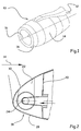
- a propulsion unit 10 of an aircraft for example connected under the wing by means of a mast 12, comprises a nacelle 14 in which is arranged in a substantially concentric engine.
- the longitudinal axis of the nacelle is referenced 16.
- the nacelle 14 comprises an inner wall delimiting a duct with an air inlet 18 at the front for channeling the air towards the engine.
- the present invention relates more particularly to a nacelle integrating a frost treatment process using hot air in contact with the inner wall of the air inlet 18, in particular hot air taken from the engine.
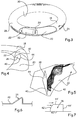
- a nacelle 14 comprises inside a partition called front frame 20 which delimits with the air inlet 18 a duct 22 which extends over the entire circumference of the nacelle and which has a substantially D-shaped section.
- This duct 22 is supplied with hot air by a system of nozzles or a supply duct 24 located, the air circulating in this duct being evacuated via an exhaust 26 visible on the figure 3 .
- the injected hot air travels through the duct 22 over 360 °. Due to a centrifugal effect, the hot air circulates further on the outside of the air inlet referenced 28 on the figure 2 .
- the defrosting capacity is not homogeneous on the circumference. It increases rapidly to obtain a maximum value and then gradually decreases over the rest of the circumference with a discontinuity of the frost treatment at the lowest level.
- the temperature at the inner side of the air inlet may not be sufficient.
- this mixer 32 does not make it possible to homogenize the temperature of the hot air over the entire circumference.
- the hot air still tends to press against the outer side 28 of the air inlet due to the centrifugal force.
- the present invention aims to overcome the drawbacks of the prior art by providing an air inlet of an aircraft nacelle comprising means for optimizing the treatment of frost.
- the subject of the invention is an air intake of an aircraft nacelle comprising a duct extending on the circumference of said air intake and delimited at the rear by a front frame, means injection device hot air localized in said conduit ensuring the circulation of hot air in the conduit along the circumference of the nacelle in one direction, characterized in that it comprises in the conduit at least one generator of vortex in the form of a plate or shape protruding from the duct wall to disturb the flow of hot air to compensate for the effect of centrifugal force and reduce the temperature gradient between the inner side and the side outside said conduit.
- FIG. 2 there is shown an air inlet 18 of an aircraft nacelle.
- the air inlet makes it possible to channel towards the engine a flow of air referenced by the arrow 34.
- the front portion of the air inlet 22 describes a substantially circular shape that extends in a plane that may be substantially perpendicular to the longitudinal axis, or not perpendicular, with the front portion located at 12 o'clock slightly advanced.
- other forms of air intake can be envisaged.
- the invention relates more particularly to a frost treatment consisting in using hot air taken from the engine.
- a nacelle comprises a partition called front frame 20 which delimits with the air inlet 18 a duct 22 called duct D which extends over the entire circumference of the nacelle and which has a shaped section of D.
- this D-shaped duct 22 comprises hot air injection means 24 in a localized manner.
- conduit D 22 comprises an exhaust 26, visible on the figure 3 .
- the injection means 24 make it possible to generate a flow in the duct 22 in the clockwise direction (as illustrated in the figures) or counterclockwise.
- a mixer 32 may be disposed inside the duct 22 just after the hot air injection means 24 in the direction of flow of the hot air flow. This mixer makes it possible to mix the hot air injected with the less hot air already present and circulating in the duct 22.
- the mixer and the injection means are not further described because they are known to those skilled in the art, in particular from the documents FR-2813581 and US 6443395 .
- the invention is not limited to this type of conduit, nor to this type of hot air supply.
- the temperature at the inner side is of the order of 520 ° K and at the outer side of the order 570 ° K while the need for frost treatment is greater on the inside than on the outside.
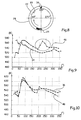
- the air inlet comprises at least one vortex generator 38 inside the duct 22 to disturb the flow of hot air which tends, without a vortex generator, to present temperature gradients between the inner side and the outer side.
- a vortex generator is a mechanical type element and is in the form of a plate or a shape projecting from the wall of the conduit (22) for disrupting the flow of hot air.
- the vortex generator 38 tends to compensate for the effect of the centrifugal force and to reduce the temperature gradient between the inner side and the outer side.
- the vortex generator 38 is fixed by suitable fixing means to the front frame 20 or to a sheet forming the air inlet 18.
- the vortex generator 38 may not be brought back but included in the frame before 20 so as not to vibrate.
- the front frame 20 is deformed so as to create a protruding shape in the duct whose profile is adapted to generate a vortex generator.
- the vortex generator 38 comprises a substantially flat plate protruding from the front frame 20, preferably perpendicular to said front frame 20.
- This plate comprises a first side 40 facing the front frame 20 and a second side 42 which the distance separating it with the first side 40 increases in the direction of flow of the hot air flow in the duct 22.
- the plate is disposed in a plane which is neither parallel nor perpendicular to the direction of flow of the air flow. hot air flowing in the duct 22.
- the plate forming the vortex generator makes an angle of the order of 20 ° to 60 ° with respect to the direction of the flow of air flowing in the duct 22.
- the plate is delimited by three sides, a first straight side 40 flattened against the front frame, a second side 42 in an arc whose first end upstream in the direction of flow is connected to the first side. and whose second downstream end is connected to a third side 44 connected to the first side 40.
- the vortex generator 38 creates at the rear of the plate a depression which tends to take off the very hot air pressed against the side outside 28 towards the middle of the duct 22 and to take off the less hot air pressed against the inner side 30 towards the middle of the duct 22.
- the plate forming the vortex generator is delimited by four sides, a first straight side 40 'plated against the front frame, a second side 42' in a circular arc having a first end upstream in the direction of flow is connected to the first side 40 'and whose second downstream end is connected to a third side 43' substantially parallel to the first side 40 'and a fourth side 44' connecting the first side 40 'to the third side 43' substantially perpendicular to the first side 40 ' .
- the plate constituting the vortex generator forms an angle with the direction of the flow of hot air flowing inside the conduit such that the upstream end of the first side 40 is closer to the axis of the nacelle as the downstream end of said first side.
- the projecting shape comprises a face which may have geometric shapes substantially identical to those of the plate.
- a temperature curve 46 is shown at the inner side 30 of the air inlet in the presence of a vortex generator 38 disposed at approximately 180 ° of the injection means 24.
- a vortex generator 38 disposed at approximately 180 ° of the injection means 24.
- a temperature curve 48 is shown at the outer side 28 of the air inlet in the presence of a vortex generator. It is noted that the temperature difference between the outer side and the inner side is greatly reduced after the vortex generator. Thus, at the position corresponding to 220 °, the temperature at the inner side is of the order of 570 ° K and at the outer side of the order of 570 ° K.
- the vortex generator 38 makes it possible to compensate the effect of the centrifugal force and to substantially increase the frost treatment capacity at the interior side after it.
- the vortex generator tends to optimize the frost treatment, the frost treatment capacity being increased without an increase in the temperature of the injected hot air and / or its flow.
- Several vortex generators 38 may be arranged along the circumference of the duct 22.
- the plate forming the vortex generator is disposed substantially in the middle of the duct 22.
- the vortex generator 38 can be connected in at least one point to the front frame or to another part of the air inlet so that a flow of air can flow between said Vortex generator and the surface of the air inlet or the front frame to which it is connected.
- the vortex generator is of simple design and inexpensive, does not require maintenance and has a significantly lower mass compared to the mixer proposed by the documents. FR-2813581 and US 6443395 .
Landscapes
- Engineering & Computer Science (AREA)
- Aviation & Aerospace Engineering (AREA)
- Structures Of Non-Positive Displacement Pumps (AREA)
Claims (9)
- Lufteinlass einer Gondel eines Luftfahrzeugs mit einem Kanal, der sich über den Umfang des Lufteinlasses erstreckt und nach hinten von einem vorderen Rahmen (20) begrenzt ist, mit Injektionsmitteln (24) für Warmluft, die derart in dem Kanal (22) angeordnet sind, dass die Zirkulation von Warmluft im Kanal entlang des Umfangs der Gondel in eine Richtung gewährleistet ist, dadurch gekennzeichnet, dass dieser im Kanal (22) wenigstens einen Verwirbler (38) aufweist, der sich von den Injektionsmitteln (24) unterscheidet und als Platte oder Vorsprung der Kanalwand ausgebildet ist, um den Fluss der Warmluft zu stören, um die Wirkung der Zentrifugalkraft zu kompensieren und den Temperaturgradienten zwischen der Innenseite und der Außenseite des Kanals (22) zu verringern.
- Lufteinlass einer Gondel eines Luftfahrzeugs nach Anspruch 1, dadurch gekennzeichnet, dass der vordere Rahmen (20) eine in den Kanal (22) vorspringende Verformung aufweist, deren Profil dazu eingerichtet ist, einen Verwirbler (38) bereitzustellen.
- Lufteinlass einer Gondel eines Luftfahrzeugs nach Anspruch 1, dadurch gekennzeichnet, dass ein Verwirbler (38) eine im Wesentlichen flache Platte aufweist, die bezüglich des vorderen Rahmens (20) vorspringt und an dem vorderen Rahmen (20) befestigt ist.
- Lufteinlass einer Gondel eines Luftfahrzeugs nach Anspruch 2 oder 3, dadurch gekennzeichnet, dass der Verwirbler eine erste Seite (40) aufweist, die zum vorderen Rahmen (20) ausgerichtet ist, und eine zweite Seite (42), deren Entfernung, die diese von der ersten Seite (40) trennt, in Flussrichtung der Warmluft in dem Kanal (22) zunimmt.
- Lufteinlass einer Gondel eines Luftfahrzeugs nach Anspruch 4, dadurch gekennzeichnet, dass der Verwirbler von drei Seiten begrenzt ist, einer ersten geradlinigen Seite (40), einer zweiten kreisbogenförmigen Seite (42), deren in Flussrichtung stromaufwärts gelegenes Ende mit der ersten Seite verbunden ist und deren stromabwärts gelegenes Ende mit einer dritten Seite (44) verbunden ist, die mit der ersten Seite (40) verbunden ist.
- Lufteinlass einer Gondel eines Luftfahrzeugs nach Anspruch 4, dadurch gekennzeichnet, dass der Verwirbler von vier Seiten begrenzt ist, einer ersten geradlinigen Seite (40'), einer zweiten kreisbogenförmigen Seite (42'), deren in Strömungsrichtung stromaufwärts gelegenes erstes Ende mit der ersten Seite (40') verbunden ist und deren zweites stromabwärts gelegenes Ende mit einer dritten Seite (43') verbunden ist, die im Wesentlichen zur ersten Seite (40') parallel ist, und einer vierten Seite (44'), die die erste Seite (40') mit der dritten Seite (43') im Wesentlichen im rechten Winkel zur ersten Seite (40') verbindet.
- Lufteinlass einer Gondel eines Luftfahrzeugs nach einem der Ansprüche 3 bis 6, dadurch gekennzeichnet, dass der Verwirbler einen Winkel in der Größenordnung von 20° bis 60° bezüglich der Flussrichtung der im Kanal (22) strömenden Luft einnimmt.
- Lufteinlass einer Gondel eines Luftfahrzeugs nach einem der Ansprüche 4 bis 7, dadurch gekennzeichnet, dass der Verwirbler (38) einen Winkel mit der im Inneren des Kanals zirkulierenden Warmluft derart bildet, dass das in Strömungsrichtung des Warmluftstroms stromaufwärts gelegene Ende der ersten Seite (40) der Achse der Gondel näher liegt als das stromabwärts gelegene Ende der ersten Seite (40).
- Gondel eines Luftfahrzeugs, die einen Lufteinlass nach einem der vorhergehenden Ansprüche umfasst.
Applications Claiming Priority (2)
| Application Number | Priority Date | Filing Date | Title |
|---|---|---|---|
| FR0959183A FR2954280B1 (fr) | 2009-12-18 | 2009-12-18 | Entree d'air d'une nacelle d'aeronef comprenant un traitement du givre optimise |
| PCT/FR2010/052702 WO2011073561A1 (fr) | 2009-12-18 | 2010-12-14 | Entree d'air d'une nacelle d'aeronef comprenant un traitement du givre optimise |
Publications (2)
| Publication Number | Publication Date |
|---|---|
| EP2512926A1 EP2512926A1 (de) | 2012-10-24 |
| EP2512926B1 true EP2512926B1 (de) | 2016-04-06 |
Family
ID=42489427
Family Applications (1)
| Application Number | Title | Priority Date | Filing Date |
|---|---|---|---|
| EP10809003.6A Not-in-force EP2512926B1 (de) | 2009-12-18 | 2010-12-14 | Lufteinlass einer flugzeuggondel mit optimiierter enteisung |
Country Status (5)
| Country | Link |
|---|---|
| US (1) | US8783619B2 (de) |
| EP (1) | EP2512926B1 (de) |
| CN (1) | CN102753438B (de) |
| FR (1) | FR2954280B1 (de) |
| WO (1) | WO2011073561A1 (de) |
Cited By (1)
| Publication number | Priority date | Publication date | Assignee | Title |
|---|---|---|---|---|
| EP4749104A1 (de) * | 2024-11-25 | 2026-05-27 | Honeywell International Inc. | Antivereisungssystem für einen abgeschirmten drallgasturbinenmotoreinlass |
Families Citing this family (16)
| Publication number | Priority date | Publication date | Assignee | Title |
|---|---|---|---|---|
| FR2954279B1 (fr) * | 2009-12-18 | 2014-08-22 | Airbus Operations Sas | Entree d'air d'une nacelle d'aeronef integrant des moyens d'injection en air chaud pour le traitement du givre optimises |
| JP5582927B2 (ja) * | 2010-08-30 | 2014-09-03 | 三菱重工業株式会社 | 航空機の防除氷システム及びこれを備える航空機 |
| US20140263837A1 (en) * | 2013-03-12 | 2014-09-18 | Spirit Aerosystems, Inc. | Nacelle inlet thermal anti-ice spray duct |
| US10167086B2 (en) | 2013-10-25 | 2019-01-01 | Short Brothers Plc | Anti-icing system for an aircraft |
| WO2015059489A1 (en) * | 2013-10-25 | 2015-04-30 | Short Brothers Plc | Anti-icing system for an aircraft |
| US9488067B2 (en) | 2014-01-14 | 2016-11-08 | The Boeing Company | Aircraft anti-icing systems having deflector vanes |
| US10138811B2 (en) | 2014-03-13 | 2018-11-27 | The Boeing Company | Enhanced temperature control anti-ice nozzle |
| US10393020B2 (en) * | 2015-08-26 | 2019-08-27 | Rohr, Inc. | Injector nozzle configuration for swirl anti-icing system |
| US10167085B2 (en) * | 2016-01-27 | 2019-01-01 | General Electric Company | Nozzle and vane system for nacelle anti-icing |
| US10189572B2 (en) * | 2016-05-02 | 2019-01-29 | The Boeing Company | Systems and methods for preventing ice formation on portions of an aircraft |
| US10513978B2 (en) | 2016-05-02 | 2019-12-24 | General Electric Company | Directed flow nozzle swirl enhancer |
| FR3060651B1 (fr) * | 2016-12-20 | 2020-11-06 | Airbus Operations Sas | Structure d'entree d'air pour une nacelle d'aeronef |
| FR3072421B1 (fr) * | 2017-10-18 | 2019-09-27 | Airbus Operations | Levre d'entree d'air d'un moteur d'aeronef comportant un systeme de degivrage |
| FR3077268A1 (fr) | 2018-01-26 | 2019-08-02 | Airbus Operations | Dispositif de degivrage d'une surface configure pour ne pas generer d'interference electromagnetique |
| FR3079631B1 (fr) * | 2018-03-27 | 2020-03-20 | Airbus Operations | Systeme et procede de controle de la trajectoire d'un aeronef. |
| FR3145926A1 (fr) * | 2023-02-20 | 2024-08-23 | Safran Nacelles | Entrée d’air pour une nacelle d’aéronef et procédé de dégivrage associé |
Family Cites Families (15)
| Publication number | Priority date | Publication date | Assignee | Title |
|---|---|---|---|---|
| US4688745A (en) * | 1986-01-24 | 1987-08-25 | Rohr Industries, Inc. | Swirl anti-ice system |
| US5088277A (en) * | 1988-10-03 | 1992-02-18 | General Electric Company | Aircraft engine inlet cowl anti-icing system |
| US5058837A (en) * | 1989-04-07 | 1991-10-22 | Wheeler Gary O | Low drag vortex generators |
| US6227800B1 (en) * | 1998-11-24 | 2001-05-08 | General Electric Company | Bay cooled turbine casing |
| US6267328B1 (en) * | 1999-10-21 | 2001-07-31 | Rohr, Inc. | Hot air injection for swirling rotational anti-icing system |
| US6354538B1 (en) * | 1999-10-25 | 2002-03-12 | Rohr, Inc. | Passive control of hot air injection for swirling rotational type anti-icing system |
| US6371411B1 (en) * | 1999-11-23 | 2002-04-16 | The Boeing Company | Method and apparatus for aircraft inlet ice protection |
| US6688558B2 (en) * | 1999-11-23 | 2004-02-10 | The Boeing Company | Method and apparatus for aircraft inlet ice protection |
| FR2813581B1 (fr) * | 2000-09-06 | 2002-11-29 | Aerospatiale Matra Airbus | Capot d'entree d'air de moteur a reaction pourvu de moyens de degivrage |
| GB0211800D0 (en) * | 2002-05-22 | 2002-07-03 | Short Brothers Plc | An ice protection system for aircraft structures |
| IL165233A (en) * | 2004-11-16 | 2013-06-27 | Israel Hirshberg | Energy conversion facility |
| FR2921901B1 (fr) * | 2007-10-08 | 2011-03-18 | Aircelle Sa | Structure d'entree d'air apte a etre montee en amont d'une structure mediane de nacelle pour moteur d'aeronef, et nacelle equipee d'une telle structure d'entree d'air |
| US20090108134A1 (en) * | 2007-10-25 | 2009-04-30 | General Electric Company | Icing protection system and method for enhancing heat transfer |
| FR2924407B1 (fr) * | 2007-12-03 | 2010-05-14 | Airbus France | Systeme de sortie d'air pour un bord d'attaque d'aeronef |
| US8061657B2 (en) * | 2008-12-31 | 2011-11-22 | General Electric Company | Method and apparatus for aircraft anti-icing |
-
2009
- 2009-12-18 FR FR0959183A patent/FR2954280B1/fr not_active Expired - Fee Related
-
2010
- 2010-12-14 CN CN201080059358.1A patent/CN102753438B/zh not_active Expired - Fee Related
- 2010-12-14 EP EP10809003.6A patent/EP2512926B1/de not_active Not-in-force
- 2010-12-14 WO PCT/FR2010/052702 patent/WO2011073561A1/fr not_active Ceased
- 2010-12-14 US US13/515,880 patent/US8783619B2/en active Active
Cited By (1)
| Publication number | Priority date | Publication date | Assignee | Title |
|---|---|---|---|---|
| EP4749104A1 (de) * | 2024-11-25 | 2026-05-27 | Honeywell International Inc. | Antivereisungssystem für einen abgeschirmten drallgasturbinenmotoreinlass |
Also Published As
| Publication number | Publication date |
|---|---|
| US20120248249A1 (en) | 2012-10-04 |
| FR2954280A1 (fr) | 2011-06-24 |
| WO2011073561A1 (fr) | 2011-06-23 |
| CN102753438B (zh) | 2015-11-25 |
| US8783619B2 (en) | 2014-07-22 |
| CN102753438A (zh) | 2012-10-24 |
| FR2954280B1 (fr) | 2012-03-23 |
| EP2512926A1 (de) | 2012-10-24 |
Similar Documents
| Publication | Publication Date | Title |
|---|---|---|
| WO2011073561A1 (fr) | Entree d'air d'une nacelle d'aeronef comprenant un traitement du givre optimise | |
| EP2231474B1 (de) | Triebwerksgondel mit einem optimierten EisbehandlungsSYSTEM | |
| EP2391542B1 (de) | Triebwerksverkleidung mit lärmschutzvorrichtung | |
| EP2512927B1 (de) | Triebwerksgondellufteinlass eines flugzeugs mit einer vorrichtung zur heisslufteinspritzung zur optimierten enteisungsbehandlung | |
| EP2274205B1 (de) | Zwischen dem motor und dem lufteinlass einer flugzeuggondel befindliche wellenabschwächungsarmatur | |
| EP2222560B1 (de) | Anlage für eine flugzeuggondelführungssystem | |
| EP2179163B1 (de) | Zacke für eine Düse, zugehörige Düse und Turbotriebwerk | |
| EP2516270B1 (de) | Schallbehandlungsplatte mit skalierbarer dicke | |
| EP3839238B1 (de) | Ausgangskonus einer antriebseinheit eines luftfahrzeugs, der ein akustisches verarbeitungssystem mit mindestens zwei freiheitsgraden bildet | |
| FR2858999A1 (fr) | Turbomachine pour aeronef a emissions de bruit reduites | |
| EP2917108A1 (de) | Durch ein turbinenstrahltriebwerk mit gegendrehenden lüftern angetriebenes flugzeug | |
| FR3043984A1 (fr) | Avion propulse par une turbomachine muni d'un ecran acoustique | |
| FR2983834A1 (fr) | Pylone d'accrochage pour turbomachine | |
| EP2791006B1 (de) | Lufteinlassstruktur für eine turbostrahl-motorengondel | |
| FR2935349A1 (fr) | Turbomachine a helices non carenees | |
| EP3959135A1 (de) | Lufteinlass für eine turbojet-triebwerksgondel | |
| FR3014413A1 (fr) | Dispositif d'ejection d'air comprenant un profil aerodynamique muni d'une languette flexible d'obturation de fente | |
| FR2952032A1 (fr) | Nacelle d'aeronef comprenant un systeme de traitement acoustique optimise | |
| FR3120352A1 (fr) | Entree d’air de nacelle munie d’un système de protection contre la glace mixte | |
| FR3055922A1 (fr) | Ensemble propulsif d'aeronef comprenant une liaison entre une entree d'air et une motorisation | |
| EP1813529A1 (de) | Lufteinlass eines Zweistrom-Turbinentriebwerks | |
| FR3049571B1 (fr) | Aile d'aeronef a traitement acoustique amelioree | |
| FR2990928A1 (fr) | Nacelle de moteur a turbine a gaz | |
| FR2941675A1 (fr) | Nacelle d'aeronef comprenant un systeme de traitement acoustique optimise. | |
| CA2837605A1 (fr) | Structure d'entree d'air de nacelle de turboreacteur |
Legal Events
| Date | Code | Title | Description |
|---|---|---|---|
| PUAI | Public reference made under article 153(3) epc to a published international application that has entered the european phase |
Free format text: ORIGINAL CODE: 0009012 |
|
| 17P | Request for examination filed |
Effective date: 20120615 |
|
| AK | Designated contracting states |
Kind code of ref document: A1 Designated state(s): AL AT BE BG CH CY CZ DE DK EE ES FI FR GB GR HR HU IE IS IT LI LT LU LV MC MK MT NL NO PL PT RO RS SE SI SK SM TR |
|
| DAX | Request for extension of the european patent (deleted) | ||
| GRAP | Despatch of communication of intention to grant a patent |
Free format text: ORIGINAL CODE: EPIDOSNIGR1 |
|
| RIC1 | Information provided on ipc code assigned before grant |
Ipc: B64D 33/02 20060101ALI20150929BHEP Ipc: B64D 15/04 20060101AFI20150929BHEP |
|
| INTG | Intention to grant announced |
Effective date: 20151028 |
|
| GRAS | Grant fee paid |
Free format text: ORIGINAL CODE: EPIDOSNIGR3 |
|
| GRAA | (expected) grant |
Free format text: ORIGINAL CODE: 0009210 |
|
| AK | Designated contracting states |
Kind code of ref document: B1 Designated state(s): AL AT BE BG CH CY CZ DE DK EE ES FI FR GB GR HR HU IE IS IT LI LT LU LV MC MK MT NL NO PL PT RO RS SE SI SK SM TR |
|
| REG | Reference to a national code |
Ref country code: GB Ref legal event code: FG4D Free format text: NOT ENGLISH |
|
| REG | Reference to a national code |
Ref country code: AT Ref legal event code: REF Ref document number: 787502 Country of ref document: AT Kind code of ref document: T Effective date: 20160415 Ref country code: CH Ref legal event code: EP |
|
| REG | Reference to a national code |
Ref country code: IE Ref legal event code: FG4D Free format text: LANGUAGE OF EP DOCUMENT: FRENCH |
|
| REG | Reference to a national code |
Ref country code: DE Ref legal event code: R096 Ref document number: 602010032111 Country of ref document: DE |
|
| REG | Reference to a national code |
Ref country code: LT Ref legal event code: MG4D Ref country code: NL Ref legal event code: MP Effective date: 20160406 |
|
| REG | Reference to a national code |
Ref country code: AT Ref legal event code: MK05 Ref document number: 787502 Country of ref document: AT Kind code of ref document: T Effective date: 20160406 |
|
| PG25 | Lapsed in a contracting state [announced via postgrant information from national office to epo] |
Ref country code: NL Free format text: LAPSE BECAUSE OF FAILURE TO SUBMIT A TRANSLATION OF THE DESCRIPTION OR TO PAY THE FEE WITHIN THE PRESCRIBED TIME-LIMIT Effective date: 20160406 |
|
| PG25 | Lapsed in a contracting state [announced via postgrant information from national office to epo] |
Ref country code: LT Free format text: LAPSE BECAUSE OF FAILURE TO SUBMIT A TRANSLATION OF THE DESCRIPTION OR TO PAY THE FEE WITHIN THE PRESCRIBED TIME-LIMIT Effective date: 20160406 Ref country code: FI Free format text: LAPSE BECAUSE OF FAILURE TO SUBMIT A TRANSLATION OF THE DESCRIPTION OR TO PAY THE FEE WITHIN THE PRESCRIBED TIME-LIMIT Effective date: 20160406 Ref country code: IS Free format text: LAPSE BECAUSE OF FAILURE TO SUBMIT A TRANSLATION OF THE DESCRIPTION OR TO PAY THE FEE WITHIN THE PRESCRIBED TIME-LIMIT Effective date: 20160806 Ref country code: PL Free format text: LAPSE BECAUSE OF FAILURE TO SUBMIT A TRANSLATION OF THE DESCRIPTION OR TO PAY THE FEE WITHIN THE PRESCRIBED TIME-LIMIT Effective date: 20160406 Ref country code: NO Free format text: LAPSE BECAUSE OF FAILURE TO SUBMIT A TRANSLATION OF THE DESCRIPTION OR TO PAY THE FEE WITHIN THE PRESCRIBED TIME-LIMIT Effective date: 20160706 |
|
| PG25 | Lapsed in a contracting state [announced via postgrant information from national office to epo] |
Ref country code: SE Free format text: LAPSE BECAUSE OF FAILURE TO SUBMIT A TRANSLATION OF THE DESCRIPTION OR TO PAY THE FEE WITHIN THE PRESCRIBED TIME-LIMIT Effective date: 20160406 Ref country code: ES Free format text: LAPSE BECAUSE OF FAILURE TO SUBMIT A TRANSLATION OF THE DESCRIPTION OR TO PAY THE FEE WITHIN THE PRESCRIBED TIME-LIMIT Effective date: 20160406 Ref country code: LV Free format text: LAPSE BECAUSE OF FAILURE TO SUBMIT A TRANSLATION OF THE DESCRIPTION OR TO PAY THE FEE WITHIN THE PRESCRIBED TIME-LIMIT Effective date: 20160406 Ref country code: AT Free format text: LAPSE BECAUSE OF FAILURE TO SUBMIT A TRANSLATION OF THE DESCRIPTION OR TO PAY THE FEE WITHIN THE PRESCRIBED TIME-LIMIT Effective date: 20160406 Ref country code: PT Free format text: LAPSE BECAUSE OF FAILURE TO SUBMIT A TRANSLATION OF THE DESCRIPTION OR TO PAY THE FEE WITHIN THE PRESCRIBED TIME-LIMIT Effective date: 20160808 Ref country code: GR Free format text: LAPSE BECAUSE OF FAILURE TO SUBMIT A TRANSLATION OF THE DESCRIPTION OR TO PAY THE FEE WITHIN THE PRESCRIBED TIME-LIMIT Effective date: 20160707 Ref country code: RS Free format text: LAPSE BECAUSE OF FAILURE TO SUBMIT A TRANSLATION OF THE DESCRIPTION OR TO PAY THE FEE WITHIN THE PRESCRIBED TIME-LIMIT Effective date: 20160406 Ref country code: HR Free format text: LAPSE BECAUSE OF FAILURE TO SUBMIT A TRANSLATION OF THE DESCRIPTION OR TO PAY THE FEE WITHIN THE PRESCRIBED TIME-LIMIT Effective date: 20160406 |
|
| REG | Reference to a national code |
Ref country code: FR Ref legal event code: PLFP Year of fee payment: 7 |
|
| PG25 | Lapsed in a contracting state [announced via postgrant information from national office to epo] |
Ref country code: IT Free format text: LAPSE BECAUSE OF FAILURE TO SUBMIT A TRANSLATION OF THE DESCRIPTION OR TO PAY THE FEE WITHIN THE PRESCRIBED TIME-LIMIT Effective date: 20160406 |
|
| REG | Reference to a national code |
Ref country code: DE Ref legal event code: R097 Ref document number: 602010032111 Country of ref document: DE |
|
| PG25 | Lapsed in a contracting state [announced via postgrant information from national office to epo] |
Ref country code: SK Free format text: LAPSE BECAUSE OF FAILURE TO SUBMIT A TRANSLATION OF THE DESCRIPTION OR TO PAY THE FEE WITHIN THE PRESCRIBED TIME-LIMIT Effective date: 20160406 Ref country code: CZ Free format text: LAPSE BECAUSE OF FAILURE TO SUBMIT A TRANSLATION OF THE DESCRIPTION OR TO PAY THE FEE WITHIN THE PRESCRIBED TIME-LIMIT Effective date: 20160406 Ref country code: DK Free format text: LAPSE BECAUSE OF FAILURE TO SUBMIT A TRANSLATION OF THE DESCRIPTION OR TO PAY THE FEE WITHIN THE PRESCRIBED TIME-LIMIT Effective date: 20160406 Ref country code: RO Free format text: LAPSE BECAUSE OF FAILURE TO SUBMIT A TRANSLATION OF THE DESCRIPTION OR TO PAY THE FEE WITHIN THE PRESCRIBED TIME-LIMIT Effective date: 20160406 Ref country code: EE Free format text: LAPSE BECAUSE OF FAILURE TO SUBMIT A TRANSLATION OF THE DESCRIPTION OR TO PAY THE FEE WITHIN THE PRESCRIBED TIME-LIMIT Effective date: 20160406 |
|
| PLBE | No opposition filed within time limit |
Free format text: ORIGINAL CODE: 0009261 |
|
| STAA | Information on the status of an ep patent application or granted ep patent |
Free format text: STATUS: NO OPPOSITION FILED WITHIN TIME LIMIT |
|
| PG25 | Lapsed in a contracting state [announced via postgrant information from national office to epo] |
Ref country code: SM Free format text: LAPSE BECAUSE OF FAILURE TO SUBMIT A TRANSLATION OF THE DESCRIPTION OR TO PAY THE FEE WITHIN THE PRESCRIBED TIME-LIMIT Effective date: 20160406 |
|
| 26N | No opposition filed |
Effective date: 20170110 |
|
| PG25 | Lapsed in a contracting state [announced via postgrant information from national office to epo] |
Ref country code: SI Free format text: LAPSE BECAUSE OF FAILURE TO SUBMIT A TRANSLATION OF THE DESCRIPTION OR TO PAY THE FEE WITHIN THE PRESCRIBED TIME-LIMIT Effective date: 20160406 Ref country code: BE Free format text: LAPSE BECAUSE OF NON-PAYMENT OF DUE FEES Effective date: 20161231 |
|
| REG | Reference to a national code |
Ref country code: CH Ref legal event code: PL |
|
| PG25 | Lapsed in a contracting state [announced via postgrant information from national office to epo] |
Ref country code: MC Free format text: LAPSE BECAUSE OF FAILURE TO SUBMIT A TRANSLATION OF THE DESCRIPTION OR TO PAY THE FEE WITHIN THE PRESCRIBED TIME-LIMIT Effective date: 20160406 |
|
| REG | Reference to a national code |
Ref country code: IE Ref legal event code: MM4A |
|
| PG25 | Lapsed in a contracting state [announced via postgrant information from national office to epo] |
Ref country code: LU Free format text: LAPSE BECAUSE OF NON-PAYMENT OF DUE FEES Effective date: 20161214 Ref country code: CH Free format text: LAPSE BECAUSE OF NON-PAYMENT OF DUE FEES Effective date: 20161231 Ref country code: LI Free format text: LAPSE BECAUSE OF NON-PAYMENT OF DUE FEES Effective date: 20161231 |
|
| PG25 | Lapsed in a contracting state [announced via postgrant information from national office to epo] |
Ref country code: IE Free format text: LAPSE BECAUSE OF NON-PAYMENT OF DUE FEES Effective date: 20161214 |
|
| REG | Reference to a national code |
Ref country code: FR Ref legal event code: PLFP Year of fee payment: 8 |
|
| REG | Reference to a national code |
Ref country code: BE Ref legal event code: MM Effective date: 20161231 |
|
| PG25 | Lapsed in a contracting state [announced via postgrant information from national office to epo] |
Ref country code: HU Free format text: LAPSE BECAUSE OF FAILURE TO SUBMIT A TRANSLATION OF THE DESCRIPTION OR TO PAY THE FEE WITHIN THE PRESCRIBED TIME-LIMIT; INVALID AB INITIO Effective date: 20101214 Ref country code: CY Free format text: LAPSE BECAUSE OF FAILURE TO SUBMIT A TRANSLATION OF THE DESCRIPTION OR TO PAY THE FEE WITHIN THE PRESCRIBED TIME-LIMIT Effective date: 20160406 |
|
| PG25 | Lapsed in a contracting state [announced via postgrant information from national office to epo] |
Ref country code: TR Free format text: LAPSE BECAUSE OF FAILURE TO SUBMIT A TRANSLATION OF THE DESCRIPTION OR TO PAY THE FEE WITHIN THE PRESCRIBED TIME-LIMIT Effective date: 20160406 Ref country code: MK Free format text: LAPSE BECAUSE OF FAILURE TO SUBMIT A TRANSLATION OF THE DESCRIPTION OR TO PAY THE FEE WITHIN THE PRESCRIBED TIME-LIMIT Effective date: 20160406 |
|
| PG25 | Lapsed in a contracting state [announced via postgrant information from national office to epo] |
Ref country code: BG Free format text: LAPSE BECAUSE OF FAILURE TO SUBMIT A TRANSLATION OF THE DESCRIPTION OR TO PAY THE FEE WITHIN THE PRESCRIBED TIME-LIMIT Effective date: 20160406 |
|
| PG25 | Lapsed in a contracting state [announced via postgrant information from national office to epo] |
Ref country code: MT Free format text: LAPSE BECAUSE OF FAILURE TO SUBMIT A TRANSLATION OF THE DESCRIPTION OR TO PAY THE FEE WITHIN THE PRESCRIBED TIME-LIMIT Effective date: 20160406 |
|
| PG25 | Lapsed in a contracting state [announced via postgrant information from national office to epo] |
Ref country code: AL Free format text: LAPSE BECAUSE OF FAILURE TO SUBMIT A TRANSLATION OF THE DESCRIPTION OR TO PAY THE FEE WITHIN THE PRESCRIBED TIME-LIMIT Effective date: 20160406 |
|
| PGFP | Annual fee paid to national office [announced via postgrant information from national office to epo] |
Ref country code: DE Payment date: 20211210 Year of fee payment: 12 |
|
| REG | Reference to a national code |
Ref country code: DE Ref legal event code: R119 Ref document number: 602010032111 Country of ref document: DE |
|
| PG25 | Lapsed in a contracting state [announced via postgrant information from national office to epo] |
Ref country code: DE Free format text: LAPSE BECAUSE OF NON-PAYMENT OF DUE FEES Effective date: 20230701 |
|
| PGFP | Annual fee paid to national office [announced via postgrant information from national office to epo] |
Ref country code: GB Payment date: 20231220 Year of fee payment: 14 |
|
| PGFP | Annual fee paid to national office [announced via postgrant information from national office to epo] |
Ref country code: FR Payment date: 20231221 Year of fee payment: 14 |
|
| GBPC | Gb: european patent ceased through non-payment of renewal fee |
Effective date: 20241214 |
|
| PG25 | Lapsed in a contracting state [announced via postgrant information from national office to epo] |
Ref country code: GB Free format text: LAPSE BECAUSE OF NON-PAYMENT OF DUE FEES Effective date: 20241214 |
|
| PG25 | Lapsed in a contracting state [announced via postgrant information from national office to epo] |
Ref country code: FR Free format text: LAPSE BECAUSE OF NON-PAYMENT OF DUE FEES Effective date: 20241231 |