EP2512142A2 - Procédé et appareil d'extraction d'une image de texture et d'une image de profondeur - Google Patents
Procédé et appareil d'extraction d'une image de texture et d'une image de profondeur Download PDFInfo
- Publication number
- EP2512142A2 EP2512142A2 EP10836208A EP10836208A EP2512142A2 EP 2512142 A2 EP2512142 A2 EP 2512142A2 EP 10836208 A EP10836208 A EP 10836208A EP 10836208 A EP10836208 A EP 10836208A EP 2512142 A2 EP2512142 A2 EP 2512142A2
- Authority
- EP
- European Patent Office
- Prior art keywords
- image
- pattern
- target object
- scene
- texture
- Prior art date
- Legal status (The legal status is an assumption and is not a legal conclusion. Google has not performed a legal analysis and makes no representation as to the accuracy of the status listed.)
- Withdrawn
Links
Images


Classifications
-
- H—ELECTRICITY
- H04—ELECTRIC COMMUNICATION TECHNIQUE
- H04N—PICTORIAL COMMUNICATION, e.g. TELEVISION
- H04N13/00—Stereoscopic video systems; Multi-view video systems; Details thereof
- H04N13/20—Image signal generators
- H04N13/204—Image signal generators using stereoscopic image cameras
- H04N13/207—Image signal generators using stereoscopic image cameras using a single 2D image sensor
-
- H—ELECTRICITY
- H04—ELECTRIC COMMUNICATION TECHNIQUE
- H04N—PICTORIAL COMMUNICATION, e.g. TELEVISION
- H04N13/00—Stereoscopic video systems; Multi-view video systems; Details thereof
- H04N13/20—Image signal generators
- H04N13/204—Image signal generators using stereoscopic image cameras
- H04N13/254—Image signal generators using stereoscopic image cameras in combination with electromagnetic radiation sources for illuminating objects
-
- H—ELECTRICITY
- H04—ELECTRIC COMMUNICATION TECHNIQUE
- H04N—PICTORIAL COMMUNICATION, e.g. TELEVISION
- H04N13/00—Stereoscopic video systems; Multi-view video systems; Details thereof
- H04N13/20—Image signal generators
- H04N13/257—Colour aspects
-
- H—ELECTRICITY
- H04—ELECTRIC COMMUNICATION TECHNIQUE
- H04N—PICTORIAL COMMUNICATION, e.g. TELEVISION
- H04N13/00—Stereoscopic video systems; Multi-view video systems; Details thereof
- H04N2013/0074—Stereoscopic image analysis
- H04N2013/0081—Depth or disparity estimation from stereoscopic image signals
Definitions
- the present invention relates to an apparatus and a method for extracting a texture image and a depth image, and more particularly, to an apparatus and a method that may simultaneously extract the texture image and the depth image by projecting a pattern image that may be temporally integrated to be a white image.
- a method of extracting the depth information in a 3D technology uses a stereo scheme.
- the stereo scheme indicates usage of a left image and a right image for a 3D display.
- both the left image and the right image are transmitted in order to provide a 3DTV service, a problem with a bandwidth of a transmission channel may arise.
- a method using the depth information is provided to resolve the problem with the bandwidth.
- a suggested new method may transmit a texture image corresponding to a color image, and a depth image corresponding to the texture image, and may compose a stereo image using scene composition, thereby resolving the bandwidth problem.
- a texture image and a depth image are difficult to obtain using a conventional method when a target object is dynamic. Also, when the target object corresponds to a human, a white light that may be projected to the human in order to obtain the texture image and the depth image caused inconvenience to a vision of the human. In addition, when a color exists on a surface of the target object included in a 3D image, or an ambience illumination exists in the target object, accuracy of the texture image is reduced.
- An aspect of the present invention provides an apparatus and a method that may capture a scene image by consecutively projecting, on a target object, a pattern image that may be temporally integrated to be a white light, thereby simultaneously obtaining a texture image and a depth image of the target object.
- An aspect of the present invention provides an apparatus and a method that may project, on a target object, a pattern image that may be temporally integrated to be a white light, thereby preventing inconvenience caused to a vision of a human due to projection of the white light.
- An aspect of the present invention provides an apparatus and a method that may obtain correspondence points robust against a color on a surface of a target object, and an ambience illumination by decoding a pattern image encoded by verifying a color of a scene image using a texture image of the target object.
- an apparatus including a pattern image projecting unit to project a pattern image on a target object, an image capturing unit to capture a scene image on which the pattern image is reflected from the target object, and an image processing unit to extract a texture image and a depth image using the captured scene image.
- a method including projecting, by a pattern image projecting unit, a pattern image on a target object, capturing, by an image capturing unit, a scene image on which the pattern image is reflected from the target object, and extracting, by an image processing unit, a texture image and a depth image using the captured scene image.
- a texture image and a depth image of a target object by consecutively projecting, on a target object, a pattern image that may be temporally integrated to be a white light, and capturing a scene image.
- the present invention it is possible to prevent inconvenience caused to a vision of a human due to projection of a white light, by projecting, on a target object, a pattern image that may be temporally integrated to be the white light.
- correspondence points that may be robust against a color on a surface of a target object, and against an ambience illumination, by decoding a pattern image encoded by verifying a color of a scene image using a texture image of the target object.
- FIG. 1 is a diagram illustrating an apparatus for simultaneously extracting a texture image and a depth image according to an embodiment of the present invention.
- an apparatus 101 may include a pattern image projecting unit 102, an image capturing unit 103, and an image processing unit 104.
- the pattern image projecting unit 102 may project a pattern image on a target object 105.
- the pattern image projecting unit 102 may store the pattern image in a buffer, and may sequentially and repeatedly project the pattern image stored in the buffer based on a synchronizing signal of the image processing unit 104. That is, the pattern image projecting unit 102 may project, on the target object 105, a pattern image where predetermined information is encoded, based on a structured light technique.
- the pattern image projecting unit 102 may project the pattern image based on a temporal pattern arrangement, or a spatial pattern arrangement.
- the pattern image projecting unit 102 may project a pattern image based on a De Bruijin pattern arrangement among spatial pattern arrangements.
- the pattern image according to an embodiment of the present invention may be projected on the target object 105 at a high speed based on the pattern arrangement.
- the pattern image when the pattern image is integrated for a predetermined period of time, the pattern image may produce an effect analogous to projecting a white light. That is, the pattern image may be classified as red (R), green (G), and blue (B) in a high speed camera, whereas the pattern may be classified based on a white light combined with R, G, and B in a general camera.
- the effect analogous to projecting a single white light may be produced by consecutively projecting the pattern image including R, G, and B for each pixel of the target object 105. Then, a single texture image 106 and a depth image 107 may be obtained from a scene image on which three pattern images are reflected from the target object 105.
- the image capturing unit 103 may capture the scene image on which the pattern image is reflected from the target object 105.
- the image capturing unit 103 may capture the scene image on which the pattern image is projected on the target object 105 and reflected from the target object 105.
- the image capturing unit 103 may include at least one camera, and a type of the camera may correspond to a general camera or a high speed camera.
- the general camera may recognize the pattern image as a white light, as opposed to classifying the pattern image as R, G, and B.
- the high speed camera may refer to a camera that may classify the pattern image as R, G, and B.
- the image processing unit 104 may extract the texture image 106 and the depth image 107 with respect to the target object 105 using the captured scene image.
- the image processing unit 104 may extract the depth image 107 by applying a structured light technique and a stereo matching technique.
- a structured light technique may be used.
- the stereo matching technique may be used.
- the structured light technique may be used.
- the stereo matching technique may basically refer to a technique to obtain correspondence points between captured images after at least two images, each having a different viewpoint, are captured.
- three-dimensional (3D) depth information may be obtained by applying trigonometry to the correspondence points.
- 3D three-dimensional
- the structured light technique may project a predetermined pattern light and remove the ambiguity, thereby calculating the correspondence points, even when the surface of the target object 105 is homogenous.
- the structured light technique may obtain the correspondence points by projecting, on the target object 105, a pattern image where predetermined information is encoded, then by capturing a scene image reflected from the target object 105, and by decoding the captured scene image.
- the scene image is decoded, verification of a color of the scene image may be important.
- the color of the scene image may be verified based on the texture image of the target object 105.
- an effect by a color on the surface of the target object 105 or an ambience illumination may be removable, and thus the scene image may be decoded to be more robust.
- the image processing unit 104 may extract the texture image 106 of the target object 105 using various schemes.
- a different scheme of extracting the texture image 106 of the target object 105 may be used when the image capturing unit 103 corresponds to a high speed camera or a general camera.
- the image processing unit 104 may average scene images captured by the image capturing unit 103, and may extract the texture image 106 of the target object 105.
- the image capturing unit 103 corresponds to the general camera, the image capturing unit 103 may capture a scene image that may be temporally integrated by maintaining a shutter speed to be relatively long. Then, the image processing unit 104 may extract the texture image 106 of the target object 105 using the temporally integrated scene image.
- each of the general camera and the high speed camera may capture the scene image on which the pattern image is reflected from the target object 105, using a beam splitter.
- a process of extracting the texture image 106 and the depth image 107 of the target object 105 will be further described.
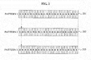
- FIG. 2 illustrates a pattern arrangement of a pattern image according to an embodiment of the present invention.
- the pattern image projecting unit 102 may project a pattern image based on a De Bruijin pattern arrangement as illustrated in FIG. 2 .
- the pattern image may be projected on a target object in a spatial order of a pattern 1, 201, a pattern 2, 202, and a pattern 3, 203. That is, a single stripe color may be temporally changed in an order of R, G, and B based on the order of the pattern 1, 201, the pattern 2, 202, and the pattern 3, 203.
- a vision of a human may integrate the pattern image for a predetermined period of time, and finally sense the pattern image as a white light.
- an analogous effect may be produced even when the stripe color is arranged in an order of R, B, and G as well as the order of R, G, and B. Accordingly, a number of information included in the encoded pattern image may be doubled based on a temporal pattern arrangement, as well as, a spatial pattern arrangement.
- an analogous effect may be produced by projecting a pattern image where predetermined information is encoded, instead of projecting a white light that may cause inconvenience to a vision of the human, in order to extract a texture image of a target object.
- FIG. 3 is a diagram illustrating a process of extracting a texture image from a scene image according to an embodiment of the present invention.
- FIG. 3 a process of extracting a texture image from a scene image on which a target image is reflected from the target object.
- FIG. 3 illustrates a process of extracting a texture image 304 when the image capturing unit 103 captures a scene image 1, 301, a scene image 2, 302, and a scene image 3, 303.
- the image capturing unit 103 may capture the scene image 1, 301, the scene image 2, 302, and the scene image 3, 303 based on a pattern image projected by the pattern image projecting unit 102. Then, the image processing unit 104 may extract the texture image 304 with respect to the target object by calculating an average of the scene image 1, 301, the scene image 2, 302, and the scene image 3, 303.
- the texture image 304 may be extracted when a white light is projected, however, according to an embodiment of the present invention; the texture image 304 may be extracted using a characteristic of the white light, the characteristic that the white light is extracted when pattern images are temporally integrated.
- the target object corresponds to a human
- direct projection of the white light may cause inconvenience to a vision of the human, and thus an effect analogous to projecting the white light may be produced by consecutively projecting the pattern image.
- FIG. 4 is a diagram illustrating a process of capturing a scene image into which a pattern image is temporally integrated according to an embodiment of the present invention.
- FIG. 4 illustrates a case that the image capturing unit 103 corresponding to a general camera captures a scene image.
- the image capturing unit 103 may capture the scene image into which three successive pattern images are temporally integrated by maintaining a shutter speed to be relatively long, that is, to have a relatively long exposure time.
- the scene image into which the pattern image is temporally integrated may have an effect analogous to the scene image on which a white light is projected on a target object and reflected from the target object.
- the image processing unit 104 may extract a texture image of the target object from the captured scene image.
- FIG. 5 is a diagram illustrating a process of capturing a scene image using a beam splitter according to an embodiment of the present invention.
- FIG. 5 illustrates that an image capturing unit 501 corresponding to a general camera, and an image capturing unit 502 corresponding to a high speed camera may simultaneously capture a scene image on which a pattern image is projected on a target object 504, and reflected from the target object 504, using a beam splitter 502.
- the general camera image capturing unit 501 may be used to obtain a texture image similar to an image obtained by projecting a white light by an effect that a pattern image is temporally integrated, and the high speed camera image capturing unit 502 may be used to extract depth information by obtaining the pattern image.
- FIG. 6 illustrates a relation between a surface of a target object and a reflected light according to an embodiment of the present invention.
- a color of a scene image captured by the image capturing unit 103 may be needed to be verified.
- the scene image may indicate an image on which the pattern image is projected on a target object and reflected from the target object.
- the image processing unit 104 may verify the color of the scene image using a texture image of the target object.
- a texture image of the target object When the texture image of the target object is used, an effect by a color of a surface of the target object or by an ambience illumination may be removable, and thus a more robust decoding may be performed.
- the color of the scene. image that may be reflected based on the color of the surface of the target object or the ambiance illumination may be different.
- R in a white light projected on the target object may become a reflected light, and all of the other colors may become absorbed lights.
- the white light may have an effect analogous to sequentially projecting the pattern image.
- the scene image reflected from the target object may include R.
- the scene image reflected from the target object may include G.
- FIG. 7 illustrates a CIE Lab chart according to an embodiment of the present invention.
- FIG. 7 illustrates a CIE Lab model showing how a color of a scene image captured by the image capturing unit 103 may be changed when a color of a surface of a target object corresponds to a reddish color, a greenish color, and a bluish color, and a color of a light projected on the target object corresponds to R, G, B, and white.
- the color of the light projected on the target object may correspond to the color of a pattern image projected on the target object.
- coordinates of four lights projected on the target object may be biased towards the color of the surface of the target object.
- the image capturing unit 103 captures a scene image on which R, G, and B are projected on the target object and reflected from the target object, and the image processing unit 104 calculates an average of captured scene images
- the color of the surface of the target object may be obtained.
- the color of the scene image may be obtained. A process of verifying the color of the scene image will be further described in FIG. 8 .
- FIG. 8 parts (a), (b), and (c), illustrates an example of verifying a color of a scene image according to an embodiment of the present invention.
- the part (a) 801 illustrates an average color of a scene image. Then, in the part (b) 802, a shifted color having a less difference from a color of the scene image among three shifted colors generated by adding R, G, and B to the average color may be verified as colors c1, c2, and c3 of the scene image.
- FIG. 9 illustrates a synchronizing signal between a pattern projecting unit and an image capturing unit according to an embodiment of the present invention.
- a synchronizing signal between the pattern image projecting unit 102 and the image capturing unit 103 may be needed.
- FIG. 9 a time diagram with respect to a shutter signal of the image capturing unit 103 based on a trigger signal of the pattern image projecting unit 102 to project a pattern image is illustrated.
- the image capturing unit 103 corresponds to a high speed camera or a general camera, different time diagrams may be shown.
- the shutter signal of the image capturing unit 103 may be maintained during a period when the trigger signal of the pattern image projecting unit 102 occurs.
- a cycle of a signal may be relatively short, whereas when the image capturing unit 103 corresponds to the general camera, the cycle of the signal may be relatively long.
- the image capturing unit 103 corresponding to the high speed camera may capture each of three scene images on which R, G, and B of the pattern image are reflected, whereas the image capturing unit 103 corresponding to the general camera may capture a single scene image into which R, G, and B of the pattern image is reflected and temporally integrated.
- FIG. 10 illustrates a synchronizing signal between a pattern projecting unit and an image capturing unit according to another embodiment of the present invention.
- FIG. 10 when compared with FIG. 9 , a cycle of a trigger signal of the pattern image capturing unit 102 may be relatively shorter. That is, FIG. 10 may indicate a case of a high speed motion of a target object. When the motion of the target object is fast, the pattern image may need to be more rapidly projected, and thus the cycle of the trigger signal in FIG. 10 may be shorter than the cycle of the trigger signal of FIG. 9 .
- FIG. 11 is a flowchart illustrating an apparatus for simultaneously extracting a texture image and a depth image according to an embodiment of the present invention.
- the pattern image projecting unit 102 of the apparatus 101 may project a pattern image on a target object.
- the pattern image projecting unit 102 may sequentially project the pattern image based on a temporal pattern arrangement or a spatial pattern arrangement.
- the pattern image projecting unit 102 may project the pattern image based on a De Bruijin pattern arrangement among spatial pattern arrangements.
- the pattern image may be projected on the target object at a high speed based on the pattern arrangement, and may be integrated for a predetermined period of time to be a white light.
- the image capturing unit 103 of the apparatus 101 may capture a scene image on which the pattern image is reflected from the target object.
- the image capturing unit 103 may capture, using a general camera and a high speed camera, the scene image on which the pattern image is reflected from the target object, using a beam splitter.
- the image processing unit 104 of the apparatus 101 may extract a texture image and a depth image using the captured scene image.
- the image processing unit 104 may extract the depth image by applying a structured light technique and a stereo matching technique.
- the image processing unit 104 may verify a color of the scene image based on the texture image of the target object, and may extract correspondence points using the color of the scene image based on the structured light technique.
- the image processing unit 104 may verify the color of the scene image using a difference between a shifted color generated by applying an R channel, a G channel, and a B channel to an average color of the scene image of the target object, and an original color of the scene image.
- the image processing unit 104 may extract the texture image of the target object by averaging pattern images.
- the image processing unit 104 may extract the texture image of the target object using the scene image into which the pattern image is temporally integrated.
- the exemplary embodiments according to the present invention may be recorded in computer-readable media including program instructions to implement various operations embodied by a computer.
- the media may also include, alone or in combination with the program instructions, data files, data structures, and the like.
- the media and program instructions may be those specially designed and constructed for the purposes of the present invention, or they may be of the kind well-known and available to those having skill in the computer software arts.
Applications Claiming Priority (2)
| Application Number | Priority Date | Filing Date | Title |
|---|---|---|---|
| KR20090120920 | 2009-12-08 | ||
| PCT/KR2010/008758 WO2011071313A2 (fr) | 2009-12-08 | 2010-12-08 | Procédé et appareil d'extraction d'une image de texture et d'une image de profondeur |
Publications (2)
| Publication Number | Publication Date |
|---|---|
| EP2512142A2 true EP2512142A2 (fr) | 2012-10-17 |
| EP2512142A4 EP2512142A4 (fr) | 2014-02-26 |
Family
ID=44146051
Family Applications (1)
| Application Number | Title | Priority Date | Filing Date |
|---|---|---|---|
| EP10836208.8A Withdrawn EP2512142A4 (fr) | 2009-12-08 | 2010-12-08 | Procédé et appareil d'extraction d'une image de texture et d'une image de profondeur |
Country Status (5)
| Country | Link |
|---|---|
| US (1) | US20130083165A1 (fr) |
| EP (1) | EP2512142A4 (fr) |
| KR (1) | KR101407818B1 (fr) |
| CN (1) | CN102884798A (fr) |
| WO (1) | WO2011071313A2 (fr) |
Families Citing this family (5)
| Publication number | Priority date | Publication date | Assignee | Title |
|---|---|---|---|---|
| US8983121B2 (en) | 2010-10-27 | 2015-03-17 | Samsung Techwin Co., Ltd. | Image processing apparatus and method thereof |
| KR101346982B1 (ko) * | 2010-11-08 | 2014-01-02 | 한국전자통신연구원 | 텍스쳐 영상과 깊이 영상을 추출하는 장치 및 방법 |
| KR101282352B1 (ko) * | 2011-09-30 | 2013-07-04 | 주식회사 홀코 | 가변패턴을 이용한 3차원 이미지 촬영장치 및 방법 |
| KR101913317B1 (ko) * | 2012-03-20 | 2018-10-30 | 삼성전자주식회사 | 장면 정보를 획득하는 방법 및 그 장치 |
| KR101359099B1 (ko) * | 2012-11-14 | 2014-02-06 | 재단법인대구경북과학기술원 | 카메라의 밝기 조절을 이용한 깊이 정보 획득 장치 및 방법 |
Citations (3)
| Publication number | Priority date | Publication date | Assignee | Title |
|---|---|---|---|---|
| US20020057832A1 (en) * | 1996-06-13 | 2002-05-16 | Marc R.A.B. Proesmans | Method and system for acquiring a three-dimensional shape description |
| WO2009008864A1 (fr) * | 2007-07-12 | 2009-01-15 | Thomson Licensing | Système et procédé pour une reconstruction d'objet tridimensionnelle à partir d'images bidimensionnelles |
| US20090238449A1 (en) * | 2005-11-09 | 2009-09-24 | Geometric Informatics, Inc | Method and Apparatus for Absolute-Coordinate Three-Dimensional Surface Imaging |
Family Cites Families (10)
| Publication number | Priority date | Publication date | Assignee | Title |
|---|---|---|---|---|
| US6542185B1 (en) * | 1998-01-07 | 2003-04-01 | Intel Corporation | Method and apparatus for automated optimization of white and color balance on video camera |
| JP3729035B2 (ja) | 2000-06-30 | 2005-12-21 | 富士ゼロックス株式会社 | 3次元画像撮像装置および3次元画像撮像方法 |
| JP3855053B2 (ja) * | 2003-01-30 | 2006-12-06 | 国立大学法人 東京大学 | 画像処理装置、画像処理方法、及び画像処理プログラム |
| KR100528343B1 (ko) * | 2003-07-14 | 2005-11-15 | 삼성전자주식회사 | 3차원 객체의 영상 기반 표현 및 편집 방법 및 장치 |
| JP2005128006A (ja) | 2003-09-29 | 2005-05-19 | Brother Ind Ltd | 3次元形状検出装置、撮像装置、及び、3次元形状検出プログラム |
| US7421111B2 (en) * | 2003-11-07 | 2008-09-02 | Mitsubishi Electric Research Laboratories, Inc. | Light pen system for pixel-based displays |
| DE102004029552A1 (de) * | 2004-06-18 | 2006-01-05 | Peter Mäckel | Verfahren zur Sichtbarmachung und Messung von Verformungen von schwingenden Objekten mittels einer Kombination einer synchronisierten, stroboskopischen Bildaufzeichnung mit Bildkorrelationsverfahren |
| KR100806201B1 (ko) * | 2006-10-30 | 2008-02-22 | 광주과학기술원 | 깊이영상의 계층적 분해를 이용한 삼차원 비디오 생성방법, 이를 위한 장치, 및 그 시스템과 기록 매체 |
| KR100918862B1 (ko) * | 2007-10-19 | 2009-09-28 | 광주과학기술원 | 참조영상을 이용한 깊이영상 생성방법 및 그 장치, 생성된깊이영상을 부호화/복호화하는 방법 및 이를 위한인코더/디코더, 그리고 상기 방법에 따라 생성되는 영상을기록하는 기록매체 |
| CN101281023A (zh) * | 2008-05-22 | 2008-10-08 | 北京中星微电子有限公司 | 一种获取三维目标外形的方法及系统 |
-
2010
- 2010-12-08 KR KR1020100124762A patent/KR101407818B1/ko active IP Right Grant
- 2010-12-08 EP EP10836208.8A patent/EP2512142A4/fr not_active Withdrawn
- 2010-12-08 WO PCT/KR2010/008758 patent/WO2011071313A2/fr active Application Filing
- 2010-12-08 CN CN2010800633447A patent/CN102884798A/zh active Pending
- 2010-12-08 US US13/514,807 patent/US20130083165A1/en not_active Abandoned
Patent Citations (3)
| Publication number | Priority date | Publication date | Assignee | Title |
|---|---|---|---|---|
| US20020057832A1 (en) * | 1996-06-13 | 2002-05-16 | Marc R.A.B. Proesmans | Method and system for acquiring a three-dimensional shape description |
| US20090238449A1 (en) * | 2005-11-09 | 2009-09-24 | Geometric Informatics, Inc | Method and Apparatus for Absolute-Coordinate Three-Dimensional Surface Imaging |
| WO2009008864A1 (fr) * | 2007-07-12 | 2009-01-15 | Thomson Licensing | Système et procédé pour une reconstruction d'objet tridimensionnelle à partir d'images bidimensionnelles |
Non-Patent Citations (2)
| Title |
|---|
| KIYOTAKA AKASAKA ET AL: "A Sensor for Simultaneously Capturing Texture and Shape by Projecting Structured Infrared Light", 3-D DIGITAL IMAGING AND MODELING, 2007. 3DIM '07. SIXTH INTERNATIONAL CONFERENCE ON, IEEE, PISCATAWAY, NJ, USA, 1 August 2007 (2007-08-01), pages 375-381, XP031131019, ISBN: 978-0-7695-2939-4 * |
| See also references of WO2011071313A2 * |
Also Published As
| Publication number | Publication date |
|---|---|
| EP2512142A4 (fr) | 2014-02-26 |
| KR20110065399A (ko) | 2011-06-15 |
| WO2011071313A2 (fr) | 2011-06-16 |
| WO2011071313A3 (fr) | 2011-10-20 |
| CN102884798A (zh) | 2013-01-16 |
| KR101407818B1 (ko) | 2014-06-17 |
| US20130083165A1 (en) | 2013-04-04 |
Similar Documents
| Publication | Publication Date | Title |
|---|---|---|
| JP7036599B2 (ja) | 奥行き情報を用いて全方向視差を圧縮したライトフィールドを合成する方法 | |
| US20100118122A1 (en) | Method and apparatus for combining range information with an optical image | |
| JP5750505B2 (ja) | 立体映像エラー改善方法及び装置 | |
| CN103828359B (zh) | 用于产生场景的视图的方法、编码系统以及解码系统 | |
| US20120051624A1 (en) | Method and apparatus for detecting disparity | |
| CN107370951B (zh) | 图像处理系统及方法 | |
| JP2013527646A5 (fr) | ||
| TWI531212B (zh) | 呈現立體影像之系統及方法 | |
| CA2627999A1 (fr) | Production d'une carte de profondeur a partir d'une image monoscopique couleur pour fournir des images stereoscopiques fixes et video | |
| JP2011129116A (ja) | ビデオ変換システムのためのデプスマップを生成する方法およびそのシステム | |
| EP2512142A2 (fr) | Procédé et appareil d'extraction d'une image de texture et d'une image de profondeur | |
| CN102959942B (zh) | 立体观看用图像拍摄装置及其控制方法 | |
| US20120050485A1 (en) | Method and apparatus for generating a stereoscopic image | |
| US10074209B2 (en) | Method for processing a current image of an image sequence, and corresponding computer program and processing device | |
| TWI678098B (zh) | 三維影像之視差的處理 | |
| US9500475B2 (en) | Method and apparatus for inspecting an object employing machine vision | |
| Vieira et al. | A camera-projector system for real-time 3d video | |
| WO2013069171A1 (fr) | Dispositif de traitement d'image et procédé de traitement d'image | |
| JP4862004B2 (ja) | 奥行きデータ生成装置及び奥行きデータ生成方法ならびにそのプログラム | |
| US20120170841A1 (en) | Image processing apparatus and method | |
| Selmanovic et al. | Enabling stereoscopic high dynamic range video | |
| KR20090035191A (ko) | 입체 영상 데이터 획득 장치 및 방법 | |
| CN116569214A (zh) | 用于处理深度图的装置和方法 | |
| CN109389674B (zh) | 数据处理方法及装置、mec服务器及存储介质 | |
| JP2009210486A (ja) | 奥行きデータ生成装置及び奥行きデータ生成方法ならびにそのプログラム |
Legal Events
| Date | Code | Title | Description |
|---|---|---|---|
| PUAI | Public reference made under article 153(3) epc to a published international application that has entered the european phase |
Free format text: ORIGINAL CODE: 0009012 |
|
| 17P | Request for examination filed |
Effective date: 20120709 |
|
| AK | Designated contracting states |
Kind code of ref document: A2 Designated state(s): AL AT BE BG CH CY CZ DE DK EE ES FI FR GB GR HR HU IE IS IT LI LT LU LV MC MK MT NL NO PL PT RO RS SE SI SK SM TR |
|
| DAX | Request for extension of the european patent (deleted) | ||
| A4 | Supplementary search report drawn up and despatched |
Effective date: 20140123 |
|
| RIC1 | Information provided on ipc code assigned before grant |
Ipc: H04N 13/00 20060101AFI20140117BHEP Ipc: H04N 13/02 20060101ALI20140117BHEP |
|
| STAA | Information on the status of an ep patent application or granted ep patent |
Free format text: STATUS: THE APPLICATION HAS BEEN WITHDRAWN |
|
| 18W | Application withdrawn |
Effective date: 20140808 |