EP2512012A2 - Electrical machine component mounting apparatus - Google Patents
Electrical machine component mounting apparatus Download PDFInfo
- Publication number
- EP2512012A2 EP2512012A2 EP12163431A EP12163431A EP2512012A2 EP 2512012 A2 EP2512012 A2 EP 2512012A2 EP 12163431 A EP12163431 A EP 12163431A EP 12163431 A EP12163431 A EP 12163431A EP 2512012 A2 EP2512012 A2 EP 2512012A2
- Authority
- EP
- European Patent Office
- Prior art keywords
- mount
- block
- component
- channel assembly
- orifice
- Prior art date
- Legal status (The legal status is an assumption and is not a legal conclusion. Google has not performed a legal analysis and makes no representation as to the accuracy of the status listed.)
- Withdrawn
Links
- 125000006850 spacer group Chemical group 0.000 claims description 16
- 238000000034 method Methods 0.000 claims description 13
- 238000004804 winding Methods 0.000 claims description 4
- 230000005484 gravity Effects 0.000 claims 1
- 239000002184 metal Substances 0.000 description 3
- 239000007769 metal material Substances 0.000 description 2
- 239000011295 pitch Substances 0.000 description 2
- 229910000831 Steel Inorganic materials 0.000 description 1
- 230000004075 alteration Effects 0.000 description 1
- 239000000463 material Substances 0.000 description 1
- 239000010959 steel Substances 0.000 description 1
- 238000006467 substitution reaction Methods 0.000 description 1
Images



Classifications
-
- H—ELECTRICITY
- H02—GENERATION; CONVERSION OR DISTRIBUTION OF ELECTRIC POWER
- H02K—DYNAMO-ELECTRIC MACHINES
- H02K15/00—Processes or apparatus specially adapted for manufacturing, assembling, maintaining or repairing of dynamo-electric machines
- H02K15/04—Processes or apparatus specially adapted for manufacturing, assembling, maintaining or repairing of dynamo-electric machines of windings prior to their mounting into the machines
- H02K15/043—Processes or apparatus specially adapted for manufacturing, assembling, maintaining or repairing of dynamo-electric machines of windings prior to their mounting into the machines winding flat conductive wires or sheets
- H02K15/0431—Concentrated windings
-
- H—ELECTRICITY
- H02—GENERATION; CONVERSION OR DISTRIBUTION OF ELECTRIC POWER
- H02K—DYNAMO-ELECTRIC MACHINES
- H02K15/00—Processes or apparatus specially adapted for manufacturing, assembling, maintaining or repairing of dynamo-electric machines
- H02K15/08—Forming windings by laying conductors into or around core parts
- H02K15/095—Forming windings by laying conductors into or around core parts by laying conductors around salient poles
-
- H—ELECTRICITY
- H02—GENERATION; CONVERSION OR DISTRIBUTION OF ELECTRIC POWER
- H02K—DYNAMO-ELECTRIC MACHINES
- H02K15/00—Processes or apparatus specially adapted for manufacturing, assembling, maintaining or repairing of dynamo-electric machines
- H02K15/50—Disassembling, repairing or modifying dynamo-electric machines
-
- Y—GENERAL TAGGING OF NEW TECHNOLOGICAL DEVELOPMENTS; GENERAL TAGGING OF CROSS-SECTIONAL TECHNOLOGIES SPANNING OVER SEVERAL SECTIONS OF THE IPC; TECHNICAL SUBJECTS COVERED BY FORMER USPC CROSS-REFERENCE ART COLLECTIONS [XRACs] AND DIGESTS
- Y10—TECHNICAL SUBJECTS COVERED BY FORMER USPC
- Y10T—TECHNICAL SUBJECTS COVERED BY FORMER US CLASSIFICATION
- Y10T29/00—Metal working
- Y10T29/49—Method of mechanical manufacture
- Y10T29/49002—Electrical device making
Definitions
- the subject matter disclosed herein relates to electrical machine poles and the winding of electrical machine poles.
- poles that include metallic plates wound with wire.
- the windings on the poles may periodically need to be replaced in a rewinding procedure.
- a typical rewinding procedure the poles are removed from the machine, and the windings are removed.
- the metallic plates may be mounted to a turning apparatus such as, for example, a lathe machine.
- a wire is attached and wound about the plate by rotating the plate with the turning apparatus.
- the metallic plate of the pole includes mounting holes that are used to mount the pole to the electrical machine. In the rewinding procedure the mounting holes are used to mount the pole to the turning apparatus.
- the invention resides in a mounting apparatus including a channel assembly having side members defining opposing channels, a first mount block member slidably engaging the opposing channels, a second mount block member slidably engaging the opposing channels, a first end member disposed at a first distal end of the channel assembly, and a second end member disposed at a second distal end of the channel assembly.
- the invention resides in a method for fabricating an electrical machine component includes connecting a first mounting block to the component, connecting a second mounting block to the component, attaching a channel assembly to a rotating apparatus, and arranging the component such that the first mounting block and the second mounting block slidably engage the channel assembly.
- Electrical machines such as, for example, motors and generators often include poles that include metal plates that are wound with wire.
- the rewinding procedure for a pole includes removing the pole from the electrical machine, and removing the wire from the pole.
- the metallic plate of the pole includes mounting holes that are often threaded and are operative to mount the pole to the electrical machine. Often a mounting plate is fabricated with holes that match the size and location of the mounting holes in the pole.
- the pole is attached to the mounting plate, and the mounting plate and pole are secured to a rotating apparatus such as a lathe machine.
- the rotating apparatus includes a shaft and a fixture or chuck attached to the shaft that is operative to secure objects, such as the mounting plate, to the rotating shaft.
- a portion of a wire is attached to the metal plate of the pole and the pole is rotated by the rotating apparatus.
- the wire is wound about the metal plate as the plate rotates forming the rewound pole.
- the different types of poles may include metallic plates with mounting holes having a variety of mount hole locations, diameters, and thread pitches.
- a mounting plate is fabricated with holes that match the mount holes of each type of pole.
- a unique mounting plate is fabricated.
- the illustrated embodiments described below include a mounting apparatus that allows poles having a variety of different mount hole locations, sizes, and thread pitches to be attached to the mounting apparatus that is secured to the rotating apparatus without fabricating a unique mounting plate.
- FIG. 1 illustrates a perspective view of an example of a pole 100.
- the pole 100 includes a plate portion 102 and mount holes 104.
- the mount holes 104 have a diameter (d) and may include a threaded interior surface.
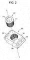
- FIG. 2 illustrates a perspective view of an exemplary embodiment of a mount block member (mount block) 202 and a spacer member (spacer) 204.
- the mount block 202 may be formed from, for example, a metallic material such as steel or another metallic material.
- the mount block 202 includes a body portion 201 and extension portions 203 that extend from opposing sides of the body portion 201.
- the extension portions 203 may include holes 205 that pass through the extension portions 203.
- the body portion 201 defines an orifice 207 having a diameter (d'). In the illustrated embodiment, the orifice 207 has a threaded inner surface 209.
- the spacer 204 includes a threaded outer surface 211 having an approximate diameter d' and a smooth inner surface 213 having an approximate inner diameter d, that corresponds to the diameter d of the mount holes 104 of the pole 100 (of FIG. 1 ).
- the orifice 207 is operative to engage and retain the spacer 204.
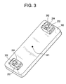
- FIG. 3 illustrates an exemplary embodiment of mount blocks 202 and spacers 204 attached to the pole 100 with fasteners 302.
- the spacer 204 is inserted into the orifice 207 of the mount block 202.
- the inner diameter of the spacer 204 is aligned with the mount hole 104 (of FIG. 1 ) and the assembly is secured with the fastener 302 that is threaded into the mount hole 104.
- the use of the spacer 204 allows the mount block 202 to be used with poles 100 having different sized mount holes 104.
- a spacer 204 having an inner diameter corresponding to the inner diameter of the particular mount hole 104, and a corresponding fastener 302 may be used to secure the mount block 202 to the pole 100.
- the illustrated embodiments include a mount block 202 and spacer 204 arrangement that allows the mount block 202 to be used with a variety of different sized mount holes 104 (by using an appropriately sized spacer 204), alternate embodiments may include a mount block 202 having a smooth bore orifice 207 sized to correspond to the diameter of a particular mount hole 104 without the use of the spacer 204.
- the center of mass of the illustrated embodiment is illustrated by the point 301.
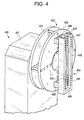
- FIG. 4 illustrates a perspective view of a rotating apparatus 400 and a portion of a mount assembly 404.
- the rotating apparatus 400 includes a stationary portion 401 and a rotating portion 402.
- the rotating portion includes mounting plates 403 that are attached with an arrangement of fasteners.
- the illustrated embodiment includes two mounting plates 403, alternate embodiments may include a single mounting plate 403.
- the mount assembly 404 includes a channel assembly 406 that is attached to the mounting plate 403 with an arrangement of brackets 408 and fasteners (not shown).
- the channel assembly 406 includes opposing side members 405 that define opposing channels 407.
- the channels 407 are sized and shaped to engage the extension portions 203 of the mount blocks 202 (of FIG. 2 ).
- the channel assembly 406 includes a base plate portion 409.
- the base plate portion 409 and side members 405 of the illustrated embodiment are formed from a single, continuous blank material.
- an alternate exemplary embodiment may include a base plate portion 409 that is attached to distal ends of the side members 4
- FIG. 5 illustrates a perspective, partially transparent view of the mount assembly 404 with the pole 100 mounted to the mount assembly 404.
- the extension portions 203 of the mount blocks 202 slidably engage the channels 407 of the channel assembly 406.
- the axis of rotation of the rotating apparatus 400 is indicated by the line 501.
- FIG. 6 illustrates a perspective, partially transparent view of the mount assembly 404.
- the illustrated embodiment includes a cap plate portion 602 that is secured to the channel assembly 406 with fasteners following the mounting of the pole 100 to the mount assembly 404.
- the cap plate portion 602 includes a threaded orifice that engages an alignment member 604.
- the alignment member 604 includes a threaded bolt or stud that engages the cap plate portion 602.
- the alignment member 604 extends through the cap plate portion 602 and contacts the mount block 202.
- the alignment member 604 is adjustable and is operative to exert a force on the mount block 202 along the longitudinal axis of the mount assembly 404.
- FIG. 7 illustrates a perspective, partially transparent view of the mount assembly 404.
- the illustrated embodiment includes an alignment member 604 similar to the alignment member 604 described above that engages the base plate portion 409 and contacts the mount block 202.
- the alignment members 604 exert opposing forces on the mount blocks 202 that retain the position of the mount blocks 202 (and attached pole 100). Since the alignment members 604 are adjustable, they may be adjusted to secure and align the pole 100 with the rotational axis of the rotating apparatus 400 (of FIG. 4 ).
- the mount assembly 404 described above allows poles 100 having a variety of mounting hole arrangements to be mounted to the rotating apparatus 400 with the mount assembly 404 without fabricating a mounting plate for each type of pole 100. While the invention has been described in detail in connection with only a limited number of embodiments, it should be readily understood that the invention is not limited to such disclosed embodiments. Rather, the invention can be modified to incorporate any number of variations, alterations, substitutions or equivalent arrangements not heretofore described, but which are commensurate with the spirit and scope of the invention. Additionally, while various embodiments of the invention have been described, it is to be understood that aspects of the invention may include only some of the described embodiments. Accordingly, the invention is not to be seen as limited by the foregoing description, but is only limited by the scope of the appended claims.
Landscapes
- Engineering & Computer Science (AREA)
- Manufacturing & Machinery (AREA)
- Power Engineering (AREA)
- Connection Of Plates (AREA)
- Supply And Installment Of Electrical Components (AREA)
- Clamps And Clips (AREA)
Abstract
A mounting apparatus includes a channel assembly (406) having side members (405) defining opposing channels (407), a first mount block (202) member slidably engaging the opposing channels (407), a second mount block (202) member slidably engaging the opposing channels (407), a first end member disposed at a first distal end of the channel assembly (406), and a second end member disposed at a second distal end of the channel assembly (406).
Description
- The subject matter disclosed herein relates to electrical machine poles and the winding of electrical machine poles.
- Many electrical machines include poles that include metallic plates wound with wire. The windings on the poles may periodically need to be replaced in a rewinding procedure. A typical rewinding procedure, the poles are removed from the machine, and the windings are removed. The metallic plates may be mounted to a turning apparatus such as, for example, a lathe machine. A wire is attached and wound about the plate by rotating the plate with the turning apparatus.
- The metallic plate of the pole includes mounting holes that are used to mount the pole to the electrical machine. In the rewinding procedure the mounting holes are used to mount the pole to the turning apparatus.
- According to one aspect, the invention resides in a mounting apparatus including a channel assembly having side members defining opposing channels, a first mount block member slidably engaging the opposing channels, a second mount block member slidably engaging the opposing channels, a first end member disposed at a first distal end of the channel assembly, and a second end member disposed at a second distal end of the channel assembly.
- According to another aspect, the invention resides in a method for fabricating an electrical machine component includes connecting a first mounting block to the component, connecting a second mounting block to the component, attaching a channel assembly to a rotating apparatus, and arranging the component such that the first mounting block and the second mounting block slidably engage the channel assembly.
- These and other advantages and features will become more apparent from the following description taken in conjunction with the drawings.
- Embodiments of the present invention will now be described, by way of example only, with reference to the accompanying drawings in which:
-
FIG. 1 illustrates a perspective view of an example of a pole. -
FIG. 2 illustrates a perspective view of an exemplary embodiment of a mount block member and a spacer member. -
FIG. 3 illustrates an exemplary embodiment of mount blocks and spacers attached to the pole ofFIG. 1 . -
FIG. 4 illustrates a perspective view of a rotating apparatus and a portion of a mount assembly. -
FIG. 5 illustrates a perspective, partially transparent view of the mount assembly with the pole mounted to the mount assembly. -
FIG. 6 illustrates a perspective, partially transparent view of the mount assembly. -
FIG. 7 illustrates another perspective, partially transparent view of the mount assembly. - The detailed description explains embodiments of the invention, together with advantages and features, by way of example with reference to the drawings.
- Electrical machines such as, for example, motors and generators often include poles that include metal plates that are wound with wire. The rewinding procedure for a pole includes removing the pole from the electrical machine, and removing the wire from the pole. The metallic plate of the pole includes mounting holes that are often threaded and are operative to mount the pole to the electrical machine. Often a mounting plate is fabricated with holes that match the size and location of the mounting holes in the pole. The pole is attached to the mounting plate, and the mounting plate and pole are secured to a rotating apparatus such as a lathe machine. The rotating apparatus includes a shaft and a fixture or chuck attached to the shaft that is operative to secure objects, such as the mounting plate, to the rotating shaft. A portion of a wire is attached to the metal plate of the pole and the pole is rotated by the rotating apparatus. The wire is wound about the metal plate as the plate rotates forming the rewound pole.
- In a workshop environment, a variety of different types of poles may be rewound. The different types of poles may include metallic plates with mounting holes having a variety of mount hole locations, diameters, and thread pitches. To mount different types of poles on a rotating apparatus, a mounting plate is fabricated with holes that match the mount holes of each type of pole. Thus, for each pole having different mount hole dimensions, a unique mounting plate is fabricated. The illustrated embodiments described below include a mounting apparatus that allows poles having a variety of different mount hole locations, sizes, and thread pitches to be attached to the mounting apparatus that is secured to the rotating apparatus without fabricating a unique mounting plate.
-
FIG. 1 illustrates a perspective view of an example of apole 100. Thepole 100 includes aplate portion 102 andmount holes 104. Themount holes 104 have a diameter (d) and may include a threaded interior surface. -
FIG. 2 illustrates a perspective view of an exemplary embodiment of a mount block member (mount block) 202 and a spacer member (spacer) 204. Themount block 202 may be formed from, for example, a metallic material such as steel or another metallic material. Themount block 202 includes abody portion 201 andextension portions 203 that extend from opposing sides of thebody portion 201. Theextension portions 203 may include holes 205 that pass through theextension portions 203. Thebody portion 201 defines an orifice 207 having a diameter (d'). In the illustrated embodiment, the orifice 207 has a threadedinner surface 209. Thespacer 204 includes a threadedouter surface 211 having an approximate diameter d' and a smoothinner surface 213 having an approximate inner diameter d, that corresponds to the diameter d of themount holes 104 of the pole 100 (ofFIG. 1 ). The orifice 207 is operative to engage and retain thespacer 204. -
FIG. 3 illustrates an exemplary embodiment ofmount blocks 202 andspacers 204 attached to thepole 100 withfasteners 302. In this regard, thespacer 204 is inserted into the orifice 207 of themount block 202. The inner diameter of thespacer 204 is aligned with the mount hole 104 (ofFIG. 1 ) and the assembly is secured with thefastener 302 that is threaded into themount hole 104. The use of thespacer 204 allows themount block 202 to be used withpoles 100 having different sizedmount holes 104. For example, if a similar pole having a different arrangement ofmount holes 104 is used, aspacer 204 having an inner diameter corresponding to the inner diameter of theparticular mount hole 104, and acorresponding fastener 302 may be used to secure themount block 202 to thepole 100. Though the illustrated embodiments include amount block 202 andspacer 204 arrangement that allows themount block 202 to be used with a variety of different sized mount holes 104 (by using an appropriately sized spacer 204), alternate embodiments may include amount block 202 having a smooth bore orifice 207 sized to correspond to the diameter of aparticular mount hole 104 without the use of thespacer 204. The center of mass of the illustrated embodiment is illustrated by thepoint 301. -
FIG. 4 illustrates a perspective view of a rotatingapparatus 400 and a portion of amount assembly 404. In the illustrated embodiment, therotating apparatus 400 includes astationary portion 401 and a rotatingportion 402. The rotating portion includesmounting plates 403 that are attached with an arrangement of fasteners. Though the illustrated embodiment includes twomounting plates 403, alternate embodiments may include asingle mounting plate 403. Themount assembly 404 includes achannel assembly 406 that is attached to themounting plate 403 with an arrangement ofbrackets 408 and fasteners (not shown). Thechannel assembly 406 includesopposing side members 405 that defineopposing channels 407. Thechannels 407 are sized and shaped to engage theextension portions 203 of the mount blocks 202 (ofFIG. 2 ). Thechannel assembly 406 includes abase plate portion 409. Thebase plate portion 409 andside members 405 of the illustrated embodiment are formed from a single, continuous blank material. However, an alternate exemplary embodiment may include abase plate portion 409 that is attached to distal ends of theside members 405 with fasteners (not shown). -
FIG. 5 illustrates a perspective, partially transparent view of themount assembly 404 with thepole 100 mounted to themount assembly 404. In this regard, theextension portions 203 of the mount blocks 202 slidably engage thechannels 407 of thechannel assembly 406. The axis of rotation of therotating apparatus 400 is indicated by theline 501. -
FIG. 6 illustrates a perspective, partially transparent view of themount assembly 404. The illustrated embodiment includes acap plate portion 602 that is secured to thechannel assembly 406 with fasteners following the mounting of thepole 100 to themount assembly 404. Thecap plate portion 602 includes a threaded orifice that engages analignment member 604. In the illustrated embodiment, thealignment member 604 includes a threaded bolt or stud that engages thecap plate portion 602. Thealignment member 604 extends through thecap plate portion 602 and contacts themount block 202. Thealignment member 604 is adjustable and is operative to exert a force on themount block 202 along the longitudinal axis of themount assembly 404. -
FIG. 7 illustrates a perspective, partially transparent view of themount assembly 404. The illustrated embodiment includes analignment member 604 similar to thealignment member 604 described above that engages thebase plate portion 409 and contacts themount block 202. Thealignment members 604 exert opposing forces on the mount blocks 202 that retain the position of the mount blocks 202 (and attached pole 100). Since thealignment members 604 are adjustable, they may be adjusted to secure and align thepole 100 with the rotational axis of the rotating apparatus 400 (ofFIG. 4 ). - The
mount assembly 404 described above allowspoles 100 having a variety of mounting hole arrangements to be mounted to therotating apparatus 400 with themount assembly 404 without fabricating a mounting plate for each type ofpole 100. While the invention has been described in detail in connection with only a limited number of embodiments, it should be readily understood that the invention is not limited to such disclosed embodiments. Rather, the invention can be modified to incorporate any number of variations, alterations, substitutions or equivalent arrangements not heretofore described, but which are commensurate with the spirit and scope of the invention. Additionally, while various embodiments of the invention have been described, it is to be understood that aspects of the invention may include only some of the described embodiments. Accordingly, the invention is not to be seen as limited by the foregoing description, but is only limited by the scope of the appended claims.
Claims (15)
- A mounting apparatus comprising:a channel assembly (406) having side members (405) defining opposing channels (407);a first mount block (202) member slidably engaging the opposing channels (407);a second mount block (202) member slidably engaging the opposing channels (407);a first end member disposed at a first distal end of the channel assembly (406); anda second end member disposed at a second distal end of the channel assembly (406).
- The apparatus of claim 1, wherein the first mount block (202) member and the second mount block (202) member are attached to a component of an electrical machine.
- The apparatus of claim 1 or 2, wherein the first mount block (202) member comprises:a body portion (201);opposing extension portions (203), the extension portions (203) extending from the body portion (201); andan orifice (207) defined by the body portion (201).
- The apparatus of claim 3, wherein the first block member slidably engages the opposing channels (407) with the opposing extension portions (203) of the first mount block (202) member.
- The apparatus of claim 3 or 4, wherein the apparatus further comprises a first spacer (204) portion operative to engage the orifice (207) defined by the body portion (201) to define a spacer (204) orifice (207) having a diameter less than the diameter of the orifice (207) defined by the body portion (201).
- The apparatus of any of claims 3 to 5, wherein the apparatus further comprises:a first fastener (302) passing through the orifice (207) defined by the body portions of the first mount block (202) member, the first fastener (302) engaging a component of an electrical machine; anda second fastener (302) passing through an orifice (207) defined by a body portion (201) of the second block member, the second fastener (302) engaging the component of the electrical machine.
- The apparatus of claim 6, wherein the component of the electrical machine includes a pole (100).
- The apparatus of any preceding claim, wherein the apparatus further comprises:a first alignment member (604) engaging the a first end member;a second alignment member (604) engaging the second end member.
- The apparatus of claim 8, wherein the first alignment member (604) is operative to secure the first mount block (202) member in the channel assembly (406), and the second alignment member (604) is operative to secure the second mount block (202) member in the channel assembly (406).
- The apparatus of claim 8 or 9, wherein the first alignment member (604) includes a fastener (302) operative to engage an orifice (207) in the first end member and contact a surface of the first mount block (202) member.
- The apparatus of any preceding claim, wherein the channel assembly (406) is connected to a rotating apparatus (400).
- A method for fabricating an electrical machine component, the method comprising:connecting a first mounting block (202) to the component;connecting a second mounting block (202) to the component;attaching a channel assembly (406) to a rotating apparatus (400); andarranging the component such that the first mounting block (202) and the second mounting block (202) slidably engage the channel assembly (406).
- The method of claim 12, wherein the method further comprises attaching an end plate to the channel (602) assembly (406).
- The method of claim 12 or 13, wherein the method further comprises aligning the first mounting block (202) and the second mounting block (202) such that a center of gravity of the component is substantially aligned with an axis of rotation of the rotating apparatus (400).
- The method of any of claims 12 to 14, wherein the method further comprises:securing a portion of a wire to the component;starting the rotating apparatus (400); andwinding the wire about a portion of the component.
Applications Claiming Priority (1)
| Application Number | Priority Date | Filing Date | Title |
|---|---|---|---|
| TR2011/03641A TR201103641A2 (en) | 2011-04-14 | 2011-04-14 | Electrical machine component mounting bracket |
Publications (1)
| Publication Number | Publication Date |
|---|---|
| EP2512012A2 true EP2512012A2 (en) | 2012-10-17 |
Family
ID=46049179
Family Applications (1)
| Application Number | Title | Priority Date | Filing Date |
|---|---|---|---|
| EP12163431A Withdrawn EP2512012A2 (en) | 2011-04-14 | 2012-04-05 | Electrical machine component mounting apparatus |
Country Status (4)
| Country | Link |
|---|---|
| US (1) | US20120261534A1 (en) |
| EP (1) | EP2512012A2 (en) |
| CN (1) | CN102738972A (en) |
| TR (1) | TR201103641A2 (en) |
Families Citing this family (1)
| Publication number | Priority date | Publication date | Assignee | Title |
|---|---|---|---|---|
| US11363761B2 (en) * | 2019-01-17 | 2022-06-21 | Robert V. Neuhoff, JR. | Automated hydroponics system |
Family Cites Families (30)
| Publication number | Priority date | Publication date | Assignee | Title |
|---|---|---|---|---|
| US4082324A (en) * | 1976-10-04 | 1978-04-04 | Obrecht Robert E | Connection arrangement for manifold blocks |
| US4097861A (en) * | 1977-03-14 | 1978-06-27 | Pittway Corporation | D.C. horn |
| US4352511A (en) * | 1981-02-17 | 1982-10-05 | Wilkerson Corporation | Releasable clamp for modular connector |
| US4535821A (en) * | 1982-05-19 | 1985-08-20 | John Anderson | Three way valve |
| DE3312536A1 (en) * | 1982-12-03 | 1984-06-07 | Meteor AG, 8803 Rüschlikon | METHOD FOR ANDRILLING WIRE END TO CONTACT PINS |
| US4616788A (en) * | 1985-02-05 | 1986-10-14 | The Globe Tool & Engineering Co. | Method and apparatus for winding dynamoelectric devices |
| US4708297A (en) * | 1985-10-01 | 1987-11-24 | Micafil, Inc. | Armature winding machine with removable collet and shrouds |
| US4773788A (en) * | 1987-05-26 | 1988-09-27 | Kadem Tech. Associates, Ltd. | Safety strap assembly for molds and die cast dies |
| US4830297A (en) * | 1987-11-25 | 1989-05-16 | Statomat-Globe, Inc. | Winding form assembly |
| US4816710A (en) * | 1988-01-22 | 1989-03-28 | Prestolite Electric Incorporated | Field assembly insulator |
| US4975611A (en) * | 1988-11-07 | 1990-12-04 | Rochester D Eugene | Insert sheet for insulating the field winding of an electric motor |
| US5090108A (en) * | 1990-10-17 | 1992-02-25 | Globe Products Inc. | Stator coil winding and lead termination method and apparatus |
| US5413289A (en) * | 1991-07-30 | 1995-05-09 | Axis Usa, Inc. | Programmably controlled armature winding apparatus |
| US5535503A (en) * | 1993-12-03 | 1996-07-16 | Globe Products Inc. | Stator lead wire connection method and apparatus |
| US5560729A (en) * | 1994-01-13 | 1996-10-01 | Bmh Wood Technology, Inc. | Elastomeric joint for a blade tensioning mechanism |
| US5755021A (en) * | 1995-07-07 | 1998-05-26 | Globe Products Inc. | Stator lead wire connecting method |
| DE19622186A1 (en) * | 1996-06-03 | 1997-12-04 | Hilti Ag | Electric motor |
| WO1998021806A2 (en) * | 1996-10-28 | 1998-05-22 | Globe Products Inc. | Stator coil lead termination method and apparatus |
| WO1999054634A1 (en) * | 1998-04-20 | 1999-10-28 | Globe Products, Inc. | Quick-change winding form assembly |
| JP3421251B2 (en) * | 1998-08-21 | 2003-06-30 | ミネベア株式会社 | Rotating electric machine and its bobbin |
| WO2000014855A1 (en) * | 1998-09-04 | 2000-03-16 | Emerson Electric Co. | Reduced size electromagnetic device |
| US6349895B1 (en) * | 1998-11-20 | 2002-02-26 | Axis Usa, Inc. | Changeable flyer |
| WO2001080406A1 (en) * | 2000-04-13 | 2001-10-25 | Globe Products Inc. | Stator winding and coil lead termination method and apparatus |
| US6608409B2 (en) * | 2001-05-15 | 2003-08-19 | General Electric Company | High temperature super-conducting rotor having a vacuum vessel and electromagnetic shield and an assembly method |
| US6617714B2 (en) * | 2001-05-15 | 2003-09-09 | General Electric Company | High temperature super-conducting coils supported by an iron core rotor |
| US6573632B2 (en) * | 2001-07-06 | 2003-06-03 | Chun-Pu Hsu | Structure of a stator forming an annularly closed stable structure |
| ITBS20010067U1 (en) * | 2001-07-18 | 2003-01-18 | Teseo Srl | CONNECTION AND LOCKING DEVICE OF CABLE ELEMENTS FOR THE FORMATION OF FLUID DISTRIBUTION SYSTEMS |
| US7003867B2 (en) * | 2002-10-18 | 2006-02-28 | Asmo Co., Ltd. | Method for winding coils on rotor core |
| US7111380B2 (en) * | 2002-10-31 | 2006-09-26 | Emerson Electric Co. | Method for forming an annular stator assembly |
| US8339011B2 (en) * | 2009-12-07 | 2012-12-25 | Hamilton Sundstrand Corporation | Rotor assembly wire support |
-
2011
- 2011-04-14 TR TR2011/03641A patent/TR201103641A2/en unknown
- 2011-06-15 US US13/161,189 patent/US20120261534A1/en not_active Abandoned
-
2012
- 2012-04-05 EP EP12163431A patent/EP2512012A2/en not_active Withdrawn
- 2012-04-11 CN CN201210114968.8A patent/CN102738972A/en active Pending
Non-Patent Citations (1)
| Title |
|---|
| None |
Also Published As
| Publication number | Publication date |
|---|---|
| CN102738972A (en) | 2012-10-17 |
| US20120261534A1 (en) | 2012-10-18 |
| TR201103641A2 (en) | 2012-11-21 |
Similar Documents
| Publication | Publication Date | Title |
|---|---|---|
| US10084363B2 (en) | Stator assembly method and stator assembly apparatus | |
| JP6185195B2 (en) | Laminated iron core and method for manufacturing the same | |
| US10855150B2 (en) | Method and assembly device for assembling an electric machine | |
| US20130033132A1 (en) | Electric device stator and methods for winding | |
| JP2010158698A (en) | Bending apparatus and bending machine | |
| US20140361500A1 (en) | Expandable arbor, clamping system and method of clamping one of a workpiece and a tool to a machine | |
| CN104904104B (en) | For the bobbin of magnet exciting coil, excitation coil structure, isolation cover, stator apparatus and the stator for homopolar machine | |
| JP2013249953A (en) | Group of temporary fixtures and device for fixing the same | |
| DE102013105498B4 (en) | Fixing device for fixing coils to an electric motor with such a coil fixing device | |
| KR20130124564A (en) | Core winding method and stator | |
| EP2512012A2 (en) | Electrical machine component mounting apparatus | |
| JP6471662B2 (en) | Wire rod holding device | |
| CN105978194A (en) | Motor rotor, permanent magnet motor and assembling method therefor | |
| CN113452221B (en) | Coil inserting device | |
| JP2012190751A (en) | Bindless pin insulator for high voltage | |
| US9161100B2 (en) | Cable tidying device | |
| US20080092357A1 (en) | Method for mounting a thread-protecting element into a receiving thread and mounting spindle and a thread-protecting element therefore | |
| EP2599092B1 (en) | Electric wires twisting device and twisted pair cable fabrication method employing the same | |
| KR20130022180A (en) | Mount member for aluminum profile | |
| JP2014045622A (en) | Winding device of dynamo-electric machine | |
| WO2013031945A1 (en) | Holding apparatus | |
| JP5675750B2 (en) | Battery terminal | |
| KR102041757B1 (en) | Molding jig for manufacturing connector ring of stator | |
| JP6018286B1 (en) | How to install cotter pins and insulators | |
| CN119108207B (en) | A three-dimensional wound core transformer gear mold limiting device |
Legal Events
| Date | Code | Title | Description |
|---|---|---|---|
| PUAI | Public reference made under article 153(3) epc to a published international application that has entered the european phase |
Free format text: ORIGINAL CODE: 0009012 |
|
| AK | Designated contracting states |
Kind code of ref document: A2 Designated state(s): AL AT BE BG CH CY CZ DE DK EE ES FI FR GB GR HR HU IE IS IT LI LT LU LV MC MK MT NL NO PL PT RO RS SE SI SK SM TR |
|
| AX | Request for extension of the european patent |
Extension state: BA ME |
|
| STAA | Information on the status of an ep patent application or granted ep patent |
Free format text: STATUS: THE APPLICATION IS DEEMED TO BE WITHDRAWN |
|
| 18D | Application deemed to be withdrawn |
Effective date: 20141101 |