EP2511630A1 - Air conditioner and refrigerant amount detection method for air conditioner - Google Patents
Air conditioner and refrigerant amount detection method for air conditioner Download PDFInfo
- Publication number
- EP2511630A1 EP2511630A1 EP10835875A EP10835875A EP2511630A1 EP 2511630 A1 EP2511630 A1 EP 2511630A1 EP 10835875 A EP10835875 A EP 10835875A EP 10835875 A EP10835875 A EP 10835875A EP 2511630 A1 EP2511630 A1 EP 2511630A1
- Authority
- EP
- European Patent Office
- Prior art keywords
- refrigerant
- circuit
- liquid level
- temperature
- level detecting
- Prior art date
- Legal status (The legal status is an assumption and is not a legal conclusion. Google has not performed a legal analysis and makes no representation as to the accuracy of the status listed.)
- Granted
Links
Images


Classifications
-
- F—MECHANICAL ENGINEERING; LIGHTING; HEATING; WEAPONS; BLASTING
- F25—REFRIGERATION OR COOLING; COMBINED HEATING AND REFRIGERATION SYSTEMS; HEAT PUMP SYSTEMS; MANUFACTURE OR STORAGE OF ICE; LIQUEFACTION SOLIDIFICATION OF GASES
- F25B—REFRIGERATION MACHINES, PLANTS OR SYSTEMS; COMBINED HEATING AND REFRIGERATION SYSTEMS; HEAT PUMP SYSTEMS
- F25B49/00—Arrangement or mounting of control or safety devices
- F25B49/005—Arrangement or mounting of control or safety devices of safety devices
-
- F—MECHANICAL ENGINEERING; LIGHTING; HEATING; WEAPONS; BLASTING
- F25—REFRIGERATION OR COOLING; COMBINED HEATING AND REFRIGERATION SYSTEMS; HEAT PUMP SYSTEMS; MANUFACTURE OR STORAGE OF ICE; LIQUEFACTION SOLIDIFICATION OF GASES
- F25B—REFRIGERATION MACHINES, PLANTS OR SYSTEMS; COMBINED HEATING AND REFRIGERATION SYSTEMS; HEAT PUMP SYSTEMS
- F25B40/00—Subcoolers, desuperheaters or superheaters
- F25B40/02—Subcoolers
-
- F—MECHANICAL ENGINEERING; LIGHTING; HEATING; WEAPONS; BLASTING
- F25—REFRIGERATION OR COOLING; COMBINED HEATING AND REFRIGERATION SYSTEMS; HEAT PUMP SYSTEMS; MANUFACTURE OR STORAGE OF ICE; LIQUEFACTION SOLIDIFICATION OF GASES
- F25B—REFRIGERATION MACHINES, PLANTS OR SYSTEMS; COMBINED HEATING AND REFRIGERATION SYSTEMS; HEAT PUMP SYSTEMS
- F25B40/00—Subcoolers, desuperheaters or superheaters
- F25B40/06—Superheaters
-
- F—MECHANICAL ENGINEERING; LIGHTING; HEATING; WEAPONS; BLASTING
- F25—REFRIGERATION OR COOLING; COMBINED HEATING AND REFRIGERATION SYSTEMS; HEAT PUMP SYSTEMS; MANUFACTURE OR STORAGE OF ICE; LIQUEFACTION SOLIDIFICATION OF GASES
- F25B—REFRIGERATION MACHINES, PLANTS OR SYSTEMS; COMBINED HEATING AND REFRIGERATION SYSTEMS; HEAT PUMP SYSTEMS
- F25B45/00—Arrangements for charging or discharging refrigerant
-
- F—MECHANICAL ENGINEERING; LIGHTING; HEATING; WEAPONS; BLASTING
- F25—REFRIGERATION OR COOLING; COMBINED HEATING AND REFRIGERATION SYSTEMS; HEAT PUMP SYSTEMS; MANUFACTURE OR STORAGE OF ICE; LIQUEFACTION SOLIDIFICATION OF GASES
- F25B—REFRIGERATION MACHINES, PLANTS OR SYSTEMS; COMBINED HEATING AND REFRIGERATION SYSTEMS; HEAT PUMP SYSTEMS
- F25B49/00—Arrangement or mounting of control or safety devices
- F25B49/02—Arrangement or mounting of control or safety devices for compression type machines, plants or systems
-
- F—MECHANICAL ENGINEERING; LIGHTING; HEATING; WEAPONS; BLASTING
- F25—REFRIGERATION OR COOLING; COMBINED HEATING AND REFRIGERATION SYSTEMS; HEAT PUMP SYSTEMS; MANUFACTURE OR STORAGE OF ICE; LIQUEFACTION SOLIDIFICATION OF GASES
- F25B—REFRIGERATION MACHINES, PLANTS OR SYSTEMS; COMBINED HEATING AND REFRIGERATION SYSTEMS; HEAT PUMP SYSTEMS
- F25B2345/00—Details for charging or discharging refrigerants; Service stations therefor
- F25B2345/003—Control issues for charging or collecting refrigerant to or from a cycle
-
- F—MECHANICAL ENGINEERING; LIGHTING; HEATING; WEAPONS; BLASTING
- F25—REFRIGERATION OR COOLING; COMBINED HEATING AND REFRIGERATION SYSTEMS; HEAT PUMP SYSTEMS; MANUFACTURE OR STORAGE OF ICE; LIQUEFACTION SOLIDIFICATION OF GASES
- F25B—REFRIGERATION MACHINES, PLANTS OR SYSTEMS; COMBINED HEATING AND REFRIGERATION SYSTEMS; HEAT PUMP SYSTEMS
- F25B2345/00—Details for charging or discharging refrigerants; Service stations therefor
- F25B2345/007—Details for charging or discharging refrigerants; Service stations therefor characterised by the weighing of refrigerant or oil
-
- F—MECHANICAL ENGINEERING; LIGHTING; HEATING; WEAPONS; BLASTING
- F25—REFRIGERATION OR COOLING; COMBINED HEATING AND REFRIGERATION SYSTEMS; HEAT PUMP SYSTEMS; MANUFACTURE OR STORAGE OF ICE; LIQUEFACTION SOLIDIFICATION OF GASES
- F25B—REFRIGERATION MACHINES, PLANTS OR SYSTEMS; COMBINED HEATING AND REFRIGERATION SYSTEMS; HEAT PUMP SYSTEMS
- F25B2400/00—General features or devices for refrigeration machines, plants or systems, combined heating and refrigeration systems or heat-pump systems, i.e. not limited to a particular subgroup of F25B
- F25B2400/13—Economisers
-
- F—MECHANICAL ENGINEERING; LIGHTING; HEATING; WEAPONS; BLASTING
- F25—REFRIGERATION OR COOLING; COMBINED HEATING AND REFRIGERATION SYSTEMS; HEAT PUMP SYSTEMS; MANUFACTURE OR STORAGE OF ICE; LIQUEFACTION SOLIDIFICATION OF GASES
- F25B—REFRIGERATION MACHINES, PLANTS OR SYSTEMS; COMBINED HEATING AND REFRIGERATION SYSTEMS; HEAT PUMP SYSTEMS
- F25B2400/00—General features or devices for refrigeration machines, plants or systems, combined heating and refrigeration systems or heat-pump systems, i.e. not limited to a particular subgroup of F25B
- F25B2400/16—Receivers
-
- F—MECHANICAL ENGINEERING; LIGHTING; HEATING; WEAPONS; BLASTING
- F25—REFRIGERATION OR COOLING; COMBINED HEATING AND REFRIGERATION SYSTEMS; HEAT PUMP SYSTEMS; MANUFACTURE OR STORAGE OF ICE; LIQUEFACTION SOLIDIFICATION OF GASES
- F25B—REFRIGERATION MACHINES, PLANTS OR SYSTEMS; COMBINED HEATING AND REFRIGERATION SYSTEMS; HEAT PUMP SYSTEMS
- F25B2600/00—Control issues
- F25B2600/05—Refrigerant levels
-
- F—MECHANICAL ENGINEERING; LIGHTING; HEATING; WEAPONS; BLASTING
- F25—REFRIGERATION OR COOLING; COMBINED HEATING AND REFRIGERATION SYSTEMS; HEAT PUMP SYSTEMS; MANUFACTURE OR STORAGE OF ICE; LIQUEFACTION SOLIDIFICATION OF GASES
- F25B—REFRIGERATION MACHINES, PLANTS OR SYSTEMS; COMBINED HEATING AND REFRIGERATION SYSTEMS; HEAT PUMP SYSTEMS
- F25B2700/00—Sensing or detecting of parameters; Sensors therefor
- F25B2700/04—Refrigerant level
Definitions
- the present invention relates to an air conditioner in which an optimal amount of refrigerant can always be filled at a time of installation, and a refrigerant amount detection method for an air conditioner.
- a multi-type air conditioner that is used for air-conditioning a building or the like has a configuration in which an outdoor unit that includes a compressor, a four-way switching valve, an outdoor heat exchanger, a heating expansion valve, a receiver, and an outdoor fan and the like, and a plurality of indoor units that include an indoor heat exchanger, a cooling expansion valve, and an indoor fan and the like, are connected at the installation site by gas refrigerant piping and liquid refrigerant piping.
- a predetermined amount of refrigerant is filled in advance into the outdoor unit, and when performing a test operation after installing the air conditioner at the installation site, refrigerant of an amount that corresponds to an insufficient amount of refrigerant in accordance with the length of piping that connects the outdoor unit and indoor units, the number of indoor units that are connected and the like, is additionally filled into the outdoor unit.
- Patent Literature 1 hereunder abbreviated as "PTL 1" ⁇ and Patent Literature 2 (hereunder abbreviated as “PTL 2”) disclose technology configured to determine that a required amount of refrigerant is filled in a refrigerant circuit so that a filling amount of refrigerant that is additionally added to an outdoor unit need not depend on operations at the construction work level at the installation site.
- a liquid level detecting circuit is provided that, when performing refrigerant filling operation, detects that a liquid refrigerant that is being accumulated inside a receiver in a refrigerant circuit has reached a predetermined liquid level.
- PTL 1 discloses technology in which a bypass circuit that includes an on/off valve, a decompression mechanism, and a temperature detecting unit is connected to a compressor intake side from a predetermined height position of a receiver.
- PTL 2 discloses technology in which an on/off valve, a decompression mechanism, heating means and a temperature detecting unit are provided in a bypass circuit.
- the temperature of a refrigerant after decompression is measured in a case where gas refrigerant in a saturated state is taken out from the receiver to the bypass circuit and a case where liquid refrigerant in a saturated state is taken out from the receiver to the bypass circuit, respectively, and a refrigerant amount is determined by detecting that liquid refrigerant of a predetermined liquid level is accumulated in the receiver based on a temperature difference between the two measured temperatures.
- a configuration is adopted that attempts to improve detection accuracy by providing heating means that heats refrigerant that has been decompressed by a decompression mechanism in a liquid level detecting circuit.
- a temperature difference can be adequately ensured by utilizing a fact that when refrigerant taken out from a receiver is in a gaseous state, an increase in the temperature thereof produced by heating is large, while when refrigerant taken out from a receiver is in a liquid state, thermal energy produced by heating is consumed as latent heat of vaporization and an increase in the temperature thereof is small.
- it is essential to provide heating means in the liquid level detecting circuit there is the problem that the configuration is complicated.
- the present invention has been made in view of the above described circumstances, and an object of the present invention is to provide an air conditioner and a refrigerant amount detection method for an air conditioner which can always detect a refrigerant filling amount with high accuracy even under a condition of a low outside air temperature, without specially providing heating means in a liquid level detecting circuit.
- an air conditioner according to a first aspect of the present invention constitutes a closed-cycle refrigerant circuit in which an outdoor unit that includes a compressor, an outdoor heat exchanger, a heating expansion valve, a receiver that stores a liquid refrigerant, and a supercooling circuit that, after diverting a flow of one part of a liquid refrigerant and decompressing the refrigerant by means of a decompression mechanism, causes the refrigerant to exchange heat with a liquid refrigerant at a supercooling heat exchanger and returns the refrigerant to an intake side of the compressor and the like, and an indoor unit that includes an indoor heat exchanger and a cooling expansion valve and the like are connected by gas refrigerant piping and liquid refrigerant piping; the air conditioner including: a first liquid level detecting circuit in which an on/off valve and a decompression mechanism are inter
- the air conditioner according to the first aspect includes: a first liquid level detecting circuit in which an on/off valve and a decompression mechanism are interposed in a bypass circuit that connects a predetermined height position of a receiver and an intake side of a compressor via a supercooling circuit; a second liquid level detecting circuit that is branched from the bypass circuit and in which an on/off valve is interposed that acts as a bypass for leading a refrigerant that is taken out from the receiver to an inlet side of a decompression mechanism of the supercooling circuit; a temperature detecting unit that detects a temperature of decompressed refrigerant that passes through the supercooling circuit including the first liquid level detecting circuit or the second liquid level detecting circuit; and a refrigerant amount detecting unit that detects, by means of the temperature detecting unit, a temperature after decompression of a refrigerant that is taken out from the receiver via the first liquid level detecting circuit or the second liquid level detecting circuit, and determines a refrigerant fill
- the above described temperature difference can be sufficiently ensured under a wide range of temperature conditions without being influenced by fluctuations in a high pressure caused by an outside air temperature or the like, and a refrigerant filling amount can be detected with high accuracy. It is therefore possible to fill an optimum amount of refrigerant that is neither excessive nor insufficient to enable stable operation of the air conditioner. Further, since refrigerant can be heated utilizing the supercooling circuit, it is not necessary to specially provide heating means on the first liquid level detecting circuit side, and thus the configuration can be simplified.
- An air conditioner according to a second aspect of the present invention is in accordance with the above described air conditioner, wherein an electromagnetic on/off valve that is closed at a time of refrigerant filling operation and is opened at a time of normal cooling or heating operation is provided in a vicinity of a branch portion from the refrigerant circuit of the supercooling circuit.
- the air conditioner according to the second aspect is provided with an electromagnetic on/off valve that is closed at a time of refrigerant filling operation and is opened at a time of normal cooling or heating operation in a vicinity of a branch portion from the refrigerant circuit of the supercooling circuit, switching between refrigerant filling operation and normal cooling or heating operation can be simply carried out by only performing an operation to open or close the electromagnetic on/off valve. Therefore, in addition to enhancing the capacity at a time of normal operation, the supercooling circuit is also used as a liquid level detecting circuit at a time of refrigerant filling operation, and can contribute to improving the accuracy of detecting a refrigerant filling amount.
- An air conditioner constitutes a closed-cycle refrigerant circuit in which an outdoor unit that includes a compressor, an outdoor heat exchanger, a heating expansion valve, and a receiver that stores a liquid refrigerant and the like, and an indoor unit that includes an indoor heat exchanger and a cooling expansion valve and the like are connected by gas refrigerant piping and liquid refrigerant piping;
- the air conditioner including: a liquid level detecting circuit in which an on/off valve and a decompression mechanism are interposed in a bypass circuit that connects a predetermined height position of the receiver and an intake side of the compressor; a hot gas bypass circuit including an on/off valve and a decompression mechanism that is capable of introducing a portion of a hot gas from a discharge side of the compressor to the intake side thereof; a temperature detecting unit that is capable of detecting a temperature of a refrigerant that passes through the liquid level detecting circuit or a refrigerant in which the refrigerant that passes through the liquid
- the air conditioner according to the third aspect includes: a liquid level detecting circuit in which an on/off valve and a decompression mechanism are interposed in a bypass circuit that connects a predetermined height position of a receiver and an intake side of a compressor; a hot gas bypass circuit that includes an on/off valve and a decompression mechanism that is capable of introducing a portion of a hot gas from a discharge side of the compressor to the intake side thereof; a temperature detecting unit that is capable of detecting a temperature of a refrigerant that passes through the liquid level detecting circuit or a refrigerant in which the refrigerant that passes through the liquid level detecting circuit and a hot gas that is introduced via the hot gas bypass circuit are mixed; and a refrigerant amount detecting unit that detects, by means of the temperature detecting unit, a temperature after decompression of a refrigerant that is taken out from the receiver to the liquid level detecting circuit or of a mixed refrigerant composed of the refrigerant that is taken out from the
- a refrigerant temperature after decompression can be detected in a case where a gas refrigerant in a saturated state is taken out from the receiver to the liquid level detecting circuit and a case where a saturated liquid refrigerant is taken out from the receiver to the liquid level detecting circuit, respectively, and it is possible to detect that liquid refrigerant of a predetermined liquid level is accumulated in the receiver based on a temperature difference between the two detected refrigerant temperatures.
- the degree of superheat can be sufficiently ensured by heating the saturated gas refrigerant that is taken out from the receiver by mixing the gas refrigerant with a hot gas that is introduced via the hot gas bypass circuit, it is possible to detect that liquid refrigerant of a predetermined liquid level is accumulated in the receiver based on a temperature difference between such a case and a case where a saturated liquid refrigerant is taken out. Accordingly, the above described temperature difference can be sufficiently ensured under a wide range of temperature conditions without being influenced by fluctuations in a high pressure caused by an outside air temperature or the like, and a refrigerant filling amount can be detected with high accuracy. It is therefore possible to fill an optimum amount of refrigerant that is neither excessive nor insufficient to enable stable operation of the air conditioner.
- a refrigerant amount detection method for an air conditioner is a refrigerant amount detection method for the above described air conditioner that, at a time of refrigerant filling operation, under a temperature condition of a cooling rating extent, performs liquid-level detection by closing the second liquid level detecting circuit by means of the on/off valve and using the first liquid level detecting circuit, and under a condition of a low outside air temperature, performs liquid-level detection by closing the first liquid level detecting circuit by means of the on/off valve and using the second liquid level detecting circuit.
- detection of a liquid level is performed by closing the second liquid level detecting circuit by means of the on/off valve and using the first liquid level detecting circuit, and under a condition of a low outside air temperature, detection of a liquid level is performed by closing the first liquid level detecting circuit by means of the on/off valve and using the second liquid level detecting circuit.
- a refrigerant amount detection method for an air conditioner is a refrigerant amount detection method for the above described air conditioner that, at a time of refrigerant filling operation, performs liquid-level detection under a temperature condition of a cooling rating extent by using only the liquid level detecting circuit, and performs liquid-level detection under a condition of a low outside air temperature by using both the liquid level detecting circuit and the hot gas bypass circuit.
- detection of a liquid level is performed using only the liquid level detecting circuit under a temperature condition of a cooling rating extent, and is performed using both the liquid level detecting circuit and the hot gas bypass circuit under a condition of a low outside air temperature.
- liquid level detecting circuit or the liquid level detecting circuit and the hot gas bypass circuit it is possible to detect under a wide range of temperature conditions that liquid refrigerant of a predetermined liquid level is accumulated in the receiver based on a temperature difference between a case where a saturated gas refrigerant is taken out from the receiver and a case where a saturated liquid refrigerant is taken out from the receiver, and thus a refrigerant filling amount can be detected with high accuracy. Accordingly, it is possible to fill an optimum amount of refrigerant that is neither excessive nor insufficient into the air conditioner.
- the air conditioner and the refrigerant amount detection method for an air conditioner of the present invention under a temperature condition of a cooling rating extent, by allowing a refrigerant to flow from the receiver into the first liquid level detecting circuit and detecting a refrigerant temperature after decompression in a case where a saturated gas refrigerant is taken out from the receiver and a case where a saturated liquid refrigerant is taken out from the receiver, respectively, it is possible to reliably detect that liquid refrigerant of a predetermined liquid level is accumulated in the receiver based on a temperature difference between the two detected refrigerant temperatures.
- the above described temperature difference can be sufficiently ensured under a wide range of temperature conditions without being influenced by fluctuations in a high pressure caused by an outside air temperature or the like, and a refrigerant filling amount can be detected with high accuracy. It is therefore possible to fill an optimum amount of refrigerant that is neither excessive nor insufficient to enable stable operation of the air conditioner. Further, since refrigerant can be heated utilizing the supercooling circuit, it is not necessary to specially provide heating means on the first liquid level detecting circuit side, and thus the configuration can be simplified.
- a refrigerant temperature after decompression can be detected in a case where a gas refrigerant in a saturated state is taken out from the receiver to the liquid level detecting circuit and a case where a saturated liquid refrigerant is taken out from the receiver to the liquid level detecting circuit, respectively, and it is possible to detect that liquid refrigerant of a predetermined liquid level is accumulated in the receiver based on a temperature difference between the two detected refrigerant temperatures.
- the degree of superheat can be sufficiently increased by heating the saturated gas refrigerant that is taken out from the receiver by mixing the gas refrigerant with a hot gas that is introduced via the hot gas bypass circuit, it is possible to detect that liquid refrigerant of a predetermined liquid level is accumulated in the receiver based on a temperature difference between such a case and a case where a saturated liquid refrigerant is taken out. Accordingly, the above described temperature difference can be sufficiently ensured under a wide range of temperature conditions without being influenced by fluctuations in a high pressure caused by an outside air temperature or the like, and a refrigerant filling amount can be detected with high accuracy. It is therefore possible to fill an optimum amount of refrigerant that is neither excessive nor insufficient to enable stable operation of the air conditioner.
- FIG. 1 is a refrigerant circuit diagram of an air conditioner according to the first embodiment of the present invention.
- An air conditioner 1 is a multi-type air conditioner that is used to air condition a building or the like.
- the air conditioner 1 includes an outdoor unit 2 and a plurality of indoor units 3 that are connected to each other in parallel (only one indoor unit 3 is shown in Fig. 1 ).
- the outdoor unit 2 includes a compressor 10 that compresses a refrigerant, a four-way switching valve 11 that switches a circulation direction of a refrigerant, an outdoor heat exchanger 12 that causes a heat exchange to take place between outside air and a refrigerant, an outdoor fan 13 that causes outside air to flow through the outdoor heat exchanger 12, a motor-operated expansion valve for heating (heating expansion valve) 14, and a receiver 15 that accumulates condensed liquid refrigerant.
- An outdoor-side refrigerant circuit 17 is constituted by connecting the compressor 10, the four-way switching valve 11, the outdoor heat exchanger 12, the motor-operated expansion valve for heating 14, and the receiver 15 in sequence through refrigerant piping 16.
- the refrigerant circuit 17 is provided with a supercooling circuit 20 configured to carry out supercooling of a liquid refrigerant in a supercooling heat exchanger 19 by diverting one portion of the liquid refrigerant, and after decompressing the liquid refrigerant using a supercooling expansion valve (decompression mechanism) 18, returning the liquid refrigerant to an intake side of the compressor 10 via the supercooling heat exchanger 19.
- a supercooling circuit 20 configured to carry out supercooling of a liquid refrigerant in a supercooling heat exchanger 19 by diverting one portion of the liquid refrigerant, and after decompressing the liquid refrigerant using a supercooling expansion valve (decompression mechanism) 18, returning the liquid refrigerant to an intake side of the compressor 10 via the supercooling heat exchanger 19.
- An indoor heat exchanger 30, an indoor fan 31 that causes indoor air to circulate through the indoor heat exchanger 30, a motor-operated expansion valve for cooling (cooling expansion valve) 32 and the like are arranged inside the indoor unit 3.
- the indoor unit 3 and the outdoor unit 2 are connected through gas refrigerant piping 33 and liquid refrigerant piping 34 to thereby constitute a closed-cycle refrigerant circuit 35.
- a plurality of the indoor units 3 are connected in parallel through gas refrigerant piping 33 and liquid refrigerant piping 34 that branches from the gas refrigerant piping 33 and the liquid refrigerant piping 34.
- the air conditioner 1 is configured to be capable of performing cooling operation by causing the outdoor heat exchanger 12 to function as a condenser and causing the indoor heat exchanger 30 to function as an evaporator.
- the air conditioner 1 causes a refrigerant that has been discharged from the compressor 10 to circulate to the outdoor heat exchanger 12 side through the four-way switching valve 11, and causes the refrigerant to circulate in a clockwise direction in the order of the receiver 15, the supercooling heat exchanger 19, the motor-operated expansion valve for cooling 32, the indoor heat exchanger 30, the four-way switching valve 11, and the compressor 10.
- the cooling capacity can be improved by diverting liquid refrigerant to the supercooling circuit 20 at the supercooling heat exchanger 19, and causing the liquid refrigerant to exchange heat with decompressed refrigerant at the supercooling expansion valve (decompression mechanism) 18 to thereby supercool the liquid refrigerant.
- the air conditioner 1 is configured to be also capable of performing heating operation by causing the indoor heat exchanger 30 to function as a condenser and causing the outdoor heat exchanger 12 to function as an evaporator.
- the air conditioner 1 causes a refrigerant that has been discharged from the compressor 10 to circulate to the indoor heat exchanger 30 side through the four-way switching valve 11, and causes the refrigerant to circulate in a counterclockwise direction in the order of the supercooling heat exchanger 19, the receiver 15, motor-operated expansion valve for heating 14, the outdoor heat exchanger 12, the four-way switching valve 11, and the compressor 10.
- the length of the gas refrigerant piping 33 and the liquid refrigerant piping 34 that connects the outdoor unit 2 and each indoor unit 3 changes variously according to the environment in which the air conditioner 1 is installed. Consequently, a predetermined amount of refrigerant is filled in advance in the outdoor unit 2, and when performing a test operation after installing the air conditioner 1 at the installation site, it is necessary to additionally fill an amount that corresponds to an insufficient amount of refrigerant in accordance with the length of piping that connects the outdoor unit 2 and the indoor units 3 as well as the number of indoor units 3 that are connected and the like.
- a first liquid level detecting circuit 40, a second liquid level detecting circuit 45, and a refrigerant amount detecting unit 48 are incorporated into the air conditioner 1.
- the first liquid level detecting circuit 40 includes: a bypass circuit 41 that can take a refrigerant out from a predetermined height position in the receiver 15 to an intake side of the compressor 10; and a decompression mechanism 42 that is composed of a capillary tube or an expansion valve or the like and an electromagnetic on/off valve 43 that are provided in the bypass circuit 41.
- the bypass circuit 41 is connected to and merged with the supercooling circuit 20 in a vicinity of a connecting portion at which the supercooling circuit 20 is connected to intake piping of the compressor 10.
- a temperature sensor (temperature detecting unit) 44 such as a thermistor is arranged at a position that is further on the intake piping side of the compressor 10 than the connecting and merging portion of the bypass circuit 41.
- the temperature sensor 44 detects a temperature of a refrigerant that has been decompressed at the decompression mechanism 42 or the decompression mechanism 18 and that flows inside the bypass circuit 41 and the supercooling circuit 20.
- the second liquid level detecting circuit 45 branches from a position that is located before the decompression mechanism 42 in the bypass circuit 41 constituting the first liquid level detecting circuit 40, and includes an electromagnetic on/off valve 46 that is provided in a circuit that is connected to an inlet side of the supercooling expansion valve (decompression mechanism) 18 of the supercooling circuit 20.
- the second liquid level detecting circuit 45 constitutes a circuit that, when carrying out refrigerant filling operation, returns refrigerant that has been taken out from the receiver 15 to the intake side of the compressor 10 via the supercooling expansion valve (decompression mechanism) 18 and the supercooling heat exchanger 19 in the supercooling circuit 20.
- An electromagnetic on/off valve 47 is provided close to a branch portion of the supercooling circuit 20 in order to stop the flow of liquid refrigerant diverging to the supercooling circuit 20 at such time.
- the refrigerant amount detecting unit 48 is provided to determine whether or not an appropriate amount of a refrigerant has been filled based on a detection temperature of the temperature sensor 44.
- the refrigerant amount detecting unit 48 is configured to be able to determine, during refrigerant filling operation, whether or not an appropriate amount of refrigerant has been filled based on a temperature difference between a detection temperature from the temperature sensor 44 in a case where liquid refrigerant accumulates in the receiver 15 and the liquid level thereof reaches a height position at which the bypass circuit 31 opens and liquid refrigerant in a saturated state is taken out to the first liquid level detecting circuit 40 or the second liquid level detecting circuit 45, and a detection temperature from the temperature sensor 44 in a case where a gas refrigerant in a saturated state is taken out to the first liquid level detecting circuit 40 or the second liquid level detecting circuit 45 during a period until the liquid refrigerant reaches a predetermined height position.
- the refrigerant amount detecting unit 48 has a function that closes the electromagnetic on/off valve 47 provided in the supercooling circuit 20 when performing refrigerant filling operation, and also performs opening/closing control of the electromagnetic on/off valves 43 and 46 when determining whether to perform liquid-level detection using either the first liquid level detecting circuit 40 or the second liquid level detecting circuit 45 in accordance with an outside air temperature or a high-pressure side pressure or the like.
- the refrigerant amount detecting unit 48 opens the electromagnetic on/off valve 43 and closes the electromagnetic on/off valve 46, and when using the second liquid level detecting circuit 45, the refrigerant amount detecting unit 48 closes the electromagnetic on/off valve 43 and opens the electromagnetic on/off valve 46.
- Refrigerant filling operation is performed by operating the refrigerant circuit 35 as a cooling cycle.
- the outdoor fan 13 is controlled so that a condensing pressure at the outdoor heat exchanger 12 becomes a predetermined value, and a degree of opening of the motor-operated expansion valve for cooling 32 is controlled so that a predetermined degree of superheat is applied to refrigerant at an outlet of the indoor heat exchanger 30.
- a refrigerant can be filled into the refrigerant circuit 35 as a state in which a liquid refrigerant of a predetermined density is filled inside the liquid refrigerant piping 34.
- the electromagnetic on/off valve 47 in the supercooling circuit 20 is closed and, for example, when the outside air temperature is a high temperature of a cooling rating extent, the electromagnetic on/off valve 43 is opened and the electromagnetic on/off valve 46 is closed, while, in contrast, when the outside air temperature is low, the electromagnetic on/off valve 43 is closed and the electromagnetic on/off valve 46 is opened.
- the circulating amount of refrigerant in the refrigerant circuit 35 is gradually increased, and the liquid level of refrigerant in the receiver 15 gradually rises.
- the saturated gas refrigerant and the saturated liquid refrigerant are respectively decompressed into a decompressed state by the decompression mechanism 43.
- the refrigerant amount detecting unit 48 can detect that liquid refrigerant of a predetermined liquid level has been accumulated in the receiver 15 by observing a temperature difference between a case where the temperature has dropped from a state of a saturated gas refrigerant and a case where the temperature has dropped from a state of a saturated liquid refrigerant.
- the refrigerant amount detecting unit 48 determines that refrigerant of a required amount has been filled, and at that time the refrigerant filling operation is ended.
- a configuration is adopted such that, when a slope of a saturated gas line ascends diagonally from the lower left to the upper right on a pressure-enthalpy diagram at a time of a low outside air temperature at which the high pressure falls, the refrigerant taken out from the receiver 15 is caused to flow to the supercooling circuit 20 via the second liquid level detecting circuit 45 by switching the liquid level detecting circuit to the second liquid level detecting circuit 45 by closing the electromagnetic on/off valve 43 and opening the electromagnetic on/off valve 46.
- the refrigerant that is taken out to the supercooling circuit 20 via the second liquid level detecting circuit 45 is decompressed by the supercooling expansion valve (decompression mechanism) 18, and thereafter is heated by exchanging heat with liquid refrigerant at the supercooling heat exchanger 19 and evaporates, and is returned to the intake side of the compressor 10.
- a temperature difference of a fixed value or more between a case where a saturated gas refrigerant is taken out and a case where a saturated liquid refrigerant is taken out can be ensured. That is, as shown in Fig. 5 , after the saturated liquid refrigerant is decompressed at the decompression mechanism 18 and the temperature thereof falls, the refrigerant is heated at the supercooling heat exchanger 19 and evaporated, and becomes a refrigerant that has a degree of superheat as 0 °C at a point D on the saturated gas line.
- the degree of superheat SH is increased as far as a point E by heating the refrigerant at the supercooling heat exchanger 19. Consequently, a temperature difference can be adequately ensured, and the refrigerant amount detecting unit 48 can reliably detect that refrigerant of an appropriate amount has been filled.
- a temperature difference between a saturated gas refrigerant and a saturated liquid refrigerant can be adequately ensured under a wide range of temperature conditions without being influenced by fluctuations in a high pressure caused by an outside air temperature or the like and a refrigerant filling amount can be detected with high accuracy.
- a refrigerant filling amount can be detected with high accuracy.
- refrigerant can be heated utilizing the supercooling circuit 20, it is not necessary to specially provide heating means on the first liquid level detecting circuit 40 side, and hence the configuration can be simplified.
- the electromagnetic on/off valve 47 that is closed when performing refrigerant filling operation and opened when performing normal cooling or heating operation is provided in the vicinity of a branch portion from the refrigerant circuit 35 of the supercooling circuit 20. It is therefore possible to easily perform switching between refrigerant filling operation and normal cooling or heating operation by performing only an operation to open or close the electromagnetic on/off valve 47. Accordingly, in addition to enhancing the capacity at a time of normal cooling or heating operation, the supercooling circuit 20 is also used as a liquid level detecting circuit at a time of refrigerant filling operation, and can contribute to improving the accuracy of detecting a refrigerant filling amount. Further, since an existing temperature sensor provided in the supercooling circuit 20 can be used in a shared manner as the temperature sensor 44, a saving can be made with respect to the provision of a temperature sensor.
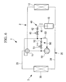
- a second embodiment of the present invention is described using Fig. 6 to Fig. 8 .
- the configuration of the present embodiment differs from the first embodiment in that a hot gas bypass circuit 50 is provided instead of the second liquid level detecting circuit 45. Since the remaining configuration is the same as the first embodiment, a description thereof is omitted below. According to the present embodiment, as shown in Fig.
- a configuration is adopted that includes: a liquid level detecting circuit 40 in which, similarly to the above described first liquid level detecting circuit 40, the decompression mechanism 42 constituted by a capillary tube or an expansion valve or the like and the electromagnetic on/off valve 43 are interposed in the bypass circuit 41 that connects a predetermined height position inside the receiver 15 and the intake side of the compressor 10; the hot gas bypass circuit 50 that includes an electromagnetic on/off valve 51 and a decompression mechanism 52 constituted by a capillary tube or an expansion valve or the like and that can introduce a portion of hot gas from a discharge side of the compressor 10 to an intake side thereof; and a temperature sensor 53 that detects a temperature of a refrigerant that has passed through the liquid level detecting circuit 40 or of a mixed refrigerant of a refrigerant that has passed through the liquid level detecting circuit 40 and a hot gas that is introduced by the hot gas bypass circuit 50.
- the refrigerant amount detecting unit 48 is configured to be able to determine a refrigerant filling amount by detecting that liquid refrigerant of a predetermined liquid level has accumulated in the receiver 15 based on a detection value from the temperature sensor 53. Further, the refrigerant amount detecting unit 48 has a function that, at a time of refrigerant filling operation, controls opening and closing of the electromagnetic on/off valves 43 and 51 when determining whether to use only the liquid level detecting circuit 40 or to also use the hot gas bypass circuit 50 to perform liquid-level detection in accordance with an outside air temperature or a high-pressure side pressure or the like.
- the electromagnetic on/off valve 43 is opened and the electromagnetic on/off valve 51 is closed, while when using both the liquid level detecting circuit 40 and the hot gas bypass circuit 50, the electromagnetic on/off valves 43 and 51 are both opened.
- the hot gas bypass circuit 50 in which the electromagnetic on/off valve 51 and the decompression mechanism 52 are interposed is provided between the discharge side and the intake side of the compressor 10, and a configuration is adopted such that a portion of hot gas discharged from the compressor 10 can be introduced to the intake side thereof via the hot gas bypass circuit 50.
- the refrigerant amount detecting unit 48 can reliably detect that an appropriate amount of refrigerant has been filled.
- opening the electromagnetic on/off valve 51 allows hot gas that has been decompressed at the decompression mechanism 52 to be introduced into the intake side of the compressor 10 via the hot gas bypass circuit 50, and the hot gas can be mixed with refrigerant that has been taken out to the liquid level detecting circuit 40 from the receiver 15 to thereby heat the refrigerant. Therefore, as shown in Fig. 7 , after a saturated gas refrigerant that is taken out from the receiver 15 to the liquid level detecting circuit 40 is decompressed and the temperature thereof falls to a point F, the refrigerant is mixed with decompressed hot gas having a temperature at a point G, and the degree of superheat SH is increased to a point H.
- a temperature difference between a saturated gas refrigerant and a saturated liquid refrigerant can be adequately ensured under a wide range of temperature conditions without being influenced by fluctuations in a high pressure caused by an outside air temperature or the like.
- a refrigerant filling amount can be detected with high accuracy. It is thus possible to fill an optimum amount of refrigerant that is neither excessive nor insufficient to enable stable operation of the air conditioner 1.
- the temperature can be detected without a time delay. Therefore, the detection accuracy with respect to a refrigerant filling amount can be further enhanced.
- an existing intake temperature sensor that is provided in the intake piping of the compressor 10 can be used in a shared manner as the temperature sensor 53, a saving can be made with respect to the provision of a temperature sensor.
- the present invention is not limited to the inventions described in the foregoing embodiments, and appropriate modifications are possible within a range that does not depart from the spirit and scope of the present invention.
- the supercooling circuit 20 is omitted from the configuration of the above described second embodiment, naturally the invention according to the second embodiment may be applied to the air conditioner 1 that includes the supercooling circuit 20.
- the bypass circuit 41 of the first liquid level detecting circuit (liquid level detecting circuit) 40 is insertedly connected from the top surface of the receiver 15, the bypass circuit 41 may be connected so as to open at a predetermined height position inside the receiver 15. Accordingly the bypass circuit 41 may be inserted from a side face or the underside of the receiver 15 and connected so as to open at a predetermined height position.
Abstract
Description
- The present invention relates to an air conditioner in which an optimal amount of refrigerant can always be filled at a time of installation, and a refrigerant amount detection method for an air conditioner.
- A multi-type air conditioner that is used for air-conditioning a building or the like has a configuration in which an outdoor unit that includes a compressor, a four-way switching valve, an outdoor heat exchanger, a heating expansion valve, a receiver, and an outdoor fan and the like, and a plurality of indoor units that include an indoor heat exchanger, a cooling expansion valve, and an indoor fan and the like, are connected at the installation site by gas refrigerant piping and liquid refrigerant piping. According to this kind of air conditioner, a predetermined amount of refrigerant is filled in advance into the outdoor unit, and when performing a test operation after installing the air conditioner at the installation site, refrigerant of an amount that corresponds to an insufficient amount of refrigerant in accordance with the length of piping that connects the outdoor unit and indoor units, the number of indoor units that are connected and the like, is additionally filled into the outdoor unit.
- With respect to the aforementioned type of air conditioner, Patent Literature 1 (hereunder abbreviated as "PTL 1"} and Patent Literature 2 (hereunder abbreviated as "
PTL 2") disclose technology configured to determine that a required amount of refrigerant is filled in a refrigerant circuit so that a filling amount of refrigerant that is additionally added to an outdoor unit need not depend on operations at the construction work level at the installation site. According to the aforementioned technology, a liquid level detecting circuit is provided that, when performing refrigerant filling operation, detects that a liquid refrigerant that is being accumulated inside a receiver in a refrigerant circuit has reached a predetermined liquid level. By detecting that liquid refrigerant of a predetermined liquid level is accumulated in the receiver by means of the liquid level detecting circuit, it is possible to ensure that an appropriate amount of refrigerant is always added to an outdoor unit. - The
aforementioned PTL 1 discloses technology in which a bypass circuit that includes an on/off valve, a decompression mechanism, and a temperature detecting unit is connected to a compressor intake side from a predetermined height position of a receiver. Further,PTL 2 discloses technology in which an on/off valve, a decompression mechanism, heating means and a temperature detecting unit are provided in a bypass circuit. According to the technology disclosed inPTL 2, the temperature of a refrigerant after decompression is measured in a case where gas refrigerant in a saturated state is taken out from the receiver to the bypass circuit and a case where liquid refrigerant in a saturated state is taken out from the receiver to the bypass circuit, respectively, and a refrigerant amount is determined by detecting that liquid refrigerant of a predetermined liquid level is accumulated in the receiver based on a temperature difference between the two measured temperatures. -
- {PTL 1}
Japanese Unexamined Patent Application, Publication No.2002-350014 Fig. 1 ) - {PTL 2}
The Publication of Japanese Patent No.3719246 Fig. 1 ) - However, in the case of the technology disclosed in
PTL 1, when gas refrigerant in a saturated state is taken out and decompressed under pressure conditions in which the outside air temperature or the like is high, a discharge-side pressure (high pressure) of the compressor increases, and the slope of a saturated gas line descends diagonally from the upper left to the lower right on a pressure-enthalpy diagram, the refrigerant may enter a two-phase state of gas and liquid. In such case, there is the problem that there is a risk that a sudden drop in the temperature of the refrigerant will be detected and it will be erroneously determined that the liquid refrigerant has reached a predetermined liquid level, and consequently the detection accuracy can not be ensured. - To solve the above described problem, in the technology disclosed in
PTL 2, a configuration is adopted that attempts to improve detection accuracy by providing heating means that heats refrigerant that has been decompressed by a decompression mechanism in a liquid level detecting circuit. According to that technology, a temperature difference can be adequately ensured by utilizing a fact that when refrigerant taken out from a receiver is in a gaseous state, an increase in the temperature thereof produced by heating is large, while when refrigerant taken out from a receiver is in a liquid state, thermal energy produced by heating is consumed as latent heat of vaporization and an increase in the temperature thereof is small. However, since it is essential to provide heating means in the liquid level detecting circuit, there is the problem that the configuration is complicated. Further, with respect to the technology disclosed in bothPTL 1 andPTL 2, there is the inherent problem that when a discharge-side pressure (a high-pressure pressure) is not increased sufficiently due to a low outside air temperature or the like, a degree of superheat of gas refrigerant that is taken out of a receiver can not be ensured, and thus the detection accuracy declines. - The present invention has been made in view of the above described circumstances, and an object of the present invention is to provide an air conditioner and a refrigerant amount detection method for an air conditioner which can always detect a refrigerant filling amount with high accuracy even under a condition of a low outside air temperature, without specially providing heating means in a liquid level detecting circuit.
- To solve the above-described problems, the air conditioner and refrigerant amount detection method for an air conditioner of the present invention employ the following solutions.
That is, an air conditioner according to a first aspect of the present invention constitutes a closed-cycle refrigerant circuit in which an outdoor unit that includes a compressor, an outdoor heat exchanger, a heating expansion valve, a receiver that stores a liquid refrigerant, and a supercooling circuit that, after diverting a flow of one part of a liquid refrigerant and decompressing the refrigerant by means of a decompression mechanism, causes the refrigerant to exchange heat with a liquid refrigerant at a supercooling heat exchanger and returns the refrigerant to an intake side of the compressor and the like, and an indoor unit that includes an indoor heat exchanger and a cooling expansion valve and the like are connected by gas refrigerant piping and liquid refrigerant piping; the air conditioner including: a first liquid level detecting circuit in which an on/off valve and a decompression mechanism are interposed in a bypass circuit that connects a predetermined height position of the receiver and an intake side of the compressor via the supercooling circuit; a second liquid level detecting circuit that is branched from the bypass circuit and in which an on/off valve is interposed that acts as a bypass for leading a refrigerant that is taken out from the receiver to an inlet side of a decompression mechanism of the supercooling circuit; a temperature detecting unit that detects a temperature of decompressed refrigerant that passes through the supercooling circuit including the first liquid level detecting circuit or the second liquid level detecting circuit; and a refrigerant amount detecting unit that detects, by means of the temperature detecting unit, a temperature after decompression of a refrigerant that is taken out from the receiver via the first liquid level detecting circuit or the second liquid level detecting circuit, and determines a refrigerant filling amount based on the temperature. - The air conditioner according to the first aspect includes: a first liquid level detecting circuit in which an on/off valve and a decompression mechanism are interposed in a bypass circuit that connects a predetermined height position of a receiver and an intake side of a compressor via a supercooling circuit; a second liquid level detecting circuit that is branched from the bypass circuit and in which an on/off valve is interposed that acts as a bypass for leading a refrigerant that is taken out from the receiver to an inlet side of a decompression mechanism of the supercooling circuit; a temperature detecting unit that detects a temperature of decompressed refrigerant that passes through the supercooling circuit including the first liquid level detecting circuit or the second liquid level detecting circuit; and a refrigerant amount detecting unit that detects, by means of the temperature detecting unit, a temperature after decompression of a refrigerant that is taken out from the receiver via the first liquid level detecting circuit or the second liquid level detecting circuit, and determines a refrigerant filling amount based on the temperature. Accordingly, under a temperature condition of a cooling rating extent, by allowing refrigerant to flow from the receiver into the first liquid level detecting circuit and detecting a refrigerant temperature after decompression in a case where a saturated gas refrigerant is taken out from the receiver and a case where a saturated liquid refrigerant is taken out from the receiver, respectively, it is possible to reliably detect that liquid refrigerant of a predetermined liquid level is accumulated in the receiver based on a temperature difference between the two detected refrigerant temperatures. On the other hand, under a condition of a low outside air temperature, in a case where the pressure of the receiver decreases due to a decrease in a high pressure and a saturated gas refrigerant is taken out, it has not been possible to adequately ensure a degree of superheat even if a refrigerant temperature after decompression is detected and, consequently, it has not been possible to make a rigorous distinction between such a case and a case in which a saturated liquid refrigerant is taken out, and there has been the possibility that an erroneous determination will be made. However, even under such a condition, by causing a saturated gas refrigerant that is taken out from the receiver to flow into the supercooling circuit via the second liquid level detecting circuit, the gas refrigerant is heated by being caused to exchange heat with liquid refrigerant at the supercooling heat exchanger and the degree of superheat can be sufficiently increased. Hence, it is possible to reliably detect that liquid refrigerant of a predetermined liquid level is accumulated in the receiver based on a temperature difference between such a case and a case where a saturated liquid refrigerant is taken out from the receiver. Accordingly, the above described temperature difference can be sufficiently ensured under a wide range of temperature conditions without being influenced by fluctuations in a high pressure caused by an outside air temperature or the like, and a refrigerant filling amount can be detected with high accuracy. It is therefore possible to fill an optimum amount of refrigerant that is neither excessive nor insufficient to enable stable operation of the air conditioner. Further, since refrigerant can be heated utilizing the supercooling circuit, it is not necessary to specially provide heating means on the first liquid level detecting circuit side, and thus the configuration can be simplified.
- An air conditioner according to a second aspect of the present invention is in accordance with the above described air conditioner, wherein an electromagnetic on/off valve that is closed at a time of refrigerant filling operation and is opened at a time of normal cooling or heating operation is provided in a vicinity of a branch portion from the refrigerant circuit of the supercooling circuit.
- Since the air conditioner according to the second aspect is provided with an electromagnetic on/off valve that is closed at a time of refrigerant filling operation and is opened at a time of normal cooling or heating operation in a vicinity of a branch portion from the refrigerant circuit of the supercooling circuit, switching between refrigerant filling operation and normal cooling or heating operation can be simply carried out by only performing an operation to open or close the electromagnetic on/off valve. Therefore, in addition to enhancing the capacity at a time of normal operation, the supercooling circuit is also used as a liquid level detecting circuit at a time of refrigerant filling operation, and can contribute to improving the accuracy of detecting a refrigerant filling amount.
- An air conditioner according to a third aspect of the present invention constitutes a closed-cycle refrigerant circuit in which an outdoor unit that includes a compressor, an outdoor heat exchanger, a heating expansion valve, and a receiver that stores a liquid refrigerant and the like, and an indoor unit that includes an indoor heat exchanger and a cooling expansion valve and the like are connected by gas refrigerant piping and liquid refrigerant piping; the air conditioner including: a liquid level detecting circuit in which an on/off valve and a decompression mechanism are interposed in a bypass circuit that connects a predetermined height position of the receiver and an intake side of the compressor; a hot gas bypass circuit including an on/off valve and a decompression mechanism that is capable of introducing a portion of a hot gas from a discharge side of the compressor to the intake side thereof; a temperature detecting unit that is capable of detecting a temperature of a refrigerant that passes through the liquid level detecting circuit or a refrigerant in which the refrigerant that passes through the liquid level detecting circuit and a hot gas that is introduced via the hot gas bypass circuit are mixed; and a refrigerant amount detecting unit that detects, by means of the temperature detecting unit, a temperature after decompression of a refrigerant that is taken out from the receiver to the liquid level detecting circuit or of a mixed refrigerant composed of the refrigerant that is taken out from the receiver and a refrigerant that is introduced via the hot gas bypass circuit, and determines a refrigerant filling amount based on the temperature.
- The air conditioner according to the third aspect includes: a liquid level detecting circuit in which an on/off valve and a decompression mechanism are interposed in a bypass circuit that connects a predetermined height position of a receiver and an intake side of a compressor; a hot gas bypass circuit that includes an on/off valve and a decompression mechanism that is capable of introducing a portion of a hot gas from a discharge side of the compressor to the intake side thereof; a temperature detecting unit that is capable of detecting a temperature of a refrigerant that passes through the liquid level detecting circuit or a refrigerant in which the refrigerant that passes through the liquid level detecting circuit and a hot gas that is introduced via the hot gas bypass circuit are mixed; and a refrigerant amount detecting unit that detects, by means of the temperature detecting unit, a temperature after decompression of a refrigerant that is taken out from the receiver to the liquid level detecting circuit or of a mixed refrigerant composed of the refrigerant that is taken out from the receiver and a refrigerant that is introduced via the hot gas bypass circuit, and determines a refrigerant filling amount based on the temperature. Accordingly, under a temperature condition of a cooling rating extent, a refrigerant temperature after decompression can be detected in a case where a gas refrigerant in a saturated state is taken out from the receiver to the liquid level detecting circuit and a case where a saturated liquid refrigerant is taken out from the receiver to the liquid level detecting circuit, respectively, and it is possible to detect that liquid refrigerant of a predetermined liquid level is accumulated in the receiver based on a temperature difference between the two detected refrigerant temperatures. On the other hand, under a condition of a low outside air temperature, in a case where the pressure inside the receiver decreases due to a decrease in a high pressure and a saturated gas refrigerant is taken out, it has not been possible to adequately ensure a degree of superheat even if a refrigerant temperature after decompression is detected and, consequently, it has not been possible to make a rigorous distinction between such a case and a case in which a saturated liquid refrigerant is taken out, and there has been the possibility that an erroneous determination will be made. However, even under such a condition, since the degree of superheat can be sufficiently ensured by heating the saturated gas refrigerant that is taken out from the receiver by mixing the gas refrigerant with a hot gas that is introduced via the hot gas bypass circuit, it is possible to detect that liquid refrigerant of a predetermined liquid level is accumulated in the receiver based on a temperature difference between such a case and a case where a saturated liquid refrigerant is taken out. Accordingly, the above described temperature difference can be sufficiently ensured under a wide range of temperature conditions without being influenced by fluctuations in a high pressure caused by an outside air temperature or the like, and a refrigerant filling amount can be detected with high accuracy. It is therefore possible to fill an optimum amount of refrigerant that is neither excessive nor insufficient to enable stable operation of the air conditioner.
- A refrigerant amount detection method for an air conditioner according to a fourth aspect of the present invention is a refrigerant amount detection method for the above described air conditioner that, at a time of refrigerant filling operation, under a temperature condition of a cooling rating extent, performs liquid-level detection by closing the second liquid level detecting circuit by means of the on/off valve and using the first liquid level detecting circuit, and under a condition of a low outside air temperature, performs liquid-level detection by closing the first liquid level detecting circuit by means of the on/off valve and using the second liquid level detecting circuit.
- According to the fourth aspect, in the above described air conditioner, at a time of refrigerant filling operation, under a temperature condition of a cooling rating extent, detection of a liquid level is performed by closing the second liquid level detecting circuit by means of the on/off valve and using the first liquid level detecting circuit, and under a condition of a low outside air temperature, detection of a liquid level is performed by closing the first liquid level detecting circuit by means of the on/off valve and using the second liquid level detecting circuit. As a result, without being influenced by an outside air temperature, by using either of the first liquid level detecting circuit and the second liquid level detecting circuit, it is possible to detect under a wide range of temperature conditions that liquid refrigerant of a predetermined liquid level is accumulated in the receiver based on a temperature difference between a case where a saturated gas refrigerant is taken out from the receiver and a case where a saturated liquid refrigerant is taken out from the receiver, and thus a refrigerant filling amount can be detected with high accuracy. Accordingly, it is possible to fill an optimum amount of refrigerant that is neither excessive nor insufficient into the air conditioner.
- A refrigerant amount detection method for an air conditioner according to a fifth aspect of the present invention is a refrigerant amount detection method for the above described air conditioner that, at a time of refrigerant filling operation, performs liquid-level detection under a temperature condition of a cooling rating extent by using only the liquid level detecting circuit, and performs liquid-level detection under a condition of a low outside air temperature by using both the liquid level detecting circuit and the hot gas bypass circuit.
- According to the fifth aspect, in the above described air conditioner, at a time of refrigerant filling operation, detection of a liquid level is performed using only the liquid level detecting circuit under a temperature condition of a cooling rating extent, and is performed using both the liquid level detecting circuit and the hot gas bypass circuit under a condition of a low outside air temperature. As a result, without being influenced by an outside air temperature, by using either the liquid level detecting circuit or the liquid level detecting circuit and the hot gas bypass circuit, it is possible to detect under a wide range of temperature conditions that liquid refrigerant of a predetermined liquid level is accumulated in the receiver based on a temperature difference between a case where a saturated gas refrigerant is taken out from the receiver and a case where a saturated liquid refrigerant is taken out from the receiver, and thus a refrigerant filling amount can be detected with high accuracy. Accordingly, it is possible to fill an optimum amount of refrigerant that is neither excessive nor insufficient into the air conditioner.
- According to the air conditioner and the refrigerant amount detection method for an air conditioner of the present invention, under a temperature condition of a cooling rating extent, by allowing a refrigerant to flow from the receiver into the first liquid level detecting circuit and detecting a refrigerant temperature after decompression in a case where a saturated gas refrigerant is taken out from the receiver and a case where a saturated liquid refrigerant is taken out from the receiver, respectively, it is possible to reliably detect that liquid refrigerant of a predetermined liquid level is accumulated in the receiver based on a temperature difference between the two detected refrigerant temperatures. On the other hand, under a condition of a low outside air temperature, by causing a saturated gas refrigerant that is taken out from the receiver to flow into the supercooling circuit via the second liquid level detecting circuit, the saturated gas refrigerant is heated by being caused to exchange heat with liquid refrigerant at the supercooling heat exchanger and the degree of superheat can be sufficiently increased. Hence, it is possible to reliably detect that liquid refrigerant of a predetermined liquid level is accumulated in the receiver based on a temperature difference between such a case and a case where a saturated liquid refrigerant is taken out from the receiver. Accordingly, the above described temperature difference can be sufficiently ensured under a wide range of temperature conditions without being influenced by fluctuations in a high pressure caused by an outside air temperature or the like, and a refrigerant filling amount can be detected with high accuracy. It is therefore possible to fill an optimum amount of refrigerant that is neither excessive nor insufficient to enable stable operation of the air conditioner. Further, since refrigerant can be heated utilizing the supercooling circuit, it is not necessary to specially provide heating means on the first liquid level detecting circuit side, and thus the configuration can be simplified.
- Further, according to the air conditioner and the refrigerant amount detection method for an air conditioner of the present invention, under a temperature condition of a cooling rating extent, a refrigerant temperature after decompression can be detected in a case where a gas refrigerant in a saturated state is taken out from the receiver to the liquid level detecting circuit and a case where a saturated liquid refrigerant is taken out from the receiver to the liquid level detecting circuit, respectively, and it is possible to detect that liquid refrigerant of a predetermined liquid level is accumulated in the receiver based on a temperature difference between the two detected refrigerant temperatures. On the other hand, under a condition of a low outside air temperature, since the degree of superheat can be sufficiently increased by heating the saturated gas refrigerant that is taken out from the receiver by mixing the gas refrigerant with a hot gas that is introduced via the hot gas bypass circuit, it is possible to detect that liquid refrigerant of a predetermined liquid level is accumulated in the receiver based on a temperature difference between such a case and a case where a saturated liquid refrigerant is taken out. Accordingly, the above described temperature difference can be sufficiently ensured under a wide range of temperature conditions without being influenced by fluctuations in a high pressure caused by an outside air temperature or the like, and a refrigerant filling amount can be detected with high accuracy. It is therefore possible to fill an optimum amount of refrigerant that is neither excessive nor insufficient to enable stable operation of the air conditioner.
-
- {
Fig. 1} Fig. 1 is a refrigerant circuit diagram of an air conditioner according to a first embodiment of the present invention. - {
Fig. 2} Fig. 2 is a pressure-enthalpy diagram in a case where, in the air conditioner shown inFig. 1 , a saturated gas refrigerant is caused to flow in a bypassing manner through a first liquid level detecting circuit at a time of a high temperature. - {
Fig. 3} Fig. 3 is a pressure-enthalpy diagram in a case where, in the air conditioner shown inFig. 1 , a saturated liquid refrigerant is caused to flow in a bypassing manner through the first liquid level detecting circuit at a time of a high temperature. - {
Fig. 4} Fig. 4 is a pressure-enthalpy diagram in a case where, in the air conditioner shown inFig. 1 , a saturated gas refrigerant is caused to flow in a bypassing manner through the first liquid level detecting circuit at a time of a low temperature. - {
Fig. 5} Fig. 5 is a pressure-enthalpy diagram in a case where, in the air conditioner shown inFig. 1 , a saturated gas refrigerant is caused to flow in a bypassing manner through a second liquid level detecting circuit at a time of a low temperature. - {
Fig. 6} Fig. 6 is a refrigerant circuit diagram (one portion is omitted) of an air conditioner according to a second embodiment of the present invention. - {
Fig. 7} Fig. 7 is a pressure-enthalpy diagram in a case where, in the air conditioner shown inFig. 6 , a mixed refrigerant of a saturated gas refrigerant and a hot gas is caused to flow in a bypassing manner through a liquid level detecting circuit and a hot gas bypass circuit at a time of a low temperature. - {
Fig. 8} Fig. 8 is a pressure-enthalpy diagram in a case where, in the air conditioner shown inFig. 6 , a mixed refrigerant of a saturated liquid refrigerant and a hot gas is caused to flow in a bypassing manner through a liquid level detecting circuit and a hot gas bypass circuit at a time of a low temperature. - Embodiments of the present invention are described hereunder with reference to the drawings.
- A first embodiment of the present invention is described hereunder using
Fig. 1 to Fig. 5 .
Fig. 1 is a refrigerant circuit diagram of an air conditioner according to the first embodiment of the present invention.
Anair conditioner 1 is a multi-type air conditioner that is used to air condition a building or the like. Theair conditioner 1 includes anoutdoor unit 2 and a plurality of indoor units 3 that are connected to each other in parallel (only one indoor unit 3 is shown inFig. 1 ). - The
outdoor unit 2 includes acompressor 10 that compresses a refrigerant, a four-way switching valve 11 that switches a circulation direction of a refrigerant, anoutdoor heat exchanger 12 that causes a heat exchange to take place between outside air and a refrigerant, anoutdoor fan 13 that causes outside air to flow through theoutdoor heat exchanger 12, a motor-operated expansion valve for heating (heating expansion valve) 14, and areceiver 15 that accumulates condensed liquid refrigerant. An outdoor-side refrigerant circuit 17 is constituted by connecting thecompressor 10, the four-way switching valve 11, theoutdoor heat exchanger 12, the motor-operated expansion valve forheating 14, and thereceiver 15 in sequence throughrefrigerant piping 16. - The
refrigerant circuit 17 is provided with asupercooling circuit 20 configured to carry out supercooling of a liquid refrigerant in asupercooling heat exchanger 19 by diverting one portion of the liquid refrigerant, and after decompressing the liquid refrigerant using a supercooling expansion valve (decompression mechanism) 18, returning the liquid refrigerant to an intake side of thecompressor 10 via thesupercooling heat exchanger 19. - An
indoor heat exchanger 30, anindoor fan 31 that causes indoor air to circulate through theindoor heat exchanger 30, a motor-operated expansion valve for cooling (cooling expansion valve) 32 and the like are arranged inside the indoor unit 3. The indoor unit 3 and theoutdoor unit 2 are connected through gas refrigerant piping 33 and liquidrefrigerant piping 34 to thereby constitute a closed-cycle refrigerant circuit 35. A plurality of the indoor units 3 are connected in parallel through gas refrigerant piping 33 and liquidrefrigerant piping 34 that branches from the gas refrigerant piping 33 and the liquidrefrigerant piping 34. - The
air conditioner 1 is configured to be capable of performing cooling operation by causing theoutdoor heat exchanger 12 to function as a condenser and causing theindoor heat exchanger 30 to function as an evaporator. When performing cooling operation, theair conditioner 1 causes a refrigerant that has been discharged from thecompressor 10 to circulate to theoutdoor heat exchanger 12 side through the four-way switching valve 11, and causes the refrigerant to circulate in a clockwise direction in the order of thereceiver 15, the supercoolingheat exchanger 19, the motor-operated expansion valve for cooling 32, theindoor heat exchanger 30, the four-way switching valve 11, and thecompressor 10. At this time, the cooling capacity can be improved by diverting liquid refrigerant to thesupercooling circuit 20 at thesupercooling heat exchanger 19, and causing the liquid refrigerant to exchange heat with decompressed refrigerant at the supercooling expansion valve (decompression mechanism) 18 to thereby supercool the liquid refrigerant. - Further, the
air conditioner 1 is configured to be also capable of performing heating operation by causing theindoor heat exchanger 30 to function as a condenser and causing theoutdoor heat exchanger 12 to function as an evaporator. When performing heating operation, theair conditioner 1 causes a refrigerant that has been discharged from thecompressor 10 to circulate to theindoor heat exchanger 30 side through the four-way switching valve 11, and causes the refrigerant to circulate in a counterclockwise direction in the order of thesupercooling heat exchanger 19, thereceiver 15, motor-operated expansion valve forheating 14, theoutdoor heat exchanger 12, the four-way switching valve 11, and thecompressor 10. - In the
air conditioner 1, the length of the gas refrigerant piping 33 and the liquidrefrigerant piping 34 that connects theoutdoor unit 2 and each indoor unit 3 changes variously according to the environment in which theair conditioner 1 is installed. Consequently, a predetermined amount of refrigerant is filled in advance in theoutdoor unit 2, and when performing a test operation after installing theair conditioner 1 at the installation site, it is necessary to additionally fill an amount that corresponds to an insufficient amount of refrigerant in accordance with the length of piping that connects theoutdoor unit 2 and the indoor units 3 as well as the number of indoor units 3 that are connected and the like. To enable an appropriate amount of refrigerant to be always filled without depending on operations at the construction work level at the installation site when additionally filling the refrigerant, a first liquidlevel detecting circuit 40, a second liquidlevel detecting circuit 45, and a refrigerantamount detecting unit 48 are incorporated into theair conditioner 1. - The first liquid
level detecting circuit 40 includes: abypass circuit 41 that can take a refrigerant out from a predetermined height position in thereceiver 15 to an intake side of thecompressor 10; and adecompression mechanism 42 that is composed of a capillary tube or an expansion valve or the like and an electromagnetic on/offvalve 43 that are provided in thebypass circuit 41. Thebypass circuit 41 is connected to and merged with the supercoolingcircuit 20 in a vicinity of a connecting portion at which thesupercooling circuit 20 is connected to intake piping of thecompressor 10. A temperature sensor (temperature detecting unit) 44 such as a thermistor is arranged at a position that is further on the intake piping side of thecompressor 10 than the connecting and merging portion of thebypass circuit 41. Thetemperature sensor 44 detects a temperature of a refrigerant that has been decompressed at thedecompression mechanism 42 or thedecompression mechanism 18 and that flows inside thebypass circuit 41 and thesupercooling circuit 20. - The second liquid
level detecting circuit 45 branches from a position that is located before thedecompression mechanism 42 in thebypass circuit 41 constituting the first liquidlevel detecting circuit 40, and includes an electromagnetic on/offvalve 46 that is provided in a circuit that is connected to an inlet side of the supercooling expansion valve (decompression mechanism) 18 of thesupercooling circuit 20. The second liquidlevel detecting circuit 45 constitutes a circuit that, when carrying out refrigerant filling operation, returns refrigerant that has been taken out from thereceiver 15 to the intake side of thecompressor 10 via the supercooling expansion valve (decompression mechanism) 18 and thesupercooling heat exchanger 19 in thesupercooling circuit 20. An electromagnetic on/off valve 47 is provided close to a branch portion of thesupercooling circuit 20 in order to stop the flow of liquid refrigerant diverging to thesupercooling circuit 20 at such time. - The refrigerant
amount detecting unit 48 is provided to determine whether or not an appropriate amount of a refrigerant has been filled based on a detection temperature of thetemperature sensor 44. The refrigerantamount detecting unit 48 is configured to be able to determine, during refrigerant filling operation, whether or not an appropriate amount of refrigerant has been filled based on a temperature difference between a detection temperature from thetemperature sensor 44 in a case where liquid refrigerant accumulates in thereceiver 15 and the liquid level thereof reaches a height position at which thebypass circuit 31 opens and liquid refrigerant in a saturated state is taken out to the first liquidlevel detecting circuit 40 or the second liquidlevel detecting circuit 45, and a detection temperature from thetemperature sensor 44 in a case where a gas refrigerant in a saturated state is taken out to the first liquidlevel detecting circuit 40 or the second liquidlevel detecting circuit 45 during a period until the liquid refrigerant reaches a predetermined height position. - The refrigerant
amount detecting unit 48 has a function that closes the electromagnetic on/off valve 47 provided in thesupercooling circuit 20 when performing refrigerant filling operation, and also performs opening/closing control of the electromagnetic on/offvalves level detecting circuit 40 or the second liquidlevel detecting circuit 45 in accordance with an outside air temperature or a high-pressure side pressure or the like. More specifically, when using the first liquidlevel detecting circuit 40, the refrigerantamount detecting unit 48 opens the electromagnetic on/offvalve 43 and closes the electromagnetic on/offvalve 46, and when using the second liquidlevel detecting circuit 45, the refrigerantamount detecting unit 48 closes the electromagnetic on/offvalve 43 and opens the electromagnetic on/offvalve 46. - Next, refrigerant filling operation and a method of detecting a refrigerant filling amount are described in further detail referring to
Fig. 2 to Fig. 5 .
Refrigerant filling operation is performed by operating therefrigerant circuit 35 as a cooling cycle. At this time, theoutdoor fan 13 is controlled so that a condensing pressure at theoutdoor heat exchanger 12 becomes a predetermined value, and a degree of opening of the motor-operated expansion valve for cooling 32 is controlled so that a predetermined degree of superheat is applied to refrigerant at an outlet of theindoor heat exchanger 30. Thus, a refrigerant can be filled into therefrigerant circuit 35 as a state in which a liquid refrigerant of a predetermined density is filled inside the liquidrefrigerant piping 34. - At this time, the electromagnetic on/off valve 47 in the
supercooling circuit 20 is closed and, for example, when the outside air temperature is a high temperature of a cooling rating extent, the electromagnetic on/offvalve 43 is opened and the electromagnetic on/offvalve 46 is closed, while, in contrast, when the outside air temperature is low, the electromagnetic on/offvalve 43 is closed and the electromagnetic on/offvalve 46 is opened. When operation is continued in this state, the circulating amount of refrigerant in therefrigerant circuit 35 is gradually increased, and the liquid level of refrigerant in thereceiver 15 gradually rises. This is because the vaporized amount of refrigerant at theindoor heat exchanger 30 and the condensed amount of refrigerant at theoutdoor heat exchanger 12 are balanced, and condensed liquid refrigerant gradually accumulates in thereceiver 15 in an amount corresponding to a refrigerant amount that is filled from outside. - Here, in a case where the electromagnetic on/off
valve 43 is opened and the electromagnetic on/offvalve 46 is closed when the outside air temperature is a high temperature of a cooling rating extent, during a period until liquid refrigerant accumulates in thereceiver 15 up to a height position at which thebypass circuit 41 opens, a saturated gas refrigerant inside thereceiver 15 flows into the first liquidlevel detecting circuit 40. When the liquid level of liquid refrigerant rises as far as the height position at which thebypass circuit 41 opens, liquid refrigerant in a saturated state flows into the first liquidlevel detecting circuit 40. When the outside air temperature is high and a high pressure rises, it is sufficient to lower the high pressure by controlling the rotational speed of thecompressor 10, the rotational speed of theoutdoor fan 13, or the like. - The saturated gas refrigerant and the saturated liquid refrigerant are respectively decompressed into a decompressed state by the
decompression mechanism 43. By detecting the temperature of the refrigerant with thetemperature sensor 44, the refrigerantamount detecting unit 48 can detect that liquid refrigerant of a predetermined liquid level has been accumulated in thereceiver 15 by observing a temperature difference between a case where the temperature has dropped from a state of a saturated gas refrigerant and a case where the temperature has dropped from a state of a saturated liquid refrigerant. Thus, the refrigerantamount detecting unit 48 determines that refrigerant of a required amount has been filled, and at that time the refrigerant filling operation is ended. - In order to accurately detect whether or not an appropriate amount of refrigerant has been filled, it is desirable to adequately ensure the above described temperature difference. In the above described operation, when a saturated gas refrigerant is being taken out from the
receiver 15 to the first liquidlevel detecting circuit 40, as shown inFig. 2 , if the pressure inside thereceiver 15 is in the vicinity of 2 MPa (when the refrigerant is R410A), the refrigerant is decompressed by thedecompression mechanism 43 and the temperature thereof falls to a point A, and a degree of superheat SH of a constant size can be ensured. In contrast, as shown inFig. 3 , when a saturated liquid refrigerant is taken out, the refrigerant is decompressed by thedecompression mechanism 43 and evaporates, and thus the degree of superheat of refrigerant whose temperature has dropped to a point B is 0°C. Therefore, since a temperature difference of a fixed value or more can be ensured, it can be reliably detected that an appropriate amount of refrigerant has been filled. - However, when the outside air temperature is low, since the high pressure drops and the pressure inside the
receiver 15 also drops, as shown inFig. 4 , in a case where a saturated gas refrigerant is taken out, the refrigerant is decompressed by thedecompression mechanism 43 and the temperature falls to a point C. Hence, almost no degree of superheat SH can be ensured. Accordingly, a temperature difference can not be adequately ensured with respect to a case where the degree of superheat becomes °C when a saturated liquid refrigerant is taken out and decompressed by thedecompression mechanism 43 and the temperature thereof falls. This is a cause of an erroneous determination. In particular, when the degree of superheat is 2 to 3°C or less, there is an increased possibility that an erroneous determination will be made. - Therefore, according to the present embodiment, a configuration is adopted such that, when a slope of a saturated gas line ascends diagonally from the lower left to the upper right on a pressure-enthalpy diagram at a time of a low outside air temperature at which the high pressure falls, the refrigerant taken out from the
receiver 15 is caused to flow to thesupercooling circuit 20 via the second liquidlevel detecting circuit 45 by switching the liquid level detecting circuit to the second liquidlevel detecting circuit 45 by closing the electromagnetic on/offvalve 43 and opening the electromagnetic on/offvalve 46. Thus, the refrigerant that is taken out to thesupercooling circuit 20 via the second liquidlevel detecting circuit 45 is decompressed by the supercooling expansion valve (decompression mechanism) 18, and thereafter is heated by exchanging heat with liquid refrigerant at thesupercooling heat exchanger 19 and evaporates, and is returned to the intake side of thecompressor 10. - By detecting the temperature of the refrigerant that passes through the supercooling
circuit 20 using thetemperature sensor 44, a temperature difference of a fixed value or more between a case where a saturated gas refrigerant is taken out and a case where a saturated liquid refrigerant is taken out can be ensured. That is, as shown inFig. 5 , after the saturated liquid refrigerant is decompressed at thedecompression mechanism 18 and the temperature thereof falls, the refrigerant is heated at thesupercooling heat exchanger 19 and evaporated, and becomes a refrigerant that has a degree of superheat as 0 °C at a point D on the saturated gas line. In contrast, after the saturated gas refrigerant is decompressed and the temperature thereof has fallen to a point C, the degree of superheat SH is increased as far as a point E by heating the refrigerant at thesupercooling heat exchanger 19. Consequently, a temperature difference can be adequately ensured, and the refrigerantamount detecting unit 48 can reliably detect that refrigerant of an appropriate amount has been filled. - Thus, even under a condition where a pressure on a high pressure side can not be ensured at a time of a low outside air temperature, by causing a saturated gas refrigerant that is taken out from the
receiver 15 to flow into the supercoolingcircuit 20 through the second liquidlevel detecting circuit 45, the saturated gas refrigerant is heated by exchanging heat with a liquid refrigerant at thesupercooling heat exchanger 19, and the degree of superheat can be adequately increased. Hence, based on a temperature difference with respect to a case in which a saturated liquid refrigerant is taken out, it can be reliably detected that a liquid refrigerant of a predetermined liquid level is accumulated in thereceiver 15.
Accordingly, a temperature difference between a saturated gas refrigerant and a saturated liquid refrigerant can be adequately ensured under a wide range of temperature conditions without being influenced by fluctuations in a high pressure caused by an outside air temperature or the like and a refrigerant filling amount can be detected with high accuracy. Thus, it is possible to fill an optimum amount of refrigerant that is neither excessive nor insufficient to enable stable operation of theair conditioner 1. Further, since refrigerant can be heated utilizing thesupercooling circuit 20, it is not necessary to specially provide heating means on the first liquidlevel detecting circuit 40 side, and hence the configuration can be simplified. - Furthermore, according to the present embodiment, the electromagnetic on/off valve 47 that is closed when performing refrigerant filling operation and opened when performing normal cooling or heating operation is provided in the vicinity of a branch portion from the
refrigerant circuit 35 of thesupercooling circuit 20. It is therefore possible to easily perform switching between refrigerant filling operation and normal cooling or heating operation by performing only an operation to open or close the electromagnetic on/off valve 47. Accordingly, in addition to enhancing the capacity at a time of normal cooling or heating operation, the supercoolingcircuit 20 is also used as a liquid level detecting circuit at a time of refrigerant filling operation, and can contribute to improving the accuracy of detecting a refrigerant filling amount. Further, since an existing temperature sensor provided in thesupercooling circuit 20 can be used in a shared manner as thetemperature sensor 44, a saving can be made with respect to the provision of a temperature sensor. - Next, a second embodiment of the present invention is described using
Fig. 6 to Fig. 8 .
The configuration of the present embodiment differs from the first embodiment in that a hotgas bypass circuit 50 is provided instead of the second liquidlevel detecting circuit 45. Since the remaining configuration is the same as the first embodiment, a description thereof is omitted below.
According to the present embodiment, as shown inFig. 6 , a configuration is adopted that includes: a liquidlevel detecting circuit 40 in which, similarly to the above described first liquidlevel detecting circuit 40, thedecompression mechanism 42 constituted by a capillary tube or an expansion valve or the like and the electromagnetic on/offvalve 43 are interposed in thebypass circuit 41 that connects a predetermined height position inside thereceiver 15 and the intake side of thecompressor 10; the hotgas bypass circuit 50 that includes an electromagnetic on/offvalve 51 and adecompression mechanism 52 constituted by a capillary tube or an expansion valve or the like and that can introduce a portion of hot gas from a discharge side of thecompressor 10 to an intake side thereof; and atemperature sensor 53 that detects a temperature of a refrigerant that has passed through the liquidlevel detecting circuit 40 or of a mixed refrigerant of a refrigerant that has passed through the liquidlevel detecting circuit 40 and a hot gas that is introduced by the hotgas bypass circuit 50. - According to the present embodiment, similarly to the first embodiment, the refrigerant
amount detecting unit 48 is configured to be able to determine a refrigerant filling amount by detecting that liquid refrigerant of a predetermined liquid level has accumulated in thereceiver 15 based on a detection value from thetemperature sensor 53. Further, the refrigerantamount detecting unit 48 has a function that, at a time of refrigerant filling operation, controls opening and closing of the electromagnetic on/offvalves level detecting circuit 40 or to also use the hotgas bypass circuit 50 to perform liquid-level detection in accordance with an outside air temperature or a high-pressure side pressure or the like. More specifically, when using only the liquidlevel detecting circuit 40, the electromagnetic on/offvalve 43 is opened and the electromagnetic on/offvalve 51 is closed, while when using both the liquidlevel detecting circuit 40 and the hotgas bypass circuit 50, the electromagnetic on/offvalves - Thus, in addition to providing the liquid
level detecting circuit 40 that includes thedecompression mechanism 42 and the electromagnetic on/offvalve 43 between a predetermined height position of thereceiver 15 and the intake side of thecompressor 10, the hotgas bypass circuit 50 in which the electromagnetic on/offvalve 51 and thedecompression mechanism 52 are interposed is provided between the discharge side and the intake side of thecompressor 10, and a configuration is adopted such that a portion of hot gas discharged from thecompressor 10 can be introduced to the intake side thereof via the hotgas bypass circuit 50. Thus, when the outside air temperature is a high temperature of a cooling rating extent, similarly to the first embodiment, by using only the liquidlevel detecting circuit 40 it is possible to ensure a temperature difference of a fixed value or more between a case where a saturated gas refrigerant is taken out from thereceiver 15 and a case where a saturated liquid refrigerant is taken out therefrom. Hence, the refrigerantamount detecting unit 48 can reliably detect that an appropriate amount of refrigerant has been filled. - At a time of a low outside air temperature, opening the electromagnetic on/off
valve 51 allows hot gas that has been decompressed at thedecompression mechanism 52 to be introduced into the intake side of thecompressor 10 via the hotgas bypass circuit 50, and the hot gas can be mixed with refrigerant that has been taken out to the liquidlevel detecting circuit 40 from thereceiver 15 to thereby heat the refrigerant. Therefore, as shown inFig. 7 , after a saturated gas refrigerant that is taken out from thereceiver 15 to the liquidlevel detecting circuit 40 is decompressed and the temperature thereof falls to a point F, the refrigerant is mixed with decompressed hot gas having a temperature at a point G, and the degree of superheat SH is increased to a point H. In contrast, as shown inFig. 8 , after a saturated liquid refrigerant that is taken out from thereceiver 15 is decompressed and evaporated and the temperature thereof falls to a point I, even if the refrigerant is mixed with decompressed hot gas having a temperature at a point J and the temperature thereof increases to a point K, a degree of superheat can not be ensured. Accordingly, a temperature difference can be sufficiently ensured, and the refrigerantamount detecting unit 48 can reliably detect that an appropriate amount of refrigerant has been filled. - Therefore, even under a condition of a low outside air temperature, by heating refrigerant that is taken out from the liquid
level detecting circuit 40 by mixing the refrigerant with hot gas from the discharge side of thecompressor 10 that is introduced to the intake side thereof via the hotgas bypass circuit 50, it is possible to reliably detect that a liquid refrigerant of a predetermined liquid level is accumulated in thereceiver 15 based on a temperature difference between a case where a saturated gas refrigerant is taken out and a case where a saturated liquid refrigerant is taken out. Accordingly, a temperature difference between a saturated gas refrigerant and a saturated liquid refrigerant can be adequately ensured under a wide range of temperature conditions without being influenced by fluctuations in a high pressure caused by an outside air temperature or the like. Hence, a refrigerant filling amount can be detected with high accuracy. It is thus possible to fill an optimum amount of refrigerant that is neither excessive nor insufficient to enable stable operation of theair conditioner 1. - Further, according to the present embodiment, since a configuration is adopted in which a refrigerant from the liquid
level detecting circuit 40 is mixed directly with hot gas to heat the refrigerant, the temperature can be detected without a time delay. Therefore, the detection accuracy with respect to a refrigerant filling amount can be further enhanced. In addition, since an existing intake temperature sensor that is provided in the intake piping of thecompressor 10 can be used in a shared manner as thetemperature sensor 53, a saving can be made with respect to the provision of a temperature sensor. - The present invention is not limited to the inventions described in the foregoing embodiments, and appropriate modifications are possible within a range that does not depart from the spirit and scope of the present invention. For example, although the
supercooling circuit 20 is omitted from the configuration of the above described second embodiment, naturally the invention according to the second embodiment may be applied to theair conditioner 1 that includes the supercoolingcircuit 20. Further, although according to the above described embodiments a configuration is adopted in which thebypass circuit 41 of the first liquid level detecting circuit (liquid level detecting circuit) 40 is insertedly connected from the top surface of thereceiver 15, thebypass circuit 41 may be connected so as to open at a predetermined height position inside thereceiver 15. Accordingly thebypass circuit 41 may be inserted from a side face or the underside of thereceiver 15 and connected so as to open at a predetermined height position. -
- 1
- Air conditioner
- 2
- Outdoor unit
- 3
- Indoor unit
- 10
- Compressor
- 12
- Outdoor heat exchanger
- 14
- Motor-operated expansion valve for heating (heating expansion valve)
- 15
- Receiver
- 18
- Supercooling expansion valve (decompression mechanism)
- 19
- Supercooling heat exchanger
- 20
- Supercooling circuit
- 30
- Indoor heat exchanger
- 32
- Motor-operated expansion valve for cooling (cooling expansion valve)
- 33
- Gas refrigerant piping
- 34
- Liquid refrigerant piping
- 35
- Refrigerant circuit
- 40
- First liquid level detecting circuit (liquid level detecting circuit)
- 41
- Bypass circuit
- 42
- Decompression mechanism
- 43
- Electromagnetic on/off valve
- 44
- Temperature sensor (temperature detecting unit)
- 45
- Second liquid level detecting circuit
- 46
- Electromagnetic on/off valve
- 47
- Electromagnetic on/off valve
- 48
- Refrigerant amount detecting unit
- 50
- Hot gas bypass circuit
- 51
- Electromagnetic on/off valve
- 52
- Decompression mechanism
- 53
- Temperature sensor (temperature detecting unit)
Claims (5)
- An air conditioner that constitutes a closed-cycle refrigerant circuit in which an outdoor unit including a compressor, an outdoor heat exchanger, a heating expansion valve, a receiver that stores a liquid refrigerant, and a supercooling circuit that, after diverting a flow of one part of a liquid refrigerant and decompressing the refrigerant by means of a decompression mechanism, causes the refrigerant to exchange heat with a liquid refrigerant at a supercooling heat exchanger and returns the refrigerant to an intake side of the compressor and the like, and an indoor unit that includes an indoor heat exchanger and a cooling expansion valve and the like are connected by gas refrigerant piping and liquid refrigerant piping; the air conditioner comprising:a first liquid level detecting circuit in which an on/off valve and a decompression mechanism are interposed in a bypass circuit that connects a predetermined height position of the receiver and an intake side of the compressor via the supercooling circuit;a second liquid level detecting circuit that is branched from the bypass circuit and in which an on/off valve is interposed that acts as a bypass for leading a refrigerant that is taken out from the receiver to an inlet side of a decompression mechanism of the supercooling circuit;a temperature detecting unit that detects a temperature of decompressed refrigerant that passes through the supercooling circuit including the first liquid level detecting circuit or the second liquid level detecting circuit; anda refrigerant amount detecting unit that detects, by means of the temperature detecting unit, a temperature after decompression of a refrigerant that is taken out from the receiver via the first liquid level detecting circuit or the second liquid level detecting circuit, and determines a refrigerant filling amount based on the temperature.
- The air conditioner according to claim 1, wherein an electromagnetic on/off valve that is closed at a time of refrigerant filling operation and is opened at a time of normal cooling or heating operation is provided in a vicinity of a branch portion from the refrigerant circuit of the supercooling circuit.
- An air conditioner that constitutes a closed-cycle refrigerant circuit in which an outdoor unit that includes a compressor, an outdoor heat exchanger, a heating expansion valve, and a receiver that stores a liquid refrigerant and the like, and an indoor unit that includes an indoor heat exchanger and a cooling expansion valve and the like are connected by gas refrigerant piping and liquid refrigerant piping; the air conditioner comprising:a liquid level detecting circuit in which an on/off valve and a decompression mechanism are interposed in a bypass circuit that connects a predetermined height position of the receiver and an intake side of the compressor;a hot gas bypass circuit comprising an on/off valve and a decompression mechanism that is capable of introducing a portion of a hot gas from a discharge side of the compressor to the intake side thereof;a temperature detecting unit that is capable of detecting a temperature of a refrigerant that passes through the liquid level detecting circuit or a refrigerant in which the refrigerant that passes through the liquid level detecting circuit and a hot gas that is introduced via the hot gas bypass circuit are mixed; anda refrigerant amount detecting unit that detects, by means of the temperature detecting unit, a temperature after decompression of a refrigerant that is taken out from the receiver to the liquid level detecting circuit or of a mixed refrigerant comprising the refrigerant that is taken out from the receiver and a refrigerant that is introduced via the hot gas bypass circuit, and determines a refrigerant filling amount based on the temperature.
- A refrigerant amount detection method for an air conditioner according to claim 1 or 2 that, at a time of refrigerant filling operation, under a temperature condition of a cooling rating extent, performs liquid-level detection by closing the second liquid level detecting circuit by means of the on/off valve and using the first liquid level detecting circuit, and under a condition of a low outside air temperature, performs liquid-level detection by closing the first liquid level detecting circuit by means of the on/off valve and using the second liquid level detecting circuit.
- A refrigerant amount detection method for an air conditioner according to claim 3 that, at a time of refrigerant filling operation, performs liquid-level detection under a temperature condition of a cooling rating extent by using only the liquid level detecting circuit, and performs liquid-level detection under a condition of a low outside air temperature by using both the liquid level detecting circuit and the hot gas bypass circuit.
Applications Claiming Priority (2)
| Application Number | Priority Date | Filing Date | Title |
|---|---|---|---|
| JP2009280792A JP5582773B2 (en) | 2009-12-10 | 2009-12-10 | Air conditioner and refrigerant amount detection method for air conditioner |
| PCT/JP2010/071481 WO2011070954A1 (en) | 2009-12-10 | 2010-12-01 | Air conditioner and refrigerant amount detection method for air conditioner |
Publications (3)
| Publication Number | Publication Date |
|---|---|
| EP2511630A1 true EP2511630A1 (en) | 2012-10-17 |
| EP2511630A4 EP2511630A4 (en) | 2017-09-20 |
| EP2511630B1 EP2511630B1 (en) | 2019-07-24 |
Family
ID=44145499
Family Applications (1)
| Application Number | Title | Priority Date | Filing Date |
|---|---|---|---|
| EP10835875.5A Not-in-force EP2511630B1 (en) | 2009-12-10 | 2010-12-01 | Air conditioner and refrigerant amount detection method for air conditioner |
Country Status (4)
| Country | Link |
|---|---|
| EP (1) | EP2511630B1 (en) |
| JP (1) | JP5582773B2 (en) |
| CN (1) | CN102472542B (en) |
| WO (1) | WO2011070954A1 (en) |
Cited By (3)
| Publication number | Priority date | Publication date | Assignee | Title |
|---|---|---|---|---|
| CN104949414A (en) * | 2015-07-10 | 2015-09-30 | 珠海格力电器股份有限公司 | Air conditioner as well as detection method and device for compressor oil level of air conditioner |
| US9733000B2 (en) | 2013-10-07 | 2017-08-15 | Daikin Industries, Ltd. | Refrigeration apparatus |
| US10655900B2 (en) | 2014-03-07 | 2020-05-19 | Mitsubishi Electric Corporation | Air-conditioning apparatus |
Families Citing this family (13)
| Publication number | Priority date | Publication date | Assignee | Title |
|---|---|---|---|---|
| CN102607220B (en) * | 2012-04-05 | 2014-04-16 | 海信(山东)冰箱有限公司 | Method for regulating filling quantity of refrigerant for refrigerator |
| JP5983678B2 (en) * | 2014-05-28 | 2016-09-06 | ダイキン工業株式会社 | Refrigeration equipment |
| JP6621616B2 (en) * | 2014-09-03 | 2019-12-18 | 三星電子株式会社Samsung Electronics Co.,Ltd. | Refrigerant amount detection device |
| EP3457049B1 (en) * | 2015-06-18 | 2022-04-13 | Mitsubishi Electric Corporation | Refrigeration cycle device |
| JP6475647B2 (en) * | 2016-01-30 | 2019-02-27 | 株式会社 ナンバ | Refrigerant leak detection device in refrigeration cycle |
| JP6643630B2 (en) * | 2016-02-17 | 2020-02-12 | パナソニックIpマネジメント株式会社 | Air conditioner |
| CN106931604B (en) * | 2017-03-30 | 2019-07-30 | 四川长虹电器股份有限公司 | The anti-refrigerant of VRF air conditioning accumulates processing method |
| CN107576104A (en) * | 2017-09-26 | 2018-01-12 | 青岛海尔空调电子有限公司 | Refrigerant regulating system and air conditioner for air conditioner |
| CN112714853B (en) * | 2018-09-28 | 2022-11-29 | 三菱电机株式会社 | Outdoor unit of refrigeration cycle device, and air conditioning device |
| WO2020110289A1 (en) * | 2018-11-30 | 2020-06-04 | 日立ジョンソンコントロールズ空調株式会社 | Control device and air conditioning device |
| EP4071425A4 (en) * | 2019-12-04 | 2022-11-30 | Mitsubishi Electric Corporation | Outdoor unit and refrigeration cycle device |
| WO2021192275A1 (en) * | 2020-03-27 | 2021-09-30 | 三菱電機株式会社 | Outdoor unit and refrigeration cycle device equipped with same |
| JP7393536B2 (en) * | 2020-05-14 | 2023-12-06 | 三菱電機株式会社 | Refrigeration equipment |
Family Cites Families (7)
| Publication number | Priority date | Publication date | Assignee | Title |
|---|---|---|---|---|
| JPS5787570A (en) * | 1980-11-19 | 1982-06-01 | Hitachi Ltd | Refrigerating plant |
| JP3070223B2 (en) * | 1991-03-08 | 2000-07-31 | ダイキン工業株式会社 | Refrigerant heating air conditioner |
| JP2002350014A (en) | 2001-05-22 | 2002-12-04 | Daikin Ind Ltd | Refrigerating equipment |
| JP3719246B2 (en) | 2003-01-10 | 2005-11-24 | ダイキン工業株式会社 | Refrigeration apparatus and refrigerant amount detection method for refrigeration apparatus |
| JP2005282885A (en) * | 2004-03-29 | 2005-10-13 | Mitsubishi Heavy Ind Ltd | Air conditioner |
| JP2005308393A (en) * | 2005-07-25 | 2005-11-04 | Daikin Ind Ltd | Refrigerating machine and refrigerant amount detecting method of refrigerating machine |
| JP4462435B2 (en) * | 2005-11-16 | 2010-05-12 | 株式会社富士通ゼネラル | Refrigeration equipment |
-
2009
- 2009-12-10 JP JP2009280792A patent/JP5582773B2/en active Active
-
2010
- 2010-12-01 CN CN201080032591.0A patent/CN102472542B/en not_active Expired - Fee Related
- 2010-12-01 EP EP10835875.5A patent/EP2511630B1/en not_active Not-in-force
- 2010-12-01 WO PCT/JP2010/071481 patent/WO2011070954A1/en active Application Filing
Non-Patent Citations (1)
| Title |
|---|
| See references of WO2011070954A1 * |
Cited By (3)
| Publication number | Priority date | Publication date | Assignee | Title |
|---|---|---|---|---|
| US9733000B2 (en) | 2013-10-07 | 2017-08-15 | Daikin Industries, Ltd. | Refrigeration apparatus |
| US10655900B2 (en) | 2014-03-07 | 2020-05-19 | Mitsubishi Electric Corporation | Air-conditioning apparatus |
| CN104949414A (en) * | 2015-07-10 | 2015-09-30 | 珠海格力电器股份有限公司 | Air conditioner as well as detection method and device for compressor oil level of air conditioner |
Also Published As
| Publication number | Publication date |
|---|---|
| EP2511630B1 (en) | 2019-07-24 |
| CN102472542A (en) | 2012-05-23 |
| JP2011122767A (en) | 2011-06-23 |
| JP5582773B2 (en) | 2014-09-03 |
| WO2011070954A1 (en) | 2011-06-16 |
| CN102472542B (en) | 2015-01-14 |
| EP2511630A4 (en) | 2017-09-20 |
Similar Documents
| Publication | Publication Date | Title |
|---|---|---|
| EP2511630B1 (en) | Air conditioner and refrigerant amount detection method for air conditioner | |
| JP6868670B2 (en) | Refrigerant amount detector | |
| US7647784B2 (en) | Refrigeration device and method for detecting refrigerant amount of refrigeration device | |
| EP3683524B1 (en) | Refrigeration apparatus | |
| JP5011957B2 (en) | Air conditioner | |
| US6581397B1 (en) | Refrigerating device | |
| US8020393B2 (en) | Heat pump type hot water supply outdoor apparatus | |
| EP2765371B1 (en) | Refrigeration cycle device | |
| EP3312528B1 (en) | Air conditioner | |
| JP3750457B2 (en) | Refrigeration air conditioner | |
| EP2787305A1 (en) | Refrigerating/air-conditioning device | |
| EP3521732B1 (en) | Air conditioner | |
| JP2002350014A5 (en) | ||
| EP2511629A1 (en) | Air conditioner and method for detecting amount of refrigerant in air conditioner | |
| WO2010119705A1 (en) | Heat source unit | |
| EP2623897A1 (en) | Refrigeration cycle device | |
| JP4462436B2 (en) | Refrigeration equipment | |
| WO2020208776A1 (en) | Air conditioning apparatus | |
| US9733000B2 (en) | Refrigeration apparatus | |
| CN113614473A (en) | Outdoor unit and refrigeration cycle device provided with same | |
| JP2020085269A (en) | Refrigeration cycle device | |
| JP2009210142A (en) | Air conditioner and refrigerant amount determining method | |
| JP5401806B2 (en) | Air conditioner and refrigerant quantity determination method |
Legal Events
| Date | Code | Title | Description |
|---|---|---|---|
| PUAI | Public reference made under article 153(3) epc to a published international application that has entered the european phase |
Free format text: ORIGINAL CODE: 0009012 |
|
| 17P | Request for examination filed |
Effective date: 20120125 |
|
| AK | Designated contracting states |
Kind code of ref document: A1 Designated state(s): AL AT BE BG CH CY CZ DE DK EE ES FI FR GB GR HR HU IE IS IT LI LT LU LV MC MK MT NL NO PL PT RO RS SE SI SK SM TR |
|
| DAX | Request for extension of the european patent (deleted) | ||
| RA4 | Supplementary search report drawn up and despatched (corrected) |
Effective date: 20170821 |
|
| RIC1 | Information provided on ipc code assigned before grant |
Ipc: F25B 1/00 20060101ALI20170814BHEP Ipc: F25B 49/02 20060101AFI20170814BHEP Ipc: F25B 40/02 20060101ALI20170814BHEP Ipc: F25B 45/00 20060101ALI20170814BHEP Ipc: F25B 40/06 20060101ALI20170814BHEP |
|
| RAP1 | Party data changed (applicant data changed or rights of an application transferred) |
Owner name: MITSUBISHI HEAVY INDUSTRIES THERMAL SYSTEMS, LTD. |
|
| GRAP | Despatch of communication of intention to grant a patent |
Free format text: ORIGINAL CODE: EPIDOSNIGR1 |
|
| STAA | Information on the status of an ep patent application or granted ep patent |
Free format text: STATUS: GRANT OF PATENT IS INTENDED |
|
| INTG | Intention to grant announced |
Effective date: 20181105 |
|
| GRAJ | Information related to disapproval of communication of intention to grant by the applicant or resumption of examination proceedings by the epo deleted |
Free format text: ORIGINAL CODE: EPIDOSDIGR1 |
|
| STAA | Information on the status of an ep patent application or granted ep patent |
Free format text: STATUS: REQUEST FOR EXAMINATION WAS MADE |
|
| GRAP | Despatch of communication of intention to grant a patent |
Free format text: ORIGINAL CODE: EPIDOSNIGR1 |
|
| STAA | Information on the status of an ep patent application or granted ep patent |
Free format text: STATUS: GRANT OF PATENT IS INTENDED |
|
| INTG | Intention to grant announced |
Effective date: 20190327 |
|
| GRAS | Grant fee paid |
Free format text: ORIGINAL CODE: EPIDOSNIGR3 |
|
| GRAA | (expected) grant |
Free format text: ORIGINAL CODE: 0009210 |
|
| STAA | Information on the status of an ep patent application or granted ep patent |
Free format text: STATUS: THE PATENT HAS BEEN GRANTED |
|
| AK | Designated contracting states |
Kind code of ref document: B1 Designated state(s): AL AT BE BG CH CY CZ DE DK EE ES FI FR GB GR HR HU IE IS IT LI LT LU LV MC MK MT NL NO PL PT RO RS SE SI SK SM TR |
|
| REG | Reference to a national code |
Ref country code: GB Ref legal event code: FG4D |
|
| REG | Reference to a national code |
Ref country code: CH Ref legal event code: EP |
|
| REG | Reference to a national code |
Ref country code: DE Ref legal event code: R096 Ref document number: 602010060203 Country of ref document: DE |
|
| REG | Reference to a national code |
Ref country code: AT Ref legal event code: REF Ref document number: 1158674 Country of ref document: AT Kind code of ref document: T Effective date: 20190815 |
|
| REG | Reference to a national code |
Ref country code: IE Ref legal event code: FG4D |
|
| REG | Reference to a national code |
Ref country code: NL Ref legal event code: MP Effective date: 20190724 |
|
| REG | Reference to a national code |
Ref country code: LT Ref legal event code: MG4D |
|
| REG | Reference to a national code |
Ref country code: AT Ref legal event code: MK05 Ref document number: 1158674 Country of ref document: AT Kind code of ref document: T Effective date: 20190724 |
|
| PG25 | Lapsed in a contracting state [announced via postgrant information from national office to epo] |
Ref country code: FI Free format text: LAPSE BECAUSE OF FAILURE TO SUBMIT A TRANSLATION OF THE DESCRIPTION OR TO PAY THE FEE WITHIN THE PRESCRIBED TIME-LIMIT Effective date: 20190724 Ref country code: SE Free format text: LAPSE BECAUSE OF FAILURE TO SUBMIT A TRANSLATION OF THE DESCRIPTION OR TO PAY THE FEE WITHIN THE PRESCRIBED TIME-LIMIT Effective date: 20190724 Ref country code: PT Free format text: LAPSE BECAUSE OF FAILURE TO SUBMIT A TRANSLATION OF THE DESCRIPTION OR TO PAY THE FEE WITHIN THE PRESCRIBED TIME-LIMIT Effective date: 20191125 Ref country code: NO Free format text: LAPSE BECAUSE OF FAILURE TO SUBMIT A TRANSLATION OF THE DESCRIPTION OR TO PAY THE FEE WITHIN THE PRESCRIBED TIME-LIMIT Effective date: 20191024 Ref country code: AT Free format text: LAPSE BECAUSE OF FAILURE TO SUBMIT A TRANSLATION OF THE DESCRIPTION OR TO PAY THE FEE WITHIN THE PRESCRIBED TIME-LIMIT Effective date: 20190724 Ref country code: HR Free format text: LAPSE BECAUSE OF FAILURE TO SUBMIT A TRANSLATION OF THE DESCRIPTION OR TO PAY THE FEE WITHIN THE PRESCRIBED TIME-LIMIT Effective date: 20190724 Ref country code: BG Free format text: LAPSE BECAUSE OF FAILURE TO SUBMIT A TRANSLATION OF THE DESCRIPTION OR TO PAY THE FEE WITHIN THE PRESCRIBED TIME-LIMIT Effective date: 20191024 Ref country code: LT Free format text: LAPSE BECAUSE OF FAILURE TO SUBMIT A TRANSLATION OF THE DESCRIPTION OR TO PAY THE FEE WITHIN THE PRESCRIBED TIME-LIMIT Effective date: 20190724 Ref country code: NL Free format text: LAPSE BECAUSE OF FAILURE TO SUBMIT A TRANSLATION OF THE DESCRIPTION OR TO PAY THE FEE WITHIN THE PRESCRIBED TIME-LIMIT Effective date: 20190724 |
|
| PG25 | Lapsed in a contracting state [announced via postgrant information from national office to epo] |
Ref country code: AL Free format text: LAPSE BECAUSE OF FAILURE TO SUBMIT A TRANSLATION OF THE DESCRIPTION OR TO PAY THE FEE WITHIN THE PRESCRIBED TIME-LIMIT Effective date: 20190724 Ref country code: LV Free format text: LAPSE BECAUSE OF FAILURE TO SUBMIT A TRANSLATION OF THE DESCRIPTION OR TO PAY THE FEE WITHIN THE PRESCRIBED TIME-LIMIT Effective date: 20190724 Ref country code: IS Free format text: LAPSE BECAUSE OF FAILURE TO SUBMIT A TRANSLATION OF THE DESCRIPTION OR TO PAY THE FEE WITHIN THE PRESCRIBED TIME-LIMIT Effective date: 20191124 Ref country code: GR Free format text: LAPSE BECAUSE OF FAILURE TO SUBMIT A TRANSLATION OF THE DESCRIPTION OR TO PAY THE FEE WITHIN THE PRESCRIBED TIME-LIMIT Effective date: 20191025 Ref country code: RS Free format text: LAPSE BECAUSE OF FAILURE TO SUBMIT A TRANSLATION OF THE DESCRIPTION OR TO PAY THE FEE WITHIN THE PRESCRIBED TIME-LIMIT Effective date: 20190724 Ref country code: ES Free format text: LAPSE BECAUSE OF FAILURE TO SUBMIT A TRANSLATION OF THE DESCRIPTION OR TO PAY THE FEE WITHIN THE PRESCRIBED TIME-LIMIT Effective date: 20190724 |
|
| PG25 | Lapsed in a contracting state [announced via postgrant information from national office to epo] |
Ref country code: TR Free format text: LAPSE BECAUSE OF FAILURE TO SUBMIT A TRANSLATION OF THE DESCRIPTION OR TO PAY THE FEE WITHIN THE PRESCRIBED TIME-LIMIT Effective date: 20190724 |
|
| PG25 | Lapsed in a contracting state [announced via postgrant information from national office to epo] |
Ref country code: RO Free format text: LAPSE BECAUSE OF FAILURE TO SUBMIT A TRANSLATION OF THE DESCRIPTION OR TO PAY THE FEE WITHIN THE PRESCRIBED TIME-LIMIT Effective date: 20190724 Ref country code: PL Free format text: LAPSE BECAUSE OF FAILURE TO SUBMIT A TRANSLATION OF THE DESCRIPTION OR TO PAY THE FEE WITHIN THE PRESCRIBED TIME-LIMIT Effective date: 20190724 Ref country code: EE Free format text: LAPSE BECAUSE OF FAILURE TO SUBMIT A TRANSLATION OF THE DESCRIPTION OR TO PAY THE FEE WITHIN THE PRESCRIBED TIME-LIMIT Effective date: 20190724 Ref country code: DK Free format text: LAPSE BECAUSE OF FAILURE TO SUBMIT A TRANSLATION OF THE DESCRIPTION OR TO PAY THE FEE WITHIN THE PRESCRIBED TIME-LIMIT Effective date: 20190724 Ref country code: IT Free format text: LAPSE BECAUSE OF FAILURE TO SUBMIT A TRANSLATION OF THE DESCRIPTION OR TO PAY THE FEE WITHIN THE PRESCRIBED TIME-LIMIT Effective date: 20190724 |
|
| PG25 | Lapsed in a contracting state [announced via postgrant information from national office to epo] |
Ref country code: CZ Free format text: LAPSE BECAUSE OF FAILURE TO SUBMIT A TRANSLATION OF THE DESCRIPTION OR TO PAY THE FEE WITHIN THE PRESCRIBED TIME-LIMIT Effective date: 20190724 Ref country code: SM Free format text: LAPSE BECAUSE OF FAILURE TO SUBMIT A TRANSLATION OF THE DESCRIPTION OR TO PAY THE FEE WITHIN THE PRESCRIBED TIME-LIMIT Effective date: 20190724 Ref country code: IS Free format text: LAPSE BECAUSE OF FAILURE TO SUBMIT A TRANSLATION OF THE DESCRIPTION OR TO PAY THE FEE WITHIN THE PRESCRIBED TIME-LIMIT Effective date: 20200224 Ref country code: SK Free format text: LAPSE BECAUSE OF FAILURE TO SUBMIT A TRANSLATION OF THE DESCRIPTION OR TO PAY THE FEE WITHIN THE PRESCRIBED TIME-LIMIT Effective date: 20190724 |
|
| REG | Reference to a national code |
Ref country code: DE Ref legal event code: R097 Ref document number: 602010060203 Country of ref document: DE |
|
| REG | Reference to a national code |
Ref country code: DE Ref legal event code: R119 Ref document number: 602010060203 Country of ref document: DE |
|
| PLBE | No opposition filed within time limit |
Free format text: ORIGINAL CODE: 0009261 |
|
| STAA | Information on the status of an ep patent application or granted ep patent |
Free format text: STATUS: NO OPPOSITION FILED WITHIN TIME LIMIT |
|
| PG2D | Information on lapse in contracting state deleted |
Ref country code: IS |
|
| REG | Reference to a national code |
Ref country code: CH Ref legal event code: PL |
|
| 26N | No opposition filed |
Effective date: 20200603 |
|
| REG | Reference to a national code |
Ref country code: BE Ref legal event code: MM Effective date: 20191231 |
|
| PG25 | Lapsed in a contracting state [announced via postgrant information from national office to epo] |
Ref country code: MC Free format text: LAPSE BECAUSE OF FAILURE TO SUBMIT A TRANSLATION OF THE DESCRIPTION OR TO PAY THE FEE WITHIN THE PRESCRIBED TIME-LIMIT Effective date: 20190724 Ref country code: SI Free format text: LAPSE BECAUSE OF FAILURE TO SUBMIT A TRANSLATION OF THE DESCRIPTION OR TO PAY THE FEE WITHIN THE PRESCRIBED TIME-LIMIT Effective date: 20190724 |
|
| GBPC | Gb: european patent ceased through non-payment of renewal fee |
Effective date: 20191201 |
|
| PG25 | Lapsed in a contracting state [announced via postgrant information from national office to epo] |
Ref country code: GB Free format text: LAPSE BECAUSE OF NON-PAYMENT OF DUE FEES Effective date: 20191201 Ref country code: DE Free format text: LAPSE BECAUSE OF NON-PAYMENT OF DUE FEES Effective date: 20200701 Ref country code: FR Free format text: LAPSE BECAUSE OF NON-PAYMENT OF DUE FEES Effective date: 20191231 Ref country code: LU Free format text: LAPSE BECAUSE OF NON-PAYMENT OF DUE FEES Effective date: 20191201 Ref country code: IE Free format text: LAPSE BECAUSE OF NON-PAYMENT OF DUE FEES Effective date: 20191201 |
|
| PG25 | Lapsed in a contracting state [announced via postgrant information from national office to epo] |
Ref country code: BE Free format text: LAPSE BECAUSE OF NON-PAYMENT OF DUE FEES Effective date: 20191231 Ref country code: LI Free format text: LAPSE BECAUSE OF NON-PAYMENT OF DUE FEES Effective date: 20191231 Ref country code: CH Free format text: LAPSE BECAUSE OF NON-PAYMENT OF DUE FEES Effective date: 20191231 |
|
| PG25 | Lapsed in a contracting state [announced via postgrant information from national office to epo] |
Ref country code: CY Free format text: LAPSE BECAUSE OF FAILURE TO SUBMIT A TRANSLATION OF THE DESCRIPTION OR TO PAY THE FEE WITHIN THE PRESCRIBED TIME-LIMIT Effective date: 20190724 |
|
| PG25 | Lapsed in a contracting state [announced via postgrant information from national office to epo] |
Ref country code: HU Free format text: LAPSE BECAUSE OF FAILURE TO SUBMIT A TRANSLATION OF THE DESCRIPTION OR TO PAY THE FEE WITHIN THE PRESCRIBED TIME-LIMIT; INVALID AB INITIO Effective date: 20101201 Ref country code: MT Free format text: LAPSE BECAUSE OF FAILURE TO SUBMIT A TRANSLATION OF THE DESCRIPTION OR TO PAY THE FEE WITHIN THE PRESCRIBED TIME-LIMIT Effective date: 20190724 |
|
| PG25 | Lapsed in a contracting state [announced via postgrant information from national office to epo] |
Ref country code: MK Free format text: LAPSE BECAUSE OF FAILURE TO SUBMIT A TRANSLATION OF THE DESCRIPTION OR TO PAY THE FEE WITHIN THE PRESCRIBED TIME-LIMIT Effective date: 20190724 |