EP2511571A2 - Three-end shaft type differential gear set with controllable rotating direction and brake - Google Patents
Three-end shaft type differential gear set with controllable rotating direction and brake Download PDFInfo
- Publication number
- EP2511571A2 EP2511571A2 EP12163389A EP12163389A EP2511571A2 EP 2511571 A2 EP2511571 A2 EP 2511571A2 EP 12163389 A EP12163389 A EP 12163389A EP 12163389 A EP12163389 A EP 12163389A EP 2511571 A2 EP2511571 A2 EP 2511571A2
- Authority
- EP
- European Patent Office
- Prior art keywords
- rotation shaft
- wheel
- epicycle
- controllable
- gear set
- Prior art date
- Legal status (The legal status is an assumption and is not a legal conclusion. Google has not performed a legal analysis and makes no representation as to the accuracy of the status listed.)
- Withdrawn
Links
Images


Classifications
-
- F—MECHANICAL ENGINEERING; LIGHTING; HEATING; WEAPONS; BLASTING
- F16—ENGINEERING ELEMENTS AND UNITS; GENERAL MEASURES FOR PRODUCING AND MAINTAINING EFFECTIVE FUNCTIONING OF MACHINES OR INSTALLATIONS; THERMAL INSULATION IN GENERAL
- F16H—GEARING
- F16H3/00—Toothed gearings for conveying rotary motion with variable gear ratio or for reversing rotary motion
- F16H3/44—Toothed gearings for conveying rotary motion with variable gear ratio or for reversing rotary motion using gears having orbital motion
- F16H3/46—Gearings having only two central gears, connected by orbital gears
- F16H3/60—Gearings for reversal only
-
- F—MECHANICAL ENGINEERING; LIGHTING; HEATING; WEAPONS; BLASTING
- F16—ENGINEERING ELEMENTS AND UNITS; GENERAL MEASURES FOR PRODUCING AND MAINTAINING EFFECTIVE FUNCTIONING OF MACHINES OR INSTALLATIONS; THERMAL INSULATION IN GENERAL
- F16H—GEARING
- F16H48/00—Differential gearings
- F16H48/06—Differential gearings with gears having orbital motion
-
- F—MECHANICAL ENGINEERING; LIGHTING; HEATING; WEAPONS; BLASTING
- F16—ENGINEERING ELEMENTS AND UNITS; GENERAL MEASURES FOR PRODUCING AND MAINTAINING EFFECTIVE FUNCTIONING OF MACHINES OR INSTALLATIONS; THERMAL INSULATION IN GENERAL
- F16H—GEARING
- F16H48/00—Differential gearings
- F16H48/06—Differential gearings with gears having orbital motion
- F16H48/10—Differential gearings with gears having orbital motion with orbital spur gears
Definitions
- the present invention relates to a three-end shaft type differential gear set with controllable rotating direction and brake, wherein the input side of the three-end shaft type differential gear set performing driving in the same input rotating direction, and through controlling a controllable brake device (BK101) and a controllable clutch device (CL101), the output rotating direction at the output side can be in the same rotating direction or in the reverse rotating direction, or in a released state without mutual transmission, or the input side and the output side are both locked in a non-rotary state.
- BK101 controllable brake device
- CL101 controllable clutch device
- a conventional speed variable gear system having the same rotating direction or different rotating direction between the input side and the output side, is often installed with a normal/reverse gear set, and through changing the rotating direction of the gear set, the output in normal rotation or reverse rotation is generated; however, the structure thereof is complicated.
- the present invention provides a three-end shaft type differential gear set with controllable rotating direction and brake, wherein a three-end shaft type differential gear set is combined with a controllable brake device (BK101) and a controllable clutch device (CL101), and when driving the rotation shaft (S101) in the same rotating direction at the input side, through controlling the controllable brake device (BK101) and the controllable clutch device (CL101), the output side is enabled to perform normal or reverse rotation output, or is in a released state without mutual transmission, or the input side and the output side are both locked in a non-rotary state.
- BK101 controllable brake device
- CL101 controllable clutch device
- a three-end shaft type differential gear set comprises a planetary gear set; an input shaft; an output shaft; a controllable brake device; and a controllable clutch device; wherein operation of the controllable brake device and the controllable clutch device are arranged so that when the input shaft is rotated in a first direction, the output shaft is controlled to rotate in the same or reverse rotational direction, and the input and output shafts can rotate at different speeds.
- the differential gear set includes a sun wheel, an outer annular wheel, and a planetary wheel with a rocker arm.
- a conventional speed variable gear system having the same rotating direction or different rotating direction between the input side and the output side, is often installed with a normal/reverse gear set, and through changing the rotating direction of the gear set, the output in normal rotation or reverse rotation is generated; however, the structure thereof is complicated.
- the present invention relates to a three-end shaft type differential gear set with controllable rotating direction and brake, wherein the input side of the three-end shaft type differential gear set performing driving in the same input rotating direction, and through controlling a controllable brake device (BK101) and a controllable clutch device (CL101), the output rotating direction at the output side can be in the same rotating direction or in the reverse rotating direction, or in a released state without mutual transmission, or the input side and the output side are both locked in a non-rotary state.
- BK101 controllable brake device
- CL101 controllable clutch device
- the present invention provides a three-end shaft type differential gear set with controllable rotating direction and brake, wherein a three-end shaft type differential gear set is combined with a controllable brake device (BK101) and a controllable clutch device (CL101), and when driving the rotation shaft (S101) in the same rotating direction at the input side, through controlling the controllable brake device (BK101) and the controllable clutch device (CL101), the output side is enabled to perform normal or reverse rotation output, or is in a released state without mutual transmission, or the input side and the output side are both locked in a non-rotary state.
- BK101 controllable brake device
- CL101 controllable clutch device
- the three-end shaft type differential gear set has three output/input ends for inputting rotation, and the differential transmission coupling is mutually formed between the three, and the conventional structure thereof includes a planetary gear set or an epicycle gear set;
- the three-end shaft type differential gear set with controllable rotating direction and brake structured through a planetary gear set is disclosed as followings:
- a sun wheel (W101) of the planetary gear set (DG101) is combined with a rotation shaft (S101) for serving as an output/input end, and an outer annular wheel (W102) is combined with a rotation shaft (S102), and a rocker arm of planetary wheel (A 103') linked by the planetary wheel (W103) of the planetary gear set (DG101) is rotated and sleeved on the rotation shaft (S102) through a sleeve type rotation shaft of planetary wheel (AS103'), and a rocker arm of planetary wheel (A103) at the other end is rotated and sleeved on the rotation shaft (S101) through a sleeve type rotation shaft of planetary wheel (AS103), and the rocker arm of planetary wheel (A103) or the sleeve type rotation shaft of planetary wheel (AS103) is connected to an action side of a controllable brake device (BK101), and the other action side of the control
- the outer annular wheel (W102) is combined with the rotation shaft (S102) and coupled with the planetary wheel (W103) for transmission, and the rocker arm of planetary wheel (A103') linked by the other end of the planetary wheel (W103) of the planetary gear set (DG101) is provided for driving the sleeve type rotation shaft of planetary wheel (AS103'), and the rocker arm of planetary wheel (AS103') is rotated and sleeved on the rotation shaft (S102);
- the sun wheel (W101) is connected to the rotation shaft (S101) and coupled with the planetary wheel (W103) for transmission;
- the operations of the three-end shaft type differential gear set with controllable rotating direction and brake as shown in FIG. 1 includes one or more than one of following functions:
- the operation state is as following:
- the operation state is as following:
- the operation state is as following:
- the operation state is as following:
- the three-end shaft type differential gear set has three output/input ends for inputting rotation, and the differential transmission coupling is mutually formed between the three, and the conventional structure thereof includes a planetary gear set or an epicycle gear set;
- the three-end shaft type differential gear set with controllable rotating direction and brake structured through an epicycle gear set is disclosed as followings:
- an input wheel (W201) of the epicycle gear set (EG201) is connected to the rotation shaft (S101) for being served as an output/input end, and an output wheel (W202) is combined with the rotation shaft (S102), a rocker arm of epicycle wheel (A203') linked by an epicycle wheel (W203) of the epicycle gear set (EG201) is rotated and sleeved on the rotation shaft (S102) through a sleeve type rotation shaft of epicycle wheel (AS203'), and an rocker arm of epicycle wheel (A203) at the other end is rotated and sleeved on the rotation shaft (S101) through a sleeve type rotation shaft of epicycle wheel (AS203), and the rocker arm of epicycle wheel (A203) or the sleeve type rotation shaft of epicycle wheel (AS203) is connected to an action side of the controllable brake device (BK101), and the other action side of the controllable brake device (BK101), and the other action side of
- the output wheel (W202) is connected to the rotation shaft (S102) and coupled with the epicycle wheel (W203) for transmission, and the rocker arm of epicycle wheel (A203') linked at the other end of the epicycle wheel (W203) of the epicycle gear set (EG201) is provided for driving the sleeve type rotation shaft of epicycle wheel (AS203'), and the rocker arm of epicycle wheel (A203') is rotated and sleeved on the rotation shaft (S102);
- the input wheel (W201) is connected to the rotation shaft (S101) and coupled with the epicycle wheel (W203) for transmission;
- the operations of the three-end shaft type differential gear set with controllable rotating direction and brake as shown in FIG. 6 include one or more than one of following functions:
- the operation state is as following:
- the operation state is as following:
- the operation state is as following:
- the operation state is as following:
Landscapes
- Engineering & Computer Science (AREA)
- General Engineering & Computer Science (AREA)
- Mechanical Engineering (AREA)
- Retarders (AREA)
- Structure Of Transmissions (AREA)
Abstract
Description
- The present invention relates to a three-end shaft type differential gear set with controllable rotating direction and brake, wherein the input side of the three-end shaft type differential gear set performing driving in the same input rotating direction, and through controlling a controllable brake device (BK101) and a controllable clutch device (CL101), the output rotating direction at the output side can be in the same rotating direction or in the reverse rotating direction, or in a released state without mutual transmission, or the input side and the output side are both locked in a non-rotary state.
- A conventional speed variable gear system, having the same rotating direction or different rotating direction between the input side and the output side, is often installed with a normal/reverse gear set, and through changing the rotating direction of the gear set, the output in normal rotation or reverse rotation is generated; however, the structure thereof is complicated.
- The present invention provides a three-end shaft type differential gear set with controllable rotating direction and brake, wherein a three-end shaft type differential gear set is combined with a controllable brake device (BK101) and a controllable clutch device (CL101), and when driving the rotation shaft (S101) in the same rotating direction at the input side, through controlling the controllable brake device (BK101) and the controllable clutch device (CL101), the output side is enabled to perform normal or reverse rotation output, or is in a released state without mutual transmission, or the input side and the output side are both locked in a non-rotary state.
- According to another aspect of the present invention, a three-end shaft type differential gear set comprises a planetary gear set; an input shaft; an output shaft; a controllable brake device; and a controllable clutch device; wherein operation of the controllable brake device and the controllable clutch device are arranged so that when the input shaft is rotated in a first direction, the output shaft is controlled to rotate in the same or reverse rotational direction, and the input and output shafts can rotate at different speeds.
- According to one embodiment, the differential gear set includes a sun wheel, an outer annular wheel, and a planetary wheel with a rocker arm.
-
-
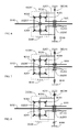
FIG. 1 is a schematic view showing the main structure of the three-end shaft type differential gear set with controllable rotating direction and brake being structured by a planetary gear set, according to one embodiment of the present invention. -
FIG. 2 is a schematic view showing the operation state of the rotation shaft (S101) and the rotation shaft (S102) shown inFIG. 1 performing transmission in the same rotating direction, according to one embodiment of the present invention. -
FIG. 3 is a schematic view showing the operation state of the rotation shaft (S101) and the rotation shaft (S102) shown inFIG. 1 performing transmission in different rotating directions, according to one embodiment of the present invention. -
FIG. 4 is a schematic view showing the operation state of the rotation shaft (S101) and the rotation shaft (S102) shown inFIG. 1 being released with no mutual transmission, according to one embodiment of the present invention. -
FIG. 5 is a schematic view showing the operation state of the rotation shaft (S101) and the rotation shaft (S102) shown inFIG. 1 being locked, according to one embodiment of the present invention. -
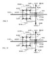
FIG. 6 is a schematic view showing the main structure of the three-end shaft type differential gear set with controllable rotating direction and brake being structured by an epicycle gear set, according to one embodiment of the present invention. -
FIG. 7 is a schematic view showing the operation state of the rotation shaft (S101) and the rotation shaft (S102) shown inFIG. 6 performing transmission in the same rotating direction, according to one embodiment of the present invention. -
FIG. 8 is a schematic view showing the operation state of the rotation shaft (S101) and the rotation shaft (S102) shown inFIG. 6 performing transmission in different rotating directions, according to one embodiment of the present invention. -
FIG. 9 is a schematic view showing the operation state of the rotation shaft (S101) and the rotation shaft (S102) shown inFIG. 6 being released with no mutual transmission, according to one embodiment of the present invention. -
FIG. 10 is a schematic view showing the operation state of the rotation shaft (S101) and the rotation shaft (S102) shown inFIG. 6 being locked, according to one embodiment of the present invention. -
- (A103) , (A103') : Rocker arm of planetary gear
- (AS103) , (AS103') : Sleeve type rotation shaft of planetary gear
- (BK101) : Controllable brake device
- (GL101) : Controllable clutch device
- (DG101 Planetary gear set
- (H100) : Housing
- (S101) , (S102) : Rotation shaft
- (W101) : Sun wheel
- (W102) : Outer annular wheel
- (W103) : Planetary wheel
- (A203) , (A203') : Rocker arm of epicycle wheel
- (AS203) , (AS203') : Sleeve type rotation shaft of epicycle wheel
- (EG201) : Epicycle gear set
- (W201) : Input wheel
- (W202) : Output wheel
- (W203) : Epicycle wheel
- A conventional speed variable gear system, having the same rotating direction or different rotating direction between the input side and the output side, is often installed with a normal/reverse gear set, and through changing the rotating direction of the gear set, the output in normal rotation or reverse rotation is generated; however, the structure thereof is complicated.
- The present invention relates to a three-end shaft type differential gear set with controllable rotating direction and brake, wherein the input side of the three-end shaft type differential gear set performing driving in the same input rotating direction, and through controlling a controllable brake device (BK101) and a controllable clutch device (CL101), the output rotating direction at the output side can be in the same rotating direction or in the reverse rotating direction, or in a released state without mutual transmission, or the input side and the output side are both locked in a non-rotary state.
- The present invention provides a three-end shaft type differential gear set with controllable rotating direction and brake, wherein a three-end shaft type differential gear set is combined with a controllable brake device (BK101) and a controllable clutch device (CL101), and when driving the rotation shaft (S101) in the same rotating direction at the input side, through controlling the controllable brake device (BK101) and the controllable clutch device (CL101), the output side is enabled to perform normal or reverse rotation output, or is in a released state without mutual transmission, or the input side and the output side are both locked in a non-rotary state.
- According to the three-end shaft type differential gear set with controllable rotating direction and brake, the three-end shaft type differential gear set has three output/input ends for inputting rotation, and the differential transmission coupling is mutually formed between the three, and the conventional structure thereof includes a planetary gear set or an epicycle gear set;
- According to the present invention, the three-end shaft type differential gear set with controllable rotating direction and brake structured through a planetary gear set is disclosed as followings:
-
FIG. 1 is a schematic view showing the main structure of the three-end shaft type differential gear set with controllable rotating direction and brake being structured by a planetary gear set, according to one embodiment of the present invention. - Referring to
FIG. 1 , a sun wheel (W101) of the planetary gear set (DG101) is combined with a rotation shaft (S101) for serving as an output/input end, and an outer annular wheel (W102) is combined with a rotation shaft (S102), and a rocker arm of planetary wheel (A 103') linked by the planetary wheel (W103) of the planetary gear set (DG101) is rotated and sleeved on the rotation shaft (S102) through a sleeve type rotation shaft of planetary wheel (AS103'), and a rocker arm of planetary wheel (A103) at the other end is rotated and sleeved on the rotation shaft (S101) through a sleeve type rotation shaft of planetary wheel (AS103), and the rocker arm of planetary wheel (A103) or the sleeve type rotation shaft of planetary wheel (AS103) is connected to an action side of a controllable brake device (BK101), and the other action side of the controllable brake device (BK101) is fixed in a housing (H100), and the planetary gear set (DG101) is also fixed in the housing (H100), which mainly consists of: - -- Planetary gear set (DG101): constituted by a sun wheel (W101) and an outer annular wheel (W102) and at least a planetary wheel (W103), including through gears engaging with each other or through friction wheels mutually performing friction transmissions to form the planetary gear set function, and also constituted including the rotation shaft (S101), the rotation shaft (S102), the rocker arm of planetary wheel (A103), the rocker arm of planetary wheel (AS103'), the sleeve type rotation shaft of planetary wheel (AS103), and the sleeve type rotation shaft of planetary wheel (AS103') and a bearing, for being installed in a shell of the planetary gear set (DG101), and the planetary gear set (DG101) is fixed in the housing (H100);
- --Rocker arm of planetary wheel (A103): having one end provided for allowing the planetary wheel (W103) to rotate and link, and the other end being sleeved on the rotation shaft (S101) through the sleeve type rotation shaft of planetary wheel (AS103), and the rocker arm of planetary wheel (A103) or the sleeve type rotation shaft of planetary wheel (AS103) is connected to an action side of the controllable brake device (BK101), and the other action side of the controllable brake device (BK101) is fixed in the housing (H100);
- --Rocker arm of planetary wheel (AS103'): having one end provided for allowing the planetary wheel (W103) to rotate and link, and the other end being rotated and sleeved on the rotation shaft (S102) through the sleeve type rotation shaft of planetary wheel (AS103');
- --Controllable brake device (BK101): constituted by a brake device controlled by a manual force or mechanical force or hydraulic force or pneumatic force or electromagnetic force, and having action sides for the operations of a brake locking state for engagement or a releasing state for separation, wherein one of the action sides is connected to the sleeve type rotation shaft of planetary wheel (AS103) or the rocker arm of planetary wheel (A103), and the other action side is fixed in the housing (H100);
- --Controllable clutch device (CL101): constituted by a controllable clutch device or a centrifugal clutch device driven by a manual force or mechanical force or hydraulic force or pneumatic force or electromagnetic force, and installed between the rotation shaft (S101) and the rotation shaft (S102) for performing operations of engagement or disengagement;
- --The sun wheel (W101) of the planetary gear set (DG101) is combined with the rotation shaft (S101) for serving as an output/input end, the rocker arm of planetary wheel (A103) and the sleeve type rotation shaft of planetary wheel (AS103) linked by the planetary wheel (W103) of the planetary gear set (DG101) are rotated and sleeved on the rotation shaft (S101), and the mentioned rocker arm of planetary wheel (A103) and the sleeve type rotation shaft of planetary wheel (AS103) is connected to an action side of the controllable brake device (BK101), and the other action side of the controllable brake device (BK101) is fixed in the housing (H100);
- The outer annular wheel (W102) is combined with the rotation shaft (S102) and coupled with the planetary wheel (W103) for transmission, and the rocker arm of planetary wheel (A103') linked by the other end of the planetary wheel (W103) of the planetary gear set (DG101) is provided for driving the sleeve type rotation shaft of planetary wheel (AS103'), and the rocker arm of planetary wheel (AS103') is rotated and sleeved on the rotation shaft (S102);
- The sun wheel (W101) is connected to the rotation shaft (S101) and coupled with the planetary wheel (W103) for transmission;
- The operations of the three-end shaft type differential gear set with controllable rotating direction and brake as shown in
FIG. 1 includes one or more than one of following functions: -
FIG. 2 is a schematic view showing the operation state of the rotation shaft (S101) and the rotation shaft (S102) shown inFIG. 1 performing transmission in the same rotating direction, according to one embodiment of the present invention. - As shown in
FIG. 2 , the operation state is as following: - --When the controllable brake device (BK101) is in the releasing state and the controllable clutch device (CL101) is in the engaging state, the rotation shaft (S101) and the rotation shaft (S102) are in the engaging state for performing the transmission in the same rotating direction;
- As shown in
FIG. 3 , the operation state is as following: - --When the controllable brake device (BK101) is in the brake locking state and the controllable clutch device (CL101) is in the releasing state, the transmission relation of the rotation shaft (S101) and the rotation shaft (S102) is the transmission function in the reverse rotating directions;
- As shown in
FIG. 4 , the operation state is as following: - --When the controllable brake device (BK101) is in the releasing state and the controllable clutch device (CL101) is in the releasing state, the rotation shaft (S101) and the rotation shaft (S102) are released with no mutual transmission.
- As shown in
FIG. 5 , the operation state is as following: - --When the controllable brake device (BK101) is in the brake locking state and the controllable clutch device (CL101) is in the engaging state, the rotation shaft (S101) and the rotation shaft (S102) are locked.
- According to the three-end shaft type differential gear set with controllable rotating direction and brake of the present invention, the three-end shaft type differential gear set has three output/input ends for inputting rotation, and the differential transmission coupling is mutually formed between the three, and the conventional structure thereof includes a planetary gear set or an epicycle gear set;
- According to the present invention, the three-end shaft type differential gear set with controllable rotating direction and brake structured through an epicycle gear set is disclosed as followings:
-
FIG. 6 is a schematic view showing the main structure of the three-end shaft type differential gear set with controllable rotating direction and brake being structured by an epicycle gear set, according to one embodiment of the present invention. - Referring to
FIG. 6 , an input wheel (W201) of the epicycle gear set (EG201) is connected to the rotation shaft (S101) for being served as an output/input end, and an output wheel (W202) is combined with the rotation shaft (S102), a rocker arm of epicycle wheel (A203') linked by an epicycle wheel (W203) of the epicycle gear set (EG201) is rotated and sleeved on the rotation shaft (S102) through a sleeve type rotation shaft of epicycle wheel (AS203'), and an rocker arm of epicycle wheel (A203) at the other end is rotated and sleeved on the rotation shaft (S101) through a sleeve type rotation shaft of epicycle wheel (AS203), and the rocker arm of epicycle wheel (A203) or the sleeve type rotation shaft of epicycle wheel (AS203) is connected to an action side of the controllable brake device (BK101), and the other action side of the controllable brake device (BK101) is fixed in the housing (H100), and the epicycle gear set (EG201) is also fixed in the housing (H100); which mainly consists of: - --Epicycle gear set (EG201): constituted by an input wheel (W201) and an output wheel (W202) and at least an epicycle wheel (W203), and including through bevel gears engaging with each other or through bevel friction wheels mutually performing friction transmissions to form the epicycle gear set function, and also constituted including the rotation shaft (S101), the rotation shaft (S102), the rocker arm of epicycle wheel (A203), the rocker arm of epicycle wheel (A203'), the sleeve type rotation shaft of epicycle wheel (AS203), the sleeve type rotation shaft of epicycle wheel (AS203') and a bearing, for being installed in a shell of the epicycle gear set (EG201), and the epicycle gear set (EG201) is fixed in the housing (H100); the speed ratio of the mentioned rotation shaft (S101) and the rotation shaft (S102) can be the same or different;
- --Rocker arm of epicycle wheel (A203): having one end provided for allowing the epicycle wheel (W203) to rotate and link, and the other end being sleeved on the rotation shaft (S101) through the sleeve type rotation shaft of epicycle wheel (AS203), the rocker arm of epicycle wheel (A203) or the sleeve type rotation shaft of epicycle wheel (AS203) is connected to an action side of the controllable brake device (BK101), and the other action side of the controllable brake device (BK101) is fixed in the housing (H100);
- --Rocker arm of epicycle wheel (A203'): having one end provided for allowing the epicycle wheel (W203) to rotate and link, and the other end being rotated and sleeved on the rotation shaft (S102) through the sleeve type rotation shaft of epicycle wheel (AS203');
- --Controllable brake device (BK101): constituted by a brake device controlled by a manual force or mechanical force or hydraulic force or pneumatic force or electromagnetic force, and having action sides for the operations of a brake locking state for engagement or a releasing state for separation, wherein one of the action sides is connected to the sleeve type rotation shaft of epicycle wheel (AS203) or the rocker arm of epicycle wheel (A203), and the other action side is fixed in the housing (H100);
- --Controllable clutch device (CL101): constituted by a controllable clutch device or a centrifugal clutch device driven by a manual force or mechanical force or hydraulic force or pneumatic force or electromagnetic force, and installed between the rotation shaft (S101) and the rotation shaft (S102) for performing operations of engagement or disengagement;
- --The input wheel (W201) of the epicycle gear set (EG201) is connected to the rotation shaft (S101) for serving as an output/input end, the rocker arm of epicycle wheel (A203) and the sleeve type rotation shaft of epicycle wheel (AS203) linked by the epicycle wheel (W203) of the epicycle gear set (EG201) are rotated and sleeved on the rotation shaft (S101), and the mentioned rocker arm of epicycle wheel (A203) or the sleeve type rotation shaft of epicycle wheel (AS203) is connected to an action side of the controllable brake device (BK101), and the other action side of the controllable brake device (BK101) is fixed in the housing (H100);
- The output wheel (W202) is connected to the rotation shaft (S102) and coupled with the epicycle wheel (W203) for transmission, and the rocker arm of epicycle wheel (A203') linked at the other end of the epicycle wheel (W203) of the epicycle gear set (EG201) is provided for driving the sleeve type rotation shaft of epicycle wheel (AS203'), and the rocker arm of epicycle wheel (A203') is rotated and sleeved on the rotation shaft (S102);
- The input wheel (W201) is connected to the rotation shaft (S101) and coupled with the epicycle wheel (W203) for transmission;
- The operations of the three-end shaft type differential gear set with controllable rotating direction and brake as shown in
FIG. 6 include one or more than one of following functions: -
FIG. 7 is a schematic view showing the operation state of the rotation shaft (S101) and the rotation shaft (S102) shown inFIG. 6 performing transmission in the same rotating direction, according to one embodiment of the present invention. - As shown in
FIG. 7 , the operation state is as following: - --When the controllable brake device (BK101) is in the releasing state and the controllable clutch device (CL101) is in the engaging state, the rotation shaft (S101) and the rotation shaft (S102) are in the engaging state for performing the transmission in the same rotating direction;
- As shown in
FIG. 8 , the operation state is as following: - --When the controllable brake device (BK101) is in the brake locking state and the controllable clutch device (CL101) is in the releasing state, the transmission relation of the rotation shaft (S101) and the rotation shaft (S102) is the transmission function in the reverse rotating directions;
- As shown in
FIG. 9 , the operation state is as following: - --When the controllable brake device (BK101) is in the releasing state and the controllable clutch device (CL101) is in the releasing state, the rotation shaft (S101) and the rotation shaft (S102) are released with no mutual transmission.
- As shown in
FIG. 10 , the operation state is as following: - --When the controllable brake device (BK101) is in the brake locking state and the controllable clutch device (CL101) is in the engaging state, the rotation shaft (S101) and the rotation shaft (S102) are in the locked state.
Claims (11)
- A three-end shaft type differential gear set with controllable rotating direction and brake, wherein the input side of the three-end shaft type differential gear set performing driving in the same input rotating direction, and through controlling a controllable brake device (BK101) and a controllable clutch device (CL101), the output rotating direction at the output side can be in the same rotating direction or in the reverse rotating direction, or in a released state without mutual transmission, or the input side and the output side are both locked in a non-rotary state.
- A three-end shaft type differential gear set with controllable rotating direction and brake as claimed in claim 1, wherein a sun wheel (W101) of the planetary gear set (DG101) is combined with a rotation shaft (S101) for serving as an output/input end, and an outer annular wheel (W102) is combined with a rotation shaft (S102), and a rocker arm of planetary wheel (A103') linked by the planetary wheel (W103) of the planetary gear set (DG101) is rotated and sleeved on the rotation shaft (S102) through a sleeve type rotation shaft of planetary wheel (AS103'), and a rocker arm of planetary wheel (A103) at the other end is rotated and sleeved on the rotation shaft (S101) through a sleeve type rotation shaft of planetary wheel (AS103), and the rocker arm of planetary wheel (A103) or the sleeve type rotation shaft of planetary wheel (AS103) is connected to an action side of a controllable brake device (BK101), and the other action side of the controllable brake device (BK101) is fixed in a housing (H100), and the planetary gear set (DG101) is also fixed in the housing (H100), which mainly consists of:-- Planetary gear set (DG101): constituted by a sun wheel (W101) and an outer annular wheel (W102) and at least a planetary wheel (W103), including through gears engaging with each other or through friction wheels mutually performing friction transmissions to form the planetary gear set function, and also constituted including the rotation shaft (S101), the rotation shaft (S102), the rocker arm of planetary wheel (A103), the rocker arm of planetary wheel (AS103'), the sleeve type rotation shaft of planetary wheel (AS103), and the sleeve type rotation shaft of planetary wheel (AS103') and a bearing, for being installed in a shell of the planetary gear set (DG101), and the planetary gear set (DG101) is fixed in the housing (H100);--Rocker arm of planetary wheel (A103): having one end provided for allowing the planetary wheel (W103) to rotate and link, and the other end being sleeved on the rotation shaft (S101) through the sleeve type rotation shaft of planetary wheel (AS103), and the rocker arm of planetary wheel (A103) or the sleeve type rotation shaft of planetary wheel (AS103) is connected to an action side of the controllable brake device (BK101), and the other action side of the controllable brake device (BK101) is fixed in the housing (H100);--Rocker arm of planetary wheel (AS103'): having one end provided for allowing the planetary wheel (W103) to rotate and link, and the other end being rotated and sleeved on the rotation shaft (S102) through the sleeve type rotation shaft of planetary wheel (AS103');--Controllable brake device (BK101): constituted by a brake device controlled by a manual force or mechanical force or hydraulic force or pneumatic force or electromagnetic force, and having action sides for the operations of a brake locking state for engagement or a releasing state for separation, wherein one of the action sides is connected to the sleeve type rotation shaft of planetary wheel (AS103) or the rocker arm of planetary wheel (A103), and the other action side is fixed in the housing (H100);--Controllable clutch device (CL101): constituted by a controllable clutch device or a centrifugal clutch device driven by a manual force or mechanical force or hydraulic force or pneumatic force or electromagnetic force, and installed between the rotation shaft (S101) and the rotation shaft (S102) for performing operations of engagement or disengagement;--The sun wheel (W101) of the planetary gear set (DG101) is combined with the rotation shaft (S101) for serving as an output/input end, the rocker arm of planetary wheel (A103) and the sleeve type rotation shaft of planetary wheel (AS103) linked by the planetary wheel (W103) of the planetary gear set (DG101) are rotated and sleeved on the rotation shaft (S101), and the mentioned rocker arm of planetary wheel (A103) and the sleeve type rotation shaft of planetary wheel (AS103) is connected to an action side of the controllable brake device (BK101), and the other action side of the controllable brake device (BK101) is fixed in the housing (H100); The outer annular wheel (W102) is combined with the rotation shaft (S102) and coupled with the planetary wheel (W103) for transmission, and the rocker arm of planetary wheel (A103') linked by the other end of the planetary wheel (W103) of the planetary gear set (DG101) is provided for driving the sleeve type rotation shaft of planetary wheel (AS103'), and the rocker arm of planetary wheel (AS103') is rotated and sleeved on the rotation shaft (S102);
The sun wheel (W101) is connected to the rotation shaft (S101) and coupled with the planetary wheel (W103) for transmission. - A three-end shaft type differential gear set with controllable rotating direction and brake as claimed in claim 2, wherein when the controllable brake device (BK101) is in the releasing state and the controllable clutch device (CL101) is in the engaging state, the rotation shaft (S101) and the rotation shaft (S102) are in the engaging state for performing the transmission in the same rotating direction.
- A three-end shaft type differential gear set with controllable rotating direction and brake as claimed in claim 2, wherein when he controllable brake device (BK101) is in the brake locking state and the controllable clutch device (CL101) is in the releasing state, the transmission relation of the rotation shaft (S101) and the rotation shaft (S102) is the transmission function in the reverse rotating directions.
- A three-end shaft type differential gear set with controllable rotating direction and brake as claimed in claim 2, wherein when the controllable brake device (BK101) is in the releasing state and the controllable clutch device (CL101) is in the releasing state, the rotation shaft (S101) and the rotation shaft (S102) are released with no mutual transmission.
- A three-end shaft type differential gear set with controllable rotating direction and brake as claimed in claim 2, wherein when the controllable brake device (BK101) is in the brake locking state and the controllable clutch device (CL101) is in the engaging state, the rotation shaft (S101) and the rotation shaft (S102) are locked.
- A three-end shaft type differential gear set with controllable rotating direction and brake as claimed in claim 1, wherein an input wheel (W201) of the epicycle gear set (EG201) is connected to the rotation shaft (S101) for being served as an output/input end, and an output wheel (W202) is combined with the rotation shaft (S102), a rocker arm of epicycle wheel (A203') linked by an epicycle wheel (W203) of the epicycle gear set (EG201) is rotated and sleeved on the rotation shaft (S102) through a sleeve type rotation shaft of epicycle wheel (AS203'), and an rocker arm of epicycle wheel (A203) at the other end is rotated and sleeved on the rotation shaft (S101) through a sleeve type rotation shaft of epicycle wheel (AS203), and the rocker arm of epicycle wheel (A203) or the sleeve type rotation shaft of epicycle wheel (AS203) is connected to an action side of the controllable brake device (BK101), and the other action side of the controllable brake device (BK101) is fixed in the housing (H100), and the epicycle gear set (EG201) is also fixed in the housing (H100); which mainly consists of:--Epicycle gear set (EG201): constituted by an input wheel (W201) and an output wheel (W202) and at least an epicycle wheel (W203), and including through bevel gears engaging with each other or through bevel friction wheels mutually performing friction transmissions to form the epicycle gear set function, and also constituted including the rotation shaft (S101), the rotation shaft (S102), the rocker arm of epicycle wheel (A203), the rocker arm of epicycle wheel (A203'), the sleeve type rotation shaft of epicycle wheel (AS203), the sleeve type rotation shaft of epicycle wheel (AS203') and a bearing, for being installed in a shell of the epicycle gear set (EG201), and the epicycle gear set (EG201) is fixed in the housing (H100); the speed ratio of the mentioned rotation shaft (S101) and the rotation shaft (S102) can be the same or different;--Rocker arm of epicycle wheel (A203): having one end provided for allowing the epicycle wheel (W203) to rotate and link, and the other end being sleeved on the rotation shaft (S101) through the sleeve type rotation shaft of epicycle wheel (AS203), the rocker arm of epicycle wheel (A203) or the sleeve type rotation shaft of epicycle wheel (AS203) is connected to an action side of the controllable brake device (BK101), and the other action side of the controllable brake device (BK101) is fixed in the housing (H 100);--Rocker arm of epicycle wheel (A203'): having one end provided for allowing the epicycle wheel (W203) to rotate and link, and the other end being rotated and sleeved on the rotation shaft (S102) through the sleeve type rotation shaft of epicycle wheel (AS203');--Controllable brake device (BK101): constituted by a brake device controlled by a manual force or mechanical force or hydraulic force or pneumatic force or electromagnetic force, and having action sides for the operations of a brake locking state for engagement or a releasing state for separation, wherein one of the action sides is connected to the sleeve type rotation shaft of epicycle wheel (AS203) or the rocker arm of epicycle wheel (A203), and the other action side is fixed in the housing (H100);--Controllable clutch device (CL101): constituted by a controllable clutch device or a centrifugal clutch device driven by a manual force or mechanical force or hydraulic force or pneumatic force or electromagnetic force, and installed between the rotation shaft (S101) and the rotation shaft (S102) for performing operations of engagement or disengagement;--The input wheel (W201) of the epicycle gear set (EG201) is connected to the rotation shaft (S101) for serving as an output/input end, the rocker arm of epicycle wheel (A203) and the sleeve type rotation shaft of epicycle wheel (AS203) linked by the epicycle wheel (W203) of the epicycle gear set (EG201) are rotated and sleeved on the rotation shaft (S101), and the mentioned rocker arm of epicycle wheel (A203) or the sleeve type rotation shaft of epicycle wheel (AS203) is connected to an action side of the controllable brake device (BK101), and the other action side of the controllable brake device (BK101) is fixed in the housing (H100);
The output wheel (W202) is connected to the rotation shaft (S102) and coupled with the epicycle wheel (W203) for transmission, and the rocker arm of epicycle wheel (A203') linked at the other end of the epicycle wheel (W203) of the epicycle gear set (EG20 1) is provided for driving the sleeve type rotation shaft of epicycle wheel (AS203'), and the rocker arm of epicycle wheel (A203') is rotated and sleeved on the rotation shaft (S102);
The input wheel (W201) is connected to the rotation shaft (S101) and coupled with the epicycle wheel (W203) for transmission. - A three-end shaft type differential gear set with controllable rotating direction and brake as claimed in claim 7, wherein when the controllable brake device (BK101) is in the releasing state and the controllable clutch device (CL101) is in the engaging state, the rotation shaft (S101) and the rotation shaft (S102) are in the engaging state for performing the transmission in the same rotating direction.
- A three-end shaft type differential gear set with controllable rotating direction and brake as claimed in claim 7, wherein when the controllable brake device (BK101) is in the brake locking state, and the controllable clutch device (CL101) is in the releasing state, the transmission relation of the rotation shaft (S101) and the rotation shaft (S102) is the transmission function in the reverse rotating directions.
- A three-end shaft type differential gear set with controllable rotating direction and brake as claimed in claim 7, wherein when the controllable brake device (BK101) is in the releasing state and the controllable clutch device (CL101) is in the releasing state, the rotation shaft (S101) and the rotation shaft (S102) are released with no mutual transmission.
- A three-end shaft type differential gear set with controllable rotating direction and brake as claimed in claim 7, wherein when the controllable brake device (BK101) is in the brake locking state and the controllable clutch device (CL101) is in the engaging state, the rotation shaft (S101) and the rotation shaft (S102) are in the locked state.
Applications Claiming Priority (1)
| Application Number | Priority Date | Filing Date | Title |
|---|---|---|---|
| US13/086,633 US8475324B2 (en) | 2011-04-14 | 2011-04-14 | Three-end shaft type differential gear set with controllable rotating direction and brake |
Publications (2)
| Publication Number | Publication Date |
|---|---|
| EP2511571A2 true EP2511571A2 (en) | 2012-10-17 |
| EP2511571A3 EP2511571A3 (en) | 2017-08-02 |
Family
ID=45977232
Family Applications (1)
| Application Number | Title | Priority Date | Filing Date |
|---|---|---|---|
| EP12163389.5A Withdrawn EP2511571A3 (en) | 2011-04-14 | 2012-04-05 | Three-end shaft type differential gear set with controllable rotating direction and brake |
Country Status (6)
| Country | Link |
|---|---|
| US (1) | US8475324B2 (en) |
| EP (1) | EP2511571A3 (en) |
| JP (1) | JP6101430B2 (en) |
| KR (1) | KR101898428B1 (en) |
| CN (2) | CN102734425B (en) |
| TW (2) | TWI614433B (en) |
Cited By (1)
| Publication number | Priority date | Publication date | Assignee | Title |
|---|---|---|---|---|
| CN108814824A (en) * | 2017-05-10 | 2018-11-16 | 国家康复辅具研究中心 | A kind of wheelchair |
Families Citing this family (7)
| Publication number | Priority date | Publication date | Assignee | Title |
|---|---|---|---|---|
| US8475313B2 (en) * | 2011-02-16 | 2013-07-02 | Tai-Her Yang | Bicycle with output in constant rotating direction and having internal rocker arm epicycle wheel set |
| US20120231911A1 (en) * | 2011-03-11 | 2012-09-13 | Tai-Her Yang | Power train having manipulatable epicyclic type clutch device |
| US8475324B2 (en) * | 2011-04-14 | 2013-07-02 | Tai-Her Yang | Three-end shaft type differential gear set with controllable rotating direction and brake |
| DE102011114046A1 (en) * | 2011-09-22 | 2013-03-28 | Knorr-Bremse Systeme für Nutzfahrzeuge GmbH | Compressor system and method of operating a compressor system |
| CN103363050A (en) * | 2012-12-28 | 2013-10-23 | 韩志群 | Damping clutch transmission |
| JP6492461B2 (en) * | 2014-08-29 | 2019-04-03 | ブラザー工業株式会社 | Image forming apparatus |
| CN108343722B (en) * | 2018-04-24 | 2019-12-03 | 六安永贞匠道机电科技有限公司 | A kind of power of automobile continues output type clutch |
Family Cites Families (20)
| Publication number | Priority date | Publication date | Assignee | Title |
|---|---|---|---|---|
| DE2731814A1 (en) * | 1976-07-24 | 1978-01-26 | Automotive Prod Co Ltd | POWER TRANSMISSION DEVICE |
| FR2522100B1 (en) * | 1982-02-22 | 1987-04-24 | Valeo | TRANSMISSION BETWEEN A POWER TAKE-OFF AND A RECEIVING SHAFT, IN PARTICULAR FOR A MOTOR VEHICLE |
| JP2596931B2 (en) * | 1987-04-27 | 1997-04-02 | マツダ株式会社 | Power transmission device for four-wheel drive vehicle |
| ATA6192A (en) * | 1992-01-16 | 1997-05-15 | Avl Verbrennungskraft Messtech | DRIVE DEVICE DRIVE DEVICE |
| CN1044275C (en) * | 1994-03-24 | 1999-07-21 | 杨泰和 | Differential gear train with speed ratio controlled by input direction |
| DE4423651A1 (en) * | 1994-07-06 | 1996-01-11 | Zahnradfabrik Friedrichshafen | Drive device for a motor vehicle, in particular a construction machine |
| CN2280172Y (en) * | 1996-10-22 | 1998-04-29 | 牟广琴 | Planet gear type reversal device |
| JP3807690B2 (en) * | 1997-05-13 | 2006-08-09 | 株式会社ハーモニック・ドライブ・システムズ | Rotation transmission mechanism using planetary gear mechanism |
| JP3866395B2 (en) * | 1997-10-30 | 2007-01-10 | 本田技研工業株式会社 | Planetary gear mechanism |
| US20030089569A1 (en) * | 2000-11-17 | 2003-05-15 | Roumen Antonov | Trasmission devices, for ground vehicles and more particularly for molor-cars |
| JP4096579B2 (en) * | 2002-02-27 | 2008-06-04 | アイシン精機株式会社 | Planetary gear mechanism |
| JP4048950B2 (en) * | 2002-12-27 | 2008-02-20 | アイシン・エィ・ダブリュ株式会社 | Planetary gear for automatic transmission |
| JP5204098B2 (en) * | 2006-04-30 | 2013-06-05 | トマクテック・アクティーゼルスカブ | transmission |
| CN102076992B (en) * | 2008-04-30 | 2014-09-24 | 迪姆肯公司 | Planetary gear system with flexpins |
| DE102008027672B4 (en) * | 2008-06-05 | 2012-03-29 | Getrag Driveline Systems Gmbh | Powertrain for a four-wheel drive vehicle and method for driving the same |
| CN101363518A (en) * | 2008-09-16 | 2009-02-11 | 徐晋 | Zero-cross gear changes and method thereof |
| JP2010216613A (en) * | 2009-03-18 | 2010-09-30 | Toyota Motor Corp | Driving device for vehicle |
| US8376886B2 (en) * | 2010-02-03 | 2013-02-19 | Tai-Her Yang | Coaxial epicyclic gear train with bidirectional input and one-way output |
| US8257220B2 (en) * | 2010-02-03 | 2012-09-04 | Tai-Her Yang | Clutch type reversible transmission bicycle with bidirectional input and one-way output |
| US8475324B2 (en) * | 2011-04-14 | 2013-07-02 | Tai-Her Yang | Three-end shaft type differential gear set with controllable rotating direction and brake |
-
2011
- 2011-04-14 US US13/086,633 patent/US8475324B2/en not_active Expired - Fee Related
-
2012
- 2012-04-05 EP EP12163389.5A patent/EP2511571A3/en not_active Withdrawn
- 2012-04-06 CN CN201210099146.7A patent/CN102734425B/en not_active Expired - Fee Related
- 2012-04-06 CN CN2012201421697U patent/CN202597634U/en not_active Expired - Lifetime
- 2012-04-06 TW TW101112154A patent/TWI614433B/en not_active IP Right Cessation
- 2012-04-06 TW TW101206198U patent/TWM451452U/en not_active IP Right Cessation
- 2012-04-12 JP JP2012091028A patent/JP6101430B2/en not_active Expired - Fee Related
- 2012-04-13 KR KR1020120038285A patent/KR101898428B1/en active Active
Non-Patent Citations (1)
| Title |
|---|
| None |
Cited By (1)
| Publication number | Priority date | Publication date | Assignee | Title |
|---|---|---|---|---|
| CN108814824A (en) * | 2017-05-10 | 2018-11-16 | 国家康复辅具研究中心 | A kind of wheelchair |
Also Published As
| Publication number | Publication date |
|---|---|
| JP6101430B2 (en) | 2017-03-22 |
| TWI614433B (en) | 2018-02-11 |
| TWM451452U (en) | 2013-04-21 |
| CN102734425A (en) | 2012-10-17 |
| KR101898428B1 (en) | 2018-10-29 |
| JP2012225507A (en) | 2012-11-15 |
| KR20120117670A (en) | 2012-10-24 |
| US20120264558A1 (en) | 2012-10-18 |
| CN202597634U (en) | 2012-12-12 |
| CN102734425B (en) | 2016-08-17 |
| EP2511571A3 (en) | 2017-08-02 |
| US8475324B2 (en) | 2013-07-02 |
| TW201248041A (en) | 2012-12-01 |
Similar Documents
| Publication | Publication Date | Title |
|---|---|---|
| CN103221242B (en) | hybrid drive | |
| EP2740968B1 (en) | Bi-rotating directional input and constant rotating directional output wheel system | |
| US8282524B2 (en) | Transmission device for distributing a drive torque to at least two output shafts | |
| US20110190085A1 (en) | Clutch control reversible transmission wheel system with bidirectional input and one-way output | |
| US8475324B2 (en) | Three-end shaft type differential gear set with controllable rotating direction and brake | |
| US8413547B2 (en) | Retrograde torque limit gear train with bidirectional input and one-way output | |
| KR102017774B1 (en) | Power transmission | |
| CN103807387A (en) | Triple clutch multi-speed transmission | |
| AU2011200438A1 (en) | Coaxial epicyclic gear train with bidirectional input and one-way output | |
| US10598259B2 (en) | Transmission for a motor vehicle | |
| US20130036848A1 (en) | Vehicle Transmissions | |
| US20190162274A1 (en) | Gear Mechanism for a Motor Vehicle | |
| US8439783B2 (en) | Penetrating shaft type planetary gear train with bidirectional input and one-way output | |
| CA2768918C (en) | Clutch device structured with controllable epicycle gear set and applied power train thereof | |
| KR101467058B1 (en) | Transmission apparatus preventing a torque drop during shifting | |
| US9897178B2 (en) | Manipulatable epicyclic type clutch device coupled with hybrid power train | |
| US8568265B2 (en) | Clutch function device structured with controllable epicycle gear set | |
| US20120231911A1 (en) | Power train having manipulatable epicyclic type clutch device | |
| CN105008767A (en) | Multi-stage planetary transmission | |
| KR101272716B1 (en) | Speed reduction apparatus for vehicles | |
| JP2008075721A (en) | Automatic transmission | |
| CN105074275A (en) | Multi-stage planetary transmission | |
| KR101674272B1 (en) | Transmission for vehicle | |
| KR20200001779A (en) | Transmission for electric vehicle | |
| JP3167161U (en) | Continuously variable transmission |
Legal Events
| Date | Code | Title | Description |
|---|---|---|---|
| PUAI | Public reference made under article 153(3) epc to a published international application that has entered the european phase |
Free format text: ORIGINAL CODE: 0009012 |
|
| AK | Designated contracting states |
Kind code of ref document: A2 Designated state(s): AL AT BE BG CH CY CZ DE DK EE ES FI FR GB GR HR HU IE IS IT LI LT LU LV MC MK MT NL NO PL PT RO RS SE SI SK SM TR |
|
| AX | Request for extension of the european patent |
Extension state: BA ME |
|
| PUAL | Search report despatched |
Free format text: ORIGINAL CODE: 0009013 |
|
| AK | Designated contracting states |
Kind code of ref document: A3 Designated state(s): AL AT BE BG CH CY CZ DE DK EE ES FI FR GB GR HR HU IE IS IT LI LT LU LV MC MK MT NL NO PL PT RO RS SE SI SK SM TR |
|
| AX | Request for extension of the european patent |
Extension state: BA ME |
|
| RIC1 | Information provided on ipc code assigned before grant |
Ipc: F16H 3/60 20060101AFI20170626BHEP |
|
| STAA | Information on the status of an ep patent application or granted ep patent |
Free format text: STATUS: THE APPLICATION HAS BEEN PUBLISHED |
|
| STAA | Information on the status of an ep patent application or granted ep patent |
Free format text: STATUS: THE APPLICATION IS DEEMED TO BE WITHDRAWN |
|
| 18D | Application deemed to be withdrawn |
Effective date: 20180203 |