EP2511496A2 - Stoichiometric exhaust gas recirculation combustor - Google Patents
Stoichiometric exhaust gas recirculation combustor Download PDFInfo
- Publication number
- EP2511496A2 EP2511496A2 EP12164063A EP12164063A EP2511496A2 EP 2511496 A2 EP2511496 A2 EP 2511496A2 EP 12164063 A EP12164063 A EP 12164063A EP 12164063 A EP12164063 A EP 12164063A EP 2511496 A2 EP2511496 A2 EP 2511496A2
- Authority
- EP
- European Patent Office
- Prior art keywords
- exhaust gas
- flow
- gas recovery
- stoichiometric exhaust
- combustor
- Prior art date
- Legal status (The legal status is an assumption and is not a legal conclusion. Google has not performed a legal analysis and makes no representation as to the accuracy of the status listed.)
- Granted
Links
Images
Classifications
-
- F—MECHANICAL ENGINEERING; LIGHTING; HEATING; WEAPONS; BLASTING
- F02—COMBUSTION ENGINES; HOT-GAS OR COMBUSTION-PRODUCT ENGINE PLANTS
- F02C—GAS-TURBINE PLANTS; AIR INTAKES FOR JET-PROPULSION PLANTS; CONTROLLING FUEL SUPPLY IN AIR-BREATHING JET-PROPULSION PLANTS
- F02C3/00—Gas-turbine plants characterised by the use of combustion products as the working fluid
- F02C3/34—Gas-turbine plants characterised by the use of combustion products as the working fluid with recycling of part of the working fluid, i.e. semi-closed cycles with combustion products in the closed part of the cycle
-
- F—MECHANICAL ENGINEERING; LIGHTING; HEATING; WEAPONS; BLASTING
- F23—COMBUSTION APPARATUS; COMBUSTION PROCESSES
- F23C—METHODS OR APPARATUS FOR COMBUSTION USING FLUID FUEL OR SOLID FUEL SUSPENDED IN A CARRIER GAS OR AIR
- F23C9/00—Combustion apparatus characterised by arrangements for returning combustion products or flue gases to the combustion chamber
- F23C9/08—Combustion apparatus characterised by arrangements for returning combustion products or flue gases to the combustion chamber for reducing temperature in combustion chamber, e.g. for protecting walls of combustion chamber
-
- F—MECHANICAL ENGINEERING; LIGHTING; HEATING; WEAPONS; BLASTING
- F23—COMBUSTION APPARATUS; COMBUSTION PROCESSES
- F23R—GENERATING COMBUSTION PRODUCTS OF HIGH PRESSURE OR HIGH VELOCITY, e.g. GAS-TURBINE COMBUSTION CHAMBERS
- F23R3/00—Continuous combustion chambers using liquid or gaseous fuel
- F23R3/02—Continuous combustion chambers using liquid or gaseous fuel characterised by the air-flow or gas-flow configuration
- F23R3/04—Air inlet arrangements
-
- F—MECHANICAL ENGINEERING; LIGHTING; HEATING; WEAPONS; BLASTING
- F23—COMBUSTION APPARATUS; COMBUSTION PROCESSES
- F23R—GENERATING COMBUSTION PRODUCTS OF HIGH PRESSURE OR HIGH VELOCITY, e.g. GAS-TURBINE COMBUSTION CHAMBERS
- F23R3/00—Continuous combustion chambers using liquid or gaseous fuel
- F23R3/42—Continuous combustion chambers using liquid or gaseous fuel characterised by the arrangement or form of the flame tubes or combustion chambers
-
- F—MECHANICAL ENGINEERING; LIGHTING; HEATING; WEAPONS; BLASTING
- F05—INDEXING SCHEMES RELATING TO ENGINES OR PUMPS IN VARIOUS SUBCLASSES OF CLASSES F01-F04
- F05D—INDEXING SCHEME FOR ASPECTS RELATING TO NON-POSITIVE-DISPLACEMENT MACHINES OR ENGINES, GAS-TURBINES OR JET-PROPULSION PLANTS
- F05D2270/00—Control
- F05D2270/01—Purpose of the control system
- F05D2270/08—Purpose of the control system to produce clean exhaust gases
- F05D2270/082—Purpose of the control system to produce clean exhaust gases with as little NOx as possible
-
- F—MECHANICAL ENGINEERING; LIGHTING; HEATING; WEAPONS; BLASTING
- F23—COMBUSTION APPARATUS; COMBUSTION PROCESSES
- F23C—METHODS OR APPARATUS FOR COMBUSTION USING FLUID FUEL OR SOLID FUEL SUSPENDED IN A CARRIER GAS OR AIR
- F23C2900/00—Special features of, or arrangements for combustion apparatus using fluid fuels or solid fuels suspended in air; Combustion processes therefor
- F23C2900/09001—Cooling flue gas before returning them to flame or combustion chamber
Definitions
- the present application relates generally to gas turbine engines and more particularly relates to a stoichiometric exhaust gas recirculation turbine system with a combustor having an extended flow sleeve so as to provide adequate cooling and extraction.
- EGR exhaust gas recirculation
- SEGR stoichiometric exhaust gas recirculation
- the present application provides a stoichiometric exhaust gas recovery turbine system.
- the stoichiometric exhaust gas recovery turbine system may include a main compressor for compressing a flow of ambient air, a turbine, and a stoichiometric exhaust gas recovery combustor.
- the stoichiometric exhaust gas recovery combustor may include a combustion liner, an extended flow sleeve in communication with the main compressor, and an extraction port in communication with the turbine.
- the extended flow sleeve receives the flow of ambient air from the main compressor so as to cool the combustion liner and then the flow of ambient air splits into an extraction flow to the turbine via the extraction port and a combustion flow within the combustion liner.
- the present application further provides a method of operating a stoichiometric exhaust gas recovery turbine system.
- the method may include the steps of providing an extended flow sleeve about a firing zone of a combustor, flowing ambient air along the extended flow sleeve about the firing zone so as to cool the firing zone, extracting a portion of the ambient airflow downstream of the firing zone, and flowing the remaining portion of the ambient airflow within the firing zone for combustion therein.
- the present application further provides a stoichiometric exhaust gas recovery combustor for combusting a flow of ambient air and a flow of fuel.
- the stoichiometric exhaust gas recovery combustor may include a mixing zone, a firing zone, an extend flow sleeve surrounding the mixing zone and the firing zone, and an extraction port positioned about the flow sleeve and downstream of the firing zone. The flow of ambient air flows through the extended flow sleeve to cool the firing zone and then splits into an extraction flow via the extraction port and a combustion flow into the mixing area.
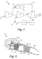
- Fig. 1 shows an example of a stoichiometric exhaust gas recovery turbine system 10.
- the stoichiometric exhaust gas recovery turbine system 10 may include a main compressor 15.
- the main compressor 15 compresses an incoming flow of ambient air 20.
- the main compressor 15 delivers the compressed flow of ambient air 20 to a combustor 25.
- the combustor 25 mixes the compressed flow of ambient air with a compressed flow of fuel 30 and ignites the mixture to create a flow of combustion gases 35.
- the stoichiometric exhaust gas recovery turbine system 10 may include any number of combustors 25.
- the flow of combustion gases 35 is in turn delivered to a turbine 40.
- the flow of combustion gases 35 drives the turbine 40 so as to produce mechanical work.
- the mechanical work produced in the turbine 40 drives the main compressor 15 via a shaft 45 and an external load such as an electrical generator and the like.
- an external load such as an electrical generator and the like.
- Other components and other configurations may be used herein.
- the stoichiometric exhaust gas recovery turbine system 10 also may include a stoichiometric exhaust gas recovery subsystem 55.
- the stoichiometric exhaust gas recovery subsystem 55 may include a stoichiometric exhaust gas recovery compressor 60.
- the stoichiometric exhaust gas recovery compressor 60 may be in communication with and driven by the shaft 45.
- the stoichiometric exhaust gas recovery subsystem 55 also may include a heat recovery steam generator 65 and a cooler 70 downstream of the turbine 40. Other components and other configurations may be used herein.
- the flow of combustion gases 35 through the turbine 40 may contain only low levels of oxygen because of the equilibrium chemistry at the temperatures used for combustion.
- the combustion gases 35 leaving the turbine 40 may be considered a low oxygen recirculation flow 75.
- the low oxygen recirculation flow 75 thus may be cooled in a recirculation loop 80 in the heat recovery steam generator 65 and the cooler 70 with the heat therein available for useful work.
- the now cooled low oxygen recirculation flow 75 then may be compressed within the stoichiometric exhaust gas recovery compressor 60 and mixed with the flow of ambient air 20 and the flow of fuel 30 in the combustor 25 for combustion therein.
- the stoichiometric exhaust gas recovery turbine system 10 and the components described herein are for the purposes of example only.
- the stoichiometric exhaust gas recovery turbine system 10 may have many other components and other configurations.
- a portion of the ambient airflow 20 may be extracted at the combustor 25 and sent to the turbine 40 via a combustion extraction line 85.
- About thirty percent (30%) or more of the ambient airflow 20 may be diverted so as to ensure stoichiometric operation therein.
- the amount of the diversion may depend upon the flow needed to replace the oxidizer such as air or oxygen. Other types and amounts of air extractions may be used herein.
- Fig. 2 shows a stoichiometric exhaust gas recovery combustor 100 as may be described herein.
- the stoichiometric exhaust gas recovery combustor 100 may be used with the stoichiometric exhaust gas recovery turbine system 10 described above and the like.
- the stoichiometric exhaust gas recovery combustor 100 may include one or more fuel nozzles 110 therein.
- the fuel nozzle 110 may be greater in length as compared to typical fuel nozzles for the reasons described below.
- the fuel nozzle 110 may be in communication with a fuel inlet 120.
- the stoichiometric exhaust gas recovery combustor 100 may mix the flow of ambient air 20, the flow of fuel 30, and the low oxygen recirculation flow 75 and then ignite the mixture to produce the flow of combustion gases 35.
- the stoichiometric exhaust gas recovery combustor 100 also may include a combustion liner 130.
- the combustion liner 130 may define a mixing zone 140 and a firing zone 150 therein.
- the fuel nozzle 110 may be positioned within and extends through the mixing zone 140 into the firing zone 150. As with the fuel nozzle 110, the combustion liner 130, the mixing zone 140, and the firing zone 150 may be longer in length as compared to those typically found in a conventional combustor.
- a low oxygen recirculation inlet 160 also may be in communication with the mixing zone 140 for the low oxygen recirculation flow 75.
- An extended flow sleeve 170 may surround the combustion liner 130 and may define an ambient air path 180 therein for the flow of ambient air 20.
- the extended flow sleeve 170 and the recirculated gas may be in communication with the main compressor 15.
- the flow of ambient air 20 in the ambient air path 180 of the extended flow sleeve 170 cools the combustion liner 130 about the firing zone 150 while providing the flow of ambient air 20 to the mixing zone 140.
- the extended flow sleeve 170 also may be longer in length as compared to those of conventional compressors to ensure adequate cooling of the combustion liner 130 about the firing zone 150. Increasing the length of the flow sleeve 170 thus requires the increased length of the other components described above.
- a casing 190 may surround the extended flow sleeve 170 and the combustion liner 130.
- a transition piece 200 may be positioned downstream of the firing zone 150.
- An extraction port 210 may be positioned about the casing 190 and in communication with the ambient air path 180 of the extended flow sleeve 170.
- the extraction port 210 may be in communication with the turbine 40 via the extraction line 85.
- the extraction port 210 may be positioned downstream of the firing zone 150 such that all or most of the ambient airflow 20 passes about the firing zone 150 for cooling therewith.
- the extended flow sleeve 170 may end via one or more flow sleeve apertures 220.
- the one or more flow sleeve apertures 220 may be in communication with the mixing zone 140.
- the extraction port 210 and the one or more flow sleeve apertures 220 thus split the ambient airflow 20 after cooling into an extraction flow 230 that passes through the extraction port 210 to the turbine 40 via the extraction line 85 and a combustion flow 240 that flows into the mixing zone 140 via the one or more flow sleeve apertures 220 for combustion therein.
- Other configurations and other components may be used herein.
- the volume of the extraction flow 230 may be determined by the size, number, and position of the flow sleeve apertures 220 in the extended flow sleeve 170 as compared to the extraction port 210.
- the desired percentage of the ambient airflow 20 thus may be extracted to the turbine 40 via the extraction port 230. Thirty percent (30%) or more of the ambient airflow 20 thus may be extracted.
- the remaining combustion flow 240 then mixes in the mixing zone 140 via the flow sleeve apertures 220 with the low oxygen recirculation flow 75 and ignited with the flow of fuel 30 within the firing zone 150. Because of the extended flow sleeve 170, the desired cooling flow within the ambient air path 180 is maintained about the combustion liner 130 near the firing zone 150.
- the stoichiometric exhaust gas recovery combustor 100 thus meets increased air extraction requirements without diminishing the cooling flow along the combustion liner 130 about the firing zone 150. Likewise, the stoichiometric exhaust gas recovery combustor 100 meets component lifetime requirements despite the increased extraction.
Landscapes
- Engineering & Computer Science (AREA)
- Chemical & Material Sciences (AREA)
- Combustion & Propulsion (AREA)
- Mechanical Engineering (AREA)
- General Engineering & Computer Science (AREA)
- Life Sciences & Earth Sciences (AREA)
- Sustainable Development (AREA)
Abstract
Description
- The present application relates generally to gas turbine engines and more particularly relates to a stoichiometric exhaust gas recirculation turbine system with a combustor having an extended flow sleeve so as to provide adequate cooling and extraction.
- In a gas turbine engine, operational efficiency generally increases as the temperature of the combustion stream increases. Higher combustion stream temperatures, however, may produce higher levels of nitrogen oxides (NOx) and other types of emissions. These emissions may be subject to both federal and state regulation in the United States and also subject to similar regulations abroad. A balancing act thus exists between operating a gas turbine in an efficient temperature range while also ensuring that the output of NOx and other types of regulated emissions remain below mandated levels. Further complicating this balance, non-stoichiometric combustion may produce nitrogen oxides at the high temperatures as described above. Reducing combustion temperatures, however, may result in higher carbon monoxide (CO) emission levels because of the incomplete oxidation of the fuel. Carbon monoxide also is a regulated emission.
- Recently, various types of exhaust gas recirculation (EGR) techniques, and more particularly stoichiometric exhaust gas recirculation (SEGR) techniques, have been useful in reducing overall emissions of nitrous oxides and carbon monoxide. Turbines using stoichiometric exhaust gas recirculation techniques, however, may require a significant increase in the amount of air extracted from the combustor, about thirty percent (30%) or more depending upon the flow needed to replace the oxidizer such as air or oxygen. Such a significant extraction, however, may impact at least on overall combustor cooling and combustion temperatures therein as well as the overall lifetime of the combustor components.
- There is thus a desire for an improved combustor design for the use with a stoichiometric exhaust gas recirculation turbine system. Preferably such a design would permit adequate air extraction to the turbine while maintaining adequate combustor cooling and combustor temperatures for improved efficiency and overall component lifetime.
- The present application provides a stoichiometric exhaust gas recovery turbine system. The stoichiometric exhaust gas recovery turbine system may include a main compressor for compressing a flow of ambient air, a turbine, and a stoichiometric exhaust gas recovery combustor. The stoichiometric exhaust gas recovery combustor may include a combustion liner, an extended flow sleeve in communication with the main compressor, and an extraction port in communication with the turbine. The extended flow sleeve receives the flow of ambient air from the main compressor so as to cool the combustion liner and then the flow of ambient air splits into an extraction flow to the turbine via the extraction port and a combustion flow within the combustion liner.
- The present application further provides a method of operating a stoichiometric exhaust gas recovery turbine system. The method may include the steps of providing an extended flow sleeve about a firing zone of a combustor, flowing ambient air along the extended flow sleeve about the firing zone so as to cool the firing zone, extracting a portion of the ambient airflow downstream of the firing zone, and flowing the remaining portion of the ambient airflow within the firing zone for combustion therein.
- The present application further provides a stoichiometric exhaust gas recovery combustor for combusting a flow of ambient air and a flow of fuel. The stoichiometric exhaust gas recovery combustor may include a mixing zone, a firing zone, an extend flow sleeve surrounding the mixing zone and the firing zone, and an extraction port positioned about the flow sleeve and downstream of the firing zone. The flow of ambient air flows through the extended flow sleeve to cool the firing zone and then splits into an extraction flow via the extraction port and a combustion flow into the mixing area.
- These and other features and improvements of the present application will become apparent to one of ordinary skill in the art upon review of the following detailed description when taken in conjunction with the several drawings and the appended claims.
-
-
Fig. 1 is a schematic view of a stoichiometric exhaust gas recirculation turbine system. -
Fig. 2 is a side cross-sectional view of a stoichiometric exhaust gas recirculation combustor as may be described herein for use with a stoichiometric exhaust gas recirculation turbine system. - Referring now to the drawings, in which like numerals refer to like elements throughout the several views,
Fig. 1 shows an example of a stoichiometric exhaust gasrecovery turbine system 10. The stoichiometric exhaust gasrecovery turbine system 10 may include amain compressor 15. Themain compressor 15 compresses an incoming flow ofambient air 20. Themain compressor 15 delivers the compressed flow ofambient air 20 to acombustor 25. Thecombustor 25 mixes the compressed flow of ambient air with a compressed flow offuel 30 and ignites the mixture to create a flow ofcombustion gases 35. Although only asingle combustor 25 is shown, the stoichiometric exhaust gasrecovery turbine system 10 may include any number ofcombustors 25. The flow ofcombustion gases 35 is in turn delivered to aturbine 40. The flow ofcombustion gases 35 drives theturbine 40 so as to produce mechanical work. The mechanical work produced in theturbine 40 drives themain compressor 15 via ashaft 45 and an external load such as an electrical generator and the like. Other components and other configurations may be used herein. - The stoichiometric exhaust gas
recovery turbine system 10 also may include a stoichiometric exhaustgas recovery subsystem 55. The stoichiometric exhaustgas recovery subsystem 55 may include a stoichiometric exhaustgas recovery compressor 60. The stoichiometric exhaustgas recovery compressor 60 may be in communication with and driven by theshaft 45. The stoichiometric exhaustgas recovery subsystem 55 also may include a heatrecovery steam generator 65 and acooler 70 downstream of theturbine 40. Other components and other configurations may be used herein. - Due to the stoichiometric nature of the combustion herein, the flow of
combustion gases 35 through theturbine 40 may contain only low levels of oxygen because of the equilibrium chemistry at the temperatures used for combustion. As such, thecombustion gases 35 leaving theturbine 40 may be considered a lowoxygen recirculation flow 75. The lowoxygen recirculation flow 75 thus may be cooled in arecirculation loop 80 in the heatrecovery steam generator 65 and thecooler 70 with the heat therein available for useful work. The now cooled lowoxygen recirculation flow 75 then may be compressed within the stoichiometric exhaustgas recovery compressor 60 and mixed with the flow ofambient air 20 and the flow offuel 30 in thecombustor 25 for combustion therein. The stoichiometric exhaust gasrecovery turbine system 10 and the components described herein are for the purposes of example only. The stoichiometric exhaust gasrecovery turbine system 10 may have many other components and other configurations. - As described above, a portion of the
ambient airflow 20 may be extracted at thecombustor 25 and sent to theturbine 40 via acombustion extraction line 85. About thirty percent (30%) or more of theambient airflow 20 may be diverted so as to ensure stoichiometric operation therein. The amount of the diversion may depend upon the flow needed to replace the oxidizer such as air or oxygen. Other types and amounts of air extractions may be used herein. -
Fig. 2 shows a stoichiometric exhaustgas recovery combustor 100 as may be described herein. The stoichiometric exhaustgas recovery combustor 100 may be used with the stoichiometric exhaust gasrecovery turbine system 10 described above and the like. The stoichiometric exhaustgas recovery combustor 100 may include one ormore fuel nozzles 110 therein. Thefuel nozzle 110 may be greater in length as compared to typical fuel nozzles for the reasons described below. Thefuel nozzle 110 may be in communication with afuel inlet 120. As described above, the stoichiometric exhaustgas recovery combustor 100 may mix the flow ofambient air 20, the flow offuel 30, and the lowoxygen recirculation flow 75 and then ignite the mixture to produce the flow ofcombustion gases 35. - The stoichiometric exhaust
gas recovery combustor 100 also may include acombustion liner 130. Thecombustion liner 130 may define amixing zone 140 and afiring zone 150 therein. Thefuel nozzle 110 may be positioned within and extends through themixing zone 140 into thefiring zone 150. As with thefuel nozzle 110, thecombustion liner 130, themixing zone 140, and thefiring zone 150 may be longer in length as compared to those typically found in a conventional combustor. A lowoxygen recirculation inlet 160 also may be in communication with the mixingzone 140 for the lowoxygen recirculation flow 75. - An
extended flow sleeve 170 may surround thecombustion liner 130 and may define anambient air path 180 therein for the flow ofambient air 20. Theextended flow sleeve 170 and the recirculated gas may be in communication with themain compressor 15. The flow ofambient air 20 in theambient air path 180 of theextended flow sleeve 170 cools thecombustion liner 130 about thefiring zone 150 while providing the flow ofambient air 20 to themixing zone 140. Theextended flow sleeve 170 also may be longer in length as compared to those of conventional compressors to ensure adequate cooling of thecombustion liner 130 about thefiring zone 150. Increasing the length of theflow sleeve 170 thus requires the increased length of the other components described above. Acasing 190 may surround theextended flow sleeve 170 and thecombustion liner 130. Atransition piece 200 may be positioned downstream of thefiring zone 150. - An
extraction port 210 may be positioned about thecasing 190 and in communication with theambient air path 180 of theextended flow sleeve 170. Theextraction port 210 may be in communication with theturbine 40 via theextraction line 85. Theextraction port 210 may be positioned downstream of thefiring zone 150 such that all or most of theambient airflow 20 passes about thefiring zone 150 for cooling therewith. Theextended flow sleeve 170 may end via one or moreflow sleeve apertures 220. The one or moreflow sleeve apertures 220 may be in communication with the mixingzone 140. - The
extraction port 210 and the one or moreflow sleeve apertures 220 thus split theambient airflow 20 after cooling into anextraction flow 230 that passes through theextraction port 210 to theturbine 40 via theextraction line 85 and acombustion flow 240 that flows into the mixingzone 140 via the one or moreflow sleeve apertures 220 for combustion therein. Other configurations and other components may be used herein. - In use, the volume of the
extraction flow 230 may be determined by the size, number, and position of theflow sleeve apertures 220 in theextended flow sleeve 170 as compared to theextraction port 210. The desired percentage of theambient airflow 20 thus may be extracted to theturbine 40 via theextraction port 230. Thirty percent (30%) or more of theambient airflow 20 thus may be extracted. The remainingcombustion flow 240 then mixes in themixing zone 140 via theflow sleeve apertures 220 with the lowoxygen recirculation flow 75 and ignited with the flow offuel 30 within thefiring zone 150. Because of theextended flow sleeve 170, the desired cooling flow within theambient air path 180 is maintained about thecombustion liner 130 near thefiring zone 150. - The stoichiometric exhaust
gas recovery combustor 100 thus meets increased air extraction requirements without diminishing the cooling flow along thecombustion liner 130 about thefiring zone 150. Likewise, the stoichiometric exhaustgas recovery combustor 100 meets component lifetime requirements despite the increased extraction. - It should be apparent that the foregoing relates only to certain embodiments of the present application and that numerous changes and modifications may be made herein by one of ordinary skill in the art without departing from the scope of the invention as defined by the following claims and the equivalents thereof
Claims (15)
- A stoichiometric exhaust gas recovery turbine system (10), comprising:a main compressor (15) for compressing a flow of ambient air (20);a turbine (40); anda stoichiometric exhaust gas recovery combustor (100);the stoichiometric exhaust gas recovery combustor (100) comprising a combustion liner (130), an extended flow sleeve (170) in communication with the main compressor (15), and an extraction port (210) in communication with the turbine (40);wherein the extended flow sleeve (170) receives the flow of ambient air (20) from the main compressor (15) so as to cool the combustion liner (130) and then the flow of ambient air (20) splits into an extraction flow (230) to the turbine (40) via the extraction port (210) and a combustion flow (240) within the combustion liner (130).
- The stoichiometric exhaust gas recovery turbine system (10) of claim 1, further comprising a low oxygen recirculation flow (75) exiting the turbine (40) via a recirculation loop (80) in communication with the stoichiometric exhaust gas recovery combustor (100).
- The stoichiometric exhaust gas recovery turbine system (10) of claim 2, wherein the recirculation loop (80) comprises either or both of a heat recovery steam generator (65) and a cooler (70) therein.
- The stoichiometric exhaust gas recovery turbine system (10) of either of claim 2 or 3, wherein the recirculation loop (80) comprises a stoichiometric exhaust gas recovery compressor (65) therein.
- The stoichiometric exhaust gas recovery turbine system (10) of any preceding claim, wherein the stoichiometric exhaust gas recovery combustor (100) comprises a fuel nozzle (110) therein.
- The stoichiometric exhaust gas recovery turbine system (10) of claim 5, wherein the combustion liner (130) comprises a mixing zone (140) and a firing zone (150) downstream of the fuel nozzle (110).
- The stoichiometric exhaust gas recovery turbine system (10) of claim 6, wherein the extraction port (210) is positioned downstream of the firing zone (140).
- The stoichiometric exhaust gas recovery turbine system (10) of either of claim 6 or 7, wherein the extended flow sleeve (170) comprises one or more flow sleeve apertures (220) in communication with the mixing zone (140).
- The stoichiometric exhaust gas recovery turbine system (10) of any preceding claim, wherein a casing (190) surrounds the extended flow sleeve (170).
- The stoichiometric exhaust gas recovery turbine system (10) of any preceding claim, wherein the system is operable such that the extraction flow (230) comprises about thirty percent (30%) or more of the flow of ambient air (20).
- A method of operating a stoichiometric exhaust gas recovery turbine system (10), comprising:providing an extended flow sleeve (170) about a firing zone (150) of a combustor (100);flowing ambient air (20) along the extended flow sleeve (170) about the firing zone (150) to cool the firing zone (150);extracting a portion of the ambient airflow (230) downstream of the firing zone (150); andflowing the remaining portion of the ambient airflow (240) into the firing zone (150) for combustion therein.
- The method of claim 11, further comprising the step of providing a low oxygen recirculation flow (75) to the combustor.
- The method of either of claim 11 or 12, wherein the step of extracting a portion of the ambient air flow (230) comprises extracting about thirty percent (30%) or more of the ambient air flow (20).
- The method of any of claims 11 to 13, further comprising the step of forwarding the extracted portion (230) of the ambient airflow (20) to a turbine (40).
- The method of any of claims 11 to 13, further comprising the step of driving a main compressor (15) and a stoichiometric exhaust gas recovery compressor (60) by a turbine (40).
Applications Claiming Priority (1)
| Application Number | Priority Date | Filing Date | Title |
|---|---|---|---|
| US13/087,463 US8910485B2 (en) | 2011-04-15 | 2011-04-15 | Stoichiometric exhaust gas recirculation combustor with extraction port for cooling air |
Publications (3)
| Publication Number | Publication Date |
|---|---|
| EP2511496A2 true EP2511496A2 (en) | 2012-10-17 |
| EP2511496A3 EP2511496A3 (en) | 2018-02-14 |
| EP2511496B1 EP2511496B1 (en) | 2020-09-23 |
Family
ID=45992089
Family Applications (1)
| Application Number | Title | Priority Date | Filing Date |
|---|---|---|---|
| EP12164063.5A Active EP2511496B1 (en) | 2011-04-15 | 2012-04-13 | Stoichiometric exhaust gas recirculation combustor |
Country Status (3)
| Country | Link |
|---|---|
| US (1) | US8910485B2 (en) |
| EP (1) | EP2511496B1 (en) |
| CN (1) | CN102733955A (en) |
Cited By (4)
| Publication number | Priority date | Publication date | Assignee | Title |
|---|---|---|---|---|
| WO2014133406A1 (en) * | 2013-02-28 | 2014-09-04 | General Electric Company | System and method for a turbine combustor |
| WO2015017454A1 (en) * | 2013-07-30 | 2015-02-05 | General Electric Company | System and method of controlling combustion and emissions in gas turbine engine with exhaust gas recirculation |
| WO2016126980A1 (en) * | 2015-02-04 | 2016-08-11 | Exxonmobil Upstream Research Company | Turbine system with exhaust gas recirculation, separation and extraction |
| EP3139091A1 (en) * | 2015-08-26 | 2017-03-08 | United Technologies Corporation | Apparatus and method for air extraction in a gas turbine engine |
Families Citing this family (64)
| Publication number | Priority date | Publication date | Assignee | Title |
|---|---|---|---|---|
| MY153097A (en) | 2008-03-28 | 2014-12-31 | Exxonmobil Upstream Res Co | Low emission power generation and hydrocarbon recovery systems and methods |
| MY156350A (en) | 2008-03-28 | 2016-02-15 | Exxonmobil Upstream Res Co | Low emission power generation and hydrocarbon recovery systems and methods |
| BRPI0920139A2 (en) | 2008-10-14 | 2015-12-22 | Exxonmobil Upstream Res Co | combustion system, combustion control method, and combustion system. |
| CN102597418A (en) | 2009-11-12 | 2012-07-18 | 埃克森美孚上游研究公司 | Low emission power generation and hydrocarbon recovery systems and methods |
| CA2801494C (en) | 2010-07-02 | 2018-04-17 | Exxonmobil Upstream Research Company | Stoichiometric combustion of enriched air with exhaust gas recirculation |
| EA029301B1 (en) | 2010-07-02 | 2018-03-30 | Эксонмобил Апстрим Рисерч Компани | Integrated systems for corecovery (embodiments) and method of generating power |
| MY160832A (en) | 2010-07-02 | 2017-03-31 | Exxonmobil Upstream Res Co | Stoichiometric combustion with exhaust gas recirculation and direct contact cooler |
| AU2011271636B2 (en) | 2010-07-02 | 2016-03-17 | Exxonmobil Upstream Research Company | Low emission power generation systems and methods |
| TWI563166B (en) | 2011-03-22 | 2016-12-21 | Exxonmobil Upstream Res Co | Integrated generation systems and methods for generating power |
| TWI563165B (en) | 2011-03-22 | 2016-12-21 | Exxonmobil Upstream Res Co | Power generation system and method for generating power |
| TWI564474B (en) | 2011-03-22 | 2017-01-01 | 艾克頌美孚上游研究公司 | Integrated systems for controlling stoichiometric combustion in turbine systems and methods of generating power using the same |
| TWI593872B (en) | 2011-03-22 | 2017-08-01 | 艾克頌美孚上游研究公司 | Integrated system and method of generating power |
| CN104428490B (en) | 2011-12-20 | 2018-06-05 | 埃克森美孚上游研究公司 | The coal bed methane production of raising |
| US9353682B2 (en) | 2012-04-12 | 2016-05-31 | General Electric Company | Methods, systems and apparatus relating to combustion turbine power plants with exhaust gas recirculation |
| US10273880B2 (en) | 2012-04-26 | 2019-04-30 | General Electric Company | System and method of recirculating exhaust gas for use in a plurality of flow paths in a gas turbine engine |
| US9784185B2 (en) | 2012-04-26 | 2017-10-10 | General Electric Company | System and method for cooling a gas turbine with an exhaust gas provided by the gas turbine |
| US9708977B2 (en) | 2012-12-28 | 2017-07-18 | General Electric Company | System and method for reheat in gas turbine with exhaust gas recirculation |
| US9631815B2 (en) | 2012-12-28 | 2017-04-25 | General Electric Company | System and method for a turbine combustor |
| US10100741B2 (en) | 2012-11-02 | 2018-10-16 | General Electric Company | System and method for diffusion combustion with oxidant-diluent mixing in a stoichiometric exhaust gas recirculation gas turbine system |
| US9611756B2 (en) | 2012-11-02 | 2017-04-04 | General Electric Company | System and method for protecting components in a gas turbine engine with exhaust gas recirculation |
| US9869279B2 (en) | 2012-11-02 | 2018-01-16 | General Electric Company | System and method for a multi-wall turbine combustor |
| US9599070B2 (en) | 2012-11-02 | 2017-03-21 | General Electric Company | System and method for oxidant compression in a stoichiometric exhaust gas recirculation gas turbine system |
| US9574496B2 (en) | 2012-12-28 | 2017-02-21 | General Electric Company | System and method for a turbine combustor |
| US10107495B2 (en) | 2012-11-02 | 2018-10-23 | General Electric Company | Gas turbine combustor control system for stoichiometric combustion in the presence of a diluent |
| WO2014071063A1 (en) * | 2012-11-02 | 2014-05-08 | General Electric Company | System and method for a turbine combustor |
| US20140182304A1 (en) * | 2012-12-28 | 2014-07-03 | Exxonmobil Upstream Research Company | System and method for a turbine combustor |
| US10215412B2 (en) | 2012-11-02 | 2019-02-26 | General Electric Company | System and method for load control with diffusion combustion in a stoichiometric exhaust gas recirculation gas turbine system |
| US9803865B2 (en) | 2012-12-28 | 2017-10-31 | General Electric Company | System and method for a turbine combustor |
| US10208677B2 (en) | 2012-12-31 | 2019-02-19 | General Electric Company | Gas turbine load control system |
| US9581081B2 (en) | 2013-01-13 | 2017-02-28 | General Electric Company | System and method for protecting components in a gas turbine engine with exhaust gas recirculation |
| US9512759B2 (en) | 2013-02-06 | 2016-12-06 | General Electric Company | System and method for catalyst heat utilization for gas turbine with exhaust gas recirculation |
| TW201502356A (en) | 2013-02-21 | 2015-01-16 | Exxonmobil Upstream Res Co | Reducing oxygen in a gas turbine exhaust |
| US9938861B2 (en) | 2013-02-21 | 2018-04-10 | Exxonmobil Upstream Research Company | Fuel combusting method |
| US20140250945A1 (en) | 2013-03-08 | 2014-09-11 | Richard A. Huntington | Carbon Dioxide Recovery |
| TW201500635A (en) | 2013-03-08 | 2015-01-01 | Exxonmobil Upstream Res Co | Processing exhaust for use in enhanced oil recovery |
| US9618261B2 (en) | 2013-03-08 | 2017-04-11 | Exxonmobil Upstream Research Company | Power generation and LNG production |
| WO2014137648A1 (en) | 2013-03-08 | 2014-09-12 | Exxonmobil Upstream Research Company | Power generation and methane recovery from methane hydrates |
| US9631542B2 (en) | 2013-06-28 | 2017-04-25 | General Electric Company | System and method for exhausting combustion gases from gas turbine engines |
| US9617914B2 (en) * | 2013-06-28 | 2017-04-11 | General Electric Company | Systems and methods for monitoring gas turbine systems having exhaust gas recirculation |
| TWI654368B (en) | 2013-06-28 | 2019-03-21 | 美商艾克頌美孚上游研究公司 | System, method and media for controlling exhaust gas flow in an exhaust gas recirculation gas turbine system |
| US9835089B2 (en) | 2013-06-28 | 2017-12-05 | General Electric Company | System and method for a fuel nozzle |
| US9587510B2 (en) | 2013-07-30 | 2017-03-07 | General Electric Company | System and method for a gas turbine engine sensor |
| US9951658B2 (en) | 2013-07-31 | 2018-04-24 | General Electric Company | System and method for an oxidant heating system |
| US10030588B2 (en) | 2013-12-04 | 2018-07-24 | General Electric Company | Gas turbine combustor diagnostic system and method |
| US9752458B2 (en) | 2013-12-04 | 2017-09-05 | General Electric Company | System and method for a gas turbine engine |
| US10227920B2 (en) | 2014-01-15 | 2019-03-12 | General Electric Company | Gas turbine oxidant separation system |
| US9863267B2 (en) | 2014-01-21 | 2018-01-09 | General Electric Company | System and method of control for a gas turbine engine |
| US9915200B2 (en) | 2014-01-21 | 2018-03-13 | General Electric Company | System and method for controlling the combustion process in a gas turbine operating with exhaust gas recirculation |
| US10079564B2 (en) | 2014-01-27 | 2018-09-18 | General Electric Company | System and method for a stoichiometric exhaust gas recirculation gas turbine system |
| US10047633B2 (en) | 2014-05-16 | 2018-08-14 | General Electric Company | Bearing housing |
| US10060359B2 (en) | 2014-06-30 | 2018-08-28 | General Electric Company | Method and system for combustion control for gas turbine system with exhaust gas recirculation |
| US9885290B2 (en) | 2014-06-30 | 2018-02-06 | General Electric Company | Erosion suppression system and method in an exhaust gas recirculation gas turbine system |
| US10655542B2 (en) | 2014-06-30 | 2020-05-19 | General Electric Company | Method and system for startup of gas turbine system drive trains with exhaust gas recirculation |
| US9869247B2 (en) | 2014-12-31 | 2018-01-16 | General Electric Company | Systems and methods of estimating a combustion equivalence ratio in a gas turbine with exhaust gas recirculation |
| US9819292B2 (en) | 2014-12-31 | 2017-11-14 | General Electric Company | Systems and methods to respond to grid overfrequency events for a stoichiometric exhaust recirculation gas turbine |
| US10788212B2 (en) | 2015-01-12 | 2020-09-29 | General Electric Company | System and method for an oxidant passageway in a gas turbine system with exhaust gas recirculation |
| US10094566B2 (en) | 2015-02-04 | 2018-10-09 | General Electric Company | Systems and methods for high volumetric oxidant flow in gas turbine engine with exhaust gas recirculation |
| US10316746B2 (en) * | 2015-02-04 | 2019-06-11 | General Electric Company | Turbine system with exhaust gas recirculation, separation and extraction |
| US10267270B2 (en) | 2015-02-06 | 2019-04-23 | General Electric Company | Systems and methods for carbon black production with a gas turbine engine having exhaust gas recirculation |
| US10145269B2 (en) | 2015-03-04 | 2018-12-04 | General Electric Company | System and method for cooling discharge flow |
| US10480792B2 (en) * | 2015-03-06 | 2019-11-19 | General Electric Company | Fuel staging in a gas turbine engine |
| US10526968B2 (en) | 2015-12-22 | 2020-01-07 | Toshiba Energy Systems & Solutions Corporation | Gas turbine facility |
| CN106917680B (en) * | 2015-12-24 | 2018-12-18 | 东芝能源系统株式会社 | Gas-turbine plant |
| JP6768306B2 (en) * | 2016-02-29 | 2020-10-14 | 三菱パワー株式会社 | Combustor, gas turbine |
Family Cites Families (13)
| Publication number | Priority date | Publication date | Assignee | Title |
|---|---|---|---|---|
| US4288980A (en) * | 1979-06-20 | 1981-09-15 | Brown Boveri Turbomachinery, Inc. | Combustor for use with gas turbines |
| US5628182A (en) * | 1993-07-07 | 1997-05-13 | Mowill; R. Jan | Star combustor with dilution ports in can portions |
| US5454712A (en) * | 1993-09-15 | 1995-10-03 | The Boc Group, Inc. | Air-oxy-fuel burner method and apparatus |
| US5619855A (en) * | 1995-06-07 | 1997-04-15 | General Electric Company | High inlet mach combustor for gas turbine engine |
| US6065282A (en) * | 1997-10-29 | 2000-05-23 | Mitsubishi Heavy Industries, Ltd. | System for cooling blades in a gas turbine |
| US6672072B1 (en) * | 1998-08-17 | 2004-01-06 | General Electric Company | Pressure boosted compressor cooling system |
| US6389793B1 (en) * | 2000-04-19 | 2002-05-21 | General Electric Company | Combustion turbine cooling media supply system and related method |
| ES2566798T3 (en) * | 2002-05-15 | 2016-04-15 | Praxair Technology, Inc. | Combustion with low NOx emissions |
| FR2858358B1 (en) * | 2003-07-28 | 2005-09-23 | Snecma Moteurs | METHOD FOR COOLING, BY COOLED AIR IN PART IN AN EXTERNAL EXCHANGER, HOT PARTS OF A TURBOJET ENGINE AND TURBOREACTOR THUS COOLED |
| US7096674B2 (en) * | 2004-09-15 | 2006-08-29 | General Electric Company | High thrust gas turbine engine with improved core system |
| US20090056342A1 (en) * | 2007-09-04 | 2009-03-05 | General Electric Company | Methods and Systems for Gas Turbine Part-Load Operating Conditions |
| US7921653B2 (en) | 2007-11-26 | 2011-04-12 | General Electric Company | Internal manifold air extraction system for IGCC combustor and method |
| US8397482B2 (en) | 2008-05-15 | 2013-03-19 | General Electric Company | Dry 3-way catalytic reduction of gas turbine NOx |
-
2011
- 2011-04-15 US US13/087,463 patent/US8910485B2/en active Active
-
2012
- 2012-04-13 CN CN201210179128XA patent/CN102733955A/en active Pending
- 2012-04-13 EP EP12164063.5A patent/EP2511496B1/en active Active
Non-Patent Citations (1)
| Title |
|---|
| None |
Cited By (8)
| Publication number | Priority date | Publication date | Assignee | Title |
|---|---|---|---|---|
| WO2014133406A1 (en) * | 2013-02-28 | 2014-09-04 | General Electric Company | System and method for a turbine combustor |
| US10221762B2 (en) | 2013-02-28 | 2019-03-05 | General Electric Company | System and method for a turbine combustor |
| WO2015017454A1 (en) * | 2013-07-30 | 2015-02-05 | General Electric Company | System and method of controlling combustion and emissions in gas turbine engine with exhaust gas recirculation |
| US9903588B2 (en) | 2013-07-30 | 2018-02-27 | General Electric Company | System and method for barrier in passage of combustor of gas turbine engine with exhaust gas recirculation |
| WO2016126980A1 (en) * | 2015-02-04 | 2016-08-11 | Exxonmobil Upstream Research Company | Turbine system with exhaust gas recirculation, separation and extraction |
| US10253690B2 (en) | 2015-02-04 | 2019-04-09 | General Electric Company | Turbine system with exhaust gas recirculation, separation and extraction |
| EP3139091A1 (en) * | 2015-08-26 | 2017-03-08 | United Technologies Corporation | Apparatus and method for air extraction in a gas turbine engine |
| US10024538B2 (en) | 2015-08-26 | 2018-07-17 | United Technologies Corporation | Apparatus and method for air extraction at a gas turbine engine combustor |
Also Published As
| Publication number | Publication date |
|---|---|
| EP2511496B1 (en) | 2020-09-23 |
| US8910485B2 (en) | 2014-12-16 |
| CN102733955A (en) | 2012-10-17 |
| US20120260660A1 (en) | 2012-10-18 |
| EP2511496A3 (en) | 2018-02-14 |
Similar Documents
| Publication | Publication Date | Title |
|---|---|---|
| EP2511496B1 (en) | Stoichiometric exhaust gas recirculation combustor | |
| CN102953819B (en) | Power set and operational approach | |
| US8806849B2 (en) | System and method of operating a power generation system with an alternative working fluid | |
| US20090301054A1 (en) | Turbine system having exhaust gas recirculation and reheat | |
| EP2562385B1 (en) | Power plant and method of operation | |
| US8713947B2 (en) | Power plant with gas separation system | |
| US6691503B2 (en) | Gas turbine having first and second combustion chambers and cooling system | |
| US20100024378A1 (en) | System and method of operating a gas turbine engine with an alternative working fluid | |
| EP1752709A2 (en) | Reheat combustion in gas turbine systems | |
| EP2562388A2 (en) | Power plant and method of operation | |
| US20100024433A1 (en) | System and method of operating a gas turbine engine with an alternative working fluid | |
| CN102953815A (en) | Power plant and method of operation | |
| CN102953834A (en) | Power plant and control method | |
| EP2287456A1 (en) | Gas turbine and method for operating a gas turbine | |
| EP2647910A2 (en) | Diffusion combustor fuel nozzle | |
| EP2505921A2 (en) | Combustor crossfire tube having purge holes | |
| US10968781B2 (en) | System and method for cooling discharge flow | |
| EP1852655A2 (en) | A method and arrangement for expanding a primary and secondary flame in a combustor | |
| EP2495417A2 (en) | Combustor with a pre-nozzle mixing cap assembly | |
| US20150377126A1 (en) | Combined Gas Turbine Auxiliary Systems | |
| US20140260302A1 (en) | DIFFUSION COMBUSTOR FUEL NOZZLE FOR LIMITING NOx EMISSIONS | |
| EP2578840A2 (en) | Power plant with exhaust gas recirculation system | |
| EP3130848B1 (en) | Sequential combustion arrangement with cooling gas for dilution | |
| GB2403272A (en) | A gas turbine engine having regulated combustion and steam cooled guide vanes |
Legal Events
| Date | Code | Title | Description |
|---|---|---|---|
| PUAI | Public reference made under article 153(3) epc to a published international application that has entered the european phase |
Free format text: ORIGINAL CODE: 0009012 |
|
| AK | Designated contracting states |
Kind code of ref document: A2 Designated state(s): AL AT BE BG CH CY CZ DE DK EE ES FI FR GB GR HR HU IE IS IT LI LT LU LV MC MK MT NL NO PL PT RO RS SE SI SK SM TR |
|
| AX | Request for extension of the european patent |
Extension state: BA ME |
|
| PUAL | Search report despatched |
Free format text: ORIGINAL CODE: 0009013 |
|
| AK | Designated contracting states |
Kind code of ref document: A3 Designated state(s): AL AT BE BG CH CY CZ DE DK EE ES FI FR GB GR HR HU IE IS IT LI LT LU LV MC MK MT NL NO PL PT RO RS SE SI SK SM TR |
|
| AX | Request for extension of the european patent |
Extension state: BA ME |
|
| RIC1 | Information provided on ipc code assigned before grant |
Ipc: F23R 3/04 20060101ALI20180108BHEP Ipc: F23C 9/08 20060101ALI20180108BHEP Ipc: F02C 3/34 20060101AFI20180108BHEP |
|
| STAA | Information on the status of an ep patent application or granted ep patent |
Free format text: STATUS: REQUEST FOR EXAMINATION WAS MADE |
|
| 17P | Request for examination filed |
Effective date: 20180814 |
|
| RBV | Designated contracting states (corrected) |
Designated state(s): AL AT BE BG CH CY CZ DE DK EE ES FI FR GB GR HR HU IE IS IT LI LT LU LV MC MK MT NL NO PL PT RO RS SE SI SK SM TR |
|
| STAA | Information on the status of an ep patent application or granted ep patent |
Free format text: STATUS: EXAMINATION IS IN PROGRESS |
|
| 17Q | First examination report despatched |
Effective date: 20190329 |
|
| GRAP | Despatch of communication of intention to grant a patent |
Free format text: ORIGINAL CODE: EPIDOSNIGR1 |
|
| STAA | Information on the status of an ep patent application or granted ep patent |
Free format text: STATUS: GRANT OF PATENT IS INTENDED |
|
| INTG | Intention to grant announced |
Effective date: 20200420 |
|
| GRAS | Grant fee paid |
Free format text: ORIGINAL CODE: EPIDOSNIGR3 |
|
| GRAA | (expected) grant |
Free format text: ORIGINAL CODE: 0009210 |
|
| STAA | Information on the status of an ep patent application or granted ep patent |
Free format text: STATUS: THE PATENT HAS BEEN GRANTED |
|
| AK | Designated contracting states |
Kind code of ref document: B1 Designated state(s): AL AT BE BG CH CY CZ DE DK EE ES FI FR GB GR HR HU IE IS IT LI LT LU LV MC MK MT NL NO PL PT RO RS SE SI SK SM TR |
|
| REG | Reference to a national code |
Ref country code: GB Ref legal event code: FG4D |
|
| REG | Reference to a national code |
Ref country code: CH Ref legal event code: EP |
|
| REG | Reference to a national code |
Ref country code: IE Ref legal event code: FG4D |
|
| REG | Reference to a national code |
Ref country code: DE Ref legal event code: R096 Ref document number: 602012072416 Country of ref document: DE Ref country code: AT Ref legal event code: REF Ref document number: 1316589 Country of ref document: AT Kind code of ref document: T Effective date: 20201015 |
|
| PG25 | Lapsed in a contracting state [announced via postgrant information from national office to epo] |
Ref country code: FI Free format text: LAPSE BECAUSE OF FAILURE TO SUBMIT A TRANSLATION OF THE DESCRIPTION OR TO PAY THE FEE WITHIN THE PRESCRIBED TIME-LIMIT Effective date: 20200923 Ref country code: GR Free format text: LAPSE BECAUSE OF FAILURE TO SUBMIT A TRANSLATION OF THE DESCRIPTION OR TO PAY THE FEE WITHIN THE PRESCRIBED TIME-LIMIT Effective date: 20201224 Ref country code: NO Free format text: LAPSE BECAUSE OF FAILURE TO SUBMIT A TRANSLATION OF THE DESCRIPTION OR TO PAY THE FEE WITHIN THE PRESCRIBED TIME-LIMIT Effective date: 20201223 Ref country code: HR Free format text: LAPSE BECAUSE OF FAILURE TO SUBMIT A TRANSLATION OF THE DESCRIPTION OR TO PAY THE FEE WITHIN THE PRESCRIBED TIME-LIMIT Effective date: 20200923 Ref country code: SE Free format text: LAPSE BECAUSE OF FAILURE TO SUBMIT A TRANSLATION OF THE DESCRIPTION OR TO PAY THE FEE WITHIN THE PRESCRIBED TIME-LIMIT Effective date: 20200923 Ref country code: BG Free format text: LAPSE BECAUSE OF FAILURE TO SUBMIT A TRANSLATION OF THE DESCRIPTION OR TO PAY THE FEE WITHIN THE PRESCRIBED TIME-LIMIT Effective date: 20201223 |
|
| REG | Reference to a national code |
Ref country code: AT Ref legal event code: MK05 Ref document number: 1316589 Country of ref document: AT Kind code of ref document: T Effective date: 20200923 |
|
| PG25 | Lapsed in a contracting state [announced via postgrant information from national office to epo] |
Ref country code: LV Free format text: LAPSE BECAUSE OF FAILURE TO SUBMIT A TRANSLATION OF THE DESCRIPTION OR TO PAY THE FEE WITHIN THE PRESCRIBED TIME-LIMIT Effective date: 20200923 Ref country code: RS Free format text: LAPSE BECAUSE OF FAILURE TO SUBMIT A TRANSLATION OF THE DESCRIPTION OR TO PAY THE FEE WITHIN THE PRESCRIBED TIME-LIMIT Effective date: 20200923 |
|
| REG | Reference to a national code |
Ref country code: NL Ref legal event code: MP Effective date: 20200923 |
|
| REG | Reference to a national code |
Ref country code: LT Ref legal event code: MG4D |
|
| PG25 | Lapsed in a contracting state [announced via postgrant information from national office to epo] |
Ref country code: SM Free format text: LAPSE BECAUSE OF FAILURE TO SUBMIT A TRANSLATION OF THE DESCRIPTION OR TO PAY THE FEE WITHIN THE PRESCRIBED TIME-LIMIT Effective date: 20200923 Ref country code: RO Free format text: LAPSE BECAUSE OF FAILURE TO SUBMIT A TRANSLATION OF THE DESCRIPTION OR TO PAY THE FEE WITHIN THE PRESCRIBED TIME-LIMIT Effective date: 20200923 Ref country code: NL Free format text: LAPSE BECAUSE OF FAILURE TO SUBMIT A TRANSLATION OF THE DESCRIPTION OR TO PAY THE FEE WITHIN THE PRESCRIBED TIME-LIMIT Effective date: 20200923 Ref country code: LT Free format text: LAPSE BECAUSE OF FAILURE TO SUBMIT A TRANSLATION OF THE DESCRIPTION OR TO PAY THE FEE WITHIN THE PRESCRIBED TIME-LIMIT Effective date: 20200923 Ref country code: PT Free format text: LAPSE BECAUSE OF FAILURE TO SUBMIT A TRANSLATION OF THE DESCRIPTION OR TO PAY THE FEE WITHIN THE PRESCRIBED TIME-LIMIT Effective date: 20210125 Ref country code: EE Free format text: LAPSE BECAUSE OF FAILURE TO SUBMIT A TRANSLATION OF THE DESCRIPTION OR TO PAY THE FEE WITHIN THE PRESCRIBED TIME-LIMIT Effective date: 20200923 Ref country code: CZ Free format text: LAPSE BECAUSE OF FAILURE TO SUBMIT A TRANSLATION OF THE DESCRIPTION OR TO PAY THE FEE WITHIN THE PRESCRIBED TIME-LIMIT Effective date: 20200923 |
|
| PG25 | Lapsed in a contracting state [announced via postgrant information from national office to epo] |
Ref country code: AT Free format text: LAPSE BECAUSE OF FAILURE TO SUBMIT A TRANSLATION OF THE DESCRIPTION OR TO PAY THE FEE WITHIN THE PRESCRIBED TIME-LIMIT Effective date: 20200923 Ref country code: AL Free format text: LAPSE BECAUSE OF FAILURE TO SUBMIT A TRANSLATION OF THE DESCRIPTION OR TO PAY THE FEE WITHIN THE PRESCRIBED TIME-LIMIT Effective date: 20200923 Ref country code: IS Free format text: LAPSE BECAUSE OF FAILURE TO SUBMIT A TRANSLATION OF THE DESCRIPTION OR TO PAY THE FEE WITHIN THE PRESCRIBED TIME-LIMIT Effective date: 20210123 Ref country code: ES Free format text: LAPSE BECAUSE OF FAILURE TO SUBMIT A TRANSLATION OF THE DESCRIPTION OR TO PAY THE FEE WITHIN THE PRESCRIBED TIME-LIMIT Effective date: 20200923 Ref country code: PL Free format text: LAPSE BECAUSE OF FAILURE TO SUBMIT A TRANSLATION OF THE DESCRIPTION OR TO PAY THE FEE WITHIN THE PRESCRIBED TIME-LIMIT Effective date: 20200923 |
|
| REG | Reference to a national code |
Ref country code: DE Ref legal event code: R097 Ref document number: 602012072416 Country of ref document: DE |
|
| PG25 | Lapsed in a contracting state [announced via postgrant information from national office to epo] |
Ref country code: SK Free format text: LAPSE BECAUSE OF FAILURE TO SUBMIT A TRANSLATION OF THE DESCRIPTION OR TO PAY THE FEE WITHIN THE PRESCRIBED TIME-LIMIT Effective date: 20200923 |
|
| PLBE | No opposition filed within time limit |
Free format text: ORIGINAL CODE: 0009261 |
|
| STAA | Information on the status of an ep patent application or granted ep patent |
Free format text: STATUS: NO OPPOSITION FILED WITHIN TIME LIMIT |
|
| PG25 | Lapsed in a contracting state [announced via postgrant information from national office to epo] |
Ref country code: DK Free format text: LAPSE BECAUSE OF FAILURE TO SUBMIT A TRANSLATION OF THE DESCRIPTION OR TO PAY THE FEE WITHIN THE PRESCRIBED TIME-LIMIT Effective date: 20200923 Ref country code: SI Free format text: LAPSE BECAUSE OF FAILURE TO SUBMIT A TRANSLATION OF THE DESCRIPTION OR TO PAY THE FEE WITHIN THE PRESCRIBED TIME-LIMIT Effective date: 20200923 |
|
| 26N | No opposition filed |
Effective date: 20210624 |
|
| PG25 | Lapsed in a contracting state [announced via postgrant information from national office to epo] |
Ref country code: IT Free format text: LAPSE BECAUSE OF FAILURE TO SUBMIT A TRANSLATION OF THE DESCRIPTION OR TO PAY THE FEE WITHIN THE PRESCRIBED TIME-LIMIT Effective date: 20200923 |
|
| PG25 | Lapsed in a contracting state [announced via postgrant information from national office to epo] |
Ref country code: MC Free format text: LAPSE BECAUSE OF FAILURE TO SUBMIT A TRANSLATION OF THE DESCRIPTION OR TO PAY THE FEE WITHIN THE PRESCRIBED TIME-LIMIT Effective date: 20200923 |
|
| GBPC | Gb: european patent ceased through non-payment of renewal fee |
Effective date: 20210413 |
|
| PG25 | Lapsed in a contracting state [announced via postgrant information from national office to epo] |
Ref country code: LU Free format text: LAPSE BECAUSE OF NON-PAYMENT OF DUE FEES Effective date: 20210413 |
|
| REG | Reference to a national code |
Ref country code: BE Ref legal event code: MM Effective date: 20210430 |
|
| PG25 | Lapsed in a contracting state [announced via postgrant information from national office to epo] |
Ref country code: CH Free format text: LAPSE BECAUSE OF NON-PAYMENT OF DUE FEES Effective date: 20210430 Ref country code: LI Free format text: LAPSE BECAUSE OF NON-PAYMENT OF DUE FEES Effective date: 20210430 Ref country code: FR Free format text: LAPSE BECAUSE OF NON-PAYMENT OF DUE FEES Effective date: 20210430 Ref country code: GB Free format text: LAPSE BECAUSE OF NON-PAYMENT OF DUE FEES Effective date: 20210413 |
|
| PG25 | Lapsed in a contracting state [announced via postgrant information from national office to epo] |
Ref country code: IE Free format text: LAPSE BECAUSE OF NON-PAYMENT OF DUE FEES Effective date: 20210413 |
|
| PG25 | Lapsed in a contracting state [announced via postgrant information from national office to epo] |
Ref country code: IS Free format text: LAPSE BECAUSE OF FAILURE TO SUBMIT A TRANSLATION OF THE DESCRIPTION OR TO PAY THE FEE WITHIN THE PRESCRIBED TIME-LIMIT Effective date: 20210123 |
|
| PG25 | Lapsed in a contracting state [announced via postgrant information from national office to epo] |
Ref country code: BE Free format text: LAPSE BECAUSE OF NON-PAYMENT OF DUE FEES Effective date: 20210430 |
|
| PG25 | Lapsed in a contracting state [announced via postgrant information from national office to epo] |
Ref country code: HU Free format text: LAPSE BECAUSE OF FAILURE TO SUBMIT A TRANSLATION OF THE DESCRIPTION OR TO PAY THE FEE WITHIN THE PRESCRIBED TIME-LIMIT; INVALID AB INITIO Effective date: 20120413 Ref country code: CY Free format text: LAPSE BECAUSE OF FAILURE TO SUBMIT A TRANSLATION OF THE DESCRIPTION OR TO PAY THE FEE WITHIN THE PRESCRIBED TIME-LIMIT Effective date: 20200923 |
|
| REG | Reference to a national code |
Ref country code: DE Ref legal event code: R081 Ref document number: 602012072416 Country of ref document: DE Owner name: GENERAL ELECTRIC TECHNOLOGY GMBH, CH Free format text: FORMER OWNER: GENERAL ELECTRIC COMPANY, SCHENECTADY, NY, US |
|
| PG25 | Lapsed in a contracting state [announced via postgrant information from national office to epo] |
Ref country code: MK Free format text: LAPSE BECAUSE OF FAILURE TO SUBMIT A TRANSLATION OF THE DESCRIPTION OR TO PAY THE FEE WITHIN THE PRESCRIBED TIME-LIMIT Effective date: 20200923 |
|
| PG25 | Lapsed in a contracting state [announced via postgrant information from national office to epo] |
Ref country code: MT Free format text: LAPSE BECAUSE OF FAILURE TO SUBMIT A TRANSLATION OF THE DESCRIPTION OR TO PAY THE FEE WITHIN THE PRESCRIBED TIME-LIMIT Effective date: 20200923 |
|
| PGFP | Annual fee paid to national office [announced via postgrant information from national office to epo] |
Ref country code: DE Payment date: 20250319 Year of fee payment: 14 |
|
| PG25 | Lapsed in a contracting state [announced via postgrant information from national office to epo] |
Ref country code: TR Free format text: LAPSE BECAUSE OF FAILURE TO SUBMIT A TRANSLATION OF THE DESCRIPTION OR TO PAY THE FEE WITHIN THE PRESCRIBED TIME-LIMIT Effective date: 20200923 |